WO2020116145A1 - コネクタ - Google Patents
コネクタ Download PDFInfo
- Publication number
- WO2020116145A1 WO2020116145A1 PCT/JP2019/045170 JP2019045170W WO2020116145A1 WO 2020116145 A1 WO2020116145 A1 WO 2020116145A1 JP 2019045170 W JP2019045170 W JP 2019045170W WO 2020116145 A1 WO2020116145 A1 WO 2020116145A1
- Authority
- WO
- WIPO (PCT)
- Prior art keywords
- ferrite
- wall
- connector
- portions
- housing
- Prior art date
- Legal status (The legal status is an assumption and is not a legal conclusion. Google has not performed a legal analysis and makes no representation as to the accuracy of the status listed.)
- Ceased
Links
Images






Classifications
-
- H—ELECTRICITY
- H01—ELECTRIC ELEMENTS
- H01R—ELECTRICALLY-CONDUCTIVE CONNECTIONS; STRUCTURAL ASSOCIATIONS OF A PLURALITY OF MUTUALLY-INSULATED ELECTRICAL CONNECTING ELEMENTS; COUPLING DEVICES; CURRENT COLLECTORS
- H01R13/00—Details of coupling devices of the kinds covered by groups H01R12/70 or H01R24/00 - H01R33/00
- H01R13/66—Structural association with built-in electrical component
- H01R13/719—Structural association with built-in electrical component specially adapted for high frequency, e.g. with filters
- H01R13/7193—Structural association with built-in electrical component specially adapted for high frequency, e.g. with filters with ferrite filters
-
- H—ELECTRICITY
- H01—ELECTRIC ELEMENTS
- H01R—ELECTRICALLY-CONDUCTIVE CONNECTIONS; STRUCTURAL ASSOCIATIONS OF A PLURALITY OF MUTUALLY-INSULATED ELECTRICAL CONNECTING ELEMENTS; COUPLING DEVICES; CURRENT COLLECTORS
- H01R13/00—Details of coupling devices of the kinds covered by groups H01R12/70 or H01R24/00 - H01R33/00
- H01R13/46—Bases; Cases
- H01R13/502—Bases; Cases composed of different pieces
- H01R13/506—Bases; Cases composed of different pieces assembled by snap action of the parts
-
- H—ELECTRICITY
- H01—ELECTRIC ELEMENTS
- H01R—ELECTRICALLY-CONDUCTIVE CONNECTIONS; STRUCTURAL ASSOCIATIONS OF A PLURALITY OF MUTUALLY-INSULATED ELECTRICAL CONNECTING ELEMENTS; COUPLING DEVICES; CURRENT COLLECTORS
- H01R13/00—Details of coupling devices of the kinds covered by groups H01R12/70 or H01R24/00 - H01R33/00
- H01R13/40—Securing contact members in or to a base or case; Insulating of contact members
- H01R13/42—Securing in a demountable manner
- H01R13/436—Securing a plurality of contact members by one locking piece or operation
- H01R13/4367—Insertion of locking piece from the rear
-
- H—ELECTRICITY
- H01—ELECTRIC ELEMENTS
- H01R—ELECTRICALLY-CONDUCTIVE CONNECTIONS; STRUCTURAL ASSOCIATIONS OF A PLURALITY OF MUTUALLY-INSULATED ELECTRICAL CONNECTING ELEMENTS; COUPLING DEVICES; CURRENT COLLECTORS
- H01R13/00—Details of coupling devices of the kinds covered by groups H01R12/70 or H01R24/00 - H01R33/00
- H01R13/66—Structural association with built-in electrical component
- H01R13/719—Structural association with built-in electrical component specially adapted for high frequency, e.g. with filters
- H01R13/7195—Structural association with built-in electrical component specially adapted for high frequency, e.g. with filters with planar filters with openings for contacts
Definitions
- the technology disclosed in this specification relates to a connector.
- the connector described in Patent Document 1 below is known as an example of a conventional connector.
- This connector includes a housing provided with a plurality of connector fitting portions for fitting with a plurality of mating connectors, a plurality of terminals attached to the housing so as to project into each connector fitting portion, and a connector. And a noise removing unit formed of a plurality of ferrites provided for each fitting portion.
- the housing is provided with a plurality of frames, and the plurality of ferrites are located in the respective frames of the housing, and are held by the housing by a pair of biasing arms provided on the housing. The four corners of the ferrite are held by the two protrusions provided on the pair of biasing arms.
- Patent Document 1 since the four corners of the ferrite are held by the biasing arm, there is concern that adjacent ferrites may come into contact with each other due to vibration or the like.
- a connector according to the present disclosure is a connector including a plurality of ferrites, and a housing having a plurality of housings that can individually house the plurality of ferrites from a first direction, wherein the plurality of housings include the first housing.
- the third intermediate walls are arranged side by side in a second direction intersecting the one direction, and two intermediate walls are provided between the accommodating portions adjacent to each other in the second direction, the third intermediate wall intersecting the first direction and the second direction. It is arranged with a space in the direction.
- FIG. 1 is a perspective view of the connector according to the first embodiment.
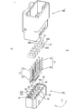
- FIG. 2 is an exploded perspective view of the connector.
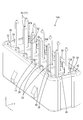
- FIG. 3 is a perspective view of the inner housing in a state where ferrite is accommodated.
- FIG. 4 is an enlarged view of the vicinity of ferrite in FIG.
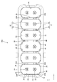
- FIG. 5 is a plan view of the inner housing in a state where ferrite is contained.
- FIG. 6 is an enlarged view of the vicinity of ferrite in FIG.
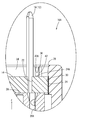
- FIG. 7 is a sectional view taken along line AA in FIG.
- FIG. 8 is an enlarged view of the vicinity of the protrusion in FIG.
- FIG. 9 is a perspective view of the inner housing in a state where ferrite is not accommodated.
- FIG. 10 is a plan view of the inner housing in a state where ferrite is not housed.
- FIG. 11 is a perspective view of the connector according to the second embodiment.
- FIG. 12 is an exploded perspective view of the connector.
- FIG. 13 is a perspective view of the inner housing in a state where two ferrites are accommodated.
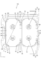
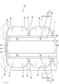
- FIG. 14 is a plan view of the inner housing in a state where two ferrites are accommodated.
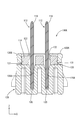
- FIG. 15 is a sectional view taken along line BB in FIG.
- a connector described in JP 2012-069270 A As an example of a conventional connector, for example, a connector described in JP 2012-069270 A is known.
- This connector includes a housing provided with a plurality of connector fitting portions for fitting with a plurality of mating connectors, a plurality of terminals attached to the housing so as to project into each connector fitting portion, and a connector.
- a noise removing unit formed of a plurality of ferrites provided for each fitting portion.
- the housing is provided with a plurality of frames, and the plurality of ferrites are located in the respective frames of the housing, and are held by the housing by a pair of biasing arms provided on the housing.
- a slide mold structure is generally required. Further, when the ferrite is held by the biasing arm, the biasing arm elastically contacts the ferrite, which may change the characteristics of the ferrite.
- the connector of the present disclosure is (1) A connector comprising: a plurality of ferrites having rounded corners at four corners of an outer peripheral side surface; and a housing having a housing portion capable of individually housing the plurality of ferrites in a first direction, the connector comprising:
- the accommodating portion includes a bottom wall portion on which the ferrite is placed, four opposing wall portions that oppose the four corner portions of the ferrite, and a protrusion that holds the ferrite in the accommodating portion,
- the protrusion is provided on at least one of the four opposing walls, and the corner of the ferrite is attached to the protrusion when housed in the housing. In a state in which the ferrite is biased and accommodated in the accommodating portion, the ferrite is not biased to the protrusion and is positioned so as to be able to contact the protrusion in the first direction.
- the corner portion of the ferrite is positioned so as to be able to contact the protrusion in the first direction.
- the biasing arm elastically contacts the ferrite to hold the ferrite in the housing, but in the above configuration, the ferrite is held in the housing without using the biasing arm. can do.
- the corners of the ferrite are not biased by the protrusions, so that it is possible to prevent the characteristics of the ferrite from changing.
- the protrusions are preferably provided on all of the four facing wall portions.
- the accommodating portion has an opening in the first direction and forms a long box shape in a second direction intersecting the first direction, and the plurality of ferrites are provided on the bottom wall portion of the accommodating portion.
- the accommodation portions are arranged side by side in the second direction, and the accommodation portion further includes a first inner wall and a second inner wall facing each other in a third direction intersecting the first direction and the second direction. It is preferable that the facing wall portion on the inner wall side and the facing wall portion on the second inner wall side facing the facing wall portion are not connected.
- the opposing wall portions are connected to each other, and the pair of adjacent ferrites are separated from each other by the opposing wall portion.
- the size can be reduced in the second direction.
- FIGS. 1 to 10 show the X direction shown in FIGS. 1 to 10 in the front in the front-rear direction (the third direction)
- the Y direction is the right in the left-right direction (the second direction)
- the Z direction is the up-down direction (the first direction). Upward.
- the connector 10 of the first embodiment is a joint connector for multiplex communication used in a vehicle, and as shown in FIG. 2, two joint terminals 12 and a plurality of (six) ferrites 14 for noise reduction. , And a housing 16.
- the joint terminal 12 is made of a conductive metal, and as shown in FIG. 2, a plurality of (six) terminal body portions 18 having a rod shape protruding upward and a shape elongated in the left-right direction are formed. It is composed of a connecting portion 20 that connects the lower ends of the terminal main body portions 18 to each other.
- the ferrite 14 has a rectangular shape, and has two insertion holes 22 penetrating the upper and lower surfaces thereof and rounded corners of the outer peripheral side surface 24. And a corner portion 24A.
- the housing 16 has a box shape that is long in the left-right direction, and has an inner housing (accommodation portion) 16A having an opening 26 that opens upward, and an outer housing 16B that accommodates the inner housing 16A. Composed of and. As shown in FIG. 5, a plurality of ferrites 14 are individually housed inside the inner housing 16A.
- the inner housing 16A has a shape that is long in the left-right direction, and includes a bottom wall portion 28 on which a plurality of ferrites 14 are placed side by side in the left-right direction, and a front end portion of the bottom wall portion 28.
- the first inner wall 30 protruding upward
- the second inner wall 32 protruding upward from the rear end of the bottom wall portion 28 and facing the first inner wall 30 in the front-rear direction, and the left inner end of the bottom wall portion 28 rising upward.
- a pair of third inner walls 34 that protrude and face each other in the left-right direction.
- the bottom wall portion 28 is provided with a pair of front and rear groove portions 28A that are long in the left-right direction, and the inner wall of the pair of groove portions 28A has a connecting portion 20 of the two joint terminals 12. Are press-fitted and held.
- the first inner wall 30 is provided with a first partition portion 38 that projects toward the space between the pair of ferrites 14 adjacent in the left-right direction and partitions the pair of adjacent ferrites 14 rearward. It is provided so as to project.
- the second inner wall 32 is provided with a second partition portion 40 that projects toward the space between the pair of adjacent ferrites 14 in the left-right direction and partitions the space between the pair of adjacent ferrites 14 to project forward.
- Each of the first partition section 38 and the second partition section 40 is provided in plurality in the left-right direction at a predetermined interval.
- the first partition portions 38 and the second partition portions 40 are arranged so as to face each other in the front-rear direction.
- the facing wall portion 36 is at a position facing the corners 24A of the ferrite 14 of each of the first partition 38 and the second partition 40 (the positions of the four corners in the inner housing 16A, and the corners of the ferrite 14). 24A, respectively).
- the opposing wall portions 36) provided in the partition portion 40 are not connected to each other, and the accommodation spaces of the adjacent ferrites 14 communicate with each other in the left-right direction.
- the housing 16 can be miniaturized in the left-right direction as compared with the configuration in which the pair of adjacent ferrites 14 are partitioned by the facing wall portion.
- a protrusion 42 is provided on the upper portion of each opposing wall 36, and the protrusion 42 faces the opening edge of the opening 26 of the inner housing 16A.
- An inclined taper portion 42A is provided (see FIG. 4).
- the ferrite 14 is housed inside the inner housing 16A through the opening 26.
- the four corners 24A of the four corners of the ferrite 14 are biased by the four protrusions 42 provided on the facing wall 36 facing the respective corners 24A, and the inner housing is pressed in slightly. It is housed inside 16A.
- the protruding portion 42 is provided with the taper portion 42A that is inclined toward the opening edge of the inner housing 16A, the corner portion 24A of the ferrite 14 slides with the taper portion 42A, and the ferrite 14 is Since it is drawn into the inner housing 16A, the ferrite 14 can be easily housed.
- the terminal body portions 18 of different joint terminals 12 are inserted into the two insertion holes 22 of the ferrite 14, respectively.
- the protruding portion 42 is located slightly above the upper surface of the ferrite 14, and the ferrite 14 is not biased by the protruding portion 42, so that the inner housing is not biased. It is housed inside 16A. As a result, it is possible to suppress a change in the characteristics of the ferrite 14 as compared with the conventional configuration in which the ferrite is housed inside the inner housing while being biased by the biasing arm.
- the corner portion 24A of the ferrite 14 is positioned so as to be able to contact the protrusion 42 from below.
- the corners 24A of the ferrite 14 come into contact with the protrusions 42 from below, so that the ferrite 14 is prevented from coming out upward, so that the ferrite 14 comes out inside the inner housing 16A.
- the ferrite 14 is held inside the inner housing 16A by the four protrusions 42, only one of the four opposing wall portions 36 facing the corner portion 24A of the ferrite 14 is provided on one of the opposing wall portions 36. Compared with the configuration in which the protrusion 42 is provided, the ferrite 14 can be more difficult to come out from the inside of the inner housing 16A.
- the corners 24A of the ferrite 14 come into contact with the protrusions 42 in the vertical direction (first direction). Since the ferrite 14 is positioned so that it can be pulled out from the inner housing (accommodation portion) 16A in the vertical direction (first direction), the ferrite 14 comes into contact with the protrusion 42, so that the ferrite 14 moves in the vertical direction (first direction). The ferrite 14 can be held in the inner housing (accommodation portion) 16A while being prevented from coming off in the first direction.
- the biasing arm elastically contacts the ferrite to hold the ferrite in the inner housing, but in the above configuration, the ferrite 14 is not used in the inner housing. It can be held in the (accommodation part) 16A. Further, when the ferrite 14 is accommodated in the inner housing (accommodation portion) 16A, the corner portion 24A of the ferrite 14 is not biased by the protrusion 42, so that the characteristics of the ferrite 14 change. Can be suppressed.
- the protrusions 42 may be provided on all of the four opposing wall portions 36.
- the ferrite 14 is further provided in the inner housing (accommodation portion) 16A as compared with the configuration in which the protrusions 42 are provided on only one opposing wall portion 36. It can be difficult to get out of.
- the inner housing (accommodating portion) 16A is open in the up-down direction (first direction), has a long box shape in the left-right direction (second direction) intersecting the up-down direction (first direction), and has a plurality of boxes.
- the ferrites 14 are arranged side by side in the left-right direction (second direction) on the bottom wall portion 28 of the inner housing (accommodation portion) 16A, and the inner housing (accommodation portion) 16A is arranged in the up-down direction (first direction) and the left-right direction.
- first inner wall 30 and a second inner wall 32 that are opposed to each other in the front-rear direction (third direction) that intersects with the (second direction), and the opposing wall portion 36 on the side of the first inner wall 30 and the second opposing wall portion 36.
- the configuration may be such that it is not connected to the facing wall portion 36 on the inner wall 32 side. Since the pair of facing wall portions 36 facing each other in the front-rear direction (third direction) are not connected, the facing wall portions are connected to each other, and the pair of adjacent ferrites 14 is partitioned by the facing wall portion.
- the housing 16 can be downsized in the left-right direction (second direction).
- the connector of the present disclosure is (1) A connector comprising: a plurality of ferrites; and a housing having a plurality of housings capable of individually housing the plurality of ferrites in a first direction, wherein the plurality of housings are in the first direction.
- the two intermediate walls are arranged side by side in the intersecting second direction and are adjacent to each other in the second direction, and the two intermediate walls are spaces in the third direction intersecting the first direction and the second direction. It is arranged with an empty space.
- the ferrites arranged in the adjoining accommodating parts can be accommodated in the accommodating part in a state of being separated from each other. As a result, it is possible to suppress a problem caused by the ferrites coming into contact with each other due to vibration or the like. Further, since the two intermediate walls are arranged with a space in the third direction, the connector can be downsized in the third direction and the weight of the connector can be reduced as compared with the case where the two intermediate walls are connected. ..
- Each of the plurality of accommodating portions has two holding walls extending along the second direction, each of the two holding walls has an elastically deformable elastic holding portion, and the elastic holding It is preferable that the ferrite is held in the accommodating portion by being sandwiched between the portions.
- Ferrite can be held in the housing by being sandwiched by the elastic holders. Further, when the elastic holding portion is provided on the intermediate wall, since the bending allowance of the elastic holding portion is provided along the second direction, the connector may increase in size in the second direction. Since the elastic holding portion is provided on the holding wall extending in the second direction, it is possible to prevent the connector from increasing in size in the second direction.
- a joint terminal having a plurality of connecting portions and a connecting portion that connects the plurality of connecting portions is provided, and each of the plurality of accommodating portions has a bottom wall that intersects the first direction, It is preferable that an accommodation groove that extends along the second direction and that accommodates the connecting portion is provided in the bottom wall at a position corresponding to the space of the intermediate wall.
- the joint terminal can be accommodated in the accommodation groove from the first direction.
- the joint terminal and the ferrite can be housed in the housing portion from the same direction, so that the efficiency of the connector assembling work can be improved.
- the connecting portion abuts the bottom surface of the housing groove, a rear cover for preventing the joint terminal from coming off from the rear side in the first direction is unnecessary, so that the number of parts of the connector can be reduced.
- an end edge of the connector opposite to the bottom wall in the first direction is at the same height as an end edge of the connector opposite to the bottom wall, or the opposite side. It is preferable to be arranged at a position higher than the edge of the.
- the edge of the intermediate wall opposite to the bottom wall in the first direction is brought into sliding contact with the joint terminal so that the joint terminal is accommodated in the accommodation groove. Will be guided to.
- the manufacturing process of the connector can be made efficient.
- the ferrite is guided into the accommodating portion by slidingly contacting the edge of the intermediate wall opposite to the bottom wall in the first direction. To be done. As a result, the manufacturing process of the connector can be made more efficient.
- One of the two intermediate walls is connected to one of the two holding walls, and extends along the third direction, and the other of the two intermediate walls is the two holding walls. It is preferable that it is connected to the other of the two and extends in the third direction.
- the strength of the intermediate wall can be improved compared to the case where the intermediate wall is separated from the holding wall. As a result, it is possible to further suppress the contact between the ferrites arranged in the adjacent accommodating portions.
- FIGS. 11 to 15 show the X direction shown in FIGS. 11 to 15 in the front in the front-back direction (third direction)
- the Y direction is the right side in the left-right direction (second direction)
- the Z direction is the up-down direction. Above (first direction).
- the connector 110 includes two joint terminals 112, a plurality of (four) ferrites 114 for noise reduction, and a housing 116.
- the joint terminal 112 is made of a conductive metal. As shown in FIG. 12, the joint terminal 112 includes four terminal body portions (connection portions) 118 and a connecting portion 120.
- the terminal main body 118 has a rod shape protruding upward.
- the connecting portion 120 has a shape that is long in the left-right direction and is continuous with the lower end portions of the plurality of terminal main body portions 118. As a result, the plurality of terminal main body portions 118 are connected and electrically connected to each other.
- the ferrite 114 As shown in FIG. 12, the ferrite 114 has a rectangular parallelepiped shape with rounded corners. Two insertion holes 122 are provided so as to penetrate the upper and lower surfaces of the ferrite 114. The terminal body 118 of the joint terminal 112 is inserted into the insertion hole 122 from below.
- the housing 116 includes an inner housing 116A and an outer housing 116B.
- the inner housing 116A has an opening 126 that opens upward, and has a box shape that is long in the left-right direction.
- the inner housing 116A includes a bottom wall 128, a peripheral wall 129 extending upward from the outer peripheral edge of the bottom wall 128, and a plurality of intermediate walls 138.
- the four ferrites 114 and the two joint terminals 112 are housed inside the inner housing 116A through the opening 126 (in FIGS. 13 and 14, only the two ferrites 114 are shown. ).
- each accommodating portion 139 is a rectangular shape that extends in the front-rear direction when viewed from above, and is the same as or slightly larger than the outer shape of each ferrite 114.
- Peripheral wall 129 As shown in FIG. 12, the upper end of the peripheral wall 129 serves as an opening edge 126A of the opening 126 of the inner housing 116A.
- FIG. 12 a portion of the peripheral wall 129 located on the front side and the rear side of each accommodation portion 139 is a holding wall 130 provided with elastic holding portions 131, respectively.
- the plurality of elastic holding portions 131 are respectively provided at positions corresponding to the side surfaces of the ferrite 114.
- the elastic holding portion 131 is elastically deformable in the front-back direction.
- the front and rear elastic holding portions 131 sandwich the ferrite 114 from the front-rear direction, whereby the ferrite 114 is held in the housing portion 139.
- the connector 110 can be made larger in the left-right direction as compared with, for example, a configuration in which the elastic holding portion 131 is provided on the intermediate wall 138 described later. Can be suppressed.
- the intermediate wall 138 is provided so as to be continuous with the holding wall 130.
- the intermediate wall 138A provided on the front (one) holding wall 130A extends from the front holding wall 130A to the space between the adjacent ferrites 114 when the ferrite 114 is accommodated. It extends (refer to the intermediate wall 138A at the right end in FIGS. 13 and 14).
- the intermediate wall 138B provided on the rear (other) holding wall 130B extends from the rear holding wall 130B toward the space between the adjacent ferrites 114 (the middle of the right end in the drawings in FIGS. 13 and 14). See wall 138B).
- the intermediate wall 138A and the intermediate wall 138B have a space S in the front-rear direction.
- the intermediate wall 138 is located between the adjacent accommodating portions 139.
- the ferrites 114 arranged in the adjacent accommodating portions 139 are separated from each other by the intermediate wall 138 and are accommodated in the accommodating portion 139.
- the connector 110 can be downsized in the front-rear direction as compared with the case where the two intermediate walls 138 are connected, and the connector 110 can be Can be lightened.
- the intermediate wall 138 is connected to the holding wall 130, the strength of the intermediate wall 138 can be improved as compared with the case where the intermediate wall is separated from the holding wall. This can further suppress contact between the ferrites 114 arranged in the adjacent housing portions 139.
- bottom wall 128, housing groove 128A As shown in FIGS. 12 and 13, the bottom wall 128 is provided below the peripheral wall 129. The bottom wall 128 is provided with two housing grooves 128A. The accommodation groove 128A extends in the left-right direction. The coupling portion 120 of the joint terminal 112 is press-fitted and accommodated in the accommodation groove 128A. The ferrite 114 is housed in the housing portion 139 with the joint terminal 112 housed in the housing groove 128A. When the ferrite 114 is housed in the housing portion 139, the ferrite 114 is placed on the bottom wall 128.
- the accommodation groove 128A is provided at a position corresponding to the space S of the intermediate wall 138.
- This allows the joint terminal 112 to be housed in the housing groove 128A from the upper opening 126. Therefore, since the joint terminal 112 and the ferrite 114 can be accommodated in the accommodating portion 139 from the same direction (the opening 126 side), for example, the ferrite is accommodated from above the inner housing and the joint terminal is accommodated from below the inner housing.
- the efficiency of the assembly work of the connector 110 can be improved as compared with the configuration.
- a rear cover for preventing the joint terminal from coming out from below is required.
- the connecting portion 120 abuts on the bottom surface of the housing groove 128A, the rear cover for preventing the joint terminal 112 from coming out from below is not necessary. Therefore, the number of parts of the connector 110 can be reduced.
- the height position T1 of the intermediate wall 138 (the intermediate wall 138A, the intermediate wall 138B) and the height position T2 of the opening edge 126A (that is, the height position of the end edge on the opposite side of the bottom wall 128). ) And are at the same height. Accordingly, when the joint terminal 112 is accommodated in the accommodation groove 128A from above, the joint terminal 112 is guided into the accommodation groove 128A by sliding the upper end edge of the intermediate wall 138 and the joint terminal 112. .. Therefore, the manufacturing process of the connector 110 can be made efficient.
- the ferrite 114 when the ferrite 114 is housed in the housing 139 from above, the ferrite 114 is guided into the housing 139 by sliding the upper end edge of the intermediate wall 138 and the ferrite 114. Thereby, the manufacturing process of the connector 110 can be made more efficient.
- the protrusions 42 are provided on the four opposing wall portions 36 that face the corners 24A of the four corners of the ferrite 14, respectively, but are provided only on any one of the opposing wall portions. It may be configured.
- the first partition section 38 (and the facing wall section 36 provided on the first partition section 38) facing each other in the front-rear direction, and the second partition section 40 (and the second partition section).
- the opposing wall portion 36) provided in 40 is not connected, and the accommodation spaces of the adjacent ferrites 14 are configured to communicate in the left-right direction, but the first partition portion and the second partition portion are connected, It is also possible to adopt a configuration in which the accommodating spaces of adjacent ferrites do not communicate with each other.
- the inner housing 16A is configured to accommodate six ferrites 14, but the number of ferrites may be less than or more than six. Further, in the second embodiment, four ferrites 114 are accommodated in the inner housing 116A, but the number of ferrites may be less than or more than four.
- the intermediate wall 138 is connected to the holding wall 130.
- the present invention is not limited to this.
- the intermediate wall is not connected to the holding wall and is separated. Also good.
- the height position T1 of the intermediate wall 138 and the height position T2 of the opening edge 126A of the opening 126 are the same height position, but the present invention is not limited to this.
- the height position of the intermediate wall may be lower or higher than the height position of the opening edge of the opening.
- Connector 12 Joint terminal 14: Ferrite 16: Housing 16A: Inner housing (accommodation part) 16B: Outer housing 18: Terminal body part 20: Connecting part 22: Insertion hole 24: Outer peripheral side face 24A: Corner part 26: Opening part 28: Bottom wall part 28A: Groove part 30: First inner wall 32: Second inner wall 34: No.
- Inner wall 36 Opposing wall part 38: 1st partition part 40: 2nd partition part 42: Protrusion part 42A: Tapered part 110: Connector 112: Joint terminal 114: Ferrite 116: Housing 116A: Inner housing 116B: Outer housing 118: Terminal body (connecting part) 120: connection part 122: insertion hole 126: opening part 126A: opening edge 128: bottom wall 128A: housing groove 129: peripheral wall 130: holding wall 130A: holding wall 130B: holding wall 131: elastic holding parts 138, 138A, 138B: Intermediate wall 139: Housing S: Space T1: Height position T2: Height position
Landscapes
- Details Of Connecting Devices For Male And Female Coupling (AREA)
Abstract
コネクタ110は、複数のフェライト114と、前記複数のフェライト114を第1方向から個別に収容可能な複数の収容部139を有するハウジング116と、を備えるコネクタ110であって、前記複数の収容部139は、前記第1方向と交差する第2方向に並んで配されており、前記第2方向について隣り合う収容部139の間には、2つの中間壁138が、前記第1方向及び前記第2方向と交差する第3方向についてスペースSを空けて配されている。
Description
本明細書によって開示される技術は、コネクタに関する。
従来のコネクタの一例として、下記特許文献1に記載のコネクタが知られている。このコネクタは、複数の相手方コネクタとそれぞれ嵌合するための複数のコネクタ嵌合部が設けられたハウジングと、各コネクタ嵌合部内に突出するように前記ハウジングに取り付けられた複数の端子と、コネクタ嵌合部ごとに設けられた複数のフェライトにより構成されるノイズ除去手段と、を備えている。
ハウジングには、複数の枠が設けられており、複数のフェライトは、ハウジングのそれぞれの枠内に位置しており、ハウジングに設けられた一対の付勢アームによりハウジングに保持されている。一対の付勢アームに設けられた2つの突出部によって、フェライトの四隅が保持されている。
特許文献1ではフェライトの四隅が付勢アームに保持されているので、隣り合うフェライト同士が振動等によって接触することが懸念される。
本開示のコネクタは、複数のフェライトと、前記複数のフェライトを第1方向から個別に収容可能な複数の収容部を有するハウジングと、を備えるコネクタであって、前記複数の収容部は、前記第1方向と交差する第2方向に並んで配されており、前記第2方向について隣り合う収容部の間には、2つの中間壁が、前記第1方向及び前記第2方向と交差する第3方向についてスペースを空けて配されている。
本明細書に開示されるコネクタによれば、フェライト同士が接触することを抑制できる。
<実施形態1>
[背景技術]
従来のコネクタの一例として、例えば、特開2012-069270号公報に記載のコネクタが知られている。このコネクタは、複数の相手方コネクタとそれぞれ嵌合するための複数のコネクタ嵌合部が設けられたハウジングと、各コネクタ嵌合部内に突出するように前記ハウジングに取り付けられた複数の端子と、コネクタ嵌合部ごとに設けられた複数のフェライトにより構成されるノイズ除去手段と、を備えている。
[背景技術]
従来のコネクタの一例として、例えば、特開2012-069270号公報に記載のコネクタが知られている。このコネクタは、複数の相手方コネクタとそれぞれ嵌合するための複数のコネクタ嵌合部が設けられたハウジングと、各コネクタ嵌合部内に突出するように前記ハウジングに取り付けられた複数の端子と、コネクタ嵌合部ごとに設けられた複数のフェライトにより構成されるノイズ除去手段と、を備えている。
ハウジングには、複数の枠が設けられており、複数のフェライトは、ハウジングのそれぞれの枠内に位置しており、ハウジングに設けられた一対の付勢アームによりハウジングに保持されている。
ハウジングの付勢アームを成形するには、一般的にスライド金型構造が必要となる。また、付勢アームによりフェライトを保持すると、付勢アームがフェライトに弾性的に接触することにより、フェライトの特性が変化する虞がある。
[本開示の実施形態1の説明]
本開示の実施態様を列記して説明する。本開示のコネクタは、
(1)外周側面の四隅に丸みを帯びた角部を有する複数のフェライトと、前記複数のフェライトを第1方向から個別に収容可能な収容部を有するハウジングと、を備えるコネクタであって、前記収容部は、前記フェライトが載置される底壁部と、前記フェライトの4つの前記角部と対向する4つの対向壁部と、前記フェライトを前記収容部内に保持する突起部と、を備え、前記突起部は、4つの前記対向壁部のうち、少なくとも1つの前記対向壁部に突設されており、前記フェライトの前記角部は、前記収容部内に収容される際、前記突起部に付勢され、前記フェライトが前記収容部内に収容された状態においては、前記突起部に付勢されておらず、且つ、前記突起部に前記第1方向から当接可能に位置している。
本開示の実施態様を列記して説明する。本開示のコネクタは、
(1)外周側面の四隅に丸みを帯びた角部を有する複数のフェライトと、前記複数のフェライトを第1方向から個別に収容可能な収容部を有するハウジングと、を備えるコネクタであって、前記収容部は、前記フェライトが載置される底壁部と、前記フェライトの4つの前記角部と対向する4つの対向壁部と、前記フェライトを前記収容部内に保持する突起部と、を備え、前記突起部は、4つの前記対向壁部のうち、少なくとも1つの前記対向壁部に突設されており、前記フェライトの前記角部は、前記収容部内に収容される際、前記突起部に付勢され、前記フェライトが前記収容部内に収容された状態においては、前記突起部に付勢されておらず、且つ、前記突起部に前記第1方向から当接可能に位置している。
フェライトが収容部内に収容されると、フェライトの角部は、突起部に第1方向から当接可能に位置しているため、フェライトが収容部から第1方向に抜けようとすると、フェライトの角部が突起部に当接することで、フェライトが第1方向に抜けることが抑制され、フェライトを収容部内に保持することができる。これにより、従来では、付勢アームがフェライトに弾性的に接触することで、フェライトを収容部内に保持する構成としていたが、上記構成では、付勢アームを用いることなく、フェライトを収容部内に保持することができる。また、フェライトは、収容部内に収容された状態においては、フェライトの角部は、突起部に付勢されていないことから、フェライトの特性が変化することを抑制することができる。
(2)前記突起部は、4つの前記対向壁部の全てに設けられていることが好ましい。
4つの対向壁部の全てに突起部を設けることで、1つの対向壁部のみに突起部が設けられている構成と比較して、さらにフェライトが収容部から抜け難くすることができる。
(3)前記収容部は、前記第1方向に開口しており、前記第1方向と交差する第2方向に長い箱状をなし、複数の前記フェライトは、前記収容部の前記底壁部に前記第2方向に並べて配されており、前記収容部は、前記第1方向及び前記第2方向と交差する第3方向に対向する第1内壁及び第2内壁をさらに備えており、前記第1内壁側の前記対向壁部とこれに対向する前記第2内壁側の前記対向壁部とは繋がっていないことが好ましい。
第3方向に対向する一対の対向壁部は繋がっていないことから、対向壁部同士が繋がっており、隣り合う一対のフェライト間が対向壁部によって仕切られている構成と比較して、ハウジングを第2方向に小型化できる。
[本開示の実施形態1の詳細]
本開示の実施形態1におけるコネクタ10を、以下に図面(図1から図10)を参照しつつ説明する。なお、本開示はこれらの例示に限定されるものではなく、特許請求の範囲によって示され、特許請求の範囲と均等の意味および範囲内でのすべての変更が含まれることが意図される。以降の説明では、図1から図10に示すX方向を前後方向(第3方向)の前方、Y方向を左右方向(第2方向)の右方、Z方向を上下方向(第1方向)の上方とする。
本開示の実施形態1におけるコネクタ10を、以下に図面(図1から図10)を参照しつつ説明する。なお、本開示はこれらの例示に限定されるものではなく、特許請求の範囲によって示され、特許請求の範囲と均等の意味および範囲内でのすべての変更が含まれることが意図される。以降の説明では、図1から図10に示すX方向を前後方向(第3方向)の前方、Y方向を左右方向(第2方向)の右方、Z方向を上下方向(第1方向)の上方とする。
実施形態1のコネクタ10は、車両に使用される多重通信用のジョイントコネクタであって、図2に示すように、2つのジョイント端子12と、ノイズ低減用の複数(6つ)のフェライト14と、ハウジング16と、から構成されている。
ジョイント端子12は、導電性金属により構成されており、図2に示すように、上方に突出する棒状をなす複数(6つ)の端子本体部18と、左右方向に長い形状をなし、複数の端子本体部18の下端側を互いに連結する連結部20と、から構成されている。
フェライト14は、図5、図6に示すように、方形状をなしており、上下の面に貫通して設けられた2つの挿通孔22と、外周側面24の四隅に設けられた丸みを帯びた角部24Aと、から構成されている。
ハウジング16は、図2に示すように、左右方向に長い箱状をなしており、上方に開口する開口部26を有するインナーハウジング(収容部)16Aと、インナーハウジング16Aが収容されるアウターハウジング16Bとから構成される。インナーハウジング16Aの内部には、図5に示すように、複数のフェライト14が個別に収容されている。
インナーハウジング16Aは、図3、図5に示すように、左右方向に長い形状をなし、複数のフェライト14が左右方向に並べて載置される底壁部28と、底壁部28の前端部から上方に突出する第1内壁30と、底壁部28の後端部から上方に突出し、第1内壁30と前後方向に対向する第2内壁32と、底壁部28の左右両端部から上方に突出し、左右方向に互いに対向する一対の第3内壁34と、を備えている。
底壁部28には、図9、図10に示すように、左右方向に長い溝部28Aが、前後一対設けられており、一対の溝部28Aの内壁には、2つのジョイント端子12の連結部20がそれぞれ圧入されて保持されている。
図3、図5に示すように、第1内壁30には、左右方向に隣り合う一対のフェライト14の間に向けて突出し、隣り合う一対のフェライト14間を仕切る第1仕切り部38が後方に突出して設けられている。一方、第2内壁32には、左右方向に隣り合う一対のフェライト14間に向けて突出し、隣り合う一対のフェライト14間を仕切る第2仕切り部40が前方に突出して設けられている。第1仕切り部38と第2仕切り部40は、いずれも左右方向に所定の間隔を空けて複数設けられている。各第1仕切り部38と各第2仕切り部40は、前後方向に対向する配置とされている。
インナーハウジング16Aの内部には、図3、図5に示すように、複数のフェライト14のそれぞれの四隅の角部24Aと対向する4つの対向壁部36が設けられている。対向壁部36は、第1仕切り部38、及び、第2仕切り部40のそれぞれのフェライト14の角部24Aと対向する位置(インナーハウジング16A内の四隅の位置であって、フェライト14の角部24Aと対向する位置)にそれぞれ設けられている。
図3、図5に示すように、前後方向に対向する第1仕切り部38(及び、第1仕切り部38に設けられた対向壁部36)、及び、第2仕切り部40(及び、第2仕切り部40に設けられた対向壁部36)は互いに繋がっておらず、隣り合うフェライト14の収容空間は左右方向に連通している。これにより、隣り合う一対のフェライト14間が対向壁部によって仕切られている構成と比較して、ハウジング16を左右方向に小型化できる。
図3、図5に示すように、それぞれの対向壁部36の上部には、突起部42が突設されており、突起部42には、インナーハウジング16Aの開口部26の開口縁に向けて傾斜するテーパー部42Aが設けられている(図4参照)。
フェライト14は、開口部26からインナーハウジング16Aの内部に収容される。フェライト14を収容する際は、フェライト14の四隅の角部24Aが、それぞれの角部24Aに対向する対向壁部36に設けられた4つの突起部42に付勢されつつ、圧入気味にインナーハウジング16Aの内部に収容される。このとき、突起部42には、インナーハウジング16Aの開口縁に向けて傾斜するテーパー部42Aが設けられているため、フェライト14の角部24Aがテーパー部42Aと摺動しつつ、フェライト14は、インナーハウジング16Aの内部に誘い込まれるため、フェライト14の収容がし易くなっている。
フェライト14がインナーハウジング16Aの内部に収容されると、フェライト14の2つの挿通孔22には、異なるジョイント端子12の端子本体部18がそれぞれ挿通される。このとき、図7、図8に示すように、突起部42は、フェライト14の上面よりも僅かに上方に位置しており、フェライト14は、突起部42に付勢されていない状態でインナーハウジング16Aの内部に収容される。これにより、従来のように、付勢アームに付勢された状態でフェライトがインナーハウジングの内部に収容される構成と比較して、フェライト14の特性が変化することを抑制することができる。
図7、図8に示すように、フェライト14がインナーハウジング16Aの内部に収容された状態では、フェライト14の角部24Aは、突起部42に下方から当接可能に位置しており、フェライト14がインナーハウジング16Aの内部から抜けようとすると、フェライト14の角部24Aが突起部42に下方から当接することで、フェライト14が上方に抜けることが抑制され、フェライト14をインナーハウジング16Aの内部に保持することができる。また、フェライト14は4つの突起部42によりインナーハウジング16Aの内部に保持されていることから、フェライト14の角部24Aと対向する4つの対向壁部36のうち、1つの対向壁部36にのみ突起部42が設けられている構成と比較して、フェライト14がインナーハウジング16Aの内部から抜け難くすることができる。
以上のように実施形態1によれば、フェライト14がインナーハウジング(収容部)16A内に収容されると、フェライト14の角部24Aは、突起部42に上下方向(第1方向)から当接可能に位置しているため、フェライト14がインナーハウジング(収容部)16Aから上下方向(第1方向)に抜けようとすると、フェライト14が突起部42に当接することで、フェライト14が上下方向(第1方向)に抜けることが抑制され、フェライト14をインナーハウジング(収容部)16A内に保持することができる。これにより、従来では、付勢アームがフェライトに弾性的に接触することで、フェライトをインナーハウジング内に保持する構成としていたが、上記構成では、付勢アームを用いることなく、フェライト14をインナーハウジング(収容部)16A内に保持することができる。また、フェライト14は、インナーハウジング(収容部)16A内に収容された状態においては、フェライト14の角部24Aは、突起部42に付勢されていないことから、フェライト14の特性が変化することを抑制することができる。
また、突起部42は、4つの対向壁部36の全てに設けられている構成としても良い。4つの対向壁部36の全てに突起部42を設けることで、1つの対向壁部36のみに突起部42が設けられている構成と比較して、さらにフェライト14がインナーハウジング(収容部)16Aから抜け難くすることができる。
また、インナーハウジング(収容部)16Aは、上下方向(第1方向)に開口しており、上下方向(第1方向)と交差する左右方向(第2方向)に長い箱状をなし、複数のフェライト14は、インナーハウジング(収容部)16Aの底壁部28に左右方向(第2方向)に並べて配されており、インナーハウジング(収容部)16Aは、上下方向(第1方向)及び左右方向(第2方向)と交差する前後方向(第3方向)に対向する第1内壁30及び第2内壁32をさらに備えており、第1内壁30側の対向壁部36とこれに対向する第2内壁32側の対向壁部36とは繋がっていない構成としても良い。前後方向(第3方向)に対向する一対の対向壁部36は繋がっていないことから、対向壁部同士が繋がっており、隣り合う一対のフェライト14間が対向壁部によって仕切られている構成と比較して、ハウジング16を左右方向(第2方向)に小型化できる。
<実施形態2>
[本開示の実施形態2の説明]
本開示の実施形態2における実施態様を列記して説明する。本開示のコネクタは、
(1)複数のフェライトと、前記複数のフェライトを第1方向から個別に収容可能な複数の収容部を有するハウジングと、を備えるコネクタであって、前記複数の収容部は、前記第1方向と交差する第2方向に並んで配されており、前記第2方向について隣り合う収容部の間には、2つの中間壁が、前記第1方向及び前記第2方向と交差する第3方向についてスペースを空けて配されている。
[本開示の実施形態2の説明]
本開示の実施形態2における実施態様を列記して説明する。本開示のコネクタは、
(1)複数のフェライトと、前記複数のフェライトを第1方向から個別に収容可能な複数の収容部を有するハウジングと、を備えるコネクタであって、前記複数の収容部は、前記第1方向と交差する第2方向に並んで配されており、前記第2方向について隣り合う収容部の間には、2つの中間壁が、前記第1方向及び前記第2方向と交差する第3方向についてスペースを空けて配されている。
中間壁によって、隣り合う収容部に配されたフェライト同士が互いに隔てられた状態で収容部内に収容することができる。これにより、振動等によってフェライト同士が接触することによる不具合を抑制できる。さらに、2つの中間壁が第3方向についてスペースを空けて配されているので、2つの中間壁が繋がっている場合と比較して第3方向についてコネクタを小型化できるとともに、コネクタを軽量化できる。
(2)前記複数の収容部のそれぞれは、前記第2方向に沿って延びる2つの保持壁を有し、前記2つの保持壁のそれぞれは弾性変形可能な弾性保持部を有し、前記弾性保持部に挟まれることにより前記フェライトが前記収容部内に保持されるようになっていることが好ましい。
弾性保持部によって挟まれることにより、フェライトを収容部内に保持することができる。また、弾性保持部が中間壁に設けられた場合、弾性保持部の撓み代を第2方向に沿って設けることになるので、コネクタが第2方向に大型化するおそれがあるが、本開示においては弾性保持部が第2方向に沿って延びる保持壁に設けられているので、コネクタが第2方向に大型化することを抑制できる。
(3)複数の接続部と、前記複数の接続部を連結する連結部と、を有するジョイント端子を備え、前記複数の収容部のそれぞれは、前記第1方向と交差する底壁を有し、前記底壁には、前記第2方向に沿って延びるとともに前記連結部が収容される収容溝が、前記中間壁の前記スペースに対応する位置に設けられていることが好ましい。
中間壁のスペースに対応する位置に収容溝が設けられているので、ジョイント端子を第1方向から収容溝内に収容することができる。これにより、ジョイント端子とフェライトとを同じ方向から収容部内に収容できるので、コネクタの組立作業の効率化を図れる。また、連結部が収容溝の底面に当たることから、ジョイント端子を第1方向について後方から抜け止めするリアカバーが不要となるので、コネクタの部品点数を削減できる。
(4)前記2つの中間壁のうち、前記第1方向について前記底壁と反対側の端縁は、前記コネクタのうち前記底壁と反対側の端縁と同じ高さ位置、または前記反対側の端縁よりも高い位置に配されていることが好ましい。
ジョイント端子を第1方向から収容溝内に収容させる際に、中間壁のうち第1方向について底壁と反対側の端縁と、ジョイント端子とを摺接させることにより、ジョイント端子が収容溝内に案内される。これにより、コネクタの製造工程を効率化できる。さらに、フェライトを第1方向から収容部内に収容させる際にも、中間壁のうち第1方向について底壁と反対側の端縁と、フェライトとを摺接させることにより、フェライトが収容部内に案内される。これにより、コネクタの製造工程をさらに効率化できる。
(5)前記2つの中間壁の一方は、前記2つの保持壁の一方と連なっており、かつ、前記第3方向に沿って延びるとともに、前記2つの中間壁の他方は、前記2つの保持壁の他方と連なっており、かつ、前記第3方向に沿って延びていることが好ましい。
中間壁が保持壁と離れている場合に比べて、中間壁の強度を向上させることができる。これにより、隣り合う収容部に配されたフェライト同士が接触することを、さらに抑制できる。
[本開示の実施形態2の詳細]
本開示の実施形態2におけるコネクタ110を、以下に図面(図11から図15)を参照しつつ説明する。以降の説明では、実施形態1と同様、図11から図15に示すX方向を前後方向(第3方向)の前方、Y方向を左右方向(第2方向)の右方、Z方向を上下方向(第1方向)の上方とする。
本開示の実施形態2におけるコネクタ110を、以下に図面(図11から図15)を参照しつつ説明する。以降の説明では、実施形態1と同様、図11から図15に示すX方向を前後方向(第3方向)の前方、Y方向を左右方向(第2方向)の右方、Z方向を上下方向(第1方向)の上方とする。
[コネクタ110]
図12に示すように、コネクタ110は、2つのジョイント端子112と、ノイズ低減用の複数(4つ)のフェライト114と、ハウジング116と、を備えて構成されている。
図12に示すように、コネクタ110は、2つのジョイント端子112と、ノイズ低減用の複数(4つ)のフェライト114と、ハウジング116と、を備えて構成されている。
[ジョイント端子112]
ジョイント端子112は、導電性金属により構成されている。図12に示すように、ジョイント端子112は、4つの端子本体部(接続部)118と、連結部120と、を備えて構成されている。端子本体部118は、上方に突出する棒状をなしている。連結部120は、左右方向に長い形状をなし、複数の端子本体部118の下端部と連なっている。これにより、複数の端子本体部118は連結され、互いに電気的に接続されている。
ジョイント端子112は、導電性金属により構成されている。図12に示すように、ジョイント端子112は、4つの端子本体部(接続部)118と、連結部120と、を備えて構成されている。端子本体部118は、上方に突出する棒状をなしている。連結部120は、左右方向に長い形状をなし、複数の端子本体部118の下端部と連なっている。これにより、複数の端子本体部118は連結され、互いに電気的に接続されている。
[フェライト114]
図12に示すように、フェライト114は、角が丸められた直方体状をなしている。フェライト114の上下の面には、2つの挿通孔122が貫通して設けられている。挿通孔122には、ジョイント端子112の端子本体部118が下方から挿通される。
図12に示すように、フェライト114は、角が丸められた直方体状をなしている。フェライト114の上下の面には、2つの挿通孔122が貫通して設けられている。挿通孔122には、ジョイント端子112の端子本体部118が下方から挿通される。
[ハウジング116]
図12に示すように、ハウジング116は、インナーハウジング116Aと、アウターハウジング116Bと、を備えて構成されている。
図12に示すように、ハウジング116は、インナーハウジング116Aと、アウターハウジング116Bと、を備えて構成されている。
[インナーハウジング116A]
図12に示すように、インナーハウジング116Aは、上方に開口する開口部126を有しており、左右方向に長い箱状をなしている。インナーハウジング116Aは、底壁128と、底壁128の外周縁から上方に延びる周壁129と、複数の中間壁138と、を備えて構成されている。図12から図14に示すように、4つのフェライト114および2つのジョイント端子112は、開口部126からインナーハウジング116Aの内部に収容される(図13、図14においては、2つのフェライト114のみ図示)。
図12に示すように、インナーハウジング116Aは、上方に開口する開口部126を有しており、左右方向に長い箱状をなしている。インナーハウジング116Aは、底壁128と、底壁128の外周縁から上方に延びる周壁129と、複数の中間壁138と、を備えて構成されている。図12から図14に示すように、4つのフェライト114および2つのジョイント端子112は、開口部126からインナーハウジング116Aの内部に収容される(図13、図14においては、2つのフェライト114のみ図示)。
[収容部139]
図12に示すように、周壁129、底壁128、および、中間壁138によって、インナーハウジング116A内には、4つの収容部139が形成されている。4つの収容部139は、左右方向に並んで配されている。4つの収容部139には、4つのフェライト114が個別に収容される。各収容部139の内形状は、上方から見て前後方向に延びる長方形状をなしており、各フェライト114の外形状と同じか、やや大きく形成されている。
図12に示すように、周壁129、底壁128、および、中間壁138によって、インナーハウジング116A内には、4つの収容部139が形成されている。4つの収容部139は、左右方向に並んで配されている。4つの収容部139には、4つのフェライト114が個別に収容される。各収容部139の内形状は、上方から見て前後方向に延びる長方形状をなしており、各フェライト114の外形状と同じか、やや大きく形成されている。
[周壁129]
図12に示すように、周壁129の上端部は、インナーハウジング116Aの開口部126の開口縁126Aとなっている。
図12に示すように、周壁129の上端部は、インナーハウジング116Aの開口部126の開口縁126Aとなっている。
[保持壁130、弾性保持部131]
図12に示すように、周壁129のうち、各収容部139の前側および後側に位置する部分は、それぞれ弾性保持部131が設けられた保持壁130とされる。
図12に示すように、周壁129のうち、各収容部139の前側および後側に位置する部分は、それぞれ弾性保持部131が設けられた保持壁130とされる。
図12から図14に示すように、複数の弾性保持部131は、フェライト114の側面と対応する位置にそれぞれ設けられている。弾性保持部131は、前後方向について弾性変形可能となっている。図15に示すように、前後の弾性保持部131がフェライト114を前後方向から挟むことによって、フェライト114は収容部139内に保持されている。左右方向に沿って延びる保持壁130に弾性保持部131を設けることによって、例えば、弾性保持部131が後述する中間壁138に設けられる構成と比較して、コネクタ110が左右方向に大型化することを抑制できる。
[中間壁138]
図12から図14に示すように、中間壁138は、保持壁130にそれぞれ連なって設けられている。保持壁130のうち、前方(一方)の保持壁130Aに設けられている中間壁138Aは、フェライト114が収容されている状態において、前方の保持壁130Aから、隣り合うフェライト114の間に向けて延びている(図13、図14における図示右端の中間壁138Aを参照)。また、後方(他方)の保持壁130Bに設けられている中間壁138Bは、後方の保持壁130Bから、隣り合うフェライト114の間に向けて延びている(図13、図14における図示右端の中間壁138Bを参照)。図13、図14に示すように、中間壁138Aと中間壁138Bとは、前後方向についてスペースSが空けられている。
図12から図14に示すように、中間壁138は、保持壁130にそれぞれ連なって設けられている。保持壁130のうち、前方(一方)の保持壁130Aに設けられている中間壁138Aは、フェライト114が収容されている状態において、前方の保持壁130Aから、隣り合うフェライト114の間に向けて延びている(図13、図14における図示右端の中間壁138Aを参照)。また、後方(他方)の保持壁130Bに設けられている中間壁138Bは、後方の保持壁130Bから、隣り合うフェライト114の間に向けて延びている(図13、図14における図示右端の中間壁138Bを参照)。図13、図14に示すように、中間壁138Aと中間壁138Bとは、前後方向についてスペースSが空けられている。
図12から図14に示すように、中間壁138は、隣り合う収容部139の間に位置している。隣り合う収容部139に配されたフェライト114同士は、中間壁138によって互いに隔てられ、収容部139内に収容されている。これにより、振動等によってフェライト114同士が接触することによる不具合を抑制できる。さらに、2つの中間壁138が前後方向についてスペースSを空けて配されているので、2つの中間壁138が繋がっている場合と比較して前後方向についてコネクタ110を小型化できるとともに、コネクタ110を軽量化できる。また、中間壁138が保持壁130に連なっていることで、中間壁が保持壁と離れている場合に比べて、中間壁138の強度を向上させることができる。これにより、隣り合う収容部139に配されたフェライト114同士が接触することを、さらに抑制できる。
[底壁128、収容溝128A]
図12、図13に示すように、底壁128は、周壁129の下部に設けられている。底壁128には、2つの収容溝128Aが設けられている。収容溝128Aは、左右方向に沿って延びている。収容溝128Aには、ジョイント端子112の連結部120が圧入により収容されている。フェライト114は、ジョイント端子112が収容溝128Aに収容された状態で、収容部139に収容される。フェライト114が収容部139に収容されると、フェライト114は底壁128に載置される。
図12、図13に示すように、底壁128は、周壁129の下部に設けられている。底壁128には、2つの収容溝128Aが設けられている。収容溝128Aは、左右方向に沿って延びている。収容溝128Aには、ジョイント端子112の連結部120が圧入により収容されている。フェライト114は、ジョイント端子112が収容溝128Aに収容された状態で、収容部139に収容される。フェライト114が収容部139に収容されると、フェライト114は底壁128に載置される。
図13、図14に示すように、収容溝128Aは、中間壁138のスペースSに対応する位置に設けられている。これにより、ジョイント端子112を上方の開口部126から収容溝128A内に収容することができる。したがって、ジョイント端子112とフェライト114とを同じ方向(開口部126側)から収容部139内に収容できるので、たとえば、フェライトをインナーハウジングの上方から収容し、ジョイント端子をインナーハウジングの下方から収容する構成と比較して、コネクタ110の組立作業の効率化を図れる。また、ジョイント端子をインナーハウジングの下方から収容する構成の場合、一般的に、ジョイント端子を下方から抜け止めするためのリアカバーが必要となる。しかし、実施形態2においては、連結部120が収容溝128Aの底面に当たることから、ジョイント端子112を下方から抜け止めするリアカバーが不要となる。したがって、コネクタ110の部品点数を削減できる。
図13に示すように、中間壁138(中間壁138A、中間壁138B)の高さ位置T1と、開口縁126Aの高さ位置T2(すなわち、底壁128の反対側の端縁の高さ位置)とは、同じ高さ位置となっている。これにより、ジョイント端子112を上方から収容溝128A内に収容させる際に、中間壁138の上端縁と、ジョイント端子112とを摺接させることにより、ジョイント端子112が収容溝128A内に案内される。したがって、コネクタ110の製造工程を効率化できる。さらに、フェライト114を上から収容部139内に収容させる際にも、中間壁138の上端縁と、フェライト114とを摺接させることにより、フェライト114が収容部139内に案内される。これにより、コネクタ110の製造工程をさらに効率化できる。
<他の実施形態>
本明細書によって開示される技術は上記記述及び図面によって説明した実施形態に限定されるものではなく、例えば次のような種々の態様も含まれる。
本明細書によって開示される技術は上記記述及び図面によって説明した実施形態に限定されるものではなく、例えば次のような種々の態様も含まれる。
(1)実施形態1では、突起部42は、フェライト14の四隅の角部24Aと対向する4つの対向壁部36にそれぞれ設けられる構成としたが、いずれか1つの対向壁部にのみ設けられる構成としても良い。
(2)実施形態1では、前後方向に対向する第1仕切り部38(及び、第1仕切り部38に設けられた対向壁部36)、及び、第2仕切り部40(及び、第2仕切り部40に設けられた対向壁部36)は繋がっておらず、隣り合うフェライト14の収容空間は左右方向に連通している構成としたが、第1仕切り部及び第2仕切り部が繋がっており、隣り合うフェライトの収容空間が連通していない構成としても良い。
(3)実施形態1では、インナーハウジング16Aには、6つのフェライト14が収容される構成としたが、フェライトの数は、6つより少なくても多くても良い。また、実施形態2では、インナーハウジング116Aには、4つのフェライト114が収容される構成としたが、フェライトの数は、4つより少なくても多くても良い。
(4)実施形態2では、中間壁138は、保持壁130と連なっている構成としたが、これに限られることはなく、例えば、中間壁は保持壁と連なっておらず、離れている構成としても良い。
(5)実施形態2では、中間壁138の高さ位置T1と、開口部126の開口縁126Aの高さ位置T2は、同じ高さ位置である構成としたが、これに限られることはなく、例えば、中間壁の高さ位置は、開口部の開口縁の高さ位置よりも低い位置でも良いし、高い位置でも良い。
10: コネクタ
12: ジョイント端子
14: フェライト
16: ハウジング
16A: インナーハウジング(収容部)
16B: アウターハウジング
18: 端子本体部
20: 連結部
22: 挿通孔
24: 外周側面
24A: 角部
26: 開口部
28: 底壁部
28A: 溝部
30: 第1内壁
32: 第2内壁
34: 第3内壁
36: 対向壁部
38: 第1仕切り部
40: 第2仕切り部
42: 突起部
42A: テーパー部
110: コネクタ
112: ジョイント端子
114: フェライト
116: ハウジング
116A: インナーハウジング
116B: アウターハウジング
118: 端子本体部(接続部)
120: 連結部
122: 挿通孔
126: 開口部
126A: 開口縁
128: 底壁
128A: 収容溝
129: 周壁
130: 保持壁
130A: 保持壁
130B: 保持壁
131: 弾性保持部
138、138A、138B: 中間壁
139: 収容部
S: スペース
T1: 高さ位置
T2: 高さ位置
12: ジョイント端子
14: フェライト
16: ハウジング
16A: インナーハウジング(収容部)
16B: アウターハウジング
18: 端子本体部
20: 連結部
22: 挿通孔
24: 外周側面
24A: 角部
26: 開口部
28: 底壁部
28A: 溝部
30: 第1内壁
32: 第2内壁
34: 第3内壁
36: 対向壁部
38: 第1仕切り部
40: 第2仕切り部
42: 突起部
42A: テーパー部
110: コネクタ
112: ジョイント端子
114: フェライト
116: ハウジング
116A: インナーハウジング
116B: アウターハウジング
118: 端子本体部(接続部)
120: 連結部
122: 挿通孔
126: 開口部
126A: 開口縁
128: 底壁
128A: 収容溝
129: 周壁
130: 保持壁
130A: 保持壁
130B: 保持壁
131: 弾性保持部
138、138A、138B: 中間壁
139: 収容部
S: スペース
T1: 高さ位置
T2: 高さ位置
Claims (8)
- 複数のフェライトと、前記複数のフェライトを第1方向から個別に収容可能な複数の収容部を有するハウジングと、を備えるコネクタであって、
前記複数の収容部は、前記第1方向と交差する第2方向に並んで配されており、
前記第2方向について隣り合う収容部の間には、2つの中間壁が、前記第1方向及び前記第2方向と交差する第3方向についてスペースを空けて配されているコネクタ。 - 前記複数の収容部のそれぞれは、前記第2方向に沿って延びる2つの保持壁を有し、
前記2つの保持壁のそれぞれは弾性変形可能な弾性保持部を有し、前記弾性保持部に挟まれることにより前記フェライトが前記収容部内に保持されるようになっている、請求項1に記載のコネクタ。 - 複数の接続部と、前記複数の接続部を連結する連結部と、を有するジョイント端子を備え、
前記複数の収容部のそれぞれは、前記第1方向と交差する底壁を有し、
前記底壁には、前記第2方向に沿って延びるとともに前記連結部が収容される収容溝が、前記中間壁の前記スペースに対応する位置に設けられている請求項2に記載のコネクタ。 - 前記2つの中間壁のうち、前記第1方向について前記底壁と反対側の端縁は、前記コネクタのうち前記底壁と反対側の端縁と同じ高さ位置、または前記反対側の端縁よりも高い位置に配されている、請求項3に記載のコネクタ。
- 前記2つの中間壁の一方は、前記2つの保持壁の一方と連なっており、かつ、前記第3方向に沿って延びるとともに、前記2つの中間壁の他方は、前記2つの保持壁の他方と連なっており、かつ、前記第3方向に沿って延びている請求項2から請求項4のいずれか1項に記載のコネクタ。
- 前記複数のフェライトのそれぞれは外周側面の四隅に丸みを帯びた角部を有し、
前記収容部は、
前記フェライトが載置される底壁部と、
前記フェライトの4つの前記角部と対向する4つの対向壁部と、
前記フェライトを前記収容部内に保持する突起部と、を備え、
前記突起部は、4つの前記対向壁部のうち、少なくとも1つの前記対向壁部に突設されており、
前記フェライトの前記角部は、前記フェライトが前記収容部内に収容される際、前記突起部に付勢され、前記フェライトが前記収容部内に収容された状態においては、前記突起部に付勢されておらず、且つ、前記突起部に前記第1方向から当接可能に位置している請求項1に記載のコネクタ。 - 前記突起部は、4つの前記対向壁部の全てに設けられている請求項6に記載のコネクタ。
- 前記収容部は、前記第1方向に開口しており、前記第1方向と交差する第2方向に長い箱状をなし、
複数の前記フェライトは、前記収容部の前記底壁部に前記第2方向に並べて配されており、
前記収容部は、前記第1方向及び前記第2方向と交差する第3方向に対向する第1内壁及び第2内壁をさらに備えており、
前記第1内壁側の前記対向壁部とこれに対向する前記第2内壁側の前記対向壁部とは繋がっていない請求項6又は請求項7に記載のコネクタ。
Priority Applications (2)
| Application Number | Priority Date | Filing Date | Title |
|---|---|---|---|
| US16/980,193 US11276968B2 (en) | 2018-12-05 | 2019-11-19 | Connector |
| CN201980015637.9A CN111788744B (zh) | 2018-12-05 | 2019-11-19 | 连接器 |
Applications Claiming Priority (4)
| Application Number | Priority Date | Filing Date | Title |
|---|---|---|---|
| JP2018228050 | 2018-12-05 | ||
| JP2018-228050 | 2018-12-05 | ||
| JP2019111909A JP6731170B2 (ja) | 2018-12-05 | 2019-06-17 | コネクタ |
| JP2019-111909 | 2019-06-17 |
Publications (1)
| Publication Number | Publication Date |
|---|---|
| WO2020116145A1 true WO2020116145A1 (ja) | 2020-06-11 |
Family
ID=70974640
Family Applications (1)
| Application Number | Title | Priority Date | Filing Date |
|---|---|---|---|
| PCT/JP2019/045170 Ceased WO2020116145A1 (ja) | 2018-12-05 | 2019-11-19 | コネクタ |
Country Status (3)
| Country | Link |
|---|---|
| US (1) | US11276968B2 (ja) |
| CN (1) | CN111788744B (ja) |
| WO (1) | WO2020116145A1 (ja) |
Citations (4)
| Publication number | Priority date | Publication date | Assignee | Title |
|---|---|---|---|---|
| JPS50156789U (ja) * | 1974-06-12 | 1975-12-25 | ||
| JPH07230853A (ja) * | 1994-01-12 | 1995-08-29 | Molex Inc | フィルタ付きの電気コネクタ組立体 |
| JP2012009325A (ja) * | 2010-06-25 | 2012-01-12 | Yazaki Corp | 多重通信用ジョイントコネクタ |
| JP2012069270A (ja) * | 2010-09-21 | 2012-04-05 | Yazaki Corp | コネクタ |
Family Cites Families (4)
| Publication number | Priority date | Publication date | Assignee | Title |
|---|---|---|---|---|
| JPH05234643A (ja) * | 1992-02-21 | 1993-09-10 | Tdk Corp | ノイズ対策型コネクタおよび同コネクタ用ノイズ除去部品 |
| US5286221A (en) | 1992-10-19 | 1994-02-15 | Molex Incorporated | Filtered electrical connector assembly |
| US8690607B2 (en) * | 2012-08-08 | 2014-04-08 | Yazaki Corporation | Joint connector |
| JP2014229488A (ja) * | 2013-05-22 | 2014-12-08 | 株式会社オートネットワーク技術研究所 | フェライトコア内蔵コネクタ |
-
2019
- 2019-11-19 US US16/980,193 patent/US11276968B2/en active Active
- 2019-11-19 CN CN201980015637.9A patent/CN111788744B/zh not_active Expired - Fee Related
- 2019-11-19 WO PCT/JP2019/045170 patent/WO2020116145A1/ja not_active Ceased
Patent Citations (4)
| Publication number | Priority date | Publication date | Assignee | Title |
|---|---|---|---|---|
| JPS50156789U (ja) * | 1974-06-12 | 1975-12-25 | ||
| JPH07230853A (ja) * | 1994-01-12 | 1995-08-29 | Molex Inc | フィルタ付きの電気コネクタ組立体 |
| JP2012009325A (ja) * | 2010-06-25 | 2012-01-12 | Yazaki Corp | 多重通信用ジョイントコネクタ |
| JP2012069270A (ja) * | 2010-09-21 | 2012-04-05 | Yazaki Corp | コネクタ |
Also Published As
| Publication number | Publication date |
|---|---|
| CN111788744A (zh) | 2020-10-16 |
| US20210013683A1 (en) | 2021-01-14 |
| US11276968B2 (en) | 2022-03-15 |
| CN111788744B (zh) | 2022-05-24 |
Similar Documents
| Publication | Publication Date | Title |
|---|---|---|
| JP5836715B2 (ja) | シールドコネクタ | |
| US8992259B2 (en) | Connector having noise removal capability | |
| JP4665674B2 (ja) | コネクタ | |
| TWI528659B (zh) | 具有介面接地特徵結構之電氣連接器 | |
| US10910761B2 (en) | Connector having a ferrite and a sealing member | |
| KR102806515B1 (ko) | 전기 커넥터 | |
| JP2019133824A (ja) | コネクタ及びコネクタアセンブリ | |
| JP2021064437A (ja) | コネクタ | |
| JP6731170B2 (ja) | コネクタ | |
| US7234951B2 (en) | Electrical connector with protective cover for post header | |
| JP3622946B2 (ja) | コネクタ | |
| WO2020116145A1 (ja) | コネクタ | |
| JP4774956B2 (ja) | コネクタ、及びコネクタ用レセプタクル | |
| JP2007172907A (ja) | 複合型コネクタ | |
| US20200083632A1 (en) | Connector | |
| JP7315396B2 (ja) | コネクタ | |
| JP2019192613A (ja) | コネクタ | |
| JP2023035715A (ja) | コネクタ | |
| KR102366174B1 (ko) | 플러그 커넥터 및 이를 포함하는 커넥터 어셈블리 | |
| US20250316922A1 (en) | Electric connector and pair of electric connectors | |
| CN101867102B (zh) | 电连接器 | |
| CN120691163A (zh) | 连接器和连接器构成部件组 | |
| JP2001229989A (ja) | ジョイントコネクタ | |
| KR102366159B1 (ko) | 리셉터클 커넥터 및 이를 포함하는 커넥터 어셈블리 | |
| JPH051185U (ja) | フイルタコネクタ |
Legal Events
| Date | Code | Title | Description |
|---|---|---|---|
| 121 | Ep: the epo has been informed by wipo that ep was designated in this application |
Ref document number: 19893648 Country of ref document: EP Kind code of ref document: A1 |
|
| NENP | Non-entry into the national phase |
Ref country code: DE |
|
| 122 | Ep: pct application non-entry in european phase |
Ref document number: 19893648 Country of ref document: EP Kind code of ref document: A1 |