WO2020116132A1 - 撮像デバイスおよび撮像装置 - Google Patents
撮像デバイスおよび撮像装置 Download PDFInfo
- Publication number
- WO2020116132A1 WO2020116132A1 PCT/JP2019/044927 JP2019044927W WO2020116132A1 WO 2020116132 A1 WO2020116132 A1 WO 2020116132A1 JP 2019044927 W JP2019044927 W JP 2019044927W WO 2020116132 A1 WO2020116132 A1 WO 2020116132A1
- Authority
- WO
- WIPO (PCT)
- Prior art keywords
- lens
- image pickup
- imaging
- image
- conditional expression
- Prior art date
- Legal status (The legal status is an assumption and is not a legal conclusion. Google has not performed a legal analysis and makes no representation as to the accuracy of the status listed.)
- Ceased
Links
Images


Classifications
-
- G—PHYSICS
- G02—OPTICS
- G02B—OPTICAL ELEMENTS, SYSTEMS OR APPARATUS
- G02B13/00—Optical objectives specially designed for the purposes specified below
- G02B13/001—Miniaturised objectives for electronic devices, e.g. portable telephones, webcams, PDAs, small digital cameras
- G02B13/0015—Miniaturised objectives for electronic devices, e.g. portable telephones, webcams, PDAs, small digital cameras characterised by the lens design
- G02B13/002—Miniaturised objectives for electronic devices, e.g. portable telephones, webcams, PDAs, small digital cameras characterised by the lens design having at least one aspherical surface
- G02B13/0035—Miniaturised objectives for electronic devices, e.g. portable telephones, webcams, PDAs, small digital cameras characterised by the lens design having at least one aspherical surface having three lenses
-
- G—PHYSICS
- G02—OPTICS
- G02B—OPTICAL ELEMENTS, SYSTEMS OR APPARATUS
- G02B13/00—Optical objectives specially designed for the purposes specified below
- G02B13/001—Miniaturised objectives for electronic devices, e.g. portable telephones, webcams, PDAs, small digital cameras
- G02B13/0015—Miniaturised objectives for electronic devices, e.g. portable telephones, webcams, PDAs, small digital cameras characterised by the lens design
- G02B13/002—Miniaturised objectives for electronic devices, e.g. portable telephones, webcams, PDAs, small digital cameras characterised by the lens design having at least one aspherical surface
- G02B13/004—Miniaturised objectives for electronic devices, e.g. portable telephones, webcams, PDAs, small digital cameras characterised by the lens design having at least one aspherical surface having four lenses
-
- G—PHYSICS
- G02—OPTICS
- G02B—OPTICAL ELEMENTS, SYSTEMS OR APPARATUS
- G02B13/00—Optical objectives specially designed for the purposes specified below
- G02B13/001—Miniaturised objectives for electronic devices, e.g. portable telephones, webcams, PDAs, small digital cameras
- G02B13/0055—Miniaturised objectives for electronic devices, e.g. portable telephones, webcams, PDAs, small digital cameras employing a special optical element
- G02B13/006—Miniaturised objectives for electronic devices, e.g. portable telephones, webcams, PDAs, small digital cameras employing a special optical element at least one element being a compound optical element, e.g. cemented elements
-
- G—PHYSICS
- G02—OPTICS
- G02B—OPTICAL ELEMENTS, SYSTEMS OR APPARATUS
- G02B13/00—Optical objectives specially designed for the purposes specified below
- G02B13/04—Reversed telephoto objectives
-
- G—PHYSICS
- G02—OPTICS
- G02B—OPTICAL ELEMENTS, SYSTEMS OR APPARATUS
- G02B9/00—Optical objectives characterised both by the number of the components and their arrangements according to their sign, i.e. + or -
- G02B9/12—Optical objectives characterised both by the number of the components and their arrangements according to their sign, i.e. + or - having three components only
-
- H—ELECTRICITY
- H04—ELECTRIC COMMUNICATION TECHNIQUE
- H04N—PICTORIAL COMMUNICATION, e.g. TELEVISION
- H04N23/00—Cameras or camera modules comprising electronic image sensors; Control thereof
- H04N23/50—Constructional details
-
- H—ELECTRICITY
- H04—ELECTRIC COMMUNICATION TECHNIQUE
- H04N—PICTORIAL COMMUNICATION, e.g. TELEVISION
- H04N23/00—Cameras or camera modules comprising electronic image sensors; Control thereof
- H04N23/60—Control of cameras or camera modules
Definitions
- This technology relates to imaging devices. Specifically, the present invention relates to an image pickup device and an image pickup apparatus including an image pickup lens.
- This technology was created in view of such circumstances, and aims to improve the performance, wide angle and low profile of a lens based on the first group configuration.
- the present technology has been made in order to solve the above-mentioned problems, and the first side surface is arranged in order from the object side toward the image surface side without sandwiching air, and each surface is an aspherical surface.
- An imaging device comprising: an imaging lens including first to third lenses having a shape; and an imaging element arranged on the image side of the imaging lens and having a cover glass attached to the imaging surface without an air gap. is there. This brings about the effect of improving the performance of the image pickup device and reducing the wide angle and the height.
- the first lens may be a negative lens
- the second lens may be a positive lens
- the third lens may be a negative lens
- the imaging lens may satisfy the following conditional expression (a).
- f is the focal length of the lens system
- R1 is the radius of curvature of the object-side first surface.
- the image pickup lens may satisfy the following conditional expression (b).
- f is the focal length of the lens system
- R2 is the radius of curvature of the second surface.
- the image pickup lens may satisfy the following conditional expression (c).
- f is the focal length of the lens system
- R3 is the radius of curvature of the third surface.
- the image pickup lens may satisfy the following conditional expression (d).
- Ym is the maximum image height
- TT is the total optical length.
- the cover glass has a maximum principal ray incident angle of incident light exceeding 35°, refracts the incident light, and relaxes the exit angle to the imaging surface by 5° or more. May be.
- the first side surface may further include a fourth lens arranged between the image pickup lens and the image pickup element with air interposed therebetween.
- a second side surface of the present technology is an imaging lens including first to third lenses that are arranged in order from the object side toward the image surface side without sandwiching air and each surface has an aspherical shape.
- An image pickup device including an image pickup device arranged on the image plane side of the image pickup lens and having a cover glass attached to the image pickup surface without an air gap, and a signal for performing predetermined signal processing on the output of the image pickup device.
- the image pickup apparatus includes a processing unit. This brings about an effect that the performance of the image pickup apparatus is improved, and the wide angle and the height are reduced.
- the image pickup device may have optical distortion in the entire optical system, and the signal processing unit may correct the optical distortion with respect to the output of the image pickup device. ..
- R indicates the radius of curvature.
- D corresponding to the surface number i indicates the axial upper surface distance between the i-th surface and the (i+1)-th surface counted from the object side.
- Nd indicates the refractive index of a glass material or a material having a surface on the object side with respect to the d-line (wavelength 587.6 nm).
- ⁇ d indicates the Abbe number for the d-line of the glass material or material having the i-th surface on the object side.
- INFINITY indicates that the surface is a flat surface.
- STO in the surface number indicates that the surface is an aperture stop.
- f indicates the focal length.
- F indicates an F value (F number, numerical aperture).
- ⁇ indicates a half angle of view.
- H indicates the total optical length.
- some imaging lenses used in the embodiments have an aspherical lens surface.
- the distance (sag amount) in the optical axis direction from the apex of the lens surface is “x”
- the height in the direction perpendicular to the optical axis is “y”
- the paraxial curvature (1/r) at the lens apex is “c”
- the conic constant is "K”
- This monofocal lens is one that is used by being mounted in a device represented by a small image pickup device mounted in a small information terminal device such as a mobile phone (including a smartphone), a mobile PC, a wearable device, or the like.
- a mobile phone including a smartphone
- a mobile PC including a mobile PC
- a wearable device or the like.
- an image sensor such as a CCD (Charge Coupled Device) or a CMOS (Complementary Metal Oxide Semiconductor) is arranged on the image forming plane of this single focus lens.
- an optical member may be arranged in addition to a cover glass made of resin or glass, an infrared cut filter, a low pass filter, or the like.
- An image pickup device of the present disclosure includes an image pickup lens including first to third lenses arranged in order from the object side toward the image plane side without sandwiching air and each surface having an aspherical shape, and The image pickup device is provided on the image plane side, and the cover glass is attached to the image pickup plane without an air gap. In this way, the optical total length can be shortened by arranging the first to third lenses without sandwiching air.
- the first lens is a negative lens
- the second lens is a positive lens
- the third lens is a negative lens
- f focal length of lens system
- R1 radius of curvature of object-side first surface
- R2 radius of curvature of second surface
- R3 radius of curvature of third surface
- conditional expression (d) 1 ⁇ TT/Ym ⁇ 3
- Ym Maximum image height (mm)
- TT Total optical length (mm)
- the cover glass has a maximum principal ray incident angle of incident light exceeding 35° and refracts the incident light to relax the exit angle to the imaging surface by 5° or more. It That is, the high principal ray incident angle (CRA: Chief Ray Angle) emitted by the imaging lens is relaxed by utilizing the refraction of the cover glass. As a result, a compact, low-profile, bright wide-angle lens can be realized.
- CRA Chief Ray Angle
- the imaging device of the present disclosure may further include a fourth lens arranged between the imaging lens and the imaging element with air interposed therebetween.
- the basic configuration of the image pickup device of the present disclosure is such that the first lens, the second lens, and the third lens on the object side, which are arranged in order without sandwiching air from the object side toward the image surface side, are arranged without an air gap.
- the above-mentioned triplet lens is constructed.
- the first lens has a biconcave shape.
- the second lens has a biconvex shape.
- the third lens has a wavy surface shape, but has a substantially biconcave shape.
- the light rays emitted from the imaging lens have a principal ray incident angle increasing from the central portion toward the peripheral portion.
- the image side has an image pickup element in which a cover glass is attached to the image pickup surface without an air gap. The light beam emitted from the image pickup lens is refracted by the cover glass, the principal ray angle is relaxed, and enters the image pickup element to have desired optical characteristics.
- the operation of the conditional expression will be described below.
- Conditional expression (a) is a conditional expression regarding the radius of curvature of the object-side first surface of the object-side first lens, and represents that this surface is concave on the object side.
- the upper limit is correctable, so this formula is necessary.
- the conditional expression (b) is a conditional expression regarding the radius of curvature of the cemented portion between the image side of the object-side first lens and the object side of the second lens, and is necessary for efficiently correcting the off-axis chromatic aberration.
- a convex lens made of a glass material having a small dispersion and a concave lens made of a glass material having a large dispersion are cemented together to correct chromatic aberration and improve the imaging performance, but this is only an axial characteristic.
- the camera lens also combines the opposite to give off-axis characteristics. The difference in dispersion at that time is reduced.
- a glass material with a large wavelength dispersion and a small Abbe number is provided on the incident-side first surface on the object side, the effect of wavelength dispersion becomes too large and correction cannot be performed. Therefore, a glass material with a large Abbe number on the incident surface is optimal. Become. Further, for the reason described in the conditional expression (a), a glass material having a concave shape and a little more dispersion is provided on the next surface to form a convex shape to correct the off-axis aberration color.
- the lower limit is specified as a manufacturing limit because the radius of curvature becomes too small and the error greatly affects the performance.
- the upper limit is this value because the correction of chromatic aberration is insufficient and affects the overall performance.
- Conditional expression (c) is a conditional expression regarding the radius of curvature of the cemented portion between the image side of the object side second lens and the object side of the third lens, and in order to reduce axial chromatic aberration and efficiently correct the field curvature. Will be needed.
- a convex lens made of a glass material having a small dispersion and a concave lens made of a glass material having a large dispersion are cemented together to correct chromatic aberration and improve the imaging performance.
- a similar method is adopted also in the imaging device of the present disclosure.
- the concave shape of the third lens makes the optical path through the lens longer in the periphery than in the center, thereby correcting field curvature.
- the lower limit is defined as the lower limit because the curvature becomes gentle and the overall performance deteriorates.
- the upper limit is defined as a manufacturing limit because the radius of curvature becomes too small and the error greatly affects the performance.
- conditional expression (d) represents the relationship between the maximum image height and the optical total length, and the lower limit of the optical length is shortened because the aberration correction is performed by the negative action of the first lens on the object side. Due to the limitations.
- the upper limit is due to the intended use of the imaging device of the present disclosure. It is not intended to have a long optical length because it is used for a small module. As a result, the value shown in conditional expression (d) becomes the upper limit.
- the first embodiment is a numerical example of a CMOS image sensor for HD (1296 ⁇ 816 pixels) having a size of 1/10.49 and a pitch of 1.12 ⁇ m.
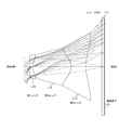
- FIG. 1 is a diagram showing a lens configuration of an image pickup device according to the first embodiment of the present technology.
- the imaging lens according to the first embodiment includes, in order from the object side, a first lens L11 having a negative refractive power, a second lens L12 having a positive refractive power, and a third lens having a negative refractive power. And L13.
- These first to third lenses (L11 to L13) are arranged without an air gap, and constitute one group of triplet lenses.
- the image pickup device also includes an image pickup element 118 arranged on the image plane side of the image pickup lens.
- a cover glass 117 is attached to the image pickup surface of the image pickup element 118 with no air gap.
- the cover glass 117 is a transparent body for protecting the image pickup element 118, and is attached to the image surface of the image pickup element 118 by an adhesive or a filler without air. This can be realized by, for example, wafer level CSP (Wafer level Chip Size Package) technology.
- the first lens L11 has a biconcave shape and ⁇ d is 60.
- the second lens L12 has a biconvex shape and ⁇ d is 49.2.
- the third lens L13 has a wavy surface shape, but has a substantially biconcave shape and vd of 30.
- the second lens L12 and the third lens L13 correct axial chromatic aberration.
- off-axis chromatic aberration is corrected by the first lens L11 and the second lens L12.
- the first lens L11 and the third lens L13 are biconcave, and the optical path length becomes longer toward the periphery to correct the field curvature aberration.
- the light rays emitted from the imaging lens are designed so that the incident angle of the chief ray increases from the center to the periphery.
- the image side has an image pickup element 118 in which a cover glass 117 is attached to the image pickup surface without an air gap.
- the light beam emitted from the imaging lens is refracted by the cover glass 117, the principal ray angle is relaxed, enters the imaging element 118, and has desired optical characteristics.
- FIG. 2 is a diagram showing a cross-sectional configuration example of the cover glass 117 according to the embodiment of the present technology.
- the chief ray emitted from the imaging lens is 50.5° at the maximum image height part.
- the chief ray emitted from the imaging lens is bent to 31.5° by the refraction of the cover glass 117 and enters the imaging element 118. It can be seen that this imaging lens has a very wide angle of view of 120° and has an optical total length of 1.35 mm, which is extremely low.
- the refraction angle R out of the cover glass 117 is smaller than the incident angle R in by 5 degrees or more.
- the relative refractive index n CG is about 1.5, and from the above equation, the maximum emission angle is relaxed to 32 degrees.
- the image pickup element 118 photoelectrically converts light received through the image pickup lens to generate an image signal.
- the image sensor 118 is composed of, for example, a CCD or a CMOS.
- the maximum incident angle at which color mixing between pixels does not occur is considered to be, for example, about 35 degrees even when pupil correction is taken into consideration.
- the maximum chief ray exit angle is relaxed by the cover glass 117 by 5 degrees or more. Therefore, even if a wide-angle imaging lens whose maximum chief ray exit angle to the cover glass 117 is larger than 35 degrees is used, the incident angle with respect to the image plane can be suppressed to the allowable limit of 35 degrees or less.
- Table 1 shows lens data of Numerical Example 1 in which specific numerical values are applied to the imaging lens according to the first embodiment.
- the cemented surface (third surface) of the third lens L13 and the image-side surface (fourth surface) of the third lens L13 are aspherical.
- the conical constant K of each of these surfaces, the 4th, 6th, 8th, 10th, 12th, 14th, 16th, 18th and 20th aspherical coefficients A, B , C, D, E, F, G, H and J are shown in Table 2.
- Ei represents an exponential expression with a base of 10, that is, “10 ⁇ i ”, for example, “0.12345E-05” is It represents “0.12345 ⁇ 10 ⁇ 5 ”.
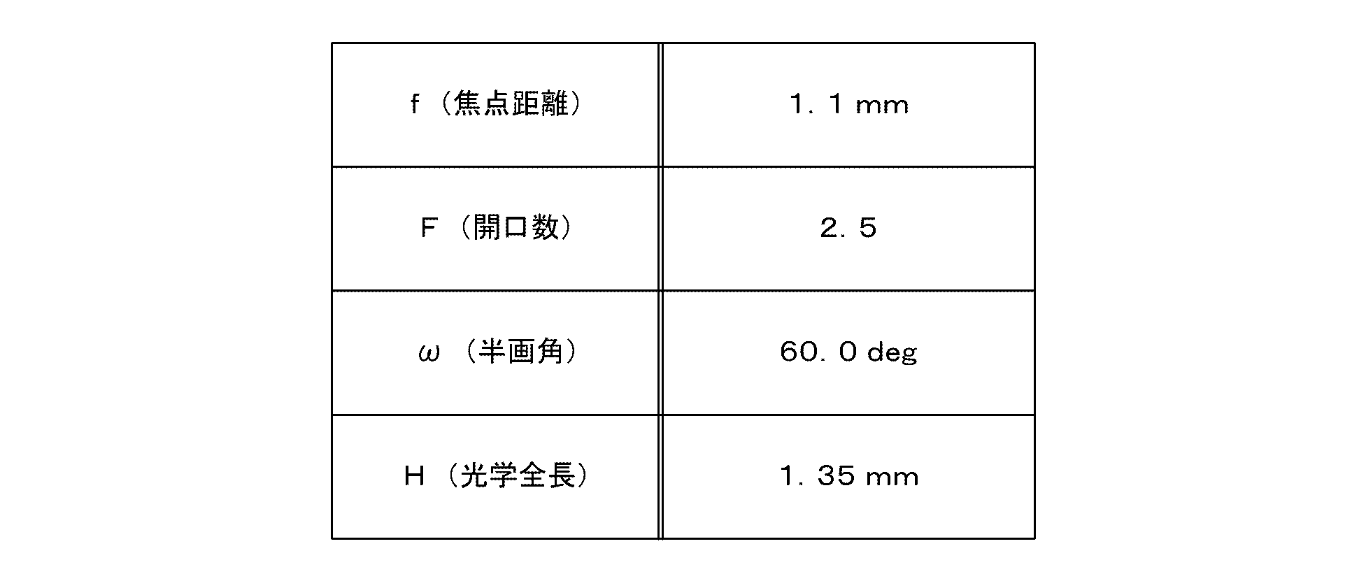
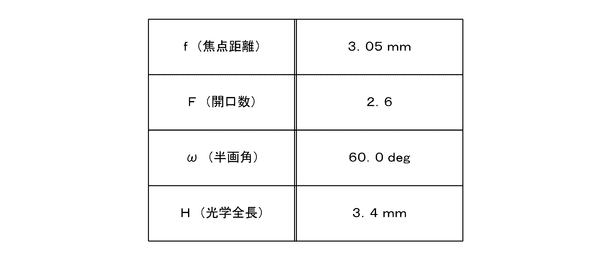
- Table 3 shows the focal length f, the F value F, the half angle of view ⁇ , and the optical total length H of Numerical Example 1.
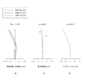
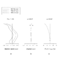
- FIG. 3 is a diagram of various types of aberration of the imaging lens according to the first embodiment of the present technology.
- a is a spherical aberration diagram (chromatic aberration diagram)
- b is an astigmatism diagram (field curvature diagram)
- c is a distortion diagram (distortion diagram).
- the dotted line shows the value at the d line (wavelength 587.56 nm)
- the solid line shows the e line (wavelength 546.07 nm)
- the alternate long and short dash line shows the value at the H ⁇ line (wavelength 486.13 nm).
- the solid line (X) shows the values on the sagittal image plane
- the broken line (Y) shows the values on the meridional image plane.
- the solid line shows the value at the d line. The same applies to the following spherical aberration diagram, astigmatism diagram, and distortion diagram.
- the second embodiment is a numerical example of a CMOS image sensor for full HD (1920 ⁇ 1080 pixels) of 1/7 size and 1.12 ⁇ m pitch.
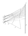
- FIG. 4 is a diagram showing a lens configuration of an image pickup device according to the second embodiment of the present technology.
- the imaging lens in the second embodiment is similar to the first embodiment described above, in order from the object side, the first lens L11 having a negative refractive power and the second lens having a positive refractive power. It is composed of L12 and a third lens L13 having a negative refractive power. These first to third lenses (L11 to L13) are arranged without an air gap, and constitute one group of triplet lenses. However, the lens shapes of the first to third lenses (L11 to L13) are different from those in the above-described first embodiment.
- Table 4 shows lens data of Numerical Example 2 in which specific numerical values are applied to the imaging lens according to the second embodiment.
- the mating surface (second surface), the bonding surface (third surface) of the second lens L12 and the third lens L13, and the image-side surface (fourth surface) of the third lens L13 are aspherical.
- the conical constant K of each of these surfaces, the 4th, 6th, 8th, 10th, 12th, 14th, 16th, 18th and 20th aspherical coefficients A, B , C, D, E, F, G, H and J are shown in Table 5.
- Table 6 shows the focal length f, the F value F, the half angle of view ⁇ , and the optical total length H of the second numerical example.
- FIG. 5 is a diagram of various aberrations of the imaging lens according to the second embodiment of the present technology.
- a is a spherical aberration diagram (chromatic aberration diagram)
- b is an astigmatism diagram (field curvature diagram)
- c is a distortion diagram (distortion diagram).
- the third embodiment is a numerical example of a CMOS image sensor for 1M size, 8M (3264 ⁇ 2448 pixels) with a pitch of 1.12 ⁇ m.
- the third embodiment With the size assumed in the third embodiment, it becomes difficult to perform aberration correction in the entire area by the lens of the first group configuration. For this reason, in the third embodiment, another independent short lens having a concave action is provided after the first lens group consisting of three lenses. That is, in order to obtain the desired optical characteristics, an extremely small size to about 1/5 size or 1/6 size is a range that can be configured with only the one-group lens, and for sizes larger than that, a configuration in which a lens is further added is useful. it is conceivable that.
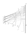
- FIG. 6 is a diagram showing a lens configuration of an image pickup device according to the third embodiment of the present technology.
- the imaging lens in the third embodiment is similar to the first embodiment described above, in order from the object side, the first lens L11 having a negative refractive power and the second lens having a positive refractive power. It is composed of L12 and a third lens L13 having a negative refractive power. These first to third lenses (L11 to L13) are arranged without an air gap, and constitute one group of triplet lenses.
- a fourth lens L14 which is arranged between the image pickup lens and the image pickup element 118 with air interposed therebetween. ..
- the fourth lens L14 is a biconcave lens having a negative refractive power.
- Table 7 shows lens data of Numerical Example 3 in which specific numerical values are applied to the imaging lens according to the third embodiment.
- the cemented surface (third surface) of the third lens L13, the image-side surface of the third lens L13 (fourth surface), and both surfaces of the fourth lens L14 (fifth surface and sixth surface) are aspherical surfaces. It is formed.
- Table 8 shows the conical constant K of each of these surfaces and the fourth-order, sixth-order, eighth-order, and tenth-order aspherical surface coefficients A, B, C, and D.
- Table 9 shows the focal length f, the F value F, the half angle of view ⁇ , and the optical total length H of the third numerical example.
- FIG. 7 is a diagram of various types of aberration of the imaging lens according to the third embodiment of the present technology.
- a is a spherical aberration diagram (chromatic aberration diagram)
- b is an astigmatism diagram (field curvature diagram)
- c is a distortion aberration diagram (distortion diagram).
- Table 10 shows each value in the numerical examples 1 to 3 of the first to third embodiments. As is clear from this value, it is understood that the conditional expressions (a) to (d) are satisfied. Further, as shown in each aberration diagram, it is understood that various aberrations are well-balanced at the wide-angle end and the telephoto end.
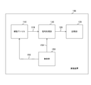
- FIG. 8 is a diagram showing an example in which the image pickup lens according to the first to third embodiments of the present technology is applied to the image pickup apparatus 100.
- the imaging device 100 for example, a mobile phone (including a smartphone), a mobile PC (Personal Computer), a wearable device, a scanner, a surveillance camera, an action cam, a video camera, a digital camera, or the like is assumed.
- the image pickup apparatus 100 includes an image pickup device 110, a signal processing unit 120, a recording unit 130, and a control unit 150.
- the image pickup device 110 has an image pickup function, and includes the image pickup lens according to the first to third embodiments and an image pickup element 118 that converts an optical image formed by the image pickup lens into an electrical signal.
- This imaging device 110 can cause image distortion due to optical distortion in the entire optical system.
- the image signal captured by the image capturing device 110 is supplied to the signal processing unit 120 via the signal line 119.
- the signal processing unit 120 performs signal processing such as analog-digital conversion on the image signal picked up by the image pickup device 110.
- the signal processing unit 120 converts the output signal from the image sensor 118 into a digital signal.
- the signal processing unit 120 also performs various signal processing such as noise removal, image quality correction, and conversion into luminance/color difference signals. As this signal processing, for example, optical distortion correction is performed on the output of the image pickup device 110.
- the image signal subjected to the signal processing by the signal processing unit 120 is supplied to the recording unit 130 via the signal line 129.
- the recording unit 130 records the image signal supplied from the signal processing unit 120 on a recording medium.
- the control unit 150 controls each unit of the imaging device 100.
- the control unit 150 controls the imaging device 110 according to a user's operation or the like to capture an image.
- the control unit 150 also controls the signal processing unit 120 to perform signal processing in synchronization with image capturing.
- the control signal from the control unit 150 is supplied to the signal processing unit 120 and the image pickup device 110 via the signal lines 119 and 158.
- the imaging device 100 may further include a display unit, and the captured image may be displayed on the display unit.
- the image pickup apparatus 100 may further include an interface, and may transmit an image signal to an external device via the interface.
- the aspheric first to third lenses (L11 to L13) that are bonded together without an air gap and the image sensor 118 to which the cover glass 117 is bonded are included.
- the performance can be improved, and a wide angle and a low profile can be realized.
- the one-group configuration eliminates the need for assembling the lenses individually, and there is no lens factor, for example, tilt due to burrs, eccentricity due to uneven lens diameter, tilt due to clogging in the barrel, and the like, and good productivity is achieved. Further, there is no need for assembling lenses or assembling a diaphragm, and there are few error factors.
- the first lens and the third lens are biconcave lenses, the optical path passing through the lens is longer in the periphery than in the center, and the field curvature can be efficiently corrected.
- the lens configuration is the negative group start, the peripheral light amount drop becomes gentler than the cosine fourth law, which is advantageous for the peripheral light amount.
- the factor of reflection (ghost) is small, and only two coats are required.
- the present optical system is adopted on the premise of distortion correction, it is possible to design with high resolution. Further, by utilizing the refraction of the cover glass 117 attached in front of the image pickup element 118, an image pickup lens having a large emission angle can be used effectively.
- the present technology may have the following configurations.
- An imaging lens including first to third lenses arranged in order without sandwiching air from the object side toward the image plane side, and each surface having an aspherical shape.
- An image pickup device comprising: an image pickup element, which is arranged on the image plane side of the image pickup lens and has a cover glass attached to the image pickup plane without an air gap.
- the first lens is a negative lens
- the second lens is a positive lens
- the imaging device according to (1), wherein the third lens is a negative lens.
- f focal length of lens system R1: radius of curvature of the first surface on the object side.
- b 0.05 ⁇ R2/f ⁇ 5
- f focal length of lens system R2: radius of curvature of second surface (5)
- the image pickup device according to any one of (1) to (4), wherein the image pickup lens satisfies the following conditional expression (c).
- the imaging device according to any one of (1) to (5), wherein the imaging lens satisfies the following conditional expression (d).
- the imaging device according to any one of 1.
- the image pickup device according to any one of (1) to (7), further including a fourth lens arranged with air sandwiched between the image pickup lens and the image pickup element.
- An image pickup lens including first to third lenses arranged in order from the object side toward the image plane side without sandwiching air and each surface having an aspherical shape, and on the image plane side of the image pickup lens.
- An image pickup device provided with an image pickup device arranged and having a cover glass attached to an image pickup surface without an air gap,
- An image pickup apparatus comprising: a signal processing unit that performs a predetermined signal process on an output of the image pickup device.
- the image pickup device has optical distortion in the entire optical system, The image processing apparatus according to (9), wherein the signal processing unit corrects the optical distortion with respect to the output of the imaging device.
- image pickup apparatus 100 image pickup apparatus 110 image pickup device L11 first lens L12 second lens L13 third lens L14 fourth lens 117 cover glass 118 image pickup element 120 signal processing section 130 recording section 150 control section
Landscapes
- Physics & Mathematics (AREA)
- General Physics & Mathematics (AREA)
- Optics & Photonics (AREA)
- Engineering & Computer Science (AREA)
- Multimedia (AREA)
- Signal Processing (AREA)
- Lenses (AREA)
- Studio Devices (AREA)
Abstract
1群構成を基本とするレンズにおいて、性能を向上させ、広角および低背化を図る。 撮像レンズは、第1乃至第3レンズを備える。これら第1乃至第3レンズは、物体側から像面側に向かって空気を挟まず順番に配置される。第1乃至第3レンズのそれぞれの面は、非球面形状を有する。撮像素子は、撮像レンズの像面側に配置される。撮像素子の撮像面には、カバーガラスが空気間隔なしに貼り付けられている。撮像レンズと撮像素子との間には、他のレンズを配置してもよい。
Description
本技術は、撮像デバイスに関する。詳しくは、撮像レンズを備える撮像デバイスおよび撮像装置に関する。
近年のモバイル機器やPC等に搭載される撮像機器には、高解像度、ローコスト、小型化が強く求められている。CCDやCMOS等の撮像素子のセルピッチが劇的に小さくなり、光学系には、従来よりも光学収差、特に、軸上色収差を抑えた高い結像性能が要求される。ここでは、特に、モバイル機器やウェアラブル機器用の小型撮像素子に着目する。小型撮像装置用の撮像レンズは、個々のレンズが小さくなり、プラスチック成型の際にレンズの外周部に出るバリに起因するレンズの傾きや、組み立て時に出る小さな傾きですら、性能を大きく劣化させる要因となっている。そのため、なるべく1群で、何らかの張り合わせや積み重ねを用い、撮像レンズを構成することが有用である。そのため、1群構成により諸収差の減少を図る光学ユニットおよび撮像装置が一例として提案されている(例えば、特許文献1参照。)。
上述の従来技術では、1群構成により諸収差の減少を図っている。しかしながら、上述の従来技術では、色収差のため軸上で解像度が低下し、非点収差のため周辺で解像度が劣化するという問題があり、また、F値、半画角、光学長などの面で性能上、十分とはいえない。
本技術はこのような状況に鑑みて生み出されたものであり、1群構成を基本とするレンズにおいて、性能を向上させ、広角および低背化を図ることを目的とする。
本技術は、上述の問題点を解消するためになされたものであり、その第1の側面は、物体側から像面側に向かって空気を挟まず順番に配置されてそれぞれの面が非球面形状を有する第1乃至第3レンズを備える撮像レンズと、上記撮像レンズの像面側に配置されてカバーガラスが空気間隔なしに撮像面に貼り付けられている撮像素子とを具備する撮像デバイスである。これにより、撮像デバイスの性能を向上させ、広角および低背化させるという作用をもたらす。
また、この第1の側面において、上記第1レンズは負レンズであり、上記第2レンズは正レンズであり、上記第3レンズは負レンズであるように構成してもよい。
また、この第1の側面において、上記撮像レンズが、以下の条件式(a)を満たすようにしてもよい。
条件式(a): -10≦R1/f≦-0.1
但し、fはレンズ系の焦点距離、R1は物体側第1面の曲率半径とする。
条件式(a): -10≦R1/f≦-0.1
但し、fはレンズ系の焦点距離、R1は物体側第1面の曲率半径とする。
また、この第1の側面において、上記撮像レンズが以下の条件式(b)を満たすようにしてもよい。
条件式(b): 0.05≦R2/f≦5
但し、fはレンズ系の焦点距離、R2は第2面の曲率半径とする。
条件式(b): 0.05≦R2/f≦5
但し、fはレンズ系の焦点距離、R2は第2面の曲率半径とする。
また、この第1の側面において、上記撮像レンズが以下の条件式(c)を満たすようにしてもよい。
条件式(c): -5≦R3/f≦-0.05
但し、fはレンズ系の焦点距離、R3は第3面の曲率半径とする。
条件式(c): -5≦R3/f≦-0.05
但し、fはレンズ系の焦点距離、R3は第3面の曲率半径とする。
また、この第1の側面において、上記撮像レンズが以下の条件式(d)を満たすようにしてもよい。
条件式(d): 1≦TT/Ym≦3
但し、Ymは最大像高、TTは光学全長とする。
条件式(d): 1≦TT/Ym≦3
但し、Ymは最大像高、TTは光学全長とする。
また、この第1の側面において、上記カバーガラスは、入射光の最大主光線入射角が35°を超え、上記入射光を屈折させて上記撮像面への出射角を5°以上緩和するようにしてもよい。
また、この第1の側面において、上記撮像レンズと上記撮像素子との間に空気を挟んで配置される第4レンズをさらに具備してもよい。
また、本技術の第2の側面は、物体側から像面側に向かって空気を挟まず順番に配置されてそれぞれの面が非球面形状を有する第1乃至第3レンズを備える撮像レンズと、上記撮像レンズの像面側に配置されてカバーガラスが空気間隔なしに撮像面に貼り付けられている撮像素子とを備える撮像デバイスと、上記撮像デバイスの出力に対して所定の信号処理を行う信号処理部とを具備する撮像装置である。これにより、撮像装置の性能を向上させ、広角および低背化させるという作用をもたらす。
また、この第2の側面において、上記撮像デバイスは、光学系全体で光学ディストーションを有し、上記信号処理部は、上記撮像デバイスの出力に対して上記光学ディストーションの補正を行うようにしてもよい。
以下、本技術を実施するための形態(以下、実施の形態と称する)について説明する。説明は以下の順序により行う。
1.第1の実施の形態(数値実施例1)
2.第2の実施の形態(数値実施例2)
3.第3の実施の形態(数値実施例3)
4.適用例(撮像装置)
1.第1の実施の形態(数値実施例1)
2.第2の実施の形態(数値実施例2)
3.第3の実施の形態(数値実施例3)
4.適用例(撮像装置)
以下の各表や説明において示した記号の意味等については、下記に示す通りである。すなわち、「R」は曲率半径を示す。面番号iに対応する「d」は物体側から数えて第i番目の面と第i+1番目の面との間の軸上面間隔を示す。「nd」は物体側に面を有する硝材または素材のd線(波長587.6nm)に対する屈折率を示す。「νd」は物体側に第i面を有する硝材または素材のd線に対するアッベ数を示す。そして、曲率半径に関し「INFINITY」は、当該面が平面であることを示す。また、面番号における「STO」は、当該面が開口絞りになっていることを示す。また、「f」は焦点距離を示す。「F」はF値(Fナンバー、開口数)を示す。「ω」は半画角を示す。「H」は光学全長を示す。
また、各実施の形態において用いられる撮像レンズには、上述のようにレンズ面が非球面によって構成されるものがある。レンズ面の頂点から光軸方向の距離(サグ量)を「x」、光軸と垂直な方向の高さを「y」、レンズ頂点での近軸曲率(1/r)を「c」、円錐(コーニック)定数を「K」とすると、
x=cy2/(1+(1-(1+K)c2y2)1/2)
+Ay4+By6+Cy8+Dy10+Ey12+Fy14
+Gy16+Hy18+Jy20
によって定義されるものとする。なお、A、B、C、D、E、F、G、HおよびJは、それぞれ第4次、第6次、第8次、第10次、第12次、第14次、第16次、第18次および第20次の非球面係数である。
+Ay4+By6+Cy8+Dy10+Ey12+Fy14
+Gy16+Hy18+Jy20
によって定義されるものとする。なお、A、B、C、D、E、F、G、HおよびJは、それぞれ第4次、第6次、第8次、第10次、第12次、第14次、第16次、第18次および第20次の非球面係数である。
この単焦点レンズは、例えば携帯電話(スマートフォンも含む)やモバイルPC、ウェアラブル機器等の小型情報端末機器などに搭載される小型撮像装置に代表されるような機器に搭載されて使用されるものを想定する。
この単焦点レンズの結像面には、例えばCCD(Charge Coupled Device)やCMOS(Complementary Metal Oxide Semiconductor)などの撮像素子が配置されることを想定する。また、像側レンズ群の像側面と結像面の間には、樹脂またはガラスで構成されるカバーガラスや赤外カットフィルタやローパスフィルタなどの他、光学部材が配置されていてもよい。
本開示の撮像デバイスは、物体側から像面側に向かって空気を挟まず順番に配置されてそれぞれの面が非球面形状を有する第1乃至第3レンズを備える撮像レンズと、前記撮像レンズの像面側に配置されてカバーガラスが空気間隔なしに撮像面に貼り付けられている撮像素子とを具備する。このように、第1乃至第3レンズを、空気を挟まずに配置することにより、光学全長を短くすることができる。
また、本開示の撮像デバイスにおいて、第1レンズは負レンズであり、第2レンズは正レンズであり、第3レンズは負レンズであることが想定される。
また、本開示の撮像デバイスにおいて、撮像レンズが、以下の条件式(a)乃至(c)を満たすことが想定される。
条件式(a): -10≦R1/f≦-0.1
条件式(b): 0.05≦R2/f≦5
条件式(c): -5≦R3/f≦-0.05
但し、
f: レンズ系の焦点距離
R1: 物体側第1面の曲率半径
R2: 第2面の曲率半径
R3: 第3面の曲率半径
とする。
条件式(a): -10≦R1/f≦-0.1
条件式(b): 0.05≦R2/f≦5
条件式(c): -5≦R3/f≦-0.05
但し、
f: レンズ系の焦点距離
R1: 物体側第1面の曲率半径
R2: 第2面の曲率半径
R3: 第3面の曲率半径
とする。
また、本開示の撮像デバイスにおいて、撮像レンズが、以下の条件式(d)を満たすことが想定される。
条件式(d): 1≦TT/Ym≦3
但し、
Ym: 最大像高(mm)
TT: 光学全長(mm)
とする。
条件式(d): 1≦TT/Ym≦3
但し、
Ym: 最大像高(mm)
TT: 光学全長(mm)
とする。
また、本開示の撮像デバイスにおいて、カバーガラスは、入射光の最大主光線入射角が35°を超え、入射光を屈折させて前記撮像面への出射角を5°以上緩和することが想定される。すなわち、撮像レンズにより出射された高い主光線入射角(CRA:Chief Ray Angle)を、カバーガラスの屈折を利用して緩和するものである。これにより、小型・低背で明るい広角レンズを実現することができる。
また、本開示の撮像デバイスにおいて、撮像レンズと撮像素子との間に空気を挟んで配置される第4レンズをさらに具備することも想定される。
上述の条件式は、以下で取り扱う数値実施例1乃至3に共通するものであり、必要に応じて適宜採用することで、個々の撮像素子または撮像装置に適したより好ましい結像性能とコンパクトな光学系が実現される。
本開示の撮像デバイスの基本構成は、物体側から像面側に向かって空気を挟まず順番に配置された、物体側第1レンズと第2レンズと第3レンズが空気間隔を持たずに配置された1群のトリプレットレンズを構成するものである。第1レンズは両凹形状を有する。第2レンズは両凸形状を有する。第3レンズは、面形状がうねるが、およそ両凹形状を有する。撮像レンズからの出射光線は、中心部から周辺部に向かって、主光線入射角が大きくなるようになっている。像側は、カバーガラスが空気間隔なしに撮像面に貼りつけられている撮像素子を有する。撮像レンズを出射した光線は、カバーガラスで屈折して、主光線角度が緩和され、撮像素子に入射して、望ましい光学特性となる。以下に、条件式の作用について説明する。
条件式(a)は、物体側第1レンズの物体側第1面の曲率半径に関する条件式で、この面が物体側に凹形状になることを表している。1群構成でより良いカメラ特性を得るためには、中心より周辺の方がレンズの中を通る光路が長くなるようにし、像面湾曲を効率よく補正することが必要であり、下限は補正不足、上限は可補正となるためにこの式が必要である。
条件式(b)は、物体側第1レンズの像側と第2レンズの物体側の接合部の曲率半径に関する条件式であり、軸外色収差の補正を効率よく行うために必要となる。通常の張り合わせレンズでは、分散の少ない硝材を使った凸レンズと分散の多い硝材を使った凹レンズを張り合わせ、色収差を補正して、結像性能を上げるが、それは、軸上の特性のみである。像高が高くなると、逆に特性が悪化する。カメラレンズは、その逆のものも組みあわせ、軸外の特性を出す。そのときの分散の差は少なくする。ここでは、物体側の入射第1面に波長分散の大きいアッベ数の小さい硝材を設けると、波長分散の効果が大きくなり過ぎて補正できなくなるために、入射面にアッベ数が大きい硝材が最適となる。また、条件式(a)について説明した理由により、凹の形状となり、やや分散の多い硝材が次の面に設けられて、凸の形状となって軸外収差色を補正する。下限は、曲率半径が小さくなりすぎて、誤差が性能に大きく影響を及ぼすため、製造上の限界として規定される。上限は、色収差の補正不足となり、全体性能に影響するため、この値となる。
条件式(c)は、物体側第2レンズの像側と第3レンズの物体側の接合部の曲率半径に関する条件式であり、軸上色収差低減と、像面湾曲を効率よく補正するために必要となる。通常の張り合わせレンズでは、分散の少ない硝材を使った凸レンズと分散の多い硝材を使った凹レンズを張り合わせて、色収差を補正して、結像性能を上げる。本開示の撮像デバイスにおいても同様の手法を採用する。また、それと同時に、第3レンズが凹形状になることにより、中心より周辺の方がレンズの中を通る光路が長くなるようにし、像面湾曲を補正する。下限は、曲率が緩くなり、全体性能が落ちるため、その下限として規定される。上限は、曲率半径が小さくなり過ぎて、誤差が性能に大きく影響を及ぼすため、製造上の限界として規定される。
条件式(d)は、最大像高と光学全長の関係を表しており、下限は、物体側第1レンズに負の作用があることにより収差補正を行うため、光学全長を短くすることができる限界があることに起因する。上限は、本開示の撮像デバイスの使用目的に起因する。使用目的が小型モジュールのために、光学長が長いものを目的としない。これにより、条件式(d)に示した値が上限となる。
<1.第1の実施の形態>
この第1の実施の形態は、1/10.49サイズ、1.12μmピッチのHD(1296×816画素)用CMOSイメージセンサの数値実施例である。
この第1の実施の形態は、1/10.49サイズ、1.12μmピッチのHD(1296×816画素)用CMOSイメージセンサの数値実施例である。
[レンズ構成]
図1は、本技術の第1の実施の形態における撮像デバイスのレンズ構成を示す図である。
図1は、本技術の第1の実施の形態における撮像デバイスのレンズ構成を示す図である。
この第1の実施の形態における撮像レンズは、物体側より順に、負の屈折力を有する第1レンズL11と、正の屈折力を有する第2レンズL12と、負の屈折力を有する第3レンズL13とから構成される。これら第1乃至第3レンズ(L11乃至L13)は、空気間隔を持たずに配置され、1群のトリプレットレンズを構成する。
また、この第1の実施の形態における撮像デバイスは、撮像レンズの像面側に配置される撮像素子118を備える。この撮像素子118の撮像面には、カバーガラス117が空気間隔なしに貼り付けられている。カバーガラス117は、撮像素子118を保護するための透明体であり、接着剤または充填剤により空気を介さずに撮像素子118の像面に貼り付けられている。これは、例えば、ウエハーレベルCSP(Wafer level Chip Size Package) 技術により実現することができる。
第1レンズL11は、両凹形状でνdが60である。第2レンズL12は、両凸形状でνdが49.2である。第3レンズL13は、面形状がうねるが、およそ両凹形状で、νdが30である。第2レンズL12および第3レンズL13によって、軸上の色収差を補正している。また、第1レンズL11および第2レンズL12によって、軸外の色収差を補正している。第1レンズL11および第3レンズL13が両凹形状で、周辺に行くに従って、光路長が長くなるようになっており、像面湾曲収差を補正するようになっている。
撮像レンズからの出射光線は、中心部から周辺部に向かって、主光線入射角が大きくなるようになっている。像側は、カバーガラス117が空気間隔なしに撮像面に貼りつけられている撮像素子118を有する。撮像レンズを出射した光線は、カバーガラス117で屈折して、主光線角度が緩和され、撮像素子118に入射して、望ましい光学特性となる。
図2は、本技術の実施の形態におけるカバーガラス117の断面構成例を示す図である。
この例では、最大像高部で撮像レンズの出射の主光線が50.5°であるものと想定している。撮像レンズの出射の主光線は、カバーガラス117の屈折によって31.5°まで曲げられ、撮像素子118に入射する。この撮像レンズは全画角120°と非常に広角であり、光学全長が1.35mmと非常に低背に抑えられていることが分かる。
カバーガラス117の空気に対する相対屈折率をnCGとし、入射角をRin、屈折角をRoutとすると、これらの間には、スネルの法則より次の関係式が成立する。なお、接着剤や充填剤の屈折率は、カバーガラス117と同程度とする。
sin(Rin)/sin(Rout)=nCG
sin(Rin)/sin(Rout)=nCG
上式において、カバーガラス117の屈折角Routは、入射角Rinより5度以上小さいものとする。上述のように、カバーガラス117は撮像素子118の像面に貼り付けられているため、上式の屈折角Routで屈折した主光線が、そのままの角度で像面に入射される。このため、像面に対する主光線最大入射角(=Rout)は、カバーガラス117に対する最大主光線入射角(=Rin)よりも5度以上小さくなる。すなわち、カバーガラス117における屈折により、撮像レンズからの主光線の光軸に対する最大出射角(=Rin)が5度以上緩和される。例えば、相対屈折率nCGは約1.5であり、上式より、最大出射角は32度まで緩和される。
撮像素子118は、撮像レンズを介して受光した光を光電変換して画像信号を生成するものである。この撮像素子118は、例えば、CCDやCMOSにより構成される。この撮像素子118において、画素間の混色が生じない最大の入射角は、瞳補正を考慮しても、例えば、35度前後であると考えられる。上述のように、最大主光線出射角は、カバーガラス117により5度以上、緩和される。このため、カバーガラス117への最大主光線出射角が35度より大きな広角の撮像レンズを用いても、像面に対する入射角を許容限度である35度以下に抑制することができる。
[撮像レンズの緒元]
表1に、第1の実施の形態における撮像レンズに具体的数値を適用した数値実施例1のレンズデータを示す。

表1に、第1の実施の形態における撮像レンズに具体的数値を適用した数値実施例1のレンズデータを示す。
この第1の実施の形態における撮像レンズでは、第1レンズL11の物体側の面(第1面)、第1レンズL11と第2レンズL12の貼り合せ面(第2面)、第2レンズL12と第3レンズL13の貼り合せ面(第3面)、第3レンズL13の像側の面(第4面)は、非球面に形成される。これら各面の円錐定数K、第4次、第6次、第8次、第10次、第12次、第14次、第16次、第18次および第20次の非球面係数A、B、C、D、E、F、G、HおよびJを、表2に示す。なお、表2および以下の非球面係数を示す表において「E-i」は10を底とする指数表現、すなわち、「10-i」を表しており、例えば、「0.12345E-05」は「0.12345×10⁻⁵」を表している。
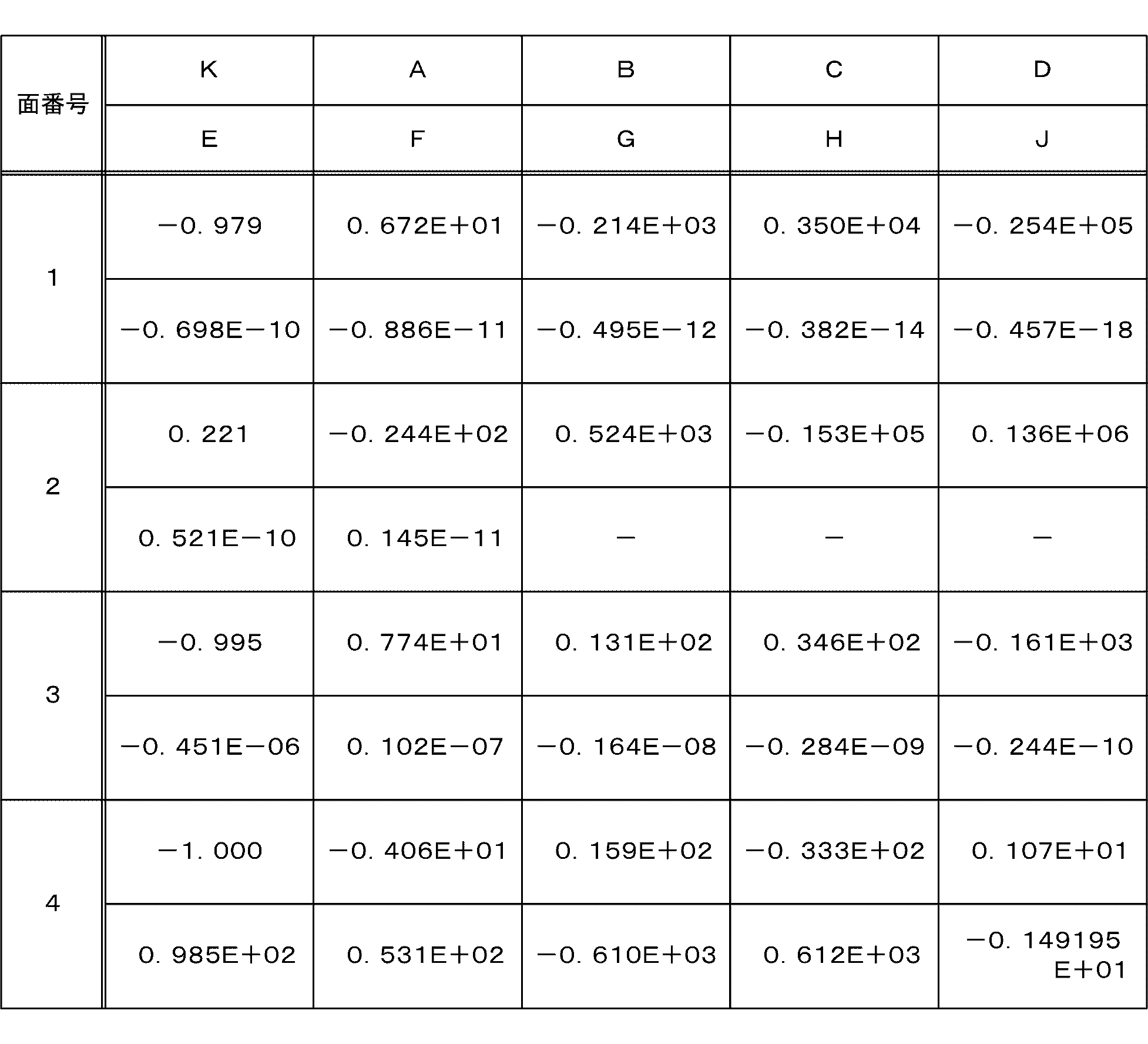
表3に、この数値実施例1の焦点距離f、F値F、半画角ωおよび光学全長Hを示す。
[撮像レンズの収差]
図3は、本技術の第1の実施の形態における撮像レンズの諸収差図である。同図において、aは球面収差図(色収差図)、bは非点収差図(像面湾曲図)、cは歪曲収差図(ディスト―ション図)をそれぞれ示している。
図3は、本技術の第1の実施の形態における撮像レンズの諸収差図である。同図において、aは球面収差図(色収差図)、bは非点収差図(像面湾曲図)、cは歪曲収差図(ディスト―ション図)をそれぞれ示している。
なお、球面収差図において、点線はd線(波長587.56nm)、実線はe線(波長546.07nm)、一点鎖線はHβ線(波長486.13nm)における値を示す。また、非点収差図において、実線(X)はサジタル像面、破線(Y)はメリディオナル像面における値を示す。また、歪曲収差図において、実線はd線における値を示すものである。以下の球面収差図、非点収差図および歪曲収差図においても同様である。
各収差図から、数値実施例1は諸収差が良好に補正され、優れた結像性能を有していることが明らかである。
<2.第2の実施の形態>
この第2の実施の形態は、1/7サイズ、1.12μmピッチのフルHD(1920×1080画素)用CMOSイメージセンサの数値実施例である。
この第2の実施の形態は、1/7サイズ、1.12μmピッチのフルHD(1920×1080画素)用CMOSイメージセンサの数値実施例である。
[レンズ構成]
図4は、本技術の第2の実施の形態における撮像デバイスのレンズ構成を示す図である。
図4は、本技術の第2の実施の形態における撮像デバイスのレンズ構成を示す図である。
この第2の実施の形態における撮像レンズは、上述の第1の実施の形態と同様に、物体側より順に、負の屈折力を有する第1レンズL11と、正の屈折力を有する第2レンズL12と、負の屈折力を有する第3レンズL13とから構成される。これら第1乃至第3レンズ(L11乃至L13)は、空気間隔を持たずに配置され、1群のトリプレットレンズを構成する。ただし、第1乃至第3レンズ(L11乃至L13)のレンズ形状は、上述の第1の実施の形態とは異なっている。
カバーガラス117が空気間隔なしに撮像面に貼りつけられている撮像素子118を有する点についても、上述の第1の実施の形態と同様と同様である。
[撮像レンズの緒元]
表4に、第2の実施の形態における撮像レンズに具体的数値を適用した数値実施例2のレンズデータを示す。
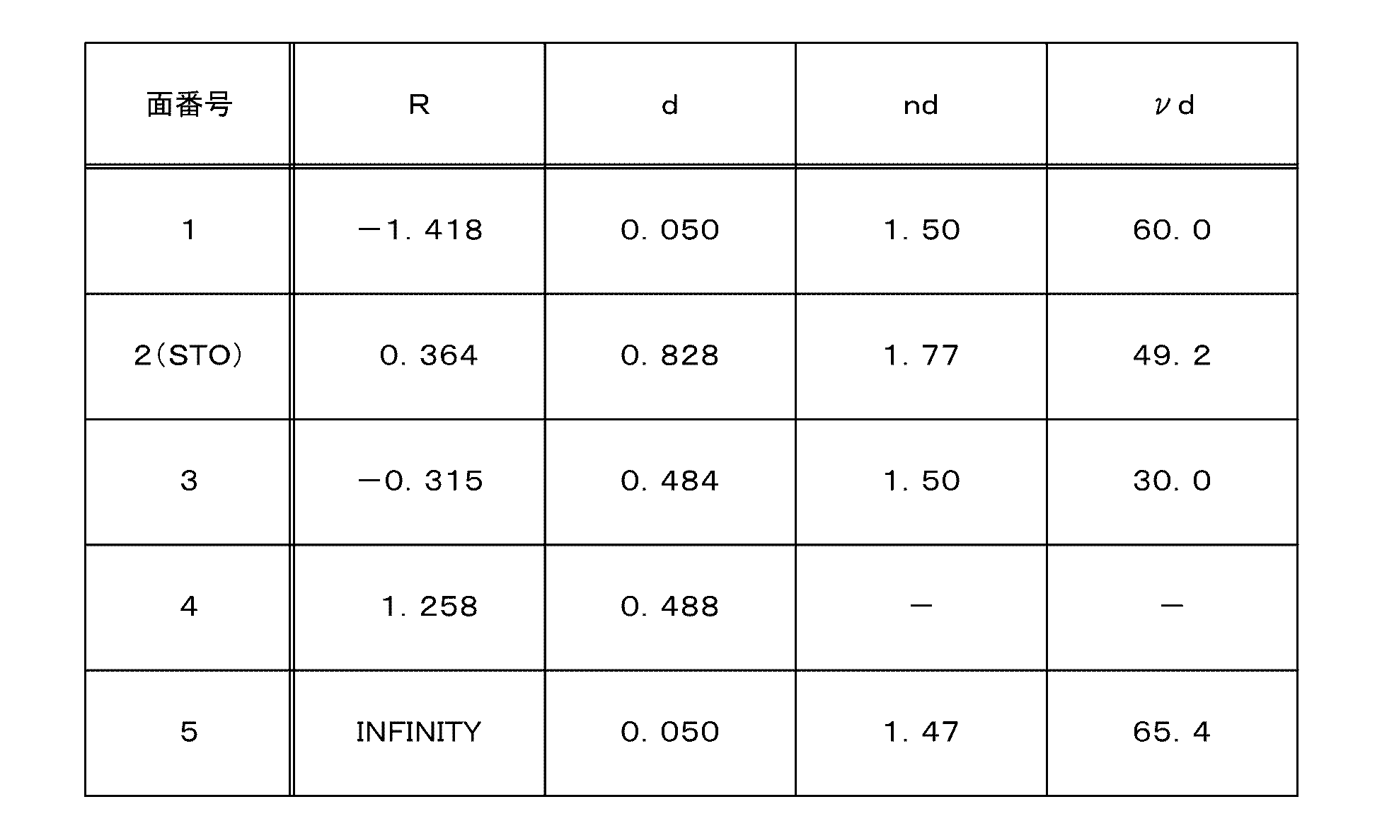
表4に、第2の実施の形態における撮像レンズに具体的数値を適用した数値実施例2のレンズデータを示す。
この第2の実施の形態における撮像レンズでは、上述の第1の実施の形態と同様に、第1レンズL11の物体側の面(第1面)、第1レンズL11と第2レンズL12の貼り合せ面(第2面)、第2レンズL12と第3レンズL13の貼り合せ面(第3面)、第3レンズL13の像側の面(第4面)は、非球面に形成される。これら各面の円錐定数K、第4次、第6次、第8次、第10次、第12次、第14次、第16次、第18次および第20次の非球面係数A、B、C、D、E、F、G、HおよびJを、表5に示す。
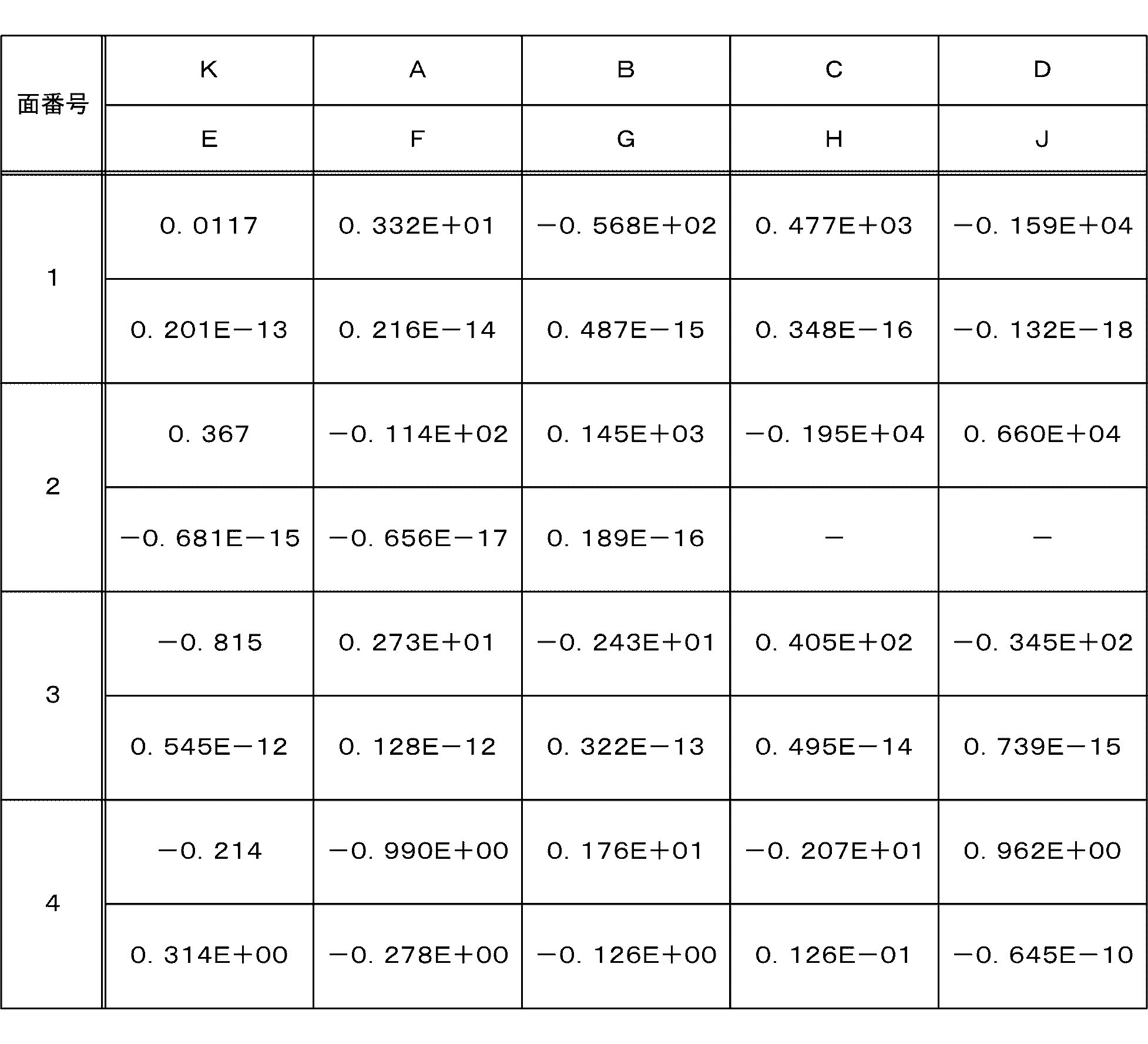
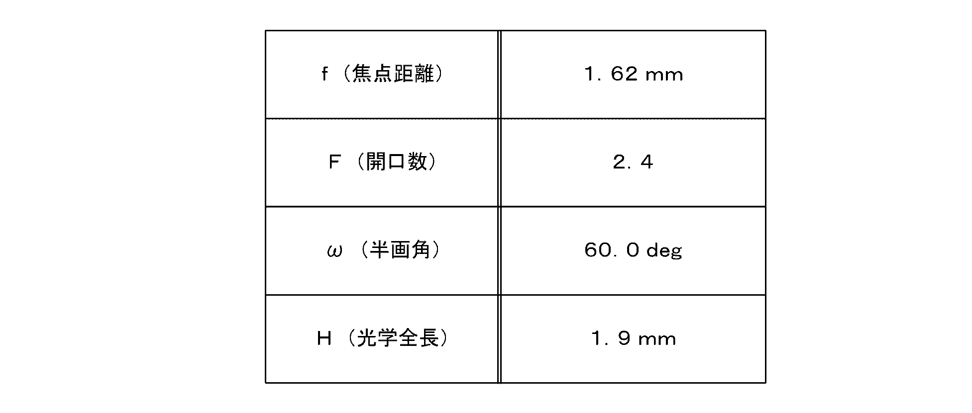
表6に、この数値実施例2の焦点距離f、F値F、半画角ωおよび光学全長Hを示す。
[撮像レンズの収差]
図5は、本技術の第2の実施の形態における撮像レンズの諸収差図である。同図において、aは球面収差図(色収差図)、bは非点収差図(像面湾曲図)、cは歪曲収差図(ディスト―ション図)をそれぞれ示している。
図5は、本技術の第2の実施の形態における撮像レンズの諸収差図である。同図において、aは球面収差図(色収差図)、bは非点収差図(像面湾曲図)、cは歪曲収差図(ディスト―ション図)をそれぞれ示している。
各収差図から、数値実施例2は諸収差が良好に補正され、優れた結像性能を有していることが明らかである。
<3.第3の実施の形態>
この第3の実施の形態は、1/4サイズ、1.12μmピッチの8M(3264×2448画素)用CMOSイメージセンサの数値実施例である。
この第3の実施の形態は、1/4サイズ、1.12μmピッチの8M(3264×2448画素)用CMOSイメージセンサの数値実施例である。
この第3の実施の形態において想定するサイズでは、1群構成のレンズによって収差補正を全域で行うことは難しくなってくる。そのため、この第3の実施の形態では、1群3枚レンズの後に、もう一枚の独立した凹作用の短レンズを設ける。すなわち、望ましい光学特性を得るには、極小サイズから1/5サイズまたは1/6サイズ程度が1群レンズのみで構成できる範囲であり、それ以上のサイズではさらにレンズを追加した構成が有用であると考えられる。
[レンズ構成]
図6は、本技術の第3の実施の形態における撮像デバイスのレンズ構成を示す図である。
図6は、本技術の第3の実施の形態における撮像デバイスのレンズ構成を示す図である。
この第3の実施の形態における撮像レンズは、上述の第1の実施の形態と同様に、物体側より順に、負の屈折力を有する第1レンズL11と、正の屈折力を有する第2レンズL12と、負の屈折力を有する第3レンズL13とから構成される。これら第1乃至第3レンズ(L11乃至L13)は、空気間隔を持たずに配置され、1群のトリプレットレンズを構成する。
ただし、この第3の実施の形態では、第1乃至第3レンズ(L11乃至L13)に加えて、撮像レンズと撮像素子118との間に空気を挟んで配置される第4レンズL14をさらに備える。この第4レンズL14は、負の屈折力を有する両凹レンズである。
カバーガラス117が空気間隔なしに撮像面に貼りつけられている撮像素子118を有する点についても、上述の第1の実施の形態と同様と同様である。
[撮像レンズの緒元]
表7に、第3の実施の形態における撮像レンズに具体的数値を適用した数値実施例3のレンズデータを示す。
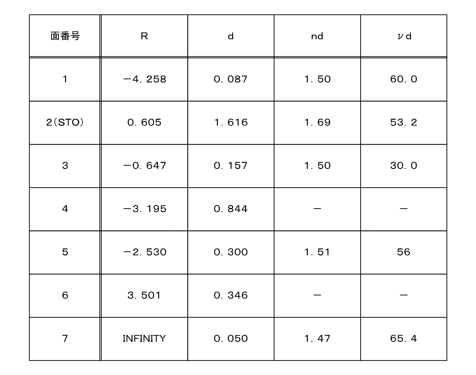
表7に、第3の実施の形態における撮像レンズに具体的数値を適用した数値実施例3のレンズデータを示す。
この第3の実施の形態における撮像レンズでは、第1レンズL11の物体側の面(第1面)、第1レンズL11と第2レンズL12の貼り合せ面(第2面)、第2レンズL12と第3レンズL13の貼り合せ面(第3面)、第3レンズL13の像側の面(第4面)、第4レンズL14の両面(第5面および第6面)は、非球面に形成される。これら各面の円錐定数K、第4次、第6次、第8次および第10次の非球面係数A、B、CおよびDを、表8に示す。

表9に、この数値実施例3の焦点距離f、F値F、半画角ωおよび光学全長Hを示す。
[撮像レンズの収差]
図7は、本技術の第3の実施の形態における撮像レンズの諸収差図である。同図において、aは球面収差図(色収差図)、bは非点収差図(像面湾曲図)、cは歪曲収差図(ディスト―ション図)をそれぞれ示している。
図7は、本技術の第3の実施の形態における撮像レンズの諸収差図である。同図において、aは球面収差図(色収差図)、bは非点収差図(像面湾曲図)、cは歪曲収差図(ディスト―ション図)をそれぞれ示している。
各収差図から、数値実施例3は諸収差が良好に補正され、優れた結像性能を有していることが明らかである。
[条件式のまとめ]
表10に第1乃至3の実施の形態の数値実施例1乃至3における各値を示す。この値からも明らかなように、条件式(a)乃至(d)を満足することがわかる。また、各収差図に示すように、広角端および望遠端において、各種収差もバランスよく補正されていることがわかる。
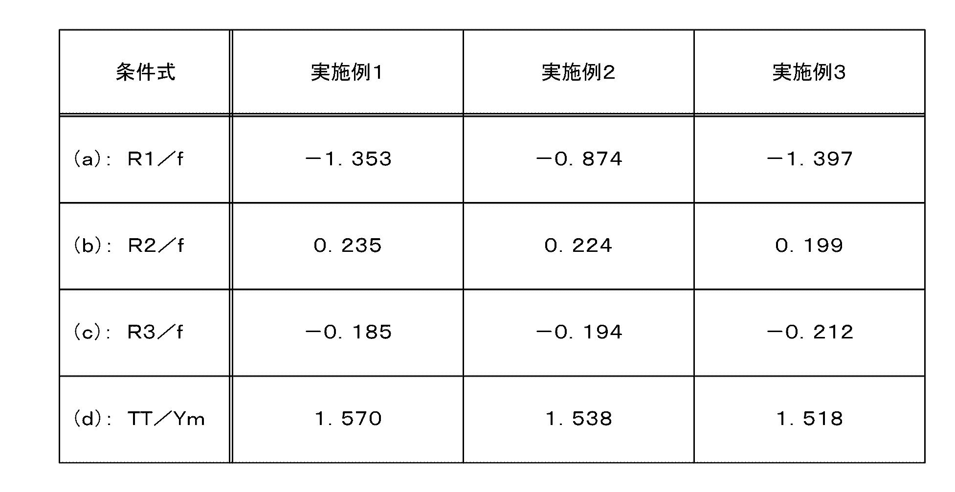
表10に第1乃至3の実施の形態の数値実施例1乃至3における各値を示す。この値からも明らかなように、条件式(a)乃至(d)を満足することがわかる。また、各収差図に示すように、広角端および望遠端において、各種収差もバランスよく補正されていることがわかる。
<4.適用例>
[撮像装置の構成]
図8は、本技術の第1乃至3の実施の形態による撮像レンズを撮像装置100に適用した例を示す図である。この撮像装置100として、例えば、携帯電話(スマートフォンも含む)やモバイルPC(Personal Computer)、ウェアラブル機器、スキャナー、監視カメラ、アクションカム、ビデオカメラおよびデジタルカメラなどが想定される。この撮像装置100は、撮像デバイス110と、信号処理部120と、記録部130と、制御部150とを備えている。
[撮像装置の構成]
図8は、本技術の第1乃至3の実施の形態による撮像レンズを撮像装置100に適用した例を示す図である。この撮像装置100として、例えば、携帯電話(スマートフォンも含む)やモバイルPC(Personal Computer)、ウェアラブル機器、スキャナー、監視カメラ、アクションカム、ビデオカメラおよびデジタルカメラなどが想定される。この撮像装置100は、撮像デバイス110と、信号処理部120と、記録部130と、制御部150とを備えている。
撮像デバイス110は、撮像機能を担うものであり、第1乃至3の実施の形態による撮像レンズと、その撮像レンズにより形成された光学像を電気的信号に変換する撮像素子118とを備える。この撮像デバイス110は、光学系全体で光学ディストーションによる画像のひずみを生じ得る。この撮像デバイス110において撮像された画像信号は、信号線119を介して信号処理部120に供給される。
信号処理部120は、撮像デバイス110によって撮像された画像信号に対してアナログ-デジタル変換等の信号処理を行うものである。この信号処理部120は、撮像素子118からの出力信号に対してデジタル信号への変換を行う。また、この信号処理部120は、ノイズ除去、画質補正、輝度・色差信号への変換等の各種の信号処理を行う。この信号処理として、例えば、撮像デバイス110の出力に対して光学ディストーションの補正を行う。この信号処理部120によって信号処理が施された画像信号は、信号線129を介して記録部130に供給される。
記録部130は、信号処理部120から供給された画像信号を記録媒体に記録するものである。
制御部150は、撮像装置100の各部を制御するものである。この制御部150は、ユーザの操作などに従って撮像デバイス110を制御して、画像を撮像させる。また、制御部150は、信号処理部120を制御して、画像の撮像に同期して信号処理を行わせる。この制御部150からの制御信号は、信号線119および158を介して、信号処理部120および撮像デバイス110に供給される。
なお、撮像装置100は、表示部をさらに備え、撮像した画像を、その表示部に表示してもよい。また、撮像装置100は、インターフェースをさらに備え、そのインターフェースを介して外部の装置に画像信号を送信してもよい。
このように、本技術の実施の形態では、空気間隔を持たずに貼り合せた非球面の第1乃至第3レンズ(L11乃至L13)と、カバーガラス117が貼り付けられた撮像素子118とを備えることにより、性能を向上させ、広角および低背化を実現することができる。
すなわち、解像度と感度が高く、全画角が120°という、非常に広角で1乃至2mm程度の光学全長の1群レンズのカメラを提供することができる。また、1群構成により、レンズを個々に組み立てる必要がなく、レンズ要因、例えばバリ起因のチルト、レンズ径不揃いによる偏心、バレルでの詰まりによるチルト等が無く、生産性が良好である。また、レンズ同士の組立てや絞りの組立てが不要であり、誤差要因が少ない。また、第1レンズおよび第3レンズが両凹レンズであるため、中心より周辺の方がレンズの中を通る光路が長くなり、像面湾曲を効率良く補正することができる。また、レンズ構成が負群始まりであるため、周辺光量落ちがコサイン4乗則より緩やかになり、周辺光量に有利である。また、屈折率差のあるレンズと空気の界面が2個しかなく、反射(ゴースト)要因が少なく、また、コートが2面で済む。また、歪補正を前提として本光学系を採用すると、解像度の高い設計をすることができる。また、撮像素子118の前に張り付けたカバーガラス117の屈折を利用することにより、出射角の大きい撮像レンズを使いこなすことができる。
なお、上述の実施の形態は本技術を具現化するための一例を示したものであり、実施の形態における事項と、特許請求の範囲における発明特定事項とはそれぞれ対応関係を有する。同様に、特許請求の範囲における発明特定事項と、これと同一名称を付した本技術の実施の形態における事項とはそれぞれ対応関係を有する。ただし、本技術は実施の形態に限定されるものではなく、その要旨を逸脱しない範囲において実施の形態に種々の変形を施すことにより具現化することができる。
なお、本明細書に記載された効果はあくまで例示であって、限定されるものではなく、また、他の効果があってもよい。
なお、本技術は以下のような構成もとることができる。
(1)物体側から像面側に向かって空気を挟まず順番に配置されてそれぞれの面が非球面形状を有する第1乃至第3レンズを備える撮像レンズと、
前記撮像レンズの像面側に配置されてカバーガラスが空気間隔なしに撮像面に貼り付けられている撮像素子と
を具備する撮像デバイス。
(2)前記第1レンズは負レンズであり、
前記第2レンズは正レンズであり、
前記第3レンズは負レンズである
前記(1)に記載の撮像デバイス。
(3)前記撮像レンズが、以下の条件式(a)を満たす前記(1)または(2)に記載の撮像デバイス。
条件式(a): -10≦R1/f≦-0.1
但し、
f: レンズ系の焦点距離
R1: 物体側第1面の曲率半径
とする。
(4)前記撮像レンズが以下の条件式(b)を満たす前記(1)から(3)のいずれかに記載の撮像デバイス。
条件式(b): 0.05≦R2/f≦5
但し、
f: レンズ系の焦点距離
R2: 第2面の曲率半径
とする。
(5)前記撮像レンズが以下の条件式(c)を満たす前記(1)から(4)のいずれかに記載の撮像デバイス。
条件式(c): -5≦R3/f≦-0.05
但し、
f: レンズ系の焦点距離
R3: 第3面の曲率半径
とする。
(6)前記撮像レンズが以下の条件式(d)を満たす前記(1)から(5)のいずれかに記載の撮像デバイス。
条件式(d): 1≦TT/Ym≦3
但し、
Ym: 最大像高
TT: 光学全長
とする。
(7)前記カバーガラスは、入射光の最大主光線入射角が35°を超え、前記入射光を屈折させて前記撮像面への出射角を5°以上緩和する
前記(1)から(6)のいずれかに記載の撮像デバイス。
(8)前記撮像レンズと前記撮像素子との間に空気を挟んで配置される第4レンズをさらに具備する
前記(1)から(7)のいずれかに記載の撮像デバイス。
(9)物体側から像面側に向かって空気を挟まず順番に配置されてそれぞれの面が非球面形状を有する第1乃至第3レンズを備える撮像レンズと、前記撮像レンズの像面側に配置されてカバーガラスが空気間隔なしに撮像面に貼り付けられている撮像素子とを備える撮像デバイスと、
前記撮像デバイスの出力に対して所定の信号処理を行う信号処理部と
を具備する撮像装置。
(10)前記撮像デバイスは、光学系全体で光学ディストーションを有し、
前記信号処理部は、前記撮像デバイスの出力に対して前記光学ディストーションの補正を行う
前記(9)に記載の撮像装置。
(1)物体側から像面側に向かって空気を挟まず順番に配置されてそれぞれの面が非球面形状を有する第1乃至第3レンズを備える撮像レンズと、
前記撮像レンズの像面側に配置されてカバーガラスが空気間隔なしに撮像面に貼り付けられている撮像素子と
を具備する撮像デバイス。
(2)前記第1レンズは負レンズであり、
前記第2レンズは正レンズであり、
前記第3レンズは負レンズである
前記(1)に記載の撮像デバイス。
(3)前記撮像レンズが、以下の条件式(a)を満たす前記(1)または(2)に記載の撮像デバイス。
条件式(a): -10≦R1/f≦-0.1
但し、
f: レンズ系の焦点距離
R1: 物体側第1面の曲率半径
とする。
(4)前記撮像レンズが以下の条件式(b)を満たす前記(1)から(3)のいずれかに記載の撮像デバイス。
条件式(b): 0.05≦R2/f≦5
但し、
f: レンズ系の焦点距離
R2: 第2面の曲率半径
とする。
(5)前記撮像レンズが以下の条件式(c)を満たす前記(1)から(4)のいずれかに記載の撮像デバイス。
条件式(c): -5≦R3/f≦-0.05
但し、
f: レンズ系の焦点距離
R3: 第3面の曲率半径
とする。
(6)前記撮像レンズが以下の条件式(d)を満たす前記(1)から(5)のいずれかに記載の撮像デバイス。
条件式(d): 1≦TT/Ym≦3
但し、
Ym: 最大像高
TT: 光学全長
とする。
(7)前記カバーガラスは、入射光の最大主光線入射角が35°を超え、前記入射光を屈折させて前記撮像面への出射角を5°以上緩和する
前記(1)から(6)のいずれかに記載の撮像デバイス。
(8)前記撮像レンズと前記撮像素子との間に空気を挟んで配置される第4レンズをさらに具備する
前記(1)から(7)のいずれかに記載の撮像デバイス。
(9)物体側から像面側に向かって空気を挟まず順番に配置されてそれぞれの面が非球面形状を有する第1乃至第3レンズを備える撮像レンズと、前記撮像レンズの像面側に配置されてカバーガラスが空気間隔なしに撮像面に貼り付けられている撮像素子とを備える撮像デバイスと、
前記撮像デバイスの出力に対して所定の信号処理を行う信号処理部と
を具備する撮像装置。
(10)前記撮像デバイスは、光学系全体で光学ディストーションを有し、
前記信号処理部は、前記撮像デバイスの出力に対して前記光学ディストーションの補正を行う
前記(9)に記載の撮像装置。
100 撮像装置
110 撮像デバイス
L11 第1レンズ
L12 第2レンズ
L13 第3レンズ
L14 第4レンズ
117 カバーガラス
118 撮像素子
120 信号処理部
130 記録部
150 制御部
110 撮像デバイス
L11 第1レンズ
L12 第2レンズ
L13 第3レンズ
L14 第4レンズ
117 カバーガラス
118 撮像素子
120 信号処理部
130 記録部
150 制御部
Claims (10)
- 物体側から像面側に向かって空気を挟まず順番に配置されてそれぞれの面が非球面形状を有する第1乃至第3レンズを備える撮像レンズと、
前記撮像レンズの像面側に配置されてカバーガラスが空気間隔なしに撮像面に貼り付けられている撮像素子と
を具備する撮像デバイス。 - 前記第1レンズは負レンズであり、
前記第2レンズは正レンズであり、
前記第3レンズは負レンズである
請求項1記載の撮像デバイス。 - 前記撮像レンズが、以下の条件式(a)を満たす請求項1記載の撮像デバイス。
条件式(a): -10≦R1/f≦-0.1
但し、
f: レンズ系の焦点距離
R1: 物体側第1面の曲率半径
とする。 - 前記撮像レンズが以下の条件式(b)を満たす請求項1記載の撮像デバイス。
条件式(b): 0.05≦R2/f≦5
但し、
f: レンズ系の焦点距離
R2: 第2面の曲率半径
とする。 - 前記撮像レンズが以下の条件式(c)を満たす請求項1記載の撮像デバイス。
条件式(c): -5≦R3/f≦-0.05
但し、
f: レンズ系の焦点距離
R3: 第3面の曲率半径
とする。 - 前記撮像レンズが以下の条件式(d)を満たす請求項1記載の撮像デバイス。
条件式(d): 1≦TT/Ym≦3
但し、
Ym: 最大像高
TT: 光学全長
とする。 - 前記カバーガラスは、入射光の最大主光線入射角が35°を超え、前記入射光を屈折させて前記撮像面への出射角を5°以上緩和する
請求項1記載の撮像デバイス。 - 前記撮像レンズと前記撮像素子との間に空気を挟んで配置される第4レンズをさらに具備する
請求項1記載の撮像デバイス。 - 物体側から像面側に向かって空気を挟まず順番に配置されてそれぞれの面が非球面形状を有する第1乃至第3レンズを備える撮像レンズと、前記撮像レンズの像面側に配置されてカバーガラスが空気間隔なしに撮像面に貼り付けられている撮像素子とを備える撮像デバイスと、
前記撮像デバイスの出力に対して所定の信号処理を行う信号処理部と
を具備する撮像装置。 - 前記撮像デバイスは、光学系全体で光学ディストーションを有し、
前記信号処理部は、前記撮像デバイスの出力に対して前記光学ディストーションの補正を行う
請求項9記載の撮像装置。
Priority Applications (1)
| Application Number | Priority Date | Filing Date | Title |
|---|---|---|---|
| US17/297,020 US12181632B2 (en) | 2018-12-05 | 2019-11-15 | Imaging device and imaging apparatus |
Applications Claiming Priority (2)
| Application Number | Priority Date | Filing Date | Title |
|---|---|---|---|
| JP2018-228040 | 2018-12-05 | ||
| JP2018228040A JP2020091385A (ja) | 2018-12-05 | 2018-12-05 | 撮像デバイスおよび撮像装置 |
Publications (1)
| Publication Number | Publication Date |
|---|---|
| WO2020116132A1 true WO2020116132A1 (ja) | 2020-06-11 |
Family
ID=70975427
Family Applications (1)
| Application Number | Title | Priority Date | Filing Date |
|---|---|---|---|
| PCT/JP2019/044927 Ceased WO2020116132A1 (ja) | 2018-12-05 | 2019-11-15 | 撮像デバイスおよび撮像装置 |
Country Status (3)
| Country | Link |
|---|---|
| US (1) | US12181632B2 (ja) |
| JP (1) | JP2020091385A (ja) |
| WO (1) | WO2020116132A1 (ja) |
Citations (6)
| Publication number | Priority date | Publication date | Assignee | Title |
|---|---|---|---|---|
| JPH09236746A (ja) * | 1995-12-26 | 1997-09-09 | Ricoh Co Ltd | 小型の広角レンズ |
| JP2008285377A (ja) * | 2007-05-18 | 2008-11-27 | Panasonic Corp | 接合光学素子 |
| WO2009069467A1 (ja) * | 2007-11-29 | 2009-06-04 | Konica Minolta Opto, Inc. | 撮像レンズ、撮像装置及び携帯端末 |
| WO2011148822A1 (ja) * | 2010-05-28 | 2011-12-01 | オリンパスメディカルシステムズ株式会社 | 結像光学系および撮像装置 |
| JP2017040743A (ja) * | 2015-08-19 | 2017-02-23 | ソニー株式会社 | 撮像デバイス、および、撮像装置 |
| JP2017167253A (ja) * | 2016-03-15 | 2017-09-21 | 日立マクセル株式会社 | 撮像レンズ系及び撮像装置 |
Family Cites Families (7)
| Publication number | Priority date | Publication date | Assignee | Title |
|---|---|---|---|---|
| US5760973A (en) | 1995-12-26 | 1998-06-02 | Ricoh Company, Ltd. | Compact wide-angle lens system |
| US6271975B1 (en) * | 1998-04-09 | 2001-08-07 | Asulab S.A. | Light collecting optical device forming a multiple focal distance lens |
| JP3926380B1 (ja) * | 2006-12-07 | 2007-06-06 | マイルストーン株式会社 | 撮像レンズ |
| JP2010091881A (ja) * | 2008-10-09 | 2010-04-22 | Olympus Imaging Corp | 結像光学系及びそれを有する電子撮像装置 |
| JP5434450B2 (ja) | 2009-10-06 | 2014-03-05 | ソニー株式会社 | 光学ユニットおよび撮像装置 |
| TWM387263U (en) * | 2010-02-11 | 2010-08-21 | E Pin Optical Industry Co Ltd | Optical imaging lens and the array thereof |
| JP6873741B2 (ja) * | 2017-02-24 | 2021-05-19 | オリンパス株式会社 | 撮像装置 |
-
2018
- 2018-12-05 JP JP2018228040A patent/JP2020091385A/ja active Pending
-
2019
- 2019-11-15 WO PCT/JP2019/044927 patent/WO2020116132A1/ja not_active Ceased
- 2019-11-15 US US17/297,020 patent/US12181632B2/en active Active
Patent Citations (6)
| Publication number | Priority date | Publication date | Assignee | Title |
|---|---|---|---|---|
| JPH09236746A (ja) * | 1995-12-26 | 1997-09-09 | Ricoh Co Ltd | 小型の広角レンズ |
| JP2008285377A (ja) * | 2007-05-18 | 2008-11-27 | Panasonic Corp | 接合光学素子 |
| WO2009069467A1 (ja) * | 2007-11-29 | 2009-06-04 | Konica Minolta Opto, Inc. | 撮像レンズ、撮像装置及び携帯端末 |
| WO2011148822A1 (ja) * | 2010-05-28 | 2011-12-01 | オリンパスメディカルシステムズ株式会社 | 結像光学系および撮像装置 |
| JP2017040743A (ja) * | 2015-08-19 | 2017-02-23 | ソニー株式会社 | 撮像デバイス、および、撮像装置 |
| JP2017167253A (ja) * | 2016-03-15 | 2017-09-21 | 日立マクセル株式会社 | 撮像レンズ系及び撮像装置 |
Also Published As
| Publication number | Publication date |
|---|---|
| US20220026676A1 (en) | 2022-01-27 |
| US12181632B2 (en) | 2024-12-31 |
| JP2020091385A (ja) | 2020-06-11 |
Similar Documents
| Publication | Publication Date | Title |
|---|---|---|
| CN111045191B (zh) | 光学系统、透镜单元以及摄像装置 | |
| CN109219766B (zh) | 摄像光学系统、透镜部件以及摄像装置 | |
| CN112114416B (zh) | 摄像镜头 | |
| JP5698872B2 (ja) | 撮像レンズおよび撮像レンズを備えた撮像装置 | |
| US9104013B2 (en) | Imaging lens | |
| JP4186560B2 (ja) | 超広角レンズ | |
| JP2015004842A (ja) | 撮像レンズ | |
| JP2004245982A (ja) | 撮像レンズ装置およびそれを備えた電子機器 | |
| WO2013175782A1 (ja) | 撮像レンズおよび撮像レンズを備えた撮像装置 | |
| KR102109934B1 (ko) | 촬영 렌즈 및 이를 구비한 촬영 장치 | |
| CN103718079A (zh) | 广角透镜、摄像光学装置及数码设备 | |
| JP2004163786A (ja) | 撮像レンズ | |
| JP4235007B2 (ja) | 撮像レンズ | |
| CN107924043A (zh) | 图像拾取装置和图像拾取设备 | |
| JP2005316010A (ja) | 撮像レンズ | |
| CN111338063A (zh) | 光学系统、镜头模组和电子设备 | |
| US7532416B2 (en) | Imaging lens, imaging unit and optical device | |
| US20060066748A1 (en) | Image pickup optical system and digital apparatus using the same | |
| JP2021179594A (ja) | 撮像光学系、レンズユニット及び撮像装置 | |
| JP2015161760A (ja) | 撮像レンズ | |
| US6775072B2 (en) | Single-focus lens | |
| CN115136051B (zh) | 成像透镜、照相机和移动信息终端设备 | |
| KR102008497B1 (ko) | 촬상 렌즈 시스템 | |
| JP4442184B2 (ja) | 撮像レンズ | |
| JP2006301221A (ja) | 撮像レンズ |
Legal Events
| Date | Code | Title | Description |
|---|---|---|---|
| 121 | Ep: the epo has been informed by wipo that ep was designated in this application |
Ref document number: 19892374 Country of ref document: EP Kind code of ref document: A1 |
|
| NENP | Non-entry into the national phase |
Ref country code: DE |
|
| 122 | Ep: pct application non-entry in european phase |
Ref document number: 19892374 Country of ref document: EP Kind code of ref document: A1 |