WO2020116108A1 - 排気浄化装置 - Google Patents
排気浄化装置 Download PDFInfo
- Publication number
- WO2020116108A1 WO2020116108A1 PCT/JP2019/044490 JP2019044490W WO2020116108A1 WO 2020116108 A1 WO2020116108 A1 WO 2020116108A1 JP 2019044490 W JP2019044490 W JP 2019044490W WO 2020116108 A1 WO2020116108 A1 WO 2020116108A1
- Authority
- WO
- WIPO (PCT)
- Prior art keywords
- exhaust gas
- exhaust
- introduction path
- reducing agent
- casing
- Prior art date
- Legal status (The legal status is an assumption and is not a legal conclusion. Google has not performed a legal analysis and makes no representation as to the accuracy of the status listed.)
- Ceased
Links
Images


Classifications
-
- B—PERFORMING OPERATIONS; TRANSPORTING
- B01—PHYSICAL OR CHEMICAL PROCESSES OR APPARATUS IN GENERAL
- B01D—SEPARATION
- B01D53/00—Separation of gases or vapours; Recovering vapours of volatile solvents from gases; Chemical or biological purification of waste gases, e.g. engine exhaust gases, smoke, fumes, flue gases, aerosols
- B01D53/34—Chemical or biological purification of waste gases
- B01D53/92—Chemical or biological purification of waste gases of engine exhaust gases
- B01D53/94—Chemical or biological purification of waste gases of engine exhaust gases by catalytic processes
-
- F—MECHANICAL ENGINEERING; LIGHTING; HEATING; WEAPONS; BLASTING
- F01—MACHINES OR ENGINES IN GENERAL; ENGINE PLANTS IN GENERAL; STEAM ENGINES
- F01N—GAS-FLOW SILENCERS OR EXHAUST APPARATUS FOR MACHINES OR ENGINES IN GENERAL; GAS-FLOW SILENCERS OR EXHAUST APPARATUS FOR INTERNAL-COMBUSTION ENGINES
- F01N3/00—Exhaust or silencing apparatus having means for purifying, rendering innocuous, or otherwise treating exhaust
- F01N3/08—Exhaust or silencing apparatus having means for purifying, rendering innocuous, or otherwise treating exhaust for rendering innocuous
- F01N3/10—Exhaust or silencing apparatus having means for purifying, rendering innocuous, or otherwise treating exhaust for rendering innocuous by thermal or catalytic conversion of noxious components of exhaust
- F01N3/24—Exhaust or silencing apparatus having means for purifying, rendering innocuous, or otherwise treating exhaust for rendering innocuous by thermal or catalytic conversion of noxious components of exhaust characterised by constructional aspects of converting apparatus
-
- Y—GENERAL TAGGING OF NEW TECHNOLOGICAL DEVELOPMENTS; GENERAL TAGGING OF CROSS-SECTIONAL TECHNOLOGIES SPANNING OVER SEVERAL SECTIONS OF THE IPC; TECHNICAL SUBJECTS COVERED BY FORMER USPC CROSS-REFERENCE ART COLLECTIONS [XRACs] AND DIGESTS
- Y02—TECHNOLOGIES OR APPLICATIONS FOR MITIGATION OR ADAPTATION AGAINST CLIMATE CHANGE
- Y02T—CLIMATE CHANGE MITIGATION TECHNOLOGIES RELATED TO TRANSPORTATION
- Y02T10/00—Road transport of goods or passengers
- Y02T10/10—Internal combustion engine [ICE] based vehicles
- Y02T10/12—Improving ICE efficiencies
Definitions
- the present invention relates to an exhaust purification device. More specifically, the present invention can reduce the retention of a reducing agent in an exhaust gas purification apparatus that includes a reducing catalyst that reduces a specific substance contained in exhaust gas with a reducing agent that contains a substance that is solid or liquid at room temperature.
- the present invention relates to an exhaust emission control device.
- Exhaust gas emitted from an internal combustion engine such as a diesel engine contains particulate matter (PM) such as soot and nitrogen oxides (NOx). Therefore, from the viewpoint of protecting the global environment, for example, a diesel particulate filter (DPF: Diesel Particulate Filter) and an exhaust purification device such as a reducing catalyst such as a selective catalytic reduction denitration device (SCR: Selective Reduction) are used.
- a diesel particulate filter Diesel Particulate Filter
- SCR selective catalytic reduction denitration device
- the reduction catalyst reduces a specific substance contained in exhaust gas by a reducing agent added on the upstream side thereof and converts it into a harmless substance.
- a selective catalytic reduction NOx removal device uses a reducing agent (for example, ammonia (NH 3 ), urea, urea water, etc.) that is added on the upstream side of NOx contained in exhaust gas as a harmless substance.
- a reducing agent for example, ammonia (NH 3 ), urea, urea water, etc.
- NH 3 ammonia
- urea water urea water
- the path from when the reducing agent is added to the exhaust gas to when it reaches the SCR is lengthened so that the reducing agent and the exhaust gas are sufficiently mixed, and It is desirable to extend the time required for the thermal decomposition of.
- the above problems are not limited to reducing agents containing urea (for example, urea water, etc.), but can occur in common with reducing agents containing substances that are solid at room temperature. Even when the reducing agent contains a substance that is liquid at room temperature, the reducing agent remaining without being used for the reduction of the target substance remains in the exhaust passage and reduces the cross-sectional area of the exhaust passage, for example. This may lead to an increase in pressure loss. In addition, depending on the structure of the reducing agent, there is a possibility that the reducing agent freezes in the exhaust passage during cold weather, resulting in deformation and/or damage of the exhaust passage.
- urea for example, urea water, etc.
- An exhaust gas purification apparatus including a reduction catalyst that purifies exhaust gas by reducing a specific substance contained in exhaust gas discharged from an internal combustion engine by a reducing agent containing a substance that is solid or liquid at room temperature as described above.
- a reduction catalyst that purifies exhaust gas by reducing a specific substance contained in exhaust gas discharged from an internal combustion engine by a reducing agent containing a substance that is solid or liquid at room temperature as described above.
- the present invention has been conceived to address the above-described problems, and reduction in an exhaust emission control device that includes a reduction catalyst that reduces a specific substance contained in exhaust gas with a reducing agent that includes a substance that is solid or liquid at room temperature.
- An object is to provide an exhaust emission control device that can reduce the retention of the agent.
- an exhaust gas purification device is an exhaust gas that includes a first purification portion, an introduction path, and a reducing agent addition portion. It is a purification device.
- the first purification unit includes a reduction catalyst that purifies the exhaust gas by reducing the first substance, which is a specific substance contained in the exhaust gas discharged from the internal combustion engine, with a reducing agent.
- the introduction path is arranged adjacent to the upstream side of the first purification section in the exhaust flow path, which is a path through which the exhaust flows, and is configured to guide the exhaust to the first purification section.
- the reducing agent addition unit is configured to add the reducing agent inside the introduction path.
- the reducing agent includes substances that are solid or liquid at room temperature.
- the introduction path is configured to guide the exhaust gas to the first purification unit via the second portion, which is a portion higher than the first portion in the operating state of the device of the present invention.
- the first portion is a portion where the reducing agent is added inside the introduction route.
- the second portion is a portion that is formed on the downstream side of the first portion and is higher than the first portion in the operating state of the device of the present invention.
- the introduction route may have a U-shape, S-shape, M-shape, spiral shape, or the like.
- the first purification unit may include a purification unit other than the reduction catalyst.
- the device of the present invention may further include a second purifying unit which is disposed on the upstream side of the introduction path and purifies the exhaust gas.
- the device of the present invention may be housed in a casing, and the casing may be filled with a heat insulating material, or configured to keep the first purifying section and the introduction path warm by the exhaust gas flowing inside. May be.
- the device of the present invention may further include a combustor for supplying combustion gas to the exhaust passage.
- the device of the present invention may further include a mixing member and/or a reactor in the middle of the exhaust flow path.
- the introduction path provided in the device of the present invention is the second portion which is a portion higher than the first portion on the downstream side of the first portion which is a portion to which the reducing agent is added inside the introduction passage in the operating state.
- the exhaust gas is configured to be guided to the first purification unit via the.
- the reducing agent used for the reduction of the target substance is increased (by promoting the thermal decomposition of urea) and the reducing agent retained inside the introduction route is reduced, so that the retention of the reducing agent in the device of the present invention is reduced. Can be reduced.
- an introduction path having a bent portion such as U-shape, S-shape, M-shape or spiral shape
- promotion of mixing of the reducing agent and exhaust gas and miniaturization of the device of the present invention, etc. Can be achieved.
- a casing for accommodating the device of the present invention and/or a combustor for supplying combustion gas to the exhaust passage for example, reduction used for reduction of a target substance (by promoting thermal decomposition of urea).
- the amount of the agent can be increased and the activity of the reduction catalyst can be increased.
- a mixing member and/or a reactor in the middle of the exhaust flow path, for example, to promote the mixing of the reducing agent and the exhaust gas (by promoting the thermal decomposition of urea) and to reduce the target substance
- the reducing agent used can be increased.
- FIG. 15 is a schematic perspective view showing a state in which only the outer wall on the inlet side of the casing is removed from the second embodiment device shown in FIG. 14.
- FIG. 15 is a schematic perspective view showing a state where all the outer walls of the casing have been removed from the device of the second embodiment shown in FIG. 14.
- FIG. 15 is a typical perspective view which shows the external appearance when the 2nd Example apparatus shown in FIG. 13 is observed from the opposite side of an inlet.
- FIG. 18 is a schematic perspective view showing a state in which only the outer wall on the side opposite to the inlet of the casing is removed from the device of the second embodiment shown in FIG. 17.
- FIG. 18 is a schematic perspective view showing a state in which all the outer walls of the casing have been removed from the second embodiment device shown in FIG. 17.
- It is a schematic diagram which shows an example of a structure of the 2nd Example apparatus which concerns on one modification.
- It is a typical front view showing an example of the composition of the exhaust-air-purification device (the device of the 3rd example) concerning the 3rd example of the present invention.
- FIG. 22 is a schematic perspective view showing an appearance when the device of Example 3 shown in FIG. 21 is observed from the inlet side.
- FIG. 22 is a schematic perspective view showing an appearance when the device of Example 3 shown in FIG. 21 is observed from the inlet side.
- FIG. 23 is a schematic perspective view showing a state in which only the outer wall on the inlet side of the casing is removed from the device of the third embodiment shown in FIG. 22.
- FIG. 23 is a schematic perspective view showing a state where all the outer walls of the casing have been removed from the device of the third embodiment shown in FIG. 22.
- FIG. 22 is a schematic perspective view showing an appearance when the device of Example 3 shown in FIG. 21 is observed from the side opposite to the inlet.
- FIG. 26 is a schematic perspective view showing a state in which only the outer wall on the side opposite to the inlet of the casing is removed from the third embodiment device shown in FIG. 25.
- FIG. 25 is a schematic perspective view showing a state in which only the outer wall on the side opposite to the inlet of the casing is removed from the third embodiment device shown in FIG. 25.
- 26 is a schematic perspective view showing a state where all the outer walls of the casing have been removed from the device of the third embodiment shown in FIG. 25. It is a schematic diagram which shows an example of a structure of the exhaust emission control device (4th Example apparatus) which concerns on 4th Example of this invention.
- first device an exhaust emission control device according to a first embodiment of the present invention
- the first device is an exhaust gas purification device that includes a first purification unit, an introduction path, and a reducing agent addition unit.
- the first purification unit includes a reduction catalyst that purifies the exhaust gas by reducing the first substance, which is a specific substance contained in the exhaust gas discharged from the internal combustion engine, with a reducing agent.
- the first purification unit may further include an exhaust purification unit other than the reduction catalyst (for example, an ammonia slip catalyst (ASC: Ammonia Slip Catalyst)). Further, as long as the reduction catalyst is disposed on the downstream side of the introduction path and is suitable for the exhaust gas purification function of each purification unit including the reduction catalyst, the reduction catalyst and the other exhaust gas purification units included in the first purification unit are not limited.
- the first purification unit also includes an exhaust purification unit other than the reduction catalyst, a plurality of the exhaust purification units may be arranged in parallel.
- the introduction path is arranged adjacent to the upstream side of the first purification section in the exhaust flow path, which is a path through which the exhaust flows, and is configured to guide the exhaust to the first purification section.
- the specific configuration of the introduction path is not particularly limited as long as it is possible to guide the exhaust gas discharged from the internal combustion engine to the first purification unit.
- the introduction path may be configured by a tubular member (pipe) such as a steel pipe, or by a manufacturing method of laminating a plurality of press-molded members (so-called “Monaca manufacturing method”). Good.
- the introduction path may be configured by a plate-shaped and/or gutter-shaped member attached to the outer wall or the inner wall of the first purification unit or another component.
- a labyrinth structure may be provided inside the introduction path to lengthen the exhaust stroke (path) in the introduction path.
- the reducing agent addition unit is configured to add the reducing agent inside the introduction route.
- the reducing agent includes a substance that is solid or liquid at room temperature.
- the specific configuration of the reducing agent addition section is not particularly limited as long as the reducing agent can be added inside the introduction route.
- the reducing agent addition unit can include, for example, an injection device that injects a liquid reducing agent into the introduction path.
- the first substance is nitrogen oxide
- the reducing agent contains urea (for example, urea water, etc.)
- the reducing catalyst is a selective catalytic reduction denitration device (SCR: Selective Catalytic Reduction).
- the introduction path is configured to guide the exhaust gas to the first purification unit via the second portion, which is a portion higher than the first portion in the operating state of the first device.
- the "operating state of the first device” refers to a state in which the first device is operably incorporated in a device or equipment in which an internal combustion engine to which the first device is applied is installed. As a specific example of such a state, for example, a state in which the first device is operably incorporated in a vehicle equipped with an internal combustion engine can be cited.
- the first part is the part where the reducing agent is added inside the introduction route.
- the reducing agent addition unit includes an injection device that injects a liquid reducing agent (for example, urea water) into the introduction path as described above, the reducing agent is injected into the introduction path by the injection device.
- the part is the first part.
- the second part is a part that is formed on the downstream side of the first part in the operating state of the first device and is higher than the first part.
- the introduction path in the operating state of the first device has, for example, an upwardly sloped portion toward the second portion on the downstream side of the first portion.
- This inclined portion does not necessarily have to be linear, and may be curved, for example, and may include a bent portion in the middle. Further, the shape of the inclined portion having such a bent portion may be two-dimensional, or may be three-dimensional as shown in Examples described later.
- the introduction path included in the first device necessarily has a sloped portion as long as it has a second portion that is formed on the downstream side of the first portion and is higher than the first portion in the operating state of the first device. There is no need. Specifically, even if at least a part of the portion that connects the first portion and the second portion in the introduction path extends in the vertical direction, as in the case where the introduction path has a stepped shape, for example. Good.
- the reducing agent is added to the inside of the introduction path at the first part and is pushed up to the second part higher than the first part along the flow of exhaust gas. Therefore, the reducing agent remaining without being used for the reduction of the target substance flows back from the high second portion on the downstream side to the low first portion on the upstream side due to the action of gravity, and by the new high temperature exhaust gas. It is heated and swept to the downstream side again. By repeating this, the reducing agent used for the reduction of the target substance increases and the reducing agent staying inside the introduction path decreases, so that the staying of the reducing agent in the first device can be reduced.
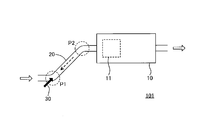
- FIG. 1 is a schematic diagram showing an example of the configuration of the first device.
- the first device 101 is an exhaust gas purification device that includes a first purification unit 10, an introduction path 20, and a reducing agent addition unit 30 (indicated by a black arrow).
- the first purification unit 10 includes a reduction catalyst 11 that purifies exhaust gas by reducing a first substance, which is a specific substance contained in exhaust gas discharged from an internal combustion engine (not shown), with a reducing agent.
- the exhaust flow in the first device is indicated by the white arrow.
- the introduction path 20 is arranged adjacent to the upstream side of the first purification section 10 in the exhaust flow path, which is a path through which the exhaust flows, and is configured to guide the exhaust to the first purification section 10.
- the first substance is nitrogen oxide (NOx)
- the reducing agent is urea water
- the reducing catalyst is the selective catalytic reduction.
- SCR denitration device
- the reducing agent addition unit 30 is configured to add urea water as a reducing agent inside the introduction path 20.
- the injection device (not shown) included in the reducing agent addition unit 30 injects urea water into the introduction path 20, and the thermal decomposition of urea produces NH 3 which is a reducing agent.
- the introduction path 20 passes through the second portion (the area P2 surrounded by the broken line) which is a portion higher than the first portion (the area P1 surrounded by the broken line) in the operating state of the first device 101.
- the exhaust gas is configured to be guided to the first purification unit 10.
- the heat of the exhaust gas thermally decomposes urea to generate NH 3 , and in the SCR as the reduction catalyst included in the first purification unit 10. It is consumed as a reducing agent in the reduction reaction of NOx to N 2 .
- the urea remaining without being thermally decomposed adheres to the inner wall of the exhaust passage on the upstream side of the reduction catalyst, etc. Then, it may stay in the exhaust passage.
- the urea that has accumulated as described above is cooled and deposited when the internal combustion engine is not operating, etc., the cross-sectional area of the exhaust passage is reduced and the flow of exhaust is obstructed, and the pressure loss of the exhaust passage is reduced. It may increase. Further, there is a possibility that urea deposits that have fallen off the inner wall of the exhaust flow path are carried downstream by the exhaust gas and collide with the reduction catalyst to damage the reduction catalyst and reduce the exhaust purification performance.
- the reducing agent (urea water) is added to the inside of the introduction path 20 at the first portion P1, and the reducing agent (urea water) is added along the flow of the exhaust gas more than the first portion P1. It is pushed up to the high second part P2. Therefore, as described above, even if the residual urea that has not been thermally decomposed and remains in the introduction path 20 is moved from the relatively high second portion P2 to the relatively low first portion P1 by the action of gravity. Urea (or urea water) is returned (backflow from the downstream side to the upstream side) (see the broken arrow in FIG. 1 ).
- the urea that has not been used for the reduction of NOx as the target substance and remains in the introduction path 20 flows back from the high second site on the downstream side to the low first site on the upstream side by the action of gravity. , Is heated by new high temperature exhaust gas, and is again swept to the downstream side (second portion P2 side).
- the thermal decomposition of urea is promoted, the amount of urea used for NOx reduction increases, and the amount of urea retained inside the introduction path 20 decreases, so that the retention of urea in the first device 101 can be reduced. ..
- the introduction passage provided in the first device is the second portion which is a portion higher than the first portion on the downstream side of the first portion which is a portion to which the reducing agent is added inside the introduction passage in the operating state.
- the exhaust gas is configured to be guided to the first purification unit via the.
- the reducing agent used for the reduction of the target substance increases and the reducing agent staying inside the introduction route decreases, so that the staying of the reducing agent in the first device can be reduced.
- the reducing agent remaining without being used for the reduction of the target substance stays in the exhaust passage, and causes problems such as an increase in pressure loss in the exhaust passage, damage to the reduction catalyst, and damage to the exhaust passage. It is possible to reduce the possibility that
- the introduction path in the operating state of the first device may have, for example, an upwardly sloped portion that is downstream of the first portion and heads toward the second portion. It does not have to be linear, and may be curved, for example, and may include a bent portion in the middle.
- the device or the equipment and/or the device of the present invention may be applied.
- the introduction path itself may need to be bent for the purpose of avoiding interference between other members constituting the introduction path and the introduction path. That is, the introduction path included in the first device may include at least one bent portion.
- the second device is the above-described first device and is an exhaust gas purification device in which the introduction path has at least one bent portion.
- the bent portion formed in the introduction path included in the second device is not limited to the above-described inclined portion, and may be formed at any position in the introduction path.
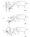
- FIG. 2 is a schematic diagram showing a specific example of the configuration of the second device.
- the introduction path 20 is bent on the upstream side of the first portion P1 so that the member M1 The interference with the introduction route 20 is avoided.
- the second device 102b shown in (b) when the inclined portion of the introduction path 20 is linear, the other member M2 exists at a position that interferes with the inclined portion. Interference between the member M2 and the inclined portion is avoided by bending the inclined portion into a curved shape.
- the second device 102c shown in (c) since the other member M3 is present on the downstream side of the first portion P1, the second device 102c is inclined to the lower side toward the drawing more greatly than in the example shown in (b). By bending the portion into a curved shape, interference between the member M3 and the inclined portion is avoided. As a result, in the second device 102c, a portion Pb lower than the first portion P1 is formed between the first portion P1 and the second portion P2 in the introduction path 20.
- the reducing agent remaining without being used for the reduction of the target substance tends to stay at the site Pb. Further, as described above, since the temperature of the exhaust gas decreases as it goes to the downstream side of the exhaust flow path, the problem due to the retention of the reducing agent as described above occurs as the position of the part Pb becomes to the downstream side of the exhaust flow path. The possibility of doing so increases. Therefore, when forming the site Pb lower than the first site P1 in the introduction path as shown in (C), it is desirable to form the site Pb on the upstream side (that is, near the first site) as much as possible.
- the temperature of the exhaust gas contacting the urea accumulated in the site Pb is further improved by forming the site Pb on the upstream side (that is, near the first site) as much as possible. It can be increased, resulting in accelerated production of NH 3 by thermal decomposition of urea.
- the second device by bending the introduction path, it is possible to avoid the interference between the introduction path and other members, and stay in the exhaust passage without being used for the reduction of the target substance.
- the reducing agent used can be reduced.
- the degree of freedom in incorporating the device of the present invention into a device or equipment equipped with an internal combustion engine to which the device of the present invention is applied is increased.
- the flow of the exhaust gas is disturbed at the bent portion, and the heating of the reducing agent due to the mixing of the exhaust gas with the reducing agent and/or the contact with the high-temperature exhaust gas is promoted.
- the route from the addition of the reducing agent into the exhaust gas to the arrival at the first purification unit Is desirable to be long.
- the device of the present invention becomes long as a whole, and it may be difficult to incorporate the device of the present invention into a device or equipment in which an internal combustion engine to which the device of the present invention is applied is mounted. ..
- the third device is the above-described second device, and is an exhaust gas purification device in which the introduction path has at least one shape selected from the group consisting of U-shape, S-shape, M-shape, and spiral shape. ..
- the words "U-shaped”, “S-shaped”, “M-shaped”, and “spiral-shaped” here do not necessarily mean that these characters or structures exactly match. It suffices that the shape substantially matches the shape expressed by these words.
- the introduction path included in the third device has a U-shape, S-shape, or M-shape
- the axis of the introduction path does not necessarily have to be included in one plane. That is, the shape of the introduction path provided in the third device may be two-dimensional, or may be three-dimensional as shown in the examples described later.
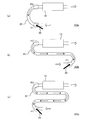
- FIG. 3 is a schematic diagram showing a specific example of the configuration of the third device.
- the third device 103a shown in (a) is provided with the introduction path 20 having a U-shape
- the third device 103b shown in (b) is provided with the introduction path 20 having an S-shape
- (c) is shown.
- the illustrated third device 103c includes an introduction path 20 having an M-shape.
- the reduction catalyst 11 included in the first purification unit 10 is omitted in FIG. 3.
- the introduction path included in the third device may have a spiral shape.
- the introduction path provided in the third device may be a combination of two or more shapes selected from the group consisting of U-shape, S-shape, M-shape and spiral shape.
- the introduction path included in the third device has at least one shape selected from the group consisting of U-shape, S-shape, M-shape, and spiral shape. Therefore, by adopting an introduction path having an appropriate shape according to the configuration of a device or equipment in which an internal combustion engine to which the third device is applied is installed, a third device having an introduction path having a desired length is provided. It can be installed in a limited space. As a result, the heating of the reducing agent due to the mixing of the exhaust gas with the reducing agent and/or the contact with the high-temperature exhaust gas can be promoted.
- the temperature of the exhaust gas decreases as it goes to the downstream side of the exhaust flow path. Therefore, when the third device has an excessively long introduction path, the first purification unit arranged on the downstream side of the introduction path. It may be difficult to sufficiently heat the reduction catalyst contained in the exhaust gas by the exhaust gas, and it may be difficult to achieve the catalytic activity required for purifying the exhaust gas. Therefore, the length of the introduction path can sufficiently achieve the catalytic activity of the reduction catalyst by the heat of the exhaust gas while promoting the heating of the reducing agent by mixing the exhaust gas with the reducing agent and/or contacting the exhaust gas with a high temperature. It is necessary to determine as appropriate.
- the first purification unit included in the device of the present invention may further include an exhaust purification unit other than the reduction catalyst (for example, an ammonia slip catalyst (ASC) or the like). Furthermore, the device of the present invention may further include a purifying unit other than the first purifying unit.
- an exhaust purification unit other than the reduction catalyst for example, an ammonia slip catalyst (ASC) or the like.
- the device of the present invention may further include a purifying unit other than the first purifying unit.
- the fourth device is the device of the present invention according to various embodiments including the above-described first device to third device, and is arranged upstream of the introduction path in the exhaust flow path to purify the exhaust gas.
- the exhaust gas purification device further includes a second purification unit.
- the second purifying unit is an exhaust purifying unit selected from a wide variety of exhaust purifying units used in the art according to the type of substance contained in the exhaust gas discharged from the internal combustion engine to which the fourth device is applied. Can be included. Specific examples of such an exhaust purification unit include, for example, a diesel oxidation catalyst (DOC: Diesel Oxidation Catalyst) and DPF.
- DOC diesel Oxidation Catalyst
- the exhaust purification units included in the second purification unit included in the fourth device may be arranged in any order as long as they are compatible with the exhaust purification function of each purification unit.
- a DOC and a DPF are provided in the second purification unit arranged on the upstream side of the introduction route and the DOC and DPF are provided on the downstream side of the introduction route, as shown in an embodiment described later.
- You may provide SCR and ASC in the 1st purification
- a plurality of exhaust gas purification units may be arranged in parallel for the purpose of, for example, reducing the pressure loss in the second purification unit.
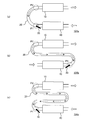
- FIG. 4 is a schematic diagram showing a specific example of the configuration of the fourth device.
- the fourth device 104a to the fourth device 104c shown in (a) to (c) of FIG. 4 correspond to the third device 103a to the third device 103c shown in (a) to (c) of FIG. 3, respectively.
- the third device 103a to the third device 103c are different from each other in that a second purifying unit 40 is further provided on the upstream side of the introduction path 20.
- the present invention device having various configurations, such as the present invention device having the introduction route and the present invention device having the introduction route having a spiral shape, as shown in FIGS. It goes without saying that the second purification section can be provided on the upstream side of the.
- the device of the present invention is installed such that the second part is higher than the first part in the operating state, and the second purification part is provided on the upstream side of the first part, which is the part lower than the second part. .. Therefore, the second purification unit is typically arranged at a position lower than the first purification unit.
- the fourth device according to the type of the substance contained in the exhaust gas discharged from the internal combustion engine to which the fourth device is applied, various exhaust purification units used in the technical field can be used. By including the exhaust purification unit selected from the inside in the second purification unit, the function as the exhaust purification device can be further enhanced.
- the activity of the catalyst largely depends on the temperature of the catalyst. Even in various exhaust gas purification catalysts such as reduction catalysts used to purify exhaust gas emitted from internal combustion engines, in order to fully exhibit exhaust gas purification performance, the temperature of each catalyst is maintained above the catalyst activation temperature. It is important to. In addition, from the viewpoint of effectively using the reducing agent for the reduction of the target substance such as the generation of NH 3 by the above-mentioned thermal decomposition of urea, it is desirable to maintain the temperature of the introduction route at a predetermined temperature or higher. ..
- the first purifying unit and the introduction route (and the second purifying unit when the present invention device includes the second purifying unit) included in the device of the present invention is heated by the exhaust gas flowing inside, the exhaust gas purifying unit included in the purifying unit.
- the catalyst constituting the unit and the introduction path are also heated by the exhaust gas.
- the fifth device is the device of the present invention according to various embodiments including the above-described first device to fourth device, and at least the introduction path and the first purification unit are supported and housed inside and exhausted. And a casing having an inlet and an outlet.
- the configuration for supporting the introduction path and the first purification section inside the casing is not particularly limited, and the introduction path and the first purification section may be fixed to the inner wall of the casing via a support member such as a stay, for example.
- the introduction path and the first purification unit may be fixed to the inner wall of the casing by the partition plate.
- the fifth device includes the second purification unit
- the second purification unit may be supported and housed inside the casing, or the second purification unit may be arranged outside the casing.
- the exhaust gas discharged from the internal combustion engine is guided to the introduction path via the inlet of the casing, and the exhaust gas discharged from the first purification unit is discharged from the casing via the outlet of the casing.
- the fifth device includes the second purifying unit and the second purifying unit is supported and housed inside the casing, the exhaust gas discharged from the internal combustion engine is guided to the second purifying unit through the inlet of the casing. Then, the exhaust gas discharged from the second purification unit is guided to the first purification unit via the introduction path, and the exhaust gas discharged from the first purification unit is discharged from the casing via the outlet of the casing. Composed.
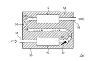
- FIG. 5 is a schematic diagram showing an example of the configuration of the fifth device.
- the fifth device 105 shown in FIG. 5 corresponds to the fourth device 104b shown in FIG. 4B, and supports and accommodates the first purification unit 10, the introduction path 20, and the second purification unit 40 inside. It differs from the fourth device 104b in that it further includes a casing 50 having an exhaust inlet 51 and an outlet 52.
- the exhaust gas discharged from the internal combustion engine (not shown) is guided to the second purification unit 40 via the inlet 51, and the exhaust gas discharged from the second purification unit 40 passes through the introduction path 20 to the first purification unit 40.
- the exhaust gas guided to the first purification unit 10 and discharged from the first purification unit 10 is configured to be discharged from the casing 50 via the outlet 52.
- the introduction path and the first purification unit are supported and housed inside the casing. Therefore, as compared with the device of the present invention that does not include such a casing, heat radiation to the surrounding environment is reduced at least in the introduction path and the first purification section. As a result, it becomes easier to maintain the temperatures of the exhaust purification unit such as the reduction catalyst and the introduction path included in the first purification unit at sufficiently high temperatures, the exhaust purification performance of the exhaust purification unit is improved, and the target substance is improved.
- the reducing agent can be used more effectively for the reduction of When the fifth device includes the second purifying unit and the second purifying unit is supported and housed inside the casing, the same effect can be achieved for the second purifying unit.
- the fifth device 105 shown in FIG. 5 is merely an example, and the casing described above is further provided in any of the devices of the present invention according to various embodiments including the first device to the fourth device described above.
- the fifth device can be configured as follows.
- the first purification unit included in the fifth device may include the DPF.
- the DPF may be removed from the exhaust purification device. It may be necessary to remove the soot accumulated inside. Therefore, when the fifth device is equipped with such a type of DPF, the DPF is operatively incorporated in a device or equipment equipped with an internal combustion engine to which the fifth device is applied. It is desirable to be able to detach.
- the fifth device further includes a diesel particulate filter supported and housed inside the casing, and the diesel particulate filter can be attached to and detached from the exhaust gas purification device in operation.
- a diesel particulate filter supported and housed inside the casing, and the diesel particulate filter can be attached to and detached from the exhaust gas purification device in operation.
- a lid or a cover that is detachably fixed to a part of the outer wall of the casing so that the DPF supported and housed inside the casing can be taken out or the DPF can be installed inside the casing. May be provided.
- At least the introduction route and the first purification unit are supported and housed inside the casing, so that at least the introduction route and the first purification unit reduce heat radiation to the ambient environment and reduce exhaust gas. It is possible to effectively utilize the heat received. However, from the viewpoint of more effectively utilizing the heat received from the exhaust gas, it is desirable to reduce the heat radiation to the surrounding environment via the casing.
- the sixth device is the above-described fifth device and is an exhaust gas purification device in which at least a part of the space between the introduction path and the first purification unit and the casing is filled with a heat insulating material.
- the heat insulating material is not particularly limited as long as it at least prevents heat conduction between the introduction path and the first purifying section and the casing and can withstand the use environment and use conditions (for example, temperature and vibration) of the sixth device. Not done.
- Specific examples of the heat insulating material include glass wool and the like.
- at least the entire area of the introduction path and the space between the first purification unit and the casing may be filled with the heat insulating material.
- a part of the space may have a region not filled with a heat insulating material.
- the sixth device includes the second purifying unit and the second purifying unit is supported and housed inside the casing
- at least the second purifying unit, the introduction path, and the first purifying unit and the casing are provided. It is desirable that at least a part of the space be filled with a heat insulating material.
- the heat insulating material is filled in all the regions of the space between the casing and all the components housed inside the casing. Is desirable.
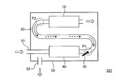
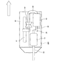
- FIG. 6 is a schematic diagram showing an example of the configuration of the sixth device.
- the sixth device 106 shown in FIG. 6 corresponds to the fifth device 105 shown in FIG. 5, and the heat insulating material 53 is provided in the space between the first purifying unit 10, the introduction route 20, and the second purifying unit 40 and the casing 50. Is different from the fifth device 105 in that it is filled.
- the sixth device at least a part of the introduction path and the space between the first purification unit and the casing is filled with the heat insulating material. Therefore, compared to the fifth device in which the space is not filled with the heat insulating material, the heat retaining effect by the casing is higher, and the heat radiation to the surrounding environment via the casing is further reduced. As a result, it becomes easier to maintain the temperature of the exhaust purification unit such as the reduction catalyst and the introduction path included in the first purification unit at a sufficiently high temperature, and the exhaust purification performance of the exhaust purification unit is more reliably improved.
- the reducing agent can be used more effectively for the reduction of the target substance.
- the sixth device includes the second purifying unit and the second purifying unit is supported and housed inside the casing, the same effect can be achieved for the second purifying unit.
- the casing and the combination of the casing and the heat insulating material reduce the heat radiation to the surrounding environment, and the exhaust purification unit and the introduction path included in these exhaust purification devices are kept warm. ..
- the heat (exhaust heat) of the exhaust exhausted from (the first purification unit included in) these exhaust purification devices it is possible to use the heat (exhaust heat) of the exhaust exhausted from (the first purification unit included in) these exhaust purification devices. desirable.
- the seventh device is the above-described fifth device or sixth device, and the exhaust gas discharged from the first purification unit flows into at least a part of the space between the introduction path and the first purification unit and the casing.
- the exhaust gas purifying device is configured to be discharged from the casing via the outlet of the casing after being discharged.
- the seventh device includes the second purifying unit and the second purifying unit is supported and housed inside the casing, at least the space between the second purifying unit, the introduction path, and the first purifying unit and the casing. It is desirable that the exhaust gas discharged from the first purification unit flows partly.
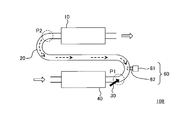
- FIG. 7 is a schematic diagram showing an example of the configuration of the seventh device.
- the seventh device 107 shown in FIG. 7 corresponds to the fifth device 105 shown in FIG. 5, and the exhaust gas discharged from the first purification unit is the first purification unit 10, the introduction route 20, and the second purification unit 40.
- the fifth device 105 is different from the fifth device 105 in that it is configured to be discharged to the space between the casing 50 and the exhaust, and after being discharged to the space, to be discharged from the outlet 52.
- the labyrinth structure is provided in the space, so that the first purifying unit is provided.
- the exhaust gas discharged from 10 may flow uniformly over the entire space without being biased to a specific region.
- the inside of the casing 50 is divided into a plurality of regions by a partition plate as shown in an embodiment described later, through holes are formed in the partition plate, and exhaust gas can flow to these plurality of regions. You may do it.
- the exhaust gas discharged from the first purification unit 10 is allowed to flow in the space between the first purification unit 10, the introduction path 20, and the second purification unit 40 and the casing 50.
- the region may be filled with the heat insulating material as described in the description of the sixth device. That is, in the space between the first purifying unit 10, the introduction path 20, the second purifying unit 40, and the casing 50, a region in which exhaust gas discharged from the first purifying unit 10 flows and a region filled with a heat insulating material. And may coexist.
- the exhaust gas discharged from the first purification unit flows from the casing through the outlet of the casing after the exhaust gas flows into at least a part of the space between the introduction route and the first purification unit and the casing. It is configured to be discharged.
- the exhaust gas discharged from the first purification unit is introduced into the seventh device, passes through at least the introduction path and the first purification unit, and is then discharged from the first purification unit. Therefore, the temperature of the exhaust gas discharged from the first purification unit is lower than the temperature of the exhaust gas discharged from the internal combustion engine and flowing into the seventh device. However, the temperature of the exhaust gas discharged from the first purification unit is higher than the temperature of the environment surrounding the seventh device (for example, the atmosphere).
- the heat insulating effect by the casing is higher than that of the fifth device in which the exhaust gas does not flow in the space. Can be further increased to further reduce heat radiation to the surrounding environment via the casing.
- heat dissipation to the surrounding environment is reduced by the combination of the casing and the casing and the heat insulating material, respectively, and the exhaust purification unit and the introduction path provided in these exhaust purification devices are kept warm. .. Further, in the above-described seventh device, by causing the exhaust gas discharged from the first purification unit to flow in the space between the component member housed in the casing and the casing, heat dissipation to the surrounding environment is further reduced, and The exhaust purification unit and the introduction path provided in the exhaust purification device are more reliably kept warm.
- the temperature of the exhaust gas flowing through the device of the present invention may be positively raised to maintain the temperature of the exhaust gas purification unit and the introduction path provided in the device of the present invention at a higher temperature.
- the eighth device is a device of the present invention according to various embodiments including the first device to the seventh device described above, and communicates with a combustion chamber that generates combustion gas by combustion of fuel and a combustion chamber.
- the exhaust gas purification device further includes a combustor having a combustion gas supply unit that supplies combustion gas to the upstream side of the first purification unit in the exhaust flow path.
- the location of the combustion gas supply unit is not particularly limited as long as it is on the upstream side of the first purification unit, and may be the introduction path on the upstream side of the first site, or on the downstream side of the first site. May be introduced.
- the combustion gas supply unit may be arranged in the exhaust passage upstream of the second purification unit.
- the combustion gas supply unit may be arranged in the exhaust flow passage upstream of the casing.
- a combustion gas supply unit is disposed near the downstream side of the first portion in the introduction path to promote heating of the reducing agent by contact with high-temperature combustion gas to generate, for example, NH 3 by thermal decomposition of urea. May be promoted.
- the configuration of the combustor is not particularly limited as long as the combustion gas generated by the combustion of the fuel can be supplied to the exhaust passage upstream of the first purification unit.
- a combustor is configured to supply fuel and air to a combustion chamber by a fuel supply device and an air supply device, ignite the fuel by an ignition device (for example, a glow plug, etc.), and burn the fuel in the combustion chamber. To be done.
- the high-temperature combustion gas generated by the combustion of the fuel is guided from the combustion chamber to the combustion gas supply unit by, for example, the pressure of air supply by the air supply device and the pressure resulting from the volume expansion accompanying the combustion, It is supplied upstream of the first purification unit in the exhaust passage.
- the materials forming the combustor components and the structures of these components should be appropriately selected and designed in consideration of the temperature, pressure, vibration, etc. assumed in the operating environment and operating conditions of the eighth device. You can However, since details of the combustor are well known to those skilled in the art, further description is omitted (for example, refer to Patent Document 2).
- FIG. 8 is a schematic diagram showing an example of the configuration of the eighth device.
- the eighth device 108 shown in FIG. 8 corresponds to the fourth device 104b shown in FIG. 4(b), and is in communication with the combustion chamber 61 and the combustion chamber 61 for generating combustion gas by combustion of the fuel and the exhaust flow path.
- the fourth device 104b differs from the fourth device 104b in further including a combustor 60 having a combustion gas supply unit 62 that supplies combustion gas to the upstream side of the first purification unit 10 in.
- the combustion gas supply unit 62 is arranged near the downstream side of the first portion P1 in the introduction path 20.
- the eighth device the high temperature combustion gas is supplied to the upstream side of the first purification unit in the exhaust passage. Therefore, the temperature of the exhaust gas flowing through the eighth device is positively increased, and the temperatures of the exhaust purification unit such as the reduction catalyst and the introduction path included in the first purification unit included in the eighth device are easily increased to a higher temperature. be able to. As a result, the exhaust purification performance of the exhaust purification unit can be further enhanced and the reducing agent can be used more effectively for the reduction of the target substance, as compared with the device of the present invention that does not include a combustor.
- the combustion gas supply unit may be provided in the middle of the introduction path (may be upstream or downstream of the first portion), upstream of the casing, or upstream of the second purification unit. It may be provided. Therefore, when the eighth device includes the second purification unit and the high temperature combustion gas is supplied to the upstream side of the second purification unit in the exhaust passage by the combustion gas supply unit, the exhaust gas included in the second purification unit. Also in the purification unit, the exhaust purification performance can be further enhanced in the same manner as above.
- the eighth device 108 shown in FIG. 8 is merely an example, and the combustor described above is further provided in any of the devices of the present invention according to various embodiments including the first device to the seventh device described above. Thus, the eighth device can be configured.
- an exhaust emission control device according to a ninth embodiment of the present invention (hereinafter, may be referred to as a “ninth device”) will be described with reference to the drawings.
- the temperature of the exhaust gas flowing into the exhaust flow passage is positively increased by the combustor that supplies the high temperature combustion gas to the upstream side of the first purification unit in the exhaust flow passage, and the reduction catalyst
- the temperature of the exhaust purification unit and the introduction path is maintained at a higher temperature. If the heat generated by the combustion of the fuel in the combustion chamber can be efficiently transmitted to the exhaust gas, the efficiency of heating the exhaust gas by such a combustor can be further increased.
- the ninth device is the above-described eighth device, and further includes a heat dissipation member that is in contact with the exhaust gas on the upstream side of the first purification unit in the exhaust flow path and that is capable of conducting heat with the combustion gas supply unit. It is an exhaust emission control device provided.
- the location of the heat dissipation member is not particularly limited as long as it is on the upstream side of the first purification section, and may be an introduction path on the upstream side of the first portion, or an introduction path on the downstream side of the first portion. It may be a route.
- the heat dissipation member may be arranged in the exhaust passage upstream of the second purification unit.
- a heat dissipation member may be arranged in the exhaust flow passage upstream of the casing. From the viewpoint of efficiently transmitting the heat generated by the combustion of the fuel in the combustion chamber to the exhaust gas, it is desirable to dispose the heat dissipation member so as to be close to the combustion gas supply unit.
- the structure of the heat dissipation member is not particularly limited as long as it can transfer the heat generated by the combustion of the fuel in the combustion chamber to the exhaust gas.
- the heat dissipation member may be a part (for example, a tip) of the combustion gas supply unit exposed or protruding in the exhaust passage, or a heat dissipation plate disposed so as to be capable of conducting heat with the combustion gas supply unit. It may be a separate member such as.
- the material forming the heat dissipation member, the structure of the heat dissipation member, and the like can be appropriately selected and designed in consideration of the temperature, load, vibration, and the like assumed in the use environment and use conditions of the ninth device. From the viewpoint of efficiently transmitting the heat generated by the combustion of the fuel in the combustion chamber to the exhaust gas, it is desirable that the heat dissipation member be formed of a material having a high thermal conductivity (for example, metal).
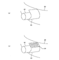
- FIG. 9 is a schematic diagram showing a specific example of the configuration of the heat dissipation member included in the ninth device.
- a bent plate-shaped heat dissipation member 63 is arranged at the tip of the combustion gas supply unit 62 protruding inside the introduction path 20.
- the heat generated by the combustion of the fuel in the combustion chamber (not shown) is transmitted to the heat radiation member 63 via the combustion gas supply unit 62, and is transmitted to the exhaust gas flowing inside the introduction path 20 via the heat radiation member 63.
- the ninth device further includes the heat radiating member that is in contact with the exhaust gas on the upstream side of the first purification unit in the exhaust flow path and is configured to be able to conduct heat with the combustion gas supply unit.
- the heat generated by the combustion of the fuel in the combustion chamber of the combustor can be efficiently transmitted to the exhaust gas. Therefore, it is possible to more efficiently raise the temperature of the exhaust gas flowing to the ninth device and maintain the temperatures of the exhaust purification unit such as the reduction catalyst and the introduction path included in the first purification unit included in the ninth device at a higher temperature. You can As a result, the exhaust purification performance of the exhaust purification unit can be further enhanced, and the reducing agent can be used more effectively for the reduction of the target substance.
- ⁇ Modification> it is not desirable to cause an excessive pressure loss in the exhaust gas flowing through the exhaust passage from the viewpoint of maintaining the output performance of the internal combustion engine. Therefore, it is desirable that one or more through holes be formed in the heat dissipation member. As a result, it is possible to reduce an increase in pressure loss due to the heat dissipation member.
- a heat dissipation member include a punching plate and a mesh plate.
- the heat dissipation member 63 is a punching plate and a plurality of through holes 64 are formed.
- one or more through-holes, protrusions and/or fins may be formed in the heat dissipation member as long as an excessive pressure loss is not generated in the exhaust gas flowing inside the exhaust passage. That is, the heat dissipation member may function as a mixer. As a result, the effect of increasing the contact area between the heat dissipation member and the exhaust gas and promoting the mixing of the exhaust gas and the reducing agent on the downstream side of the heat dissipation member (by causing turbulent flow or swirl flow in the exhaust gas flow) are achieved To be done.
- the reducing agent collides with the heat dissipation member to disperse the reducing agent in the exhaust gas, or the reducing agent is spread on the surface of the heat dissipation member.
- heating of the reducing agent may be promoted by contacting the exhaust gas flowing through the introduction path and the heat radiation member. According to this, for example, the generation of NH 3 by the thermal decomposition of urea is promoted. That is, the heat dissipation member may function as a reactor.
- a so-called “mixing member” is provided in the exhaust passage for the purpose of, for example, promoting the mixing of the exhaust gas and the reducing agent in the exhaust passage, and a turbulent flow or a swirling flow is added to the exhaust flow. It is known to cause (swirl) (see, for example, Patent Document 3).
- the tenth device is a device of the present invention according to various embodiments including the above-described first device to ninth device, and is provided in the exhaust flow on the upstream side of the first purification unit in the exhaust flow path.
- the exhaust gas purification device further includes a mixing member configured to generate a turbulent flow or a swirling flow.
- the location where the mixing member is provided is not particularly limited as long as it is on the upstream side of the first purification section, and may be an introduction path on the upstream side of the first portion, or an introduction path on the downstream side of the first portion. It may be a route.
- the mixing member may be arranged in the exhaust passage upstream of the second purification unit.
- a mixing member may be arranged in the exhaust flow passage upstream of the casing.
- the material forming the mixing member, the structure of the mixing member, and the like can be appropriately selected and designed in consideration of the temperature, load, vibration, and the like assumed in the usage environment and usage conditions of the tenth device.
- Specific examples of the mixing member include, for example, a baffle plate, a protrusion, and a fin that protrudes inward from a member that defines the exhaust passage, and one or more through holes, protrusions, and/or fins that are interposed in the exhaust passage. Examples thereof include a plate-shaped member formed with. Since the details of the mixing member are well known to those skilled in the art, further description will be omitted (for example, refer to Patent Document 3).
- FIG. 10 is a schematic diagram showing a specific example of the configuration of the mixing member included in the tenth device.
- a plurality of fins 72 and through holes 73 are formed by bending a notch formed in a disk-shaped plate 71 as a substrate.
- 10A is a perspective view showing the entire contents of the mixing member 70
- FIG. 10B is a front view when the mixing member 70 is observed from the protruding side of the fin 72
- FIG. 10C is a view of the mixing member 70. It is a side view.
- the mixing member 70 shown in FIG. 10 is arranged in the exhaust flow path so that the flow of the exhaust gas is blocked by the plate 71, and the exhaust gas passing through the through holes 73 is deflected by the fins 72 bent in alternate directions. It causes turbulence. Thereby, for example, an effect such as promotion of mixing of the exhaust gas and the reducing agent on the downstream side of the mixing member 70 can be achieved.
- the mixing member 70 is configured as a so-called "swirler" by configuring the fins 72 so that the exhaust gas passing through each through hole 73 produces a swirling flow in the same direction around the axis of the exhaust flow path. You can also
- the tenth device further includes the mixing member configured to generate the turbulent flow or the swirl flow in the flow of the exhaust gas on the upstream side of the first purification unit in the exhaust flow path, and thus, for example, the mixing member. It is possible to achieve effects such as promotion of mixing of the exhaust gas and the reducing agent on the downstream side of the.
- the mixing member by disposing the mixing member on the downstream side of the first portion in the introduction path, the reducing agent collides with the mixing member to disperse the reducing agent in the exhaust gas, or the reducing agent is spread on the surface of the mixing member.
- heating of the reducing agent may be promoted by contact with exhaust gas flowing in the introduction path and the mixing member. According to this, for example, the generation of NH 3 by the thermal decomposition of urea is promoted. That is, the mixing member may function as a reactor.
- the mixing member be formed of a material having a high thermal conductivity (for example, metal).
- the mixing member may be configured to be capable of conducting heat to the combustion gas supply unit, and the mixing member may be used as the heat dissipation member described above.
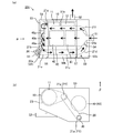
- FIG. 11 is a schematic diagram showing an example of the configuration of an exhaust emission control device according to the first embodiment of the present invention (hereinafter sometimes referred to as “first embodiment device”).
- FIG. 3A is a schematic top view (plan view) of the device of the first embodiment in an operating state (specifically, a state of being mounted on a vehicle).
- (B) is a view of the first embodiment apparatus in the operating state as viewed from the side direction ( ⁇ ), and the upper side ( ⁇ ) of the drawing is the upper side (upward direction) in the operating state (vehicle mounted state).
- the second purifying unit 40 is drawn so as to be shifted near the center of the casing 50 for the purpose of making it easier to see the arrangement of the introduction path and the flow of exhaust gas, so that (a) and (b) are shown.
- the arrangement of the second purification unit 40 is different between.
- the first embodiment device 201 will be described with reference to FIG. 11.
- An inlet 51 and an outlet 52 are provided on the side wall of a box-shaped casing 50 made of stainless steel.
- a tubular member that communicates the inside and outside of the casing 50 with each of the inlet 51 and the outlet 52 is airtightly fixed by welding around the entire circumference.
- the tubular members fixed to the inlet 51 and the outlet 52 may be referred to as the inlet pipe 51 and the outlet pipe 52, respectively.
- a urea water injection device hereinafter sometimes abbreviated as “injection device 30” as the reducing agent addition unit 30 is inserted into a wall defining the casing 50, and airtightly fixed by a screwing means (not shown). Has been done.
- the inside of the casing 50 is airtightly divided into three regions by the first partition plate 56 and the second partition plate 57, and the first chamber 50a, the second chamber 50b, and the third chamber 50c are sequentially arranged from the left side of FIG. Are formed respectively.
- the inlet pipe 51 is connected to one end of the cylindrical second purification unit 40 via a cone portion (also referred to as a “tapered portion”) 54.
- the other end of the second purification unit 40 is fixed and closed while being in contact with the casing 50, and exhaust gas is discharged from the inside of the second purification unit 40 to a portion located inside the first chamber 50a.
- a plurality of discharge holes 40a are formed on the peripheral wall.
- DOC diesel oxidation catalyst
- DPF diesel particulate filter
- the exhaust gas that has flowed into the inlet pipe 51 passes through the cone portion 54, as shown by the solid arrow, and then flows out from the exhaust hole 40a after being oxidized by the DOC 41 and filtered by the DPF 42. Diffuses into the chamber 50a. Then, the exhaust gas that has diffused into the inside of the first chamber 50a flows into the inside of the communication pipe 21 through the communication hole 21b formed in the peripheral wall of the inlet portion 21a of the communication pipe 21. That is, in the apparatus 201 of the first embodiment, the first chamber 50a injects exhaust gas from the second purifying section 40 to the communication pipe 21 while inverting the flow of exhaust gas, except for the region occupied by the second reversing chamber 23 described later.
- the communication pipe 21 includes a first straight pipe portion 21c having an inlet portion 21a and a communication hole 21b, a first bent portion 21d, an intermediate straight pipe portion 21e, a second bent portion 21f, and a second straight pipe portion 21h having an outlet portion 21g. Are integrally formed in this order.
- the substantially U-shaped communication pipe 21 is inclined so that the outlet portion 21g is higher than the inlet portion 21a. It is located in.
- one communication pipe 21 is formed by connecting the respective parts formed as separate members as described above.
- one pipe is formed in a substantially U shape.
- the communication pipe 21 may be formed by bending the connecting pipe 21.
- the end portion of the communication pipe 21 on the inlet portion 21a side is fixed and closed while being in contact with the inner surface of the mounting wall portion 55 that is a part of the wall of the casing 50. Then, the tip of the injection device 30 fixed so as to be inserted into the mounting wall portion 55 is coaxially positioned inside the inlet portion 21a. As a result, the reducing agent injected (added) by the injection device 30 such as urea water is released into the communication pipe 21, and is mixed with the exhaust gas flowing from the communication hole 21b to be vaporized and diffused.
- the reducing agent injected (added) by the injection device 30 such as urea water
- the vaporized reducing agent receives the heat of the exhaust gas in the process of flowing inside the communication pipe 21 downstream, and is converted (converted) into ammonia (NH 3 ) by a thermal decomposition reaction.
- a sufficiently long reaction time can be secured for the thermal decomposition due to the long flow path inside the substantially U-shaped communication pipe 21.
- the NH 3 thus generated is discharged into the inside of the second inversion chamber 23 from the outlet 21g together with the exhaust.
- the second reversing chamber 23 having a substantially triangular cross section is a volume having a thin depth (thickness) and is arranged in the first chamber 50a.
- an outlet portion 21g that is a downstream end portion of the communication pipe 21 and an upstream end portion of the first purification unit 10 are fitted and fixed, respectively.
- the exhaust gas discharged from the outlet portion 21g is inverted and diffused inside the second inversion chamber 23, and evenly flows into the first purification unit 10.
- the second reversal chamber 23 also functions as a chamber.
- the flow of exhaust gas up to this point is indicated by a thick solid arrow in FIG.
- the communication pipe 21, the first reversal chamber 22 and the second reversal chamber 23 constitute the introduction path 20 included in the device of the present invention.
- the inlet portion 21a of the communication pipe 21 where the urea water as the reducing agent is injected by the injection device 30 corresponds to the first portion P1 of the device of the present invention, and is arranged at a position higher than the inlet portion 21a of the communication pipe 21.
- the outlet portion 21g that is formed corresponds to the second portion P2 in the device of the present invention.
- Nitrogen oxides (NOx) contained in the exhaust gas that has flowed into the first purification unit 10 together with NH 3 are reduced to nitrogen (N 2 ) by the selective catalytic reduction NOx removal device (SCR) 11, and then excess NH 3 is added. Is oxidized to N 2 and water (H 2 O) by the ammonia slip catalyst (ASC) 12.
- the exhaust gas that has undergone various purification processes in this manner is discharged from the first purification unit 10 into the second chamber 50b.
- a large through hole (large opening) (not shown) is bored in the second partition plate 57 so that exhaust gas can freely flow between the second chamber 50b and the third chamber 50c. ..
- the communication pipe 21 (specifically, the first bent portion 21d, the intermediate straight pipe portion 21e, and the second bent portion 21f) and the outer surface of the cone portion 54 are heated by high-temperature exhaust gas. The effect of heating by such exhaust will be described later with reference to the schematic diagram shown in FIG.
- a part of the exhaust gas discharged from the first purification unit 10 is diffused into the second chamber 50b without passing through the large opening of the second partition plate 57.
- the exhaust gas circulated in the third chamber 50c again passes through the large opening of the second partition plate 57 and returns to the second chamber 50b. Then, the exhaust gas that circulates inside the second chamber 50b eventually passes through the outlet pipe 52 and is discharged to the outside of the casing 50. At this time, the first straight pipe portion 21c, the second straight pipe portion 21h, and the second purifying portion 40 are also respectively heated from the outer surface by the exhaust gas circulating inside the second chamber 50b.
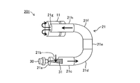
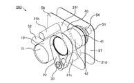
- FIG. 12 is a perspective view schematically showing a three-dimensional layout of the injection device 30, the communicating pipe 21, and the selective catalytic reduction NOx removal device (SCR) 11 which are the main parts of the device 201 of the first embodiment.
- the upper side is the upper side in the operating state (upward).
- the spray 31 of the reducing agent injected (added) from the injection device 30 is discharged into the inside of the communication pipe 21, is mixed with the exhaust gas flowing from the communication hole 21b, is vaporized and diffused, and is connected to the communication pipe 21. It is converted to NH 3 by thermal decomposition in the process of flowing to the downstream in the inside of.
- the reducing agent that adheres to the inner wall of the communication pipe 21 without being vaporized/diffused hereinafter sometimes referred to as “residual reducing agent”.
- residual reducing agent is likely to adhere to the inner wall surfaces of the first bent portion 21d to the second bent portion 21f.
- the first bending portion 21d to the second bending portion 21f are inclined so that the second bending portion 21f side is higher than the first bending portion 21d side. Therefore, the reducing agent attached to the inner wall surfaces of the first bent portion 21d to the second bent portion 21f moves downward (to the first straight pipe portion 21c side) by the action of gravity. That is, the residual reducing agent flows backward from the downstream side to the upstream side.
- the exhaust gas discharged from the internal combustion engine (not shown) always flows from the upstream side to the downstream side. It is pushed up (pushed back).
- the contact time between the residual reducing agent and the exhaust gas increases, so that vaporization of the residual reducing agent and conversion to NH 3 are promoted.
- the precipitation of the residual reducing agent inside the communication pipe 21 is reduced, the conversion of the reducing agent to NH 3 is promoted, and the NOx in the selective catalytic reduction NOx removal device (SCR) 11 is increased. The reduction process of is promoted.
- the high-temperature exhaust gas discharged from the first purification unit 10 as described above flows through the second chamber 50b and the third chamber 50c of the casing 50 and then is discharged from the outlet pipe 52.
- the communication pipe 21 (specifically, the first straight pipe portion 21c, the first bent portion 21d, the intermediate straight pipe portion 21e, the second bent portion 21f, and the second straight pipe portion 21h), the second purification portion.
- the outer surfaces of 40 and the cone portion 54 are heated by the hot exhaust gas. Such heating by exhaust also promotes vaporization, diffusion or thermal decomposition of the residual reducing agent.
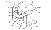
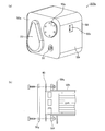
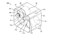
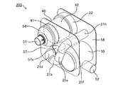
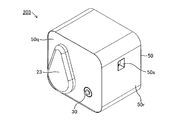
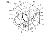
- FIG. 13 to FIG. 19 are schematic diagrams showing an example of the configuration of an exhaust emission control device according to the second embodiment of the present invention (hereinafter sometimes referred to as “second embodiment device”).
- FIG. 13 is a schematic front view of the second example device 202 when the second example device 202 from which the first end plate 50p, which is the outer wall on the inlet 51 side of the casing 50, is removed is observed from the inlet 51 side. is there.
- FIG. 14 is a schematic perspective view showing the outer appearance of the second embodiment device 202 when the second embodiment device 202 is observed from the inlet 51 side of the casing 50.
- FIG. 13 is a schematic front view of the second example device 202 when the second example device 202 from which the first end plate 50p, which is the outer wall on the inlet 51 side of the casing 50, is removed is observed from the inlet 51 side. is there.
- FIG. 14 is a schematic perspective view showing the outer appearance of the second embodiment device 202 when the second embodiment device 202 is observed from the inlet
- FIG. 15 is a schematic perspective view of the second embodiment device 202 in which only the first end plate 50p of the casing 50 is removed from the second embodiment device 202 shown in FIG.
- the first partition plate 56 that divides the internal space of the casing 50 is omitted, and the portion accommodated inside the casing 50 is indicated by a broken line.
- FIG. 16 shows a second embodiment in which the substantially rectangular tubular side wall 50r of the casing 50 and the second end plate 50q, which is the outer wall on the side opposite to the inlet 51, are further removed from the second embodiment device 202 shown in FIG. 3 is a schematic perspective view of an example device 202.
- the first partition plate 56 that partitions the internal space of the casing 50 is not omitted, and the portion hidden behind the second partition plate 57 is represented by a broken line.
- FIG. 17 is a schematic perspective view showing the external appearance of the second embodiment device 202 when the second embodiment device 202 is observed from the side opposite to the inlet 51 of the casing.
- FIG. 18 is a schematic perspective view of the second embodiment device 202 in which only the second end plate 50q, which is the outer wall on the opposite side of the inlet 51 of the casing 50, is removed from the second embodiment device 202 shown in FIG. Is. However, in FIG. 18, the first partition plate 56 and the second partition plate 57 that partition the internal space of the casing 50 are omitted, and the portion housed inside the casing 50 is indicated by a broken line.
- FIG. 18 is a schematic perspective view showing the external appearance of the second embodiment device 202 when the second embodiment device 202 is observed from the side opposite to the inlet 51 of the casing.
- FIG. 18 is a schematic perspective view of the second embodiment device 202 in which only the second end plate 50q, which is the outer wall on the opposite side of the inlet 51 of the casing 50, is removed from
- FIG. 19 shows a second embodiment device 202 in which the substantially rectangular side wall 50r of the casing 50 and the first end plate 50p which is the outer wall on the inlet 51 side are further removed from the second embodiment device 202 shown in FIG. 3 is a schematic perspective view of FIG.
- the first partition plate 56 and the second partition plate 57 that delimit the internal space of the casing 50 are not omitted, and the portion hidden behind the first partition plate 56 and the second partition plate 57 is a broken line. Represented by.
- the casing 50 has a structure in which the openings at both ends of the substantially rectangular tubular side wall 50r are closed by the first end plate 50p and the second end plate 50q.
- the method for closing and fixing the openings at both ends of the side wall 50r by the first end plate 50p and the second end plate 50q is the use environment and use conditions of the second embodiment device 202 (for example, temperature, pressure, vibration, etc.). It is not particularly limited as long as it can withstand. Specific examples of such a method include welding, caulking, and screwing with unillustrated bolts and nuts.
- the second embodiment apparatus 202 is also provided with the second purification section 40, the introduction path 20, and the first purification section 10 in this order from the upstream side, and these are inside the casing 50. It is supported and housed in. Further, the inner space of the casing 50 is formed by the first partition plate 56 and the second partition plate 57 in order from the second end plate 50q, which is the outer wall on the side opposite to the inlet 51 side of the casing 50, in the order of the first chamber and the second chamber. , Is divided into a third chamber.
- the exhaust gas discharged from the first purification unit 10 flows from the second chamber and the third chamber, which are communicated with each other through the large opening 57a formed in the second partition plate 57, and then from the outlet 52 of the casing 50. It is discharged to the outside.
- the substantially U-shaped communicating pipe is inclined so that the outlet portion 21g is higher than the inlet portion 21a. It is arranged.
- the communication pipe included in the device 202 of the second embodiment does not include the communication hole 21b formed in the peripheral wall of the inlet portion 21a, but includes the first straight pipe portion 21c having the inlet portion 21a, the first bent portion 21d, and the intermediate portion.
- the straight pipe portion 21e, the second bent portion 21f, and the second straight pipe portion 21h having the outlet portion 21g are integrally configured in this order.
- the first chamber 50a excluding the region occupied by the second reversing chamber 23 exhausts the second purifying unit 40 to the communication pipe while reversing the flow of the exhaust gas. Functioning as the first reversing chamber 22 for guiding.
- the first reversal chamber 22 that guides the exhaust gas from the second purification unit 40 to the inlet 21a of the communication pipe is separately formed inside the first chamber.
- the second reversing chamber 23 that guides the exhaust gas from the outlet 21g of the communication pipe to the first purifying unit 10 is formed inside the first chamber 50a. It had been.
- the second reversal chamber 23 is formed so as to bulge outside the second end plate 50q, which is the outer wall of the casing 50 on the side opposite to the inlet 51.
- the device 202 of the second embodiment basically has the same configuration as the device 201 of the first embodiment. Therefore, the device 202 of the second embodiment can also achieve the same effect as the device 201 of the first embodiment. Specifically, since the contact time between the residual reducing agent and the exhaust gas is increased by repeating the reverse flow and the forward flow of the residual reducing agent as described in the apparatus 201 of the first embodiment, the residual reducing agent is vaporized and NH 3 is discharged. Conversion is promoted. As a result, the precipitation of the residual reducing agent inside the communication pipe is reduced, the conversion of the reducing agent to NH 3 is promoted, and the NOx reduction treatment in the SCR 11 is promoted.
- the high temperature exhaust gas discharged from the first purification unit 10 flows through the second chamber and the third chamber of the casing 50 and then is discharged from the outlet pipe 52, the communication is established.
- the portion of the pipe that passes through the second chamber and the third chamber, the outer surfaces of the second purifying unit 40 and the cone unit 54 are heated by the high temperature exhaust gas.
- Such heating by exhaust also promotes vaporization, diffusion or thermal decomposition of the residual reducing agent.
- the second embodiment device is operably incorporated into a device or equipment equipped with an internal combustion engine to which the second embodiment device is applied. It is desirable to be able to attach and detach the DPF in the state where it remains.
- FIG. 20 is a schematic diagram showing an example of the configuration of a second example device 202a according to such a modification.
- (A) is a typical perspective view showing an appearance when the 2nd example device 202a is observed from the side opposite to the entrance 51.
- a cover 50g is provided in a region of the second end plate 50q, which is an outer wall on the side opposite to the inlet 51 of the casing 50, facing a second purification unit (not shown).
- the entire second purifying unit 40 (as a DPF case) is configured to be removable.
- the casing 50 includes a holding case 50h for holding the second purifying unit 40, and an end of the holding case 50h on the opposite side of the inlet 51 projects from the second end plate 50q to the outside.
- a flange 50f is formed on the peripheral portion thereof. Further, a flange is also formed at the end of the second purification section 40 (as a DPF case) on the opposite side of the inlet 51.
- the DPF can be tightened. It is possible to firmly and airtightly incorporate the second purifying unit 40 including the second purifying unit 40 into the second embodiment device 202a. On the other hand, when removing the DPF from the second embodiment device 202a for cleaning, the second purifying unit 40 can be taken out from the second embodiment device 202a in the reverse order of the above procedure.
- the device or equipment and/or The introduction path may be bent for the purpose of avoiding interference with other members constituting the device of the present invention and the introduction path.
- the exhaust gas purification device according to the third embodiment of the present invention (hereinafter sometimes referred to as the “third embodiment device”) has a bent portion more than the second embodiment device described above. It is an exhaust emission control device having an introduction path containing a large amount of
- FIG. 21 to 27 are schematic diagrams showing an example of the configuration of the third embodiment device.
- FIG. 21 is a schematic front view of the third embodiment device 203 when the third embodiment device 203 from which the first end plate 50p, which is the outer wall on the inlet 51 side of the casing 50, is removed is observed from the entrance 51 side. is there.
- FIG. 22 is a schematic perspective view showing an appearance of the third embodiment device 203 when the third embodiment device 203 is observed from the inlet 51 side of the casing 50.
- FIG. 23 is a schematic perspective view of the third embodiment device 203 in which only the first end plate 50p of the casing 50 is removed from the third embodiment device 203 shown in FIG. However, in FIG.
- FIG. 24 is a third embodiment in which the substantially rectangular tubular side wall 50r of the casing 50 and the second end plate 50q, which is the outer wall on the side opposite to the inlet 51, are further removed from the device 203 of the third embodiment shown in FIG. 3 is a schematic perspective view of an example device 203.
- the first partition plate 56 that partitions the internal space of the casing 50 is not omitted, and the portion hidden behind the second partition plate 57 is represented by a broken line.
- FIG. 25 is a schematic perspective view showing an external appearance of the third embodiment device 203 when the third embodiment device 203 is observed from the side opposite to the inlet 51 of the casing.
- FIG. 26 is a schematic perspective view of the third embodiment device 203 in which only the second end plate 50q, which is the outer wall on the opposite side of the inlet 51 of the casing 50, is removed from the third embodiment device 203 shown in FIG. Is.
- the first partition plate 56 and the second partition plate 57 that delimit the internal space of the casing 50 are omitted, and the portion housed inside the casing 50 is represented by a broken line.
- FIG. 27 is a third embodiment device 203 in which the substantially rectangular side wall 50r of the casing 50 and the first end plate 50p which is the outer wall on the inlet 51 side are further removed from the third embodiment device 203 shown in FIG. 3 is a schematic perspective view of FIG.
- the first partition plate 56 and the second partition plate 57 that delimit the internal space of the casing 50 are not omitted, and the portion hidden behind the first partition plate 56 and the second partition plate 57 is a broken line. Represented by.
- the device 203 of the third embodiment has basically the same configuration as the device 202 of the second embodiment described above.
- the third bent part 21k which is a further bent part is interposed between the first bent part 21d and the intermediate straight pipe part 21e. It differs from the device 202 of the second embodiment.
- the upward slope of the communicating pipe from the first straight pipe portion 21c to the second straight pipe portion 21h is linear.
- the upward sloped portion from the first straight pipe portion 21c of the communication pipe to the second straight pipe portion 21h is lowered. It has a convex curved shape.
- the vehicle and/or the third embodiment device 203 can be replaced by the configuration of the vehicle equipped with the internal combustion engine to which the third embodiment device 203 is applied and/or the configuration of the third embodiment device 203. It is possible to avoid the interference between the other member and the introduction route.
- the portion where the reducing agent is injected by the injection device 30 in the introduction path 20 (first portion P1) and the downstream side of the first portion P1 due to the interposition of the third bent portion 21k.
- a portion (Pb) lower than the first portion P1 is formed between the portion higher than the first portion (second portion P2).
- the portion Pb lower than the first portion P1 is formed in the vicinity of the first portion P1.
- each of the exhaust emission control devices according to the first to third embodiments described above is provided with a casing and is configured to heat the introduction path and the first purification unit by causing exhaust gas to flow into the internal space of the casing.
- a casing is configured to heat the introduction path and the first purification unit by causing exhaust gas to flow into the internal space of the casing.
- the casing is provided with the casing as in the exhaust gas purification devices according to the above-described first to third embodiments.
- the introduction path and the first purification section can be heated without flowing exhaust gas into the internal space.
- FIG. 28 is a schematic diagram showing an example of the configuration of an exhaust emission control device (fourth embodiment device) according to the fourth embodiment of the present invention.
- the device 204 of the fourth embodiment is the device of the present invention that includes the first purification unit 10, the introduction path 20, the reducing agent addition unit (injection device) 30, and the second purification unit 40, and does not include the casing. Therefore, unlike the first to third embodiments described above, it is not possible to heat the introduction path and the first purification unit by flowing the exhaust gas into the internal space of the casing.
- the fourth embodiment device 204 is disposed in the vicinity of the internal combustion engine 90 (specifically, on the right side surface in the traveling direction of the vehicle), the exhaust gas from the internal combustion engine is removed.
- the heat makes it possible to maintain the temperature of the entire fourth embodiment device 204 at a high temperature.
- the white arrow shown in the upper right of FIG. 28 represents the traveling direction of a vehicle (not shown) in which the internal combustion engine 90 is mounted.
- Exhaust gas discharged from each cylinder of the internal combustion engine 90 is collected by an exhaust manifold 91 and sent to a supercharger 92 (for example, a turbocharger and a supercharger). Exhaust gas discharged from the supercharger 92 is introduced into the second purification unit 40 of the fourth embodiment device 204 through the upstream side exhaust pipe 93, and is targeted by the DOC and DPF included in the second purification unit 40. Material is removed.
- a supercharger 92 for example, a turbocharger and a supercharger
- the exhaust gas discharged from the second purification unit 40 is sent to the first purification unit 10 via the crank-shaped introduction path 20.
- the introduction path 20 is arranged so that the outlet is higher than the entrance, and the urea water is introduced into the introduction path 20 by the reducing agent addition unit (injection device) 30 arranged near the entrance of the introduction path 20. Is injected into. Urea contained in the urea water is thermally decomposed by the exhaust gas flowing inside the introduction path 20 and the heat received from the internal combustion engine and converted into NH 3 , which is used for the NOx reduction reaction in the SCR included in the first purification unit 10. It The exhaust gas from which the target substance has been purified in this way is exhausted to the outside via the downstream exhaust pipe 94.
- the first purification unit 10 includes an ASC on the downstream side of the SCR.
- the reducing agent is added to the exhaust gas at a low position (first portion P1) in the introduction path that guides the exhaust gas to the first purification unit including the reduction catalyst, and then the exhaust gas is exhausted. Flows to a position higher than or higher than the first portion P1 (second portion P2). Therefore, even if the reducing agent (residual reducing agent) remaining without being thermally decomposed as described above is generated, the reverse flow and the forward flow of the residual reducing agent due to the action of gravity and the pressure of the exhaust gas are repeated as described above. , The thermal decomposition of the reducing agent is promoted. As a result, it is possible to reduce the above-mentioned problems (reduction in the cross-sectional area of the exhaust passage, damage to the reduction catalyst, etc.) due to the residual reducing agent.
- the device of the present invention can include a plurality of first purification units.
- the device of the present invention can include a plurality of second purification units.
- the plurality of purification units may be arranged not at parallel but at a relative angle.
- the type and/or number of exhaust gas purification units such as catalysts and/or filters included in the first purification unit and the second purification unit are also arbitrary.
- the configuration of the introduction path is not particularly limited as long as the positional relationship between the first portion and the second portion is satisfied, and, for example, the directions and shapes of the inlet and the outlet are appropriately designed according to the configuration of the device of the present invention. obtain.
- Flange 50g... Cover, 50h... Holding case, 50p... First end plate, 50q... Second end plate, 50r... Side wall, 50s... Sensor mounting portion, 51... Inlet (inlet pipe), 52... Outlet ( Outlet pipe), 53... Insulating material, 54... Cone portion, 55... Mounting wall portion, 56... First partition plate, 57... Second partition plate, 57a... Large opening, 60... Combustor, 61... Combustion chamber, 62 ... Combustion gas supply part, 63... Radiating member, 64... Through hole, 70... Mixing member, 71... Plate, 72... Fin, 73... Through hole, 90... Internal combustion engine, 91... Exhaust manifold, 92... Supercharger, 93... Upstream exhaust pipe, 94...
- Downstream exhaust pipe 101, 102a, 102b, 102c, 103a, 103b, 103c, 104a, 104b, 104c, 105, 106, 107, 108, 201, 202, 202a, 203, 204...
- Exhaust gas purification device 101, 102a, 102b, 102c, 103a, 103b, 103c, 104a, 104b, 104c, 105, 106, 107, 108, 201, 202, 202a, 203, 204...
- Exhaust gas purification device 101, 102a, 102b, 102c, 103a, 103b, 103c, 104a, 104b, 104c, 105, 106, 107, 108, 201, 202, 202a, 203, 204...
- Exhaust gas purification device 101, 102a, 102b, 102c, 103a, 103b, 103c
Landscapes
- Engineering & Computer Science (AREA)
- Chemical & Material Sciences (AREA)
- Chemical Kinetics & Catalysis (AREA)
- Combustion & Propulsion (AREA)
- Health & Medical Sciences (AREA)
- General Engineering & Computer Science (AREA)
- Mechanical Engineering (AREA)
- Toxicology (AREA)
- Biomedical Technology (AREA)
- Environmental & Geological Engineering (AREA)
- Analytical Chemistry (AREA)
- General Chemical & Material Sciences (AREA)
- Oil, Petroleum & Natural Gas (AREA)
- Exhaust Gas After Treatment (AREA)
- Exhaust Gas Treatment By Means Of Catalyst (AREA)
Applications Claiming Priority (3)
| Application Number | Priority Date | Filing Date | Title |
|---|---|---|---|
| JP2018198770 | 2018-10-03 | ||
| JP2018-229840 | 2018-12-07 | ||
| JP2018229840A JP7232631B2 (ja) | 2018-10-03 | 2018-12-07 | 排気浄化装置 |
Publications (1)
| Publication Number | Publication Date |
|---|---|
| WO2020116108A1 true WO2020116108A1 (ja) | 2020-06-11 |
Family
ID=70106802
Family Applications (1)
| Application Number | Title | Priority Date | Filing Date |
|---|---|---|---|
| PCT/JP2019/044490 Ceased WO2020116108A1 (ja) | 2018-10-03 | 2019-11-13 | 排気浄化装置 |
Country Status (2)
| Country | Link |
|---|---|
| JP (1) | JP7232631B2 (https=) |
| WO (1) | WO2020116108A1 (https=) |
Cited By (1)
| Publication number | Priority date | Publication date | Assignee | Title |
|---|---|---|---|---|
| CN113294227A (zh) * | 2021-07-01 | 2021-08-24 | 南昌智能新能源汽车研究院 | 一种提高sdpf低温起动性能的装置及其控制方法 |
Families Citing this family (1)
| Publication number | Priority date | Publication date | Assignee | Title |
|---|---|---|---|---|
| ES3029364T3 (en) * | 2021-07-01 | 2025-06-24 | Volvo Truck Corp | An exhaust aftertreatment unit for cleaning exhaust gases |
Citations (8)
| Publication number | Priority date | Publication date | Assignee | Title |
|---|---|---|---|---|
| JP2008144644A (ja) * | 2006-12-08 | 2008-06-26 | Mitsubishi Fuso Truck & Bus Corp | 内燃機関の排気浄化装置 |
| JP2009024628A (ja) * | 2007-07-20 | 2009-02-05 | Mitsubishi Fuso Truck & Bus Corp | 内燃機関の排気浄化装置 |
| JP2014148896A (ja) * | 2013-01-31 | 2014-08-21 | Hino Motors Ltd | 尿素水ミキシング構造 |
| JP2014194204A (ja) * | 2013-03-29 | 2014-10-09 | Yanmar Co Ltd | 排気ガス浄化装置 |
| JP2017155694A (ja) * | 2016-03-03 | 2017-09-07 | いすゞ自動車株式会社 | 内燃機関の排ガス浄化装置 |
| JP2018071360A (ja) * | 2016-10-25 | 2018-05-10 | 株式会社三五 | 排気浄化装置 |
| JP2018165477A (ja) * | 2017-03-28 | 2018-10-25 | いすゞ自動車株式会社 | 内燃機関の排気浄化装置 |
| JP2018184923A (ja) * | 2017-04-27 | 2018-11-22 | 日野自動車株式会社 | 排気浄化装置 |
Family Cites Families (8)
| Publication number | Priority date | Publication date | Assignee | Title |
|---|---|---|---|---|
| JP3551805B2 (ja) | 1999-01-12 | 2004-08-11 | トヨタ自動車株式会社 | 内燃機関の排気浄化装置 |
| DE102009047547A1 (de) | 2009-12-04 | 2011-06-09 | Robert Bosch Gmbh | Vorrichtung zur Gemischaufbereitung in Abgasleitungen |
| JP5555023B2 (ja) * | 2010-03-19 | 2014-07-23 | 日野自動車株式会社 | 排気浄化装置 |
| WO2014061295A1 (ja) * | 2012-10-16 | 2014-04-24 | 株式会社小松製作所 | 油圧ショベル |
| DE102013219640A1 (de) | 2013-09-27 | 2015-04-02 | Eberspächer Exhaust Technology GmbH & Co. KG | Abgasbehandlungseinrichtung |
| US20150023843A1 (en) | 2014-10-09 | 2015-01-22 | Caterpillar Inc. | Reductant supply system |
| JP2017110556A (ja) | 2015-12-16 | 2017-06-22 | いすゞ自動車株式会社 | 排ガス浄化装置 |
| JP6769153B2 (ja) * | 2016-07-26 | 2020-10-14 | いすゞ自動車株式会社 | 内燃機関の排ガス浄化装置 |
-
2018
- 2018-12-07 JP JP2018229840A patent/JP7232631B2/ja active Active
-
2019
- 2019-11-13 WO PCT/JP2019/044490 patent/WO2020116108A1/ja not_active Ceased
Patent Citations (8)
| Publication number | Priority date | Publication date | Assignee | Title |
|---|---|---|---|---|
| JP2008144644A (ja) * | 2006-12-08 | 2008-06-26 | Mitsubishi Fuso Truck & Bus Corp | 内燃機関の排気浄化装置 |
| JP2009024628A (ja) * | 2007-07-20 | 2009-02-05 | Mitsubishi Fuso Truck & Bus Corp | 内燃機関の排気浄化装置 |
| JP2014148896A (ja) * | 2013-01-31 | 2014-08-21 | Hino Motors Ltd | 尿素水ミキシング構造 |
| JP2014194204A (ja) * | 2013-03-29 | 2014-10-09 | Yanmar Co Ltd | 排気ガス浄化装置 |
| JP2017155694A (ja) * | 2016-03-03 | 2017-09-07 | いすゞ自動車株式会社 | 内燃機関の排ガス浄化装置 |
| JP2018071360A (ja) * | 2016-10-25 | 2018-05-10 | 株式会社三五 | 排気浄化装置 |
| JP2018165477A (ja) * | 2017-03-28 | 2018-10-25 | いすゞ自動車株式会社 | 内燃機関の排気浄化装置 |
| JP2018184923A (ja) * | 2017-04-27 | 2018-11-22 | 日野自動車株式会社 | 排気浄化装置 |
Cited By (2)
| Publication number | Priority date | Publication date | Assignee | Title |
|---|---|---|---|---|
| CN113294227A (zh) * | 2021-07-01 | 2021-08-24 | 南昌智能新能源汽车研究院 | 一种提高sdpf低温起动性能的装置及其控制方法 |
| CN113294227B (zh) * | 2021-07-01 | 2022-08-19 | 南昌智能新能源汽车研究院 | 一种提高sdpf低温起动性能的装置及其控制方法 |
Also Published As
| Publication number | Publication date |
|---|---|
| JP7232631B2 (ja) | 2023-03-03 |
| JP2020056393A (ja) | 2020-04-09 |
Similar Documents
| Publication | Publication Date | Title |
|---|---|---|
| CN103282616B (zh) | 还原剂水溶液混合装置及废气后处理装置 | |
| US20240200482A1 (en) | Vehicle exhaust system with end cap mixer | |
| JP5596690B2 (ja) | ディーゼルエンジンのための排気ガス浄化システム | |
| CN103282614B (zh) | 还原剂水溶液混合装置及废气后处理装置 | |
| CN103547775B (zh) | 具有混合区的紧凑式废气处理单元和用于混合废气的方法 | |
| CN102933810B (zh) | 环式还原剂混合器 | |
| CN101627190B (zh) | 内燃机的排气净化装置 | |
| EP3279440B1 (en) | Exhaust purification unit | |
| US20100132348A1 (en) | Exhaust emission control device | |
| CN103282615A (zh) | 还原剂水溶液混合装置及废气后处理装置 | |
| CN104066944A (zh) | 还原剂水溶液混合装置及具备它的废气后处理装置 | |
| JP2009062816A (ja) | インジェクタの取付構造 | |
| US10450921B2 (en) | Exhaust purification system | |
| WO2020116108A1 (ja) | 排気浄化装置 | |
| JP2009108787A (ja) | 排気処理装置 | |
| WO2018164257A1 (ja) | 排気浄化装置 | |
| CN110446833A (zh) | 反应器 | |
| JP2021042742A (ja) | 排気浄化装置 | |
| JP2021071108A (ja) | 排気浄化装置 | |
| JP7459291B2 (ja) | 混合装置 | |
| US12607141B2 (en) | Exhaust gas treatment equipment | |
| US10724415B1 (en) | Exhaust aftertreatment component with heat exchanger | |
| RU2189466C1 (ru) | Каталитический нейтрализатор с утилизацией тепла отработавших газов двигателя внутреннего сгорания | |
| EP4698761A1 (en) | Exhaust aftertreatment system | |
| CN108884740A (zh) | 内燃机的排气净化装置 |
Legal Events
| Date | Code | Title | Description |
|---|---|---|---|
| 121 | Ep: the epo has been informed by wipo that ep was designated in this application |
Ref document number: 19891974 Country of ref document: EP Kind code of ref document: A1 |
|
| NENP | Non-entry into the national phase |
Ref country code: DE |
|
| 122 | Ep: pct application non-entry in european phase |
Ref document number: 19891974 Country of ref document: EP Kind code of ref document: A1 |