WO2020116102A1 - 撮像装置、撮像方法、及びプログラム - Google Patents
撮像装置、撮像方法、及びプログラム Download PDFInfo
- Publication number
- WO2020116102A1 WO2020116102A1 PCT/JP2019/044379 JP2019044379W WO2020116102A1 WO 2020116102 A1 WO2020116102 A1 WO 2020116102A1 JP 2019044379 W JP2019044379 W JP 2019044379W WO 2020116102 A1 WO2020116102 A1 WO 2020116102A1
- Authority
- WO
- WIPO (PCT)
- Prior art keywords
- moving image
- control unit
- imaging device
- mode
- file
- Prior art date
- Legal status (The legal status is an assumption and is not a legal conclusion. Google has not performed a legal analysis and makes no representation as to the accuracy of the status listed.)
- Ceased
Links
Images











Classifications
-
- G—PHYSICS
- G03—PHOTOGRAPHY; CINEMATOGRAPHY; ANALOGOUS TECHNIQUES USING WAVES OTHER THAN OPTICAL WAVES; ELECTROGRAPHY; HOLOGRAPHY
- G03B—APPARATUS OR ARRANGEMENTS FOR TAKING PHOTOGRAPHS OR FOR PROJECTING OR VIEWING THEM; APPARATUS OR ARRANGEMENTS EMPLOYING ANALOGOUS TECHNIQUES USING WAVES OTHER THAN OPTICAL WAVES; ACCESSORIES THEREFOR
- G03B15/00—Special procedures for taking photographs; Apparatus therefor
-
- G—PHYSICS
- G03—PHOTOGRAPHY; CINEMATOGRAPHY; ANALOGOUS TECHNIQUES USING WAVES OTHER THAN OPTICAL WAVES; ELECTROGRAPHY; HOLOGRAPHY
- G03B—APPARATUS OR ARRANGEMENTS FOR TAKING PHOTOGRAPHS OR FOR PROJECTING OR VIEWING THEM; APPARATUS OR ARRANGEMENTS EMPLOYING ANALOGOUS TECHNIQUES USING WAVES OTHER THAN OPTICAL WAVES; ACCESSORIES THEREFOR
- G03B17/00—Details of cameras or camera bodies; Accessories therefor
- G03B17/46—Means for exposing single frames in motion-picture camera
-
- G—PHYSICS
- G03—PHOTOGRAPHY; CINEMATOGRAPHY; ANALOGOUS TECHNIQUES USING WAVES OTHER THAN OPTICAL WAVES; ELECTROGRAPHY; HOLOGRAPHY
- G03B—APPARATUS OR ARRANGEMENTS FOR TAKING PHOTOGRAPHS OR FOR PROJECTING OR VIEWING THEM; APPARATUS OR ARRANGEMENTS EMPLOYING ANALOGOUS TECHNIQUES USING WAVES OTHER THAN OPTICAL WAVES; ACCESSORIES THEREFOR
- G03B7/00—Control of exposure by setting shutters, diaphragms or filters, separately or conjointly
- G03B7/08—Control effected solely on the basis of the response, to the intensity of the light received by the camera, of a built-in light-sensitive device
- G03B7/091—Digital circuits
-
- H—ELECTRICITY
- H04—ELECTRIC COMMUNICATION TECHNIQUE
- H04N—PICTORIAL COMMUNICATION, e.g. TELEVISION
- H04N23/00—Cameras or camera modules comprising electronic image sensors; Control thereof
- H04N23/60—Control of cameras or camera modules
-
- H—ELECTRICITY
- H04—ELECTRIC COMMUNICATION TECHNIQUE
- H04N—PICTORIAL COMMUNICATION, e.g. TELEVISION
- H04N23/00—Cameras or camera modules comprising electronic image sensors; Control thereof
- H04N23/70—Circuitry for compensating brightness variation in the scene
-
- H—ELECTRICITY
- H04—ELECTRIC COMMUNICATION TECHNIQUE
- H04N—PICTORIAL COMMUNICATION, e.g. TELEVISION
- H04N5/00—Details of television systems
- H04N5/76—Television signal recording
-
- H—ELECTRICITY
- H04—ELECTRIC COMMUNICATION TECHNIQUE
- H04N—PICTORIAL COMMUNICATION, e.g. TELEVISION
- H04N5/00—Details of television systems
- H04N5/76—Television signal recording
- H04N5/765—Interface circuits between an apparatus for recording and another apparatus
- H04N5/77—Interface circuits between an apparatus for recording and another apparatus between a recording apparatus and a television camera
Definitions
- the present invention relates to an image capturing apparatus, an image capturing method, and a program for capturing a moving image, and particularly to an image capturing apparatus, an image capturing method, and a program capable of extracting a frame forming a moving image as a still image.
- a technique of shooting a moving image for the purpose of extracting a still image after shooting is known.
- a moving image is captured and recorded in order to capture a momentary event (event) that is unknown when it will occur, and the user selects a desired frame after capturing, but when the event occurs during movie recording. It is difficult to predict. Therefore, it is necessary to continue shooting a moving image for a certain period of time, and the remaining capacity of the recording medium becomes imminent, or it takes a great deal of effort for the user to select a desired frame from a long moving image. is there.
- Patent Document 1 by marking a moving image at a still image acquisition timing according to a user's instruction during shooting of the moving image, and extracting and displaying a marked portion and moving image frames before and after the marked portion after the moving image is shot, the user can move the moving image in the moving image. It is described that it is possible to select the timing of still image extraction.
- Patent Document 1 In the technique described in Patent Document 1 described above, only the marking information is recorded, so that it is necessary to search the image file every time the marked frame is extracted and displayed, and the processing load on the imaging device is high. In addition, since the technique described in Patent Document 1 processes the entire moving image taken, it takes a lot of time to select the frames to be extracted, and this problem becomes remarkable when the moving image is taken for a long time. Further, Patent Document 1 does not consider a composition change while shooting a moving image for still image extraction. Therefore, in the conventional technique, the user cannot quickly and easily select a moving image frame having a desired composition when extracting a still image from a moving image.
- the present invention has been made in view of such circumstances, and when extracting a still image from a moving image, the user can quickly and easily select a moving image frame having a desired composition, an imaging method, and The purpose is to provide the program.
- an imaging device is an imaging device, and includes a direction detection unit that detects a direction of the imaging device with respect to a gravity direction, an imaging unit that captures a moving image,
- the control unit includes a first moving image mode in which a moving image file of a moving image captured by the image capturing unit is generated, and a still image can be extracted from the moving image file.
- the user orients the camera (imaging device) horizontally (the camera bottom surface is parallel to the ground) or vertically (the camera bottom surface is parallel to the gravity direction) according to the desired composition. And hold it to shoot.
- moving image shooting it is rare to switch between vertical and horizontal during shooting.
- shooting a moving image for extracting a still image it is assumed that the attitude of the camera is changed between vertical and horizontal during shooting the moving image because of the characteristic that the frame is cut out afterwards. From such a viewpoint, in the first aspect, when a direction change with respect to the gravitational direction (change in posture of the imaging device) occurs, the moving image is divided to generate the first moving image and the second moving image.
- the first moving image file and the second moving image file of the second moving image are saved in the same folder in the storage unit. Since the first moving image and the second moving image are different files in this "same folder", the posture of the image pickup apparatus at the time of shooting each moving image can be easily identified, and the user can select the frame of the desired composition. A moving image including the moving image can be quickly and easily selected by using the posture of the image pickup apparatus as a clue.
- the frame to be extracted as a still image can be searched for in a moving image in which the recording time is shortened by dividing the frame, so that a desired frame can be quickly searched.
- the user when extracting a still image from a moving image, the user can quickly and easily select a moving image frame having a desired composition.
- frame selection and still image extraction can be performed by another imaging device or image reproduction. It can also be performed by an apparatus or an image processing apparatus.
- the storage unit for storing the moving image file may be provided in the image pickup device or may be an external device.
- the control unit saves the first moving image file and the second moving image file based on the information regarding the direction of the image pickup apparatus with respect to the gravity direction. For example, it is possible to add information to a file name or a part thereof, a header or footer of a moving image file, and save the file.
- the control unit in the first or second aspect, the control unit generates a third moving image between the first moving image and the second moving image in time, and the third moving image changes the direction. Including the video of the first period when In the third aspect, the period in which the direction change is occurring (first period) is changed to a moving image (third moving image) different from the first and second moving images, and the user can easily set the period in which the direction change is occurring. I am trying to identify them.
- control unit does not store the third moving image in the storage unit.
- the capacity of the storage unit can be saved by not storing the moving image during the period (first period) in which the direction change is occurring.
- the control unit saves the third moving image in a folder different from the same folder.
- the moving image (third moving image) during the period in which the direction change occurs is set to a folder different from the folder for storing the first and second moving images, so that the first and second moving images and the third moving image are generated. The user can easily distinguish the moving image from the moving image.
- the third moving image also includes a moving image in the second period after the direction change ends. Since the shooting condition may not be stable due to the composition change even after the direction change ends, in the sixth aspect, the third moving image is included in the second period even after the direction change ends. ..
- the second period is a period during which the imaging device adjusts the exposure of the moving image, the white balance of the moving image, or the focus of the subject in the moving image.
- the seventh aspect specifically defines the content of the second period.
- the image pickup apparatus in any one of the first to seventh aspects, at least a part of the first moving image file and the second moving image file is common except for the extension of the file name. Thereby, the user can easily identify that the first moving image file and the second moving image file are files generated by dividing one moving image.
- the imaging device is the imaging device according to any one of the first to eighth aspects, wherein the control unit has a second moving image mode in which the shooting conditions are different from the first moving image mode, and the control unit has the second moving image mode.
- the moving image mode when the direction detecting unit detects a change in direction, the moving image is not divided.
- a normal moving image mode that does not assume extraction of a still image from a moving image can be the second moving image mode.
- the imaging device is the ninth aspect, wherein in the first moving image mode, at least one of a shutter speed, an autofocus speed, an automatic exposure following speed, and a white balance following speed with respect to the second moving image mode.
- One is set to high speed and/or the frame rate is set to be high for the second moving image mode.
- the tenth aspect defines one aspect of the difference in the shooting conditions between the first moving image mode and the second moving image mode.
- an imaging device is an imaging device, and includes a direction detection unit that detects a direction of the imaging device with respect to a gravity direction, an imaging unit that captures a moving image, and a control unit.
- the control unit has a first moving image mode in which a still image can be extracted from a moving image file of a moving image captured by the image capturing unit, and a second moving image mode in which the capturing conditions are different from those of the first moving image mode.
- the unit divides the moving image to generate the first moving image and the second moving image when the direction detecting unit determines that the direction change with respect to the gravity direction of the imaging device occurs, and the control unit controls the second moving image.
- the moving image mode when the direction detection unit determines that the direction change has occurred, the moving image is not divided.
- the moving image in the first moving image mode, the moving image is divided and a first moving image and a second moving image are generated when a change in direction with respect to the gravity direction (change in posture of the imaging device) occurs.
- the posture of the image capturing apparatus when each moving image is captured can be easily identified, and the user can easily select a moving image including a frame to be extracted as a still image by using the posture of the image capturing apparatus as a clue.
- a normal moving image mode that does not assume extraction of a still image from a moving image can be the second moving image mode.
- the control unit creates a first moving image file of the first moving image and a second moving image file of the second moving image based on information about the direction of the imaging apparatus with respect to the gravity direction. save. For example, it is possible to add information to a file name or a part thereof, a header and a footer of a moving image file, and save the information.
- the imaging device is the eleventh or twelfth aspect, wherein the control unit generates a third moving image between the first moving image and the second moving image in time, and the third moving image changes the direction. Including the video of the first period in which is happening.
- the period (first period) in which the direction change occurs is set to a moving image (third moving image) different from the first and second moving images so that the user can easily identify it.
- the control unit does not store the third moving image. According to the fourteenth aspect, it is possible to save the capacity of the storage unit by not storing the moving image during the period (first period) in which the direction change is occurring.
- the control unit saves the third moving image in a folder different from the folder for saving the first moving image and the folder for saving the second moving image.
- the moving image (third moving image) during the period in which the direction change occurs is set to a folder different from the folder for storing the first and second moving images, so that the first and second moving images and the third moving image are generated. The user can easily distinguish the moving image from the moving image.
- the third moving image also includes a moving image in the second period after the direction change ends.
- the third moving image is included in the second period even after the direction change ends. ..
- the second period is a period during which the imaging device adjusts the exposure of the moving image, the white balance of the moving image, or the focus of the subject in the moving image.
- the seventeenth aspect concretely defines the contents of the second period.
- the imaging device is the imaging device according to any one of the eleventh to seventeenth aspects, wherein at least a part of the file names of the first moving image file of the first moving image and the second moving image file of the second moving image are common. is doing. Thereby, the user can easily identify that the first moving image file and the second moving image file are files generated by dividing one moving image.
- control unit adds information regarding the orientation of the imaging apparatus with respect to the gravity direction to the first moving image file and the second moving image file.
- an imaging method provides a direction detection unit that detects a direction of an imaging device with respect to a gravity direction, a shooting unit that shoots a moving image, and a moving image shot by the shooting unit. And a control unit having a first moving image mode capable of extracting a still image from the moving image file.
- the moving image is divided into the first moving image and the second moving image. Generate a video.
- the posture of the image pickup apparatus when shooting each moving image can be easily identified, and when the user extracts a still image from the moving image, the user can quickly and easily select a moving image frame having a desired composition.
- the twentieth aspect may further include the same configuration as the second to tenth aspects.
- an imaging method provides a direction detection unit that detects a direction of an imaging device with respect to a gravity direction, a shooting unit that shoots a moving image, and a moving image shot by the shooting unit.
- a first moving image mode capable of extracting a still image from the moving image file and a control unit having a second moving image mode having different shooting conditions from the first moving image mode.
- the moving image is divided into the first moving image and the second moving image. Generate a video.
- the posture of the image pickup apparatus when shooting each moving image can be easily identified, and when the user extracts a still image from the moving image, the user can quickly and easily select a moving image frame having a desired composition.
- the normal moving image mode in which the still image is not extracted from the moving image can be the second moving image mode.
- the twenty-first aspect may further include the same configuration as the twelfth to eighteenth aspects.
- a program includes a direction detection unit that detects a direction of an image pickup device with respect to a gravity direction, a shooting unit that shoots a moving image, and a moving image shot by the shooting unit. It is a program used for an imaging device provided with a control part which has a 1st moving picture mode which can extract a still picture from a file, Comprising: In the 1st moving picture mode, a direction change to a gravity direction of an imaging device occurred in a direction detection part.
- the control unit causes the moving image to be divided to generate the first moving image and the second moving image, and the control unit causes the first moving image to move.
- the first moving image file of the moving image and the second moving image file of the second moving image are saved in the same folder in the storage unit.
- the effects obtained by the 21st mode are similar to those of the 20th mode.
- the twenty-second aspect may further include the same configuration as the second to tenth aspects.
- a non-transitory recording medium in which the computer-readable code of the program of these aspects is recorded can also be mentioned as an aspect of the present invention.
- a program includes a direction detection unit that detects a direction of an imaging device with respect to a gravity direction, a shooting unit that shoots a moving image, and a moving image shot by the shooting unit.
- a program used in an imaging device comprising: a first moving image mode capable of extracting a still image from a file; and a control unit having a first moving image mode and a second moving image mode with different shooting conditions, wherein When the direction detection unit determines that the direction change has occurred in the first moving image mode, the control unit divides the moving image to divide the moving image into the first moving image.
- the second moving image is generated, and when the direction detection unit determines that the direction change has occurred in the second moving image mode, the moving image is not divided.
- the effect obtained by the 23rd mode is the same as that of the 21st mode.
- the twenty-third aspect may further include the same configuration as the twelfth to eighteenth aspects.
- a non-transitory recording medium in which the computer-readable code of the program of these aspects is recorded can also be mentioned as an aspect of the present invention.
- the image capturing apparatus when extracting a still image from a moving image, the user can quickly and easily select a moving image frame having a desired composition.
- FIG. 1 is a diagram showing a configuration of a camera according to the first embodiment.
- FIG. 2 is a diagram showing a functional configuration of the image processing apparatus.
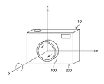
- FIG. 3 is a diagram showing the coordinate system of the camera.
- FIG. 4 is a diagram showing an example of posture determination and moving image division.
- FIG. 5 is a flowchart showing the processing of the imaging method.
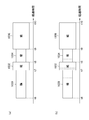
- FIG. 6 is a diagram showing a state of divided recording of a moving image.
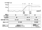
- FIG. 7 is a diagram showing a change in the attitude of the camera and division and storage of a moving image.
- FIG. 8 is a diagram showing an example of a folder structure.
- FIG. 9 is another diagram showing an example of the folder structure.
- FIG. 10 is a diagram showing an example of icon display of a moving image file.
- FIG. 10 is a diagram showing an example of icon display of a moving image file.
- FIG. 11 is a diagram showing a state in which thumbnail images are attached to icons of moving image files.
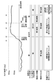
- FIG. 12 is a diagram showing an example of scene narrowing-down display based on file information.
- FIG. 13 is another flowchart showing the processing of the imaging method.
- FIG. 14 is a diagram showing another example of posture determination and moving image division.
- FIG. 15 is a diagram showing still another example of posture determination and moving image division.
- FIG. 16 is a diagram showing still another example of posture determination and moving image division.
- FIG. 17 is a diagram showing still another example of posture determination and moving image division.
- FIG. 18 is another flowchart showing the processing of the imaging method.
- FIG. 19 is still another flowchart showing the processing of the imaging method.
- FIG. 20 is a diagram showing how a moving image file is resized and played back.
- FIG. 21 is another diagram showing how the size of a moving image file is changed and reproduced.
- FIG. 22 is a flow chart showing the moving image recording processing in the first mode and the second mode.
- FIG. 23 is a flowchart (continuation of FIG. 22) showing the moving image recording processing in the first mode and the second mode.
- FIG. 24 is a diagram showing an example of a folder structure regarding the first mode and the second mode.
- FIG. 25 is a diagram showing how to select a frame to be extracted as a still image.
- FIG. 26 is an external view of a smartphone according to the second embodiment.
- FIG. 27 is a block diagram showing the configuration of the smartphone according to the second embodiment.
- FIG. 28: is a figure which shows the attitude
- FIG. 29 is a diagram showing how the posture of the smartphone is determined based on the angle.
- FIG. 1 is a diagram showing the configuration of a camera 10 (imaging device) according to the first embodiment.
- the camera 10 includes an interchangeable lens 100 (photographing unit, image pickup device) and an image pickup device main body 200 (photographing unit, image pickup device). Form an image.
- the interchangeable lens 100 and the imaging device main body 200 can be attached and detached via a mount (not shown).
- the interchangeable lens 100 includes a zoom lens 110, a focus lens 120, a diaphragm 130, and a lens driving unit 140.
- the lens driving unit 140 drives the zoom lens 110 and the focus lens 120 forward and backward in response to a command from the image processing device 240 (lens drive control unit 240F in FIG. 2) to perform zoom (optical zoom) adjustment and focus adjustment.
- the zoom adjustment and the focus adjustment may be performed according to a command from the image processing device 240, or may be performed according to a zoom operation or a focus operation (a zoom ring (not shown), a rotation of the focus ring, or the like) performed by the user. Good.
- the lens driving unit 140 controls the diaphragm 130 according to a command from the image processing device 240 to adjust the exposure.
- information such as the positions of the zoom lens 110 and the focus lens 120 and the opening degree of the diaphragm 130 is input to the image processing device 240.
- the interchangeable lens 100 has an optical axis L.
- the imaging device main body 200 includes an imaging device 210 (imaging unit), an AFE 220 (AFE: Analog Front End, imaging unit), an A/D converter 230 (A/D: Analog to Digital, imaging unit), an image processing device 240, An operation unit 250, a storage unit 260, a monitor 270, and a posture sensor 280 (direction detection unit) are provided.
- the image pickup apparatus main body 200 may have a shutter (not shown) for blocking the light transmitted through the image pickup element 210.
- the image sensor 210 has a light receiving surface in which a large number of light receiving elements are arranged in a matrix.
- the subject light transmitted through the zoom lens 110, the focus lens 120, and the diaphragm 130 is imaged on the light receiving surface of the image pickup element 210, and converted into an electric signal by each light receiving element.
- An R (red), G (green), or B (blue) color filter is provided on the light receiving surface of the image sensor 210, and a color image of the subject can be acquired based on the signals of the respective colors.
- the image pickup device 210 various photoelectric conversion devices such as a CMOS (Complementary Metal-Oxide Semiconductor) and a CCD (Charge-Coupled Device) can be used.
- the AFE 220 performs noise removal and amplification of the analog image signal output from the image sensor 210, and the A/D converter 230 converts the captured analog image signal into a digital image signal having a gradation width.
- FIG. 2 is a diagram showing a functional configuration of the image processing device 240.
- the image processing device 240 includes an image acquisition unit 240A, a direction detection unit 240B (direction detection unit), a control unit 240C (control unit), an event detection unit 240D (event detection unit), and a still image extraction unit 240E (still image extraction unit). , And a lens drive control unit 240F (lens drive control unit). Then, the image processing device 240 takes a moving image based on the digital image signal input from the A/D converter 230, generates a file, generates a still image file, processes a plurality of frames forming the moving image, and extracts a still image. Etc. are processed. Details of the processing by the image processing device 240 will be described later.
- the function of the image processing device 240 can be realized by using various processors.
- the various processors include, for example, a CPU (Central Processing Unit), which is a general-purpose processor that executes software (programs) to realize various functions.
- the various processors described above also include programmable logic devices (PLDs) such as GPUs (Graphics Processing Units) and FPGAs (Field Programmable Gate Arrays) that are processors specialized for image processing.
- PLDs programmable logic devices
- GPUs Graphics Processing Units
- FPGAs Field Programmable Gate Arrays
- a programmable logic device is a processor whose circuit configuration can be changed after manufacturing.
- the above-described various processors also include a dedicated electric circuit, which is a processor having a circuit configuration specifically designed to execute a specific process such as an ASIC (Application Specific Integrated Circuit).
- ASIC Application Specific Integrated Circuit
- the processor When the above-described processor or electric circuit executes software (program), the processor (computer) readable code of the software to be executed is stored in a non-transitory recording medium such as a ROM (Read Only Memory). The processor then references the software.
- the software stored in the non-temporary recording medium includes a program for executing the imaging method according to the present invention.
- the code may be recorded in a non-temporary recording medium such as various magneto-optical recording devices and semiconductor memories instead of the ROM.
- a RAM Random Access Memory
- EEPROM Electrically Erasable and Programmable Read Only Memory
- the image processing device 240 includes a ROM 242 in addition to the above units.
- a computer-readable code of a program (including a program for executing the imaging method according to the present invention (a program according to the present invention)) necessary for image capturing, recording, display, and the like is recorded in the ROM 242.
- the operation unit 250 has a release button (not shown), operation buttons (for example, a cross button, a Quick button, an OK button, etc.), a dial, a switch, and the like, and the user can set a shooting mode, a moving image shooting instruction, a still image extraction instruction, and the like. Various operations can be performed.
- the monitor 270 may be used as the operation unit 250.
- the storage unit 260 (storage unit) is composed of various magneto-optical recording media, non-temporary recording media such as semiconductor memories, and its control circuit, and stores moving images, still images, still images extracted from the moving images, and the like.
- the recording medium a type that can be attached to and detached from the image pickup apparatus main body 200 can be used.
- the captured image (moving image, still image) may be transmitted to and stored in an external recording medium (storage unit) by, for example, wireless communication.
- the monitor 270 (display device) is configured by a touch panel type liquid crystal display panel, and can display a moving image, a still image, a still image extracting frame, and the like.
- the monitor 270 can be arranged on the back surface side, the top surface side, or the like of the imaging device body 200. Further, the camera 10 may include a finder.
- the camera 10 can set a still image shooting mode, a moving image shooting mode for still image extraction (first moving image mode), or a normal moving image shooting mode (second moving image mode) as a shooting mode.
- the still image shooting mode and the normal moving image shooting mode are the same as those of a normal digital camera.
- the moving image shooting mode for still image extraction is a mode in which still images can be extracted from a moving image file, and moving images with different shooting conditions from the normal moving image shooting mode Movie).
- the still image extraction moving image shooting mode at least one of the shutter speed, the autofocus speed, the automatic exposure follow-up speed, and the white balance follow-up speed is set to a higher speed than the normal moving image shoot mode, And/or the frame rate is set higher than in the normal moving image shooting mode.
- the resolution and frame rate are set to the highest values that can be set by the camera 10 (for example, 4,000 ⁇ 2,000 pixels, 30 frames/second), and the color tone is also set on the premise of still image extraction.
- the upper limit of ISO sensitivity is also set higher than in the normal moving image shooting mode.
- the shutter speed is set to a value corresponding to the frame rate of a moving image to be recorded in the normal moving image shooting mode (1/30 seconds when the frame rate is 30 frames/second).
- the speed is set higher than the frame interval (for example, less than 1/30 seconds).
- the shutter speed is set to a value corresponding to the frame rate of the moving image so that a smooth moving image is reproduced, but in this case, a moving subject may be blurred.
- the shutter speed is set to a higher speed than the normal movie shooting mode (higher than the frame interval) to extract high-quality still images with less subject blurring. Will be possible.
- the shutter speed can be increased by increasing the upper limit of ISO (International Organization for Standardization), and a still image with less blur can be extracted.
- the autofocus speed, the auto exposure tracking speed, the auto white balance tracking speed, and the like are set to be higher than those in the normal moving image shooting mode. As a result, it is possible to acquire many frames in which the subject is in focus, frames with proper exposure, and the like.
- setting a high rate also shortens the frame interval of the moving image and increases the number of frames that can be extracted as a still image.
- the frames forming the moving image can be extracted as a still image afterwards. Therefore, the user can easily take a picture of an event (natural phenomenon, accident, happening, etc.) that is unknown when it will occur, a picture of a subject whose state changes over time or a momentary state of a moving subject, etc. be able to.
- the still image can be extracted not only at the timing at which the recording of the still image is instructed but also at other timings. Therefore, the user can acquire a still image at a desired timing.
- a high-quality still image can be extracted by setting shooting conditions (shutter speed, resolution, frame rate, etc.) suitable for still image extraction.
- still images can be shot (saved) during moving image shooting.
- FIG. 3 is a diagram showing an example of a coordinate system defined for the camera 10.
- the X-axis is the optical axis direction (direction toward the subject)
- the Z-axis is the direction toward the upper side of the imaging device main body 200
- the (X-axis, Y-axis, Z-axis) is the coordinate of the right-handed system.
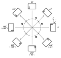
- FIG. 4 is a diagram showing an example of the relationship between the angle around the X axis and the posture (vertical or horizontal).
- the direction detection unit 240B determines "horizontal" when the angle is in the range of (-45 deg or more +45 deg or less) and (+135 deg or more +225 deg or less), and determines "vertical” otherwise. can do.
- the direction detection unit 240B determines the camera based on the measurement result of the attitude sensor 280. It is possible to detect 10 postures (directions with respect to the direction of gravity).
- the range of angles shown in FIG. 4 is an example, and the posture may be determined in a range different from this.
- the direction detection unit 240B may determine "horizontal" when the angle is in the range of (-30 deg or more and +30 deg or less) and (+150 deg or more and +210 deg or less), and may determine "vertical” otherwise. .
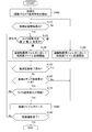
- FIG. 5 is a flowchart showing processing in the still image extracting moving image shooting mode (first moving image mode).
- the flowchart in FIG. 5 shows one aspect of the imaging method according to the present invention, and can be executed using the program according to the present invention (the same applies to other flowcharts described later).
- the control unit 240C sets the photographing unit (the interchangeable lens 100, the image sensor 210, the AFE 220, the A/D converter 230) to the first moving image mode.
- the process of FIG. 5 is started, and the control unit 240C initializes the state of the camera 10 (acquisition and display of live view image, initialization of posture, start of posture determination, etc.) (step S100: initialization step). ..
- the control unit 240C determines whether or not a moving image recording start instruction has been given (step S110: shooting step, moving image generation step).
- the control unit 240C can determine that “a moving image recording start instruction has been issued”, for example, when a release button (not shown) of the operation unit 250 is pressed. If the determination is positive, the process proceeds to step S120.
- the direction detection unit 240B detects the attitude (direction with respect to the gravity direction) of the camera 10 (imaging device) based on the output of the attitude sensor 280 (step S120: attitude detection step, determination step). As described above with reference to FIGS. 3 and 4, the direction detection unit 240B determines whether the posture is “vertical”, “horizontal”, or “indefinite” depending on the angle around the X axis.
- the posture “undefined” may include a state in which the angle around the Y axis is large and “vertical” or “horizontal” cannot be specified, such as when the user is holding the camera 10 toward the ground or the sky. .. Note that the direction detection unit 240B may not detect the “undefined” state of the camera 10.
- step S120 When it is determined in step S120 that the attitude of the camera 10 is “horizontal” or “undefined”, the control unit 240C compresses the moving image captured by the image capturing unit to generate a new moving image file. Then, the control unit 240C starts recording (saving) of the horizontal moving image file in the vertical/horizontal moving image folder (first folder) of the storage unit 260 (step S130: moving image saving step).
- the control unit 240C can compress a moving image in the MPEG format (MPEG2, MPEG4, etc.), for example.
- the control unit 240C compresses the moving image captured by the capturing unit and generates a new moving image file. Then, the control unit 240C starts recording (saving) of the vertical moving image file in the same vertical and horizontal moving image folder (first folder) as the horizontal moving image (step S140: moving image saving step).
- the control unit 240C may also record and store the sound with a microphone (not shown) provided in the camera 10.
- the "horizontal moving image” and the "vertical moving image” are moving images when the posture is horizontal or indefinite, and the "vertical moving image folder” is a folder for storing the vertical moving image and the horizontal moving image.
- the direction detection unit 240B continues the posture detection of the camera 10 in parallel with the shooting of the moving image and determines "whether or not the direction change with respect to the gravity direction of the camera 10 (imaging device) has occurred" (step S170: determination step). .. “Whether or not the direction has changed” can be determined based on the output of the attitude sensor 280 (for example, acceleration in the three axis directions).
- the control unit 240C closes the moving image file being recorded and divides the moving image (step S180: moving image generating step). In this case, the control unit 240C denies the determination of step S190 and returns to step S120.
- the control unit 240C determines whether the attitude of the camera 10 is "vertical”, “horizontal”, or "indefinite” as at the start of recording the moving image file. Then, according to the result, the control unit 240C saves a new moving image file related to the division (a different moving image file from that before the division) in the vertical and horizontal moving image folder of the storage unit 260 (the same folder as before the division). .. For example, when the attitude of the camera 10 changes from “horizontal” at the start of recording to “vertical”, the control unit 240C sets the horizontal moving image file (first moving image file of the first moving image) in the vertical/horizontal moving image folder at the start of recording.
- step S170 when the posture of the camera changes again (Yes in step S170), the moving image may not be closed. This is because the number of video files may increase too much if the video is repeatedly divided every time the attitude of the camera changes.
- the image acquisition unit 240A, the direction detection unit 240B, and the control unit 240C divide the moving image according to the posture of the camera 10 and save the moving image file until the moving image shooting ends (while the determination in step S190 is No). Continue to do.
- the direction detection unit 240B and the control unit 240C add information regarding the posture (direction with respect to the gravity direction) of the camera 10 to the first moving image file and the second moving image file, and display the icon of the moving image file or reproduce the moving image. It is preferable to be able to refer to.
- the direction detection unit 240B and the control unit 240C can record information about the posture of the camera 10 (information about the direction with respect to the gravity direction) in the header or footer. For example, "01" can be set for the vertical direction, "02" for the horizontal direction, and "03” for other (oblique, indefinite, etc.).
- FIG. 6 is a diagram showing a state of divided recording of a moving image.
- the upper part of the figure shows a state in which moving image frames 1001 to 1005 are sequentially recorded.
- the posture of the camera 10 is switched from "horizontal or indefinite” to "vertical” (Yes in step S170) at the time of recording up to the frame 1002 (frame number: N-1).
- the control unit 240C closes the moving image file 1010 (first moving image file) being recorded and divides the moving image (step S180: moving image generating step).
- the control unit 240C starts recording the moving image starting from the frame 1003 (frame number: N) as a new moving image file 1020 (second moving image file) (step S140).
- the control unit 240C stores the moving image files 1010 and 1020 in the same folder (vertical and horizontal moving image folder) in the storage unit 260.
- FIG. 7 is a diagram showing an example of determining a direction change based on an angle around the X axis.
- the posture is “horizontal” between the elapsed time of zero and t1 and that the angle exceeds 45 deg (threshold value) and is “vertical” at the elapsed time t1.
- the moving image is divided at time t1.
- the control unit 240C saves the moving image file (first moving image file) of the first moving image whose elapsed time is from 0 to t1 in the vertical and horizontal moving image folder (first folder), and the moving image file of the second moving image after the elapsed time t1 ( The second moving image file) is also saved in the vertical and horizontal moving image folder (first folder). Since the posture of the camera 10 may change slightly, the control unit 240C may determine that “the posture has changed” when the state in which the posture has changed continues for a predetermined time or longer. Further, although FIG.
- the same processing can be performed when the attitude changes from vertical to horizontal (in this case, the vertical moving image is the first moving image and the horizontal moving image is the horizontal moving image).
- the video is the second video, and so on for other aspects).
- step S150 the control unit 240C determines in step S150 that “there is a video recording end instruction (video shooting end instruction),” and step S160 is “ Even when it is determined that the remaining capacity of the recording medium is not sufficient”, the moving image file is closed (step S180). However, the control unit 240C also ends the shooting of the moving image in these cases (Yes in step S190).
- step S150 the control unit 240C may determine that "the motion picture recording end instruction has been given", for example, when the release button (not shown) of the operation unit 250 is pushed down or when the end instruction is given via the monitor 270. it can.
- the end timing of the second moving image (vertical moving image; moving image in the vertical state) is set by the user.
- the end timing of the first moving image is the user's first moving image end instruction or moving image.
- the shooting end instruction corresponds to a shooting end instruction.
- a moving image is thus determined when it is determined that “the direction (posture) of the camera 10 (imaging device) with respect to the gravity direction has changed in the still image extracting moving image shooting mode (first moving image mode)”.
- first moving image mode the still image extracting moving image shooting mode
- second moving image To generate a horizontal moving image (first moving image) and a vertical moving image (second moving image).
- the generated horizontal moving image moving image file (first moving image file) and vertical moving image moving image file (second moving image file) are stored in the vertical and horizontal moving image folder (first folder).
- the user can easily identify the posture of the camera 10 when each moving image is captured, and can easily select a moving image including a frame to be extracted as a still image by using the posture of the camera 10 as a clue. Moreover, the user can search for a desired frame quickly because the frame to be extracted as a still image can be searched in a moving image whose recording time has been shortened by dividing the frame. As described above, according to the first embodiment, the user can quickly and easily select a moving image frame having a desired composition.
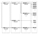
- FIG. 8 is a diagram showing an example of a folder structure for storing a moving image.
- the control unit 240C creates a folder for each shooting date, and a folder is created for each shooting number in the folder for each shooting date.
- a folder structure can be displayed on the monitor 270 (display device) by the control unit 240C.
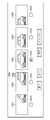
- FIG. 9 shows a state in which vertical and horizontal moving image folders (first folders) having different shooting numbers are displayed on the monitor 270 by icons indicating the respective folders.
- FIG. 10 is a diagram showing an example of icon display of a moving image file.
- the control unit 240C displays a moving image file of a horizontal moving image with the characters "horizontal moving image” added to the horizontal icon and the characters "vertical moving image” added to the vertical icon. The symbol in the icon indicates that the file can be played back by designating it.
- the control unit 240C stores the moving image files of the horizontal moving image and the vertical moving image (first moving image file, second moving image file) in the same folder of the storage unit 260.
- FIG. 10 is a diagram showing an example of icon display of a moving image file.
- the control unit 240C displays a moving image file of a horizontal moving image with the characters "horizontal moving image” added to the horizontal icon and the characters “vertical moving image” added to the vertical icon.
- the symbol in the icon indicates that the file can be played back by designating it.
- the control unit 240C stores the moving image files of the horizontal moving image and the vertical moving image (first moving image file, second moving
- the file name is the file creation date (October 23, 2018), the shooting number (001), vertical and horizontal identification information (horizontal video is H (Horizontal), vertical video is V (Vertical)), .., a file size (10 MB, etc.), and an extension (“.mpg” in this case).
- a horizontal moving image file (first moving image file) and a vertical moving image file (second moving image file) have a common part except for the file name extension.
- the vertical/horizontal identification information is an example of information on the direction of the camera 10 (imaging device) with respect to the gravity direction.
- the control unit 240C may include the information indicating the file type, the file creation date and time, and the vertical/horizontal identification information in the file name. For example, the control unit 240C assigns the file name “IMG201810112230_H.MOV” to the horizontal moving image file created on 2018/1/1 12:30 and creates the file name on 2018/1/1 12:40. A file name of "IMG201201101240_V.MOV" can be given to a vertical moving image file. In the file name, "IMG” is an example of information indicating that it is an image file. Also in this case, the file name may include information indicating the file size.
- FIG. 11 is a diagram showing a state in which a thumbnail image is displayed on the icon of a moving image file.
- Part (a) of the figure is an example of a horizontal moving image
- part (b) is an example of a vertical moving image.
- the image to be displayed may be the first frame of a horizontal moving image or a vertical moving image, or a frame in the middle (for example, a frame in which an event has occurred).
- the control unit 240C can display icons, thumbnails, and file names of moving image files.
- FIG. 12 is a diagram showing an example of scene narrowing-down display based on file information.
- the portion (a) of the figure shows the horizontal moving image file 1030, the vertical moving image file 1032, and the horizontal moving image file 1030 from the elapsed time t6 to t7, the elapsed time t7 to t8, the elapsed time t8 to t9, and the elapsed time t9 to t10, respectively.
- a state in which the file 1034 and the vertical moving image file 1036 are recorded is shown.
- the control unit 240C refers to the file information such as the file name, and displays each moving image file on the monitor 270 (or an external display device) by a graphic such as a rectangle having a width corresponding to the length of the recording time.
- the control unit 240C may perform identification display such that different colors are used for the vertical moving image and the horizontal moving image for the figure indicating the moving image file.
- the recording time of the horizontal moving image file 1030 and the vertical moving image file 1036 is long.
- the control unit 240C displays the selected moving image file or some frames constituting the moving image file on the monitor 270 or the outside. Can be displayed on the display device. This allows the user to select a desired frame to be extracted as a still image (see the section "Extraction of still image” described later and FIG. 25).
- control unit 240C may also display the timing at which the event occurred.
- the timing at which the event detection unit 240D detects an event is indicated by a dotted line in the rectangle indicating the moving image file.
- FIG. 13 is a flowchart showing the processing in mode 1, and the direction detection unit 240B determines whether the posture (direction with respect to the gravity direction) of the camera 10 is “horizontal”, “vertical”, or “changing”.
- Step S122 Posture detection step
- the control unit 240C starts recording (saving) of a moving image file (first moving image file) in the vertical and horizontal moving image folder (first folder) as a horizontal moving image (first moving image) (step). S130).
- the control unit 240C starts recording in the vertical/horizontal moving image folder (first folder) as a vertical moving image (second moving image) when the posture is “vertical” (step S140), and changes when the posture is “changing”. Recording is started in the changing moving image folder (third folder) as a medium moving image (third moving image) (step S124).
- the control unit 240C can create a changing moving image folder in addition to the vertical and horizontal moving image folders in the lower hierarchy of the folder of each shooting number.
- the direction detection unit 240B determines that “the posture change of the camera 10 has started or completed” (Yes in step S172 (determination step))
- the moving image is divided (closed moving image file, new moving image file Generate).
- the direction detection unit 240B determines that the posture change has started when the angle around the X axis changes by a predetermined value or more for a certain period of time. .
- the direction detection unit 240B determine that “the posture change is completed” when the time within which the change in the angle falls within the determined range continues for a certain time or more. For example, in the example shown in FIG. 14, the angle greatly changes between the elapsed times t1 and t2, and the angle is stable between the elapsed times t3 and t4.
- the direction detection unit 240B determines that "the posture is changing" from the elapsed time t2 to t4 and determines that "the posture change is completed" at the elapsed time t4 (determination of the actual posture and the posture of the camera 10). Considering the time lag until the result changes).
- the control unit 240C displays the horizontal moving image (first moving image; zero elapsed time to t2) and the vertical moving image (second moving image; elapsed time t4 or later) in time from the elapsed time t2 to t4.
- a changing moving image (third moving image) in between is generated.
- the moving image during the change includes the moving image during the first period in which the attitude of the camera 10 is changing (direction change is occurring).
- the direction detecting unit 240B determines that the period (second period) from the elapsed time t4 to t5 is “in addition to the period (first period) from the elapsed time t2 to t4. The posture of the camera 10 has changed.”
- the third moving image includes the moving image in the second period after the direction change is completed.
- the control unit 240C divides the moving image into a moving image file (third moving image file) different from the horizontal moving image (first moving image) and the vertical moving image (second moving image), and sets the vertical and horizontal moving image folder (third moving image folder). It can be recorded in one folder). However, the third moving image may be recorded in an independent changing moving image folder (third folder).
- An image during a posture change or during a period when the shooting condition is unstable may be less important, but in aspect 3, such a period is saved as a moving image different from a horizontal moving image and a vertical moving image, and thus extracted as a still image. You can easily select the frames you want and organize the video files and folders.
- Mode 5 Mode in which no moving image is recorded while the posture is changing
- the moving image is recorded during the period during the posture change (and the period until the posture is stabilized thereafter), but a mode in which the moving image is not recorded during the posture change can also be adopted.
- the direction detection unit 240B indicates that "the orientation of the camera 10 is horizontal (first state), vertical (second state), or changing (third state)."""Arethere?" is detected (step S122). Then, if the posture is changing, recording of the moving image file is not started (return to step S122).
- step S130 and S140 when the orientation of the camera 10 is horizontal or vertical and the orientation change of the camera 10 starts after the recording of the moving image is started (steps S130 and S140) (Yes in step S174), the control unit 240C determines the moving image file in step S180. Is closed and the process returns to step S122. Then, recording of the moving image is restarted after the posture of the camera 10 becomes horizontal or vertical (steps S130 and S140).
- the image during posture change may be less important, but in mode 5, since the moving image is not stored during such a period, the remaining capacity of the recording medium can be saved.
- the user can easily select frames to be extracted as still images and organize moving image files and folders.
- Aspect 6 shown in the flowchart of FIG. 19 is an aspect when the posture change of the camera 10 is started or completed.
- the control unit 240C Does not close the moving image file (Yes in step S176 and does not proceed to step S180). Therefore, in this case, the moving image is not divided. The same applies not only when a specific event has occurred up to a certain time ago, but also when a specific event is occurring (continuing).
- the control unit 240C sets the value of T (for example, 30 seconds can be set, but other values may be used) in response to the user's operation via the operation unit 250 or irrespective of the user's operation.
- You can Whether or not a specific event has occurred is determined by the event detection unit 240D (see FIG. 2) by automatically detecting the amount of movement of the subject, the change in size and shape, the change in brightness, etc. by known image processing. May be. Further, whether or not a specific event has occurred may be determined by a user's instruction via the operation unit 250 (including the case where the monitor 270 is used as a touch panel). Further, it may be determined that the “event has occurred” when the user gives an instruction to shoot a still image during shooting of a moving image.
- the event detection unit 240D and the control unit 240C preferably add information indicating the event detection timing to the moving image file (for example, record it in a header or footer). By referring to this information, the user can quickly and easily select a frame to be extracted as a still image (described later).
- FIG. 19 the flowchart in FIG. 19 is based on FIG. 13 (a mode in which the moving image whose posture is changing is a moving image different from the horizontal moving image and the vertical moving image and is stored in another folder). Good.
- control unit 240C also determines which mode, including the above-described modes 1 to 6, for dividing and recording (saving) the moving image in accordance with the user's operation via the operation unit 250. Good.
- the camera 10 can display a stored moving image (or a still image extracted from the moving image) on a display device such as the monitor 270.
- the moving image may be horizontally shot (shooting when the camera 10 is in the “horizontal” state) or vertically shot (shooting when the camera 10 is in the “vertical” position). If the size of the captured image is maintained and displayed in a direction different from that at the time of capturing, problems such as "a part of the image is not displayed" may occur.
- the control unit 240C changes the size of the image in the vertical direction and/or the horizontal direction based on the relationship with the posture of the camera 10 at the time of shooting and displaying. can do.
- the attitude of the camera 10 at the time of shooting can be grasped by referring to the file information such as the file name and the information in the header.
- FIG. 20 is a diagram showing an example of changing the size of an image.
- Portion (a) of the same figure is an example (displayed in the same direction as at the time of image capturing) in which a horizontally captured image 1040 is displayed on the monitor 270 (display device) while the camera 10 is horizontally oriented. In this case, it is not necessary to change the size of the image 1040.
- part (b) of the figure is an example in which the image is displayed in a state in which the camera 10 is in the portrait orientation (displayed in a different orientation from that at the time of shooting). In this case, if the image 1040 is displayed as it is, all the images cannot be displayed.
- FIG. 21 is a diagram showing another example of changing the size of an image.
- Portion (a) of the figure is an example in which a vertically captured image 1044 is displayed in a state in which the camera 10 is oriented vertically. In this case, it is not necessary to change the size of the image 1044.
- the size change illustrated in FIGS. 20 and 21 may be performed in one of the vertical direction and the horizontal direction, or both.
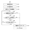
- the controller 240C determines whether the camera 10 is in the first moving image mode (still image extracting moving image mode) or the second moving image mode (normal moving image mode) (step S112). In the case of the first moving image mode, the control unit 240C sets shooting conditions suitable for the first moving image mode (step S114).
- the shooting conditions set in step S114 are, as described above in the "shooting mode" section, the shooting conditions that emphasize extraction of a still image rather than viewing the moving image itself.
- the processes in and after step S114 in the first moving image mode are the same as those in the flowchart of FIG. 5, and thus detailed description thereof will be omitted.
- step S112 when the result of the determination in step S112 is the second moving image mode, the control unit 240C sets the shooting condition suitable for the second moving image mode (step S191 in FIG. 23).
- the direction detection unit 240B determines the attitude of the camera 10 (step S192), and the control unit 240C starts generation and recording (saving) of a moving image file in the vertical/horizontal moving image folder (first folder) of the storage unit 260 (step).
- step S193 Video saving step).
- the processing of steps S194 and S195 is the same as the processing of steps S150 and S160 for the first moving image mode.
- step S194 If there is an instruction to end the moving image recording (Yes in step S194) and the remaining capacity of the recording medium is not sufficient (No in step S195), the control unit 240C closes the moving image file (step S197), and the step of FIG. The process returns to S190 (determination as to whether or not moving image shooting has ended).
- the control unit 240C continues recording the moving image.
- the second moving image mode unlike the case of the first moving image mode, even when the direction detection unit 240B does not determine that “the posture change (direction change) of the camera 10 has occurred” (No in step S196), If it is determined that the posture has changed (Yes in step S196), the moving image is not divided.
- the moving image is not divided even if the attitude of the camera 10 changes.
- the second moving image mode is not a mode for shooting a moving image for the purpose of extracting a still image, This is because it is not necessary to divide the to make it easier to find a specific scene.
- FIG. 24 is a diagram showing an example of a folder structure in the case of considering the first mode and the second mode.
- the control unit 240C creates a folder for each shooting date, and creates a folder for the first moving image mode and a folder for the second moving image mode in the folder for each shooting date.
- the control unit 240C creates a folder for each shooting number in the folder of the first moving image mode, and saves a horizontal moving image and a vertical moving image in a number corresponding to the division of the moving image in the folder of each shooting number.
- the control unit 240C records the moving image file in the folder of the second moving image mode.
- the folders for the first and second moving image modes are provided under the folder for the shooting date, but the folders for the first and second moving image modes are for the upper level, and the folders for the shooting date are under the folders. It may be provided.
- Such a folder structure can be displayed on the monitor 270 (display device) by the control unit 240C.
- the camera 10 can extract the frames that make up a moving image as a still image.
- the moving image file recorded by the camera 10 may be used to extract a still image by another device such as a personal computer.
- the control unit 240C causes the monitor 270 to reproduce and display the file selected by the user among the moving image files of the horizontal moving image, the vertical moving image, or the changing moving image (first moving image, second moving image, third moving image).
- frame-by-frame reproduction one frame at a time according to a user operation
- the control unit 240C stops the reproduction by the user's operation, and fixes the selection of the frame displayed at the time of the stop according to the user's operation, so that the still image extraction unit 240E extracts the frame as a still image. ..
- the control unit 240C may display a plurality of frames including the frame in which the event is detected on the monitor 270 by referring to the information.
- FIG. 25 is an example of such a display, and five frames 1051 to 1055 including a frame 1052 are displayed.
- the frame 1052 in which a still image is recorded (still image recording is an example of event occurrence) is given a camera-like icon 1060 by the still image extraction unit 240E.
- the icon 1060 allows the user to recognize that the frame is a still image recorded.
- the range of the still image extraction frame to be displayed is a frame (frame 1051) and a frame (frame 1051) temporally before and after the “frame corresponding to the recorded still image file” (frame 1052 in the example of FIG. 25). 1053 to 1055) may be included. Further, the range of the still image extraction frame to be displayed may be a mode of “including only a frame preceding in time” or a mode of “including only a frame subsequent in time”. The range of the still image extraction frame to be displayed may be set according to the designation by the user, or may be set without depending on the designation by the user.
- the range of frames to be displayed may be specified by time (for example, 1 second before and after the frame in which a still image is recorded) or by the number of frames (for example, before and after the frame in which a still image is recorded). 10 frames each). Further, in the initial state, only the frames recorded as still images may be displayed as a list, and the frames selected from the frames may be displayed before and/or after the frame in time.
- the user can select a frame from the displayed still image extraction frames.
- the user can select a frame by checking the check box 1070 for a desired frame via the operation unit 250 and/or the monitor 270, and can also select a plurality of frames.
- the frame in which the still image designated by the user is recorded is not always recorded at the best timing. By displaying other related frames together, the user may want to select another frame. Therefore, it is preferable to be able to select from the frame before and/or after the frame in which the still image is recorded.
- FIG. 25 shows a state in which the user has selected a frame 1053 different from the frame in which the still image is recorded (frame 1052 with the icon 1060).
- the still image extraction unit 240E extracts the selected frame as a still image (still image extraction step). Since the moving image file is stored in a moving image format such as the MPEG format, the still image extraction unit 240E converts the data of the selected frame into the still image format (JPEG format or the like). The user can extract a still image at a desired timing from the moving images (first moving image, second moving image, third moving image).
- the configuration of the imaging device is not limited to this.
- the other imaging device of the present invention can be, for example, a built-in or external PC camera (PC: Personal Computer), or a portable terminal device having a photographing function as described below. .
- Examples of the mobile terminal device which is an embodiment of the image pickup device of the present invention include a mobile phone, a smartphone, a PDA (Personal Digital Assistants), and a portable game machine.
- a smartphone will be described as an example in detail with reference to the drawings.
- FIG. 26 is a diagram showing an appearance of a smartphone 1 (imaging device) which is an embodiment of an imaging device of the present invention, in which (a) is a front view and (b) is a rear view.
- a smartphone 1 shown in FIG. 26 has a flat housing 2, and a display panel 21 (display device) as a display unit and an operation panel 22 (operation unit) as an input unit on one surface of the housing 2. Is provided with a display input unit 20.
- the housing 2 includes a speaker 31, a microphone 32, an operation unit 40 (operation unit), and camera units 41 and 42 (imaging device, photographing unit, event detection unit, control unit, still image extraction unit, lens drive control). Section) and a strobe 43.
- the configuration of the housing 2 is not limited to this, and for example, a configuration in which the display unit and the input unit are independent may be employed, or a configuration having a folding structure or a slide mechanism may be employed.
- FIG. 27 is a block diagram showing the configuration of the smartphone 1 shown in FIG.
- a wireless communication unit 11 As main constituent elements of the smartphone 1, a wireless communication unit 11, a display input unit 20, a call unit 30, an operation unit 40, camera units 41 and 42, a flash unit 43, and a storage unit. 50 (storage unit), an external input/output unit 60, a GPS receiving unit 70 (GPS: Global Positioning System), a motion sensor unit 80, a power supply unit 90, and a main control unit 101.
- the main control unit 101 functions as a shooting unit, a moving image file generation unit, a still image file generation unit, an event detection unit, a display control unit, a still image extraction unit, and a lens drive control unit.
- a wireless communication function for performing mobile wireless communication via a base station device and a mobile communication network is provided as a main function of the smartphone 1.
- the wireless communication unit 11 performs wireless communication with the base station device accommodated in the mobile communication network according to an instruction from the main control unit 101. Using such wireless communication, various file data such as voice data and image data, electronic mail data and the like are transmitted and received, and web data and streaming data are received.
- the display input unit 20 displays an image (still image and/or moving image), character information, and the like to visually convey the information to the user, and also to perform a user operation on the displayed information. It is a so-called touch panel for detection, and includes a display panel 21 and an operation panel 22.
- an LCD Liquid Crystal Display
- an OELD Organic Electro-Luminescence Display
- the operation panel 22 is a device for visually recognizing an image displayed on the display surface of the display panel 21 and detecting one or a plurality of coordinates operated by a conductor such as a finger of a user or a pen.
- a conductor such as a finger of a user or a pen
- the operation panel 22 outputs a detection signal generated due to the operation to the main control unit 101.
- the main control unit 101 detects the operation position (coordinates) on the display panel 21 based on the received detection signal.
- the display panel 21 and the operation panel 22 of the smartphone 1 exemplified as one embodiment of the image pickup apparatus of the present invention constitute the display input unit 20 as one body. 22 is arranged to completely cover the display panel 21.
- the operation panel 22 may have a function of detecting a user operation even in an area outside the display panel 21.
- the operation panel 22 includes a detection area (hereinafter, referred to as a display area) for the overlapping portion that overlaps the display panel 21 and a detection area (hereinafter, a non-display area) for the other outer edge portion that does not overlap the display panel 21. Referred to)).
- the call unit 30 includes a speaker 31 and a microphone 32, converts a user's voice input through the microphone 32 into voice data that can be processed by the main control unit 101, and outputs the voice data to the main control unit 101. 11 or the audio data received by the external input/output unit 60 can be decoded and output from the speaker 31. Further, as shown in FIG. 26, for example, the speaker 31 can be mounted on the same surface as the surface on which the display input section 20 is provided, and the microphone 32 can be mounted on the side surface of the housing 2.
- the operation unit 40 is a hardware key that uses a key switch or the like, and is a device that receives an instruction from a user.
- the operation unit 40 is mounted on the side surface of the housing 2 of the smartphone 1 and is turned on when pressed by a finger or the like, and is turned off by a restoring force such as a spring when the finger is released. It is a button type switch.
- the storage unit 50 stores the control program and control data of the main control unit 101, application software, address data in which names and telephone numbers of communication partners are associated with each other, transmitted/received e-mail data, Web data downloaded by Web browsing, and It stores downloaded content data, and temporarily stores streaming data and the like. Further, the storage unit 50 includes an internal storage unit 51 with a built-in smartphone and an external storage unit 52 having a detachable external memory slot. The internal storage unit 51 and the external storage unit 52 that form the storage unit 50 are realized by using known storage media.
- the external input/output unit 60 serves as an interface with all external devices connected to the smartphone 1.
- the smartphone 1 is directly or indirectly connected to another external device via the external input/output unit 60 by communication or the like.
- means for communication and the like include universal serial bus (USB), IEEE 1394, and network (eg, Internet, wireless LAN).
- USB universal serial bus
- RFID Radio Frequency Identification
- IrDA Infrared Data Association
- UWB Ultra Wide Band
- Zigbee registered trademark
- jig registered trademark
- Examples of the external device connected to the smartphone 1 include a wired/wireless headset, a wired/wireless external charger, a wired/wireless data port, a memory card (Memory card) connected via a card socket, and a SIM (Subscriber).
- An Identity Module Card/UIM (User Identity Module Card) card may be used.
- an external audio and video device connected via an audio and video I/O (Input/Output) terminal an external audio and video device wirelessly connected, a smartphone connected wired/wireless, and a wired/wireless connected External devices such as a PDA, a personal computer connected by wire/wireless, and earphones can also be connected.
- the external input/output unit 60 can transmit the data transmitted from such an external device to each component inside the smartphone 1, or can transmit the data inside the smartphone 1 to the external device.
- the motion sensor unit 80 includes, for example, a triaxial acceleration sensor, a tilt sensor, and the like, and detects a physical movement of the smartphone 1 according to an instruction from the main control unit 101. By detecting the physical movement of the smartphone 1, the moving direction, acceleration, and posture of the smartphone 1 are detected. The detection result is output to the main control unit 101.
- the power supply unit 90 supplies power stored in a battery (not shown) to each unit of the smartphone 1 according to an instruction from the main control unit 101.
- the main control unit 101 includes a microprocessor, operates according to a control program and control data stored in the storage unit 50, and integrally controls each unit of the smartphone 1 including the camera unit 41. Further, the main control unit 101 includes a mobile communication control function for controlling each unit of the communication system and an application processing function for performing voice communication and data communication through the wireless communication unit 11.
- the main control unit 101 has an image processing function of displaying a video on the display input unit 20 based on image data (still image or moving image data) such as received data or downloaded streaming data.
- the image processing function means a function of the main control unit 101 decoding image data, performing image processing on the decoding result, and displaying an image on the display input unit 20.
- the camera units 41 and 42 are digital cameras (imaging devices) that electronically capture images using imaging devices such as CMOS and CCD. Under control of the main control unit 101, the camera units 41 and 42 convert the image data (moving image, still image) obtained by imaging into compressed image data such as MPEG or JPEG, and record it in the storage unit 50. In addition, it can be output through the external input/output unit 60 and the wireless communication unit 11. Also, the camera unit 41, under the control of the main control unit 101, performs division and combination of moving images, acquisition of high-quality still images (RAW images, etc.), frame replacement and processing, and extraction of still images from moving images. Can also In the smartphone 1 shown in FIGS. 26 and 27, one of the camera units 41 and 42 can be used for shooting, and the camera units 41 and 42 can be used simultaneously for shooting. When the camera unit 42 is used, the strobe 43 can be used.
- the camera units 41 and 42 can be used for various functions of the smartphone 1.
- the images acquired by the camera units 41, 42 can be displayed on the display panel 21, and the images of the camera units 41, 42 can be used as one of the operation inputs of the operation panel 22.
- the GPS receiving unit 70 detects the position
- the position can be detected by referring to the images from the camera units 41 and 42.
- the optical axis direction of the camera unit 41 of the smartphone 1 is determined without using the triaxial acceleration sensor or in combination with the triaxial acceleration sensor. It is also possible to judge the current usage environment.
- the images from the camera units 41 and 42 can be used in the application software.
- position information acquired by the GPS receiving unit 70 in image data of a still image or a moving image may be image data of a still image or a moving image
- voice information acquired by the microphone 32 may be voice information converted into text information by the main control unit or the like
- the posture information acquired by the motion sensor unit 80 may be added and recorded in the storage unit 50, or may be output through the external input/output unit 60 or the wireless communication unit 11.
- Part (a) of FIG. 28 is a diagram showing an example of a coordinate system defined for the smartphone 1, and in this example, the posture is determined by the angle around the X axis.
- the part (a) shows a vertical state at an angle of 0 deg (the second state in which the smartphone 1 (imaging device) is along the gravity direction), and the part (b) of the figure shows a lateral state at an angle of 90 deg (smartphone 1 (imaging device). ) Indicates the first state) along the horizontal direction.
- FIG. 29 is a diagram showing an example of the relationship between the angle around the X axis and the attitude (vertical or horizontal) of the smartphone 1. Note that, similarly to the case of the camera 10 according to the first embodiment (see FIG. 4 ), the posture and the state (first state) are set with the lateral state (state shown in part (b) of FIG. 28) as a reference (angle 0 deg). State, second state, third state) may be defined.
- the processing of the image capturing method according to the present invention (moving image capturing, division and recording, still image recording, still image extraction, etc.) is performed.
- the process executed by the image processing device 240 (each unit illustrated in FIG. 2) in the first embodiment (including the processes of Aspect 1 to Aspect 6) is performed.
- the unit 101 By being executed by the unit 101, it is possible to perform the processing of the imaging method according to the present invention.
- the functions of the operation unit 250, the storage unit 260, and the monitor 270 according to the first embodiment can be realized by the operation unit 40, the storage unit 50 and the operation panel 22, the display panel 21, and the operation panel 22 in the smartphone 1. it can.
- the smartphone 1 according to the second embodiment the same effect as that of the camera 10 according to the first embodiment (the user can quickly and easily select a moving image including a frame with a desired composition). Etc.) can be obtained.
Landscapes
- Engineering & Computer Science (AREA)
- Multimedia (AREA)
- Signal Processing (AREA)
- Physics & Mathematics (AREA)
- General Physics & Mathematics (AREA)
- Studio Devices (AREA)
- Television Signal Processing For Recording (AREA)
Abstract
本発明は、動画から静止画を抽出する際に、ユーザが所望の構図の動画フレームを迅速かつ容易に選択することができる撮像装置、撮像方法、及びプログラムを提供することを目的とする。本発明の第1の態様に係る撮像装置は、撮像装置であって、重力方向に対する撮像装置の方向を検出する方向検出部と、動画を撮影する撮影部と、制御部と、を備え、制御部は、撮影部が撮影した動画の動画ファイルを生成し、動画ファイルから静止画を抽出可能な第1動画モードを有し、制御部は、第1動画モードにおいて、方向検出部が撮像装置の重力方向に対する方向変化が起きたと判断した場合、動画を分割して第1動画と第2動画を生成し、制御部は、第1動画の第1動画ファイルと第2動画の第2動画ファイルを、記憶部の同一のフォルダに保存する。
Description
本発明は動画を撮影する撮像装置、撮像方法、及びプログラムに関し、特に動画を構成するフレームを静止画として抽出可能な撮像装置、撮像方法、及びプログラムに関する。
撮影後に静止画を抽出することを目的として動画を撮影する技術が知られている。この技術では、例えばいつ起こるか分からない一瞬の事象(イベント)を捉えるために動画を撮影及び記録しておき、撮影後にユーザが所望のフレームを選択するが、動画撮影中にいつイベントが発生するかは予測が難しい。そのため、ある程度の時間にわたって動画を撮影し続ける必要があり、記録メディアの残容量が切迫する、あるいは長時間の動画から所望のフレームをユーザが選択するのに非常に大きな労力を要する、といった課題がある。
そこで、上述した課題に対応する技術が提案されている。例えば特許文献1には、動画の撮影中にユーザの指示により静止画取得タイミングで動画にマーキングし、動画撮影終了後にマーキング箇所及びその前後の動画フレームを抽出及び表示することで、ユーザが動画における静止画抽出のタイミングを選択することを可能にする旨が記載されている。
しかしながら、上述した特許文献1に記載の技術ではマーキング情報が記録されるだけなので、マーキングしたフレームを抽出及び表示する度に画像ファイルの検索処理が必要であり、撮像装置への処理負荷が高い。また、特許文献1に記載の技術では撮影した動画全体に対して処理を行うため、抽出するフレームの選択に手間が掛かり、動画の撮影時間が長い場合はこの問題が顕著になる。さらに、特許文献1では静止画抽出用の動画を撮影している間の構図変化について考慮されていなかった。このため、従来の技術は、動画から静止画を抽出する際にユーザが所望の構図の動画フレームを迅速かつ容易に選択できるものではなかった。
本発明はこのような事情に鑑みてなされたもので、動画から静止画を抽出する際に、ユーザが所望の構図の動画フレームを迅速かつ容易に選択することができる撮像装置、撮像方法、及びプログラムを提供することを目的とする。
上述した目的を達成するため、本発明の第1の態様に係る撮像装置は、撮像装置であって、重力方向に対する撮像装置の方向を検出する方向検出部と、動画を撮影する撮影部と、制御部と、を備え、制御部は、撮影部が撮影した動画の動画ファイルを生成し、動画ファイルから静止画を抽出可能な第1動画モードを有し、制御部は、第1動画モードにおいて、方向検出部が撮像装置の重力方向に対する方向変化が起きたと判断した場合、動画を分割して第1動画と第2動画を生成し、制御部は、第1動画の第1動画ファイルと第2動画の第2動画ファイルを、記憶部の同一のフォルダに保存する。
通常、静止画撮影においては、ユーザは所望の構図に応じてカメラ(撮像装置)を横向き(カメラ底面が地面と平行)になるように、あるいは縦向き(カメラ底面が重力方向と平行)になるように構えて撮影する。これに対し動画撮影においては、撮影中に縦と横を切り替えることは少ない。一方、静止画の抽出を行うための動画撮影においては、事後的にフレーム切り出しを行うという特性上、動画撮影中にもカメラの構え方が縦と横で変化することが想定される。このような観点から、第1の態様では、重力方向に対する方向変化(撮像装置の姿勢の変化)が起きた場合に動画を分割して第1動画と第2動画を生成し、第1動画の第1動画ファイルと第2動画の第2動画ファイルを記憶部の同一のフォルダに保存する。この「同一のフォルダ」内において第1動画と第2動画とが別ファイルになっているので、各動画を撮影した際の撮像装置の姿勢を容易に識別でき、ユーザは所望の構図のフレームを含む動画を撮像装置の姿勢を手がかりにして迅速かつ容易に選択することができる。
また、第1動画ファイルと第2動画ファイルとを同一のフォルダに保存することで、連続したシーンを同一フォルダに保存することができ、フォルダ内でファイル情報のみからシーンの絞り込みを行うことができる。このため動画ファイルの検索処理に長時間を要することがない。また、動画ファイルの途中で姿勢が切り替わっている場合は表示方向の切り替えをファイルデコード中に行わなければならず、処理時間が不連続となり表示がスムーズに切り替わらないが、第1の態様では姿勢が変化したら動画を分割するので、ファイルを開く際に縦横方向の属性が分かり、ファイル先頭より一定間隔で表示の更新が可能となる。
また、静止画として抽出するフレームは分割され記録時間が短くなった動画の中で探せばよいので、所望のフレームを迅速に探すことができる。このように、第1の態様によれば、動画から静止画を抽出する際に、ユーザが所望の構図の動画フレームを迅速かつ容易に選択することができる。さらに、第1の態様ではタグやマーキング等の情報を用いる必要がないので、第1の態様で記録された動画に基づくと、フレームの選択や静止画の抽出を、他の撮像装置や画像再生装置、画像処理装置でも行うことができる。なお、動画ファイルを保存する記憶部は撮像装置に備えられたものでもよいし、外部の装置でもよい。
第2の態様に係る撮像装置は第1の態様において、制御部は、重力方向に対する撮像装置の方向に関する情報に基づいて、第1動画ファイルと第2動画ファイルを保存する。例えば、ファイル名もしくはその一部、動画ファイルのヘッダやフッタ等に情報を付与して保存することができる。
第3の態様に係る撮像装置は第1又は第2の態様において、制御部は、時間において、第1動画と第2動画の間にある第3動画を生成し、第3動画は、方向変化が起きた第1期間の動画を含む。第3の態様では、方向変化が起きている期間(第1期間)を第1,第2動画とは別の動画(第3動画)にして、方向変化が起きている期間をユーザが容易に識別できるようにしている。
第4の態様に係る撮像装置は第3の態様において、制御部は、第3動画を記憶部に保存をしない。第4の態様によれば、方向変化が起きている期間(第1期間)の動画を保存しないことで、記憶部の容量を節約することができる。
第5の態様に係る撮像装置は第3の態様において、制御部は、第3動画を同一のフォルダとは別のフォルダに保存する。第5の態様では、方向変化が起きている期間の動画(第3動画)を第1,第2動画を保存するフォルダとは別のフォルダにすることにより、第1,第2動画と第3動画とをユーザが容易に識別できるようにしている。
第6の態様に係る撮像装置は第3ないし第5の態様のいずれか1つにおいて、第3動画は、方向変化が終了した後の第2期間の動画も含む。方向変化が終了しても構図の変化に伴い撮影条件が安定していない可能性があるため、第6の態様では、方向変化が終了した後も第2期間においては第3動画に含めている。
第7の態様に係る撮像装置は第6の態様において、第2期間は、撮像装置が、動画の露出、動画のホワイトバランス、又は、動画中の被写体のフォーカスを調整している期間である。第7の態様は、第2期間の内容を具体的に規定するものである。
第8の態様に係る撮像装置は第1ないし第7の態様のいずれか1つにおいて、第1動画ファイルおよび第2動画ファイルは、ファイル名の拡張子を除く少なくとも一部が共通している。これにより、ユーザは第1動画ファイルと第2動画ファイルとが1つの動画を分割して生成されたファイルであることを容易に識別することができる。
第9の態様に係る撮像装置は第1ないし第8の態様のいずれか1つにおいて、制御部は、第1動画モードと撮影条件が異なる第2動画モードを有し、制御部は、第2動画モードにおいて、方向検出部が方向変化を検出した場合、動画を分割しない。例えば、動画からの静止画の抽出を前提としない通常の動画モードを第2動画モードとすることができる。
第10の態様に係る撮像装置は第9の態様において、第1動画モードは、第2動画モードに対してシャッタースピード、オートフォーカスの速度、自動露出の追従速度、ホワイトバランスの追従速度のうち少なくとも1つが高速に設定され、かつ/または第2動画モードに対してフレームレートが高く設定される。第10の態様は、第1動画モードと第2動画モードとの撮影条件の違いの一態様を規定するものであり、第1動画モードの撮影条件をこのように設定することで、動画から高画質な静止画を抽出することができる。
上述した目的を達成するため、本発明の第11の態様に係る撮像装置は撮像装置であって、重力方向に対する撮像装置の方向を検出する方向検出部と、動画を撮影する撮影部と、制御部と、を備え、制御部は、撮影部が撮影した動画の動画ファイルから静止画を抽出可能な第1動画モードと、第1動画モードと撮影条件が異なる第2動画モードを有し、制御部は、第1動画モードにおいて、方向検出部が撮像装置の重力方向に対する方向変化が起きたと判断した場合、動画を分割して第1動画と第2動画を生成し、制御部は、第2動画モードにおいて、方向検出部が、方向変化が起きたと判断した場合、動画を分割しない。第11の態様では、第1動画モードにおいて、重力方向に対する方向変化(撮像装置の姿勢の変化)が起きた場合に動画を分割して第1動画と第2動画を生成する。これにより各動画を撮影した際の撮像装置の姿勢を容易に識別でき、ユーザは静止画として抽出したいフレームを含む動画を撮像装置の姿勢を手がかりにして容易に選択することができる。なお、例えば動画からの静止画の抽出を前提としない通常の動画モードを第2動画モードとすることができる。
第12の態様に係る撮像装置は第11の態様において、制御部は、重力方向に対する撮像装置の方向に関する情報に基づいて、第1動画の第1動画ファイルと第2動画の第2動画ファイルを保存する。例えば、ファイル名もしくはその一部、動画ファイルのヘッダやフッタ等に情報を付与して保存することができる。
第13の態様に係る撮像装置は第11又は第12の態様において、制御部は、時間において、第1動画と第2動画の間にある第3動画を生成し、第3動画は、方向変化が起きている第1期間の動画を含む。第13の態様では、方向変化が起きている期間(第1期間)を第1,第2動画とは別の動画(第3動画)にして、ユーザが容易に識別できるようにしている。
第14の態様に係る撮像装置は第13の態様において、制御部は、第3動画を保存しない。第14の態様によれば、方向変化が起きている期間(第1期間)の動画を保存しないことで、記憶部の容量を節約することができる。
第15の態様に係る撮像装置は第13の態様において、制御部は、第3動画を第1動画を保存するフォルダ及び第2動画を保存するフォルダとは別のフォルダに保存する。第15の態様では、方向変化が起きている期間の動画(第3動画)を第1,第2動画を保存するフォルダとは別のフォルダにすることにより、第1,第2動画と第3動画とをユーザが容易に識別できるようにしている。
第16の態様に係る撮像装置は第13又は第14の態様において、第3動画は、方向変化が終了した後の第2期間の動画も含む。第16の態様は、方向変化が終了しても構図の変化に伴い撮影条件が安定していない可能性があるため、方向変化が終了した後も第2期間においては第3動画に含めている。
第17の態様に係る撮像装置は第16の態様において、第2期間は、撮像装置が、動画の露出、動画のホワイトバランス、又は、動画中の被写体のフォーカスを調整している期間である。第17の態様は、第2期間の内容を具体的に規定するものである。
第18の態様に係る撮像装置は第11ないし第17の態様のいずれか1つにおいて、第1動画の第1動画ファイルおよび第2動画の第2動画ファイルのファイル名は、少なくとも一部が共通している。これにより、ユーザは第1動画ファイルと第2動画ファイルとが1つの動画を分割して生成されたファイルであることを容易に識別することができる。
第19の態様に係る撮像装置は第2又は第12の態様において、制御部は、第1動画ファイルと第2動画ファイルに重力方向に対する撮像装置の方向に関する情報を付与する。
上述した目的を達成するため、本発明の第20の態様に係る撮像方法は、重力方向に対する撮像装置の方向を検出する方向検出部と、動画を撮影する撮影部と、撮影部が撮影した動画の動画ファイルから静止画を抽出可能な第1動画モードを有する制御部とを備える撮像装置の撮像方法であって、第1動画モードにおいて、方向検出部が撮像装置の重力方向に対する方向変化が起きたか否か判断する判断ステップと、方向検出部により、方向変化が起きたと判断された場合は、動画を分割して第1動画と第2動画を生成する生成ステップと、第1動画の第1動画ファイルと第2動画の第2動画ファイルを、記憶部の同一のフォルダに保存する保存ステップと、を備える。第20の態様によれば、第1の態様と同様に、第1動画モードにおいて重力方向に対する方向変化(撮像装置の姿勢の変化)が起きた場合に動画を分割して第1動画と第2動画を生成する。これにより各動画を撮影した際の撮像装置の姿勢を容易に識別でき、ユーザは動画から静止画を抽出する際に、ユーザが所望の構図の動画フレームを迅速かつ容易に選択することができる。なお、第20の態様において、第2~第10の態様と同様の構成をさらに備えていてもよい。
上述した目的を達成するため、本発明の第21の態様に係る撮像方法は、重力方向に対する撮像装置の方向を検出する方向検出部と、動画を撮影する撮影部と、撮影部が撮影した動画の動画ファイルから静止画を抽出可能な第1動画モード及び第1動画モードと撮影条件が異なる第2動画モードを有する制御部とを備える撮像装置の撮像方法であって、第1動画モードにおいて、方向検出部が撮像装置の重力方向に対する方向変化が起きたか否か判断する判断ステップと、方向検出部により、方向変化が起きたと判断された場合は、第1動画モードにおいて動画を分割して第1動画と第2動画を生成し、第2動画モードにおいて動画を分割しない動画生成ステップと、を有する。第21の態様によれば、第11の態様と同様に、第1動画モードにおいて重力方向に対する方向変化(撮像装置の姿勢の変化)が起きた場合に動画を分割して第1動画と第2動画を生成する。これにより各動画を撮影した際の撮像装置の姿勢を容易に識別でき、ユーザは動画から静止画を抽出する際に、ユーザが所望の構図の動画フレームを迅速かつ容易に選択することができる。なお、例えば動画からの静止画の抽出を行わない通常の動画モードを第2動画モードとすることができる。なお、第21の態様において、第12~第18の態様と同様の構成をさらに備えていてもよい。
上述した目的を達成するため、本発明の第22の態様に係るプログラムは、重力方向に対する撮像装置の方向を検出する方向検出部と、動画を撮影する撮影部と、撮影部が撮影した動画のファイルから静止画を抽出可能な第1動画モードを有する制御部とを備える撮像装置に用いられるプログラムであって、第1動画モードにおいて、方向検出部に撮像装置の重力方向に対する方向変化が起きたか否か判断させ、方向検出部により、第1動画モードにおいて方向変化が起きたと判断された場合、制御部に動画を分割させて第1動画と第2動画を生成させ、制御部に、第1動画の第1動画ファイルと第2動画の第2動画ファイルを、記憶部の同一のフォルダに保存させる。第21の態様により得られる効果は第20の態様と同様である。なお、第22の態様において、第2~第10の態様と同様の構成をさらに備えていてもよい。また、これら態様のプログラムのコンピュータ読み取り可能なコードを記録した非一時的記録媒体も、本発明の態様として挙げることができる。
上述した目的を達成するため、本発明の第23の態様に係るプログラムは、重力方向に対する撮像装置の方向を検出する方向検出部と、動画を撮影する撮影部と、撮影部が撮影した動画のファイルから静止画を抽出可能な第1動画モード及び第1動画モードと撮影条件が異なる第2動画モードを有する制御部とを備える撮像装置に用いられるプログラムであって、第1動画モードにおいて、方向検出部に撮像装置の重力方向に対する方向変化が起きたか否か判断させ、方向検出部により、第1動画モードにおいて方向変化が起きたと判断された場合、制御部に動画を分割させて第1動画と第2動画を生成させ、方向検出部により、第2動画モードにおいて方向変化が起きたと判断された場合、動画を分割させない。第23の態様により得られる効果は第21の態様と同様である。なお、第23の態様において、第12~第18の態様と同様の構成をさらに備えていてもよい。また、これら態様のプログラムのコンピュータ読み取り可能なコードを記録した非一時的記録媒体も、本発明の態様として挙げることができる。
以上説明したように、本発明の撮像装置、撮像方法、及びプログラムによれば、動画から静止画を抽出する際に、ユーザが所望の構図の動画フレームを迅速かつ容易に選択することができる。
以下、添付図面を参照しつつ、本発明に係る撮像装置、撮像方法、及びプログラムを実施するための形態について詳細に説明する。
<第1の実施形態>
<撮像装置の全体構成>
図1は第1の実施形態に係るカメラ10(撮像装置)の構成を示す図である。カメラ10は交換レンズ100(撮影部、撮像装置)及び撮像装置本体200(撮影部、撮像装置)により構成され、後述するズームレンズ110を含む撮影レンズにより被写体像(光学像)を撮像素子210に結像させる。交換レンズ100と撮像装置本体200とは、図示せぬマウントを介して装着及び取り外しすることができる。
<交換レンズの構成>
交換レンズ100は、ズームレンズ110と、フォーカスレンズ120と、絞り130と、レンズ駆動部140とを備える。レンズ駆動部140は、画像処理装置240(図2のレンズ駆動制御部240F)からの指令に応じてズームレンズ110、フォーカスレンズ120を進退駆動してズーム(光学ズーム)調整、フォーカス調整を行う。ズーム調整及びフォーカス調整は、画像処理装置240からの指令に応じて行う他に、ユーザが行ったズーム操作、フォーカス操作(図示せぬズームリング、フォーカスリングの回動等)に応じて行ってもよい。また、レンズ駆動部140は画像処理装置240からの指令に応じて絞り130を制御し、露出を調整する。一方、ズームレンズ110及びフォーカスレンズ120の位置、絞り130の開放度等の情報が画像処理装置240に入力される。なお、交換レンズ100は光軸Lを有する。
<撮像装置本体の構成>
撮像装置本体200は、撮像素子210(撮影部)、AFE220(AFE:Analog Front End、撮影部)、A/D変換器230(A/D:Analog to Digital、撮影部)、画像処理装置240、操作部250、記憶部260、モニタ270、及び姿勢センサ280(方向検出部)を備える。撮像装置本体200は、撮像素子210に透過させる光を遮光するためのシャッター(不図示)を有していてもよい。撮像素子210は、多数の受光素子がマトリクス状に配列された受光面を備える。そして、ズームレンズ110、フォーカスレンズ120、及び絞り130を透過した被写体光が撮像素子210の受光面上に結像され、各受光素子によって電気信号に変換される。撮像素子210の受光面上にはR(赤),G(緑),又はB(青)のカラーフィルタが設けられており、各色の信号に基づいて被写体のカラー画像を取得することができる。
なお、撮像素子210としては、CMOS(Complementary Metal-Oxide Semiconductor)、CCD(Charge-Coupled Device)等の様々な光電変換素子を用いることができる。AFE220は撮像素子210から出力されるアナログ画像信号のノイズ除去、増幅等を行い、A/D変換器230は、取り込んだアナログ画像信号を階調幅があるデジタル画像信号に変換する。
<画像処理装置の構成>
図2は、画像処理装置240の機能構成を示す図である。画像処理装置240は、画像取得部240A、方向検出部240B(方向検出部)、制御部240C(制御部)、イベント検出部240D(イベント検出部)、静止画抽出部240E(静止画抽出部)、及びレンズ駆動制御部240F(レンズ駆動制御部)を備える。そして、画像処理装置240は、A/D変換器230から入力されたデジタル画像信号に基づいて動画の撮影及びファイル生成、静止画ファイル生成、動画を構成する複数のフレームに対する処理、静止画の抽出等の処理を行う。画像処理装置240による処理の詳細は後述する。
画像処理装置240の機能は、各種のプロセッサ(Processor)を用いて実現できる。各種のプロセッサには、例えばソフトウェア(プログラム)を実行して各種の機能を実現する汎用的なプロセッサであるCPU(Central Processing Unit)が含まれる。また、上述した各種のプロセッサには、画像処理に特化したプロセッサであるGPU(Graphics Processing Unit)、FPGA(Field Programmable Gate Array)などのプログラマブルロジックデバイス(Programmable Logic Device:PLD)も含まれる。プログラマブルロジックデバイスは、製造後に回路構成を変更可能なプロセッサである。さらに、ASIC(Application Specific Integrated Circuit)などの特定の処理を実行させるために専用に設計された回路構成を有するプロセッサである専用電気回路なども上述した各種のプロセッサに含まれる。
上述したプロセッサあるいは電気回路がソフトウェア(プログラム)を実行する際は、実行するソフトウェアのプロセッサ(コンピュータ)読み取り可能なコードをROM(Read Only Memory)等の非一時的記録媒体に記憶しておく。そして、プロセッサがそのソフトウェアを参照する。非一時的記録媒体に記憶しておくソフトウェアは、本発明に係る撮像方法を実行するためのプログラムを含む。ROMではなく各種光磁気記録装置、半導体メモリ等の非一時的記録媒体にコードを記録してもよい。ソフトウェアを用いた処理の際には例えばRAM(Random Access Memory)が一時的記憶領域として用いられ、また例えば不図示のEEPROM(Electronically Erasable and Programmable Read Only Memory)に記憶されたデータを参照することもできる。
画像処理装置240は、上述の各部の他にROM242を備える。ROM242には、画像の撮影、記録、表示等に必要なプログラム(本発明に係る撮像方法を実行するためのプログラム(本発明に係るプログラム)を含む)のコンピュータ読み取り可能なコードが記録される。
<操作部>
操作部250は図示せぬレリーズボタン、操作用ボタン(例えば十字ボタン、Quickボタン、OKボタン等)、ダイヤル、スイッチ等を有し、ユーザは撮影モード設定、動画撮影指示、静止画抽出指示等、各種の操作を行うことができる。なお、モニタ270(タッチパネル型)を操作部250として使用してもよい。
<記憶部>
記憶部260(記憶部)は各種の光磁気記録媒体、半導体メモリ等の非一時的記録媒体及びその制御回路により構成され、動画、静止画、動画から抽出した静止画等を保存する。記録媒体は撮像装置本体200に対し着脱できるタイプを用いることができる。撮影した画像(動画、静止画)を例えば無線通信により外部の記録媒体(記憶部)に送信して保存してもよい。
<モニタ及びファインダ>
モニタ270(表示装置)はタッチパネル型の液晶表示パネルにより構成され、動画、静止画、静止画抽出用フレーム等を表示することができる。モニタ270は撮像装置本体200の背面側、天面側等に配置することができる。また、カメラ10はファインダを備えていてもよい。
<撮影モード>
カメラ10は撮影モードとして静止画撮影モード、静止画抽出用動画撮影モード(第1動画モード)、通常動画撮影モード(第2動画モード)のいずれかを設定することができる。静止画撮影モード及び通常動画撮影モードは通常のデジタルカメラと同様のモードである。一方、静止画抽出用動画撮影モードは動画のファイルから静止画を抽出可能なモードであり、通常動画撮影モードと撮影条件が異なる動画(動画自体の鑑賞よりも静止画の抽出を重視した撮影条件の動画)を撮影する。具体的には、静止画抽出用動画撮影モードでは、通常動画撮影モードに対してシャッタースピード、オートフォーカスの速度、自動露出の追従速度、ホワイトバランスの追従速度のうち少なくとも1つが高速に設定され、かつ/又は通常動画撮影モードに対してフレームレートが高く設定される。また、解像度及びフレームレートはカメラ10で設定可能な最高値(例えば4,000×2,000画素、30フレーム/秒)に設定され、色調も静止画抽出を前提として設定される。ISO感度の上限も通常動画撮影モードより高くする。
例えばシャッタースピードに関しては、通常動画撮影モードでは記録する動画のフレームレートに対応した値(フレームレートが30フレーム/秒の場合、1/30秒)に設定される。一方、静止画抽出用動画モードではフレーム間隔よりも高速(例えば、1/30秒未満)に設定される。通常動画撮影モードでは、滑らかな動画が再生されるようにシャッタースピードが動画のフレームレートに対応した値に設定されるが、この場合動く被写体に対してはブレが生じる可能性がある。このため、静止画抽出用動画撮影モードではシャッタースピードを通常動画撮影モードよりも高速(フレーム間隔よりも高速)に設定しており、これにより被写体のブレが少ない高画質な静止画を抽出することが可能になる。
同様に、ISO感度(ISO:International Organization for Standardization)の上限を高くすることでシャッタースピードを高速化でき、これによりブレが少ない静止画を抽出することができる。また、オートフォーカスの速度,自動露出の追従速度やオートホワイトバランスの追従速度等が通常動画撮影モードよりも高速に設定される。これによって、被写体に合焦したフレーム、露出が適正なフレーム等を多く取得することができる。フレームレートについても、高レートに設定することで動画のフレーム間隔が短くなり、静止画として抽出できるフレームが増加する。
上述した静止画抽出用動画撮影モードによれば、動画を構成するフレームを事後的に静止画として抽出することができる。よって、ユーザはいつ発生するか分からないイベント(自然現象やアクシデント、ハプニング等)の写真、時間の経過と共に状態が変化する被写体や動きのある被写体の瞬間的な状態の写真等を容易に撮影することができる。この際、詳細を後述するように、静止画の記録を指示したタイミングだけでなくその他のタイミングについても静止画を抽出できる。よって、ユーザは所望のタイミングの静止画を取得することができる。また、静止画抽出に適した撮影条件(上述したシャッタースピード、解像度、フレームレート等)を設定することにより高画質の静止画を抽出することができる。なお、このような静止画の事後的抽出に加えて、静止画抽出用動画撮影モード及び通常動画撮影モードにおいては、動画撮影中に静止画を撮影(保存)することができる。
<カメラの姿勢>
図3はカメラ10に対して規定される座標系の例を示す図である。図3に示す例では、X軸が光軸方向(被写体に向かう方向)、Z軸が撮像装置本体200の上方に向かう方向であり、(X軸,Y軸,Z軸)で右手系の座標系を構成する。カメラ10が縦位置(カメラ10の上面及び底面が鉛直方向と平行)であるか横位置(カメラ10の上面及び底面が地面と平行)であるかは、例えばX軸周りの角度(撮像装置本体200の上面及び底面が地面と平行の状態で0degとする)で判断することができる。図4はX軸周りの角度と姿勢(縦又は横)の関係の例を示す図である。方向検出部240B(方向検出部)は角度が(-45deg以上+45deg以下)、及び(+135deg以上+225deg以下)の範囲である場合に「横」と判定し、それ以外の場合に「縦」と判定することができる。上述のようにカメラ10は姿勢センサ280(例えば、3軸方向の加速度を測定する加速度センサ;図1参照)を備えているので、方向検出部240Bは、姿勢センサ280の測定結果に基づいてカメラ10の姿勢(重力方向に対する方向)を検出することができる。
なお、図4に示す角度の範囲は一例であり、これと異なる範囲で姿勢を判定してもよい。例えば方向検出部240Bは角度が(-30deg以上+30deg以下)、及び(+150deg以上+210deg以下)の範囲である場合に「横」と判定し、それ以外の場合に「縦」と判定してもよい。
<静止画抽出用動画撮影モードにおける処理>
上述した構成のカメラ10における撮像方法について説明する。図5は、静止画抽出用動画撮影モード(第1動画モード)における処理を示すフローチャートである。図5のフローチャートは本発明に係る撮像方法の1つの態様を示しており、本発明に係るプログラムを用いて実行することができる(後述する他のフローチャートについても同様である)。例えば操作部250の図示せぬモードダイヤルの操作によりカメラ10が静止画抽出用動画撮影モードになる。そして、制御部240Cは、撮影部(交換レンズ100、撮像素子210、AFE220、A/D変換器230)を第1動画モードに設定する。そして、図5の処理が開始され、制御部240Cはカメラ10の状態を初期化(ライブビュー画像の取得及び表示、姿勢の初期化、姿勢判定の開始等)する(ステップS100:初期化ステップ)。
<動画記録開始指示>
制御部240Cは動画記録開始指示がされたか否かを判断する(ステップS110:撮影ステップ、動画生成ステップ)。制御部240Cは、例えば操作部250の図示せぬレリーズボタンが押し下げされた場合に「動画記録開始指示がされた」と判断することができる。判断が肯定されるとステップS120へ進む。
<姿勢の判定>
方向検出部240Bは、姿勢センサ280の出力に基づいてカメラ10(撮像装置)の姿勢(重力方向に対する方向)を検出する(ステップS120:姿勢検出ステップ、判断ステップ)。図3,4について上述したように、方向検出部240Bは、X軸周りの角度により姿勢が「縦」、「横」、「不定」のいずれであるかを判定する。姿勢が「不定」には、ユーザがカメラ10を地面や空に向けて構えている場合のように、Y軸周りの角度が大きく「縦」又は「横」を特定できない状態を含めることができる。なお、方向検出部240Bは、カメラ10の「不定」状態を検出しなくてもよい。
<姿勢に応じたフォルダへの記録>
ステップS120でカメラ10の姿勢が「横」又は「不定」と判断された場合、制御部240Cは撮影部が撮影した動画を圧縮して新たな動画ファイルを生成する。そして制御部240Cは、記憶部260の縦横動画用フォルダ(第1フォルダ)に横動画ファイルの記録(保存)を開始する(ステップS130:動画保存ステップ)。制御部240Cは、例えばMPEG形式(MPEG2、MPEG4等)で動画の圧縮を行うことができる。一方、カメラ10の姿勢が「縦」と判断された場合、制御部240Cは撮影部が撮影した動画を圧縮して新たな動画ファイルを生成する。そして制御部240Cは、横動画と同一の縦横動画用フォルダ(第1フォルダ)に縦動画ファイルの記録(保存)を開始する(ステップS140:動画保存ステップ)。制御部240Cは、カメラ10に設けられた図示せぬマイクロフォンにより音声を合わせて収録及び保存してもよい。なお、「横動画」、「縦動画」は、それぞれ姿勢が横又は不定の場合、縦の場合の動画であり、「縦横動画用フォルダ」は縦動画及び横動画を保存するフォルダである。
<姿勢が不定の場合の扱い>
なお、図5のフローチャートでは「姿勢が横から不定に変化した場合」及び「不定から横に変化した場合」は同一ファイルでの記録を継続する。そして、「姿勢が縦から不定に変化した場合」及び「不定から縦に変化した場合」は「姿勢が変化した」と判断して動画の分割(別ファイルでの記録)を行う態様について説明している。しかしながら、姿勢が不定の場合に縦横動画用フォルダとは別のフォルダに記録してもよいし、記録(保存)をしなくてもよい(後述する他の態様を参照)。
方向検出部240Bは動画の撮影と並行してカメラ10の姿勢検出を継続し、「カメラ10(撮像装置)の重力方向に対する方向変化が起きたか否か」を判断する(ステップS170:判断ステップ)。「方向変化が起きたか否か」は姿勢センサ280の出力(例えば、3軸方向の加速度)に基づいて判断することができる。方向検出部240Bが「方向変化が起きた」と判断した場合、具体的には「カメラ10の姿勢が「横又は不定」と「縦」との間で変化した」と判断した場合(ステップS170でYes)は、制御部240Cは記録中の動画ファイルをクローズして動画を分割する(ステップS180:動画生成ステップ)。この場合、制御部240CはステップS190の判断を否定してステップS120に戻る。
戻ってきたステップS120では、制御部240Cは動画ファイルの記録開始時と同様にカメラ10の姿勢が「縦」、「横」、及び、「不定」のいずれであるかを判断する。そして、制御部240Cは、その結果に応じて、分割に係る新たな動画ファイル(分割前とは別の動画ファイル)を記憶部260の縦横動画用フォルダ(分割前と同一のフォルダ)に保存する。例えば、カメラ10の姿勢が記録開始時の「横」から「縦」に変化した場合、制御部240Cは、記録開始時は縦横動画用フォルダに横動画ファイル(第1動画の第1動画ファイル)を保存し、姿勢変化に起因して生成された新たな縦動画ファイル(第2動画の第2動画ファイル)も縦横動画用フォルダに保存する。なお、ステップS170において、カメラの姿勢が再度変化した場合(ステップS170でYes)に、動画はクローズしなくてもよい。カメラの姿勢変化が起きるたびに、繰り返して動画を分割すると、動画のファイル数が増えすぎてしまう場合があるからである。
画像取得部240A、方向検出部240B、及び制御部240Cは、このようなカメラ10の姿勢に応じた動画の分割及び動画ファイルの保存を、動画撮影終了まで(ステップS190の判断がNoの間)継続して行う。方向検出部240B及び制御部240Cは、第1動画ファイル及び第2動画ファイルに対しカメラ10の姿勢(重力方向に対する方向)に関する情報を付与しておき、動画ファイルのアイコン表示や動画再生の際等に参照できるようにすることが好ましい。方向検出部240B及び制御部240Cは、カメラ10の姿勢に関する情報(重力方向に対する方向に関する情報)をヘッダやフッタに記録することができる。例えば、縦の場合は“01”、横の場合は“02”、その他(斜め、不定等)は“03”とすることができる。
図6は動画の分割記録の様子を示す図である。同図の上部は動画のフレーム1001~1005が順次記録されていく様子を示している。この状況で、フレーム1002(フレーム番号:N-1)まで記録した時点でカメラ10の姿勢が「横又は不定」から「縦」に切り替わった(ステップS170でYes)ものとする。この場合、制御部240Cは記録中の動画ファイル1010(第1動画ファイル)をクローズして動画を分割する(ステップS180:動画生成ステップ)。そして制御部240Cは、フレーム1003(フレーム番号:N)から始まる動画を新たな動画ファイル1020(第2動画ファイル)として記録開始する(ステップS140)。制御部240Cは、動画ファイル1010,1020を記憶部260の同一のフォルダ(縦横動画用フォルダ)に保存する。
図7はX軸周りの角度に基づく方向変化の判断例を示す図である。図7の例では、経過時間がゼロからt1の間は姿勢が「横」、経過時間t1の時点で角度が45deg(しきい値)を超えて「縦」と判断されており、これにより経過時間t1で動画が分割されている。制御部240Cは経過時間がゼロからt1までの第1動画の動画ファイル(第1動画ファイル)を縦横動画用フォルダ(第1フォルダ)に保存し、経過時間t1以降の第2動画の動画ファイル(第2動画ファイル)も縦横動画用フォルダ(第1フォルダ)に保存する。なお、カメラ10の姿勢は細かく変動する可能性があるので、制御部240Cは姿勢が変化した状態が決められた時間以上継続した時点で「姿勢が変化した」と判断してもよい。また、図7ではカメラ10の姿勢が横から縦に変化する例を示しているが、縦から横に変化する場合も同様に処理することができる(この場合、縦動画が第1動画、横動画が第2動画となる。他の態様についても同様である)。
制御部240Cは、カメラ10の姿勢が変化した場合(ステップS170でYes)の他、ステップS150で「動画記録終了指示(動画撮影終了指示)があった」と判断した場合、及びステップS160で「記録メディアの残容量が十分でない」と判断した場合にも動画ファイルをクローズする(ステップS180)。しかしながら制御部240Cは、これらの場合は動画の撮影も終了させる(ステップS190でYes)。ステップS150では、制御部240Cは操作部250の図示せぬレリーズボタンが押し下げされた場合、モニタ270を介した終了指示がされた場合等に「動画記録終了指示がされた」と判断することができる。
なお、図7の例のようにカメラ10が横状態から縦状態に移行し縦状態で動画の撮影を終了する場合、第2動画(縦動画;縦状態での動画)の終了タイミングは、ユーザの第2動画終了指示又は動画撮影終了指示に対応する。同様に、縦状態から再度横状態に移行し横状態で動画の撮影を終了する場合、第1動画(横動画;横状態での動画)の終了タイミングは、ユーザの第1動画終了指示又は動画撮影終了指示に対応する。これらの動画終了タイミングは、後述する態様においても同様である。
第1の実施形態では、このように「静止画抽出用動画撮影モード(第1動画モード)においてカメラ10(撮像装置)の重力方向に対する方向(姿勢)が変化した」と判断された場合は動画を分割して横動画(第1動画)と縦動画(第2動画)を生成する。生成した横動画の動画ファイル(第1動画ファイル)及び縦動画の動画ファイル(第2動画ファイル)は、縦横動画用フォルダ(第1フォルダ)に保存する。
これによりユーザは各動画を撮影した際のカメラ10の姿勢を容易に識別でき、静止画として抽出したいフレームを含む動画をカメラ10の姿勢を手がかりにして容易に選択することができる。また、ユーザは静止画として抽出するフレームを分割され記録時間が短くなった動画の中で探せばよいので、所望のフレームを迅速に探すことができる。このように、第1の実施形態によれば、ユーザは所望の構図の動画フレームを迅速かつ容易に選択することができる。
<フォルダ構成の例>
図8は動画を保存するフォルダ構成の例を示す図である。同図の例では、制御部240Cにより撮影日ごとにフォルダが生成され、撮影日ごとのフォルダ内には撮影番号ごとにフォルダが生成されている。例えば、図5のフローチャートにおいて、ステップS110で動画記録開始が指示されてからステップS190で動画撮影を終了するまでを1つの撮影番号とすることができる。各撮影番号のフォルダに対し、動画の分割に応じた数の縦横動画が保存される。このようなフォルダ構成は、制御部240Cによりモニタ270(表示装置)に表示することができる。図9は、撮影番号が異なる縦横動画用フォルダ(第1フォルダ)を、各フォルダを示すアイコンによりモニタ270に表示した様子を示している。
<動画ファイルのアイコン表示及びファイル名>
図10は動画ファイルのアイコン表示の例を示す図である。同図は、制御部240Cが横動画の動画ファイルについて横型アイコンに「横動画」の文字を付し、縦型アイコンに「縦動画」の文字を付して表示した様子を示している。アイコン中の記号はファイルの指定により再生可能であることを示す。図10の例では、制御部240Cは横動画及び縦動画の動画ファイル(第1動画ファイル、第2動画ファイル)を記憶部260の同一のフォルダに保存している。また、図10の例において、ファイル名はファイル作成日(2018年10月23日)、撮影番号(001)、縦横識別情報(横動画はH(Horizontal)、縦動画はV(Vertical))、ファイル番号(001,002,・・・)、ファイルサイズ(10MB等)、拡張子(ここでは“.mpg”)から構成されている。また、横動画の動画ファイル(第1動画ファイル)と縦動画の動画ファイル(第2動画ファイル)はファイル名の拡張子を除く一部が共通している。なお、縦横識別情報はカメラ10(撮像装置)の重力方向に対する方向に関する情報の一例である。
制御部240Cは、ファイルの種類を示す情報、ファイル作成日時、及び縦横識別情報をファイル名に含めてもよい。例えば、制御部240Cは、2018/1/1 12:30に作成した横動画のファイルに対し“IMG201801011230_H.MOV”というファイル名を付与し、2018/1/1 12:40にファイル名を作成した縦動画のファイルに対し“IMG201801011240_V.MOV”というファイル名を付与することができる。ファイル名中、“IMG”は画像ファイルであることを示す情報の一例である。この場合においても、ファイル名はファイルサイズを示す情報を含んでいてもよい。
図11は動画ファイルのアイコンにサムネイル画像を表示した様子を示す図である。同図の(a)部分は横動画の場合の例であり、(b)部分は縦動画の場合の例である。表示する画像は横動画又は縦動画の最初のフレームでもよいし、途中のフレーム(例えば、イベントが発生したフレーム等)でもよい。
以上に例示した動画ファイルのアイコン表示、サムネイル表示、ファイル名の付与により、ユーザは縦動画と横動画とを容易に識別でき、所望のフレームを含む動画を迅速かつ容易に選択することができる。なお、動画ファイルのアイコン表示、サムネイル表示、ファイル名の付与は制御部240Cが行うことができる。
<ファイル情報によるシーン絞り込み表示例>
図12はファイル情報によるシーン絞り込み表示の例を示す図である。同図の(a)部分は、経過時間t6からt7まで、経過時間t7からt8まで、経過時間t8からt9まで、経過時間t9からt10までをそれぞれ横動画ファイル1030、縦動画ファイル1032、横動画ファイル1034、縦動画ファイル1036として記録した様子を示している。制御部240Cは、ファイル名等のファイル情報を参照して、記録時間の長さに応じた幅を有する矩形等の図形により、各動画ファイルをモニタ270(又は外部の表示装置)に表示する。制御部240Cは、動画ファイルを示す図形に対し、縦動画と横動画とで異なる色彩を付す等の識別表示を行ってもよい。
図12の(a)部分に示す例では、横動画ファイル1030及び縦動画ファイル1036の記録時間が長いことが分かる。なお、表示された動画ファイルをユーザがモニタ270及び/又は操作部250を介して選択すると、制御部240Cは、選択された動画ファイル又はその動画ファイルを構成する一部のフレームをモニタ270あるいは外部の表示装置に表示することができる。これによりユーザは静止画として抽出したい所望のフレームを選択することができる(後述する「静止画の抽出」の項及び図25を参照)。
シーン絞り込み表示の際に、制御部240Cは、イベントが発生したタイミングを併せて表示してもよい。図12の(b)部分に示す例では、イベント検出部240Dがイベントを検出したタイミングを、動画ファイルを示す矩形内に点線で示している。図12に例示するシーン絞り込み表示を参照することにより、ユーザは、動画から静止画を抽出する際に所望の構図(横動画か縦動画か)の動画フレームを迅速かつ容易に選択することができる。
<動画の分割及び記録の他の態様>
動画の分割及び記録(保存)の他の態様について説明する。なお、以下で説明するフローチャートのうち図5と同じ処理には同じステップ番号を付し、詳細な説明を省略する。
(態様1:姿勢変化中の期間を独立した動画ファイルとする態様)
図5について説明した態様ではカメラ10の姿勢(X軸周りの角度)がしきい値を超えたら「方向変化が起きた」と判断している。しかし、図13に示す態様1では姿勢変化中の動画は横動画及び縦動画とは別の動画ファイルとして別のフォルダに保存する。図13は態様1での処理を示すフローチャートであり、方向検出部240Bは、カメラ10の姿勢(重力方向に対する方向)が「横」、「縦」、「変化中」のいずれであるかを判断する(ステップS122:姿勢検出ステップ)。
制御部240Cは、姿勢が「横」である場合は横動画(第1動画)として縦横動画用フォルダ(第1フォルダ)に動画ファイル(第1動画ファイル)の記録(保存)を開始する(ステップS130)。制御部240Cは、姿勢が「縦」である場合は縦動画(第2動画)として縦横動画用フォルダ(第1フォルダ)に記録を開始し(ステップS140)、「変化中」である場合は変化中動画(第3動画)として変化中動画用フォルダ(第3フォルダ)に記録を開始する(ステップS124)。態様1においては、制御部240Cは、各撮影番号のフォルダの下位の階層に、縦横動画用フォルダに加えて変化中動画用フォルダを作成することができる。
態様1では、方向検出部240Bが「カメラ10の姿勢変化が開始又は完了した」と判断した場合(ステップS172(判断ステップ)でYes)に動画を分割(動画ファイルのクローズ、新たな動画ファイルの生成)する。この際、カメラ10の姿勢は手振れその他により細かく変動する場合があるので、方向検出部240BはX軸周りの角度が一定時間に決められた値以上変化したら「姿勢変化が開始した」と判断する。同様に、方向検出部240Bは、角度の変動が決められた範囲内に収まる時間が一定時間以上継続したら「姿勢変化が完了した」と判断することが好ましい。例えば、図14に示す例では、経過時間t1とt2の間で角度が大きく変化しており、経過時間t3とt4の間で角度が安定している。
よって、方向検出部240Bは経過時間t2からt4まで「姿勢が変化中である」と判断し、経過時間t4において「姿勢変化が完了した」と判断する(カメラ10の実際の姿勢と姿勢の判定結果が変化するまでの時間ズレを考慮している)。この判断に対応して、制御部240Cは経過時間t2からt4までの間、時間において横動画(第1動画;経過時間ゼロからt2まで)と縦動画(第2動画;経過時間t4以降)の間にある変化中動画(第3動画)を生成する。図14に示すように、変化中動画(第3動画)は、カメラ10の姿勢が変化中である(方向変化が起きている)第1期間の動画を含む。
(態様2:姿勢変化中は前の期間の動画ファイルに継続して記録する態様)
上述した態様1では姿勢変化中(第1期間)は独立した動画(第3動画)として記録している。しかし、態様2では、姿勢変化中は変化開始前の期間についての動画ファイルに継続して記録する。具体的には、図15に示すように、方向検出部240Bはカメラ10(撮像装置)が第1状態(カメラ10の底面が水平方向に沿っている状態;横状態)、第2状態(カメラ10の底面が重力方向に沿っている状態;縦状態)、又は第3状態(第1状態と第2状態との間で変化している状態)のいずれであるかを検出する。そして、制御部240Cは、カメラ10が第3状態(姿勢が変化中)である期間の動画を第1動画に含めて縦横動画用フォルダ(第1フォルダ)に記録する。
(態様3:姿勢変化終了後の期間の一部を変化中の期間の動画ファイルに継続して記録する態様)
カメラ10の姿勢が変化した状況では、モニタ270の画面における構図が大きく変化している場合がある。その場合、カメラ10(撮像装置)が動画の露出(AE:AutoExposure)、動画のホワイトバランス(AWB:Auto White Balance)、又は動画中の被写体のフォーカス(AF:Auto Focus)等を調整する期間が必要になる可能性がある。そこで態様3では、姿勢変化終了後の決められた期間(第2期間)は、カメラ10の姿勢が安定していても姿勢が変化中である場合と同様に扱う。具体的には、例えば図16に示すように、方向検出部240Bは経過時間t2からt4までの期間(第1期間)に加えて経過時間t4からt5までの期間(第2期間)についても「カメラ10の姿勢が変化している」として扱う。
そして、これら第1期間及び第2期間については第3動画として記録(保存)する。すなわち、第3動画は方向変化が終了した後の第2期間の動画も含む。なお、制御部240Cは動画を分割して第3動画を横動画(第1動画)及び縦動画(第2動画)とは別の動画ファイル(第3動画ファイル)とし、縦横動画用フォルダ(第1フォルダ)に記録することができる。しかし、第3動画は独立した変化中動画用フォルダ(第3フォルダ)に記録してもよい。姿勢変化中や撮影条件が不安定な期間の画像は重要性が低い場合があるが、態様3ではそのような期間は横動画及び縦動画とは別の動画として保存するので、静止画として抽出したいフレームの選択や動画ファイル、フォルダの整理を容易に行うことができる。
(態様4:姿勢変化終了後の期間の一部までを当初の動画ファイルに継続して記録する態様)
上述した態様3では、カメラ10の姿勢変化中(第1期間)及び姿勢変化が終了してから決められた期間(第2期間)については「第3動画」としている。しかし、態様4では、図17に示すように第1期間(経過時間t2からt4まで)及び第2期間(経過時間t4からt5まで)については「第1動画」として縦横動画用フォルダ(第1フォルダ)に記録する。
(態様5:姿勢変化中は動画を記録しない態様)
上述した態様1から態様4では姿勢変化中の期間(及びその後姿勢が安定するまでの期間)について動画を記録しているが、姿勢変化中は動画を記録しない態様も採用することができる。具体的には、図18のフローチャートに示すように、方向検出部240Bが「カメラ10の姿勢が横(第1状態)、縦(第2状態)、又は変化中(第3状態)のいずれであるか」を検出する(ステップS122)。そして、姿勢が変化中の場合は動画ファイルの記録を開始しない(ステップS122に戻る)。
また、カメラ10の姿勢が横又は縦であり動画の記録を開始(ステップS130、ステップS140)した後にカメラ10の姿勢変化が開始すると(ステップS174でYes)、制御部240CはステップS180で動画ファイルをクローズしてステップS122に戻る。そして、カメラ10の姿勢が横又は縦となってから動画の記録を再開する(ステップS130、ステップS140)。姿勢変化中の画像は重要性が低い場合があるが、態様5ではそのような期間は動画を保存しないので記録メディアの残容量を節約することができる。また、またユーザは静止画として抽出したいフレームの選択や動画ファイル、フォルダの整理を容易に行うことができる。
(態様6:姿勢変化があった場合でもイベント発生の直後は動画を分割しない態様)
図19のフローチャートに示す態様6は、カメラ10の姿勢変化が開始もしくは完了した場合の態様である。この態様では、カメラ10の姿勢変化が開始もしくは完了したタイミングから決められた時間(ステップS176では“T秒前”と記載)前までの間に特定のイベントが発生していた場合、制御部240Cは動画ファイルをクローズしない(ステップS176でYesとなりステップS180に進まない)。したがってこの場合、動画の分割を行わない。また、一定時間前までに特定イベントが発生していた場合だけではなく、特定のイベントの発生中(継続中)である場合も同様である。
制御部240Cは、操作部250を介したユーザの操作に応じて、あるいはユーザの操作によらずにTの値(例えば30秒とすることができるが、他の値でもよい)を設定することができる。特定のイベントが発生したかどうかはイベント検出部240D(図2を参照)が周知の画像処理によって被写体の動き量、大きさや形の変化、明るさの変化等を自動的に検出して判断してもよい。また、特定のイベントが発生したかどうかは、操作部250(モニタ270をタッチパネルとして使用する場合を含む)を介したユーザの指示により判断してもよい。また、ユーザが動画撮影中に静止画の撮影を指示した場合に「イベントが発生した」と判断してもよい。イベント検出部240D及び制御部240Cは、イベントを検出した場合、イベント検出タイミングを示す情報を動画ファイルに付与する(例えば、ヘッダやフッタに記録する)ことが好ましい。この情報を参照することで、ユーザは静止画として抽出したいフレームを迅速かつ容易に選択することができる(後述)。
上述のように、カメラ10の姿勢変化があった場合でも姿勢変化前にイベントが発生していた場合は動画を分割しないことで、ユーザはイベントに関連した一連の流れを1つの動画で確認することができ、撮影した動画から所望のフレームを迅速かつ容易に選択することができる。なお、図19のフローチャートは図13(姿勢変化中の動画は横動画及び縦動画とは別動画とし、別フォルダに保存する態様)をベースとしているが、図5、18のフローチャートをベースとしてもよい。
なお、制御部240Cは、上述した態様1から態様6を含めたいずれの態様で動画の分割及び記録(保存)を行うかを、操作部250を介したユーザの操作に応じて決定してもよい。
<画像の縦横サイズを変更して表示する例>
カメラ10では、保存した動画(又は動画から抽出した静止画)をモニタ270等の表示装置に表示することができる。この際、動画は横撮り(カメラ10の姿勢が「横」の状態での撮影)される場合と縦撮り(カメラ10の姿勢が「縦」の状態での撮影)される場合があるので、撮影画像のサイズを維持しつつ撮影時と異なる向きで表示すると、「画像の一部が表示されない」等の問題が生じる場合がある。そこで、制御部240Cは、画像(動画、静止画)を表示する際に、撮影時及び表示時におけるカメラ10の姿勢との関係に基づいて、画像の縦方向及び/又は横方向のサイズを変更することができる。撮影時のカメラ10の姿勢は、ファイル名やヘッダ内の情報等のファイル情報を参照することにより把握することができる。
図20は画像のサイズ変更の例を示す図である。同図の(a)部分は、横撮りした画像1040を、カメラ10が横向きの状態でモニタ270(表示装置)に表示した例(撮影時と同じ向きで表示)である。この場合、画像1040のサイズを変更する必要はない。一方、同図の(b)部分は、カメラ10が縦向きの状態で画像を表示した例(撮影時と異なる向きで表示)である。この場合、画像1040をそのまま表示すると、画像の全てを表示することができない。このため、制御部240Cは、画像1040の縦方向及び横方向のサイズを変更(縮小)し、画像1042として表示する。この際、制御部240Cは、サイズ変更の前後で画像のアスペクト比(例えば横:縦=16:9)を維持している。
図21は、画像のサイズ変更の他の例を示す図である。同図の(a)部分は、縦撮りした画像1044を、カメラ10が縦向きの状態で表示した例である。この場合、画像1044のサイズを変更する必要はない。一方、同図の(b)部分は、カメラ10が横向きの状態で画像を表示した例(撮影時と異なる向きで表示)である。この場合、そのまま表示すると、画像1044の全てを表示することができない。このため、制御部240Cは、画像1044の縦方向及び横方向のサイズを変更(縮小)し、画像1046として表示する。この際、制御部240Cは、サイズ変更の前後で画像のアスペクト比(例えば横:縦=16:9)を維持している。
図20,21に例示するサイズの変更は、縦方向及び横方向のうち一方でもよいし、両方でもよい。
<第1モード及び第2モードを考慮した場合の処理>
図5,13,18,19に示すフローチャートでは第1動画モードにおける処理について説明したが、第1動画モード及び第2動画モードを考慮した場合の処理について、図22,23を参照しつつ説明する。なお、図5,13,18,19と同様の処理については同一のステップ番号を付し、詳細な説明を省略する。
制御部240Cは、カメラ10が第1動画モード(静止画抽出用動画モード)か第2動画モード(通常の動画モード)かを判断する(ステップS112)。第1動画モードの場合、制御部240Cは、第1動画モードに適した撮影条件を設定する(ステップS114)。ステップS114で設定する撮影条件は、「撮影モード」の項で上述したように、動画自体の鑑賞よりも静止画の抽出を重視した撮影条件である。第1動画モードにおけるステップS114以降の処理は図5のフローチャートと同様であるので、詳細な説明を省略する。
一方、ステップS112での判断の結果が第2動画モードであった場合、制御部240Cは、第2動画モードに適した撮影条件を設定する(図23のステップS191)。方向検出部240Bはカメラ10の姿勢を判定し(ステップS192)、制御部240Cは、記憶部260の縦横動画用フォルダ(第1フォルダ)に動画ファイルの生成、記録(保存)を開始する(ステップS193:動画保存ステップ)。ステップS194,S195の処理は第1動画モードについてのステップS150,S160の処理と同様である。動画記録終了指示があった場合(ステップS194でYes)及び記録メディア残容量が十分でない場合(ステップS195でNo)は、制御部240Cは動画ファイルをクローズして(ステップS197)、図22のステップS190(動画撮影終了か否かの判定)へ戻る。
動画記録終了指示がなく(ステップS194でNo)、記録メディア残容量が十分である(ステップS195でYes)場合、制御部240Cは動画の記録を継続する。しかし、第2動画モードにおいては、第1動画モードの場合と異なり、方向検出部240Bが「カメラ10の姿勢の変化(方向変化)が起きた」と判断しない場合(ステップS196でNo)も、「姿勢の変化が起きた」と判断した場合(ステップS196でYes)も動画を分割しない。第2動画モードにおいてカメラ10の姿勢が変化しても動画を分割しないのは、第2動画モードは静止画の抽出を目的とした動画を撮影するモードではなく、第1動画モードのように動画を分割して特定のシーンを探しやすくしなくてもよいからである。
<第1モード及び第2モードを考慮した場合のフォルダ構成>
図24は第1モード及び第2モードを考慮した場合のフォルダ構成の例を示す図である。同図の例では、制御部240Cにより撮影日ごとにフォルダが生成され、撮影日ごとのフォルダ内に第1動画モードのフォルダと第2動画モードのフォルダが生成される。制御部240Cは、第1動画モードのフォルダ内には撮影番号ごとにフォルダを生成し、各撮影番号のフォルダに対し、動画の分割に応じた数の横動画及び縦動画を保存する。一方、第2動画モードでは姿勢の変化に応じた動画の分割を行わないので、制御部240Cは、第2動画モードのフォルダ内に動画ファイルを記録する。なお、図24の例では撮影日のフォルダの下位に第1,第2動画モードのフォルダを設けているが、第1,第2動画モードのフォルダを上位とし、その下位に撮影日のフォルダを設けてもよい。このようなフォルダ構成は、制御部240Cによりモニタ270(表示装置)に表示することができる。
<静止画の抽出>
以下の例で説明するように、カメラ10では動画を構成するフレームを静止画として抽出することができる。なお、カメラ10で記録した動画ファイルを用いて、パーソナルコンピュータ等の他の装置で静止画の抽出を行ってもよい。
(例1)
制御部240Cは横動画、縦動画、又は変化中動画(第1動画、第2動画、第3動画)の動画ファイルのうち、ユーザが選択したファイルをモニタ270に再生表示させる。連続的な再生ではなくコマ送りで再生(ユーザの操作に応じて1フレームずつ表示)してもよい。制御部240Cはユーザの操作により再生を停止し、停止した時点で表示されているフレームの選択をユーザの操作に応じて確定することで、静止画抽出部240Eがそのフレームを静止画として抽出する。
(例2)
動画ファイルにイベントの検出を示す情報が付与されている場合、制御部240Cは、その情報を参照してイベントが検出されたフレームを含む複数のフレームをモニタ270に表示してもよい。図25はそのような表示の例であり、フレーム1052を含む5つのフレーム1051~1055が表示されている。また、静止画が記録されたフレーム1052(静止画の記録はイベント発生の一例である)については、静止画抽出部240Eによりカメラ状のアイコン1060が付されている。アイコン1060により、ユーザは静止画が記録されたフレームであることを把握することができる。
なお、表示する静止画抽出用フレームの範囲は「記録した静止画ファイルに対応するフレーム」(図25の例ではフレーム1052)に対し時間的に前のフレーム(フレーム1051)及び後のフレーム(フレーム1053~1055)を含めてもよい。また、表示する静止画抽出用フレームの範囲は、「時間的に前のフレームだけを含める」態様あるいは「時間的に後のフレームだけを含める」態様でもよい。表示する静止画抽出用フレームの範囲はユーザの指定に応じて設定してもよいし、ユーザの指定によらずに設定してもよい。また、表示するフレームの範囲を時間で規定(例えば、静止画が記録されたフレームの前後1秒ずつ)してもよいし、フレーム数で規定(例えば、静止画が記録されたフレームの前後の10フレームずつ)してもよい。また、初期状態では静止画として記録されたフレームのみを一覧表示し、その中から選択されたフレームについて時間的に前及び/又は後ろのフレームを表示してもよい。
<抽出するフレームの選択>
ユーザは、表示された静止画抽出用フレームからフレームを選択することができる。図25の例では、ユーザは操作部250及び/又はモニタ270を介して所望のフレームに対するチェックボックス1070をチェックすることによりフレームを選択することができ、複数のフレームを選択することもできる。なお、ユーザによって指定された静止画が記録されたフレームが、必ずしもベストのタイミングで記録されたとは限らない。他の関連フレームを合わせて表示することで、ユーザが他のフレームを選択したいと思う場合もある。よって、静止画が記録されたフレームに加えてその前及び/又は後ろのフレームから選択できるようにすることが好ましい。図25では、静止画が記録されたフレーム(アイコン1060が付されたフレーム1052)と異なるフレーム1053をユーザが選択した状態を示している。
静止画抽出部240Eは、選択されたフレームを静止画として抽出する(静止画抽出ステップ)。なお、動画ファイルはMPEG形式等の動画用フォーマットで記憶されているので、静止画抽出部240Eは選択されたフレームのデータを静止画用のフォーマット(JPEG形式等)に変換する。ユーザは、動画(第1動画、第2動画、第3動画)から所望のタイミングにおける静止画を抽出することができる。
<第2の実施形態>
第1の実施形態では、デジタルカメラであるカメラ10について説明したが、撮像装置の構成はこれに限定されない。本発明のその他の撮像装置としては、例えば、内蔵型又は外付け型のPC用カメラ(PC:Personal Computer)、あるいは、以下に説明するような、撮影機能を有する携帯端末装置とすることができる。
本発明の撮像装置の一実施形態である携帯端末装置としては、例えば、携帯電話機やスマートフォン、PDA(Personal Digital Assistants)、携帯型ゲーム機が挙げられる。以下、スマートフォンを例に挙げ、図面を参照しつつ、詳細に説明する。
図26は本発明の撮像装置の一実施形態であるスマートフォン1(撮像装置)の外観を示す図であり、同図の(a)部分は正面図、(b)部分は背面図である。図26に示すスマートフォン1は平板状の筐体2を有し、筐体2の一方の面に表示部としての表示パネル21(表示装置)と、入力部としての操作パネル22(操作部)とが一体となった表示入力部20を備えている。また、筐体2は、スピーカ31と、マイクロフォン32、操作部40(操作部)と、カメラ部41,42(撮像装置、撮影部、イベント検出部、制御部、静止画抽出部、レンズ駆動制御部)、ストロボ43とを備えている。なお、筐体2の構成はこれに限定されず、例えば、表示部と入力部とが独立した構成を採用してもよいし、折り畳み構造やスライド機構を有する構成を採用してもよい。
図27は、図26に示すスマートフォン1の構成を示すブロック図である。図27に示すように、スマートフォン1の主たる構成要素として、無線通信部11と、表示入力部20と、通話部30と、操作部40と、カメラ部41,42と、ストロボ43と、記憶部50(記憶部)と、外部入出力部60と、GPS受信部70(GPS:Global Positioning System)と、モーションセンサ部80と、電源部90と、主制御部101とを備える。主制御部101は、撮影部、動画ファイル生成部、静止画ファイル生成部、イベント検出部、表示制御部、静止画抽出部、レンズ駆動制御部として機能する。また、スマートフォン1の主たる機能として、基地局装置と移動通信網とを介した移動無線通信を行う無線通信機能を備える。
無線通信部11は、主制御部101の指示にしたがって、移動通信網に収容された基地局装置に対し無線通信を行う。斯かる無線通信を使用して、音声データ、画像データ等の各種ファイルデータ、電子メールデータなどの送受信や、Webデータやストリーミングデータなどの受信を行う。
表示入力部20は、主制御部101の制御により、画像(静止画像及び/又は動画像)や文字情報などを表示して視覚的にユーザに情報を伝達すると共に、表示した情報に対するユーザ操作を検出する、いわゆるタッチパネルであって、表示パネル21と、操作パネル22とを備える。
表示パネル21としては、LCD(Liquid Crystal Display)、OELD(Organic Electro-Luminescence Display)などが表示デバイスとして用いられる。操作パネル22は、表示パネル21の表示面上に表示される画像を視認可能に載置され、ユーザの指やペン等の導体によって操作される1又は複数の座標を検出するデバイスである。斯かるデバイスをユーザの指やペン等の導体によって操作すると、操作パネル22は、操作に起因して発生する検出信号を主制御部101に出力する。次いで、主制御部101は、受信した検出信号に基づいて、表示パネル21上の操作位置(座標)を検出する。
図26に示すように、本発明の撮像装置の一実施形態として例示しているスマートフォン1の表示パネル21と操作パネル22とは一体となって表示入力部20を構成しているが、操作パネル22が表示パネル21を完全に覆う配置となっている。斯かる配置を採用した場合、操作パネル22は、表示パネル21外の領域についても、ユーザ操作を検出する機能を備えてもよい。換言すると、操作パネル22は、表示パネル21に重なる重畳部分についての検出領域(以下、表示領域と称する)と、それ以外の表示パネル21に重ならない外縁部分についての検出領域(以下、非表示領域と称する)とを備えていてもよい。
通話部30は、スピーカ31やマイクロフォン32を備え、マイクロフォン32を通じて入力されたユーザの音声を主制御部101にて処理可能な音声データに変換して主制御部101に出力すること、無線通信部11あるいは外部入出力部60により受信された音声データを復号してスピーカ31から出力することができる。また、図26に示すように、例えばスピーカ31を表示入力部20が設けられた面と同じ面に搭載し、マイクロフォン32を筐体2の側面に搭載することができる。
操作部40は、キースイッチなどを用いたハードウェアキーであって、ユーザからの指示を受け付けるデバイスである。例えば図26に示すように、操作部40は、スマートフォン1の筐体2の側面に搭載され、指などで押下されるとオンとなり、指を離すとバネなどの復元力によってオフ状態となる押しボタン式のスイッチである。
記憶部50は、主制御部101の制御プログラムや制御データ、アプリケーションソフトウェア、通信相手の名称や電話番号などを対応づけたアドレスデータ、送受信した電子メールのデータ、WebブラウジングによりダウンロードしたWebデータや、ダウンロードしたコンテンツデータを記憶し、またストリーミングデータなどを一時的に記憶する。また、記憶部50は、スマートフォン内蔵の内部記憶部51と着脱自在な外部メモリスロットを有する外部記憶部52により構成される。なお、記憶部50を構成するそれぞれの内部記憶部51と外部記憶部52は、公知の格納媒体を用いて実現される。
外部入出力部60は、スマートフォン1に連結される全ての外部機器とのインターフェースの役割を果たす。スマートフォン1は、外部入出力部60を介して他の外部機器に通信等により直接的又は間接的に接続される。通信等の手段としては、例えば、ユニバーサルシリアルバス(USB:Universal Serial Bus)、IEEE1394、ネットワーク(例えば、インターネット、無線LAN)を挙げることができる。この他、ブルートゥース(Bluetooth)(登録商標)、RFID(Radio Frequency Identification)、赤外線通信(Infrared Data Association:IrDA)(登録商標)、UWB(Ultra Wide Band)(登録商標)、ジグビー(ZigBee)(登録商標)なども通信等の手段として挙げることができる。
スマートフォン1に連結される外部機器としては、例えば、有線/無線ヘッドセット、有線/無線外部充電器、有線/無線データポート、カードソケットを介して接続されるメモリカード(Memory card)やSIM(Subscriber Identity Module Card)/UIM(User Identity Module Card)カードが挙げられる。また、オーディオ及びビデオI/O(Input/Output)端子を介して接続される外部オーディオ及びビデオ機器、無線接続される外部オーディオ及びビデオ機器、有線/無線接続されるスマートフォン、有線/無線接続されるPDA、有線/無線接続されるパーソナルコンピュータ、イヤホンなどの外部機器も連結することができる。外部入出力部60は、このような外部機器から伝送を受けたデータをスマートフォン1の内部の各構成要素に伝達することや、スマートフォン1の内部のデータを外部機器に伝送することができる。
モーションセンサ部80は、例えば、3軸の加速度センサや傾斜センサなどを備え、主制御部101の指示にしたがって、スマートフォン1の物理的な動きを検出する。スマートフォン1の物理的な動きを検出することにより、スマートフォン1の動く方向や加速度、姿勢が検出される。斯かる検出結果は、主制御部101に出力されるものである。電源部90は、主制御部101の指示にしたがって、スマートフォン1の各部に、バッテリ(不図示)に蓄えられる電力を供給する。
主制御部101は、マイクロプロセッサを備え、記憶部50が記憶する制御プログラムや制御データにしたがって動作し、カメラ部41を含むスマートフォン1の各部を統括して制御する。また、主制御部101は、無線通信部11を通じて、音声通信やデータ通信を行うために、通信系の各部を制御する移動通信制御機能と、アプリケーション処理機能を備える。
また、主制御部101は、受信データやダウンロードしたストリーミングデータなどの画像データ(静止画像や動画像のデータ)に基づいて、映像を表示入力部20に表示する等の画像処理機能を備える。画像処理機能とは、主制御部101が、画像データを復号し、斯かる復号結果に画像処理を施して、画像を表示入力部20に表示する機能のことをいう。
カメラ部41,42は、CMOSやCCDなどの撮像素子を用いて電子撮影するデジタルカメラ(撮像装置)である。また、カメラ部41,42は、主制御部101の制御により、撮像によって得た画像データ(動画、静止画)を例えばMPEGやJPEGなどの圧縮した画像データに変換し、記憶部50に記録することや、外部入出力部60や無線通信部11を通じて出力することができる。また、カメラ部41は、主制御部101の制御により、動画の分割及び結合、高画質な静止画(RAW画像等)の取得、フレームの入れ替え及び加工、動画からの静止画の抽出を行うこともできる。図26,27に示すスマートフォン1において、カメラ部41,42の一方を用いて撮影することもできるし、カメラ部41,42を同時に使用して撮影することもできる。カメラ部42を用いる場合はストロボ43を使用することができる。
また、カメラ部41,42はスマートフォン1の各種機能に利用することができる。例えば、表示パネル21にカメラ部41,42で取得した画像を表示することや、操作パネル22の操作入力のひとつとして、カメラ部41,42の画像を利用することができる。また、GPS受信部70が位置を検出する際に、カメラ部41,42からの画像を参照して位置を検出することもできる。さらには、カメラ部41,42からの画像を参照して、3軸の加速度センサを用いずに、あるいは、3軸の加速度センサと併用して、スマートフォン1のカメラ部41の光軸方向を判断することや、現在の使用環境を判断することもできる。勿論、カメラ部41,42からの画像をアプリケーションソフトウェア内で利用することもできる。その他、静止画又は動画の画像データにGPS受信部70により取得した位置情報、マイクロフォン32により取得した音声情報(主制御部等により、音声テキスト変換を行ってテキスト情報となっていてもよい)、モーションセンサ部80により取得した姿勢情報等を付加して記憶部50に記録することや、外部入出力部60や無線通信部11を通じて出力することもできる。
<スマートフォンの姿勢>
図28の(a)部分はスマートフォン1に対して規定される座標系の例を示す図であり、この例ではX軸周りの角度で姿勢を決める。(a)部分は角度0degの縦状態(スマートフォン1(撮像装置)が重力方向に沿っている第2状態)を示し、同図の(b)部分は角度90degの横状態(スマートフォン1(撮像装置)が水平方向に沿っている第1状態)を示す。また、図29はX軸周りの角度とスマートフォン1の姿勢(縦又は横)との関係の例を示す図である。なお、第1の実施形態に係るカメラ10の場合(図4を参照)と同様に、横状態(図28の(b)部分に示す状態)を基準(角度0deg)として姿勢及び状態(第1状態、第2状態、第3状態)を規定してもよい。
上述した構成のスマートフォン1においても、第1の実施形態に係るカメラ10と同様に本発明に係る撮像方法の処理(動画の撮影、分割、及び記録、静止画の記録、静止画抽出等)を実行することができる。具体的には、第1の実施形態(態様1から態様6の処理を含む)において画像処理装置240(図2に示す各部)が実行する処理をスマートフォン1では主としてカメラ部41,42及び主制御部101が実行することにより、本発明に係る撮像方法の処理を行うことができる。その他、第1の実施形態における操作部250、記憶部260、モニタ270の機能は、スマートフォン1において操作部40、記憶部50及び操作パネル22、表示パネル21及び操作パネル22によりそれぞれ実現することができる。
これにより、第2の実施形態に係るスマートフォン1においても、第1の実施形態に係るカメラ10と同様の効果(ユーザが、所望の構図のフレームを含む動画を迅速かつ容易に選択することができること等)を得ることができる。
以上で本発明の実施形態及び他の態様に関して説明してきたが、本発明は上述した実施形態及び態様に限定されず、本発明の精神を逸脱しない範囲で種々の変形が可能である。
1 スマートフォン
2 筐体
10 カメラ
11 無線通信部
20 表示入力部
21 表示パネル
22 操作パネル
30 通話部
31 スピーカ
32 マイクロフォン
40 操作部
41 カメラ部
42 カメラ部
43 ストロボ
50 記憶部
51 内部記憶部
52 外部記憶部
60 外部入出力部
70 GPS受信部
80 モーションセンサ部
90 電源部
100 交換レンズ
101 主制御部
110 ズームレンズ
120 フォーカスレンズ
130 絞り
140 レンズ駆動部
200 撮像装置本体
210 撮像素子
220 AFE
230 A/D変換器
240 画像処理装置
240A 画像取得部
240B 方向検出部
240C 制御部
240D イベント検出部
240E 静止画抽出部
240F レンズ駆動制御部
242 ROM
250 操作部
260 記憶部
270 モニタ
280 姿勢センサ
1001 フレーム
1002 フレーム
1003 フレーム
1004 フレーム
1005 フレーム
1010 動画ファイル
1020 動画ファイル
1030 横動画ファイル
1032 縦動画ファイル
1034 横動画ファイル
1036 縦動画ファイル
1040 画像
1042 画像
1044 画像
1046 画像
1051 フレーム
1052 フレーム
1053 フレーム
1054 フレーム
1055 フレーム
1060 アイコン
1070 チェックボックス
L 光軸
S100~S196 撮像方法の各ステップ
ST1 GPS衛星
STn GPS衛星
Claims (23)
-
撮像装置であって、
重力方向に対する前記撮像装置の方向を検出する方向検出部と、
動画を撮影する撮影部と、
制御部と、
を備え、
前記制御部は、前記撮影部が撮影した動画の動画ファイルを生成し、前記動画ファイルから静止画を抽出可能な第1動画モードを有し、
前記制御部は、前記第1動画モードにおいて、前記方向検出部が前記撮像装置の重力方向に対する方向変化が起きたと判断した場合、動画を分割して第1動画と第2動画を生成し、
前記制御部は、前記第1動画の第1動画ファイルと前記第2動画の第2動画ファイルを、記憶部の同一のフォルダに保存する、撮像装置。
-
前記制御部は、重力方向に対する前記撮像装置の方向に関する情報に基づいて、前記第1動画ファイルと前記第2動画ファイルを保存する、請求項1に記載の撮像装置。
-
前記制御部は、時間において、前記第1動画と前記第2動画の間にある第3動画を生成し、
前記第3動画は、前記方向変化が起きた第1期間の動画を含む、請求項1又は2に記載の撮像装置。
-
前記制御部は、前記第3動画を前記記憶部に保存をしない、請求項3に記載の撮像装置。
-
前記制御部は、前記第3動画を前記同一のフォルダとは別のフォルダに保存する、請求項3に記載の撮像装置。
-
前記第3動画は、前記方向変化が終了した後の第2期間の動画も含む、請求項3ないし5のいずれか1項に記載の撮像装置。
-
前記第2期間は、前記撮像装置が、動画の露出、動画のホワイトバランス、又は、動画中の被写体のフォーカスを調整している期間である、請求項6に記載の撮像装置。
-
前記第1動画ファイルおよび前記第2動画ファイルは、ファイル名の拡張子を除く少なくとも一部が共通している、請求項1ないし7のいずれか1項に記載の撮像装置。
-
前記制御部は、前記第1動画モードと撮影条件が異なる第2動画モードを有し、
前記制御部は、前記第2動画モードにおいて、前記方向検出部が前記方向変化を検出した場合、動画を分割しない、請求項1ないし8のいずれか1項に記載の撮像装置。
-
前記第1動画モードは、前記第2動画モードに対してシャッタースピード、オートフォーカスの速度、自動露出の追従速度、ホワイトバランスの追従速度のうち少なくとも1つが高速に設定され、かつ/または前記第2動画モードに対してフレームレートが高く設定される請求項9に記載の撮像装置。
-
撮像装置であって、
重力方向に対する前記撮像装置の方向を検出する方向検出部と、
動画を撮影する撮影部と、
制御部と、
を備え、
前記制御部は、前記撮影部が撮影した動画の動画ファイルから静止画を抽出可能な第1動画モードと、前記第1動画モードと撮影条件が異なる第2動画モードを有し、
前記制御部は、前記第1動画モードにおいて、前記方向検出部が前記撮像装置の重力方向に対する方向変化が起きたと判断した場合、動画を分割して第1動画と第2動画を生成し、
前記制御部は、前記第2動画モードにおいて、前記方向検出部が、前記方向変化が起きたと判断した場合、動画を分割しない、撮像装置。
-
前記制御部は、重力方向に対する前記撮像装置の方向に関する情報に基づいて、前記第1動画の第1動画ファイルと前記第2動画の第2動画ファイルを保存する、請求項11に記載の撮像装置。
-
前記制御部は、時間において、前記第1動画と前記第2動画の間にある第3動画を生成し、
前記第3動画は、前記方向変化が起きている第1期間の動画を含む、請求項11又は12に記載の撮像装置。
-
前記制御部は、前記第3動画を保存しない、請求項13に記載の撮像装置。
-
前記制御部は、前記第3動画を前記第1動画を保存するフォルダ及び前記第2動画を保存するフォルダとは別のフォルダに保存する、請求項13に記載の撮像装置。
-
前記第3動画は、前記方向変化が終了した後の第2期間の動画も含む、請求項13又は14に記載の撮像装置。
-
前記第2期間は、前記撮像装置が、動画の露出、動画のホワイトバランス、又は、動画中の被写体のフォーカスを調整している期間である、請求項16に記載の撮像装置。
-
前記第1動画の第1動画ファイルおよび前記第2動画の第2動画ファイルのファイル名は、少なくとも一部が共通している、請求項11ないし17のいずれか1項に記載の撮像装置。
-
前記制御部は、前記第1動画ファイルと前記第2動画ファイルに前記重力方向に対する前記撮像装置の方向に関する情報を付与する、請求項2又は12に記載の撮像装置。
-
重力方向に対する撮像装置の方向を検出する方向検出部と、動画を撮影する撮影部と、前記撮影部が撮影した動画の動画ファイルから静止画を抽出可能な第1動画モードを有する制御部とを備える撮像装置の撮像方法であって、
前記第1動画モードにおいて、前記方向検出部が前記撮像装置の重力方向に対する方向変化が起きたか否か判断する判断ステップと、
前記方向検出部により、前記方向変化が起きたと判断された場合は、動画を分割して第1動画と第2動画を生成する生成ステップと、
前記第1動画の第1動画ファイルと前記第2動画の第2動画ファイルを、記憶部の同一のフォルダに保存する保存ステップと、を備える撮像方法。
-
重力方向に対する撮像装置の方向を検出する方向検出部と、動画を撮影する撮影部と、前記撮影部が撮影した動画のファイルから静止画を抽出可能な第1動画モード及び前記第1動画モードと撮影条件が異なる第2動画モードを有する制御部とを備える撮像装置の撮像方法であって、
前記第1動画モードにおいて、前記方向検出部が前記撮像装置の重力方向に対する方向変化が起きたか否か判断する判断ステップと、
前記方向検出部により、前記方向変化が起きたと判断された場合は、前記第1動画モードにおいて動画を分割して第1動画と第2動画を生成し、前記第2動画モードにおいて動画を分割しない動画生成ステップと、
を有する撮像方法。
-
重力方向に対する撮像装置の方向を検出する方向検出部と、動画を撮影する撮影部と、前記撮影部が撮影した動画の動画ファイルから静止画を抽出可能な第1動画モードを有する制御部とを備える撮像装置に用いられるプログラムであって、
前記第1動画モードにおいて、前記方向検出部に前記撮像装置の重力方向に対する方向変化が起きたか否か判断させ、
前記方向検出部により、前記第1動画モードにおいて前記方向変化が起きたと判断された場合、前記制御部に動画を分割させて第1動画と第2動画を生成させ、
前記制御部に、前記第1動画の第1動画ファイルと前記第2動画の第2動画ファイルを、記憶部の同一のフォルダに保存させる、プログラム。
-
重力方向に対する撮像装置の方向を検出する方向検出部と、動画を撮影する撮影部と、前記撮影部が撮影した動画の動画ファイルから静止画を抽出可能な第1動画モード及び前記第1動画モードと撮影条件が異なる第2動画モードを有する制御部とを備える撮像装置に用いられるプログラムであって、
前記第1動画モードにおいて、前記方向検出部に前記撮像装置の重力方向に対する方向変化が起きたか否か判断させ、
前記方向検出部により、前記第1動画モードにおいて前記方向変化が起きたと判断された場合、前記制御部に動画を分割させて第1動画と第2動画を生成させ、
前記方向検出部により、前記第2動画モードにおいて前記方向変化が起きたと判断された場合、動画を分割させない、プログラム。
Priority Applications (1)
| Application Number | Priority Date | Filing Date | Title |
|---|---|---|---|
| JP2020559846A JP7150053B2 (ja) | 2018-12-05 | 2019-11-12 | 撮像装置、撮像方法、及びプログラム |
Applications Claiming Priority (2)
| Application Number | Priority Date | Filing Date | Title |
|---|---|---|---|
| JP2018228267 | 2018-12-05 | ||
| JP2018-228267 | 2018-12-05 |
Publications (1)
| Publication Number | Publication Date |
|---|---|
| WO2020116102A1 true WO2020116102A1 (ja) | 2020-06-11 |
Family
ID=70973610
Family Applications (1)
| Application Number | Title | Priority Date | Filing Date |
|---|---|---|---|
| PCT/JP2019/044379 Ceased WO2020116102A1 (ja) | 2018-12-05 | 2019-11-12 | 撮像装置、撮像方法、及びプログラム |
Country Status (2)
| Country | Link |
|---|---|
| JP (1) | JP7150053B2 (ja) |
| WO (1) | WO2020116102A1 (ja) |
Citations (5)
| Publication number | Priority date | Publication date | Assignee | Title |
|---|---|---|---|---|
| JP2005328279A (ja) * | 2004-05-13 | 2005-11-24 | Canon Inc | 記録装置 |
| JP2006093956A (ja) * | 2004-09-22 | 2006-04-06 | Canon Inc | 撮像装置 |
| JP2007074536A (ja) * | 2005-09-08 | 2007-03-22 | Canon Inc | 撮像装置 |
| JP2017163611A (ja) * | 2017-06-12 | 2017-09-14 | パナソニックIpマネジメント株式会社 | 撮像装置 |
| JP2018074417A (ja) * | 2016-10-31 | 2018-05-10 | オリンパス株式会社 | 撮像装置 |
-
2019
- 2019-11-12 JP JP2020559846A patent/JP7150053B2/ja active Active
- 2019-11-12 WO PCT/JP2019/044379 patent/WO2020116102A1/ja not_active Ceased
Patent Citations (5)
| Publication number | Priority date | Publication date | Assignee | Title |
|---|---|---|---|---|
| JP2005328279A (ja) * | 2004-05-13 | 2005-11-24 | Canon Inc | 記録装置 |
| JP2006093956A (ja) * | 2004-09-22 | 2006-04-06 | Canon Inc | 撮像装置 |
| JP2007074536A (ja) * | 2005-09-08 | 2007-03-22 | Canon Inc | 撮像装置 |
| JP2018074417A (ja) * | 2016-10-31 | 2018-05-10 | オリンパス株式会社 | 撮像装置 |
| JP2017163611A (ja) * | 2017-06-12 | 2017-09-14 | パナソニックIpマネジメント株式会社 | 撮像装置 |
Also Published As
| Publication number | Publication date |
|---|---|
| JPWO2020116102A1 (ja) | 2021-10-21 |
| JP7150053B2 (ja) | 2022-10-07 |
Similar Documents
| Publication | Publication Date | Title |
|---|---|---|
| US10165243B2 (en) | Image processing device, imaging device, image processing method, and program | |
| EP2720226B1 (en) | Photographing apparatus for synthesizing an image from a sequence of captures of the same scene. | |
| US11032483B2 (en) | Imaging apparatus, imaging method, and program | |
| JP7110406B2 (ja) | 撮像装置、撮像方法、及びプログラム | |
| US11438521B2 (en) | Image capturing device, image capturing method, and program | |
| US9601158B2 (en) | Moving image selection apparatus for selecting moving image to be combined, moving image selection method, and storage medium | |
| US12154335B2 (en) | Imaging device, imaging method, and program | |
| JP2021192544A (ja) | 画像処理装置、撮影装置、画像処理方法及び画像処理プログラム | |
| JP4748442B2 (ja) | 撮像装置及びそのプログラム | |
| JP7003286B2 (ja) | 撮影装置、撮影方法、及びプログラム | |
| JPWO2020161969A1 (ja) | 画像処理装置、撮影装置、画像処理方法及び画像処理プログラム | |
| CN120677707A (zh) | 拍摄方法、电子设备及存储介质 | |
| JP7150053B2 (ja) | 撮像装置、撮像方法、及びプログラム | |
| JP7764560B2 (ja) | 撮像装置、撮像方法、及びプログラム | |
| JP7064609B2 (ja) | 撮影装置、撮影方法、及びプログラム |
Legal Events
| Date | Code | Title | Description |
|---|---|---|---|
| 121 | Ep: the epo has been informed by wipo that ep was designated in this application |
Ref document number: 19892215 Country of ref document: EP Kind code of ref document: A1 |
|
| ENP | Entry into the national phase |
Ref document number: 2020559846 Country of ref document: JP Kind code of ref document: A |
|
| NENP | Non-entry into the national phase |
Ref country code: DE |
|
| 122 | Ep: pct application non-entry in european phase |
Ref document number: 19892215 Country of ref document: EP Kind code of ref document: A1 |