WO2020116047A1 - スチールワイヤー、タイヤ - Google Patents
スチールワイヤー、タイヤ Download PDFInfo
- Publication number
- WO2020116047A1 WO2020116047A1 PCT/JP2019/041742 JP2019041742W WO2020116047A1 WO 2020116047 A1 WO2020116047 A1 WO 2020116047A1 JP 2019041742 W JP2019041742 W JP 2019041742W WO 2020116047 A1 WO2020116047 A1 WO 2020116047A1
- Authority
- WO
- WIPO (PCT)
- Prior art keywords
- steel wire
- straight line
- line portion
- thickness
- curved
- Prior art date
- Legal status (The legal status is an assumption and is not a legal conclusion. Google has not performed a legal analysis and makes no representation as to the accuracy of the status listed.)
- Ceased
Links
Images




Classifications
-
- D—TEXTILES; PAPER
- D07—ROPES; CABLES OTHER THAN ELECTRIC
- D07B—ROPES OR CABLES IN GENERAL
- D07B1/00—Constructional features of ropes or cables
- D07B1/06—Ropes or cables built-up from metal wires, e.g. of section wires around a hemp core
- D07B1/0606—Reinforcing cords for rubber or plastic articles
-
- B—PERFORMING OPERATIONS; TRANSPORTING
- B60—VEHICLES IN GENERAL
- B60C—VEHICLE TYRES; TYRE INFLATION; TYRE CHANGING; CONNECTING VALVES TO INFLATABLE ELASTIC BODIES IN GENERAL; DEVICES OR ARRANGEMENTS RELATED TO TYRES
- B60C9/00—Reinforcements or ply arrangement of pneumatic tyres
- B60C9/0007—Reinforcements made of metallic elements, e.g. cords, yarns, filaments or fibres made from metal
-
- B—PERFORMING OPERATIONS; TRANSPORTING
- B21—MECHANICAL METAL-WORKING WITHOUT ESSENTIALLY REMOVING MATERIAL; PUNCHING METAL
- B21F—WORKING OR PROCESSING OF METAL WIRE
- B21F45/00—Wire-working in the manufacture of other particular articles
-
- B—PERFORMING OPERATIONS; TRANSPORTING
- B32—LAYERED PRODUCTS
- B32B—LAYERED PRODUCTS, i.e. PRODUCTS BUILT-UP OF STRATA OF FLAT OR NON-FLAT, e.g. CELLULAR OR HONEYCOMB, FORM
- B32B1/00—Layered products having a non-planar shape
-
- B—PERFORMING OPERATIONS; TRANSPORTING
- B32—LAYERED PRODUCTS
- B32B—LAYERED PRODUCTS, i.e. PRODUCTS BUILT-UP OF STRATA OF FLAT OR NON-FLAT, e.g. CELLULAR OR HONEYCOMB, FORM
- B32B15/00—Layered products comprising a layer of metal
- B32B15/01—Layered products comprising a layer of metal all layers being exclusively metallic
- B32B15/013—Layered products comprising a layer of metal all layers being exclusively metallic one layer being formed of an iron alloy or steel, another layer being formed of a metal other than iron or aluminium
- B32B15/015—Layered products comprising a layer of metal all layers being exclusively metallic one layer being formed of an iron alloy or steel, another layer being formed of a metal other than iron or aluminium the said other metal being copper or nickel or an alloy thereof
-
- B—PERFORMING OPERATIONS; TRANSPORTING
- B60—VEHICLES IN GENERAL
- B60C—VEHICLE TYRES; TYRE INFLATION; TYRE CHANGING; CONNECTING VALVES TO INFLATABLE ELASTIC BODIES IN GENERAL; DEVICES OR ARRANGEMENTS RELATED TO TYRES
- B60C9/00—Reinforcements or ply arrangement of pneumatic tyres
- B60C9/0064—Reinforcements comprising monofilaments
-
- B—PERFORMING OPERATIONS; TRANSPORTING
- B60—VEHICLES IN GENERAL
- B60C—VEHICLE TYRES; TYRE INFLATION; TYRE CHANGING; CONNECTING VALVES TO INFLATABLE ELASTIC BODIES IN GENERAL; DEVICES OR ARRANGEMENTS RELATED TO TYRES
- B60C9/00—Reinforcements or ply arrangement of pneumatic tyres
- B60C9/0007—Reinforcements made of metallic elements, e.g. cords, yarns, filaments or fibres made from metal
- B60C2009/0014—Surface treatments of steel cords
-
- B—PERFORMING OPERATIONS; TRANSPORTING
- B60—VEHICLES IN GENERAL
- B60C—VEHICLE TYRES; TYRE INFLATION; TYRE CHANGING; CONNECTING VALVES TO INFLATABLE ELASTIC BODIES IN GENERAL; DEVICES OR ARRANGEMENTS RELATED TO TYRES
- B60C9/00—Reinforcements or ply arrangement of pneumatic tyres
- B60C9/18—Structure or arrangement of belts or breakers, crown-reinforcing or cushioning layers
- B60C9/20—Structure or arrangement of belts or breakers, crown-reinforcing or cushioning layers built-up from rubberised plies each having all cords arranged substantially parallel
- B60C2009/2074—Physical properties or dimension of the belt cord
- B60C2009/2077—Diameters of the cords; Linear density thereof
-
- D—TEXTILES; PAPER
- D07—ROPES; CABLES OTHER THAN ELECTRIC
- D07B—ROPES OR CABLES IN GENERAL
- D07B2201/00—Ropes or cables
- D07B2201/20—Rope or cable components
- D07B2201/2001—Wires or filaments
- D07B2201/2002—Wires or filaments characterised by their cross-sectional shape
- D07B2201/2003—Wires or filaments characterised by their cross-sectional shape flat
-
- D—TEXTILES; PAPER
- D07—ROPES; CABLES OTHER THAN ELECTRIC
- D07B—ROPES OR CABLES IN GENERAL
- D07B2201/00—Ropes or cables
- D07B2201/20—Rope or cable components
- D07B2201/2001—Wires or filaments
- D07B2201/201—Wires or filaments characterised by a coating
- D07B2201/2011—Wires or filaments characterised by a coating comprising metals
-
- D—TEXTILES; PAPER
- D07—ROPES; CABLES OTHER THAN ELECTRIC
- D07B—ROPES OR CABLES IN GENERAL
- D07B2205/00—Rope or cable materials
- D07B2205/30—Inorganic materials
- D07B2205/3021—Metals
- D07B2205/3085—Alloys, i.e. non ferrous
- D07B2205/3089—Brass, i.e. copper (Cu) and zinc (Zn) alloys
Definitions
- the present disclosure relates to steel wires and tires.
- Patent Document 1 in a pneumatic radial tire in which a side reinforcing layer formed by aligning a plurality of single-wire steel wires and burying them in rubber is arranged in a region from a bead portion to a sidewall portion, the single-wire steel The wire has a flat shape, the flatness of the single wire steel wire is 40% to 70%, the major axis of the single wire steel wire is 0.80 mm or less, the average interval of the single wire steel wires is 0.60 mm or more, and each single wire is A pneumatic radial tire characterized in that the product of the buckling load of the steel wire and the wire mass per unit area of the side reinforcing layer is 400 N ⁇ kg/m 2 or more has been proposed.
- the steel wire of the present disclosure has a flat shape in a cross section perpendicular to the longitudinal direction,
- the outer shape of the cross section is a first straight line portion, A second linear portion arranged so as to face the first linear portion, It has the 1st curved line part and the 2nd curved line part which connect between the 1st straight line part and the 2nd straight line part,
- the first curved portion and the second curved portion are arranged so as to face each other,
- the average value of the length of the first straight line portion and the length of the second straight line portion is W1
- W2 When the maximum distance between the first curved portion and the second curved portion is W2,
- the ratio of the W1 to the W2 is 75% or less.
- FIG. 1 is a cross-sectional view of a steel wire according to an aspect of the present disclosure, taken along a plane perpendicular to the longitudinal direction.
- FIG. 2 is an explanatory diagram of a rolling device that can be used when manufacturing a steel wire according to an aspect of the present disclosure.
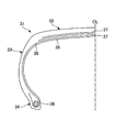
- FIG. 3 is a cross-sectional view of a tire according to one aspect of the present disclosure.
- FIG. 4 is a diagram schematically showing the belt layer.
- FIG. 5 is an explanatory diagram of the durability test in the experimental example.
- the steel wire used for the tire is also required to be a steel wire capable of forming a tire having excellent lightness and durability.
- a steel wire according to an aspect of the present disclosure has a flat shape in a cross section perpendicular to the longitudinal direction,
- the outer shape of the cross section is a first straight line portion, A second linear portion arranged so as to face the first linear portion, It has the 1st curved line part and the 2nd curved line part which connect between the 1st straight line part and the 2nd straight line part,
- the first curved portion and the second curved portion are arranged so as to face each other,
- the average value of the length of the first straight line portion and the length of the second straight line portion is W1
- When the maximum distance between the first curved portion and the second curved portion is W2
- the ratio of the W1 to the W2 is 75% or less.
- the steel wire can be placed on the belt layer of the tire, for example.
- the belt layer has a steel wire and rubber, and the steel wire is embedded in the rubber. Since the thickness of the belt layer can be selected so that the steel wire can be embedded in the rubber, the thickness of the belt layer can be suppressed by making the cross section of the steel wire a flat shape and suppressing the thickness. it can. Therefore, by using a steel wire having a flat cross-section, the amount of rubber contained in the belt layer can be suppressed as compared with the case where a circular steel wire having the same cross-sectional area is used, for example. Therefore, the weight of the belt layer can be reduced by using the steel wire having a flat cross section, and the tire including the belt layer can also be reduced in weight.
- the ratio of W1 to W2 can be 75% or less, the durability of the steel wire can be enhanced, and the durability of the tire using the steel wire is also improved. It was confirmed that it could be increased. This is because when the ratio of W1 to W2 is set to 75% or less, when processing the shape of the cross section of the steel wire into a flat shape, cracks occur at the boundary between the location subjected to compression processing and the location subjected to tensile processing. It is thought that this is because the occurrence of can be suppressed.
- the steel wire according to one aspect of the present disclosure it becomes possible to provide a steel wire that can form a tire excellent in lightweight and durability.
- the ratio of W1 to W2 may be 60% or more.
- the thickness may be 0.30 mm or more.
- the thickness may be 0.50 mm or less.
- It may have a brass plating film containing Cu and Zn.
- Cu copper and Zn means zinc.
- the brass plating film may further contain one or more elements selected from Co and Ni.
- Co cobalt
- Ni nickel
- a tire including the steel wire according to any one of (1) to (8) may be used.
- FIG. 1 shows a sectional view of the steel wire 10 of the present embodiment in a plane perpendicular to the longitudinal direction.
- the steel wire 10 of the present embodiment is one wire, that is, a single wire, and can also be called a single wire steel wire. Further, the steel wire 10 of the present embodiment is preferably not twisted along the longitudinal direction, and is preferably a straight steel wire.
- the steel wire 10 of the present embodiment can have a flat shape in a cross section perpendicular to the longitudinal direction.
- the flat shape here means that the thickness is shorter than the width and the shape is flat.
- a cross section perpendicular to the longitudinal direction of the steel wire is also simply referred to as a “cross section”.
- the steel wire can be placed on the belt layer of the tire, for example.
- the belt layer has a steel wire and rubber, which will be described later in the description of the tire, and the steel wire is embedded in the rubber. Since the thickness of the belt layer can be selected so that the steel wire can be embedded in the rubber, the thickness of the belt layer can be suppressed by making the cross section of the steel wire a flat shape and suppressing the thickness. it can. Therefore, by using a steel wire having a flat cross-section, the amount of rubber contained in the belt layer can be suppressed as compared with the case where a circular steel wire having the same cross-sectional area is used, for example. Therefore, the weight of the belt layer can be reduced by using the steel wire having a flat cross section, and the tire including the belt layer can also be reduced in weight.
- the durability of the steel wire may not be sufficient, for example, when repeatedly deformed by applying an external force, There was a case where it broke with a small number of deformations. Therefore, the inventors of the present invention further studied a steel wire that can achieve both weight reduction and durability of the tire when used for the tire. As a result, it has been found that by making the cross-sectional shape of the steel wire a predetermined flat shape, the durability of the steel wire can be increased, and the weight and durability of the tire using the steel wire can be increased.
- the outer shape of the cross section of the steel wire 10 according to the present embodiment includes a first straight line portion 11 and a second straight line portion 12 arranged so as to face the first straight line portion 11.
- the outer shape of the cross section of the steel wire 10 of the present embodiment has a first curved line portion 13 and a second curved line portion 14 that connect between the first straight line portion 11 and the second straight line portion 12.
- the first straight line portion 11 and the second straight line portion 12 are preferably parallel to each other as shown in FIG.
- the term “parallel” here does not mean parallel in a strict sense, but means that the two linear portions are arranged in parallel.
- first curved line portion 13 and the second curved line portion 14 are arranged so as to face each other.
- the first curved line portion 13 and the second curved line portion 14 may each be configured to connect between the end portion of the first straight line portion 11 and the end portion of the second straight line portion 12.
- the shape is not particularly limited.
- each of the first curved portion 13 and the second curved portion 14 may have a curved shape that is convex on the outside of the steel wire 10.
- the average value of the length W11 of the first straight line portion 11 and the length W12 of the second straight line portion 12 is set to W1
- the average value between the first curved line portion 13 and the second curved line portion 14 is set.
- the ratio of W1 to W2 is preferably 75% or less, and more preferably 72% or less.
- the above W2 means the distance between the first curved line portion 13 and the second curved line portion 14 at the longest portion, and can also be called the width of the steel wire 10.
- the length W11 of the first straight line portion 11, the length W12 of the second straight line portion 12, and the maximum distance W2 between the first curved line portion 13 and the second curved line portion 14 are the sectional shape of the steel wire. In order to avoid the influence of the variation, it is preferable that it is an average value of values measured in a plurality of cross sections perpendicular to the longitudinal direction of the steel wire.
- the length W11 of the first straight line portion 11, the length W12 of the second straight line portion 12, and the maximum distance W2 between the first curved line portion 13 and the second curved line portion 14 are, for example, the length of the steel wire. More preferably, it is an average value of the measured values in three cross sections perpendicular to the direction.
- the distance between adjacent cross sections is preferably 1 cm or more and 5 cm or less.
- a flat-shaped steel wire can be formed, for example, by rolling a steel wire having a circular cross-section.
- the above-described first straight line portion 11 and second straight line portion 12 are formed when rolling a steel wire having a circular cross-sectional shape.
- the average value W1 of the length W11 of the first straight line portion 11 and the length W12 of the second straight line portion 12 is increased, and the maximum distance W2 between the first curved line portion 13 and the second curved line portion 14 is increased.
- the durability of the steel wire can be improved, and the tire using the steel wire can be improved. It was confirmed that the durability can be improved. This is because when the ratio of W1 to W2 is set to 75% or less, when processing the shape of the cross section of the steel wire into a flat shape, cracks occur at the boundary between the location subjected to compression processing and the location subjected to tensile processing. It is thought that this is because the occurrence of can be suppressed.
- the lower limit of the ratio of W1 to W2 is not particularly limited, but is preferably 60% or more, and more preferably 62% or more.
- the concrete size of W1 which is the average value of the length W11 of the first straight line portion 11 and the length W12 of the second straight line portion 12 of the steel wire of the present embodiment is not particularly limited, and may be, for example, a flat shape. It can be arbitrarily selected according to the size of the steel wire before being processed into. W1 is preferably, for example, 0.25 mm or more and 0.36 mm or less, and more preferably 0.27 mm or more and 0.36 mm or less.
- the maximum distance W2 between the first curved portion 13 and the second curved portion 14 of the steel wire 10 of the present embodiment is also particularly Not limited.
- the maximum distance W2 between the first curved portion 13 and the second curved portion 14 of the steel wire 10 of this embodiment is preferably 0.42 mm or more and 0.52 mm or less, and 0.43 mm, for example. More preferably, it is 0.50 mm or less.
- the flatness of the steel wire 10 of the present embodiment is not particularly limited, but the flatness is preferably 60% or more.
- the thickness T is also preferably an average value of values measured in a plurality of cross sections perpendicular to the longitudinal direction of the steel wire, as in the case of W11, W12, and W2 described above.
- the thickness T is more preferably an average value of measured values in three cross sections perpendicular to the longitudinal direction of the steel wire.
- the distance between adjacent cross sections is 1 cm or more and 5 cm or less, depending on the length of the test piece of the steel wire. Is preferred.
- the durability of the steel wire can be particularly enhanced by setting the flatness to 60% or more.
- the flatness is more preferably 63% or more.
- the upper limit of the flatness is not particularly limited, but it is preferably 80% or less, more preferably 75% or less.
- the flatness of 80% or less is preferable because the thickness of the steel wire can be particularly suppressed, and the thickness of the belt layer can be particularly suppressed when used in a tire.
- the flatness rate is set to 80% or less, residual stress due to the processing difference between the thickness direction and the width direction of the steel wire and the line habit due to the spiral shape (helical shape) due to the difference in surface hardness This is because the occurrence can be particularly suppressed and the handleability is excellent, so that the productivity can be increased when used in a tire or the like.
- the thickness of the steel wire of this embodiment is not particularly limited, but is preferably 0.30 mm or more, more preferably 0.32 mm or more.
- the durability of the steel wire can be particularly enhanced by setting the thickness T of the steel wire to 0.30 mm or more.
- the upper limit of the thickness T of the steel wire is not particularly limited, but is preferably 0.50 mm or less, and more preferably 0.42 mm or less. This is because the thickness T of the steel wire is set to 0.50 mm or less, so that when the steel wire is used for a tire, the thickness of the belt layer on which the steel wire is arranged, and further the rubber contained in the belt layer The amount can be suppressed. Therefore, the belt layer using the steel wire and the tire including the belt layer can be reduced in weight.
- the thickness T of the steel wire is the maximum distance between the first straight line portion 11 and the second straight line portion 12 as described above.
- the material of the steel wire of the present embodiment is not particularly limited, but the steel wire of the present embodiment has a structure in which a steel wire 101 and a plating film 102 are arranged on the surface of the steel wire 101 as shown in FIG. 1, for example. Can have.
- High-carbon steel wire can be preferably used as the steel wire.
- the plating film may be, for example, a plating film in which the metal components are only Cu (copper) and Zn (zinc), that is, a brass plating film, but further contains Cu and a metal component other than Zn. You can also do it.
- the plating film may further contain, for example, one or more kinds of elements selected from Co (cobalt) and Ni (nickel) as metal components.
- the steel wire of the present embodiment can have a brass plating film containing Cu and Zn, for example.
- the brass plating film may further contain one or more kinds of elements selected from Co and Ni.
- the brass plating film can be arranged on the surface of the steel wire, for example, as described above.
- the steel wire of the present embodiment has the brass plating film containing Cu and Zn, when the steel wire is covered with rubber to form a tire, the adhesive force between the steel wire and the rubber is increased, and particularly the durability is improved.
- the tire can be excellent.
- the brass plating film further contains one or more kinds of elements selected from Co and Ni, the adhesive force between the steel wire and the rubber can be further enhanced, and the durability of the tire can be further enhanced. preferable.
- the method for manufacturing the steel wire according to the present embodiment is not particularly limited, and the steel wire can be manufactured so that the cross-sectional shape thereof is the shape described above.
- the method for manufacturing a steel wire according to this embodiment can include the following steps, for example.
- An unprocessed steel wire preparation step in which an unprocessed steel wire having a circular cross section perpendicular to the longitudinal direction is prepared.
- a first rolling step in which a pre-working steel wire is supplied to a pair of first rolling rollers whose pressing surfaces face each other and is pressed along a first axial direction parallel to a diameter in a cross section perpendicular to the longitudinal direction of the pre-working steel wire. ..
- the unprocessed steel wire after the first rolling step is supplied between the pair of second rolling rollers whose pressure surfaces face each other, and is orthogonal to the first axial direction in a cross section perpendicular to the longitudinal direction of the unprocessed steel wire.
- a second rolling process in which pressure is applied along the biaxial direction.
- the 1st rolling process and the 2nd rolling process can be implemented by rolling device 20 shown in Drawing 2, for example.
- the rolling apparatus 20 has a pair of first rolling rollers 221, 222 whose pressing surfaces are opposed to each other, and the pair of first rolling rollers 221, 222 has the unprocessed steel wire 21 and the cross section of the unprocessed steel wire 21.
- the pressure can be applied along the first axis direction parallel to the diameter at, for example, the thickness direction.
- the first axis direction corresponds to the Z axis direction
- the pair of first rolling rollers 221 and 222 move the unprocessed steel wire 21 along the Z axis direction in FIG.
- the first rolling step can be performed by applying pressure from the vertical direction.
- the unprocessed steel wire 21 is pressed and rolled by the pair of first rolling rollers 221, 222, so that the first straight portion 11 of the cross section of the steel wire 10 shown in FIG.
- the second straight portion 12 can be formed. Therefore, the pair of first rolling rollers 221, 222 include flat portions corresponding to the first straight line portion 11 and the second straight line portion 12 on their respective pressing surfaces, that is, the surfaces in contact with the unprocessed steel wire 21. Preferably.
- the rolling device 20 may have a pair of second rolling rollers 231 and 232 on the downstream side of the pair of first rolling rollers 221 and 222 in the transport direction of the unprocessed steel wire 21.
- the pair of second rolling rollers 231, 232 forms the unprocessed steel wire 21 after the first rolling step along the second axial direction orthogonal to the first axial direction in the cross section of the unprocessed steel wire 21, for example, along the width direction. Can be pressurized.
- the second axial direction corresponds to the X-axis direction
- the pair of second rolling rollers 231 and 232 is the unprocessed steel wire 21 after the first rolling step, which is shown in FIG.
- the second rolling step can be carried out by applying pressure from the left and right directions along the X-axis direction.
- orthogonality does not mean an orthogonality in a strict sense, but may be substantially orthogonal including a certain amount of error.
- the unprocessed steel wire 21 after the first rolling step is pressed and rolled by the pair of second rolling rollers 231 and 232, so that the first section of the steel wire 10 shown in FIG.
- the curved portion 13 and the second curved portion 14 can be formed.
- the pair of second rolling rollers 231, 232 have respective pressing surfaces, that is, the surfaces in contact with the unprocessed steel wire 21, that have shapes corresponding to the first curved portion 13 and the second curved portion 14.
- the second rolling rollers 231, 232 are, for example, grooves whose cross-sectional shape in a plane passing through the central axes of the second rolling rollers 231, 232 has a shape corresponding to the first curved portion 13 and the second curved portion 14. 231A and 232A, respectively.
- first rolling step and the second rolling step it is possible to adjust the pressure, the degree of rolling, etc. so as to satisfy the cross-sectional shape of the steel wire of the present embodiment described above.
- the unprocessed steel wire 21 is conveyed along the arrow A in FIG. 2, that is, along the Y-axis direction, and the first rolling step and the second rolling step are performed with respect to the entire longitudinal direction thereof.
- the steel wire of this embodiment can be manufactured by carrying out.
- the configuration example of the method for manufacturing the steel wire of the present embodiment has been described by taking the case of performing the first rolling step and the second rolling step as an example, but the present invention is not limited to such a configuration.
- the shape of the cross section can be changed to the shape described above by only the first rolling step, the second rolling step need not be performed.
- the tire of this embodiment may include the steel wire described above.
- FIG. 3 shows a cross-sectional view of the tire 31 according to the present embodiment in a plane perpendicular to the circumferential direction.
- FIG. 3 shows only a portion on the left side of CL (center line), CL has the same structure continuously on the right side of CL with the axis of symmetry being CL.
- the tire 31 includes a tread portion 32, a sidewall portion 33, and a bead portion 34.
- the tread portion 32 is a portion in contact with the road surface.
- the bead portion 34 is provided on the inner diameter side of the tire 31 with respect to the tread portion 32.
- the bead portion 34 is a portion that contacts the rim of the vehicle wheel.
- the sidewall portion 33 connects the tread portion 32 and the bead portion 34. When the tread portion 32 receives an impact from the road surface, the sidewall portion 33 elastically deforms and absorbs the impact.
- the tire 31 includes an inner liner 35, a carcass 36, a belt layer 37, and a bead wire 38.
- the inner liner 35 is made of rubber and seals the space between the tire 31 and the wheel.
- the carcass 36 forms the skeleton of the tire 31.
- the carcass 36 is composed of an organic fiber such as polyester, nylon or rayon or a steel wire, and rubber.
- the bead wire 38 is provided on the bead portion 34.
- the bead wire 38 receives the pulling force acting on the carcass.
- the belt layer 37 tightens the carcass 36 to increase the rigidity of the tread portion 32.
- the tire 31 has two belt layers 37.
- FIG. 4 is a diagram schematically showing the two belt layers 37.
- FIG. 4 is a cross-sectional view taken along a plane perpendicular to the longitudinal direction of the belt layer 37, that is, the circumferential direction of the tire 31.
- each belt layer 37 has a plurality of steel wires 41 and rubber 42.
- the plurality of steel wires 41 are arranged in parallel in a row.
- the steel wire 41 the above-mentioned steel wire can be used.
- the above-mentioned steel wire has a flat shape in a cross section perpendicular to the longitudinal direction, and it is preferable to arrange the steel wire so that the thickness direction of the steel wire matches the thickness direction of the belt layer. Therefore, for example, it is preferable to arrange the steel wire 10 so that the first straight line portion 11 and the second straight line portion 12 of the steel wire 10 described above extend along the width direction of the belt layer.
- the rubber 42 covers the steel wire 41, and the entire circumference of each steel wire 41 is covered with the rubber 42.
- the steel wire 41 is embedded in the rubber 42.
- the steel wire described above has a flat shape in a cross section perpendicular to the longitudinal direction. Therefore, in the belt layer 37, the first rubber thickness t1 that is the thickness of the rubber 42 that is arranged below the steel wire 41 and the second rubber thickness that is the thickness of the rubber 42 that is arranged above the steel wire 41. Even if t2 is made thin, the steel wire 41 can be prevented from being exposed. Therefore, the overall thickness of the belt layer 37 can be reduced.
- the overall thickness of the belt layer 37 including the steel wire 41 described above can be suppressed, and the belt layer 37 can be reduced in thickness. It is possible to reduce the weight. Therefore, it is possible to reduce the weight of the tire of the present embodiment including the belt layer, and suppress the rolling resistance of the tire.
- the steel wire described above has excellent durability. Therefore, the durability of the tire of this embodiment using the steel wire can be improved.
- the length and distance of each part were measured in three sections, and the average of the measured values of the length and distance in each of the three sections was taken as the length and distance of each part of the steel wire.
- the positions of the three cross sections subjected to the measurement were set so that the distance between adjacent cross sections was 5 cm.
- the length W11 of the first straight line portion 11 and the length W12 of the second straight line portion 12 in each of the three cross sections are measured, and the average value is W11 of the steel wire 10 of each experimental example. It was set to W12. Further, the average value W1 of W11 and W12 was calculated.
- the thickness T which is the maximum distance between the first straight line portion 11 and the second straight line portion 12 in the three cross sections, was measured, and the average value was used as the thickness T of the steel wire 10 of each experimental example.
- the maximum distance W2 between the first curved portion 13 and the second curved portion 14 in three sections, that is, the width of the steel wire 10 was measured, and the average value was taken as the width of the steel wire 10 of each experimental example. ..
- a cord-shaped test piece having a cross-sectional shape including a steel wire of 5 mm in thickness and 10 mm in width was taken out from the obtained steel wire/rubber composite with a cutter knife.
- the obtained test piece 50 was applied to a first roller 511, a second roller 512, and a third roller 513 each having a roller diameter of 25 mm.
- the test piece 50 located between the first roller 511 and the second roller 512 and the test piece 50 located between the second roller 512 and the third roller 513.
- the position of each roller was adjusted so that and were parallel.
- a load of 29.4 N is applied along the longitudinal direction of the test piece 50 applied to the first roller 511 to the third roller 513.
- the first roller 511 to the third roller 513 are rotated, the test piece 50 is moved in the direction of arrow B in FIG. 5, and then the first roller 511 to the third roller 513 are reversely rotated.
- the rubber composition is based on natural rubber as a rubber component and contains carbon black, sulfur, zinc oxide, cobalt organic acid and cobalt stearate as additives.
- a rubber sheet having the same structure as the belt layer 37 shown in FIG. 4 was produced using the steel wire and the rubber composition produced in each experimental example.
- the weight of the rubber sheet prepared by using the steel wire having a circular cross section and a wire diameter of 0.415 mm prepared as a steel wire before processing in each of the following experimental examples is set to 100, and the steel wire of each experimental example is set.
- the weight of the rubber sheet produced by using is represented by an index.
- Experimental Examples 1 to 5 are Examples, and Experimental Examples 6 and 7 are Comparative Examples.
- the unprocessed steel wire 21 has a structure in which a brass plating film having metal components Cu and Zn is arranged on the surface of a high carbon steel wire.
- the unprocessed steel wire was supplied to the rolling apparatus 20 shown in FIG. 2 and processed so as to have the predetermined cross-sectional shape shown in FIG.
- the rolling device 20 has the pair of first rolling rollers 221 and 222 whose pressing surfaces face each other, and the unprocessed steel wire 21 is supplied between the pair of first rolling rollers 221 and 222. Then, the pair of first rolling rollers 221, 222 presses the unprocessed steel wire 21 from above and below along the Z-axis direction in FIG. 2, that is, along the thickness direction of the unprocessed steel wire 21. (1st rolling process). As the pair of first rolling rollers 221, 222, those having flat portions corresponding to the first straight line portion 11 and the second straight line portion 12 to be formed on their respective pressing surfaces were used.
- a pair of second rolling rollers 231 and 232 is arranged on the downstream side of the pair of first rolling rollers 221 and 222 in the transport direction of the unprocessed steel wire 21, and after the first rolling step.
- the unprocessed steel wire 21 was supplied between the pair of second rolling rollers 231 and 232.
- the pair of second rolling rollers 231, 232 causes the unprocessed steel wire 21 after the first rolling step to move along the X-axis direction in FIG. 2, that is, along the width direction of the unprocessed steel wire 21. Pressure was applied from the left and right (second rolling step). It should be noted that the pair of second rolling rollers 231, 232 have, on their respective pressing surfaces, a cross-sectional shape in a plane passing through the central axes of the second rolling rollers 231, 232 having a first curved portion 13 and a second curved portion. Those having grooves 231A and 232A having a shape corresponding to the portion 14 were used.
- the unprocessed steel wire 21 is conveyed along the arrow A in FIG. 2, and the first rolling step and the second rolling step described above are performed for the entire longitudinal direction thereof, and the present experimental example Manufactured steel wire.
- the degree of pressurization and rolling was adjusted so that the thickness T of the steel wire was 0.34 mm, W1 was 0.28 mm, and W2 was 0.44 mm.
- Table 1 shows the evaluation results.
Landscapes
- Engineering & Computer Science (AREA)
- Mechanical Engineering (AREA)
- Tires In General (AREA)
- Ropes Or Cables (AREA)
Abstract
Description
前記断面の外形が、第1の直線部と、
前記第1の直線部と対向するように配置された第2の直線部と、
前記第1の直線部と、前記第2の直線部との間を接続する第1の曲線部及び第2の曲線部とを有しており、
前記第1の曲線部と、前記第2の曲線部とは対向するように配置され、
前記第1の直線部の長さと、前記第2の直線部の長さとの平均値をW1、
前記第1の曲線部と、前記第2の曲線部との間の最大距離をW2とした場合に、
前記W2に対する前記W1の割合が75%以下である。
特許文献1に開示された発明によれば、サイド補強層の補強線材として、複数本のフィラメントを撚り合わせてなるスチールコードの替りに単線スチールワイヤーを使用することで、コートゴムの使用量を減らして空気入りラジアルタイヤの転がり抵抗を低減できるとされている。
[本開示の効果]
本開示によれば、軽量性、及び耐久性に優れたタイヤを形成することができるスチールワイヤーを提供できる。
最初に本開示の実施態様を列記して説明する。以下の説明では、同一または対応する要素には同一の符号を付し、それらについて同じ説明は繰り返さない。
前記断面の外形が、第1の直線部と、
前記第1の直線部と対向するように配置された第2の直線部と、
前記第1の直線部と、前記第2の直線部との間を接続する第1の曲線部及び第2の曲線部とを有しており、
前記第1の曲線部と、前記第2の曲線部とは対向するように配置され、
前記第1の直線部の長さと、前記第2の直線部の長さとの平均値をW1、
前記第1の曲線部と、前記第2の曲線部との間の最大距離をW2とした場合に、
前記W2に対する前記W1の割合が75%以下である。
前記厚さが0.50mm以下であってもよい。
本開示の一実施形態(以下「本実施形態」と記す)に係るスチールワイヤー、タイヤの具体例を、以下に図面を参照しつつ説明する。なお、本発明はこれらの例示に限定されるものではなく、特許の請求の範囲によって示され、請求の範囲と均等の意味及び範囲内での全ての変更が含まれることが意図される。
以下、本実施形態に係るスチールワイヤーについて図1に基づき説明する。
加圧面が対向する一対の第1圧延ローラーに、加工前スチールワイヤーを供給し、加工前スチールワイヤーの長手方向と垂直な断面における直径と平行な第1軸方向に沿って加圧する第1圧延工程。
加圧面が対向する一対の第2圧延ローラー間に、第1圧延工程後の加工前スチールワイヤーを供給し、加工前スチールワイヤーの長手方向と垂直な断面における、上記第1軸方向と直交する第2軸方向に沿って加圧する第2圧延工程。
第1圧延工程と、第2圧延工程とは、例えば図2に示した圧延装置20により実施することができる。
次に、本実施形態におけるタイヤについて図3、図4に基き説明する。
このように、本実施形態のタイヤによれば、既述のスチールワイヤー41を含むベルト層37全体の厚さを抑制することができ、ベルト層37を軽量化することが可能になる。このため、係るベルト層を含む本実施形態のタイヤについても軽量化することができ、タイヤの転がり抵抗を抑制できる。
(評価方法)
まず、以下の実験例において作製したスチールワイヤーの評価方法について説明する。
(1)スチールワイヤーの断面形状の評価
得られたスチールワイヤーを透明樹脂に埋め込み、スチールワイヤーの長手方向と垂直な面(断面)が露出するように試料を切り出した。
(W2に対するW1の割合(%))=W1/W2×100
また、測定、算出した厚さTと、第1の曲線部13と、第2の曲線部14との間の最大距離W2である幅とから、以下の式により扁平率を算出した。
(2)耐久性試験
以下の各実験例で作製したスチールワイヤーを、ゴムシートの上に配置し、さらにその上からゴムシートを被せた。これにより、トータル厚さがスチールワイヤーの厚さの5倍である、直方体形状を有するゴムシートと、スチールワイヤーとの積層物を用意した。そして、係るゴムシートと、スチールワイヤーとの積層物について160℃、20分の条件で加硫した。
(3)重量指数
重量指数の評価に当たって、以下の各実験例で作製したスチールワイヤーを用いてゴムシートを作製した。
(実験例)
以下、実験条件について説明する。実験例1~実験例5が実施例、実験例6、7が比較例となる。
[実験例1]
ワイヤー径が0.415mmの、断面の形状が円形状である加工前スチールワイヤー21を用意した(加工前スチールワイヤー準備工程)。なお、加工前スチールワイヤー21は、高炭素鋼線の表面に、金属成分がCuとZnとからなるブラスめっき膜が配置された構成を有している。
[実験例2~実験例7]
第1圧延工程、第2圧延工程において、厚さT、W1、W2が表1に示した値となるようにその加圧、圧延の程度を調整した点以外は、実験例1と同様にしてスチールワイヤーを製造し、その評価を行った。

101 鋼線
102 めっき膜
11 第1の直線部
12 第2の直線部
13 第1の曲線部
14 第2の曲線部
T 厚さ
W11 第1の直線部の長さ
W12 第2の直線部の長さ
W2 第1の曲線部と、第2の曲線部との間の最大距離
20 圧延装置
21 加工前スチールワイヤー
221、222 第1圧延ローラー
231、232 第2圧延ローラー
231A、232A 溝
31 タイヤ
32 トレッド部
33 サイドウォール部
34 ビード部
35 インナーライナー
36 カーカス
37 ベルト層
38 ビードワイヤー
41 スチールワイヤー
42 ゴム
t1 第1ゴム厚さ
t2 第2ゴム厚さ
50 試験片
511 第1のローラー
512 第2のローラー
513 第3のローラー
Claims (9)
- 長手方向と垂直な断面が扁平形状を有し、
前記断面の外形が、第1の直線部と、
前記第1の直線部と対向するように配置された第2の直線部と、
前記第1の直線部と、前記第2の直線部との間を接続する第1の曲線部及び第2の曲線部とを有しており、
前記第1の曲線部と、前記第2の曲線部とは対向するように配置され、
前記第1の直線部の長さと、前記第2の直線部の長さとの平均値をW1、
前記第1の曲線部と、前記第2の曲線部との間の最大距離をW2とした場合に、
前記W2に対する前記W1の割合が75%以下であるスチールワイヤー。 - 前記W2に対する前記W1の割合が60%以上である請求項1に記載のスチールワイヤー。
- 前記第1の直線部と、前記第2の直線部との間の最大距離を厚さとした場合に、
前記厚さの前記W2に対する割合である扁平率が60%以上である請求項1または請求項2に記載のスチールワイヤー。 - 前記第1の直線部と、前記第2の直線部との間の最大距離を厚さとした場合に、
前記厚さの前記W2に対する割合である扁平率が80%以下である請求項1から請求項3のいずれか1項に記載のスチールワイヤー。 - 前記第1の直線部と、前記第2の直線部との間の最大距離を厚さとした場合に、
前記厚さが0.30mm以上である請求項1から請求項4のいずれか1項に記載のスチールワイヤー。 - 前記第1の直線部と、前記第2の直線部との間の最大距離を厚さとした場合に、
前記厚さが0.50mm以下である請求項1から請求項5のいずれか1項に記載のスチールワイヤー。 - Cu及びZnを含むブラスめっき膜を有する請求項1~請求項6のいずれか1項に記載のスチールワイヤー。
- 前記ブラスめっき膜は、さらにCo、及びNiから選択された1種類以上の元素を含有する請求項7に記載のスチールワイヤー。
- 請求項1~請求項8のいずれか1項に記載のスチールワイヤーを含むタイヤ。
Priority Applications (5)
| Application Number | Priority Date | Filing Date | Title |
|---|---|---|---|
| BR112021010441-0A BR112021010441A2 (pt) | 2018-12-06 | 2019-10-24 | Fio de aço e pneu |
| DE112019006073.2T DE112019006073T5 (de) | 2018-12-06 | 2019-10-24 | Stahldraht und Reifen |
| JP2020559781A JPWO2020116047A1 (ja) | 2018-12-06 | 2019-10-24 | スチールワイヤー、タイヤ |
| US17/294,001 US20220001696A1 (en) | 2018-12-06 | 2019-10-24 | Steel wire and tire |
| CN201980078701.8A CN113167025A (zh) | 2018-12-06 | 2019-10-24 | 钢丝和轮胎 |
Applications Claiming Priority (2)
| Application Number | Priority Date | Filing Date | Title |
|---|---|---|---|
| JP2018229035 | 2018-12-06 | ||
| JP2018-229035 | 2018-12-06 |
Publications (1)
| Publication Number | Publication Date |
|---|---|
| WO2020116047A1 true WO2020116047A1 (ja) | 2020-06-11 |
Family
ID=70973583
Family Applications (1)
| Application Number | Title | Priority Date | Filing Date |
|---|---|---|---|
| PCT/JP2019/041742 Ceased WO2020116047A1 (ja) | 2018-12-06 | 2019-10-24 | スチールワイヤー、タイヤ |
Country Status (6)
| Country | Link |
|---|---|
| US (1) | US20220001696A1 (ja) |
| JP (1) | JPWO2020116047A1 (ja) |
| CN (1) | CN113167025A (ja) |
| BR (1) | BR112021010441A2 (ja) |
| DE (1) | DE112019006073T5 (ja) |
| WO (1) | WO2020116047A1 (ja) |
Cited By (4)
| Publication number | Priority date | Publication date | Assignee | Title |
|---|---|---|---|---|
| JPWO2022085230A1 (ja) * | 2020-10-19 | 2022-04-28 | ||
| US20230158835A1 (en) * | 2019-12-25 | 2023-05-25 | Sumitomo Rubber Industries, Ltd. | Tire and belt layer |
| CN116964269A (zh) * | 2021-06-14 | 2023-10-27 | 住友电气工业株式会社 | 复合片和钢丝 |
| WO2025047070A1 (ja) * | 2023-08-29 | 2025-03-06 | 住友電気工業株式会社 | スチールコード、タイヤ |
Citations (3)
| Publication number | Priority date | Publication date | Assignee | Title |
|---|---|---|---|---|
| JP2006336154A (ja) * | 2005-06-02 | 2006-12-14 | Tokyo Seiko Co Ltd | ゴム補強用偏平ワイヤ |
| JP2012219419A (ja) * | 2011-04-13 | 2012-11-12 | Bridgestone Corp | ゴム物品補強用ワイヤ及びその製造方法 |
| DE102015209343A1 (de) * | 2015-05-21 | 2016-11-24 | Continental Reifen Deutschland Gmbh | Fahrzeugluftreifen |
Family Cites Families (5)
| Publication number | Priority date | Publication date | Assignee | Title |
|---|---|---|---|---|
| WO1997049776A1 (en) * | 1996-06-26 | 1997-12-31 | Bridgestone Corporation | Adhesion accelerator compositions and adhesive rubber composition |
| WO2000071809A1 (fr) * | 1999-05-24 | 2000-11-30 | Tokyo Rope Mfg. Co., Ltd. | Cable d'acier unifilaire et procede de production de celui-ci |
| KR100318895B1 (ko) * | 1999-12-24 | 2001-12-29 | 최의박 | 고무 침투성이 우수한 고무 보강재용 스틸코드 |
| CN103597138B (zh) * | 2011-06-10 | 2016-02-03 | 贝卡尔特公司 | 包括扁平钢丝的钢丝帘线 |
| WO2015105139A1 (ja) * | 2014-01-09 | 2015-07-16 | 新日鐵住金株式会社 | 樹脂被覆高張力平型鋼線及びその製造方法 |
-
2019
- 2019-10-24 CN CN201980078701.8A patent/CN113167025A/zh active Pending
- 2019-10-24 DE DE112019006073.2T patent/DE112019006073T5/de not_active Ceased
- 2019-10-24 JP JP2020559781A patent/JPWO2020116047A1/ja active Pending
- 2019-10-24 US US17/294,001 patent/US20220001696A1/en not_active Abandoned
- 2019-10-24 WO PCT/JP2019/041742 patent/WO2020116047A1/ja not_active Ceased
- 2019-10-24 BR BR112021010441-0A patent/BR112021010441A2/pt not_active Application Discontinuation
Patent Citations (3)
| Publication number | Priority date | Publication date | Assignee | Title |
|---|---|---|---|---|
| JP2006336154A (ja) * | 2005-06-02 | 2006-12-14 | Tokyo Seiko Co Ltd | ゴム補強用偏平ワイヤ |
| JP2012219419A (ja) * | 2011-04-13 | 2012-11-12 | Bridgestone Corp | ゴム物品補強用ワイヤ及びその製造方法 |
| DE102015209343A1 (de) * | 2015-05-21 | 2016-11-24 | Continental Reifen Deutschland Gmbh | Fahrzeugluftreifen |
Cited By (10)
| Publication number | Priority date | Publication date | Assignee | Title |
|---|---|---|---|---|
| US20230158835A1 (en) * | 2019-12-25 | 2023-05-25 | Sumitomo Rubber Industries, Ltd. | Tire and belt layer |
| JPWO2022085230A1 (ja) * | 2020-10-19 | 2022-04-28 | ||
| WO2022085230A1 (ja) * | 2020-10-19 | 2022-04-28 | 住友電気工業株式会社 | スチールワイヤー、タイヤ |
| WO2022085052A1 (ja) * | 2020-10-19 | 2022-04-28 | 住友電気工業株式会社 | スチールワイヤー、タイヤ |
| CN116194308A (zh) * | 2020-10-19 | 2023-05-30 | 住友电气工业株式会社 | 钢丝和轮胎 |
| US12209362B2 (en) | 2020-10-19 | 2025-01-28 | Sumitomo Electric Industries, Ltd. | Steel wire and tire |
| JP7704149B2 (ja) | 2020-10-19 | 2025-07-08 | 住友電気工業株式会社 | スチールワイヤー、タイヤ |
| CN116194308B (zh) * | 2020-10-19 | 2025-12-23 | 住友电气工业株式会社 | 钢丝和轮胎 |
| CN116964269A (zh) * | 2021-06-14 | 2023-10-27 | 住友电气工业株式会社 | 复合片和钢丝 |
| WO2025047070A1 (ja) * | 2023-08-29 | 2025-03-06 | 住友電気工業株式会社 | スチールコード、タイヤ |
Also Published As
| Publication number | Publication date |
|---|---|
| DE112019006073T5 (de) | 2021-08-26 |
| JPWO2020116047A1 (ja) | 2021-10-14 |
| BR112021010441A2 (pt) | 2021-08-24 |
| US20220001696A1 (en) | 2022-01-06 |
| CN113167025A (zh) | 2021-07-23 |
Similar Documents
| Publication | Publication Date | Title |
|---|---|---|
| JP5883898B2 (ja) | タイヤ補強用スチールコードおよびこれを適用したラジアルタイヤ | |
| WO2020116047A1 (ja) | スチールワイヤー、タイヤ | |
| KR20160023836A (ko) | 스트립 형상 스틸 코드 | |
| US20120193006A1 (en) | Pneumatic tire | |
| JP7704149B2 (ja) | スチールワイヤー、タイヤ | |
| JP4608270B2 (ja) | 空気入りタイヤ | |
| JPWO2013176082A1 (ja) | 乗用車用空気入りラジアルタイヤ | |
| CN105121182B (zh) | 充气轮胎 | |
| JP2021120266A (ja) | コード・ゴム複合体及び空気入りタイヤ | |
| WO2020080439A1 (ja) | タイヤ | |
| EP3106321B1 (en) | Pneumatic tire | |
| JP7548561B2 (ja) | ベルト、タイヤ | |
| EP3770319B1 (en) | Steel cord and tire | |
| JP5718070B2 (ja) | 空気入りタイヤ | |
| JP5602609B2 (ja) | ゴム物品補強用スチールコードおよびそれを用いた空気入りタイヤ | |
| EP3090885B1 (en) | Pneumatic tire | |
| JP5947496B2 (ja) | 空気入りラジアルタイヤ | |
| CN112839827B (zh) | 弹性体-金属帘线复合体和使用该复合体的轮胎 | |
| JP5746900B2 (ja) | ゴム物品補強用ワイヤ及びその製造方法 | |
| JP5718085B2 (ja) | 空気入りタイヤ | |
| JPH1088488A (ja) | ゴム補強用スチールコードおよびラジアルタイヤ | |
| JPH061108A (ja) | 空気入りラジアルタイヤ | |
| JP7419644B2 (ja) | ベルト積層体、タイヤ | |
| JP6574683B2 (ja) | 空気入りタイヤ | |
| JP4904912B2 (ja) | ゴム補強用スチールコード及びそれを用いた空気入りラジアルタイヤ |
Legal Events
| Date | Code | Title | Description |
|---|---|---|---|
| 121 | Ep: the epo has been informed by wipo that ep was designated in this application |
Ref document number: 19894044 Country of ref document: EP Kind code of ref document: A1 |
|
| ENP | Entry into the national phase |
Ref document number: 2020559781 Country of ref document: JP Kind code of ref document: A |
|
| WWE | Wipo information: entry into national phase |
Ref document number: 2101003114 Country of ref document: TH |
|
| REG | Reference to national code |
Ref country code: BR Ref legal event code: B01A Ref document number: 112021010441 Country of ref document: BR |
|
| ENP | Entry into the national phase |
Ref document number: 112021010441 Country of ref document: BR Kind code of ref document: A2 Effective date: 20210528 |
|
| 122 | Ep: pct application non-entry in european phase |
Ref document number: 19894044 Country of ref document: EP Kind code of ref document: A1 |