WO2020111246A1 - 丸鋼材の欠陥研削方法および鋼材の製造方法 - Google Patents
丸鋼材の欠陥研削方法および鋼材の製造方法 Download PDFInfo
- Publication number
- WO2020111246A1 WO2020111246A1 PCT/JP2019/046840 JP2019046840W WO2020111246A1 WO 2020111246 A1 WO2020111246 A1 WO 2020111246A1 JP 2019046840 W JP2019046840 W JP 2019046840W WO 2020111246 A1 WO2020111246 A1 WO 2020111246A1
- Authority
- WO
- WIPO (PCT)
- Prior art keywords
- round steel
- grinding
- marking
- steel material
- defect
- Prior art date
- Legal status (The legal status is an assumption and is not a legal conclusion. Google has not performed a legal analysis and makes no representation as to the accuracy of the status listed.)
- Ceased
Links
Images








Classifications
-
- B—PERFORMING OPERATIONS; TRANSPORTING
- B21—MECHANICAL METAL-WORKING WITHOUT ESSENTIALLY REMOVING MATERIAL; PUNCHING METAL
- B21B—ROLLING OF METAL
- B21B38/00—Methods or devices for measuring, detecting or monitoring specially adapted for metal-rolling mills, e.g. position detection, inspection of the product
-
- B—PERFORMING OPERATIONS; TRANSPORTING
- B21—MECHANICAL METAL-WORKING WITHOUT ESSENTIALLY REMOVING MATERIAL; PUNCHING METAL
- B21C—MANUFACTURE OF METAL SHEETS, WIRE, RODS, TUBES, PROFILES OR LIKE SEMI-MANUFACTURED PRODUCTS OTHERWISE THAN BY ROLLING; AUXILIARY OPERATIONS USED IN CONNECTION WITH METAL-WORKING WITHOUT ESSENTIALLY REMOVING MATERIAL
- B21C37/00—Manufacture of metal sheets, rods, wire, tubes, profiles or like semi-manufactured products, not otherwise provided for; Manufacture of tubes of special shape
- B21C37/04—Manufacture of metal sheets, rods, wire, tubes, profiles or like semi-manufactured products, not otherwise provided for; Manufacture of tubes of special shape of rods or wire
-
- B—PERFORMING OPERATIONS; TRANSPORTING
- B21—MECHANICAL METAL-WORKING WITHOUT ESSENTIALLY REMOVING MATERIAL; PUNCHING METAL
- B21C—MANUFACTURE OF METAL SHEETS, WIRE, RODS, TUBES, PROFILES OR LIKE SEMI-MANUFACTURED PRODUCTS OTHERWISE THAN BY ROLLING; AUXILIARY OPERATIONS USED IN CONNECTION WITH METAL-WORKING WITHOUT ESSENTIALLY REMOVING MATERIAL
- B21C51/00—Measuring, gauging, indicating, counting, or marking devices specially adapted for use in the production or manipulation of material in accordance with subclasses B21B - B21F
-
- B—PERFORMING OPERATIONS; TRANSPORTING
- B23—MACHINE TOOLS; METAL-WORKING NOT OTHERWISE PROVIDED FOR
- B23Q—DETAILS, COMPONENTS, OR ACCESSORIES FOR MACHINE TOOLS, e.g. ARRANGEMENTS FOR COPYING OR CONTROLLING; MACHINE TOOLS IN GENERAL CHARACTERISED BY THE CONSTRUCTION OF PARTICULAR DETAILS OR COMPONENTS; COMBINATIONS OR ASSOCIATIONS OF METAL-WORKING MACHINES, NOT DIRECTED TO A PARTICULAR RESULT
- B23Q17/00—Arrangements for observing, indicating or measuring on machine tools
- B23Q17/24—Arrangements for observing, indicating or measuring on machine tools using optics or electromagnetic waves
-
- B—PERFORMING OPERATIONS; TRANSPORTING
- B24—GRINDING; POLISHING
- B24B—MACHINES, DEVICES, OR PROCESSES FOR GRINDING OR POLISHING; DRESSING OR CONDITIONING OF ABRADING SURFACES; FEEDING OF GRINDING, POLISHING, OR LAPPING AGENTS
- B24B27/00—Other grinding machines or devices
- B24B27/033—Other grinding machines or devices for grinding a surface for cleaning purposes, e.g. for descaling or for grinding off flaws in the surface
-
- G—PHYSICS
- G01—MEASURING; TESTING
- G01B—MEASURING LENGTH, THICKNESS OR SIMILAR LINEAR DIMENSIONS; MEASURING ANGLES; MEASURING AREAS; MEASURING IRREGULARITIES OF SURFACES OR CONTOURS
- G01B11/00—Measuring arrangements characterised by the use of optical techniques
Definitions
- the present invention relates to a round steel material defect grinding method and a steel material manufacturing method for automatically grinding defective portions such as surface defects and surface layer defects of a round steel material.
- round steel slabs with a circular cross section are manufactured directly by casting, or by slabbing the cast steel slabs.
- the round steel billet often has surface defects (opening defects) and surface layer defects (internal defects) in the manufacturing process. These defective parts become obstacles in the later process. That is, for example, in the case of hot rolling a round steel slab, flaws caused by these defect parts may remain in the steel material after hot rolling, or fracture of the steel material may occur during hot rolling. Failures such as relaxation occur. Therefore, a so-called "maintenance work” is performed to grind and remove the defective portion before sending the round steel piece to the subsequent process. Further, since a bar steel product such as a round bar steel or a product steel pipe may have a defective portion in the manufacturing process, the round bar steel such as the bar steel product or the product steel pipe is also cared for.
- the automatic grinding method for a round bar material shown in Patent Document 1 is for performing a flaw detection while advancing while relatively rotating the round bar material and a flaw detection head, and grinding a defective portion according to the flaw detection result.
- the origin mark which is the reference when creating the defect map, is attached to the material, the surface defect of the material is detected based on the origin mark, and the depth of the surface layer defect of the material is determined based on the origin mark.
- the position should be measured and the flaw should be detected, and the defect map of the surface defect and the defect map of the surface layer defect should be combined based on the origin mark to obtain the maximum depth of the surface defect and the surface layer defect existing at the same location, and grinding should be performed.
- the position and depth of the defect are set. According to the method for automatically grinding a round bar material disclosed in Patent Document 1, it is possible to grind surface defects and surface layer defects without over-grinding.
- Patent Document 2 As a conventional surface flaw care device for a round steel material, for example, one shown in Patent Document 2 is known.
- the surface flaw maintenance device for a round steel material shown in Patent Document 2 is reciprocally movable along the axial direction of a rotating round steel material, and is detected as a surface flaw inspection device that detects surface flaws in contact with the round steel material. It is provided with a marking device for injecting a marking liquid at a position of a surface flaw to make a mark, and a work deck for caring for the marked surface flaw.
- the surface flaw care device for a round steel material disclosed in Patent Document 2 since the position of the detected surface flaw is marked, the operator can accurately determine the grinding position and perform the grinding work quickly. it can.
- the conventional automatic grinding method for a round bar material disclosed in Patent Document 1 and the surface flaw maintenance device for a round steel material disclosed in Patent Document 2 have the following problems. That is, in the case of the automatic grinding method for a round bar shown in Patent Document 1, an origin marking device for attaching an origin mark as a reference in the circumferential direction and the longitudinal direction of the round bar to the round bar at the time of creating a defect map is required. However, the cost was too high to introduce and maintain, and the cost could not be reduced.
- the operator visually finds the marking applied to the position of the detected surface flaw and grinds the spot.
- the marking applied to the position of the surface flaw of the round steel material may change its size and shape depending on the spraying condition of the marking liquid, and it may be difficult for the operator to find it visually. Therefore, in the method of finding the markings by the operator's visual inspection, there is a large risk of missing the markings, and as a result, there is a case where misalignment occurs between the position of the defective portion and the grinding position, which is eliminated.
- the round steel material that had not completely removed all the flaws was sometimes sent to the subsequent process.
- the present invention has been made in order to solve these conventional problems, and an object thereof is to prevent an erroneous grinding that causes a deviation between the position of the defective portion and the grinding position, and to reduce the cost. It is an object of the present invention to provide a defect grinding method for a round steel product capable of automatically grinding a defective portion of a round steel product with equipment, and a method for manufacturing a steel product using this defect grinding method.
- the defect grinding method for a round steel product is a defect grinding method for a round steel product that automatically grinds a defective part of a round steel product, wherein the defect part of the round steel product is A flaw detection step for flaw detection, a marking step for applying marking to the defect portion having a predetermined depth or more detected in the flaw detection step, and a depth of the defect portion on the surface of the round steel material from the flaw detection result in the flaw detection step and the A defect part map creating step of creating a defect part map specifying a circumferential position and a longitudinal position of the defect part, and a defect part grinding step of grinding the defect part of the round steel material, the defect part grinding step
- the marking detection step of image-processing the circumferential image of the surface of the round steel material to extract the marking
- a marking location grinding step of grinding the location of the marking extracted in the marking detection step, In the marking location grinding step, longitudinal alignment of the marking location in the round steel material is determined with reference
- a defect grinding method for a round steel material is a defect grinding method for a round steel material that automatically grinds a defective portion of a round steel material, and a flaw detection step for detecting the defective portion of the round steel material,
- a marking step of applying marking to the defective portion having a predetermined depth or more detected in the flaw detecting step, and a depth of the defective portion on the surface of the round steel material and a circumferential direction of the defective portion from the flaw detection result in the flaw detecting step A defect portion map creating step of creating a defect portion map specifying a position and a longitudinal position; and a defect portion grinding step of grinding the defective portion of the round steel material, wherein the defective portion grinding step comprises the defect portion A determining step of determining whether the ratio of the area of the defective portion having a predetermined depth or more on the surface of the round steel material with reference to a map is less than a predetermined threshold value, and a predetermined value on the surface of the round steel material determined in the determining
- a marking location grinding step of grinding the location of the marking extracted in when the ratio of the area of the defective portion having a predetermined depth or more on the surface of the round steel material determined in the determination step is a predetermined threshold value or more.
- a method for manufacturing a steel material according to another aspect of the present invention is a method for manufacturing a steel material having a circular cross section, a surface treatment of a defective portion of the round steel material, and a post-process.
- the surface grinding is carried out by performing the defect grinding method for a round steel material according to one aspect or another aspect of the present invention described above.
- the defective part of the round steel product is automatically ground by inexpensive equipment without erroneous grinding that causes a deviation between the position of the defect part and the grinding position. It is possible to provide a defect grinding method for round steel products. Further, according to the method for manufacturing a steel material according to the present invention, the above-mentioned erroneous grinding can be suppressed, so that it is possible to provide a method for manufacturing a steel material that suppresses the outflow of a product having a defect in a subsequent process or a defect.
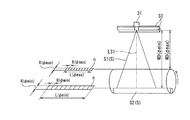
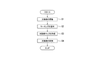
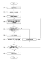
- FIG. 1 is a schematic configuration diagram of a defect grinding system to which a round steel material defect grinding method according to an embodiment of the present invention is applied. It is the figure which looked at the schematic structure of the marking detection apparatus in the defect grinding system shown in FIG. 1 from the front side. It is the figure which saw the schematic structure of the marking detection apparatus in the defect grinding system shown in FIG. 1 from the right side surface side. It is a figure for demonstrating the specification of the line sensor camera which comprises the imaging device in a marking detection apparatus. It is a flowchart which shows the procedure of the defect grinding method of the round steel material using the defect grinding system shown in FIG. It is a figure for explaining an example of a defective part map.
- step S4 defective part grinding process
- step S46 marking detection step
- step S463 marking extraction process
- FIG. 1 shows a schematic configuration of a defect grinding system to which a round steel material defect grinding method according to an embodiment of the present invention is applied.
- the defect grinding system 1 is manufactured by slab rolling or the like. It is provided in the middle of a transfer line that transfers the round steel material S to the downstream process.
- the defect grinding system 1 includes a leakage magnetic flux flaw detector (MLFT) 11A that detects surface defects as defective portions of the round steel material S, and an ultrasonic flaw detector (AUT) that detects surface layer defects as defective portions of the round steel material S. 11B and.
- MLFT leakage magnetic flux flaw detector
- AUT ultrasonic flaw detector
- the magnetic flux leakage flaw detection device 11A is installed at a place off the transport line and detects surface defects existing on the surface of the round steel material S that rotates in the circumferential direction on the turning roller 13A.
- the flaw detection of the surface defect of the round steel material S by the leakage magnetic flux flaw detector 11A is performed for one round in the circumferential direction over the entire length of the round steel material S in the longitudinal direction.
- the ultrasonic flaw detector 11B is installed on the downstream side with respect to the leakage magnetic flux flaw detector 11A, and is transferred by a transfer (not shown) from the turning roller 13A to the turning roller 13B.
- the surface layer defect of the round steel material S rotating in the circumferential direction is detected.
- the flaw detection of the surface layer defect of the round steel material S by the ultrasonic flaw detection device 11B is performed for one round in the circumferential direction over the entire length of the round steel material S in the longitudinal direction.
- the defect grinding system 1 also includes a first marking device 12A attached to the leakage magnetic flux flaw detector 11A and a second marking device 12B attached to the ultrasonic flaw detector 11B.
- the first marking device 12A applies the marking to the position of the surface defect having a predetermined depth or more (0.3 mm or more in the present embodiment) among the surface defects detected by the leakage magnetic flux flaw detector 11A.
- the leakage magnetic flux flaw detector 11A sends the depth information of the flaw detected surface defect to the first marking device 12A.
- the second marking device 12B applies the marking to the position of the surface defect having a predetermined depth or more (0.3 mm or more in the present embodiment) among the surface defects detected by the ultrasonic flaw detector 11B.
- the ultrasonic flaw detector 11B sends depth information of the detected surface layer defect to the second marking device 12B.
- the defect grinding system 1 determines the depths of the surface defects and the surface layer defects on the surface of the round steel S and the circumferences of the surface defects and the surface layer defects from the flaw detection results of the leakage magnetic flux flaw detector 11A and the ultrasonic flaw detector 11B.
- the defective portion map creation device 15 is provided that creates a defective portion map 50 (see FIG. 6) that specifies the directional position y and the longitudinal position x.
- the defect part map creation device 15 has a plurality of regions (in the present embodiment, along the longitudinal direction of the round steel product S on the surface of the round steel product S as shown in FIG. 6). Creates a defect portion map divided into 6 areas A to F.
- the depth of each surface defect and surface layer defect is shown as a number that is an integral multiple of 0.1 mm as 1.
- the leakage magnetic flux flaw detector 11A provides the defect portion map creation device 15 with the depth information of the flaw detected surface defect and the information of the longitudinal position x from the longitudinal end face of the round steel S of the surface defect (the end face is 0). Send out. Further, the turning roller 13A is provided with a pulse generator 14A as a rotation angle detector. The pulse generator 14A detects the rotation speed r of the turning roller 13A from the start of flaw detection by the leakage magnetic flux flaw detector 11A to the detection of surface defects.
- the defect portion map creation device 15 calculates the rotation angle from the flaw detection start point of the round steel material S to the flaw detection point of the surface defect from the above-described rotation speed r received from the pulse generator 14A, and this rotation angle and the round steel material S
- the circumferential length from the flaw detection start point in the circumferential direction of the round steel material S to the flaw detection point of the surface defect is calculated from the diameter and the circumferential position y of the surface defect is specified.
- the ultrasonic flaw detector 11B uses the depth information of the detected surface layer defect and the information of the longitudinal position x from the longitudinal end face of the round steel S of the surface defect (the end face is 0) to the defect portion map creation device. Send to 15. Further, the turning roller 13B is also provided with a pulse generator 14B as a rotation detector, and the pulse generator 14B rotates the rotating speed of the turning roller 13B from when the ultrasonic flaw detector 11B starts flaw detection until flaw detection of a surface defect. Detect r.
- the defect portion map creating device 15 calculates the rotation angle from the flaw detection start point of the round steel material S to the flaw detection point of the surface layer defect from the rotation speed r received from the pulse generator 14B, and this rotation angle and the round steel material S
- the circumferential length from the flaw detection start point in the circumferential direction of the round steel S to the flaw detection point of the surface layer defect is calculated from the diameter and the circumferential position y of the surface layer defect is specified.
- the defect grinding system 1 includes a defect part grinding device 20 that grinds surface defects and surface layer defects of the round steel material S.
- the defective portion grinding device 20 detects the marking M of each region corresponding to each region A to F on the defective portion map 50 on the surface of the round steel material S. Grind the place.
- the defective portion grinding device 20 is installed on the downstream side of the ultrasonic flaw detection device 11B, and moves on the turning roller 25 transferred from the turning roller 13B to the turning roller 25 by a transfer (not shown).
- the marking portion of each region of the round steel material S rotating in the direction or the entire surface of each region is ground (also referred to as surface grinding in the following description).
- the turning roller 25 is rotatably installed on a carriage 27 which is movable by a carriage drive device 28 between a defect grinding device 20 and a marking detection device 30 described later. Further, the turning roller 25 is provided with a pulse generator 26 as a rotation angle detector.
- the defective portion grinding device 20 includes a grinder 21 that grinds a marking portion of each region of the round steel material S or the entire surface of each region, a grinding control device 22 that controls the grinder 21 and the carriage driving device 28, and a turning roller 25.
- An end face detection sensor 24 that detects the end face of the upper round steel S in the longitudinal direction is provided.
- the grinding control device 22 is connected to the defect map creation device 15, the grinder 21, the host computer 23, the end face detection sensor 24, the pulse generator 26, the carriage drive device 28, the camera control device 32, which will be described later, and the development drawing creation device 38. There is. The function of the grinding control device 22 will be described in detail later.
- the grinding control device 22 is a computer system having an arithmetic processing function for realizing each function described later by executing a program on computer software.
- the computer system is configured to include a ROM, a RAM, a CPU, and the like, and each function is realized by software by executing various dedicated programs stored in the ROM or the like in advance.
- the defect grinding system 1 detects the marking M (see FIG. 12) applied to the position of the surface defect and the surface layer defect of the round steel material S according to the determination result (step S45) described later by the grinding control device 22.
- a detection device 30 is provided.
- the size of the round steel material S marked by the first marking device 12A and the second marking device 12B is any size between the minimum diameter ⁇ 80 mm and the maximum diameter ⁇ 450 mm.
- the maximum diameter round steel material is indicated by S1
- the minimum diameter round steel material is indicated by S2.
- the color of the marking applied to the position of the surface defect and the surface defect of the round steel material S by the first marking device 12A and the second marking device 12B is the same as the color of the illumination by the illumination device 5 (a color close to white). Different colors are preferred. As a result, the marking color and the illumination color are not confused with each other, and the marking can be easily detected.
- the marking detection device 30 takes a plurality of images of the surface of the round steel material S that rotates in the circumferential direction on the turning roller 25 on the carriage 27 that has been moved from the defect grinding device 20.
- the imaging device 31, the computer system 35, and the development drawing creation device 38 are provided.
- the turning roller 25 rotates the round steel material S in a circumferential direction (direction shown by an arrow in FIGS. 2 and 4) at a predetermined rotation speed (in the present embodiment, for example, about 1500 mm/s).
- a plurality of first support members 41 are attached to a plurality of support legs 40 erected on the pedestal 39 so as to be orthogonal to the support legs 40.
- the second support member 42 is attached to the first support member 41 so as to be orthogonal to the first support member 41.
- a plurality of third support members 43 are attached so as to be orthogonal to the support legs 40 at positions above the portions of the plurality of support legs 40 to which the first support members 41 are attached.
- a fourth support member 44 is attached to the third support member 43 so as to be orthogonal to the third support member 43.
- Each imaging device 31 is attached to the tip of the fourth support member 44.
- Each image pickup device 31 is composed of a line sensor camera, and as shown in FIG. 3, the direction in which the image pickup line of the line sensor camera extends and the axial direction of the round steel S coincide with each other, and as shown in FIG.
- the line sensor camera optical axis L31 and the tangent line TL in contact with the uppermost position P of the round steel material S are installed so that an angle ⁇ is 90 degrees.
- the angle ⁇ formed by the optical axis L31 and the tangent line TL is not limited to 90 degrees, and it is preferable that the acute side has a range of 30 degrees or more.
- the installation height of the line sensor camera which constitutes each image pickup device 31 is such that the distance WD between the lens of the line sensor camera and the round steel material S is a predetermined distance (of the round steel material S1 having the maximum diameter).
- the distance WD( ⁇ max) 900 mm
- the distance WD( ⁇ min) 1270 mm.
- a camera having a lens in focus is selected.
- the depth of field is set to 771 mm, and a lens that is in focus is selected regardless of whether the diameter of the round steel material S1 having the maximum diameter is ⁇ 450 mm and the diameter of the round steel material S2 having the minimum diameter is ⁇ 80 mm.
- each imaging device 31 has a marking M (FIG. 12) which is a measurement target at the uppermost position (specific position) P in the circumferential direction of the surface of the round steel material S which rotates on the turning roller 25 in the circumferential direction.
- An image of one round of the round steel material S is picked up at a predetermined cycle with a resolution smaller than the dimension of (see).
- P1 is the uppermost position of the surface of the round steel S1 having the largest diameter
- P2 is the uppermost position of the surface of the round steel S2 having the smallest diameter).
- the size of the marking M is a circle having a diameter of about 4 mm
- the resolution of the line sensor camera that is, the width R in the circumferential direction of each pixel n (see FIG. 4) of one line is a circle with the maximum diameter.
- the width R ( ⁇ max) in the circumferential direction of each pixel n when imaging the steel material S1 is 630 ⁇ m/pix
- the width R ( ⁇ min) in the circumferential direction of each pixel n when imaging the round steel material S2 having the minimum diameter is 889 ⁇ m/ It is pix.
- the cycle of imaging with the line sensor camera is 1/2381 s so that the rotation speed of the round steel material S is 1500 mm/s and the circumferential surface of the round steel material S can be imaged without gaps. Is becoming
- the circumferential imaging start point of the round steel material S by each imaging device 31 is the circumferential flaw detection starting point of the round steel material S by the leakage magnetic flux flaw detector 11A and the circumferential flaw detection of the round steel material S by the ultrasonic flaw detector 11B. Same as the starting point. Further, the number of pixels n of one line of the line sensor camera constituting each imaging device 31 is 2048 pix, and the axial width R ( ⁇ max) of each pixel n when imaging the round steel S1 having the maximum diameter is 630 ⁇ m/ Pix, the width R ( ⁇ min) in the axial direction of each pixel n when imaging the round steel material S2 having the smallest diameter is 889 ⁇ m/pix.
- the visual field width L ( ⁇ max) when capturing the maximum diameter round steel material S1 is 1290 mm
- the visual field width L ( ⁇ min) when capturing the minimum diameter round steel material S2 is 1821 mm.
- a plurality of imaging devices 31 are installed along the axial direction of the round steel material S so that the entire length of the round steel material S1 having the maximum diameter and the total length of the round steel material S2 having the minimum diameter can be imaged. Specifically, two imaging devices 31 are installed in each area corresponding to the areas A to F of the defect map of the round steel material S shown in FIG.
- the reason why the image pickup device 31 is a line sensor camera whose image pickup line extends in the axial direction of the round steel material S is as follows. That is, when the round steel material S is viewed from the axial direction, the surface of the round steel material S is circular. Therefore, when the imaging device 3 is an area sensor camera, the distance from the area sensor camera to the surface of the round steel material S is large. Are different along the circumferential direction, and the angle between the position on the surface of the round steel S when viewed from the axial direction of the round steel S and the straight line connecting the camera with the surface of the round steel S at this position is the circumferential direction. Different along.
- the imaging device 31 is an area sensor camera
- the appearance of the shape of the marking applied to the surface of the round steel S in the captured image changes along the circumferential direction of the round steel S.
- the straight line connecting the position on the surface of the round steel material S and the camera makes an acute angle with the surface of the round steel material S at this position, the area of the marking in the captured image becomes small and the marking and the noise can be discriminated. It gets harder.
- the image pickup device 31 is composed of a line sensor camera, and the image pickup device 3 is arranged so that the image pickup line extends in the axial direction of the round steel product S, and the position of the uppermost position P on the surface of the round steel product S rotating in the circumferential direction is set. Images are taken along the axial direction.
- the image at the uppermost position (specific position) P captured by the line sensor camera is taken as an image obtained by joining the images in the circumferential direction, and the marking is extracted from this image.
- the distance from the line sensor camera to the position of the uppermost position P on the surface of the round steel material S does not change, and the line connecting the camera and the uppermost position P does not change. Since the angle formed with the surface of the round steel material S at the uppermost position P is constant, such inconvenience is eliminated. Therefore, by using the image sensor 31 as a line sensor camera, it is possible to appropriately detect the shape of the marking applied to the surface of the round steel material S to be imaged.
- Each image pickup device 31 is connected to a power supply and a camera control device 32 that controls an image pickup cycle and the like, which are not shown. Further, the camera control device 32 is connected to the grinding control device 22 and receives the result of the determination (step S45) by the grinding control device 22.
- the camera control device 32 corresponds to the areas A to F when the determination result is YES (when the area ratio of the defective portions (surface defects and surface layer defects) in the areas A to F is less than a predetermined threshold value).
- a signal for starting imaging by the imaging device 31 is sent to the imaging device 31.
- the marking detection device 30 includes a plurality of illumination devices 33, as shown in FIGS. 2 to 4.
- Each lighting device 33 is rotatably attached to the tip of the second support member 42 described above.
- Each of the lighting devices 33 is composed of two rows of bar lights that continuously light up the surface of the round steel material S, particularly near the uppermost position P to be imaged. The color of the illumination is close to white.
- the angle ⁇ between the optical axis L33 of the lighting device 33 and the vertical line VL is from the vicinity of the uppermost position P2 of the round steel material S2 having the smallest diameter to the uppermost position P1 of the round steel material S1 having the largest diameter. It is adjustable so that it can be illuminated in all cases up to the vicinity.
- a plurality of lighting devices 33 are installed along the axial direction of the round steel material S so that the entire length of the round steel material S1 having the maximum diameter and the total length of the round steel material S2 having the minimum diameter can be illuminated.
- Each lighting device 33 is connected to a lighting power supply (not shown) and a lighting control device 34 that controls the brightness of the lighting and the like.
- the computer system 35 processes an image obtained by joining the images at the above-mentioned uppermost position (specific position) P captured by each image capturing device 31 in the circumferential direction, and an image processing unit 36.
- the marking extraction unit 37 that extracts the marking M (see FIG. 12) from the image subjected to the image processing in FIG.
- Each image pickup device 31 and the pulse generator 26 are connected to a computer system 35.
- the computer system 35 is a computer system having an arithmetic processing function for realizing each function of the image processing unit 36 and the marking extraction unit 37 by executing a program on computer software.
- the computer system is configured to include a ROM, a RAM, a CPU, and the like, and executes the various dedicated programs stored in the ROM or the like in advance to realize the above-described functions on software.
- the development drawing creation device 38 is based on the marking M extracted by the marking extraction unit 37, the circumferential position y of the marking M from the imaging start point, and the longitudinal position x of the marking M from the longitudinal end face.
- the development view 60 shown in FIG. 13 corresponds to the defect map 50 shown in FIG. 6, and a plurality of regions (6 in the present embodiment are provided on the surface of the round steel S in the longitudinal direction of the round steel S). Area) A to F, and a portion having a marking M is indicated by numeral 1. Then, the information of the development drawing creation device 38 is sent to the grinding control device 22.
- the functions of the image processing unit 36, the marking extraction unit 37, and the development drawing creation device 38 will be described in detail later.
- step S1 the leakage magnetic flux flaw detector 11A detects surface defects existing on the surface of the round steel material S rotating in the circumferential direction on the turning roller 13A, and the ultrasonic flaw detector 11B moves around the turning roller 13B.
- the surface layer defect of the round steel material S rotating in the direction is inspected (flaw detection step).
- the flaw detection of the surface defect of the round steel material S by the leakage magnetic flux flaw detector 11A is performed for one round in the circumferential direction over the entire length in the longitudinal direction of the round steel material S, and the flaw detection of the surface layer defect of the round steel material S by the ultrasonic flaw detection device 11B. Is performed for one round in the circumferential direction over the entire length of the round steel S in the longitudinal direction. Then, the leakage magnetic flux flaw detector 11A sends the depth information of the detected surface defect to the first marking device 12A, and the ultrasonic flaw detector 11B sends the depth information of the detected surface defect to the second marking device 12B. To do.
- the first marking device 12A marks the position of a surface defect having a predetermined depth or more (0.3 mm or more in the present embodiment) among the surface defects detected by the leakage magnetic flux flaw detector 11A.
- M (see FIG. 12) is applied, and the second marking device 12B has a surface layer defect of a predetermined depth or more (0.3 mm or more in the present embodiment) among the surface layer defects detected by the ultrasonic flaw detection device 11B.
- the marking M is applied to the position (marking step).
- the color of the marking applied to the position of the surface defect and the surface layer defect of the round steel material S by the first marking device 12A and the second marking device 12B is different from the color of the illumination by the illumination device 5 (a color approximate to white). It is preferably colored.
- the defect map creating device 15 determines the depths and surface defects of the surface defect and the surface layer defect on the surface of the round steel S from the flaw detection results of the leakage magnetic flux flaw detector 11A and the ultrasonic flaw detector 11B.
- a defect part map 50 (see FIG. 6) specifying the circumferential position y and the longitudinal position x of each surface defect is created (defect part map creating step).
- the defect part map creating device 15 creates a plurality of regions (in the present embodiment) along the longitudinal direction of the round steel product S on the surface of the round steel product S, as shown in FIG. In this case, the defect portion map 50 divided into 6 areas A to F is created.
- the depth of each surface defect and surface layer defect is shown as a number that is an integral multiple of 0.1 mm as 1.
- the leakage magnetic flux flaw detector 11A provides the defect portion map creation device 15 with the depth information of the flaw detected surface defect and the information of the longitudinal position x from the longitudinal end face of the round steel S of the surface defect (the end face is 0). Then, the defective portion map creating device 15 receives the information. Further, the defect portion map creating device 15 receives from the pulse generator 14A the rotation speed r of the turning roller 13A from the start of the flaw detection by the leakage magnetic flux flaw detector 11A to the flaw detection of the surface defect, and the rotation speed r and the turning speed r. From the diameter of the roller 13A, the circumferential length from the flaw detection start point of the round steel S to the flaw detection point of the surface defect is calculated, and the circumferential position y of the surface defect is specified.
- the ultrasonic flaw detector 11B uses the depth information of the detected surface layer defect and the information of the longitudinal position x from the longitudinal end face of the round steel S of the surface defect (the end face is 0) to the defect portion map creation device. Then, the defect portion map creating apparatus 15 receives the information. Further, the defect portion map creating device 15 receives the rotation speed r of the turning roller 13B from the pulse generator 14A until the ultrasonic flaw detection device 11B starts flaw detection to the flaw detection of the surface layer defect, and the rotation speed r and the turning speed r.
- the length in the circumferential direction from the flaw detection start point in the circumferential direction of the round steel material S to the flaw detection point of the surface layer defect is calculated from the diameter of the roller 13B, and the circumferential position y of the surface layer defect is specified.
- the defect part map creation device 15 sends the information of the defect part map 50 to the grinding control device 22.
- step S4 the defective portion grinding device 20 grinds surface defects and surface layer defects of the round steel material S (defective portion grinding step).
- step S41 the defective portion grinding device 20 receives the round steel material S.
- the acceptance of the round steel material S is achieved by transferring the round steel material S on the turning roller 13B onto the turning roller 25 on the carriage 27 by a transfer (not shown).
- step S42 the grinding control device 22 determines the grinding amount per pass.
- the grinding control device 22 acquires the product information of the round steel material S from the host computer 23 and determines the grinding amount per pass based on the product information of the round steel material S.
- step S43 the end face detection sensor 24 detects the end face of the round steel material S on the turning roller 25 in the longitudinal direction, and sends the information to the grinding control device 22.
- the grinding control device 22 controls the carriage drive device 28 to move the carriage 27 so that the longitudinal end surface of the round steel material S on the turning roller 25 is directly below the end surface detection sensor 24.
- step S44 the grinding control device 22 refers to the defect portion map 50, and circles corresponding to the regions A to F having defect portions (surface defects and surface layer defects) closest to the end face in the longitudinal direction of the round steel material S.
- the carriage drive device 28 is controlled so that the imaging device 31 is located in the region of the steel material S, and the carriage 27 is moved.
- step S45 the grinding control device 22 refers to the defect map 50 and has a depth equal to or greater than a predetermined depth in the area of the surface of the round steel material S corresponding to the corresponding areas A to F of the moving destination (in the present embodiment, in the present embodiment). It is determined whether the ratio of the area of the defective portion of 0.3 mm or more) is less than a predetermined threshold value (determination step).
- the predetermined threshold is The value is represented by a2/a1.
- step S461 the camera control device 32 receives the determination result from the grinding control device 22, and the area of the surface of the round steel material S corresponding to the corresponding areas A to F is detected.
- An image pickup start signal is sent to the image pickup device 31 that picks up the image.
- the line sensor camera configuring the image pickup device 31 causes the circumferential uppermost position of the area of the surface of the round steel S corresponding to the corresponding areas A to F of the round steel S rotating in the circumferential direction on the turning roller 25 (specific The position P is imaged for one round of the round steel material S with a resolution smaller than the dimension of the marking M to be measured at a predetermined cycle (imaging step).
- the size of the marking M is a circle having a diameter of about 4 mm
- the resolution of the line sensor camera that is, the circumferential width R of each pixel n (see FIG. 4) of one line is a circle with the maximum diameter.
- the width R ( ⁇ max) in the circumferential direction of each pixel n when imaging the steel material S1 is 630 ⁇ m/pix
- the width R ( ⁇ min) in the circumferential direction of each pixel n when imaging the round steel material S2 having the minimum diameter is 889 ⁇ m/ It is pix.
- the cycle of imaging with the line sensor camera is 1/2381 s so that the rotation speed of the round steel material S is 1500 mm/s, and the circumferential front surface of the round steel material S can be imaged without gaps.
- the circumferential imaging start point of the round steel material S by the imaging device 31 is the circumferential flaw detection starting point of the round steel material S by the leakage magnetic flux flaw detector 11A and the circumferential flaw detection start of the round steel material S by the ultrasonic flaw detection device 11B. Same as point.
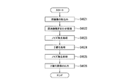
- step S462 the image processing unit 36 of the computer system 35 processes the image obtained by joining the images at the uppermost position (specific position) P captured by the line sensor camera constituting the imaging device 31 in the circumferential direction. Yes (image processing step).
- the image processing unit 36 firstly, the original image from the line sensor camera constituting the imaging device 31 (images at the plurality of uppermost positions P). Take in.
- step S4622 the image processing unit 36 joins the captured original images (images of the plurality of uppermost positions P) in the circumferential direction of the round steel material S.
- An example of an image after connecting the original images in the circumferential direction of the round steel materials S is shown in the upper part of FIG. 11. Since it is difficult to detect the marking M in an image obtained by joining the original images in the circumferential direction of the round steel materials S, the binarization processing is performed later.
- step S4623 the image processing unit 36 performs noise removal processing other than marking on the joined original images.
- step S4624 the image processing unit 36 performs binarization processing on the stitched original image from which noise has been removed.
- step S4625 the image processing unit 36 performs noise removal processing other than marking on the image after binarization processing.
- An example of the image after noise removal is shown in the middle part of FIG.
- step S4626 the binarized image from which noise has been removed is output to the marking extraction unit 37. This completes the image processing step.
- the marking extraction unit 37 of the computer system 35 extracts the marking M from the image subjected to the image processing in the image processing step (marking extraction step).
- marking extraction step will be described in detail.
- the marking extraction unit 37 takes in a binarized image from the image processing unit 36 in step S4631.
- step S4632 the marking extraction unit 37 determines that a region a (see FIG. 12) of a set of pixels n1 (see FIG. 12) having a pixel value 0 (white) having a predetermined area or more is included in the captured binarized image. Determine if there is. In FIG. 12, a pixel having a pixel value of 1 (black) is indicated by n2. Then, if the result of step S4632 is YES, the process proceeds to step S4633, and if the result is No, the process proceeds to step S4634.
- step S4633 the marking extraction unit 37 determines that the area a is the marking M, and in step S4635, the marking extraction unit 37 determines the circumferential position y and the longitudinal position x of the marking M (see the lower row in FIG. 11). Identify.
- the circumferential position y of the marking M means the circumferential length of the round steel material S from the imaging start point to the marking M in the circumferential direction.
- the number of rotations of the turning roller 25 is input from the pulse generator 26 to the marking extraction unit 37, and the marking extraction unit 37 determines the circumferential direction of the round steel material S from the input number of rotations of the turning roller 25 and the diameter of the turning roller 25.
- the length in the circumferential direction from the image pickup start point to the marking M is calculated, and the circumferential position y of the marking M is specified.
- the longitudinal position x of the marking M means the axial length from the end face of the round steel material S in the axial direction to the marking M.
- the marking extraction unit 9 determines the number of pixels n from the end surface in the axial direction of the round steel material S to the marking M and the axial width R of each pixel n from the end surface in the axial direction of the round steel material S to the marking M.
- the length in the axial direction is calculated and the longitudinal position x of the marking M is specified.
- the marking extraction unit 37 outputs the marking extraction result to the development drawing creation device 38 in step S4636.
- An example of the marking extraction result is shown in the lower part of FIG. 11, and the marking M and the circumferential position y and the longitudinal position x of the marking M are extracted. In the lower part of FIG. 11, the circumferential position of the specific marking M is indicated by y1 and the longitudinal position thereof is indicated by x1.
- the marking extraction unit 37 determines that there is no marking M, and outputs the result to the development drawing creation device 38 in step S4636.
- step S464 the development view creation device 38 creates the development view 60.
- FIG. 13 shows an example in which a developed view 60 is created for each area corresponding to all areas A to F, and the place where the marking M is present is indicated by numeral 1.
- the development drawing creation device 38 is shown in FIG. 13 based on the marking M extracted by the marking extraction unit 37, the circumferential position y of the marking M from the imaging start point, and the longitudinal position x of the marking M from the end face in the longitudinal direction.
- a development drawing 60 is created.
- the information from the development drawing creation device 38 is sent to the grinding control device 22. As a result, the marking extraction step ends, and the marking detection step ends.
- step S47 the grinding control device 22 controls the grinder 21, the carriage driving device 28, and the turning roller 25 to make the circles corresponding to the corresponding areas A to F.
- a portion of the marking M extracted in the marking detection step in the surface area of the steel material S is ground (marking portion grinding step).
- This marking point grinding step will be described in detail, as shown in FIG. 14, first, the grinding control device 22 acquires the extraction result of the marking M in step S471. Specifically, the grinding control device 22 acquires information from the development drawing creation device 38.
- step S472 the grinding control device 22 determines whether or not the marking M on the development view 60 continuously extends over a plurality of regions on the defect map 50. Then, if the determination result is No, that is, if the marking M on the developed view 60 does not continuously extend over a plurality of regions on the defect map 50, in step S473, the round steel materials S corresponding to the corresponding regions A to F are obtained. The area of the marking M on the surface of the area is grinded individually.
- the grinding control device 22 determines the grinding position alignment of the round steel material S in the longitudinal direction with reference to the defect map 50 shown in FIG. That is, the longitudinal position x of the defective portion on the defective portion map 50 is set as the longitudinal grinding position for grinding.
- the grinding control device 22 determines the grinding position alignment of the round steel material S in the circumferential direction with reference to the extraction result of the marking M. Assuming that the circumferential position y of the defective portion on the defective portion map 50 is the grinding position in the circumferential direction, when the roundness of the round steel material S is low, a deviation occurs between the position of the defective portion and the grinding position. This is because grinding may be performed, and re-inspection or re-grinding may be required, which may hinder production efficiency.
- the grinding control device 22 rotates the round steel material S in the circumferential direction with the turning roller 25 while referring to the development view 60 which is the extraction result of the marking M, and when the imaging device 31 projects the marking M, the rotation is performed.
- the rotation of the round steel material S is stopped at the position, and the grinding position is set in the circumferential direction.
- the grinding control device 22 controls the movement of the carriage 27 in the longitudinal direction so that the marking M is directly below the grinder 21 while the rotation of the round steel material S is stopped, and in that state, the grinding of the marking M by the grinder 21 is performed.
- the grinding position in the longitudinal direction at this time is the longitudinal position x of the defective portion on the above-described defective portion map 50.
- the grinding control device 22 determines the grinding depth by collating the defect map 50 and the extraction results of the markings M. Specifically, the longitudinal position x and the circumferential position y of a plurality of defective portions in the corresponding areas A to F on the defective portion map 50, the depth of each defective portion, and the plurality of markings M on the developed view 60. The longitudinal position x and the circumferential position y are collated to detect the depth of the defective portion corresponding to each marking M. Then, the grinding control device 22 determines the maximum depth among the depths of the plurality of defective portions corresponding to the plurality of markings M in the detected corresponding areas A to F. Then, the maximum depth of this defective portion is set as the grinding depth of the plurality of markings M in the corresponding areas A to F.
- the grinding depth of the marking M is divided by the grinding amount per pass determined in step S42 to determine the number of times of grinding.
- the maximum depth among the depths of the plurality of defective portions corresponding to the plurality of markings M in the corresponding areas A to F is set to d max, and the grinding per pass determined in step S42.
- the amount is defined as g, and d max /g is calculated.
- the obtained d max / g is the greater than the permissible limit number N max is the allowable limit number N max grinding times.
- the grinding control device 22 grinders 21 and the truck drive device 28 so as to individually grind the portions of the marking M on the surface of the round steel material S in the areas of the round steel material S corresponding to the corresponding areas A to F with this number of grindings. And controlling the turning roller 25. As a result, all the portions of the marking M on the surface of the region of the round steel material S corresponding to the corresponding regions A to F are ground.
- the determination result in step S472 is No, that is, if the marking M on the developed view 60 continuously extends over a plurality of regions on the defect map 50, at step S474, the area of the round steel material S that extends over the plurality of regions is determined. The portion of the marking M on the surface is continuously ground.
- the grinding control device 22 determines the grinding position alignment of the round steel S in the longitudinal direction with reference to the defect map 50 shown in FIG. 6, as in the individual grinding of the marking M in step S474. Further, the grinding control device 22 determines the grinding position alignment of the round steel material S in the circumferential direction with reference to the extraction result of the marking M. Further, the grinding control device 22 determines the grinding depth by collating the extraction result of the defect map 50 and the marking M.
- the longitudinal position x and the circumferential position y of the defective portion and the depth of each defective portion in the plurality of regions on the defective portion map 50, the longitudinal position x of the plurality of markings M on the developed view 60, and The depth y of the defective portion corresponding to each marking M is detected by collating with the circumferential position y.
- the grinding control device 22 obtains the maximum depth of the plurality of defective portions corresponding to the marking M in the detected plurality of regions. Then, the maximum depth of the defective portion is set as the grinding depth of the plurality of markings M in the continuous grinding. Then, the grinding depth of the marking M is divided by the grinding amount per pass determined in step S42 to determine the number of times of grinding.
- the maximum depth among the depths of the defective portions corresponding to the markings M in a plurality of continuously extending regions is set as d max, and the grinding amount per pass determined in step S42 is g.
- d max /g is calculated. Then, the obtained d max / g is the greater than the permissible limit number N max is the allowable limit number N max grinding times. As a result, the marking point grinding process in step 47 is completed.
- step S45 when the determination result in step S45 is No and the process shifts to step S49, that is, the grinding control device 22 refers to the defect map and the surface of the round steel material S corresponding to the corresponding areas A to F of the movement destination.
- the grinding control device 22 causes the grinder 21 and the carriage to move.
- the drive device 28 and the turning roller 25 are controlled to grind the entire surface area of the surface of the round steel material S corresponding to the corresponding areas A to F (entire surface grinding step).
- the marking M is not detected, and the entire surface area of the surface of the round steel material S corresponding to the corresponding areas A to F is uniformly ground.
- the grinding control device 22 determines the grinding position alignment of the round steel material S in the longitudinal direction and the circumferential direction with reference to the defect portion map 50 shown in FIG.
- the grinding control device 22 refers to the defect map 50 to find the maximum depth of the plurality of defective parts in the corresponding regions A to F, and determines the maximum depth of the defective parts in the corresponding regions A to F.
- the grinding depth in step S42 is divided by the grinding amount per pass determined in step S42 to determine the number of times of grinding.
- the method of setting the allowable limit number of times N max to the maximum number of times of grinding is the same as the grinding of the marking portion in step S47. Then, after steps S47 and S49 are completed, in step S48, the grinding control device 22 determines whether or not any defective portion remains on the defective portion map shown in FIG.
- step S44, step S45, step S46, step S47, step S49, and step S48 are repeated. That is, when the grinding work is completed for the area A, step S44, step S45, step S46, step S47, step S49, and step S48 are repeated in the order of area B, area C, area D, area E, and area F. If the determination result is No, the process proceeds to step S50, and the defective portion grinding device 20 dispenses the round steel material S. This completes the defect grinding method for the round steel material S.
- the flaw detection step (step S1) for flaw detection of the round steel material S and the defect portion having a predetermined depth or more detected by the flaw detection step are performed.
- a defect portion map creating step (step S3) of creating 50 and a defect portion grinding step (step S4) of grinding a defective portion of the round steel material S are provided.
- the defective portion grinding step is a determination step (step S45) of referring to the defective portion map 50 and determining whether the ratio of the area a1 of the defective portion having a predetermined depth or more on the surface of the round steel material S is less than a predetermined threshold value.
- the ratio of the area a1 of the defect portion having a predetermined depth or more on the surface of the round steel material S determined in the determination step is less than a predetermined threshold value
- the circumferential image of the surface of the round steel material S is image-processed and marked.
- a marking detection step of extracting M (step S46), a marking portion grinding step of grinding the portion of the marking M extracted in the marking detection step (step S47), and a predetermined process on the surface of the round steel material S determined in the determination step.
- a full-surface grinding step (step S49) of performing full-surface grinding of the surface of the round steel material S when the ratio of the area of the defective portion having a depth or more to a predetermined threshold value or more is provided. Then, in the marking portion grinding step, the grinding position alignment in the longitudinal direction of the round steel material S is determined by referring to the defect map 50, and the grinding position alignment in the circumferential direction of the round steel material S is referred to by the extraction result of the marking M. The grinding depth is determined by collating the defect map 50 and the extraction result of the marking M.
- a round steel defect grinding method capable of automatically grinding a defective portion of a round steel material with inexpensive equipment without erroneous grinding that causes a deviation between the position of the defective portion and the grinding position. it can.
- an origin marking device for attaching an origin mark, which serves as a reference in the circumferential direction and the longitudinal direction of the round steel material S, to the round steel material S is unnecessary, and the cost for introducing and maintaining the same increases. There is no. Further, by performing image processing on the image of the surface of the round steel material S in the circumferential direction to extract the marking M, it is not necessary for the operator to visually find the marking M, and there is no risk of overlooking.
- the method for manufacturing a steel product according to the present invention is a method for feeding a round steel product having a defective portion surface-ground to the post-process by the defect grinding method for a round steel product according to the above-described embodiment of the present invention.
- the post-process refers to all the subsequent process steps for the round steel material whose surface is defectively ground. That is, when the round steel product is a bar steel product such as a round bar steel or a product steel pipe, it is a refining process, a shipping process or the like performed after defect grinding.
- the round steel material is a material for rolling, it includes a rolling process, a refining process performed thereafter, a shipping process, and the like.
- the defect grinding method for a round steel product according to the present invention by the defect grinding method for a round steel product according to the present invention, the round steel from which the defects have been removed without being erroneously ground is sent to the post-process, so that in the post-process, Disability can be suppressed. That is, when the post-process is a rolling process, it is possible to suppress defects such as a defect caused by a defective portion remaining due to erroneous grinding in the steel material after rolling, or a breakage caused by the defective portion during rolling. In addition, when the subsequent process is the refining process or the shipping process, it is possible to suppress the obstacle that the defective product flows out.
- the steel material at the stage of grinding defects is a round steel material, that is, if it is a steel material with a circular cross section
- the steel material after being treated in the post-process does not necessarily have to be a round steel material, and after being processed in the post-process.
- the steel material may be a steel material having a square cross section.
- the defect grinding method of the round bar steel according to the present invention includes defect grinding of a material, defect grinding of a bar product. Applicable to both. That is, in the method for manufacturing a steel material according to the present invention, when both the material and the product are round bar steel, the defect grinding of the present invention may be used only for the defect grinding of the material, or the defect of the product The defect grinding of the present invention may be used only for grinding, or the defect grinding of the present invention may be used for both material defect grinding and product defect grinding.
- a determination step of referring to the defective portion map 50 and determining whether the ratio of the area a1 of the defective portion having a predetermined depth or more on the surface of the round steel S is less than a predetermined threshold value is not always necessary.
- the marking detection step (step S45) is directly performed, and the entire surface grinding step (step S49) is not performed.
- the marking portion grinding step (step S47) of grinding the portion is always performed.
- the step (step S472) in which the grinding control device 22 determines whether the marking M on the developed view 60 continuously extends over a plurality of regions on the defect map 50 is determined. It is not absolutely necessary. In this case, after step S471, the step (step S473) of individually grinding the portions of the marking M on the surface of the round steel material S is directly performed, and the continuous grinding step (step S474) is not performed. Further, the defect part map 50 is divided into a plurality of areas A to F, but the number of divisions is not limited to this, and may be one area without being divided into a plurality of areas.
- the determination process refers to the defect map 50 to determine whether the ratio of the area of the defect having a predetermined depth or more to the entire surface of the round steel S is less than the predetermined threshold. To judge.
- the marking detection step in the case where the ratio of the area of the defective portion having a predetermined depth or more in the entire surface of the round steel material S determined in the determination step is less than a predetermined threshold value, the circumference of the entire surface of the round steel material S is determined.
- the marking M is extracted by image-processing the image in the direction. Further, in the marking portion grinding step, the portion of the marking M extracted in the marking detection step on the entire surface of the round steel material S is ground.
- a range in which an angle ⁇ (acute angle side) formed between the line connecting the imaging device 31 and the position P on the surface of the round steel S to be imaged and the surface of the round steel S at the position P on the surface is 30 degrees or more.
- ⁇ is 30 degrees or more, it becomes easier to distinguish the marking from the noise, and the marking detection accuracy is improved.
Landscapes
- Engineering & Computer Science (AREA)
- Mechanical Engineering (AREA)
- Physics & Mathematics (AREA)
- Optics & Photonics (AREA)
- General Physics & Mathematics (AREA)
- Investigating Materials By The Use Of Optical Means Adapted For Particular Applications (AREA)
- Constituent Portions Of Griding Lathes, Driving, Sensing And Control (AREA)
- Finish Polishing, Edge Sharpening, And Grinding By Specific Grinding Devices (AREA)
- Length Measuring Devices By Optical Means (AREA)
- Investigating Or Analyzing Materials By The Use Of Magnetic Means (AREA)
Abstract
欠陥部の位置と研削位置との間にずれが生じる誤研削が行われることなく丸鋼材の欠陥部を自動で研削することができる丸鋼材の欠陥研削方法および鋼材の製造方法を提供する。丸鋼材の欠陥研削方法は、探傷工程(ステップS1)で探傷した所定深さ以上の欠陥部にマーキングMを塗布するマーキング工程(ステップS2)と、探傷工程での探傷結果から欠陥部マップ(50)を作成する欠陥部マップ作成工程(ステップS3)と、欠陥部を研削する欠陥部研削工程(ステップS4)とを備える。欠陥部研削工程におけるマーキング箇所研削工程(ステップS47)では、丸鋼材Sの長手方向の研削位置合わせは欠陥部マップ(50)を参照して決定し、丸鋼材Sの周方向の研削位置合わせはマーキング検出工程(ステップS46)によるマーキング(M)の抽出結果を参照して決定し、研削深さは欠陥部マップ(50)及びマーキング(M)の抽出結果を照合して決定する。
Description
本発明は、丸鋼材の表面欠陥や表層欠陥などの欠陥部を自動研削する丸鋼材の欠陥研削方法および鋼材の製造方法に関する。
一般に、断面が円形の丸鋼片(例えば丸ビレット)は、鋳造で直接製造されたり、あるいは鋳造された鋼片を分塊圧延することによって製造される。そして、丸鋼片は、その製造工程で表面欠陥(開口欠陥)や表層欠陥(内部欠陥)が生じていることが多い。これらの欠陥部は、後工程で障害となる。すなわち、例えば、丸鋼片を熱間圧延する場合には、熱間圧延後の鋼材にこれらの欠陥部が起因となった疵が残ってしまったり、熱間圧延時に鋼材の破断が生じてしまったりする等の障害が発生する。したがって、後工程へ丸鋼片を送る前に、欠陥部を研削してなくす所謂「手入れ作業」が行われている。また、丸棒鋼のような条鋼製品や製品鋼管も製造工程で欠陥部を生じることがあるため、条鋼製品や製品鋼管等の丸棒鋼についても手入れ作業が行われている。
従来の丸棒材の表面欠陥及び表層欠陥を研削する丸棒材の欠陥自動研削方法として、例えば、特許文献1に示すものが知られている。
特許文献1に示す丸棒材の自動研削方法は、丸棒材と探傷ヘッドを相対的に回転させつつ進行させながら探傷し、探傷結果に応じて欠陥部分を研削するものである。そして、この自動研削方法は、疵マップ作成時に基準となる原点マークを材料に付し、原点マークを基準に、材料の表面欠陥を探傷し、原点マークを基準に、材料の表層欠陥の深さ位置を測定して探傷し、原点マークを基準に、表面欠陥の疵マップと表層欠陥の疵マップを合成して、同一箇所に存在する表面欠陥と表層欠陥の最大深さを求め、研削すべき欠陥の位置と深さを設定するようにしている。
この特許文献1に示す丸棒材の自動研削方法によれば、表面欠陥と表層欠陥を、過研削することなく、研削可能とすることができる。
特許文献1に示す丸棒材の自動研削方法は、丸棒材と探傷ヘッドを相対的に回転させつつ進行させながら探傷し、探傷結果に応じて欠陥部分を研削するものである。そして、この自動研削方法は、疵マップ作成時に基準となる原点マークを材料に付し、原点マークを基準に、材料の表面欠陥を探傷し、原点マークを基準に、材料の表層欠陥の深さ位置を測定して探傷し、原点マークを基準に、表面欠陥の疵マップと表層欠陥の疵マップを合成して、同一箇所に存在する表面欠陥と表層欠陥の最大深さを求め、研削すべき欠陥の位置と深さを設定するようにしている。
この特許文献1に示す丸棒材の自動研削方法によれば、表面欠陥と表層欠陥を、過研削することなく、研削可能とすることができる。
また、従来の丸鋼材の表面疵手入れ装置として、例えば、特許文献2に示すものが知られている。
特許文献2に示す丸鋼材の表面疵手入れ装置は、回転している丸鋼材の軸線方向に沿い往復移動自在で、丸鋼材と接触して表面疵を検出する表面疵検査装置と、検出された表面疵の位置にマーキング液を噴射して印を付けるマーキング装置と、マーキングされた表面疵を手入れする作業デッキとを備えている。
この特許文献2に示す丸鋼材の表面疵手入れ装置によれば、検出された表面疵の位置をマーキングするようにしたので、作業者の研削位置判断を正確にし、研削作業を迅速に行うことができる。
特許文献2に示す丸鋼材の表面疵手入れ装置は、回転している丸鋼材の軸線方向に沿い往復移動自在で、丸鋼材と接触して表面疵を検出する表面疵検査装置と、検出された表面疵の位置にマーキング液を噴射して印を付けるマーキング装置と、マーキングされた表面疵を手入れする作業デッキとを備えている。
この特許文献2に示す丸鋼材の表面疵手入れ装置によれば、検出された表面疵の位置をマーキングするようにしたので、作業者の研削位置判断を正確にし、研削作業を迅速に行うことができる。
しかしながら、この従来の特許文献1に示す丸棒材の自動研削方法及び特許文献2に示す丸鋼材の表面疵手入れ装置にあっては、以下の問題点があった。
即ち、特許文献1に示す丸棒材の自動研削方法の場合、疵マップ作成時に、丸棒材の周方向及び長手方向の基準となる原点マークを丸棒材に付ける原点マーキング装置が必要であり、その導入やメンテナンスに費用が嵩み、コストを安価にすることができなかった。また、丸棒材の真円度が低い場合には、欠陥部の位置と研削位置との間にずれが生じる誤研削が行われることがあり、再度の検査や再研削が必要になり、生産能率を阻害することがあった。
即ち、特許文献1に示す丸棒材の自動研削方法の場合、疵マップ作成時に、丸棒材の周方向及び長手方向の基準となる原点マークを丸棒材に付ける原点マーキング装置が必要であり、その導入やメンテナンスに費用が嵩み、コストを安価にすることができなかった。また、丸棒材の真円度が低い場合には、欠陥部の位置と研削位置との間にずれが生じる誤研削が行われることがあり、再度の検査や再研削が必要になり、生産能率を阻害することがあった。
また、特許文献2に示す丸鋼材の表面疵手入れ装置の場合、検出された表面疵の位置に塗布されたマーキングを作業者が目視により見つけ、その箇所を研削するようにしている。
ここで、丸鋼材の表面疵の位置に塗布されるマーキングは、マーキング液の吹付け具合によりその大きさや形が変わることがあり、作業者が目視で見つけにくい場合がある。従って、作業者の目視によってマーキングを見つける方法では、マーキングを見逃すリスクが大きく、この結果として、欠陥部の位置と研削位置との間にずれが生じる誤研削が行われることがあり、除去されるべき疵のすべてを除去しきれていない丸鋼材が後工程へ送られてしまうことがあった。
ここで、丸鋼材の表面疵の位置に塗布されるマーキングは、マーキング液の吹付け具合によりその大きさや形が変わることがあり、作業者が目視で見つけにくい場合がある。従って、作業者の目視によってマーキングを見つける方法では、マーキングを見逃すリスクが大きく、この結果として、欠陥部の位置と研削位置との間にずれが生じる誤研削が行われることがあり、除去されるべき疵のすべてを除去しきれていない丸鋼材が後工程へ送られてしまうことがあった。
従って、本発明は、これら従来の問題点を解決するためになされたものであり、その目的は、欠陥部の位置と研削位置との間にずれが生じる誤研削が行われることなく、安価な設備で丸鋼材の欠陥部を自動で研削することができる丸鋼材の欠陥研削方法、および、この欠陥研削方法を用いた鋼材の製造方法を提供することにある。
上記目的を達成するために、本発明の一態様に係る丸鋼材の欠陥研削方法は、丸鋼材の欠陥部を自動研削する丸鋼材の欠陥研削方法であって、前記丸鋼材の前記欠陥部を探傷する探傷工程と、該探傷工程で探傷した所定深さ以上の前記欠陥部にマーキングを塗布するマーキング工程と、前記探傷工程での探傷結果から前記丸鋼材の表面における前記欠陥部の深さと前記欠陥部の周方向位置及び長手方向位置とを特定した欠陥部マップを作成する欠陥部マップ作成工程と、前記丸鋼材の前記欠陥部を研削する欠陥部研削工程とを備え、該欠陥部研削工程は、前記丸鋼材の表面の周方向の画像を画像処理して前記マーキングを抽出するマーキング検出工程と、該マーキング検出工程で抽出された前記マーキングの箇所を研削するマーキング箇所研削工程とを備え、該マーキング箇所研削工程では、前記マーキングの箇所の前記丸鋼材における長手方向位置合わせは前記欠陥部マップを参照して決定し、前記マーキングの箇所の前記丸鋼材における周方向位置合わせは前記マーキングの抽出結果を参照して決定し、前記マーキングの箇所の研削深さは前記欠陥部マップ及び前記マーキングの抽出結果を参照して決定することを要旨とする。
また、本発明の別の態様に係る丸鋼材の欠陥研削方法は、丸鋼材の欠陥部を自動研削する丸鋼材の欠陥研削方法であって、前記丸鋼材の前記欠陥部を探傷する探傷工程と、該探傷工程で探傷した所定深さ以上の前記欠陥部にマーキングを塗布するマーキング工程と、前記探傷工程での探傷結果から前記丸鋼材の表面における前記欠陥部の深さと前記欠陥部の周方向位置及び長手方向位置とを特定した欠陥部マップを作成する欠陥部マップ作成工程と、前記丸鋼材の前記欠陥部を研削する欠陥部研削工程とを備え、該欠陥部研削工程は、前記欠陥部マップを参照して前記丸鋼材の表面における所定深さ以上の前記欠陥部の面積の割合が所定の閾値未満かを判定する判定工程と、該判定工程で判定された前記丸鋼材の表面における所定深さ以上の前記欠陥部の面積の割合が前記所定の閾値未満の場合に、前記丸鋼材の表面の周方向の画像を画像処理して前記マーキングを抽出するマーキング検出工程と、該マーキング検出工程で抽出された前記マーキングの箇所を研削するマーキング箇所研削工程と、前記判定工程で判定された前記丸鋼材の表面における所定深さ以上の前記欠陥部の面積の割合が所定の閾値以上の場合に、前記丸鋼材の表面の全面研削を行う全面研削工程とを備え、前記マーキング箇所研削工程では、前記マーキングの箇所の前記丸鋼材における長手方向位置合わせは前記欠陥部マップを参照して決定し、前記マーキングの箇所の前記丸鋼材における周方向位置合わせは前記マーキングの抽出結果を参照して決定し、前記マーキングの箇所の研削深さは前記欠陥部マップ及び前記マーキングの抽出結果を参照して決定することを要旨とする。
また、本発明の別の態様に係る鋼材の製造方法は、断面が円形の丸鋼材を、該丸鋼材の欠陥部を表面研削した後に、後工程で処理する鋼材の製造方法であって、前記表面研削は、前述した本発明の一態様あるいは別の態様に係る丸鋼材の欠陥研削方法を実施することを要旨とする。
本発明に係る丸鋼材の欠陥研削方法によれば、欠陥部の位置と研削位置との間にずれが生じる誤研削が行われることなく、安価な設備で丸鋼材の欠陥部を自動で研削することができる丸鋼材の欠陥研削方法を提供できる。また、本発明に係る鋼材の製造方法によれば、上記した誤研削を抑制できるので、後工程での障害、あるいは、欠陥のある製品の流出を抑制した、鋼材の製造方法を提供できる。
以下、本発明の実施の形態を図面を参照して説明する。以下に示す実施形態は、本発明の技術的思想を具体化するための装置や方法を例示するものであって、本発明の技術的思想は、構成部品の材質、形状、構造、配置等を下記の実施形態に特定するものではない。また、図面は模式的なものである。そのため、厚みと平面寸法との関係、比率等は現実のものとは異なることに留意すべきであり、図面相互間においても互いの寸法の関係や比率が異なる部分が含まれている。
図1には、本発明の一実施形態に係る丸鋼材の欠陥研削方法が適用される欠陥研削システムの概略構成が示されており、この欠陥研削システム1は、分塊圧延などによって製造された丸鋼材Sを下流工程へ搬送する搬送ラインの途中に設けられる。
この欠陥研削システム1は、丸鋼材Sの欠陥部としての表面欠陥を探傷する漏洩磁束探傷装置(MLFT)11Aと、丸鋼材Sの欠陥部としての表層欠陥を探傷する超音波探傷装置(AUT)11Bとを備えている。
この欠陥研削システム1は、丸鋼材Sの欠陥部としての表面欠陥を探傷する漏洩磁束探傷装置(MLFT)11Aと、丸鋼材Sの欠陥部としての表層欠陥を探傷する超音波探傷装置(AUT)11Bとを備えている。
漏洩磁束探傷装置11Aは、搬送ラインから外れた場所に設置され、ターニングローラ13A上を周方向に回転する丸鋼材Sの表面に存在する表面欠陥を探傷する。漏洩磁束探傷装置11Aによる丸鋼材Sの表面欠陥の探傷は、丸鋼材Sの長手方向の全長にわたって周方向の一周分につき行う。また、超音波探傷装置11Bは、漏洩磁束探傷装置11Aに対して下流側に設置されており、ターニングローラ13A上からターニングローラ13B上にトランスファー(図示せず)によって移送された、ターニングローラ13B上を周方向に回転する丸鋼材Sの表層欠陥を探傷する。超音波探傷装置11Bによる丸鋼材Sの表層欠陥の探傷は、丸鋼材Sの長手方向の全長にわたって周方向の一周分につき行う。
また、欠陥研削システム1は、漏洩磁束探傷装置11Aに付設された第1マーキング装置12Aと、超音波探傷装置11Bに付設された第2マーキング装置12Bとを備えている。第1マーキング装置12Aは、漏洩磁束探傷装置11Aによって探傷された表面欠陥のうち所定深さ以上(本実施形態にあっては0.3mm以上)の表面欠陥の位置にマーキングを塗布する。漏洩磁束探傷装置11Aは、探傷した表面欠陥の深さ情報を第1マーキング装置12Aに送出する。また、第2マーキング装置12Bは、超音波探傷装置11Bによって探傷された表層欠陥のうち所定深さ以上(本実施形態にあっては0.3mm以上)の表層欠陥の位置にマーキングを塗布する。超音波探傷装置11Bは、探傷した表層欠陥の深さ情報を第2マーキング装置12Bに送出する。
更に、欠陥研削システム1は、漏洩磁束探傷装置11A及び超音波探傷装置11Bのそれぞれの探傷結果から丸鋼材Sの表面における表面欠陥及び表層欠陥のそれぞれの深さと表面欠陥及び表層欠陥のそれぞれの周方向位置y及び長手方向位置xとを特定した欠陥部マップ50(図6参照)を作成する欠陥部マップ作成装置15を備えている。欠陥部マップ作成装置15は、欠陥部マップ50を作成する際に、図6に示すように、丸鋼材Sの表面における丸鋼材Sの長手方向に沿って複数の領域(本実施形態にあっては、6個の領域)A~Fに分割した欠陥部マップを作成する。図6に示す欠陥部マップ50において、各表面欠陥及び表層欠陥の深さは、0.1mmを1としてその整数倍の数字で示してある。
漏洩磁束探傷装置11Aは、探傷した表面欠陥の深さ情報及び表面欠陥の丸鋼材Sの長手方向端面(当該端面を0とする)からの長手方向位置xの情報を欠陥部マップ作成装置15に送出する。また、ターニングローラ13Aには、回転角度検出器としてのパルスジェネレータ14Aが設けられている。パルスジェネレータ14Aは、漏洩磁束探傷装置11Aが探傷を開始してから表面欠陥を探傷するまでのターニングローラ13Aの回転数rを検出する。欠陥部マップ作成装置15は、パルスジェネレータ14Aから受信した前述の回転数rから丸鋼材Sの探傷開始点から表面欠陥の探傷点までの回転角度を算出し、この回転角度と、丸鋼材Sの直径とから丸鋼材Sの周方向における探傷開始点から当該表面欠陥の探傷点までの周方向の長さを算出し、表面欠陥の周方向位置yを特定する。
また、超音波探傷装置11Bは、探傷した表層欠陥の深さ情報及び表層欠陥の丸鋼材Sの長手方向端面(当該端面を0とする)からの長手方向位置xの情報を欠陥部マップ作成装置15に送出する。また、ターニングローラ13Bにも、回転検出器としてのパルスジェネレータ14Bが設けられ、パルスジェネレータ14Bは、超音波探傷装置11Bが探傷を開始してから表面欠陥を探傷するまでのターニングローラ13Bの回転数rを検出する。欠陥部マップ作成装置15は、パルスジェネレータ14Bから受信した前述の回転数rから丸鋼材Sの探傷開始点から表層欠陥の探傷点までの回転角度を算出し、この回転角度と、丸鋼材Sの直径とから丸鋼材Sの周方向における探傷開始点から当該表層欠陥の探傷点までの周方向の長さを算出し、表層欠陥の周方向位置yを特定する。
また、欠陥研削システム1は、丸鋼材Sの表面欠陥及び表層欠陥を研削する欠陥部研削装置20を備えている。
この欠陥部研削装置20は、後述のマーキング検出装置30によってマーキングが抽出された場合には、丸鋼材Sの表面における欠陥部マップ50上の各領域A~Fに対応する各領域のマーキングMの箇所を研削する。
欠陥部研削装置20は、超音波探傷装置11Bに対して下流側に設置されており、ターニングローラ13B上からターニングローラ25上にトランスファー(図示せず)によって移送された、ターニングローラ25上を周方向に回転する丸鋼材Sの各領域のマーキングの箇所あるいは各領域の全面を研削(以下の説明では、表面研削とも云う)する。ターニングローラ25は、欠陥部研削装置20と後述のマーキング検出装置30との間を台車駆動装置28によって移動可能な台車27上に回転可能に設置されている。また、ターニングローラ25には、回転角度検出器としてのパルスジェネレータ26が設けられている。
この欠陥部研削装置20は、後述のマーキング検出装置30によってマーキングが抽出された場合には、丸鋼材Sの表面における欠陥部マップ50上の各領域A~Fに対応する各領域のマーキングMの箇所を研削する。
欠陥部研削装置20は、超音波探傷装置11Bに対して下流側に設置されており、ターニングローラ13B上からターニングローラ25上にトランスファー(図示せず)によって移送された、ターニングローラ25上を周方向に回転する丸鋼材Sの各領域のマーキングの箇所あるいは各領域の全面を研削(以下の説明では、表面研削とも云う)する。ターニングローラ25は、欠陥部研削装置20と後述のマーキング検出装置30との間を台車駆動装置28によって移動可能な台車27上に回転可能に設置されている。また、ターニングローラ25には、回転角度検出器としてのパルスジェネレータ26が設けられている。
また、欠陥部研削装置20は、丸鋼材Sの各領域のマーキングの箇所あるいは各領域の全面を研削するグラインダー21と、グラインダー21及び台車駆動装置28を制御する研削制御装置22と、ターニングローラ25上の丸鋼材Sの長手方向の端面を検出する端面検知センサ24とを備えている。研削制御装置22は、欠陥部マップ作成装置15、グラインダー21、上位コンピュータ23、端面検知センサ24、パルスジェネレータ26、台車駆動装置28、後述するカメラ制御装置32及び展開図作成装置38に接続されている。研削制御装置22の機能については後に詳細に説明する。研削制御装置22は、後に述べる各機能をコンピュータソフトウェア上でプログラムを実行することで実現するための演算処理機能を有するコンピュータシステムである。そして、このコンピュータシステムは、ROM,RAM,CPU等を備えて構成され、ROM等に予め記憶された各種専用のプログラムを実行することにより、各機能をソフトウェア上で実現する。
また、欠陥研削システム1は、研削制御装置22による後述の判定結果(ステップS45)に応じて丸鋼材Sの表面欠陥及び表層欠陥の位置に塗布されたマーキングM(図12参照)を検出するマーキング検出装置30を備えている。
第1マーキング装置12A及び第2マーキング装置12Bによってマーキングされる丸鋼材Sの大きさは、本実施形態にあっては最小径φ80mmから最大径φ450mmまでの間の任意の大きさであり、図2乃至図4において、最大径の丸鋼材をS1、最小径の丸鋼材をS2で示している。なお、第1マーキング装置12A及び第2マーキング装置12Bで丸鋼材Sの表面欠陥及び表層欠陥の位置に塗布するマーキングの色は、後述する照明装置5による照明の色(白色に近似した色)と異なる色とすることが好ましい。これにより、マーキングの色と照明の色とが混同せず、マーキングを検出しやすくなる。
第1マーキング装置12A及び第2マーキング装置12Bによってマーキングされる丸鋼材Sの大きさは、本実施形態にあっては最小径φ80mmから最大径φ450mmまでの間の任意の大きさであり、図2乃至図4において、最大径の丸鋼材をS1、最小径の丸鋼材をS2で示している。なお、第1マーキング装置12A及び第2マーキング装置12Bで丸鋼材Sの表面欠陥及び表層欠陥の位置に塗布するマーキングの色は、後述する照明装置5による照明の色(白色に近似した色)と異なる色とすることが好ましい。これにより、マーキングの色と照明の色とが混同せず、マーキングを検出しやすくなる。
マーキング検出装置30は、図1乃至図3に示すように、欠陥部研削装置20から移動されてきた台車27上のターニングローラ25上を周方向に回転する丸鋼材Sの表面を撮像する複数の撮像装置31と、コンピュータシステム35と、展開図作成装置38とを備えている。ターニングローラ25は、丸鋼材Sを所定の回転速度(本実施形態にあっては、例えば1500mm/s程度)で周方向(図2及び図4における矢印で示す方向)に回転させる。
マーキング検出装置30において、図2及び図3に示すように、台座部39上に立設された複数の支持脚40に複数の第1支持部材41が支持脚40に対して直交するように取り付けられている。そして、これら第1支持部材41には、第2支持部材42が第1支持部材41に直交するように取り付けられている。また、複数の支持脚40の第1支持部材41を取り付けた部分より上方の位置には、複数の第3支持部材43が支持脚40に直交するように取り付けられている。また、これら第3支持部材43には、第4支持部材44が第3支持部材43に直交するように取り付けられている。
そして、この第4支持部材44の先端に各撮像装置31が取り付けられている。
そして、各撮像装置31は、ラインセンサカメラで構成され、図3に示すようにラインセンサカメラの撮像ラインが延びる方向と丸鋼材Sの軸方向とが一致し、且つ図2に示すように丸鋼材Sの軸方向から見てラインセンサカメラの光軸L31と丸鋼材Sの最上位置Pに接する接線TLとの成す角度δが90度となるように設置される。この光軸L31と接線TLとのなす角度δは90度に限ることなく、鋭角側が30度以上の範囲であれば好適である。
そして、各撮像装置31は、ラインセンサカメラで構成され、図3に示すようにラインセンサカメラの撮像ラインが延びる方向と丸鋼材Sの軸方向とが一致し、且つ図2に示すように丸鋼材Sの軸方向から見てラインセンサカメラの光軸L31と丸鋼材Sの最上位置Pに接する接線TLとの成す角度δが90度となるように設置される。この光軸L31と接線TLとのなす角度δは90度に限ることなく、鋭角側が30度以上の範囲であれば好適である。
各撮像装置31を構成するラインセンサカメラの設置高さは、図4に示すように、ラインセンサカメラのレンズと丸鋼材Sとの間の距離WDが所定の距離(最大径の丸鋼材S1の場合の前記距離WD(Φmax):900mm、最小径の丸鋼材S2の場合の前記距離WD(Φmin):1270mm)に設定される。
各撮像装置31を構成するラインセンサカメラの選定に際しては、被写界深度を計算し、被写体である最大径の丸鋼材S1の表面の最上位置P1と最小径の丸鋼材S2の表面の最上位置P2の場合でもピントが合うレンズを有するカメラを選定する。本実施形態の場合、被写界深度を771mmとし、最大径の丸鋼材S1の径がΦ450mm、最小径の丸鋼材S2の径がΦ80mmのいずれ場合でもピントが合うレンズを選定している。
各撮像装置31を構成するラインセンサカメラの選定に際しては、被写界深度を計算し、被写体である最大径の丸鋼材S1の表面の最上位置P1と最小径の丸鋼材S2の表面の最上位置P2の場合でもピントが合うレンズを有するカメラを選定する。本実施形態の場合、被写界深度を771mmとし、最大径の丸鋼材S1の径がΦ450mm、最小径の丸鋼材S2の径がΦ80mmのいずれ場合でもピントが合うレンズを選定している。
そして、各撮像装置31を構成するラインセンサカメラは、ターニングローラ25上を周方向に回転する丸鋼材Sの表面の周方向の最上位置(特定位置)Pを測定対象であるマーキングM(図12参照)の寸法よりも小さい分解能で所定周期で丸鋼材Sの一周分撮像する。各撮像装置31は、周方向に回転する丸鋼材Sの表面の最上位置P(最大径の丸鋼材S1の表面の最上位置はP1、最小径の丸鋼材S2の表面の最上位置はP2)の位置を所定周期で丸鋼材Sの一周分撮像する。本実施形態の場合、マーキングMの寸法は、直径約4mmの円形であり、ラインセンサカメラの分解能、即ち1ラインの各画素n(図4参照)の周方向の幅Rは、最大径の丸鋼材S1を撮像するときの各画素nの周方向の幅R(Φmax)で630μm/pix、最小径の丸鋼材S2を撮像するときの各画素nの周方向の幅R(Φmin)で889μm/pixとなっている。また、ラインセンサカメラで撮像する周期は、本実施形態の場合、丸鋼材Sの回転速度が1500mm/sであり、丸鋼材Sの周方向の表面を隙間なく撮像できるように、1/2381sとなっている。
なお、各撮像装置31による丸鋼材Sの周方向の撮像開始点は、漏洩磁束探傷装置11Aによる丸鋼材Sの周方向の探傷開始点及び超音波探傷装置11Bによる丸鋼材Sの周方向の探傷開始点と同一とする。
また、各撮像装置31を構成するラインセンサカメラの1ラインの画素nの数は、2048pix、最大径の丸鋼材S1を撮像するときの各画素nの軸方向の幅R(Φmax)は630μm/pix、最小径の丸鋼材S2を撮像するときの各画素nの軸方向の幅R(Φmin)は889μm/pixである。このため、最大径の丸鋼材S1を撮像するときの視野幅L(Φmax)は1290mm、最小径の丸鋼材S2を撮像するときの視野幅L(Φmin)は1821mmである。撮像装置31は、最大径の丸鋼材S1の全長及び最小径の丸鋼材S2の全長を撮像できるように、丸鋼材Sの軸方向に沿って複数設置されている。具体的に述べると、丸鋼材Sの図6に示す欠陥部マップの各領域A~Fに対応する各領域ごとに、撮像装置31は2つずつ設置される。
また、各撮像装置31を構成するラインセンサカメラの1ラインの画素nの数は、2048pix、最大径の丸鋼材S1を撮像するときの各画素nの軸方向の幅R(Φmax)は630μm/pix、最小径の丸鋼材S2を撮像するときの各画素nの軸方向の幅R(Φmin)は889μm/pixである。このため、最大径の丸鋼材S1を撮像するときの視野幅L(Φmax)は1290mm、最小径の丸鋼材S2を撮像するときの視野幅L(Φmin)は1821mmである。撮像装置31は、最大径の丸鋼材S1の全長及び最小径の丸鋼材S2の全長を撮像できるように、丸鋼材Sの軸方向に沿って複数設置されている。具体的に述べると、丸鋼材Sの図6に示す欠陥部マップの各領域A~Fに対応する各領域ごとに、撮像装置31は2つずつ設置される。
ここで、撮像装置31を撮像ラインが丸鋼材Sの軸方向に延びるラインセンサカメラとしたのは、次の理由による。即ち、丸鋼材Sを軸方向から見たときに、丸鋼材Sの表面は円形となっているため、撮像装置3をエリアセンサカメラとした場合、エリアセンサカメラから丸鋼材Sの表面までの距離が周方向に沿って異なり、また、丸鋼材Sの軸方向から見た時の丸鋼材Sの表面上の位置とカメラとを結ぶ直線がこの位置における丸鋼材S表面とのなす角度が周方向に沿って異なる。このため、撮像装置31をエリアセンサカメラとした場合、撮像画像における丸鋼材Sの表面に塗布されたマーキングの形状の見え方が、丸鋼材Sの周方向に沿って変化するからである。丸鋼材Sの表面上の位置とカメラとを結ぶ直線がこの位置における丸鋼材Sの表面とのなす角度が鋭角になると、撮像画像におけるマーキングの面積は小さくなり、マーキングとノイズとの判別がしにくくなる。撮像装置31をラインセンサカメラで構成し、その撮像ラインが丸鋼材Sの軸方向に延びるように撮像装置3を配置して、周方向に回転する丸鋼材Sの表面の最上位置Pの位置を軸方向に沿って撮像するようにする。そして、後述するように、ラインセンサカメラで撮像した最上位置(特定位置)Pの画像を周方向に繋ぎ合わせて得られた画像とし、この画像からマーキングを抽出するようにする。これにより、丸鋼材Sの軸方向から見たときに、ラインセンサカメラから丸鋼材Sの表面の最上位置Pの位置までの距離に変化はなく、また、カメラと最上位置Pとを結ぶ線とこの最上位置Pにおける丸鋼材S表面とのなす角度は一定となるから、このような不都合はなくなる。従って、撮像装置31をラインセンサカメラとすることにより、撮像対象である丸鋼材Sの表面に塗布されたマーキングの形状を適切に検出することができる。
各撮像装置31は、図示しない電源及び撮像周期等を制御するカメラ制御装置32に接続されている。また、カメラ制御装置32は、研削制御装置22に接続され、研削制御装置22による判定(ステップS45)の結果を受信するようになっている。カメラ制御装置32は、当該判定結果がYESのとき(各領域A~Fにおける欠陥部(表面欠陥及び表層欠陥)の面積の割合が所定の閾値未満のとき)に当該領域A~Fに対応する撮像装置31による撮像を開始する信号を撮像装置31に送出する。
また、マーキング検出装置30は、図2乃至図4に示すように、複数の照明装置33を備えている。
各照明装置33は、前述した第2支持部材42の先端に回転可能に取り付けられている。
この各照明装置33は、丸鋼材Sの表面、特に撮像される最上位置Pの近傍を連続的に点灯する2列のバー照明で構成されている。照明の色は白色に近似した色である。そして、図2に示すように、照明装置33の光軸L33と垂直線VLとのなす角度θは、最小径の丸鋼材S2の最上位置P2の近傍から最大径の丸鋼材S1の最上位置P1の近傍に至るまですべての場合に照射できるように、調節可能となっている。照明装置33は、最大径の丸鋼材S1の全長及び最小径の丸鋼材S2の全長を照明できるように、丸鋼材Sの軸方向に沿って複数設置されている。
各照明装置33には、図示しない照明電源及び照明の輝度等を制御する照明制御装置34に接続されている。
各照明装置33は、前述した第2支持部材42の先端に回転可能に取り付けられている。
この各照明装置33は、丸鋼材Sの表面、特に撮像される最上位置Pの近傍を連続的に点灯する2列のバー照明で構成されている。照明の色は白色に近似した色である。そして、図2に示すように、照明装置33の光軸L33と垂直線VLとのなす角度θは、最小径の丸鋼材S2の最上位置P2の近傍から最大径の丸鋼材S1の最上位置P1の近傍に至るまですべての場合に照射できるように、調節可能となっている。照明装置33は、最大径の丸鋼材S1の全長及び最小径の丸鋼材S2の全長を照明できるように、丸鋼材Sの軸方向に沿って複数設置されている。
各照明装置33には、図示しない照明電源及び照明の輝度等を制御する照明制御装置34に接続されている。
また、コンピュータシステム35は、各撮像装置31で撮像された前述の最上位置(特定位置)Pの画像を周方向に繋ぎ合せて得られた画像を処理する画像処理部36と、画像処理部36で画像処理された画像からマーキングM(図12参照)を抽出するマーキング抽出部37とを備えている。各撮像装置31及びパルスジェネレータ26は、コンピュータシステム35に接続されている。
このコンピュータシステム35は、画像処理部36及びマーキング抽出部37の各機能をコンピュータソフトウェア上でプログラムを実行することで実現するための演算処理機能を有するコンピュータシステムである。そして、このコンピュータシステムは、ROM,RAM,CPU等を備えて構成され、ROM等に予め記憶された各種専用のプログラムを実行することにより、前述した各機能をソフトウェア上で実現する。
このコンピュータシステム35は、画像処理部36及びマーキング抽出部37の各機能をコンピュータソフトウェア上でプログラムを実行することで実現するための演算処理機能を有するコンピュータシステムである。そして、このコンピュータシステムは、ROM,RAM,CPU等を備えて構成され、ROM等に予め記憶された各種専用のプログラムを実行することにより、前述した各機能をソフトウェア上で実現する。
また、展開図作成装置38は、マーキング抽出部37で抽出されたマーキングM、撮像開始点からのマーキングMの周方向位置y及び長手方向端面からのマーキングMの長手方向位置xに基づき、図13に示す展開図60を作成する。図13に示す展開図60は、図6に示す欠陥部マップ50に対応して丸鋼材Sの表面における丸鋼材Sの長手方向に沿って複数の領域(本実施形態にあっては、6個の領域)A~Fに分割され、マーキングMのある箇所は、数字1で示してある。
そして、展開図作成装置38の情報は、研削制御装置22に送出される。
画像処理部36、マーキング抽出部37及び展開図作成装置38の各機能は、後に詳細に説明する。
そして、展開図作成装置38の情報は、研削制御装置22に送出される。
画像処理部36、マーキング抽出部37及び展開図作成装置38の各機能は、後に詳細に説明する。
次に、図5乃至図14を参照して欠陥研削システム1を用いた丸鋼材Sの欠陥研削方法について詳細に説明する。
先ず、ステップS1において、漏洩磁束探傷装置11Aは、ターニングローラ13A上を周方向に回転する丸鋼材Sの表面に存在する表面欠陥を探傷し、超音波探傷装置11Bは、ターニングローラ13B上を周方向に回転する丸鋼材Sの表層欠陥を探傷する(探傷工程)。ここで、漏洩磁束探傷装置11Aによる丸鋼材Sの表面欠陥の探傷は、丸鋼材Sの長手方向の全長にわたって周方向の一周分につき行い、超音波探傷装置11Bによる丸鋼材Sの表層欠陥の探傷は、丸鋼材Sの長手方向の全長にわたって周方向の一周分につき行う。そして、漏洩磁束探傷装置11Aは、探傷した表面欠陥の深さ情報を第1マーキング装置12Aに送出し、超音波探傷装置11Bは、探傷した表面欠陥の深さ情報を第2マーキング装置12Bに送出する。
先ず、ステップS1において、漏洩磁束探傷装置11Aは、ターニングローラ13A上を周方向に回転する丸鋼材Sの表面に存在する表面欠陥を探傷し、超音波探傷装置11Bは、ターニングローラ13B上を周方向に回転する丸鋼材Sの表層欠陥を探傷する(探傷工程)。ここで、漏洩磁束探傷装置11Aによる丸鋼材Sの表面欠陥の探傷は、丸鋼材Sの長手方向の全長にわたって周方向の一周分につき行い、超音波探傷装置11Bによる丸鋼材Sの表層欠陥の探傷は、丸鋼材Sの長手方向の全長にわたって周方向の一周分につき行う。そして、漏洩磁束探傷装置11Aは、探傷した表面欠陥の深さ情報を第1マーキング装置12Aに送出し、超音波探傷装置11Bは、探傷した表面欠陥の深さ情報を第2マーキング装置12Bに送出する。
次いで、ステップS2において、第1マーキング装置12Aは、漏洩磁束探傷装置11Aによって探傷された表面欠陥のうち所定深さ以上(本実施形態にあっては0.3mm以上)の表面欠陥の位置にマーキングM(図12参照)を塗布し、第2マーキング装置12Bは、超音波探傷装置11Bによって探傷された表層欠陥のうち所定深さ以上(本実施形態にあっては0.3mm以上)の表層欠陥の位置にマーキングMを塗布する(マーキング工程)。ここで、第1マーキング装置12A及び第2マーキング装置12Bで丸鋼材Sの表面欠陥及び表層欠陥の位置に塗布するマーキングの色は、照明装置5による照明の色(白色に近似した色)と異なる色とすることが好ましい。
次いで、ステップS3において、欠陥部マップ作成装置15は、漏洩磁束探傷装置11A及び超音波探傷装置11Bのそれぞれの探傷結果から丸鋼材Sの表面における表面欠陥及び表層欠陥のそれぞれの深さと表面欠陥及び表層欠陥のそれぞれの周方向位置y及び長手方向位置xとを特定した欠陥部マップ50(図6参照)を作成する(欠陥部マップ作成工程)。
ここで、欠陥部マップ作成装置15は、欠陥部マップ50を作成する際に、図6に示すように、丸鋼材Sの表面における丸鋼材Sの長手方向に沿って複数の領域(本実施形態にあっては、6個の領域)A~Fに分割した欠陥部マップ50を作成する。図6に示す欠陥部マップ50において、各表面欠陥及び表層欠陥の深さは、0.1mmを1としてその整数倍の数字で示してある。
ここで、欠陥部マップ作成装置15は、欠陥部マップ50を作成する際に、図6に示すように、丸鋼材Sの表面における丸鋼材Sの長手方向に沿って複数の領域(本実施形態にあっては、6個の領域)A~Fに分割した欠陥部マップ50を作成する。図6に示す欠陥部マップ50において、各表面欠陥及び表層欠陥の深さは、0.1mmを1としてその整数倍の数字で示してある。
漏洩磁束探傷装置11Aは、探傷した表面欠陥の深さ情報及び表面欠陥の丸鋼材Sの長手方向端面(当該端面を0とする)からの長手方向位置xの情報を欠陥部マップ作成装置15に送出し、欠陥部マップ作成装置15は、当該情報を受信する。また、欠陥部マップ作成装置15は、パルスジェネレータ14Aから漏洩磁束探傷装置11Aが探傷を開始してから表面欠陥を探傷するまでのターニングローラ13Aの回転数rを受信し、その回転数rとターニングローラ13Aの直径とから丸鋼材Sの探傷開始点から表面欠陥の探傷点までの周方向の長さを算出し、表面欠陥の周方向位置yを特定する。
また、超音波探傷装置11Bは、探傷した表層欠陥の深さ情報及び表層欠陥の丸鋼材Sの長手方向端面(当該端面を0とする)からの長手方向位置xの情報を欠陥部マップ作成装置15に送出し、欠陥部マップ作成装置15は、当該情報を受信する。また、欠陥部マップ作成装置15は、パルスジェネレータ14Aから超音波探傷装置11Bが探傷を開始してから表層欠陥を探傷するまでのターニングローラ13Bの回転数rを受信し、その回転数rとターニングローラ13Bの直径とから丸鋼材Sの周方向における探傷開始点から当該表層欠陥の探傷点までの周方向の長さを算出し、表層欠陥の周方向位置yを特定する。
欠陥部マップ作成装置15は、欠陥部マップ50の情報を研削制御装置22に送出する。
次いで、ステップS4において、欠陥部研削装置20は、丸鋼材Sの表面欠陥及び表層欠陥を研削する(欠陥部研削工程)。
欠陥部マップ作成装置15は、欠陥部マップ50の情報を研削制御装置22に送出する。
次いで、ステップS4において、欠陥部研削装置20は、丸鋼材Sの表面欠陥及び表層欠陥を研削する(欠陥部研削工程)。
この欠陥部研削工程について、図7を参照して詳細に説明すると、先ず、ステップS41において、欠陥部研削装置20は、丸鋼材Sを受入れる。この丸鋼材Sの受け入れは、ターニングローラ13B上にある丸鋼材Sをトランスファー(図示せず)によって台車27上のターニングローラ25上に移送することによって達成される。
次いで、ステップS42において、研削制御装置22は、1パス当たりの研削量を決定する。
研削制御装置22は、丸鋼材Sの製品情報を上位コンピュータ23から取得し、その丸鋼材Sの製品情報に基づいて1パス当たりの研削量を決定する。
次いで、ステップS42において、研削制御装置22は、1パス当たりの研削量を決定する。
研削制御装置22は、丸鋼材Sの製品情報を上位コンピュータ23から取得し、その丸鋼材Sの製品情報に基づいて1パス当たりの研削量を決定する。
次いで、ステップS43において、端面検知センサ24がターニングローラ25上の丸鋼材Sの長手方向の端面を検出し、その情報を研削制御装置22に送出する。
研削制御装置22は、ステップS43の後、ターニングローラ25上の丸鋼材Sの長手方向の端面が端面検知センサ24の真下にくるように、台車駆動装置28を制御して台車27を移動させる。
次いで、ステップS44において、研削制御装置22は、欠陥部マップ50を参照して丸鋼材Sの長手方向で端面から最も近い欠陥部(表面欠陥及び表層欠陥)のある領域A~Fに対応する丸鋼材Sの領域に撮像装置31が位置するように台車駆動装置28を制御して台車27を移動させる。
その後、ステップS45において、研削制御装置22は、欠陥部マップ50を参照して移動先の該当領域A~Fに対応する丸鋼材Sの表面の領域における所定の深さ以上(本実施形態においては0.3mm以上)の欠陥部の面積の割合が所定の閾値未満かを判定する(判定工程)。
研削制御装置22は、ステップS43の後、ターニングローラ25上の丸鋼材Sの長手方向の端面が端面検知センサ24の真下にくるように、台車駆動装置28を制御して台車27を移動させる。
次いで、ステップS44において、研削制御装置22は、欠陥部マップ50を参照して丸鋼材Sの長手方向で端面から最も近い欠陥部(表面欠陥及び表層欠陥)のある領域A~Fに対応する丸鋼材Sの領域に撮像装置31が位置するように台車駆動装置28を制御して台車27を移動させる。
その後、ステップS45において、研削制御装置22は、欠陥部マップ50を参照して移動先の該当領域A~Fに対応する丸鋼材Sの表面の領域における所定の深さ以上(本実施形態においては0.3mm以上)の欠陥部の面積の割合が所定の閾値未満かを判定する(判定工程)。
ここで、所定の閾値は、欠陥部マップ50の該当領域A~Fの面積をa1、所定の深さ以上(本実施形態においては0.3mm以上)の欠陥部の面積をa2としたとき、a2/a1で表される値とする。
次いで、判定結果がYESのときにはステップS46に移行し、判定結果がNOのときにはステップS49に移行する。
そして、ステップS46において、マーキング検出装置30は、該当領域A~Fに対応する丸鋼材Sの表面の領域の周方向の画像を画像処理してマーキングM(図12参照)を抽出する(マーキング検出工程)。
次いで、判定結果がYESのときにはステップS46に移行し、判定結果がNOのときにはステップS49に移行する。
そして、ステップS46において、マーキング検出装置30は、該当領域A~Fに対応する丸鋼材Sの表面の領域の周方向の画像を画像処理してマーキングM(図12参照)を抽出する(マーキング検出工程)。
このマーキング検出工程について、図8を参照して説明すると、先ず、ステップS461において、カメラ制御装置32が研削制御装置22から判定結果を受けとり、該当領域A~Fに対応する丸鋼材S表面の領域を撮像する撮像装置31に撮像開始信号を送出する。そして、当該撮像装置31を構成するラインセンサカメラが、ターニングローラ25上を周方向に回転する丸鋼材Sの該当領域A~Fに対応する丸鋼材S表面の領域の周方向の最上位置(特定位置)Pを測定対象であるマーキングMの寸法よりも小さい分解能で所定周期で丸鋼材Sの一周分撮像する(撮像ステップ)。本実施形態の場合、マーキングMの寸法は、直径約4mmの円形であり、ラインセンサカメラの分解能、即ち1ラインの各画素n(図4参照)の周方向の幅Rは、最大径の丸鋼材S1を撮像するときの各画素nの周方向の幅R(Φmax)で630μm/pix、最小径の丸鋼材S2を撮像するときの各画素nの周方向の幅R(Φmin)で889μm/pixとなっている。また、ラインセンサカメラで撮像する周期は、本実施形態の場合、丸鋼材Sの回転速度が1500mm/sであり、丸鋼材Sの周方向の前面を隙間なく撮像できるように、1/2381sとなっている。なお、撮像装置31による丸鋼材Sの周方向の撮像開始点は、漏洩磁束探傷装置11Aによる丸鋼材Sの周方向の探傷開始点及び超音波探傷装置11Bによる丸鋼材Sの周方向の探傷開始点と同一とする。
次いで、ステップS462において、コンピュータシステム35の画像処理部36が、撮像装置31を構成するラインセンサカメラで撮像した最上位置(特定位置)Pの画像を周方向に繋ぎ合わせて得られた画像を処理する(画像処理ステップ)。
この画像処理ステップについて詳しく述べると、図9に示すように、ステップS4621において、画像処理部36は、先ず、撮像装置31を構成するラインセンサカメラからの原画像(複数の最上位置Pの画像)を取り込む。
次いで、ステップS4622において、画像処理部36は、取りこんだ原画像(複数の最上位置Pの画像)を丸鋼材Sの周方向に繋ぎ合わせる。原画像を丸鋼材Sの周方向に繋ぎ合わせた後の画像の一例が、図11の上段に示されている。原画像を丸鋼材Sの周方向に繋ぎ合わせた画像ではマーキングMが検出しづらいため、後に2値化処理を行う。
この画像処理ステップについて詳しく述べると、図9に示すように、ステップS4621において、画像処理部36は、先ず、撮像装置31を構成するラインセンサカメラからの原画像(複数の最上位置Pの画像)を取り込む。
次いで、ステップS4622において、画像処理部36は、取りこんだ原画像(複数の最上位置Pの画像)を丸鋼材Sの周方向に繋ぎ合わせる。原画像を丸鋼材Sの周方向に繋ぎ合わせた後の画像の一例が、図11の上段に示されている。原画像を丸鋼材Sの周方向に繋ぎ合わせた画像ではマーキングMが検出しづらいため、後に2値化処理を行う。
その後、ステップS4623において、画像処理部36は、繋ぎ合わされた原画像に対しマーキング以外のノイズ除去処理を行う。
次いで、ステップS4624において、画像処理部36は、ノイズを除去した繋ぎ合わせ原画像に2値化処理を行う。
更に、ステップS4625において、画像処理部36は、2値化処理後の画像に対しマーキング以外のノイズ除去処理を行う。ノイズ除去後の画像の一例が、図11の中段に示されている。
その後、ステップS4626において、ノイズを除去した2値化画像をマーキング抽出部37に対し出力する。
これにより、画像処理ステップは終了する。
次いで、ステップS4624において、画像処理部36は、ノイズを除去した繋ぎ合わせ原画像に2値化処理を行う。
更に、ステップS4625において、画像処理部36は、2値化処理後の画像に対しマーキング以外のノイズ除去処理を行う。ノイズ除去後の画像の一例が、図11の中段に示されている。
その後、ステップS4626において、ノイズを除去した2値化画像をマーキング抽出部37に対し出力する。
これにより、画像処理ステップは終了する。
そして、画像処理ステップの後、ステップS463において、コンピュータシステム35のマーキング抽出部37が、画像処理ステップで画像処理された画像からマーキングMを抽出する(マーキング抽出ステップ)。
このマーキング抽出ステップについて詳しく述べると、図10に示すように、先ず、マーキング抽出部37は、ステップS4631において、画像処理部36から2値化画像を取り込む。
このマーキング抽出ステップについて詳しく述べると、図10に示すように、先ず、マーキング抽出部37は、ステップS4631において、画像処理部36から2値化画像を取り込む。
次いで、ステップS4632において、マーキング抽出部37は、取りこんだ2値化画像中に、所定面積以上の画素値0(白色)の画素n1(図12参照)の集合の領域a(図12参照)があるか否かを判断する。図12において、画素値1(黒色)の画素はn2で示されている。
そして、ステップS4632の結果がYESの場合、ステップS4633に移行し、当該結果がNoの場合、ステップS4634に移行する。
ステップS4633では、マーキング抽出部37は、当該領域aをマーキングMと判定し、ステップS4635で、マーキング抽出部37は、マーキングMの周方向位置y及び長手方向位置x(図11における下段参照)を特定する。
そして、ステップS4632の結果がYESの場合、ステップS4633に移行し、当該結果がNoの場合、ステップS4634に移行する。
ステップS4633では、マーキング抽出部37は、当該領域aをマーキングMと判定し、ステップS4635で、マーキング抽出部37は、マーキングMの周方向位置y及び長手方向位置x(図11における下段参照)を特定する。
また、マーキングMの周方向位置yは、丸鋼材Sの周方向における撮像開始点から当該マーキングMまでの周方向の長さを意味する。マーキング抽出部37には、パルスジェネレータ26からターニングローラ25の回転数が入力され、マーキング抽出部37は、入力されたターニングローラ25の回転数とターニングローラ25の直径とから丸鋼材Sの周方向における撮像開始点から当該マーキングMまでの周方向の長さを算出し、マーキングMの周方向位置yを特定する。また、マーキングMの長手方向位置xは、丸鋼材Sの軸方向における端面から当該マーキングMまでの軸方向の長さを意味する。マーキング抽出部9は、丸鋼材Sの軸方向における端面から当該マーキングMまでの画素nの数と各画素nの軸方向の幅Rとから丸鋼材Sの軸方向における端面から当該マーキングMまでの軸方向の長さを算出し、マーキングMの長手方向位置xを特定する。
そして、ステップS4635でマーキングMの周方向位置y及び長手方向位置xを特定した後、ステップS4636において、マーキング抽出部37はマーキング抽出結果を展開図作成装置38に出力する。
図11における下段には、マーキング抽出結果の一例が示されており、マーキングM、及びマーキングMの周方向位置y及び長手方向位置xが抽出される。図11における下段には、特定のマーキングMの周方向位置がy1、長手方向位置がx1で示されている。
一方、ステップ4632の結果がNoでステップS4634に移行した場合、マーキング抽出部37は、マーキングM無しと判定し、その結果をステップS4636において、展開図作成装置38に出力する。
図11における下段には、マーキング抽出結果の一例が示されており、マーキングM、及びマーキングMの周方向位置y及び長手方向位置xが抽出される。図11における下段には、特定のマーキングMの周方向位置がy1、長手方向位置がx1で示されている。
一方、ステップ4632の結果がNoでステップS4634に移行した場合、マーキング抽出部37は、マーキングM無しと判定し、その結果をステップS4636において、展開図作成装置38に出力する。
そして、ステップS463の後、図8に示すように、ステップS464において、展開図作成装置38は展開図60を作成する。図13には、全ての領域A~Fに対応する各領域について展開図60が作成された一例が示されており、マーキングMのある箇所は、数字1で示してある。展開図作成装置38は、マーキング抽出部37で抽出されたマーキングM、撮像開始点からのマーキングMの周方向位置y及び長手方向端面からのマーキングMの長手方向位置xに基づき、図13に示す展開図60を作成する。
この展開図作成装置38からの情報は、研削制御装置22に送出される。
これにより、マーキング抽出ステップは終了し、マーキング検出工程が終了する。
この展開図作成装置38からの情報は、研削制御装置22に送出される。
これにより、マーキング抽出ステップは終了し、マーキング検出工程が終了する。
マーキング検出工程が終了した後、図7に示すように、ステップS47において、研削制御装置22は、グラインダー21、台車駆動装置28及びターニングローラ25を制御して、該当領域A~Fに対応する丸鋼材Sの表面の領域における、マーキング検出工程で抽出されたマーキングMの箇所を研削する(マーキング箇所研削工程)。
このマーキング箇所研削工程について詳しく述べると、図14に示すように、先ず、研削制御装置22は、ステップS471において、マーキングMの抽出結果を取得する。具体的には、研削制御装置22は、展開図作成装置38からの情報を取得する。
このマーキング箇所研削工程について詳しく述べると、図14に示すように、先ず、研削制御装置22は、ステップS471において、マーキングMの抽出結果を取得する。具体的には、研削制御装置22は、展開図作成装置38からの情報を取得する。
次いで、ステップS472において、研削制御装置22は、展開図60上のマーキングMが欠陥部マップ50上の複数領域に連続してまたがるか否かを判定する。
そして、判定結果がNoの場合、即ち展開図60上のマーキングMが欠陥部マップ50上の複数領域に連続してまたがらない場合、ステップS473において、該当領域A~Fに対応する丸鋼材Sの領域の表面のマーキングMの箇所を個別に研削する。
ここで、各マーキングMの箇所を個別に研削する際に、研削制御装置22は、丸鋼材Sの長手方向の研削位置合わせを図6に示す欠陥部マップ50を参照して決定する。つまり、欠陥部マップ50上における欠陥部の長手方向位置xを研削に際しての長手方向の研削位置とする。
そして、判定結果がNoの場合、即ち展開図60上のマーキングMが欠陥部マップ50上の複数領域に連続してまたがらない場合、ステップS473において、該当領域A~Fに対応する丸鋼材Sの領域の表面のマーキングMの箇所を個別に研削する。
ここで、各マーキングMの箇所を個別に研削する際に、研削制御装置22は、丸鋼材Sの長手方向の研削位置合わせを図6に示す欠陥部マップ50を参照して決定する。つまり、欠陥部マップ50上における欠陥部の長手方向位置xを研削に際しての長手方向の研削位置とする。
また、各マーキングMの箇所を個別に研削する際に、研削制御装置22は、丸鋼材Sの周方向の研削位置合わせはマーキングMの抽出結果を参照して決定する。欠陥部マップ50上における欠陥部の周方向位置yを周方向の研削位置とすると、丸鋼材Sの真円度が低い場合には、欠陥部の位置と研削位置との間にずれが生じる誤研削が行われることがあり、再度の検査や再研削が必要になり、生産能率を阻害することがあるからである。具体的に述べると、研削制御装置22は、マーキングMの抽出結果である展開図60を参照しつつ丸鋼材Sをターニングローラ25で周方向に回転し、撮像装置31がマーキングMを映し出したらその位置で丸鋼材Sの回転を止め、周方向の研削位置とする。そして、研削制御装置22は、丸鋼材Sの回転は止めたままでマーキングMがグラインダー21の直下になるように台車27の長手方向の移動を制御し、その状態でグラインダー21によるマーキングMの研削を行う。この際の長手方向の研削位置は、前述した欠陥部マップ50上における欠陥部の長手方向位置xである。
また、各マーキングMの箇所を個別に研削する際に、研削制御装置22は、研削深さを欠陥部マップ50及びマーキングMの抽出結果を照合して決定する。具体的に述べると、欠陥部マップ50上の該当領域A~Fにおける複数の欠陥部の長手方向位置x及び周方向位置yと各欠陥部の深さと、展開図60上の複数のマーキングMの長手方向位置x及び周方向位置yとを照合し、各マーキングMに対応する欠陥部の深さを検出する。
そして、研削制御装置22は、検出された該当領域A~Fにおける複数のマーキングMに対応する複数の欠陥部の深さのうち最大深さを求める。そして、この欠陥部の最大深さを該当領域A~Fにおける複数のマーキングMの箇所の研削深さとする。
そして、研削制御装置22は、検出された該当領域A~Fにおける複数のマーキングMに対応する複数の欠陥部の深さのうち最大深さを求める。そして、この欠陥部の最大深さを該当領域A~Fにおける複数のマーキングMの箇所の研削深さとする。
そして、このマーキングMの研削深さを、ステップS42で決定した1パス当たりの研削量で除して研削回数を決定する。
ここで、研削回数を決定するに際し、該当領域A~Fにおける複数のマーキングMに対応する複数の欠陥部の深さのうち最大深さをdmaxとし、ステップS42で決定した1パス当たりの研削量をgとし、dmax/gを求める。そして、この求めたdmax/gが許容限界回数Nmaxよりも大きい場合には、許容限界回数Nmaxを研削回数とする。
ここで、許容限界回数Nmaxは、プロフィール計で測定した丸鋼材Sの実績径Dと導入許容限界深Gmaxとから、Nmax=(D-Gmax)/gとする。
ここで、研削回数を決定するに際し、該当領域A~Fにおける複数のマーキングMに対応する複数の欠陥部の深さのうち最大深さをdmaxとし、ステップS42で決定した1パス当たりの研削量をgとし、dmax/gを求める。そして、この求めたdmax/gが許容限界回数Nmaxよりも大きい場合には、許容限界回数Nmaxを研削回数とする。
ここで、許容限界回数Nmaxは、プロフィール計で測定した丸鋼材Sの実績径Dと導入許容限界深Gmaxとから、Nmax=(D-Gmax)/gとする。
次いで、研削制御装置22は、該当領域A~Fに対応する丸鋼材Sの領域における丸鋼材Sの表面のマーキングMの箇所をこの研削回数で個別に研削するようにグラインダー21、台車駆動装置28及びターニングローラ25を制御する。これにより、該当領域A~Fに対応する丸鋼材Sの領域の表面のマーキングMの箇所が全て研削される。
一方、ステップS472の判定結果がNoの場合、即ち展開図60上のマーキングMが欠陥部マップ50上の複数領域に連続してまたがる場合、ステップS474において、複数領域にまたがる丸鋼材Sの領域の表面のマーキングMの箇所を連続研削する。
一方、ステップS472の判定結果がNoの場合、即ち展開図60上のマーキングMが欠陥部マップ50上の複数領域に連続してまたがる場合、ステップS474において、複数領域にまたがる丸鋼材Sの領域の表面のマーキングMの箇所を連続研削する。
この連続研削に際し、研削制御装置22は、ステップS474のマーキングMの個別研削と同様に、丸鋼材Sの長手方向の研削位置合わせは図6に示す欠陥部マップ50を参照して決定する。また、研削制御装置22は、丸鋼材Sの周方向の研削位置合わせはマーキングMの抽出結果を参照して決定する。
また、研削制御装置22は、研削深さを欠陥部マップ50及びマーキングMの抽出結果を照合して決定する。具体的に述べると、欠陥部マップ50上の複数領域における欠陥部の長手方向位置x及び周方向位置yと各欠陥部の深さと、展開図60上の複数のマーキングMの長手方向位置x及び周方向位置yとを照合し、各マーキングMに対応する欠陥部の深さを検出する。
また、研削制御装置22は、研削深さを欠陥部マップ50及びマーキングMの抽出結果を照合して決定する。具体的に述べると、欠陥部マップ50上の複数領域における欠陥部の長手方向位置x及び周方向位置yと各欠陥部の深さと、展開図60上の複数のマーキングMの長手方向位置x及び周方向位置yとを照合し、各マーキングMに対応する欠陥部の深さを検出する。
そして、研削制御装置22は、検出された複数領域におけるマーキングMに対応する複数の欠陥部の深さのうち最大深さを求める。そして、この欠陥部の最大深さを連続研削における複数のマーキングMの箇所の研削深さとする。
そして、このマーキングMの研削深さを、ステップS42で決定した1パス当たりの研削量で除して研削回数を決定する。
ここで、研削回数を決定するに際し、連続してまたがる複数領域におけるマーキングMに対応する欠陥部の深さのうち最大深さをdmaxとし、ステップS42で決定した1パス当たりの研削量をgとし、dmax/gを求める。そして、この求めたdmax/gが許容限界回数Nmaxよりも大きい場合には、許容限界回数Nmaxを研削回数とする。
これにより、ステップ47によるマーキング箇所研削工程が終了する。
そして、このマーキングMの研削深さを、ステップS42で決定した1パス当たりの研削量で除して研削回数を決定する。
ここで、研削回数を決定するに際し、連続してまたがる複数領域におけるマーキングMに対応する欠陥部の深さのうち最大深さをdmaxとし、ステップS42で決定した1パス当たりの研削量をgとし、dmax/gを求める。そして、この求めたdmax/gが許容限界回数Nmaxよりも大きい場合には、許容限界回数Nmaxを研削回数とする。
これにより、ステップ47によるマーキング箇所研削工程が終了する。
一方、ステップS45による判定結果がNoとなってステップS49に移行した場合、即ち、研削制御装置22が、欠陥部マップを参照して移動先の該当領域A~Fに対応する丸鋼材Sの表面の領域における所定の深さ以上(本実施形態においては0.3mm以上)の欠陥部の面積の割合が所定の閾値以上とされた場合、ステップS49において、研削制御装置22は、グラインダー21、台車駆動装置28及びターニングローラ25を制御して、該当領域A~Fに対応する丸鋼材Sの表面の領域全面を研削する(全面研削工程)。
この全面研削工程においては、マーキングMの検出は行われず、該当領域A~Fに対応する丸鋼材Sの表面の領域の全面を、一律に研削する。
この全面研削に際し、研削制御装置22は、丸鋼材Sの長手方向及び周方向の研削位置合わせを図6に示す欠陥部マップ50を参照して決定する。
この全面研削工程においては、マーキングMの検出は行われず、該当領域A~Fに対応する丸鋼材Sの表面の領域の全面を、一律に研削する。
この全面研削に際し、研削制御装置22は、丸鋼材Sの長手方向及び周方向の研削位置合わせを図6に示す欠陥部マップ50を参照して決定する。
また、研削制御装置22は、欠陥部マップ50を参照して該当領域A~Fにおける複数の欠陥部の深さのうち最大深さを求め、この欠陥部の最大深さを該当領域A~Fにおける研削深さとし、ステップS42で決定した1パス当たりの研削量で除して研削回数を決定する。許容限界回数Nmaxを研削回数の最大数とする方法は、ステップS47によるマーキング箇所の研削と同様である。
そして、ステップS47及びステップS49が終了した後、ステップS48において、研削制御装置22は、図6に示す欠陥部マップ上に欠陥部が残っているか否かを判定する。
そして、ステップS47及びステップS49が終了した後、ステップS48において、研削制御装置22は、図6に示す欠陥部マップ上に欠陥部が残っているか否かを判定する。
そして、判定結果がYESの場合には、ステップS44、ステップS45、ステップS46、ステップS47、ステップS49及びステップS48を繰り返す。つまり、領域Aについて研削作業が終了したら、領域B、領域C、領域D、領域E、及び領域Fの順にステップS44、ステップS45、ステップS46、ステップS47、ステップS49及びステップS48を繰り返す。
また、判定結果がNoとなったらステップS50に移行し、欠陥部研削装置20は、丸鋼材Sを払い出す。
これにより、丸鋼材Sの欠陥研削方法が終了する。
また、判定結果がNoとなったらステップS50に移行し、欠陥部研削装置20は、丸鋼材Sを払い出す。
これにより、丸鋼材Sの欠陥研削方法が終了する。
このように本実施形態に係る丸鋼材Sの欠陥研削方法にあっては、丸鋼材Sの欠陥部を探傷する探傷工程(ステップS1)と、探傷工程で探傷した所定深さ以上の欠陥部にマーキングMを塗布するマーキング工程(ステップS2)と、探傷工程での探傷結果から丸鋼材Sの表面における欠陥部の深さと欠陥部の周方向位置y及び長手方向位置xとを特定した欠陥部マップ50を作成する欠陥部マップ作成工程(ステップS3)と、丸鋼材Sの欠陥部を研削する欠陥部研削工程(ステップS4)とを備える。そして、欠陥部研削工程は、欠陥部マップ50を参照して丸鋼材Sの表面における所定深さ以上の欠陥部の面積a1の割合が所定の閾値未満かを判定する判定工程(ステップS45)と、判定工程で判定された丸鋼材Sの表面における所定深さ以上の欠陥部の面積a1の割合が所定の閾値未満の場合に、丸鋼材Sの表面の周方向の画像を画像処理してマーキングMを抽出するマーキング検出工程(ステップS46)と、マーキング検出工程で抽出されたマーキングMの箇所を研削するマーキング箇所研削工程(ステップS47)と、判定工程で判定された丸鋼材Sの表面における所定深さ以上の欠陥部の面積の割合が所定の閾値以上の場合に、丸鋼材Sの表面の全面研削を行う全面研削工程(ステップS49)とを備える。そして、マーキング箇所研削工程では、丸鋼材Sの長手方向の研削位置合わせは欠陥部マップ50を参照して決定し、丸鋼材Sの周方向の研削位置合わせはマーキングMの抽出結果を参照して決定し、研削深さは欠陥部マップ50及びマーキングMの抽出結果を照合して決定する。
これにより、欠陥部の位置と研削位置との間にずれが生じる誤研削が行われることなく、安価な設備で丸鋼材の欠陥部を自動で研削することができる丸鋼材の欠陥研削方法を提供できる。
ここで、この丸鋼材の欠陥研削方法において、丸鋼材Sの周方向及び長手方向の基準となる原点マークを丸鋼材Sに付ける原点マーキング装置が不要であり、その導入やメンテナンスに費用が嵩むことはない。
また、丸鋼材Sの表面の周方向の画像を画像処理してマーキングMを抽出することで、マーキングMを作業者が目視により見つける必要はなく、見逃しリスクはない。
ここで、この丸鋼材の欠陥研削方法において、丸鋼材Sの周方向及び長手方向の基準となる原点マークを丸鋼材Sに付ける原点マーキング装置が不要であり、その導入やメンテナンスに費用が嵩むことはない。
また、丸鋼材Sの表面の周方向の画像を画像処理してマーキングMを抽出することで、マーキングMを作業者が目視により見つける必要はなく、見逃しリスクはない。
次に、本発明に係る鋼材の製造方法は、前述した本発明の実施形態に係る丸鋼材の欠陥研削方法により、欠陥部を表面研削した丸鋼材を、後工程へと送り処理するものである。後工程とは、欠陥部が表面研削された丸鋼材を処理対象とした、その後の処理工程の全般のことである。すなわち、丸鋼材が丸棒鋼のような条鋼製品や製品鋼管である場合には、欠陥研削後に行われる精整工程、出荷工程等である。丸鋼材が圧延用素材である場合には、圧延工程やその後に行われる精整工程、出荷工程等である。
本発明に係る鋼材の製造方法によれば、本発明に係る丸鋼材の欠陥研削方法により、誤研削されることなく欠陥が除去されている丸鋼が後工程に送られるので、後工程での障害が抑制できる。すなわち、後工程が圧延工程である場合には、圧延後の鋼材に誤研削により残留した欠陥部が起因の疵が生じたり、圧延時に欠陥部を起点とした破断が生じる等の障害を抑制でき、また、後工程が精製工程、出荷工程である場合には、欠陥のある製品が流出してしまうという障害を抑制できる。
なお、欠陥を研削する段階の鋼材が丸鋼材、すなわち、円形の断面の鋼材であれば、後工程で処理した後の鋼材は、必ずしも丸鋼材である必要はなく、後工程で処理した後の鋼材が角断面の鋼材であってもよい。
なお、欠陥を研削する段階の鋼材が丸鋼材、すなわち、円形の断面の鋼材であれば、後工程で処理した後の鋼材は、必ずしも丸鋼材である必要はなく、後工程で処理した後の鋼材が角断面の鋼材であってもよい。
なお、丸ビレットのような丸鋼材を素材として、丸棒鋼のような条鋼製品を製造する場合において、本発明に係る丸棒鋼の欠陥研削方法は、素材についての欠陥研削、条鋼製品の欠陥研削のいずれにも適用できる。つまり、本発明に係る鋼材の製造方法では、素材、製品のいずれもが丸棒鋼である場合は、素材についての欠陥研削にのみ、本発明の欠陥研削を用いてもよいし、製品についての欠陥研削についてのみ本発明の欠陥研削を用いてもよいし、素材の欠陥研削と製品の欠陥研削との両方に本発明の欠陥研削を用いてもよい。
以上、本発明の実施形態について説明してきたが、本発明はこれに限定されずに種々の変更、改良を行うことができる。
例えば、欠陥部研削工程(ステップS4)において、欠陥部マップ50を参照して丸鋼材Sの表面における所定深さ以上の欠陥部の面積a1の割合が所定の閾値未満かを判定する判定工程(ステップS45)は必ずしも必要はない。この場合、ステップS44の後、直接、マーキング検出工程(ステップS45)を行うこととし、全面研削工程(ステップS49)は行わない。従って、この場合、欠陥部研削工程において、丸鋼材Sの表面の周方向の画像を画像処理してマーキングMを抽出するマーキング検出工程(ステップS45)と、マーキング検出工程で抽出されたマーキングMの箇所を研削するマーキング箇所研削工程(ステップS47)とが必ず行われることになる。
例えば、欠陥部研削工程(ステップS4)において、欠陥部マップ50を参照して丸鋼材Sの表面における所定深さ以上の欠陥部の面積a1の割合が所定の閾値未満かを判定する判定工程(ステップS45)は必ずしも必要はない。この場合、ステップS44の後、直接、マーキング検出工程(ステップS45)を行うこととし、全面研削工程(ステップS49)は行わない。従って、この場合、欠陥部研削工程において、丸鋼材Sの表面の周方向の画像を画像処理してマーキングMを抽出するマーキング検出工程(ステップS45)と、マーキング検出工程で抽出されたマーキングMの箇所を研削するマーキング箇所研削工程(ステップS47)とが必ず行われることになる。
また、マーキング箇所研削工程(ステップS47)において、研削制御装置22が展開図60上のマーキングMが欠陥部マップ50上の複数領域に連続してまたがるか否かを判定する工程(ステップS472)は必ずしも必要はない。この場合、ステップS471の後、直接、丸鋼材Sの表面のマーキングMの箇所を個別に研削する工程(ステップS473)を行うこととし、連続研削工程(ステップS474)は行わない。
また、欠陥部マップ50は、複数領域A~Fに分割されているが、分割数はこれに限らず、また、複数の領域に分割せず1つの領域であってもよい。
また、欠陥部マップ50は、複数領域A~Fに分割されているが、分割数はこれに限らず、また、複数の領域に分割せず1つの領域であってもよい。
欠陥部マップ50が1つの領域である場合、判定工程は、欠陥部マップ50を参照して丸鋼材Sの表面の全体における所定の深さ以上の欠陥部の面積の割合が所定の閾値未満かを判定する。また、マーキング検出工程は、判定工程で判定された丸鋼材Sの表面の全体における所定深さ以上の欠陥部の面積の割合が所定の閾値未満の場合に、丸鋼材Sの表面の全体における周方向の画像を画像処理してマーキングMを抽出する。また、マーキング箇所研削工程は、丸鋼材Sの表面の全体における、マーキング検出工程で抽出されたマーキングMの箇所を研削する。また、全面研削工程は、判定工程で判定された丸鋼材Sの表面の全体における所定深さ以上の欠陥部の面積の割合が所定の閾値以上の場合に、丸鋼材Sの表面の全体の全面研削を行う。
また、撮像装置31としてラインセンサカメラを用いているが、エリアセンサカメラを用いてもよい。この場合、図15に示すように、エリアセンサカメラである撮像装置31で1回の撮像で得られる丸鋼材Sの表面上の視野範囲(繋ぎ合わせを行うひとつの撮像画像の視野範囲)として、撮像装置31と撮像される丸鋼材Sの表面上の位置Pとを結ぶ線と、表面上の位置Pにおける丸鋼材Sの表面とのなす角α(鋭角側)が30度以上となる範囲とすることが好ましい。αが30度以上であるとマーキングとノイズとを判別し易くなり、マーキングの検出精度が向上する。
1 欠陥研削システム
11A 漏洩磁束探傷装置
11B 超音波探傷装置
12A 第1マーキング装置
12B 第2マーキング装置
13A ターニングローラ
13B ターニングローラ
14A パルスジェネレータ
14B パルスジェネレータ
15 欠陥部マップ作成装置
20 欠陥部研削装置
21 グラインダー
22 研削制御装置
23 上位コンピュータ
24 端面検知センサ
25 ターニングローラ
26 パルスジェネレータ
27 台車
28 台車駆動装置
30 マーキング検出装置
31 撮像装置
32 カメラ制御装置
33 照明装置
34 照明制御装置
35 コンピュータシステム
36 画像処理部
37 マーキング抽出部
38 展開図作成装置
39 台座部
40 支持脚
41 第1支持部材
42 第2支持部材
43 第3支持部材
44 第4支持部材
50 欠陥部マップ
60 展開図
P 最上位置
S 丸鋼材
11A 漏洩磁束探傷装置
11B 超音波探傷装置
12A 第1マーキング装置
12B 第2マーキング装置
13A ターニングローラ
13B ターニングローラ
14A パルスジェネレータ
14B パルスジェネレータ
15 欠陥部マップ作成装置
20 欠陥部研削装置
21 グラインダー
22 研削制御装置
23 上位コンピュータ
24 端面検知センサ
25 ターニングローラ
26 パルスジェネレータ
27 台車
28 台車駆動装置
30 マーキング検出装置
31 撮像装置
32 カメラ制御装置
33 照明装置
34 照明制御装置
35 コンピュータシステム
36 画像処理部
37 マーキング抽出部
38 展開図作成装置
39 台座部
40 支持脚
41 第1支持部材
42 第2支持部材
43 第3支持部材
44 第4支持部材
50 欠陥部マップ
60 展開図
P 最上位置
S 丸鋼材
Claims (5)
- 丸鋼材の欠陥部を自動研削する丸鋼材の欠陥研削方法であって、
前記丸鋼材の前記欠陥部を探傷する探傷工程と、
該探傷工程で探傷した所定深さ以上の前記欠陥部にマーキングを塗布するマーキング工程と、
前記探傷工程での探傷結果から前記丸鋼材の表面における前記欠陥部の深さと前記欠陥部の周方向位置及び長手方向位置とを特定した欠陥部マップを作成する欠陥部マップ作成工程と、
前記丸鋼材の前記欠陥部を研削する欠陥部研削工程とを備え、
該欠陥部研削工程は、前記丸鋼材の表面の周方向の画像を画像処理して前記マーキングを抽出するマーキング検出工程と、該マーキング検出工程で抽出された前記マーキングの箇所を研削するマーキング箇所研削工程とを備え、
該マーキング箇所研削工程では、前記丸鋼材の長手方向の研削位置合わせは前記欠陥部マップを参照して決定し、前記丸鋼材の周方向の研削位置合わせは前記マーキングの抽出結果を参照して決定し、研削深さは前記欠陥部マップ及び前記マーキングの抽出結果を照合して決定することを特徴とする丸鋼材の欠陥研削方法。 - 丸鋼材の欠陥部を自動研削する丸鋼材の欠陥研削方法であって、
前記丸鋼材の前記欠陥部を探傷する探傷工程と、
該探傷工程で探傷した所定深さ以上の前記欠陥部にマーキングを塗布するマーキング工程と、
前記探傷工程での探傷結果から前記丸鋼材の表面における前記欠陥部の深さと前記欠陥部の周方向位置及び長手方向位置とを特定した欠陥部マップを作成する欠陥部マップ作成工程と、
前記丸鋼材の前記欠陥部を研削する欠陥部研削工程とを備え、
該欠陥部研削工程は、前記欠陥部マップを参照して前記丸鋼材の表面における所定深さ以上の前記欠陥部の面積の割合が所定の閾値未満かを判定する判定工程と、該判定工程で判定された前記丸鋼材の表面における所定深さ以上の前記欠陥部の面積の割合が前記所定の閾値未満の場合に、前記丸鋼材の表面の周方向の画像を画像処理して前記マーキングを抽出するマーキング検出工程と、該マーキング検出工程で抽出された前記マーキングの箇所を研削するマーキング箇所研削工程と、前記判定工程で判定された前記丸鋼材の表面における所定深さ以上の前記欠陥部の面積の割合が所定の閾値以上の場合に、前記丸鋼材の表面の全面研削を行う全面研削工程とを備え、
前記マーキング箇所研削工程では、前記丸鋼材の長手方向の研削位置合わせは前記欠陥部マップを参照して決定し、前記丸鋼材の周方向の研削位置合わせは前記マーキングの抽出結果を参照して決定し、研削深さは前記欠陥部マップ及び前記マーキングの抽出結果を照合して決定することを特徴とする丸鋼材の欠陥研削方法。 - 前記欠陥部マップ作成工程では、前記欠陥部マップを作成する際に、前記丸鋼材の表面における前記丸鋼材の長手方向に沿って複数の領域に分割した欠陥部マップを作成することを特徴とする請求項2に記載の丸鋼材の欠陥研削方法。
- 前記判定工程は、前記欠陥部マップを参照して複数に分割された領域の各々に対応する丸鋼材の表面の領域における所定の深さ以上の欠陥部の面積の割合が所定の閾値未満かを判定し、
前記マーキング検出工程は、前記判定工程で判定された前記欠陥部マップの複数に分割された領域の各々に対応する丸鋼材の表面の領域における所定深さ以上の前記欠陥部の面積の割合が前記所定の閾値未満の場合に、前記丸鋼材の表面の領域における周方向の画像を画像処理して前記マーキングを抽出し、前記マーキング箇所研削工程は、前記欠陥部マップの複数に分割された領域の各々に対応する丸鋼材の表面の領域における、前記マーキング検出工程で抽出されたマーキングの箇所を研削し、
前記全面研削工程は、前記判定工程で判定された前記欠陥部マップの複数に分割された領域の各々に対応する丸鋼材の表面の領域における所定深さ以上の前記欠陥部の面積の割合が前記所定の閾値以上の場合に、前記欠陥部マップの複数に分割された領域の各々に対応する丸鋼材の表面の領域の全面研削を行うことを特徴とする請求項3に記載の丸鋼材の欠陥研削方法。 - 断面が円形の丸鋼材を、該丸鋼材の欠陥部を表面研削した後に、後工程で処理する鋼材の製造方法であって、
前記表面研削は、請求項1から4のいずれか一項に記載の丸鋼材の欠陥研削方法を実施することを特徴とする鋼材の製造方法。
Priority Applications (2)
| Application Number | Priority Date | Filing Date | Title |
|---|---|---|---|
| JP2020557862A JP6897889B2 (ja) | 2018-11-29 | 2019-11-29 | 丸鋼材の欠陥研削方法および鋼材の製造方法 |
| CN201980078989.9A CN113165041B (zh) | 2018-11-29 | 2019-11-29 | 圆钢的缺陷磨削方法和钢材的制造方法 |
Applications Claiming Priority (4)
| Application Number | Priority Date | Filing Date | Title |
|---|---|---|---|
| JP2018-224181 | 2018-11-29 | ||
| JP2018224182 | 2018-11-29 | ||
| JP2018-224182 | 2018-11-29 | ||
| JP2018224181 | 2018-11-29 |
Publications (1)
| Publication Number | Publication Date |
|---|---|
| WO2020111246A1 true WO2020111246A1 (ja) | 2020-06-04 |
Family
ID=70853023
Family Applications (2)
| Application Number | Title | Priority Date | Filing Date |
|---|---|---|---|
| PCT/JP2019/046840 Ceased WO2020111246A1 (ja) | 2018-11-29 | 2019-11-29 | 丸鋼材の欠陥研削方法および鋼材の製造方法 |
| PCT/JP2019/046841 Ceased WO2020111247A1 (ja) | 2018-11-29 | 2019-11-29 | 丸鋼材のマーキング検出装置及び検出方法及び鋼材の製造方法 |
Family Applications After (1)
| Application Number | Title | Priority Date | Filing Date |
|---|---|---|---|
| PCT/JP2019/046841 Ceased WO2020111247A1 (ja) | 2018-11-29 | 2019-11-29 | 丸鋼材のマーキング検出装置及び検出方法及び鋼材の製造方法 |
Country Status (3)
| Country | Link |
|---|---|
| JP (2) | JP6897889B2 (ja) |
| CN (2) | CN113165041B (ja) |
| WO (2) | WO2020111246A1 (ja) |
Cited By (2)
| Publication number | Priority date | Publication date | Assignee | Title |
|---|---|---|---|---|
| JP2021139630A (ja) * | 2020-03-02 | 2021-09-16 | 日本製鉄株式会社 | 表面検査装置及び表面検査方法 |
| CN120318233A (zh) * | 2025-06-17 | 2025-07-15 | 武汉科美达智能新技术有限公司 | 一种基于3d点云技术的钢坯表面视觉检测方法及系统 |
Families Citing this family (4)
| Publication number | Priority date | Publication date | Assignee | Title |
|---|---|---|---|---|
| JP7351282B2 (ja) * | 2020-10-09 | 2023-09-27 | Jfeスチール株式会社 | 鋼材の撮像画像重ね合わせ方法及び鋼材のマーキング検出方法 |
| CN116577356B (zh) * | 2023-03-21 | 2025-09-19 | 中国航发北京航空材料研究院 | 一种用于射线检测的缺陷深度定位方法及检测装置 |
| CN118543709B (zh) * | 2024-07-29 | 2024-10-18 | 江苏月仙科技股份有限公司 | 一种铝型材矫直机及铝型材矫直工艺 |
| CN118730908B (zh) * | 2024-09-02 | 2025-02-14 | 河南乾钧沛德工程管理有限公司 | 用于架空电力线路的巡检装置及其巡检方法 |
Citations (6)
| Publication number | Priority date | Publication date | Assignee | Title |
|---|---|---|---|---|
| JPS62255062A (ja) * | 1986-04-30 | 1987-11-06 | Mishima Kosan Co Ltd | 円柱外面疵の研削方法と装置 |
| JPH11320378A (ja) * | 1998-05-19 | 1999-11-24 | Sanyo Special Steel Co Ltd | 長尺材料の自動疵取り方法及び自動疵取り装置 |
| JP2000117612A (ja) * | 1998-10-16 | 2000-04-25 | Sumitomo Metal Ind Ltd | 被研削材の疵手入れ方法及び装置 |
| JP2000141198A (ja) * | 1998-11-05 | 2000-05-23 | Kawasaki Steel Corp | 丸棒材の欠陥自動研削方法及び装置 |
| US20040073401A1 (en) * | 2002-10-15 | 2004-04-15 | General Electric Company | Method for positioning defects in metal billets, and related articles |
| JP2018036139A (ja) * | 2016-08-31 | 2018-03-08 | Jfeスチール株式会社 | 鋼管疵手入れガイダンスシステム |
Family Cites Families (20)
| Publication number | Priority date | Publication date | Assignee | Title |
|---|---|---|---|---|
| JPS5415590A (en) * | 1977-07-06 | 1979-02-05 | Kawasaki Steel Corp | Metho of and apparatus for cutting surface defect of rod-shaped material |
| JP3156140B2 (ja) * | 1992-03-12 | 2001-04-16 | 株式会社日立製作所 | 金属部材の損傷検査方法および損傷検査装置 |
| JPH07237106A (ja) * | 1994-02-28 | 1995-09-12 | Nippon Steel Corp | 遠隔操作疵手入れ方法およびその装置 |
| JP2820632B2 (ja) * | 1994-12-21 | 1998-11-05 | 株式会社ノリタケカンパニーリミテド | 自動疵取り装置 |
| KR100400184B1 (ko) * | 1997-10-31 | 2003-10-01 | 제이에프이 스틸 가부시키가이샤 | 원기둥체 표면의 초음파 탐상방법과 그 탐상장치및 이를 이용한 롤의 연삭방법 |
| JP2002039948A (ja) * | 2000-07-27 | 2002-02-06 | Sony Corp | 外観検査装置及び外観検査方法 |
| DE10154036A1 (de) * | 2001-11-02 | 2003-05-15 | Koenig & Bauer Ag | Einrichtung zum Erfassen der Position einer Seitenkante |
| KR100564259B1 (ko) * | 2003-12-22 | 2006-03-29 | 재단법인 포항산업과학연구원 | 영상처리방법을 이용한 온라인 봉강재 표면시험검사장치 |
| ES2222839B1 (es) * | 2004-01-23 | 2005-10-01 | Recobriments Industrials De Tecnologia Avancada, S.L. | Procedimiento para la fabricacion de barras de acero calibradas libres de defectos e instalacion para su fabricacion. |
| JP4509833B2 (ja) * | 2005-03-18 | 2010-07-21 | 株式会社神戸製鋼所 | アルミニウム合金棒材の表面欠陥検査方法 |
| CN102652960B (zh) * | 2011-03-02 | 2015-09-30 | 宁波宝新不锈钢有限公司 | 轧机支撑辊轴承表面缺陷的处理方法 |
| MX340378B (es) * | 2012-07-04 | 2016-07-07 | Nippon Steel & Sumitomo Metal Corp | Dispositivo de deteccion de defectos, metodo de deteccion de defectos, programa y medio de almacenamiento. |
| CN102878955B (zh) * | 2012-10-09 | 2015-05-20 | 中天科技精密材料有限公司 | 一种大直径预制棒偏心率的测量设备及其测量方法 |
| CN104422693B (zh) * | 2013-08-23 | 2018-12-14 | 上海金艺检测技术有限公司 | 冷轧辊表面微小线性缺陷的定性检测方法 |
| CN104076042B (zh) * | 2014-07-18 | 2016-08-24 | 株洲硬质合金集团有限公司 | 圆柱形棒材外观自动检测装置 |
| CN105424722A (zh) * | 2015-11-05 | 2016-03-23 | 天津大学 | 一种基于机器视觉的瓶盖不合格品标记方法 |
| CN105333828B (zh) * | 2015-11-19 | 2016-11-30 | 西安交通大学 | 一种四轴联动跟踪式曲轴测量方法 |
| JP6772084B2 (ja) * | 2016-02-12 | 2020-10-21 | Jfeスチール株式会社 | 表面欠陥検査装置および表面欠陥検査方法 |
| CN106645181A (zh) * | 2017-02-24 | 2017-05-10 | 清华大学 | 基于显微视觉的轧辊磨削表面缺陷检测系统 |
| CN107576664A (zh) * | 2017-09-28 | 2018-01-12 | 清华大学 | 一种轧辊磨削表面缺陷机器视觉检测系统 |
-
2019
- 2019-11-29 WO PCT/JP2019/046840 patent/WO2020111246A1/ja not_active Ceased
- 2019-11-29 JP JP2020557862A patent/JP6897889B2/ja active Active
- 2019-11-29 WO PCT/JP2019/046841 patent/WO2020111247A1/ja not_active Ceased
- 2019-11-29 JP JP2020557863A patent/JP7081687B2/ja active Active
- 2019-11-29 CN CN201980078989.9A patent/CN113165041B/zh active Active
- 2019-11-29 CN CN201980078830.7A patent/CN113165040B/zh active Active
Patent Citations (6)
| Publication number | Priority date | Publication date | Assignee | Title |
|---|---|---|---|---|
| JPS62255062A (ja) * | 1986-04-30 | 1987-11-06 | Mishima Kosan Co Ltd | 円柱外面疵の研削方法と装置 |
| JPH11320378A (ja) * | 1998-05-19 | 1999-11-24 | Sanyo Special Steel Co Ltd | 長尺材料の自動疵取り方法及び自動疵取り装置 |
| JP2000117612A (ja) * | 1998-10-16 | 2000-04-25 | Sumitomo Metal Ind Ltd | 被研削材の疵手入れ方法及び装置 |
| JP2000141198A (ja) * | 1998-11-05 | 2000-05-23 | Kawasaki Steel Corp | 丸棒材の欠陥自動研削方法及び装置 |
| US20040073401A1 (en) * | 2002-10-15 | 2004-04-15 | General Electric Company | Method for positioning defects in metal billets, and related articles |
| JP2018036139A (ja) * | 2016-08-31 | 2018-03-08 | Jfeスチール株式会社 | 鋼管疵手入れガイダンスシステム |
Cited By (3)
| Publication number | Priority date | Publication date | Assignee | Title |
|---|---|---|---|---|
| JP2021139630A (ja) * | 2020-03-02 | 2021-09-16 | 日本製鉄株式会社 | 表面検査装置及び表面検査方法 |
| JP7360048B2 (ja) | 2020-03-02 | 2023-10-12 | 日本製鉄株式会社 | 表面検査装置及び表面検査方法 |
| CN120318233A (zh) * | 2025-06-17 | 2025-07-15 | 武汉科美达智能新技术有限公司 | 一种基于3d点云技术的钢坯表面视觉检测方法及系统 |
Also Published As
| Publication number | Publication date |
|---|---|
| CN113165040A (zh) | 2021-07-23 |
| CN113165040B (zh) | 2024-10-29 |
| CN113165041B (zh) | 2022-11-01 |
| JPWO2020111247A1 (ja) | 2021-10-14 |
| JP6897889B2 (ja) | 2021-07-07 |
| JPWO2020111246A1 (ja) | 2021-09-02 |
| JP7081687B2 (ja) | 2022-06-07 |
| WO2020111247A1 (ja) | 2020-06-04 |
| CN113165041A (zh) | 2021-07-23 |
Similar Documents
| Publication | Publication Date | Title |
|---|---|---|
| JP6897889B2 (ja) | 丸鋼材の欠陥研削方法および鋼材の製造方法 | |
| JP5460149B2 (ja) | 鋼管突合せ溶接部内面検査装置および方法 | |
| EP2735433B1 (en) | Bead filler testing device, program for bead filler testing, and bead filler testing method | |
| JP6633454B2 (ja) | 変状部の検出方法 | |
| CN112453751A (zh) | 一种基于视觉传感的管道全位置焊背面在线监测方法 | |
| JP5714627B2 (ja) | 円筒体検査装置 | |
| KR20140118884A (ko) | 워크의 외주가공장치 | |
| CN106164654B (zh) | 接合状态判断方法及成型装置 | |
| JP4643886B2 (ja) | 鋼片表面疵の検出除去方法 | |
| CN114728473A (zh) | 用于制造三维成型物体的设备和方法 | |
| KR20090071186A (ko) | 슬라브 측면 흠 검출 장치 | |
| JP4739044B2 (ja) | 外観検査装置 | |
| JP7351282B2 (ja) | 鋼材の撮像画像重ね合わせ方法及び鋼材のマーキング検出方法 | |
| JP2006194702A (ja) | グラビアシリンダ用検査装置及び方法 | |
| JP3593544B2 (ja) | 金属表面の欠陥検出方法 | |
| JP6650379B2 (ja) | 表面検査装置、表面検査方法及びデータベース | |
| JP2010249700A (ja) | 表面状態検出方法とその装置 | |
| KR100928792B1 (ko) | 슬래브 표면의 흠 검출 장치 | |
| JP2012008018A (ja) | 表面検査方法 | |
| JPH01157770A (ja) | 素材の表面欠陥除去方法 | |
| KR20180006727A (ko) | 연주 슬라브의 벤딩량 측정장치 | |
| CN117115082B (zh) | 一种轮胎搭接质量检测方法和设备 | |
| JPH0743346A (ja) | 鋼片の部分検査方法 | |
| CN109738362A (zh) | 一种基于线扫描的金属轴表面图像采集方法 | |
| KR20260065931A (ko) | 관의 표면 검사 장치, 표면 검사 방법, 제조 장치, 제조 방법, 품질 관리 방법, 및 관 |
Legal Events
| Date | Code | Title | Description |
|---|---|---|---|
| 121 | Ep: the epo has been informed by wipo that ep was designated in this application |
Ref document number: 19889713 Country of ref document: EP Kind code of ref document: A1 |
|
| ENP | Entry into the national phase |
Ref document number: 2020557862 Country of ref document: JP Kind code of ref document: A |
|
| NENP | Non-entry into the national phase |
Ref country code: DE |
|
| 122 | Ep: pct application non-entry in european phase |
Ref document number: 19889713 Country of ref document: EP Kind code of ref document: A1 |