WO2020110985A1 - 耐火構造物の設計方法、耐火構造物の施工方法、及び耐火構造物 - Google Patents
耐火構造物の設計方法、耐火構造物の施工方法、及び耐火構造物 Download PDFInfo
- Publication number
- WO2020110985A1 WO2020110985A1 PCT/JP2019/045931 JP2019045931W WO2020110985A1 WO 2020110985 A1 WO2020110985 A1 WO 2020110985A1 JP 2019045931 W JP2019045931 W JP 2019045931W WO 2020110985 A1 WO2020110985 A1 WO 2020110985A1
- Authority
- WO
- WIPO (PCT)
- Prior art keywords
- fireproof
- floor
- fire
- coated
- beams
- Prior art date
- Legal status (The legal status is an assumption and is not a legal conclusion. Google has not performed a legal analysis and makes no representation as to the accuracy of the status listed.)
- Ceased
Links
Images












Classifications
-
- E—FIXED CONSTRUCTIONS
- E04—BUILDING
- E04B—GENERAL BUILDING CONSTRUCTIONS; WALLS, e.g. PARTITIONS; ROOFS; FLOORS; CEILINGS; INSULATION OR OTHER PROTECTION OF BUILDINGS
- E04B1/00—Constructions in general; Structures which are not restricted either to walls, e.g. partitions, or floors or ceilings or roofs
- E04B1/62—Insulation or other protection; Elements or use of specified material therefor
- E04B1/92—Protection against other undesired influences or dangers
- E04B1/94—Protection against other undesired influences or dangers against fire
-
- E—FIXED CONSTRUCTIONS
- E04—BUILDING
- E04B—GENERAL BUILDING CONSTRUCTIONS; WALLS, e.g. PARTITIONS; ROOFS; FLOORS; CEILINGS; INSULATION OR OTHER PROTECTION OF BUILDINGS
- E04B5/00—Floors; Floor construction with regard to insulation; Connections specially adapted therefor
- E04B5/43—Floor structures of extraordinary design; Features relating to the elastic stability; Floor structures specially designed for resting on columns only, e.g. mushroom floors
Definitions
- the present invention relates to a method for designing a refractory structure, a method for constructing a refractory structure, and a refractory structure.
- the present application claims priority based on Japanese Patent Application No. 2018-221045 filed in Japan on November 27, 2018, and the content thereof is incorporated herein.
- a steel frame structure is known (for example, see Non-Patent Document 1).
- the steel frame structure is configured by joining columns and beams to each other and supporting a floor (slab) on the beams.
- the floor is formed in a rectangular shape having a plurality of corners in a plan view.
- the pillar supports each of the plurality of corners of the floor from below.
- a fireproof coating may be applied to steel-framed columns and beams in order to improve fireproof performance such as suppressing bending of the floor during a fire.
- the pillar with the fireproof coating becomes a fireproof covered pillar.
- a beam with a fireproof coating is a fireproof beam.
- a structure is composed of columns, beams, slabs, and the like.
- the slab includes a tensile force transmission member.
- the tensile force transmission member is a reinforcing bar.
- the structure becomes a refractory structure by applying a fireproof coating to the column to form a fireproof coated column, or by applying a fireproof coating to the beam to form a fireproof coated beam.
- the slab is divided by a pillar and a beam into a rectangular floor having a plurality of corners in a plan view.
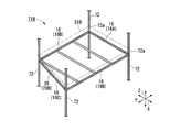
- a beam member 303 is provided between a fire-resistant coated column member 301 and a reduced fire-resistant coated column member 302. It is set to be joined.
- columns and beams provided without reducing the fireproof coating are shown by hatching.
- the fireproof column member 301 is a column member having a fireproof coating.
- the reduced fireproof coated column member 302 is a column member in which the fireproof coating is reduced as compared with the fireproof coated column member 301.
- the plurality of fireproof covered column members 301 and the plurality of reduced fireproof covered column members 302 are arranged side by side in the width direction E1 and the depth direction E2 with an interval therebetween.
- the plurality of fireproof coated column members 301 and the plurality of reduced fireproof coated column members 302 are arranged in a grid as a whole.
- the column members adjacent to the reduced fireproof coated column member 302 in the width direction E1 and the depth direction E2 are arranged so as to be the fireproof coated column member 301.
- the beam member 303 joins the plurality of fire-resistant coated column members 301 and the plurality of reduced fire-resistant coated column members 302 that are arranged in a grid pattern.
- a synthetic slab 304 is provided on the plurality of beam members 303.
- the synthetic slab 304 has concrete, a deck plate, and slab muscles (tensile force transmitting members).
- the deck plate is fixed to the upper surface of the beam member 303 by driving tack bonding, bolt bonding, or the like.
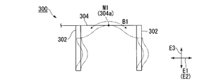
- the fireproof coated column member 301 can maintain rigidity and proof stress not only in a normal time when the outside temperature is room temperature but also in a fire.
- the reduced fireproof coated column member 302 can maintain the rigidity and the proof stress in normal times, but cannot maintain the rigidity and the proof stress in a fire. In the event of a fire, it is considered that the reduced fireproof coated column member 302 loses its rigidity and proof stress.
- the synthetic slab 304 is not shown in FIG.
- the reduced fireproof coating column member 302 and the synthetic slab 304 after deformation are indicated by a two-dot chain line.
- the composite slab 304 arranged on the center line M1 connecting the adjacent fire-resistant coated column members 301 is hereinafter referred to as a line slab 304a.
- the fire-resistant coated column member 301, the reduced fire-resistant coated column member 302, the beam member 303, and the composite slab 304 are affected by gravity not only during normal times but also during a fire.
- the synthetic slab 304 is curved so as to be convex upward with the linear slab 304a as the center.
- the concrete receives a compressive force and the slab muscle receives a tensile force, so that the synthetic slab 304 withstands the bending moment B1.
- the synthetic slab 304 resists gravity acting on the synthetic slab 304 by the bending moment B1.
- the fireproof coating of the reduced fireproof coated column member 302 is smaller than that of the fireproof coated column member 301.
- the robustness of the frame of the refractory structure 300 occurs. Due to this robustness, the composite slab 304 is supported by the fire-resistant coating pillar member 301 in the event of a fire even if the fire-resistant coating of the fire-retardant covering pillar member 302 is reduced.
- a test body including a concrete structure and an explosion-proof fireproof coating layer provided on the surface of the concrete structure is produced. Then, the test body is heated to measure the change in temperature over time, and the relationship between the depth of the test body and the temperature is derived. Based on the relationship, it is determined whether the temperature of the concrete structure is equal to or lower than the heat-resistant allowable temperature. Further, the thickness of the explosion-proof fireproof coating layer is calculated based on the result.
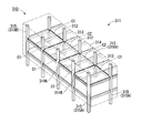
- the slab structure 311 disclosed in Patent Document 3 is used in a building 310.
- the slab structure 311 includes a large beam 312, a steel frame small beam 313, and a slab 314.
- the girders 312 have fire resistance and are bridged between the columns 315.
- the whole or part of the steel beam 313 is not subjected to fireproof coating.
- the steel beam girder 313 is joined to the girder 312.
- the slab 314 is made of reinforced concrete.
- the slab 314 is supported by the large beam 312 and the steel beam small beam 313.
- the pillar 315 located around the slab 314 is defined as an outer pillar 315A.
- the columns other than the outer columns 315A are defined as inner columns 315B.
- a first reference line C1 that passes through the center (for example, the center of gravity) of the inner column 315B and the center of the outer column 315A and reaches the periphery of the slab 314 is defined.
- a second reference line C2 passing through the centers of the inner columns 315B is defined.
- the slab 314 is partitioned into the floor portions 314A, 314B and the like by at least one of the first reference line C1 and the second reference line C2.
- the floor portions 314A, 314B and the like are rectangular in plan view.
- the floor portions 314A, 314B and the like are design sections (design sections) in which the corners do not have a shape chipped by the pillars 315.
- all corners of the floors 314A, 314B and the like are arranged so as to overlap the plurality of columns 315.
- the shape of the floor section partitioned from the slab in plan view means the shape of the floor section partitioned from the slab by the line passing through the center of the column and the periphery of the slab.
- the fire resistant structure disclosed in Patent Document 4 includes a plurality of pillar members, a plurality of girders, girders, and a floor slab. Each girder is installed on a pillar member.
- the plurality of girders have a pair of orthogonal girders provided substantially orthogonal to the girders and a pair of parallel girders provided substantially parallel to the girders.
- a fireproof coating is applied to either one of the cross girders and the parallel girders (hereinafter referred to as the first girder).
- the fireproof coating of the girder and the girder that is either the orthogonal girder or the parallel girder is reduced as compared with the fireproof coating applied to the first girder.
- the cross beam is provided inside the plurality of cross beams.
- the floor slab is provided above the girders and girders.
- the shape of the floor section partitioned from the slab is not specified.
- the floor portion has a rectangular shape in plan view. Amid the diversified configurations of fire-resistant structures, it is desired that the floor can maintain a constant fire resistance even if the floor has a polygonal shape different from a rectangular shape.
- the fire resistance performance of the floor here means to suppress the flexure of the floor during a fire and to prevent the external force from becoming larger than the bending resistance of the floor.
- the present invention has been made in view of such a problem, and a method for designing a refractory structure capable of maintaining a constant fire resistance performance while making the shape of the floor portion a polygonal shape different from a rectangular shape. , A refractory structure construction method, and a refractory structure.
- a first aspect of the present invention is to provide a plurality of refractory-coated columns with a fire-resistant coating, a plurality of fire-resistant coated beams with a fire-resistant coating, which join the plurality of refractory-coated columns to each other, and a tensile force.
- a floor section partitioned from a slab including a transmission member is provided, and in plan view, the fire-resistant coated columns located around the slab among the plurality of fire-resistant coated columns are defined as fire-coated outer columns, Of the plurality of refractory-coated columns, when defining the columns other than the fire-resistant coated outer columns as the fire-resistant coated inner columns, in plan view, the floor portion includes the center of the fire-resistant coated inner columns and the fire-resistant coating.
- a portion of the slab defined by at least one of a first centerline that passes through the center of the coated outer column and reaches the periphery of the slab, and a second centerline that passes through the centers of the refractory coated inner columns.
- the floor portion is formed in a polygonal shape different from a rectangular shape, in a plan view, all corners of the floor portion are arranged so as to overlap the plurality of fireproof coated columns,
- the refractory covered beam is formed in an annular shape as a whole, and the periphery of the floor portion is supported from below by the plurality of refractory covered beams, and a direction intersecting with each other in the plane of the floor portion is a first intersecting direction,
- the tensile force transmitting member includes a tensile force between the end portions of the floor portion in the first intersecting direction and a tensile force between the end portions of the floor portion in the second intersecting direction.
- a method for designing a refractory structure that transmits forces respectively comprising performing the structural calculation to support the slab, a plurality of beams supporting the slab from below, and the plurality of beams.
- the first floor piece partitioned into a predetermined shape in plan view is used as the floor portion, and the floor portion is compressed.
- the main stress of the above, performing a determination step of determining whether or not exceeds a predetermined stress threshold value, in the determination step, the maximum value of the main stress of compression is a part of the periphery of the floor. Occurring in a portion, when it is determined that the maximum value of the principal stress of compression exceeds a predetermined stress threshold value, the floor portion is the first floor piece, and the peripheral portion of the first floor piece.
- the fireproof specification determining step is performed, and the determination step is further performed. You may go.
- a second aspect of the present invention is to provide a plurality of refractory-coated columns with a fire-resistant coating, a plurality of refractory-coated beams for joining the plurality of refractory-coated columns to each other, and a tensile force.
- a floor section partitioned from a slab including a transmission member is provided, and in plan view, the fire-resistant coated columns located around the slab among the plurality of fire-resistant coated columns are defined as fire-coated outer columns, Of the plurality of refractory-coated columns, when defining the columns other than the fire-resistant coated outer columns as the fire-resistant coated inner columns, in plan view, the floor portion includes the center of the fire-resistant coated inner columns and the fire-resistant coating.
- a portion of the slab defined by at least one of a first centerline that passes through the center of the coated outer column and reaches the periphery of the slab, and a second centerline that passes through the centers of the refractory coated inner columns.
- the floor portion is formed in a polygonal shape different from a rectangular shape, in a plan view, all corners of the floor portion are arranged so as to overlap the plurality of fireproof coated columns, Part of the fireproof covered beam and the plurality of fireproof covered columns is formed in an annular shape as a whole, and the periphery of the floor portion is supported from below by the plurality of fireproof covered beams, and is mutually in a plane of the floor portion.
- the tensile force transmitting member includes a tensile force between end portions of the floor portion in the first intersecting direction, and the tensile force of the floor portion.
- a refractory structure design method for designing a refractory structure that transmits tensile forces between ends in the second crossing direction, wherein the slab and a plurality of slabs that support the slab from below are calculated by performing structural calculation.
- a third aspect of the present invention is a refractory structure designed by the method for designing a refractory structure according to any one of (1) to (4).
- a fourth aspect of the present invention is to provide a plurality of fireproof coated columns having a fireproof coating, a plurality of fireproof coated beams for joining the plurality of fireproof coated columns to each other, and a tensile force.
- a floor section partitioned from a slab including a transmission member is provided, and in plan view, the fire-resistant coated columns located around the slab among the plurality of fire-resistant coated columns are defined as fire-coated outer columns, Of the plurality of refractory-coated columns, when defining the columns other than the fire-resistant coated outer columns as the fire-resistant coated inner columns, in plan view, the floor portion includes the center of the fire-resistant coated inner columns and the fire-resistant coating.
- the floor portion is formed in a polygonal shape different from a rectangular shape, in a plan view, all corners of the floor portion are arranged so as to overlap the plurality of fireproof coated columns,
- the refractory covered beam is formed in an annular shape as a whole, and the periphery of the floor portion is supported from below by the plurality of refractory covered beams, and a direction intersecting with each other in the plane of the floor portion is a first intersecting direction,
- the tensile force transmitting member includes a tensile force between the end portions of the floor portion in the first intersecting direction and a tensile force between the end portions of the floor portion in the second intersecting direction.
- a fifth aspect of the present invention is to provide a plurality of fireproof coated columns having a fireproof coating, a plurality of fireproof coated beams which are provided with a fireproof coating, and which join the plurality of fireproof coated columns to each other, and a tensile force.
- a floor section partitioned from a slab including a transmission member is provided, and in plan view, the fire-resistant coated columns located around the slab among the plurality of fire-resistant coated columns are defined as fire-coated outer columns, Of the plurality of refractory-coated columns, when defining the columns other than the fire-resistant coated outer columns as the fire-resistant coated inner columns, in plan view, the floor portion includes the center of the fire-resistant coated inner columns and the fire-resistant coating.
- a portion of the slab defined by at least one of a first centerline that passes through the center of the coated outer column and reaches the periphery of the slab, and a second centerline that passes through the centers of the refractory coated inner columns.
- the floor portion is formed in a polygonal shape different from a rectangular shape, in a plan view, all corners of the floor portion are arranged so as to overlap the plurality of fireproof coated columns, Part of the fireproof covered beam and the plurality of fireproof covered columns is formed in an annular shape as a whole, and the periphery of the floor portion is supported from below by the plurality of fireproof covered beams, and is mutually in a plane of the floor portion.
- the tensile force transmitting member includes a tensile force between end portions of the floor portion in the first intersecting direction, and the tensile force of the floor portion.
- a method for constructing a refractory structure comprising: a coating construction step of forming a part of the plurality of refractory-coated pillars and the plurality of refractory-covered beams, each of which has a fireproof coating on a column, in an annular shape as a whole.
- a sixth aspect of the present invention is to provide a plurality of refractory-coated columns with a fire-resistant coating, a plurality of refractory-coated beams for joining the plurality of refractory-coated columns to each other, and a tensile force.
- a floor section partitioned from a slab including a transmission member is provided, and in plan view, the fire-resistant coated columns located around the slab among the plurality of fire-resistant coated columns are defined as fire-coated outer columns, Of the plurality of refractory-coated columns, when defining the columns other than the fire-resistant coated outer columns as the fire-resistant coated inner columns, in plan view, the floor portion includes the center of the fire-resistant coated inner columns and the fire-resistant coating.
- the floor portion is formed in a polygonal shape different from a rectangular shape, in a plan view, all corners of the floor portion are arranged so as to overlap the plurality of fireproof coated columns,
- the refractory covered beam is formed in an annular shape as a whole, and the periphery of the floor portion is supported from below by the plurality of refractory covered beams, and a direction intersecting with each other in the plane of the floor portion is a first intersecting direction,
- the tensile force transmitting member includes a tensile force between the end portions of the floor portion in the first intersecting direction and a tensile force between the end portions of the floor portion in the second intersecting direction. It is a fire-resistant structure that
- the refractory coating is reduced more than the refractory coated beam, and the end portion is arranged in a region surrounded by the annular fireproof coated beams.
- a reduced fire resistant coated beam may be provided that is joined to the plurality of fire resistant coated beams and supports the floor portion from below.
- the fire resistant coated beam may not be joined to a portion other than the periphery of the floor portion.
- the floor for a desired heating time when heated according to a heating curve defined in ISO 834-11:2014.
- the maximum value of the bending of the part may be less than the threshold value K(m) defined by the equation (1).
- K (L+1)/30 ⁇ (1)
- L is the length (m) of the first span along the plane of the floor
- l is the length (m of the second span along the plane of the floor and intersecting the first span. ).
- a seventh aspect of the present invention is to provide a plurality of refractory-coated columns with a fire-resistant coating, a plurality of refractory-coated beams for joining the plurality of refractory-coated columns to each other, and a tensile force.
- a floor section partitioned from a slab including a transmission member is provided, and in plan view, the fire-resistant coated columns located around the slab among the plurality of fire-resistant coated columns are defined as fire-coated outer columns, Of the plurality of refractory-coated columns, when defining the columns other than the fire-resistant coated outer columns as the fire-resistant coated inner columns, in plan view, the floor portion includes the center of the fire-resistant coated inner columns and the fire-resistant coating.
- a portion of the slab defined by at least one of a first centerline that passes through the center of the coated outer column and reaches the periphery of the slab, and a second centerline that passes through the centers of the refractory coated inner columns.
- the floor portion is formed in a polygonal shape different from a rectangular shape, in a plan view, all corners of the floor portion are arranged so as to overlap the plurality of fireproof coated columns, Part of the fireproof covered beam and the plurality of fireproof covered columns is formed in an annular shape as a whole, and the periphery of the floor portion is supported from below by the plurality of fireproof covered beams, and is mutually in a plane of the floor portion.
- the tensile force transmitting member When the intersecting direction is defined as a first intersecting direction and a second intersecting direction, the tensile force transmitting member includes a tensile force between end portions of the floor portion in the first intersecting direction, and the tensile force of the floor portion.
- the refractory structure transmits tensile forces between the ends in the second intersecting direction.
- the periphery of the floor portion has a plurality of fireproof elements formed in an annular shape that can maintain constant rigidity and yield strength even in the event of a fire. It is set to be supported from below by the covered beam. At this time, the floor is set to have a polygonal shape different from a rectangular shape in a plan view by at least one of the first centerline and the second centerline. All of the corners of the floor portion are set so as to overlap the plurality of fireproof covered columns in a plan view, so that all the corners are supported by the plurality of fireproof covered columns.
- the tensile force transmitting member included in the floor portion transmits the tensile force between the end portions of the floor portion in the first intersecting direction and the tensile force between the end portions of the floor portion in the second intersecting direction.
- the center of the floor in a plan view is bent downward so as to be convex.
- the perimeter of the floor is supported by the fireproof beam.
- the tensile force transmitting member extended by the bending of the floor portion transmits the tensile force in each of the first intersecting direction and the second intersecting direction, so that the central portion of the floor portion is supported. Therefore, even if the shape of the floor portion is different from the rectangular shape, it is possible to set the refractory structure to maintain a constant fire resistance performance.
- a plurality of fireproofs formed in an annular shape that can maintain a certain rigidity and yield strength around the floor by performing the pillar-beam construction process and the covering construction process even in the event of a fire. It is supported from below by a covered beam.
- the floor is formed in a polygonal shape different from a rectangular shape in plan view by at least one of the first centerline and the second centerline. All of the corners of the floor portion are overlapped with the plurality of fireproof covered columns in a plan view, so that all the corners are supported by the plurality of fireproof covered columns.
- the tensile force transmitting member included in the floor portion transmits the tensile force between the end portions of the floor portion in the first intersecting direction and the tensile force between the end portions of the floor portion in the second intersecting direction.
- the center of the floor in a plan view is bent downward so as to be convex.
- the perimeter of the floor is supported by the fireproof beam.
- the tensile force transmitting member extended by the bending of the floor portion transmits the tensile force in each of the first intersecting direction and the second intersecting direction, so that the central portion of the floor portion is supported. Therefore, even if the shape of the floor portion is different from the rectangular shape, it is possible to maintain the fireproof structure with a constant fireproof performance.
- the periphery of the floor portion is supported from below by a plurality of fireproof covered beams formed in an annular shape that can maintain constant rigidity and proof stress even in the event of a fire.
- the floor portion is formed in a polygonal shape different from a rectangular shape in plan view. All of the corners of the floor portion are overlapped with the plurality of fireproof covered columns in a plan view, so that all the corners are supported by the plurality of fireproof covered columns.
- the tensile force transmitting member included in the floor portion transmits the tensile force between the end portions of the floor portion in the first intersecting direction and the tensile force between the end portions of the floor portion in the second intersecting direction.
- the center of the floor in a plan view is bent downward so as to be convex.
- the perimeter of the floor is supported by the fireproof beam.
- the tensile force transmitting member extended by the bending of the floor portion transmits the tensile force in each of the first intersecting direction and the second intersecting direction, so that the central portion of the floor portion is supported. Therefore, even if the shape of the floor portion is different from the rectangular shape, it is possible to maintain the fireproof structure with a constant fireproof performance.
- a constant rigidity and yield strength can be maintained around the floor even in the event of a fire, and a ring shape is formed as a whole.
- the plurality of refractory-covered beams and a part of the plurality of refractory-covered columns are set to be supported from below.
- the floor is set to have a polygonal shape different from a rectangular shape in a plan view by at least one of the first centerline and the second centerline. All of the corners of the floor portion are set so as to overlap the plurality of fireproof covered columns in a plan view, so that all the corners are supported by the plurality of fireproof covered columns.
- the tensile force transmitting member included in the floor portion transmits the tensile force between the end portions of the floor portion in the first intersecting direction and the tensile force between the end portions of the floor portion in the second intersecting direction.
- the center of the floor in a plan view is bent downward so as to be convex.
- the perimeter of the floor is supported by the fireproof beam.
- the tensile force transmitting member extended by the bending of the floor portion transmits the tensile force in each of the first intersecting direction and the second intersecting direction, so that the central portion of the floor portion is supported. Therefore, even if the shape of the floor portion is different from the rectangular shape, it is possible to set the refractory structure to maintain a constant fire resistance performance.
- the floor is formed in a polygonal shape different from a rectangular shape in plan view by at least one of the first centerline and the second centerline. All of the corners of the floor portion are overlapped with the plurality of fireproof covered columns in a plan view, so that all the corners are supported by the plurality of fireproof covered columns.
- the tensile force transmitting member included in the floor portion transmits the tensile force between the end portions of the floor portion in the first intersecting direction and the tensile force between the end portions of the floor portion in the second intersecting direction.
- the center of the floor in a plan view is bent downward so as to be convex.
- the perimeter of the floor is supported by the fireproof beam.
- the tensile force transmitting member extended by the bending of the floor portion transmits the tensile force in each of the first intersecting direction and the second intersecting direction, so that the central portion of the floor portion is supported. Therefore, even if the shape of the floor portion is different from the rectangular shape, it is possible to maintain the fireproof structure with a constant fireproof performance.
- the periphery of the floor portion can maintain a certain rigidity and proof stress even in the event of a fire, and one of the plurality of fireproof covered beams and the plurality of fireproof covered columns that are formed in an annular shape as a whole. Supported from below.
- the floor portion is formed in a polygonal shape different from a rectangular shape in plan view. All of the corners of the floor portion are overlapped with the plurality of fireproof covered columns in a plan view, so that all the corners are supported by the plurality of fireproof covered columns.
- the tensile force transmitting member included in the floor portion transmits the tensile force between the end portions of the floor portion in the first intersecting direction and the tensile force between the end portions of the floor portion in the second intersecting direction.
- the center of the floor in a plan view is bent downward so as to be convex.
- the perimeter of the floor is supported by the fireproof beam.
- the tensile force transmitting member extended by the bending of the floor portion transmits the tensile force in each of the first intersecting direction and the second intersecting direction, so that the central portion of the floor portion is supported. Therefore, even if the shape of the floor portion is different from the rectangular shape, it is possible to maintain the fireproof structure with a constant fireproof performance.
- the principal stress of compression of the floor may not exceed the stress threshold in the determination step, for example. In such a case, the structure of the refractory structure in which the principal stress of compression of the floor does not exceed the stress threshold can be set in a short time.
- the fire resistant structure can be designed by the method for designing a fire resistant structure according to the present invention.
- the method for designing a refractory structure of the present invention is a method capable of maintaining a constant fire resistance performance while making the shape of the floor portion a polygonal shape different from a rectangular shape.
- the method for designing a refractory structure, the method for constructing a refractory structure, and the refractory structure of the present invention it is possible to maintain a constant fire resistance performance while making the shape of the floor part a polygonal shape different from a rectangular shape. .
- FIG. 2 is a sectional view taken along the section line A1-A1 in FIG. 1. It is a top view which shows the 1st modification of the 1st rebar of the same refractory structure. It is a top view which shows the 2nd modification of the 1st rebar of the same refractory structure. It is a top view showing the 3rd modification of the 1st rebar of the same refractory structure. It is a top view which shows the 4th modification of the 1st rebar of the same refractory structure.
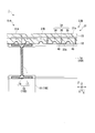
- FIG. 2 is a cross-sectional view taken along the section line A2-A2 in FIG. 1.
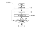
- It is a flowchart which shows the design method of the fireproof structure of 1st Embodiment of this invention. It is a perspective view explaining the structure determination process in the design method of the same refractory structure. It is a perspective view explaining the fireproof specification deciding process in the design method of the fireproof structure. It is a perspective view explaining the structure determination process in the design method of the same refractory structure. It is a perspective view explaining the fireproof specification deciding process in the design method of the fireproof structure. It is an exploded perspective view of the fireproof structure for explaining external force which usually acts on the fireproof structure.
- FIG. 32 is a cross-sectional view taken along the section line A11-A11 in FIG. It is a perspective view of the conventional building.
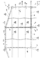
- the building 1 includes a plurality of fireproof coated columns 11, a plurality of fireproof coated beams 16, a plurality of reduced fireproof coated beams 26, and a floor (slab) 31. ing.
- the refractory-coated columns 11 and the refractory-coated beams 16 are shown by hatching.
- each refractory-coated pillar 11 extends in the up-down direction Z.
- the plurality of refractory covered columns 11 are arranged side by side with a space therebetween in a first intersecting direction X and a second intersecting direction Y which are orthogonal to the vertical direction Z and are orthogonal (intersecting) to each other.
- the fireproof coated columns 11 located around the floor 31 are also called (defining) outer columns 11A that are fireproof coated.
- outer columns 11A that are fireproof coated.
- other than the fireproof coated outer pillars 11A are also referred to as fireproof coated inner pillars 11B.
- the fire-resistant coated inner pillar 11B is the fire-resistant covered pillar 11 located in the center of the floor 31 in a plan view.
- a part of the plurality of fire-resistant coated outer pillars 11A (hereinafter, also referred to as the fire-resistant coated outer pillars 11A1) is arranged so as to be displaced in the second intersecting direction Y from the position aligned in the first intersecting direction X. There is.
- the fireproof coated beam 16 is an H-shaped steel 18 provided with a fireproof coating 17.
- a heat insulating material such as rock wool or glass wool is used for the fireproof coating 17.
- the fireproof coating 17 is formed on the outer surface of the H-shaped steel 18 by various methods such as spraying, painting, forming plate, and winding.
- the refractory-covered beam 16 is formed in a linear shape and is arranged along a horizontal plane. Both ends of the fireproof coated beam 16 are joined to the other fireproof coated beam 16 and the fireproof coated column 11, respectively.
- the fireproof covered beam 16 joins the plurality of fireproof covered columns 11 to each other. As shown in FIG.
- a fireproof covered beam 16A which is a part of the plurality of fireproof covered beams 16, extends along the first intersecting direction X.
- a fireproof covered beam 16B which is another part of the plurality of fireproof covered beams 16, extends along the second intersecting direction Y.
- the refractory covered beams 16C which are the rest of the plurality of refractory covered beams 16, have their ends joined to the refractory covered beams 16A and 16B, respectively, and are inclined with respect to the first cross direction X and the second cross direction Y, respectively. There is.
- a plurality of fireproof covered beams 16 such as a fireproof covered beam 16C, a fireproof covered beam 16A, and two fireproof covered beams 16B constitute a fireproof covered beam aggregate 16D.
- the refractory-covered beam assembly 16D is formed in a ring shape (ring, square ring shape) that is a trapezoidal frame in plan view as a whole.
- the plurality of fireproof coated beams 16 are supported from below by the plurality of fireproof coated columns 11. RC and SRC may be used for the fireproof coated beam 16.
- the reduced fireproof coated beam 26 is a beam having a reduced fireproof coating than the fireproof coated beam 16.
- the reduced fireproof coated beam 26 may be H-section steel that is not provided with a fireproof coating.
- the reduced refractory coated beam 26 may be H-section steel with some refractory coating, although it has less refractory coating than the refractory coated beam 16.
- the thickness of the fire-resistant coating such as rock wool on the fire-resistant coated beam 16 is set in accordance with the "Blow-up rock wool-coated fire resistant structure construction quality control guideline (Rock Wool Industry Association Spraying Section)". When the fireproof coating beam 16 is required to be fireproof for one hour, the thickness of the fireproof coating is set to 25 mm.
- the thickness of the fireproof coating is set to 45 mm and when fireproof is required for 3 hours, the thickness is set to 65 mm.
- the thickness of the fireproof coating in the reduced fireproof coated beam 26 is set to about 1/10 to 1/2 of the thickness of the fireproof coating in the fireproof coated beam 16 corresponding to each fireproof performance.
- the reduced fireproof coated beam 26 is arranged in a region R1 or the like surrounded by the fireproof coated beam assembly 16D. Both ends of the reduced fireproof coated beam 26 are joined to the plurality of fireproof coated beams 16.
- the floor 31 is a so-called synthetic slab, and is supported from below by a plurality of fireproof covered beams 16 and a plurality of reduced fireproof covered beams 26.
- the floor 31 includes a deck plate (tensile force transmitting member) 32, concrete 33, and reinforcing bars (tensile force transmitting member) 34.
- the floor 31 may not include the deck plate 32 and the concrete 33.
- the floor 31 may not include the reinforcing bar 34 and the concrete 33.
- the tensile force transmission member included in the floor 31 is not limited to the deck plate 32 and the reinforcing bar 34.
- the deck plate 32 is formed by bending a steel plate.
- the deck plate 32 is disposed on the plurality of fireproof coated beams 16 and the plurality of reduced fireproof coated beams 26.
- the concrete 33 is formed in a plate shape in which the vertical direction Z is the thickness direction.
- the concrete 33 is formed with a convex portion 33 a protruding downward corresponding to the shape of the deck plate 32.
- the width of the convex portion 33a in the first intersecting direction X gradually becomes smaller as it goes downward.
- the reinforcing bar 34 is embedded in the concrete 33.
- the reinforcing bar 34 includes a plurality of first reinforcing bars 35 and a plurality of second reinforcing bars 36. Note that only one first reinforcing bar 35 is shown in FIG. 2.
- Each first reinforcing bar 35 extends along the first intersecting direction X.
- Each first rebar 35 transmits a tensile force between the ends of the concrete 33 (floor 31) in the first cross direction X. That is, each first rebar 35 extends between the first end of the concrete 33 in the first intersecting direction X and the second end of the concrete 33 opposite to the first end in the first intersecting direction X. It is extended.
- each first rebar 35 transmits the tensile force acting between the first end and the second end of the concrete 33 between the first end and the second end of the concrete 33.
- the plurality of first reinforcing bars 35 are arranged at intervals in the second intersecting direction Y.
- each second reinforcing bar 36 extends along the second intersecting direction Y.
- Each second rebar 36 transmits a tensile force between the ends of the concrete 33 in the second cross direction Y.
- the plurality of second reinforcing bars 36 are arranged at intervals in the first intersecting direction X.
- the direction in which the reinforcing bars 35 and 36 extend may differ from the direction in which the plurality of refractory-coated columns 11 are arranged side by side with an interval therebetween.
- the details of the configurations of the first reinforcing bar 35 and the second reinforcing bar 36 will be described by taking the first reinforcing bar 35 as an example.
- the first reinforcing bar 35 is not particularly limited as long as it can transmit the tensile force between the ends of the concrete 33 in the first intersecting direction X.
- the first reinforcing bar 35 may be formed of one reinforcing bar between the first end portion and the second end portion of the concrete 33 in the first intersecting direction X, but may be configured as follows.
- the first reinforcing bar 35 round steel, deformed bar steel, welded gold steel or the like is used.
- the first reinforcing bar 35A may include reinforcing bar pieces 37a and 37b and a connecting reinforcing bar 37c that connects end portions of the reinforcing bar pieces 37a and 37b.
- the reinforcing bar pieces 37a and 37b and the connecting reinforcing bar 37c are made of the same material as that of the first reinforcing bar 35.
- the end of the reinforcing bar piece 37a and the first end of the connecting reinforcing bar 37c are joined by a welded portion 38 formed by welding.
- the welded portion 38 joins the end of the rebar piece 37b and the second end of the connecting rebar 37c opposite to the first end.
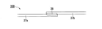
- the first reinforcing bar 35B may include a reinforcing bar piece 37a and a reinforcing bar piece 37b.
- the end of the rebar piece 37a and the end of the rebar piece 37b are joined by a welded portion 38.
- the first reinforcing bar 35C may include reinforcing bar pieces 37a and 37b and a wire (wire) 39.
- the reinforcing bar piece 37a and the reinforcing bar piece 37b are connected by a number wire 39 in a state of being overlapped with each other by a predetermined required length.
- the rebar piece 37a and the rebar piece 37 are joined to each other by bonding.
- the 1st reinforcing bar 35D may be provided with reinforcing bar pieces 37a and 37b, and mechanical joint 40.
- the mechanical joint 40 is a coupling or the like.
- the mechanical joint 40 joins the reinforcing bar pieces 37a and 37b by sandwiching the ends of the reinforcing bar pieces 37a and 37b, respectively.
- the second reinforcing bar 36 is configured similarly to the first reinforcing bar 35.
- a bent portion 35a bent downward may be formed at an end portion of the first reinforcing bar 35 in the first intersecting direction X.
- the bent portion 35a extends downward from the outer side of the second rebar 36 located on the outermost side in the first intersecting direction X among the plurality of second rebars 36.
- the number of the first reinforcing bars 35 included in the reinforcing bars 34 is not particularly limited and may be one.
- the number of the second reinforcing bars 36 included in the reinforcing bars 34 is not particularly limited and may be one.
- the first intersecting direction X and the second intersecting direction Y are directions that intersect with each other within a plane 31 a that is the upper surface of the floor 31.
- the floor 31 includes the studs 46 and the like provided on the upper surfaces of the plurality of fireproof covered beams 16 and the plurality of reduced fireproof covered beams 26 and the plurality of fireproof covered beams 16 and the plurality of reduced fireproof covered beams 26. It is fixed to.
- the H-shaped steel 18 of the fireproof coated beam 16 is configured by joining an upper flange 18a and a lower flange 18b to each other via a web 18c.
- the edge of the upper flange 18a of the H-section steel 18 on the central portion side of the floor 31 in plan view is referred to as an edge 18a1.
- An edge of the upper flange 18a opposite to the edge 18Aa1 is referred to as an edge 18a2.
- the center of the web 18c in the first intersecting direction X is referred to as a plate center 18c1.
- the edge of the concrete 33 in the first intersecting direction X coincides with the edge 18a2.
- the end of the first reinforcing bar 35 in the first intersecting direction X reaches the end edge 18a1 from the central portion side of the floor 31 in plan view. More preferably, this end portion of the first reinforcing bar 35 reaches the plate center 18c1 in the first intersecting direction X.
- the positional relationship between the first reinforcing bars 35 and the second reinforcing bars 36 of the floor 31 and the fireproof coated beam 16 is such that the first reinforcing bars 35 and the second reinforcing bars 36 and the fireproofing included in floor sections 31A and 31B described below that are partitioned from the floor 31 and fireproof. This is similar to the positional relationship with the covered beam 16.
- the first center line C6 and the second center line C7 are defined with reference to FIG.
- the first center line C6 is a line (line segment) that passes through the center of the inner pillar 11B covered with fireproof and the center of the outer pillar 11A covered with fireproof to reach the periphery of the floor 31 in a plan view.
- the center of the column referred to here is, for example, the center of gravity of the column in a plan view.
- the first end of the first centerline C6 is located at the center of the fireproof coated inner pillar 11B.
- a second end of the first centerline C6 opposite to the first end is located around the floor 31.
- the first centerline C6 passes through the center of the fire-resistant coated outer pillar 11A.
- the second centerline C7 is a line (line segment) that passes through the centers of the inner pillars 11B that are fireproof coated in plan view.
- the first end of the second centerline C7 is located at the center of one of the pair of fireproof coated inner pillars 11B.
- a second end of the second centerline C7, which is opposite to the first end, is located at the center of the other of the pair of fireproof coated inner pillars 11B.
- the floor 31 is divided into a plurality of floor portions 31A and 31B by at least one of the first center line C6 and the second center line C7 and the periphery of the floor 31.
- Floors 31A and 31B are a part of floor 31 partitioned from floor 31.
- the floor 31 may be partitioned by at least one of the first center line C6 and the second center line C7.
- the floor 31 is partitioned into a first floor portion 31A by two first center lines C6 and one second center line C7.
- the floor 31 is divided into a second floor portion (floor portion) 31B by two first center lines C6.
- Floors 31A and 31B are a part of floor 31 divided by at least one of center lines C6 and C7.
- the refractory covered beam assembly 16E is formed in an annular shape as a whole in a plan view.
- the first floor portion 31A is partitioned into a rectangular shape in plan view corresponding to the fireproof coated beam aggregate 16E.
- the circumference of the first floor portion 31A is supported from below by the fire-resistant covered beam assembly 16E over the entire circumference.
- all corners of the first floor portion 31A are arranged so as to overlap the plurality of fireproof coated columns 11.
- the term "a corner overlaps with the plurality of fireproof coated columns 11" means that at least a part of the corner is arranged in an area occupied by at least one of the plurality of fireproof coated columns. All the corners of the first floor portion 31A are supported from below by any of the plurality of fireproof coated columns 11.
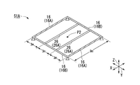
- the first floor 31A, the four fireproof covered columns 11, the fireproof covered beam assembly 16E, and the reduced fireproof covered beam 26A supporting the first floor 31A among the plurality of reduced fireproof covered beams 26 provide a first fireproof structure.
- the object 51A is configured.
- the second floor portion 31B is formed in a polygonal shape different from the rectangular shape in a plan view, corresponding to the fireproof covered beam assembly 16D. More specifically, the polygonal shape is trapezoidal.
- the reinforcing bar 34 included in the second floor portion 31B is a tensile force between the end portions of the second floor portion 31B in the first intersecting direction X, and a tensile force between the end portions of the second floor portion 31B in the second intersecting direction Y. Transmit power respectively.
- the second floor 31B, the four fireproof coated columns 11, the fireproof coated beam aggregate 16D, and the reduced fireproof coated beam 26B that supports the second floor 31B among the plurality of reduced fireproof coated beams 26 provide a second fireproof structure.
- the object (fireproof structure) 51B is configured. In FIG. 2, the boundary between the first refractory structure 51A and the second refractory structure 51B is indicated by a solid line.
- the periphery of the second floor portion 31B is supported from below by the fire-resistant covered beam assembly 16D over the entire circumference.
- all corners of the second floor portion 31B are arranged so as to overlap the plurality of fireproof coated columns 11. That is, all the corners of the second floor portion 31B are supported from below by any of the plurality of fireproof coated columns 11.
- the second refractory structure 51B includes three reduced fireproof coated beams 26B. No other refractory covered pillars 11 are arranged inside the four refractory covered pillars 11 constituting the second refractory structure 51B.
- the refractory-covered beam 16 is not joined to a portion other than the periphery of the second floor portion 31B.
- the beams arranged inside the fireproof covered beams 16A, 16B, and 16C that are joined all around the second floor portion 31B are the reduced fireproof covered beams 26.
- the reduced fireproof coating beam 26 supports the second floor portion 31B from below.
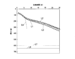
- the heating curve defined by ISO 834-11:2014 (hereinafter abbreviated as ISO 834) is also simply referred to as a heating curve below.
- L and l are lengths in the direction along the flat surface 31a of the second floor portion 31B.
- This threshold value K is the floor bending limit value described in Non-Patent Document 1 described above.
- the first span is not limited to the length in the first intersecting direction X, and may be any length in the direction within the plane 31a of the second floor 31B (direction along the plane 31a).
- the second span is not limited to the length in the second intersecting direction Y, and may be a direction within the plane 31a of the second floor portion 31B and a length orthogonal to (crossing) the first span. Good.
- L is the length of the first span along the plane of the second floor
- l is along the plane of the floor and intersects the first span. It is the length of the second span.
- FIG. 8 is a flowchart showing the design method S of this embodiment.
- a design method for designing the second refractory structure 51B of the building 1 will be described.
- This design method S is preferably used for, for example, a newly constructed second refractory structure 51B and an existing second refractory structure 51B.
- a stress threshold value is determined in advance. For example, the stress threshold value is determined based on the design criteria of the material used for the second refractory structure 51B.
- step S1 ends, the process moves to step S3.
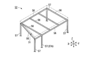
- step S3 a well-known structure calculation is performed to determine the arrangement of the floor 31, the plurality of beams 56, and the plurality of columns 57 in the structure 52, as shown in FIG. To do.
- the floor 31 is shown by a two-dot chain line.
- the beam 56 is a beam obtained by removing the fireproof coating from the fireproof coated beam 16 and the reduced fireproof coated beam 26.
- the plurality of beams 56 support the floor 31 from below.
- the pillar 57 is a pillar obtained by removing the fireproof coating from the fireproof coated pillar 11.
- the plurality of columns 57 support the plurality of beams 56.
- the structure 52 includes one more column 57 (the fire-resistant coated column 11) than the second refractory structure 51B (hereinafter, also referred to as column 57A).
- the pillars 57A are arranged so as to overlap with the three pillars 57 of the plurality of pillars 57 that the structure 52 already has, and to overlap each corner of a predetermined rectangular shape in a plan view.
- the pillar 57A is arranged in the vicinity of the end of the beam 56 that becomes the plurality of reduced fireproof coated beams 26.
- the specifications and arrangement of the plurality of beams 56 and the plurality of columns 57 are determined based on the weight of the floor 31 and the load acting on the floor 31.
- step S5 when the second floor 31B1 is partitioned from the floor 31, the following settings are made.
- the periphery of the second floor portion 31B1 partitioned from the floor 31 is set so as to be supported from below by the plurality of fireproof covered beams 16 in which the beams 56 are fireproof coated.
- the division of the floor 31 is performed using the first centerline C6.
- the plurality of refractory covered beams 16 are formed in an annular shape as a whole. All corners included in the second floor portion 31B1 are set so as to be arranged so as to overlap the plurality of fireproof coated columns 11.
- the first floor piece 31C partitioned in a rectangular shape (predetermined shape) in plan view is used as the second floor portion 31B1.
- the second refractory structure 51B1 is designed by applying a fireproof coating to at least a part of the plurality of beams 56 so that the membrane effect by the second floor portion 31B1 is exhibited in the event of a fire.
- the membrane effect referred to here is the shape in which the floor on which a load acts in the event of a fire is bent so that the center of the floor becomes convex downward due to the fire-resistant coated beam and the tensile force transmission member. Means the effect of holding.
- the periphery of the second floor portion 31B1 is set so as to be supported from below by the plurality of fireproof covered beams 16 formed in an annular shape as a whole. All corners included in the second floor portion 31B1 are set so as to be arranged so as to overlap the plurality of fireproof coated columns 11.
- a fireproof coating to a part of the beam 56 in the longitudinal direction, a fireproof coated beam 16B and a beam piece 56A are formed from the beam 56.
- step S7 it is determined whether the main compressive stress of the second floor portion 31B1 exceeds the stress threshold value. Whether or not the main stress of compression of the second floor portion 31B1 exceeds the stress threshold value can be determined by performing a known simulation or the like.
- the process proceeds to the structure determination step S3.
- the principal stress of compression of the second floor portion 31B1 does not exceed the stress threshold value (is equal to or less than the stress threshold value) (NO)
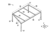
- the arrangement of the floor 31, the plurality of beams 56, and the plurality of columns 57 in the structure 52A is determined.
- the structure 52A does not include the column 57A with respect to the structure 52.
- the fireproof specification determining step S5 as shown in FIG. 12, it is assumed that the second floor portion 31B is partitioned into a shape including a first floor piece 31C and a second floor piece 31D.
- the second floor piece 31D is continuous with the peripheral portion 31C1 of the first floor piece 31C.
- the second floor piece 31D has a triangular shape in a plan view.
- the second floor portion 31B has a trapezoidal shape in a plan view.
- the periphery of the second floor portion 31B partitioned from the floor 31 is set so as to be supported from below by the plurality of fireproof covered beams 16 in which the beams 56 are fireproof coated.
- the plurality of refractory covered beams 16 are formed in an annular shape as a whole. All the corners included in the second floor portion 31B are set so as to be arranged so as to overlap the plurality of fireproof coated columns 11.
- the determination step S7 it is determined whether or not the principal stress of compression of the second floor portion 31B exceeds the stress threshold value. Generally, if the floor portion is provided with the second floor piece connected to the peripheral portion, the maximum value of the principal stress of compression generated in the peripheral portion is likely to be relaxed. In this example, in the determination step S7, it is determined that the main stress of compression of the second floor portion 31B does not exceed the stress threshold value (NO), and all steps of the design method S are completed.
- the second refractory structure 51B is a refractory structure designed by the design method S.
- the fireproof specification determining step S5 may be performed. Further, in the design method of the present embodiment, it may be assumed that the second floor has a polygonal shape different from a rectangular shape in plan view in the fireproof specification determining step. Even in this case, if it is determined in the determination step that the principal stress of compression of the floor does not exceed the stress threshold value (NO), all steps of the design method are completed.
- FIG. 13 shows an exploded perspective view of the second refractory structure 51B in a normal state where no fire has occurred. Note that, in FIG. 13 and FIG. 14 described later, the second refractory structure 51B is shown in a simplified manner. Specifically, FIGS. 13 and 14 show only one reduced fireproof coated beam 26 of the second refractory structure 51B. In the normal state shown in FIG. 13, a downward external force F1 acts on the second floor portion 31B, the reduced fireproof coating beam 26, and the like due to gravity, static load, and the like acting on the second floor portion 31B, the reduced fireproof coating beam 26, and the like.
- the central portion of the second floor portion 31B in plan view bends downward to be convex.
- the periphery of the second floor portion 31B is supported by the plurality of fireproof covered beams 16 formed in an annular shape as a whole.
- the first rebar 35 extended by the bending of the second floor portion 31B transmits the tensile force F2 in the first intersecting direction X.
- the second reinforcing bar 36 that is extended by the bending of the second floor portion 31B transmits the tensile force F3 in the second intersecting direction Y.
- the second floor portion 31B resists gravity or the like acting on the second floor portion 31B by the tensile forces F2 and F3. Therefore, the central portion of the second floor portion 31B is supported by the plurality of fireproof covered beams 16 and the reinforcing bars 35 and 36 in the first intersecting direction X and the second intersecting direction Y, respectively.
- the tensile region R5 and the compression region R6 are respectively formed on the second floor portion 31B.
- the compression region R6 is shown with hatching in FIG. In the pulling region R5, the second floor portion 31B is pulled along the bent flat surface 31a. In the compression region R6, the second floor portion 31B is compressed along the bent flat surface 31a.
- the tensile region R5 is formed in the central portion of the second floor portion 31B in plan view.
- the compression region R6 is formed around the tension region R5.
- the membrane effect generated in the second refractory structure 51B at the time of fire is an effect of resisting the tensile forces F2 and F3 by the reinforcing bars 34.
- the robustness that occurs in the refractory structure at the time of fire is the effect of resisting the bending moment B1 by the concrete and the slab reinforcement.
- the second refractory structure 51B of the present embodiment and the refractory structure of Patent Document 1 have different effects that occur during a fire.
- FIG. 15 is a flowchart which shows the construction method S20 of this embodiment. While each step of the design method S is set but not actually executed, the difference is that each step of the installation method S20 is actually executed.
- This construction method S20 is preferably used, for example, for the second refractory structure 51B to be newly constructed.
- a column and beam construction step S21 and a covering construction step S23 are performed.
- the column-beam construction step S21 the floor 31, the plurality of beams 56, and the plurality of columns 57 are constructed.
- the covering construction step S23 at least a part of the plurality of beams 56 is provided with a fireproof coating to form a plurality of fireproof coated beams 16, so that the periphery of the second floor portion 31B is supported from below by the plurality of fireproof coated beams 16.
- Non-Patent Document 1 In the method for designing a refractory structure disclosed in Non-Patent Document 1, the floor is designed to have a rectangular shape in plan view. For this reason, those skilled in the art who have seen Non-Patent Document 1 try to exert the membrane effect even when the shape is rectangular.
- the design method S of the present embodiment by performing the structure determining step S3 and the fireproof specification determining step S5, the surroundings of the second floor portion 31B maintain constant rigidity and proof stress even during a fire. It is set so as to be supported from below by a plurality of refractory-covered beams 16 formed in an annular shape. At this time, the two first center lines C6 set the second floor portion 31B to be trapezoidal in plan view. All of the corners of the second floor portion 31B are set so as to overlap the plurality of fireproof coated columns 11 in a plan view, so that all the corners are supported by the plurality of fireproof coated columns 11.
- the reinforcing bars 34 included in the second floor portion 31B are the tensile force F2 between the ends of the second floor portion 31B in the first intersecting direction X and the end portion of the second floor portion 31B in the second intersecting direction Y.
- the tensile force F3 between them is transmitted.
- the center portion of the second floor portion 31B in a plan view is bent downward so as to be convex.
- the periphery of the second floor portion 31B is supported by the fireproof coated beam 16.
- the reinforcing bar 34 extended by the bending of the second floor portion 31B transmits the tensile forces F2 and F3 in the first intersecting direction X and the second intersecting direction Y, respectively, so that the central portion of the second floor portion 31B is moved. Supported. Therefore, even if the second floor portion 31B has a trapezoidal shape, the second fire resistant structure 51B can be set to maintain a constant fire resistant performance.
- the circumference of the second floor portion 31B is formed into an annular shape that can maintain constant rigidity and proof stress even in the event of a fire. It is supported from below by the formed plurality of refractory covered beams 16. At this time, the second floor portion 31B is formed in a trapezoidal shape in a plan view by the two first center lines C6. All of the corners of the second floor portion 31B overlap with the plurality of fireproof coated columns 11 in a plan view, so that all the corners are supported by the plurality of fireproof coated columns 11.
- the reinforcing bars 34 included in the second floor portion 31B are the tensile force F2 between the ends of the second floor portion 31B in the first intersecting direction X and the end portion of the second floor portion 31B in the second intersecting direction Y.
- the tensile force F3 between them is transmitted.
- the center portion of the second floor portion 31B in a plan view is bent downward so as to be convex.
- the periphery of the second floor portion 31B is supported by the fireproof coated beam 16.
- the reinforcing bar 34 extended by the bending of the second floor portion 31B transmits the tensile forces F2 and F3 in the first intersecting direction X and the second intersecting direction Y, respectively, so that the central portion of the second floor portion 31B is moved. Supported. Therefore, even if the shape of the second floor portion 31B is trapezoidal, the second refractory structure 51B can be maintained at a constant fire resistance performance.
- the periphery of the second floor portion 31B is provided from below by a plurality of fire-resistant coated beams 16 formed in an annular shape that can maintain constant rigidity and proof strength even in the event of a fire. Supported.
- the two first center lines C6 form the second floor portion 31B in a trapezoidal shape in a plan view. All of the corners of the second floor portion 31B overlap with the plurality of fireproof coated columns 11 in a plan view, so that all the corners are supported by the plurality of fireproof coated columns 11.
- the reinforcing bars 34 included in the second floor portion 31B are the tensile force F2 between the ends of the second floor portion 31B in the first intersecting direction X and the end portion of the second floor portion 31B in the second intersecting direction Y.
- the tensile force F3 between them is transmitted.
- the center portion of the second floor portion 31B in a plan view is bent downward so as to be convex.
- the periphery of the second floor portion 31B is supported by the fireproof coated beam 16.
- the reinforcing bar 34 extended by the bending of the second floor portion 31B transmits the tensile forces F2 and F3 in the first intersecting direction X and the second intersecting direction Y, respectively, so that the central portion of the second floor portion 31B is moved. Supported. Therefore, even if the shape of the second floor portion 31B is trapezoidal, the second refractory structure 51B can be maintained at a constant fire resistance performance.
- the second refractory structure 51B includes the reduced fire resistant coating beam 26. Therefore, it is possible to prevent the second floor portion 31B from bending during a normal time when no fire occurs.
- the refractory-covered beam 16 is not joined to a portion other than the periphery of the second floor portion 31B. Therefore, it is possible to prevent the second floor portion 31B from being restrained at the time of a fire by the fireproof coated beam 16 joined to the portion other than the periphery of the second floor portion 31B. Thereby, the in-plane stress due to the compression generated in the second floor portion 31B can be reduced.
- the maximum value of the bending of the second floor portion 31B does not exceed the threshold value K. Thereby, the membrane effect of the second floor portion 31B is effectively exhibited. Therefore, it is possible to make it difficult for the second floor portion 31B to bend downward.
- the determination step S7 is performed using the first floor piece 31C as the second floor portion 31B1.
- the second floor portion 31B is the first floor piece 31C and It is assumed that the second floor piece 31D is partitioned into a shape. Then, the structure determining step S3 to the determining step S7 are performed.
- the maximum value of the principal stress of compression generated in the peripheral portion can be eased easily.
- the determination step S7 By performing the determination step S7 assuming that the second floor portion 31B includes the first floor piece 31C and the second floor piece 31D, it is determined that the maximum value of the bending of the second floor portion 31B is equal to or less than the stress threshold value in the determination step S7. It can be easily done.
- the determining step is performed assuming that the second floor has a trapezoidal shape in plan view.
- the principal stress of compression of the second floor portion may not exceed the stress threshold value.
- the structure of the refractory structure in which the principal stress of compression of the second floor does not exceed the stress threshold can be set in a short time.
- the second refractory structure 51B is a refractory structure designed by the design method S. Thereby, the second refractory structure 51B can be designed by the design method S of the present embodiment.
- the design method S is a method capable of maintaining a constant fire resistance performance while making the shape of the second floor part a polygonal shape different from a rectangular shape.
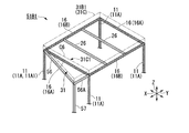
- FIG. 16 schematically shows a perspective view of an analytical model in the fireproof structure 51B of the example. Note that the second floor portion 31B is not shown in FIG.
- the refractory structure 51B corresponds to the above-mentioned second refractory structure 51B.
- the fireproof coated beams 16A, 16B, and 16C were formed of SS400, which is a general structural rolled steel, and were H-section steels having a cross-sectional shape of 350 ⁇ 175 ⁇ 7 ⁇ 11 mm.
- the reduced fireproof coated beam 26B1 arranged on the most fireproof coated beam 16C side is formed of SS400 material and is an H-shaped steel having a cross-sectional shape of 350 ⁇ 175 ⁇ 7 ⁇ 11 mm. did.
- the reduced fireproof coated beams 26B2 other than the reduced fireproof coated beams 26B1 were formed of SS400 material and were H-section steels having a cross-sectional shape of 300 ⁇ 150 ⁇ 6.5 ⁇ 9 mm. .
- the pitch of the pair of fireproof coated beams 16B in the first intersecting direction X was 9 m.
- the pitch in the second cross direction Y of the three reduced fireproof coated beams 26B was set to 3 m.
- the pitch in the second intersecting direction Y of the fireproof covered beam 16A and the reduced fireproof covered beam 26B2 adjacent to the fireproof covered beam 16A in the second intersecting direction Y was set to 3 m.
- the pitch in the second intersecting direction Y of the joint between the longer fireproof covered beam 16B and the fireproof covered beam 16C of the pair of fireproof covered beams 16B and the reduced fireproof covered beam 26B1 was 3 m.
- the joint between the fireproof covered beam 16A and the fireproof covered beam 16B is assumed to be held at the positions in the first intersecting direction X, the second intersecting direction Y, and the vertical direction Z.
- the joint portion is supposed to be rotatable about axes parallel to the first intersecting direction X, the second intersecting direction Y, and the vertical direction Z.
- the same constraint condition was also applied to the joint between the fireproof coated beam 16C and the fireproof coated beam 16B.
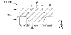
- FIG. 17 shows a vertical sectional view of an analytical model of the second floor portion 31B in the fire resistant structure 51B of the example.
- the length of the lower end of the convex portion 33a in the first intersecting direction X was 125 mm. It is assumed that the lower end of the convex portion 33a is arranged at a position closer to the center of the convex portion 33a by 25 mm in the first intersecting direction X than the upper end of the convex portion 33a. It is assumed that the concrete 33 extends by 62.5 mm on both sides in the first intersecting direction X with respect to the convex portion 33a.
- the length of the convex portion 33a in the vertical direction Z is set to 50 mm.
- the distance from the upper end of the reinforcing bar 34 to the upper surface of the concrete 33 was set to 30 mm.
- the thickness of the second floor portion 31B was 130 mm.
- the second floor 31B does not include the deck plate 32. That is, in the analysis model of the second floor portion 31B, the deck plate 32 is not set.
- the plurality of concretes 33 configured in this way are arranged in the first intersecting direction X at a pitch of 300 mm.
- the concrete 33 is arranged so that the convex portion 33a extends along the second intersecting direction Y.
- the concrete 33 was ordinary concrete (NC) and had a water content of 10%.
- the design standard strength Fc of the concrete 33 was 24 N/mm 2 (Newton-per-square millimeter).
- the reinforcing bar 34 is a deformed steel bar (SD295A) according to JIS G 3112:2010, the regulations for steel bars for reinforced concrete, and has an outer diameter of 6 mm.
- the plurality of second reinforcing bars 36 are arranged in the first intersecting direction X at a pitch of 150 mm.
- the plurality of first reinforcing bars 35 are arranged in the second intersecting direction Y at a pitch of 150 mm.
- FIG. 18 schematically shows a perspective view of an analytical model of the fire resistant structure 51A of the comparative example.
- the first floor is not shown in FIG.
- the refractory structure 51A corresponds to the above-described first refractory structure 51A including the two reduced fireproof coated beams 26A.
- the fireproof coated beams 16A and 16B of the fireproof structure 51A have the same configuration as the fireproof coated beams 16A, 16B and 16C of the fireproof structure 41B. That is, the fireproof coated beams 16A and 16B were made of SS400 material and were H-section steels having a sectional shape of 350 ⁇ 175 ⁇ 7 ⁇ 11 mm.
- the reduced fireproof coated beam 26A of the fireproof structure 51A has the same configuration as the reduced fireproof coated beam 26B2 of the fireproof structure 51B.
- the pitch of the pair of fireproof coated beams 16B in the first intersecting direction X was 9 m.
- the pitch in the second intersecting direction Y of the two reduced fireproof coated beams 26A was set to 3 m.
- the pitch in the second intersecting direction Y of the fireproof covered beam 16A and the reduced fireproof covered beam 26A adjacent to the fireproof covered beam 16A in the second intersecting direction Y was set to 3 m.
- the joint between the fireproof covered beam 16A and the fireproof covered beam 16B is assumed to be held at the positions in the first intersecting direction X, the second intersecting direction Y, and the vertical direction Z.
- the joint portion is supposed to be rotatable about axes parallel to the first intersecting direction X, the second intersecting direction Y, and the vertical direction Z.
- the shape of the vertical cross section of the first floor portion is the same as the shape of the vertical cross section of the second floor portion 31B.
- FIG. 19 schematically shows a perspective view of an analytical model of the refractory structure 51C of the comparative example. Note that FIG. 19 does not show the third floor portion supported by the fireproof coated beams 16A, 16B, 16C and the like.
- the refractory structure 51C is the same as the refractory structure 51B of the embodiment, except that the reduced refractory coated beam 26B1 is provided with a fireproof coating to form a fireproof coated beam 16G.
- the third floor has the same configuration as the second floor 31B of the fire resistant structure 51B of the embodiment.
- the floor portion whose periphery is supported by the refractory-covered beams 16A, 16B, and 16G has a rectangular shape in plan view.
- the refractory structure 51B of the example and the refractory structures 51A and 51C of the comparative example are heated based on the heating curve defined in ISO 834, the flexure of the floor with respect to the heating time, the in-plane stress of the floor Etc. were obtained by simulation.
- the temperature of the refractory structure rises by heating the refractory structure supported under the above constraint conditions.
- the refractory structure expands and stress acts in the refractory structure, and the rigidity and yield strength of the refractory structure change.
- the fireproof covered column 11, the fireproof covered beam 16, and the reinforcing bar 34 have a predetermined rigidity and proof stress, but the reduced fireproof covered beam 26 has no rigidity and proof stress.
- FIG. 20 shows the simulation result of the flexure of the floor.
- the horizontal axis represents the heating time (minutes, the elapsed time from the start of heating).
- the vertical axis represents the flexure (mm) at approximately the center of the floor of the refractory structure 51B, 51A, 51C.
- FIG. 16 shows a position P1 at the substantially center of the second floor portion 31B.
- FIG. 18 shows a substantially central position P2 of the first floor portion
- FIG. 19 shows a substantially central position P3 of the third floor portion.
- a solid line and a line L1 indicated by a circle represent the bending at the position P1 of the second floor portion 31B in the fire resistant structure 51B of the example.
- a dotted line and a line L2 indicated by a triangle represent the bending at the position P2 of the first floor portion in the refractory structure 51A of the comparative example.
- a one-dot chain line and a line L3 indicated by a square mark represent the bending at the position P3 of the third floor portion in the refractory structure 51C of the comparative example.
- the deflection of the second floor portion 31B at the position P1 is sufficiently large and the second floor portion 31B collapses
- the deflection of the second floor portion 31B at the position P1 is two points in FIG. It has been found that the deflection increases sharply with respect to the heating time to the extent indicated by the chain line L4. According to this simulation result, it was found that as the heating time increases, the flexure in the substantially central portions of the second floor portion 31B, the first floor portion, and the third floor portion gradually increases. It was found that the deflection at the position P3 of the third floor is larger than the deflection at the position P2 of the first floor for a predetermined heating time of 0 to 30 minutes. It was found that the bending of the second floor portion 31B at the position P1 was larger than the bending of the third floor portion at the position P3.
- the threshold value K(m) which is the floor bending limit value, is defined by the above equation (6).
- the threshold value K is obtained as follows, for example. That is, the floor portion 66 has two pairs of opposite sides (a pair of sides 66a and 66b and a pair of sides 66c and 66d). The length of the line connecting the midpoint of the side 66a and the midpoint of the side 66b is defined as the length L of the first span. The length of the line connecting the midpoint of the side 66c and the midpoint of the side 66d is defined as the length 1 of the second span. Using these lengths L and l, the threshold value K is calculated from the equation (6).
- the value of the threshold K is calculated by using the method of calculating the threshold K when the floor 66 has a rectangular shape other than the rectangular shape when the floor has a rectangular shape.
- the value of the threshold value K in this case matches the value of the threshold value K in the case where the floor portion shown by the equation (6) in Non-Patent Document 1 is rectangular. That is, the method of obtaining the threshold value K proposed by the inventors extends the method of obtaining the threshold value K shown by the equation (6) in Non-Patent Document 1 to the case where the floor is a quadrangular shape other than a rectangular shape. ing.
- the inventors propose a method of obtaining the value of the threshold value K as a method of obtaining the value of the threshold value K, which is obtained by expanding the equation (6) of Non-Patent Document 1.
- the length of the refractory structure 51B of the embodiment is defined, and the second floor portion 31B has a quadrangular shape other than a rectangular shape in plan view.
- a line corresponding to 654 mm is shown as a solid line L6 in FIG. That is, it is determined that the second floor portion 31B is retained without collapsing until the value of the line L1 representing the refractory structure 51B of the embodiment reaches at least the value of the line L6.
- the maximum value of the bending of the second floor portion 31B of the refractory structure 51B of the example is less than the threshold value K of 654 mm due to the so-called membrane effect. I knew it was. It was found that the maximum value of the deflection of the first floor of the refractory structure 51A and the third floor of the refractory structure 51C of the comparative example was less than the threshold value K of 600 mm. Further, the ratio of the maximum deflection of the refractory structure 51B to the threshold value K of 654 mm and the ratio of the maximum deflection of the refractory structures 51A and 51C to the threshold value K of 600 mm may be substantially the same. Do you get it. It was found that the fire resistant performance of the fire resistant structure 51B of the example was maintained at the same level as the fire resistant performance of the fire resistant structures 51B and 51C of the comparative example.
- a desired time such as 1 hour or 2 hours is used as the heating time, based on the fire resistance performance stipulated in the Building Standards Law of Japan.
- the refractory structure 51B of the example does not include the refractory covered beam 16G as compared with the refractory structure 51C of the comparative example, and the refractory covered beam 16 is not joined to the portion other than the periphery of the second floor portion 31B. For this reason, it was found that at the time of fire, restraint by the beam did not occur at the position (surrounding portion) of the reduced fire resistant coated beam 26B1. Then, it was found that the compressive stress and the tensile stress due to the compression at the position where the reduced fire resistant coating beam 26B1 is arranged are respectively reduced (relaxed).
- the compressive stress and tensile stress of the second floor portion 31B of the refractory structure 51B of the example are equal to or greater than the compressive stress and tensile stress of the first floor portion of the refractory structure 51A of the comparative example. .
- FIG. 28 shows changes in the principal stress of compression occurring in the plane with respect to the heating time at the corresponding positions of the second floor portion 31B of the refractory structure 51B of the example and the third floor portion of the refractory structure 51C of the comparative example. Shown in. The corresponding position on the second floor portion 31B of the refractory structure 51B of the embodiment is indicated by position P5 in FIG. The corresponding position on the third floor of the refractory structure 51C of the comparative example is indicated by position P6 in FIG.
- the horizontal axis represents the heating time
- the vertical axis represents the principal stress of compression (kN/m: kilonewton per meter) generated in the plane.
- a solid line and a line L11 indicated by a circle represent the principal stress of compression occurring in the plane of the refractory structure 51B of the example.
- a solid line and a line L13 by a square mark represent the principal stress of compression occurring in the plane of the refractory structure 51C of the comparative example.
- the principal stress of compression generated in the surface increases with the lapse of heating time.
- the principal stress of compression generated in the plane at the position P5 of the second floor portion 31B of the fire resistant structure 51B of the example is the position P6 of the third floor portion of the fire resistant structure 51C of the comparative example. It was found that the stress is smaller than the principal stress of compression that occurs in the plane at.
- the floor bending limit value described in Non-Patent Document 1 and the maximum floor bending value obtained by simulation become smaller.
- FIG. 29 a second embodiment of the present invention will be described with reference to FIG. 29 and FIGS. 8 and 15, but the same parts as those of the embodiment will be designated by the same reference numerals and the description thereof will be omitted. Only different points will be described.
- the second refractory structure 71B of the present embodiment has four refractory coated columns 72 in place of the four refractory coated columns 11 of the second refractory structure 51B of the first embodiment. I have it.
- FIG. 29 does not show a portion of the building other than the second refractory structure 71B.
- Each refractory-covered pillar 72 differs from the refractory-covered pillar 11 only in the length in the vertical direction Z.
- Each fireproof coated column 72 is longer than the fireproof coated column 11.
- Each refractory covered pillar 72 extends upward beyond the second floor portion 31B.
- each end of the fireproof coated beam 16 is joined to the fireproof coated column 72.
- a portion joined to the fireproof coated beam 16 (a part of the fireproof coated column) is referred to as a column piece 72a.
- the plurality of fireproof coated beams 16 and the plurality of pillar pieces 72a are formed in an annular shape as a whole.
- the periphery of the second floor portion 31B is supported from below by the plurality of fireproof coated beams 16.
- the four fireproof coated beams 16 and the four pillar pieces 72a are formed in an annular shape as a whole.
- the number of fireproof coated beams 16 and the number of pillar pieces 72a that are formed in an annular shape as a whole are not particularly limited.
- FIG. 8 is a flowchart showing the design method S30 of this embodiment.
- This design method S30 is different from the design method S of the first embodiment in that a fireproof specification determining step S31 is performed instead of the fireproof specification determining step S5.
- the fireproof specification determining step S31 the periphery of the second floor portion 31B partitioned from the floor 31 is set to be supported from below by the plurality of fireproof covered beams 16. Further, the plurality of fireproof coated beams 16 and the plurality of pillar pieces 72a are set to be formed in an annular shape as a whole.
- FIG. 15 is a flowchart which shows the construction method S40 of this embodiment.
- This construction method S40 is different from the construction method S20 of the first embodiment in that a covering construction step S41 is performed instead of the covering construction step S23.
- the covering construction step S41 the periphery of the second floor portion 31B partitioned from the floor 31 is supported from below by the plurality of fireproof covering beams 16. Further, the plurality of fireproof coated beams 16 and the plurality of pillar pieces 72a are formed in an annular shape as a whole.
- the designing method S30 of the present embodiment by performing the structure determining step S3 and the fireproof specification determining step S31, the surroundings of the second floor portion 31B have a certain rigidity and yield strength even during a fire. It is set so that it can be maintained and is supported from below by the plurality of fireproof covered beams 16 and the plurality of pillar pieces 72a which are formed in an annular shape as a whole.
- the two first center lines C6 set the second floor portion 31B to be trapezoidal in plan view. All of the corners of the second floor portion 31B are set so as to overlap the plurality of fireproof coated columns 11 in a plan view, so that all the corners are supported by the plurality of fireproof coated columns 11.
- the reinforcing bars 34 included in the second floor portion 31B are the tensile force F2 between the ends of the second floor portion 31B in the first intersecting direction X and the end portion of the second floor portion 31B in the second intersecting direction Y.
- the tensile force F3 between them is transmitted.
- the center portion of the second floor portion 31B in a plan view is bent downward so as to be convex.
- the periphery of the second floor portion 31B is supported by the fireproof coated beam 16.
- the reinforcing bar 34 extended by the bending of the second floor portion 31B transmits the tensile forces F2 and F3 in the first intersecting direction X and the second intersecting direction Y, respectively, so that the central portion of the second floor portion 31B is moved. Supported. Therefore, even if the shape of the second floor portion 31B is trapezoidal, the second refractory structure 71B can be set to maintain a constant fire resistance performance.
- the construction method S40 of the present embodiment by performing the column and beam construction step S21 and the covering construction step S41, it is possible to maintain a certain rigidity and proof stress around the second floor portion 31B even in the event of a fire. Is supported from below by a plurality of fireproof covered beams 16 and a plurality of pillar pieces 72a formed in an annular shape. At this time, the second floor portion 31B is formed in a trapezoidal shape in a plan view by the two first center lines C6. All of the corners of the second floor portion 31B overlap with the plurality of fireproof coated columns 11 in a plan view, so that all the corners are supported by the plurality of fireproof coated columns 11.
- the reinforcing bars 34 included in the second floor portion 31B are the tensile force F2 between the ends of the second floor portion 31B in the first intersecting direction X and the end portion of the second floor portion 31B in the second intersecting direction Y.
- the tensile force F3 between them is transmitted.
- the center portion of the second floor portion 31B in a plan view is bent downward so as to be convex.
- the periphery of the second floor portion 31B is supported by the fireproof coated beam 16.
- the reinforcing bar 34 extended by the bending of the second floor portion 31B transmits the tensile forces F2 and F3 in the first intersecting direction X and the second intersecting direction Y, respectively, so that the central portion of the second floor portion 31B is moved. Supported. Therefore, even if the shape of the second floor portion 31B is trapezoidal, the second refractory structure 71B can be maintained to have a constant fire resistance performance.
- the periphery of the second floor portion 31B can maintain constant rigidity and proof strength even in the event of a fire, and the plurality of fireproof covered beams 16 formed in an annular shape as a whole. And is supported from below by the plurality of pillar pieces 72a.
- the two first center lines C6 form the second floor portion 31B in a trapezoidal shape in a plan view. All of the corners of the second floor portion 31B overlap with the plurality of fireproof coated columns 11 in a plan view, so that all the corners are supported by the plurality of fireproof coated columns 11.
- the reinforcing bars 34 included in the second floor portion 31B are the tensile force F2 between the ends of the second floor portion 31B in the first intersecting direction X and the end portion of the second floor portion 31B in the second intersecting direction Y.
- the tensile force F3 between them is transmitted.
- the center portion of the second floor portion 31B in a plan view is bent downward so as to be convex.
- the periphery of the second floor portion 31B is supported by the fireproof coated beam 16.
- the reinforcing bar 34 extended by the bending of the second floor portion 31B transmits the tensile forces F2 and F3 in the first intersecting direction X and the second intersecting direction Y, respectively, so that the central portion of the second floor portion 31B is moved. Supported. Therefore, even if the shape of the second floor portion 31B is trapezoidal, the second refractory structure 71B can be maintained to have a constant fire resistance performance.
- the second refractory structures 31B and 71B of the first and second embodiments may not include the reduced fire resistant coating beam 26.
- the fireproof covered beam 16 may be joined to a portion other than the periphery of the second floor portion 31B.
- the second floor may have a triangular shape or a polygonal shape having five or more corners (corners) in a plan view.
- the determination step S7 need not be performed.
- a design method of a refractory structure, a construction method of a refractory structure, and a refractory structure of the present disclosure are refractory structures capable of maintaining a constant fire resistance performance while making a floor shape a polygonal shape different from a rectangular shape. It can be suitably used as a product, a design method thereof, and a construction method.
Landscapes
- Engineering & Computer Science (AREA)
- Architecture (AREA)
- Physics & Mathematics (AREA)
- Electromagnetism (AREA)
- Civil Engineering (AREA)
- Structural Engineering (AREA)
- Building Environments (AREA)
Abstract
耐火被覆が施された複数の耐火被覆柱と、耐火被覆が施され、複数の耐火被覆柱を互いに接合する複数の耐火被覆梁と、引張力伝達部材を含むスラブから区画された床部とを備え、平面視において、床部は矩形状とは異なる多角形状に形成された耐火構造物を設計する耐火構造物の設計方法であって、スラブ、梁、及び柱の配置を決定する構造決定工程と、スラブから区画された床部の周囲を、梁に耐火被覆を施した耐火被覆梁により下方から支持させるように設定する耐火仕様決定工程と、を行う。
Description
本発明は、耐火構造物の設計方法、耐火構造物の施工方法、及び耐火構造物に関する。
本願は、2018年11月27日に、日本に出願された特願2018-221045号に基づき優先権を主張し、その内容をここに援用する。
本願は、2018年11月27日に、日本に出願された特願2018-221045号に基づき優先権を主張し、その内容をここに援用する。
従来、鉄骨造の構造物が知られている(例えば、非特許文献1参照)。鉄骨造の構造物は、柱及び梁を互いに接合し、梁上で床(スラブ)を支持して構成される。床は、平面視で複数の隅部を有する矩形状に形成されている。柱は、床の複数の隅部のそれぞれを下方から支持している。
構造物では、火災時に床の撓みを抑える等の耐火性能を高めるために、鉄骨造の柱、梁に耐火被覆を施す場合がある。耐火被覆を施された柱は、耐火被覆柱となる。耐火被覆を施された梁は、耐火被覆梁となる。
構造物では、火災時に床の撓みを抑える等の耐火性能を高めるために、鉄骨造の柱、梁に耐火被覆を施す場合がある。耐火被覆を施された柱は、耐火被覆柱となる。耐火被覆を施された梁は、耐火被覆梁となる。
構造物で火災が発生すると、柱及び梁の温度は高くなる。しかしながら、耐火被覆柱及び耐火被覆梁は、それぞれの温度が高くなっても一定の剛性及び耐力を維持する。よって、耐火被覆柱及び耐火被覆梁は、火災時でも床を支持することができる。一方で、耐火被覆を施していない柱及び梁、耐火被覆柱及び耐火被覆梁よりも耐火被覆が削減された柱及び梁では、火災時には剛性及び耐力が無くなる(剛性及び耐力が維持できない)とみなされる。火災時には、これらの剛性及び耐力が小さくなるとみなされる場合がある。耐火被覆を施していない柱及び梁等を備える構造物では、耐火性能が低下する。
柱及び梁に耐火被覆を施すのには多大な労力を要するため、耐火被覆を省略することが望まれている。
柱及び梁に耐火被覆を施すのには多大な労力を要するため、耐火被覆を省略することが望まれている。
一般的に構造物は、柱、梁、及びスラブ等により構成される。スラブは、引張力伝達部材を含む。例えば、引張力伝達部材は鉄筋である。柱に耐火被覆を施して耐火被覆柱としたり、梁に耐火被覆を施して耐火被覆梁とすることで、構造物が耐火構造物となる。スラブは、柱及び梁により、平面視で複数の隅部を有する矩形状の床部に区画される。
図30に示すように、特許文献1に開示された耐火構造物300を設計する耐火構造物の設計方法では、耐火被覆柱部材301と減耐火被覆柱部材302との間に、梁部材303が接合されるように設定されている。なお、図30以下の図では耐火被覆が削減されることなく施された柱及び梁に、ハッチングを付して示している。
耐火被覆柱部材301は、耐火被覆が施された柱部材である。減耐火被覆柱部材302は、耐火被覆柱部材301よりも耐火被覆が削減された柱部材である。
耐火構造物300の平面視において、複数の耐火被覆柱部材301及び複数の減耐火被覆柱部材302が、幅方向E1及び奥行方向E2にそれぞれ互いに間隔を空けて並べて配置されている。複数の耐火被覆柱部材301及び複数の減耐火被覆柱部材302は、全体として格子状(grid)に配置されている。この際に、減耐火被覆柱部材302に対して幅方向E1及び奥行方向E2にそれぞれ隣り合う柱部材が耐火被覆柱部材301となるように配置されている。梁部材303は、格子状に配置された複数の耐火被覆柱部材301及び複数の減耐火被覆柱部材302同士を接合している。
耐火被覆柱部材301は、耐火被覆が施された柱部材である。減耐火被覆柱部材302は、耐火被覆柱部材301よりも耐火被覆が削減された柱部材である。
耐火構造物300の平面視において、複数の耐火被覆柱部材301及び複数の減耐火被覆柱部材302が、幅方向E1及び奥行方向E2にそれぞれ互いに間隔を空けて並べて配置されている。複数の耐火被覆柱部材301及び複数の減耐火被覆柱部材302は、全体として格子状(grid)に配置されている。この際に、減耐火被覆柱部材302に対して幅方向E1及び奥行方向E2にそれぞれ隣り合う柱部材が耐火被覆柱部材301となるように配置されている。梁部材303は、格子状に配置された複数の耐火被覆柱部材301及び複数の減耐火被覆柱部材302同士を接合している。
複数の梁部材303には、合成スラブ304が架設されている。図示はしないが、合成スラブ304は、コンクリートと、デッキプレートと、スラブ筋(引張力伝達部材)と、を有している。デッキプレートは、打込み鋲接合又はボルト接合等により梁部材303の上面に固定されている。
以上のように構成された耐火構造物300において、耐火被覆柱部材301では、外気温が常温の通常時だけでなく火災時においても剛性及び耐力が維持できる。一方で、減耐火被覆柱部材302では、通常時において剛性及び耐力が維持できるが、火災時においては剛性及び耐力が維持できない。火災時において、減耐火被覆柱部材302の剛性及び耐力が無くなるとみなされる。
以上のように構成された耐火構造物300において、耐火被覆柱部材301では、外気温が常温の通常時だけでなく火災時においても剛性及び耐力が維持できる。一方で、減耐火被覆柱部材302では、通常時において剛性及び耐力が維持できるが、火災時においては剛性及び耐力が維持できない。火災時において、減耐火被覆柱部材302の剛性及び耐力が無くなるとみなされる。
火災時における耐火構造物300は、図31及び図32に示すように変形する。なお、図31では合成スラブ304を示していない。図32では、変形後の減耐火被覆柱部材302及び合成スラブ304を二点鎖線で示している。
図31において、隣り合う耐火被覆柱部材301を結ぶ中心線M1上に配置された合成スラブ304を、以下では線上スラブ304aと言う。耐火被覆柱部材301、減耐火被覆柱部材302、梁部材303、及び合成スラブ304は、通常時だけでなく火災時においても重力の影響を受ける。
図31において、隣り合う耐火被覆柱部材301を結ぶ中心線M1上に配置された合成スラブ304を、以下では線上スラブ304aと言う。耐火被覆柱部材301、減耐火被覆柱部材302、梁部材303、及び合成スラブ304は、通常時だけでなく火災時においても重力の影響を受ける。
火災時において耐火被覆柱部材301の剛性及び耐力は維持できるため、図31及び図32に示すように火災時においても線上スラブ304aの上下方向E3の位置が保持される。これに対して、減耐火被覆柱部材302は火災時において剛性及び耐力が無くなるため、図32中に二点鎖線で示すように下方に向かって移動する(折れ曲がる)。
線上スラブ304a以外は上下方向E3の位置が保持されないため、合成スラブ304の各部分は、線上スラブ304aから離間するに従い、合成スラブ304に作用する重力により下方に向かって移動する。このため、火災時において、合成スラブ304は、線上スラブ304aを中心として上方に向かって凸となるように湾曲する。
湾曲した合成スラブ304では、コンクリートが圧縮力を受け、スラブ筋が引張り力を受けることで、合成スラブ304が曲げモーメントB1に耐える。合成スラブ304は、合成スラブ304に作用する重力に曲げモーメントB1により抵抗する。
線上スラブ304a以外は上下方向E3の位置が保持されないため、合成スラブ304の各部分は、線上スラブ304aから離間するに従い、合成スラブ304に作用する重力により下方に向かって移動する。このため、火災時において、合成スラブ304は、線上スラブ304aを中心として上方に向かって凸となるように湾曲する。
湾曲した合成スラブ304では、コンクリートが圧縮力を受け、スラブ筋が引張り力を受けることで、合成スラブ304が曲げモーメントB1に耐える。合成スラブ304は、合成スラブ304に作用する重力に曲げモーメントB1により抵抗する。
以上のように、耐火構造物300では、減耐火被覆柱部材302は耐火被覆柱部材301よりも耐火被覆が削減されている。しかし、耐火構造物300では、耐火構造物300の骨組みのロバストネス(Robustness、冗長性、余裕度)が生じる。このロバストネスにより、減耐火被覆柱部材302の耐火被覆が削減されていても、火災時において耐火被覆柱部材301により合成スラブ304が支持される。
特許文献2に開示された防爆耐火性被膜厚さ算出方法では、コンクリート構造体と、コンクリート構造体の表面に設けられた防爆耐火性被覆層と、を備える試験体を作製する。そして、試験体を加熱して温度の経時変化を測定し、試験体の深さと温度との関係を導く。その関係に基づいて、コンクリート構造体の温度が耐熱許容温度以下であるか否かを判定する。さらに、その結果に基づいて防爆耐火性被覆層の厚さを算出する。
図33に示すように、特許文献3に開示されたスラブ構造311は、建物310に用いられている。スラブ構造311は、大梁312と、鉄骨小梁313と、スラブ314と、を備えている。大梁312は、耐火性能を有し、柱315間に架け渡されている。鉄骨小梁313の全体又は一部は、耐火被覆処理されない。鉄骨小梁313は、大梁312に接合されている。スラブ314は、鉄筋コンクリート製である。スラブ314は、大梁312と鉄骨小梁313とに支持される。
ここで、複数の柱315のうち、スラブ314の周囲に位置する柱315を外柱315Aと規定する。複数の柱315のうち外柱315A以外を、内柱315Bと規定する。平面視において、内柱315Bの中心(例えば重心)と外柱315Aの中心とを通り、スラブ314の周囲に達する第1基準線C1を規定する。内柱315Bの中心同士を通る第2基準線C2を規定する。
このとき平面視において、スラブ314は、第1基準線C1及び第2基準線C2の少なくとも一方により、床部314A,314B等に区画される。床部314A,314B等は、平面視において矩形状である。床部314A,314B等は、隅部が柱315により欠けた形状になることのない、設計上の区画(設計区画)である。
平面視において、床部314A,314B等が備える隅部は全て、複数の柱315に重なるように配置される。
このとき平面視において、スラブ314は、第1基準線C1及び第2基準線C2の少なくとも一方により、床部314A,314B等に区画される。床部314A,314B等は、平面視において矩形状である。床部314A,314B等は、隅部が柱315により欠けた形状になることのない、設計上の区画(設計区画)である。
平面視において、床部314A,314B等が備える隅部は全て、複数の柱315に重なるように配置される。
以下、本明細書では、スラブから区画される床部の平面視における形状は、柱の中心を通る線、及びスラブの周囲によりスラブから区画された床部の形状のことを意味する。
特許文献4に開示された耐火構造は、複数の柱部材と、複数の大梁と、小梁と、床スラブと、を備えている。
各大梁は、柱部材に架設されている。複数の大梁は、小梁に対して略直交させて設けられる一対の直交大梁と、小梁に対して略平行に設けられる一対の平行大梁とを有している。直交大梁及び平行大梁の何れか一方の大梁(以下、第1大梁と言う)に、耐火被覆が施される。直交大梁及び平行大梁の何れか他方となる大梁並びに小梁の耐火被覆は、第1大梁に施された耐火被覆よりも削減される。小梁は、複数の大梁で取り囲んだ内側に設けられる。床スラブは、大梁及び小梁の上方に設けられる。
各大梁は、柱部材に架設されている。複数の大梁は、小梁に対して略直交させて設けられる一対の直交大梁と、小梁に対して略平行に設けられる一対の平行大梁とを有している。直交大梁及び平行大梁の何れか一方の大梁(以下、第1大梁と言う)に、耐火被覆が施される。直交大梁及び平行大梁の何れか他方となる大梁並びに小梁の耐火被覆は、第1大梁に施された耐火被覆よりも削減される。小梁は、複数の大梁で取り囲んだ内側に設けられる。床スラブは、大梁及び小梁の上方に設けられる。
Olivier Vassart, Bin Zhao "MEMBRANE ACTION OF COMPOSITE STRUCTURES IN CASE OF FIRE", 2013 No.132, ECCS, Technical Committee 3 Fire Safety.
特許文献1及び2に開示された耐火構造物の設計方法では、スラブから区画される床部の形状は、明記されていない。非特許文献1、特許文献3及び4に開示された耐火構造物の設計方法では、平面視における床部の形状はそれぞれ矩形状である。
耐火構造物の構成が多様化する中で、床部の形状が矩形状とは異なる多角形状であっても、床部が一定の耐火性能を維持できることが望まれている。なお、ここで言う床部の耐火性能とは、火災時に床部の撓みを抑えることや、床部の曲げ耐力よりも外力が大きくなることを抑えることを意味する。
耐火構造物の構成が多様化する中で、床部の形状が矩形状とは異なる多角形状であっても、床部が一定の耐火性能を維持できることが望まれている。なお、ここで言う床部の耐火性能とは、火災時に床部の撓みを抑えることや、床部の曲げ耐力よりも外力が大きくなることを抑えることを意味する。
本発明は、このような問題点に鑑みてなされたものであって、床部の形状を矩形状とは異なる多角形状にしつつ、一定の耐火性能を維持することができる耐火構造物の設計方法、耐火構造物の施工方法、及び耐火構造物を提供することを目的とする。
前記課題を解決するために、この発明は以下の手段を提案している。
(1)本発明の第一の態様は、耐火被覆が施された複数の耐火被覆柱と、耐火被覆が施され、前記複数の耐火被覆柱を互いに接合する複数の耐火被覆梁と、引張力伝達部材を含むスラブから区画された床部と、を備え、平面視において、前記複数の耐火被覆柱のうち前記スラブの周囲に位置する前記耐火被覆柱を耐火被覆された外柱と規定し、前記複数の耐火被覆柱のうち前記耐火被覆された外柱以外を耐火被覆された内柱と規定したときに、平面視において、前記床部は、前記耐火被覆された内柱の中心と前記耐火被覆された外柱の中心とを通り前記スラブの周囲に達する第1中心線、及び前記耐火被覆された内柱の中心同士を通る第2中心線の少なくとも一方により区画された前記スラブの一部分であり、平面視において、前記床部は矩形状とは異なる多角形状に形成され、平面視において、前記床部が備える隅部は全て、前記複数の耐火被覆柱に重なるように配置され、前記複数の耐火被覆梁は、全体として環状に形成され、前記床部の周囲は、前記複数の耐火被覆梁により下方から支持され、前記床部の平面内で互いに交差する方向を第1交差方向、第2交差方向と規定したときに、前記引張力伝達部材は、前記床部の前記第1交差方向の端部間の引張力、及び、前記床部の前記第2交差方向の端部間の引張力をそれぞれ伝達する耐火構造物を設計する耐火構造物の設計方法であって、構造計算を行うことにより、前記スラブ、前記スラブを下方から支持する複数の梁、及び前記複数の梁を支持する柱の配置を決定する構造決定工程と、前記スラブから区画された前記床部の周囲を、前記梁に耐火被覆を施した前記耐火被覆梁により下方から支持させるように設定する耐火仕様決定工程と、を行う耐火構造物の設計方法である。
(1)本発明の第一の態様は、耐火被覆が施された複数の耐火被覆柱と、耐火被覆が施され、前記複数の耐火被覆柱を互いに接合する複数の耐火被覆梁と、引張力伝達部材を含むスラブから区画された床部と、を備え、平面視において、前記複数の耐火被覆柱のうち前記スラブの周囲に位置する前記耐火被覆柱を耐火被覆された外柱と規定し、前記複数の耐火被覆柱のうち前記耐火被覆された外柱以外を耐火被覆された内柱と規定したときに、平面視において、前記床部は、前記耐火被覆された内柱の中心と前記耐火被覆された外柱の中心とを通り前記スラブの周囲に達する第1中心線、及び前記耐火被覆された内柱の中心同士を通る第2中心線の少なくとも一方により区画された前記スラブの一部分であり、平面視において、前記床部は矩形状とは異なる多角形状に形成され、平面視において、前記床部が備える隅部は全て、前記複数の耐火被覆柱に重なるように配置され、前記複数の耐火被覆梁は、全体として環状に形成され、前記床部の周囲は、前記複数の耐火被覆梁により下方から支持され、前記床部の平面内で互いに交差する方向を第1交差方向、第2交差方向と規定したときに、前記引張力伝達部材は、前記床部の前記第1交差方向の端部間の引張力、及び、前記床部の前記第2交差方向の端部間の引張力をそれぞれ伝達する耐火構造物を設計する耐火構造物の設計方法であって、構造計算を行うことにより、前記スラブ、前記スラブを下方から支持する複数の梁、及び前記複数の梁を支持する柱の配置を決定する構造決定工程と、前記スラブから区画された前記床部の周囲を、前記梁に耐火被覆を施した前記耐火被覆梁により下方から支持させるように設定する耐火仕様決定工程と、を行う耐火構造物の設計方法である。
(2)前記(1)に記載の耐火構造物の設計方法では、前記耐火仕様決定工程において、平面視で所定の形状に区画された第1床片を前記床部とし、前記床部の圧縮の主応力が、予め定められた応力閾値を超えるか否かを判定する判定工程を行い、前記判定工程において、前記圧縮の主応力の最大値が、前記床部の周囲の一部である周囲部分で生じて、前記圧縮の主応力の最大値が予め定められた応力閾値を超えると判定されたときには、前記床部が前記第1床片、及び、前記第1床片の前記周囲部分に連なる第2床片からなる形状に区画されると仮定し、前記床部が平面視で矩形状とは異なる多角形状であると仮定して、少なくとも前記耐火仕様決定工程を行い、さらに前記判定工程を行ってもよい。
(3)前記(1)に記載の耐火構造物の設計方法では、前記耐火仕様決定工程において、前記床部は平面視で矩形状とは異なる多角形状であると仮定し、前記床部の圧縮の主応力が、予め定められた応力閾値を超えるか否かを判定する判定工程を行ってもよい。
(3)前記(1)に記載の耐火構造物の設計方法では、前記耐火仕様決定工程において、前記床部は平面視で矩形状とは異なる多角形状であると仮定し、前記床部の圧縮の主応力が、予め定められた応力閾値を超えるか否かを判定する判定工程を行ってもよい。
(4)本発明の第二の態様は、耐火被覆が施された複数の耐火被覆柱と、耐火被覆が施され、前記複数の耐火被覆柱を互いに接合する複数の耐火被覆梁と、引張力伝達部材を含むスラブから区画された床部と、を備え、平面視において、前記複数の耐火被覆柱のうち前記スラブの周囲に位置する前記耐火被覆柱を耐火被覆された外柱と規定し、前記複数の耐火被覆柱のうち前記耐火被覆された外柱以外を耐火被覆された内柱と規定したときに、平面視において、前記床部は、前記耐火被覆された内柱の中心と前記耐火被覆された外柱の中心とを通り前記スラブの周囲に達する第1中心線、及び前記耐火被覆された内柱の中心同士を通る第2中心線の少なくとも一方により区画された前記スラブの一部分であり、平面視において、前記床部は矩形状とは異なる多角形状に形成され、平面視において、前記床部が備える隅部は全て、前記複数の耐火被覆柱に重なるように配置され、前記複数の耐火被覆梁及び前記複数の耐火被覆柱の一部は、全体として環状に形成され、前記床部の周囲は、前記複数の耐火被覆梁により下方から支持され、前記床部の平面内で互いに交差する方向を第1交差方向、第2交差方向と規定したときに、前記引張力伝達部材は、前記床部の前記第1交差方向の端部間の引張力、及び、前記床部の前記第2交差方向の端部間の引張力をそれぞれ伝達する耐火構造物を設計する耐火構造物の設計方法であって、構造計算を行うことにより、前記スラブ、前記スラブを下方から支持する複数の梁、及び前記複数の梁を支持する複数の柱の配置を決定する構造決定工程と、前記スラブから区画された前記床部の周囲を、前記梁に耐火被覆を施した前記耐火被覆梁により下方から支持させるとともに、前記複数の柱に耐火被覆を施した前記複数の耐火被覆柱の一部及び前記複数の耐火被覆梁が全体として環状に形成されるように設定する耐火仕様決定工程と、を行う耐火構造物の設計方法である。
(5)本発明の第三の態様は、前記(1)から(4)のいずれかに記載の耐火構造物の設計方法により設計された耐火構造物である。
(6)本発明の第四の態様は、耐火被覆が施された複数の耐火被覆柱と、耐火被覆が施され、前記複数の耐火被覆柱を互いに接合する複数の耐火被覆梁と、引張力伝達部材を含むスラブから区画された床部と、を備え、平面視において、前記複数の耐火被覆柱のうち前記スラブの周囲に位置する前記耐火被覆柱を耐火被覆された外柱と規定し、前記複数の耐火被覆柱のうち前記耐火被覆された外柱以外を耐火被覆された内柱と規定したときに、平面視において、前記床部は、前記耐火被覆された内柱の中心と前記耐火被覆された外柱の中心とを通り前記スラブの周囲に達する第1中心線、及び前記耐火被覆された内柱の中心同士を通る第2中心線の少なくとも一方により区画された前記スラブの一部分であり、平面視において、前記床部は矩形状とは異なる多角形状に形成され、平面視において、前記床部が備える隅部は全て、前記複数の耐火被覆柱に重なるように配置され、前記複数の耐火被覆梁は、全体として環状に形成され、前記床部の周囲は、前記複数の耐火被覆梁により下方から支持され、前記床部の平面内で互いに交差する方向を第1交差方向、第2交差方向と規定したときに、前記引張力伝達部材は、前記床部の前記第1交差方向の端部間の引張力、及び、前記床部の前記第2交差方向の端部間の引張力をそれぞれ伝達する耐火構造物を施工する耐火構造物の施工方法であって、前記スラブ、前記スラブを下方から支持する複数の梁、及び前記複数の梁を支持する柱を施工する柱梁施工工程と、前記複数の梁の少なくとも一部に耐火被覆を施して前記複数の耐火被覆梁とすることで、前記床部の周囲を、前記複数の耐火被覆梁により下方から支持させる被覆施工工程と、を行う耐火構造物の施工方法である。
(7)本発明の第五の態様は、耐火被覆が施された複数の耐火被覆柱と、耐火被覆が施され、前記複数の耐火被覆柱を互いに接合する複数の耐火被覆梁と、引張力伝達部材を含むスラブから区画された床部と、を備え、平面視において、前記複数の耐火被覆柱のうち前記スラブの周囲に位置する前記耐火被覆柱を耐火被覆された外柱と規定し、前記複数の耐火被覆柱のうち前記耐火被覆された外柱以外を耐火被覆された内柱と規定したときに、平面視において、前記床部は、前記耐火被覆された内柱の中心と前記耐火被覆された外柱の中心とを通り前記スラブの周囲に達する第1中心線、及び前記耐火被覆された内柱の中心同士を通る第2中心線の少なくとも一方により区画された前記スラブの一部分であり、平面視において、前記床部は矩形状とは異なる多角形状に形成され、平面視において、前記床部が備える隅部は全て、前記複数の耐火被覆柱に重なるように配置され、前記複数の耐火被覆梁及び前記複数の耐火被覆柱の一部は、全体として環状に形成され、前記床部の周囲は、前記複数の耐火被覆梁により下方から支持され、前記床部の平面内で互いに交差する方向を第1交差方向、第2交差方向と規定したときに、前記引張力伝達部材は、前記床部の前記第1交差方向の端部間の引張力、及び、前記床部の前記第2交差方向の端部間の引張力をそれぞれ伝達する耐火構造物を施工する耐火構造物の施工方法であって、前記スラブ、前記スラブを下方から支持する複数の梁、及び前記複数の梁を支持する複数の柱を施工する柱梁施工工程と、前記スラブから区画された前記床部の周囲を、前記梁に耐火被覆を施した前記耐火被覆梁により下方から支持させるとともに、前記複数の柱に耐火被覆を施した前記複数の耐火被覆柱の一部及び前記複数の耐火被覆梁を全体として環状に形成する被覆施工工程と、を行う耐火構造物の施工方法である。
(8)本発明の第六の態様は、耐火被覆が施された複数の耐火被覆柱と、耐火被覆が施され、前記複数の耐火被覆柱を互いに接合する複数の耐火被覆梁と、引張力伝達部材を含むスラブから区画された床部と、を備え、平面視において、前記複数の耐火被覆柱のうち前記スラブの周囲に位置する前記耐火被覆柱を耐火被覆された外柱と規定し、前記複数の耐火被覆柱のうち前記耐火被覆された外柱以外を耐火被覆された内柱と規定したときに、平面視において、前記床部は、前記耐火被覆された内柱の中心と前記耐火被覆された外柱の中心とを通り前記スラブの周囲に達する第1中心線、及び前記耐火被覆された内柱の中心同士を通る第2中心線の少なくとも一方により区画された前記スラブの一部分であり、平面視において、前記床部は矩形状とは異なる多角形状に形成され、平面視において、前記床部が備える隅部は全て、前記複数の耐火被覆柱に重なるように配置され、前記複数の耐火被覆梁は、全体として環状に形成され、前記床部の周囲は、前記複数の耐火被覆梁により下方から支持され、前記床部の平面内で互いに交差する方向を第1交差方向、第2交差方向と規定したときに、前記引張力伝達部材は、前記床部の前記第1交差方向の端部間の引張力、及び、前記床部の前記第2交差方向の端部間の引張力をそれぞれ伝達する耐火構造物である。
(9)前記(8)に記載の耐火構造物では、前記耐火被覆梁よりも前記耐火被覆が削減され、環状の前記複数の耐火被覆梁により囲まれた領域内に配置されて、端部が前記複数の耐火被覆梁に接合されて前記床部を下方から支持する減耐火被覆梁を備えてもよい。
(10)前記(8)又は(9)に記載の耐火構造物では、前記床部における周囲以外の部分には、前記耐火被覆梁は接合されなくてもよい。
(11)前記(8)から(10)のいずれかに記載の耐火構造物では、ISO 834-11:2014に規定された加熱曲線に基づいて加熱されたときに、所望の加熱時間における前記床部の撓みの最大値が、(1)式で定められた閾値K(m)未満であってもよい。
K=(L+l)/30 ・・(1)
ただし、Lは前記床部の前記平面に沿う第1スパンの長さ(m)であり、lは前記床部の前記平面に沿うとともに前記第1スパンに交差する第2スパンの長さ(m)である。
(10)前記(8)又は(9)に記載の耐火構造物では、前記床部における周囲以外の部分には、前記耐火被覆梁は接合されなくてもよい。
(11)前記(8)から(10)のいずれかに記載の耐火構造物では、ISO 834-11:2014に規定された加熱曲線に基づいて加熱されたときに、所望の加熱時間における前記床部の撓みの最大値が、(1)式で定められた閾値K(m)未満であってもよい。
K=(L+l)/30 ・・(1)
ただし、Lは前記床部の前記平面に沿う第1スパンの長さ(m)であり、lは前記床部の前記平面に沿うとともに前記第1スパンに交差する第2スパンの長さ(m)である。
(12)本発明の第七の態様は、耐火被覆が施された複数の耐火被覆柱と、耐火被覆が施され、前記複数の耐火被覆柱を互いに接合する複数の耐火被覆梁と、引張力伝達部材を含むスラブから区画された床部と、を備え、平面視において、前記複数の耐火被覆柱のうち前記スラブの周囲に位置する前記耐火被覆柱を耐火被覆された外柱と規定し、前記複数の耐火被覆柱のうち前記耐火被覆された外柱以外を耐火被覆された内柱と規定したときに、平面視において、前記床部は、前記耐火被覆された内柱の中心と前記耐火被覆された外柱の中心とを通り前記スラブの周囲に達する第1中心線、及び前記耐火被覆された内柱の中心同士を通る第2中心線の少なくとも一方により区画された前記スラブの一部分であり、平面視において、前記床部は矩形状とは異なる多角形状に形成され、平面視において、前記床部が備える隅部は全て、前記複数の耐火被覆柱に重なるように配置され、前記複数の耐火被覆梁及び前記複数の耐火被覆柱の一部は、全体として環状に形成され、前記床部の周囲は、前記複数の耐火被覆梁により下方から支持され、前記床部の平面内で互いに交差する方向を第1交差方向、第2交差方向と規定したときに、前記引張力伝達部材は、前記床部の前記第1交差方向の端部間の引張力、及び、前記床部の前記第2交差方向の端部間の引張力をそれぞれ伝達する耐火構造物である。
前記(1)に記載の構成によれば、構造決定工程及び耐火仕様決定工程を行うことで、床部の周囲は、火災時でも一定の剛性及び耐力を維持できる環状に形成された複数の耐火被覆梁により下方から支持させるように設定される。この際に、第1中心線及び第2中心線の少なくとも一方により、床部は平面視において矩形状とは異なる多角形状に形成されるように設定される。平面視において床部の隅部は全て複数の耐火被覆柱に重なるように設定されることで、全ての隅部は複数の耐火被覆柱により支持される。床部に含まれている引張力伝達部材は、床部の第1交差方向の端部間の引張力、及び、床部の第2交差方向の端部間の引張力をそれぞれ伝達する。
火災時には、床部に作用する重力等により、床部の平面視における中央部が下方に向かって凸となるように撓む。しかし、いわゆるメンブレン効果により、床部の周囲が耐火被覆梁により支持される。そして、床部が撓むことにより伸びた引張力伝達部材が第1交差方向及び第2交差方向にそれぞれ引張力を伝達することにより、床部の中央部が支持される。従って、床部の形状が矩形状とは異なる形状であっても、耐火構造物を一定の耐火性能に維持するように設定することができる。
火災時には、床部に作用する重力等により、床部の平面視における中央部が下方に向かって凸となるように撓む。しかし、いわゆるメンブレン効果により、床部の周囲が耐火被覆梁により支持される。そして、床部が撓むことにより伸びた引張力伝達部材が第1交差方向及び第2交差方向にそれぞれ引張力を伝達することにより、床部の中央部が支持される。従って、床部の形状が矩形状とは異なる形状であっても、耐火構造物を一定の耐火性能に維持するように設定することができる。
前記(6)に記載の構成によれば、柱梁施工工程及び被覆施工工程を行うことで、床部の周囲を、火災時でも一定の剛性及び耐力を維持できる環状に形成された複数の耐火被覆梁により下方から支持させる。この際に、第1中心線及び第2中心線の少なくとも一方により、床部は平面視において矩形状とは異なる多角形状に形成される。平面視において床部の隅部は全て複数の耐火被覆柱に重なることで、全ての隅部は複数の耐火被覆柱により支持される。床部に含まれている引張力伝達部材は、床部の第1交差方向の端部間の引張力、及び、床部の第2交差方向の端部間の引張力をそれぞれ伝達する。
火災時には、床部に作用する重力等により、床部の平面視における中央部が下方に向かって凸となるように撓む。しかし、メンブレン効果により、床部の周囲が耐火被覆梁により支持される。そして、床部が撓むことにより伸びた引張力伝達部材が第1交差方向及び第2交差方向にそれぞれ引張力を伝達することにより、床部の中央部が支持される。従って、床部の形状が矩形状とは異なる形状であっても、耐火構造物を一定の耐火性能に維持することができる。
火災時には、床部に作用する重力等により、床部の平面視における中央部が下方に向かって凸となるように撓む。しかし、メンブレン効果により、床部の周囲が耐火被覆梁により支持される。そして、床部が撓むことにより伸びた引張力伝達部材が第1交差方向及び第2交差方向にそれぞれ引張力を伝達することにより、床部の中央部が支持される。従って、床部の形状が矩形状とは異なる形状であっても、耐火構造物を一定の耐火性能に維持することができる。
前記(8)に記載の構成によれば、床部の周囲は、火災時でも一定の剛性及び耐力を維持できる環状に形成された複数の耐火被覆梁により下方から支持される。第1中心線及び第2中心線の少なくとも一方により、床部は平面視において矩形状とは異なる多角形状に形成される。平面視において床部の隅部は全て複数の耐火被覆柱に重なることで、全ての隅部は複数の耐火被覆柱により支持される。床部に含まれている引張力伝達部材は、床部の第1交差方向の端部間の引張力、及び、床部の第2交差方向の端部間の引張力をそれぞれ伝達する。
火災時には、床部に作用する重力等により、床部の平面視における中央部が下方に向かって凸となるように撓む。しかし、メンブレン効果により、床部の周囲が耐火被覆梁により支持される。そして、床部が撓むことにより伸びた引張力伝達部材が第1交差方向及び第2交差方向にそれぞれ引張力を伝達することにより、床部の中央部が支持される。従って、床部の形状が矩形状とは異なる形状であっても、耐火構造物を一定の耐火性能に維持することができる。
火災時には、床部に作用する重力等により、床部の平面視における中央部が下方に向かって凸となるように撓む。しかし、メンブレン効果により、床部の周囲が耐火被覆梁により支持される。そして、床部が撓むことにより伸びた引張力伝達部材が第1交差方向及び第2交差方向にそれぞれ引張力を伝達することにより、床部の中央部が支持される。従って、床部の形状が矩形状とは異なる形状であっても、耐火構造物を一定の耐火性能に維持することができる。
前記(4)に記載の構成によれば、構造決定工程及び耐火仕様決定工程を行うことで、床部の周囲は、火災時でも一定の剛性及び耐力を維持でき、全体として環状に形成された複数の耐火被覆梁及び複数の耐火被覆柱の一部により下方から支持させるように設定される。この際に、第1中心線及び第2中心線の少なくとも一方により、床部は平面視において矩形状とは異なる多角形状に形成されるように設定される。平面視において床部の隅部は全て複数の耐火被覆柱に重なるように設定されることで、全ての隅部は複数の耐火被覆柱により支持される。床部に含まれている引張力伝達部材は、床部の第1交差方向の端部間の引張力、及び、床部の第2交差方向の端部間の引張力をそれぞれ伝達する。
火災時には、床部に作用する重力等により、床部の平面視における中央部が下方に向かって凸となるように撓む。しかし、いわゆるメンブレン効果により、床部の周囲が耐火被覆梁により支持される。そして、床部が撓むことにより伸びた引張力伝達部材が第1交差方向及び第2交差方向にそれぞれ引張力を伝達することにより、床部の中央部が支持される。従って、床部の形状が矩形状とは異なる形状であっても、耐火構造物を一定の耐火性能に維持するように設定することができる。
火災時には、床部に作用する重力等により、床部の平面視における中央部が下方に向かって凸となるように撓む。しかし、いわゆるメンブレン効果により、床部の周囲が耐火被覆梁により支持される。そして、床部が撓むことにより伸びた引張力伝達部材が第1交差方向及び第2交差方向にそれぞれ引張力を伝達することにより、床部の中央部が支持される。従って、床部の形状が矩形状とは異なる形状であっても、耐火構造物を一定の耐火性能に維持するように設定することができる。
前記(7)に記載の構成によれば、柱梁施工工程及び被覆施工工程を行うことで、床部の周囲を、火災時でも一定の剛性及び耐力を維持でき、全体として環状に形成された複数の耐火被覆梁及び複数の耐火被覆柱の一部により下方から支持させる。この際に、第1中心線及び第2中心線の少なくとも一方により、床部は平面視において矩形状とは異なる多角形状に形成される。平面視において床部の隅部は全て複数の耐火被覆柱に重なることで、全ての隅部は複数の耐火被覆柱により支持される。床部に含まれている引張力伝達部材は、床部の第1交差方向の端部間の引張力、及び、床部の第2交差方向の端部間の引張力をそれぞれ伝達する。
火災時には、床部に作用する重力等により、床部の平面視における中央部が下方に向かって凸となるように撓む。しかし、メンブレン効果により、床部の周囲が耐火被覆梁により支持される。そして、床部が撓むことにより伸びた引張力伝達部材が第1交差方向及び第2交差方向にそれぞれ引張力を伝達することにより、床部の中央部が支持される。従って、床部の形状が矩形状とは異なる形状であっても、耐火構造物を一定の耐火性能に維持することができる。
火災時には、床部に作用する重力等により、床部の平面視における中央部が下方に向かって凸となるように撓む。しかし、メンブレン効果により、床部の周囲が耐火被覆梁により支持される。そして、床部が撓むことにより伸びた引張力伝達部材が第1交差方向及び第2交差方向にそれぞれ引張力を伝達することにより、床部の中央部が支持される。従って、床部の形状が矩形状とは異なる形状であっても、耐火構造物を一定の耐火性能に維持することができる。
前記(12)に記載の構成によれば、床部の周囲は、火災時でも一定の剛性及び耐力を維持でき、全体として環状に形成された複数の耐火被覆梁及び複数の耐火被覆柱の一部により下方から支持される。第1中心線及び第2中心線の少なくとも一方により、床部は平面視において矩形状とは異なる多角形状に形成される。平面視において床部の隅部は全て複数の耐火被覆柱に重なることで、全ての隅部は複数の耐火被覆柱により支持される。床部に含まれている引張力伝達部材は、床部の第1交差方向の端部間の引張力、及び、床部の第2交差方向の端部間の引張力をそれぞれ伝達する。
火災時には、床部に作用する重力等により、床部の平面視における中央部が下方に向かって凸となるように撓む。しかし、メンブレン効果により、床部の周囲が耐火被覆梁により支持される。そして、床部が撓むことにより伸びた引張力伝達部材が第1交差方向及び第2交差方向にそれぞれ引張力を伝達することにより、床部の中央部が支持される。従って、床部の形状が矩形状とは異なる形状であっても、耐火構造物を一定の耐火性能に維持することができる。
火災時には、床部に作用する重力等により、床部の平面視における中央部が下方に向かって凸となるように撓む。しかし、メンブレン効果により、床部の周囲が耐火被覆梁により支持される。そして、床部が撓むことにより伸びた引張力伝達部材が第1交差方向及び第2交差方向にそれぞれ引張力を伝達することにより、床部の中央部が支持される。従って、床部の形状が矩形状とは異なる形状であっても、耐火構造物を一定の耐火性能に維持することができる。
前記(2)に記載の構成によれば、一般的に、床部が、第1床片に加えて、周囲部分に連なる第2床片を備えると、周囲部分で生じた圧縮の主応力の最大値が緩和されやすくなる。床部が第1床片及び第2床片を備えるとして判定工程を行うことで、判定工程において床部の撓みの最大値が応力閾値以下であると判定されやすくすることができる。
前記(3)に記載の構成によれば、例えば判定工程において、床部の圧縮の主応力が応力閾値を超えない場合がある。このような場合に、床部の圧縮の主応力が応力閾値を超えない耐火構造物の構成を、短時間で設定することができる。
前記(3)に記載の構成によれば、例えば判定工程において、床部の圧縮の主応力が応力閾値を超えない場合がある。このような場合に、床部の圧縮の主応力が応力閾値を超えない耐火構造物の構成を、短時間で設定することができる。
前記(5)に記載の構成によれば、本発明の耐火構造物の設計方法により耐火構造物を設計することができる。本発明の耐火構造物の設計方法は、床部の形状を矩形状とは異なる多角形状にしつつ、一定の耐火性能を維持することができる方法である。
前記(9)に記載の構成によれば、火災が発生していない通常時において、床部が撓むのを抑えることができる。
前記(10)に記載の構成によれば、床部における周囲以外の部分に接合された耐火被覆梁により火災時に床部が拘束されるのが抑えられる。これにより、床部に生じる圧縮による面内応力を小さくすることができる。
前記(11)に記載の構成によれば、床部のメンブレン効果が効果的に発揮される。従って、床部が下方に向かって撓み難くすることができる。
前記(10)に記載の構成によれば、床部における周囲以外の部分に接合された耐火被覆梁により火災時に床部が拘束されるのが抑えられる。これにより、床部に生じる圧縮による面内応力を小さくすることができる。
前記(11)に記載の構成によれば、床部のメンブレン効果が効果的に発揮される。従って、床部が下方に向かって撓み難くすることができる。
本発明の耐火構造物の設計方法、耐火構造物の施工方法、及び耐火構造物によれば、床部の形状を矩形状とは異なる多角形状にしつつ、一定の耐火性能を維持することができる。
(第1実施形態)
以下、本発明に係る耐火構造物の第1実施形態が用いられる建築物を、図1から図28を参照しながら説明する。
図1及び図2に示すように、この建築物1は、複数の耐火被覆柱11と、複数の耐火被覆梁16と、複数の減耐火被覆梁26と、床(スラブ)31と、を備えている。なお、図1以下では、耐火被覆柱11及び耐火被覆梁16に、ハッチングを付して示している。
以下、本発明に係る耐火構造物の第1実施形態が用いられる建築物を、図1から図28を参照しながら説明する。
図1及び図2に示すように、この建築物1は、複数の耐火被覆柱11と、複数の耐火被覆梁16と、複数の減耐火被覆梁26と、床(スラブ)31と、を備えている。なお、図1以下では、耐火被覆柱11及び耐火被覆梁16に、ハッチングを付して示している。
耐火被覆柱11には、耐火被覆が施された鋼柱(H形鋼、十字鉄骨、角形鋼管、円形鋼管等)が用いられている。なお、耐火被覆柱11に、RC(Reinforced Concrete)、SRC(Steel Reinforced Concrete construction)、CFT(Concrete Filled steel Tube)が用いられてもよい。この場合の耐火被覆については、耐火被覆梁16で併せて説明する。
図1に示すように、各耐火被覆柱11は、上下方向Zに沿って延びている。複数の耐火被覆柱11は、上下方向Zに直交し互いに直交(交差)する第1交差方向X及び第2交差方向Yにそれぞれ互いに間隔を開けて並べて配置されている。
ここで、平面視において、複数の耐火被覆柱11のうち、床31の周囲に位置する耐火被覆柱11を耐火被覆された外柱11Aとも言う(規定する)。複数の耐火被覆柱11のうち、耐火被覆された外柱11A以外を耐火被覆された内柱11Bとも言う。耐火被覆された内柱11Bは、平面視において床31の中央部に位置する耐火被覆柱11である。
図1に示すように、各耐火被覆柱11は、上下方向Zに沿って延びている。複数の耐火被覆柱11は、上下方向Zに直交し互いに直交(交差)する第1交差方向X及び第2交差方向Yにそれぞれ互いに間隔を開けて並べて配置されている。
ここで、平面視において、複数の耐火被覆柱11のうち、床31の周囲に位置する耐火被覆柱11を耐火被覆された外柱11Aとも言う(規定する)。複数の耐火被覆柱11のうち、耐火被覆された外柱11A以外を耐火被覆された内柱11Bとも言う。耐火被覆された内柱11Bは、平面視において床31の中央部に位置する耐火被覆柱11である。
複数の耐火被覆された外柱11Aの一部(以下、耐火被覆された外柱11A1とも言う)は、第1交差方向Xに並べた位置から第2交差方向Yに位置をずらして配置されている。
図2に示すように、耐火被覆梁16は、耐火被覆17が施されたH形鋼18である。耐火被覆17には、ロックウール、グラスウール等の断熱材が用いられる。耐火被覆17は、H形鋼18の外面に、吹き付け・塗装工法・成型板工法・巻き付け工法等の各種工法により形成されている。
図1及び図2に示すように、耐火被覆梁16は、直線状に形成され、水平面に沿うように配置されている。耐火被覆梁16の両端部は、他の耐火被覆梁16及び耐火被覆柱11にそれぞれ接合されている。耐火被覆梁16は、複数の耐火被覆柱11を互いに接合している。
図1に示すように、複数の耐火被覆梁16のうちの一部である耐火被覆梁16Aは、第1交差方向Xに沿って延びている。複数の耐火被覆梁16のうちの他の一部である耐火被覆梁16Bは、第2交差方向Yに沿って延びている。複数の耐火被覆梁16のうちの残部である耐火被覆梁16Cは、端部が耐火被覆梁16A,16Bにそれぞれ接合され、第1交差方向X及び第2交差方向Yに対してそれぞれ傾斜している。
図1及び図2に示すように、耐火被覆梁16は、直線状に形成され、水平面に沿うように配置されている。耐火被覆梁16の両端部は、他の耐火被覆梁16及び耐火被覆柱11にそれぞれ接合されている。耐火被覆梁16は、複数の耐火被覆柱11を互いに接合している。
図1に示すように、複数の耐火被覆梁16のうちの一部である耐火被覆梁16Aは、第1交差方向Xに沿って延びている。複数の耐火被覆梁16のうちの他の一部である耐火被覆梁16Bは、第2交差方向Yに沿って延びている。複数の耐火被覆梁16のうちの残部である耐火被覆梁16Cは、端部が耐火被覆梁16A,16Bにそれぞれ接合され、第1交差方向X及び第2交差方向Yに対してそれぞれ傾斜している。
例えば、耐火被覆梁16C、耐火被覆梁16A、及び2本の耐火被覆梁16Bという複数の耐火被覆梁16により、耐火被覆梁集合体16Dが構成される。耐火被覆梁集合体16Dは、全体として、平面視で台形の枠である環状(ring、角環状)に形成されている。
複数の耐火被覆梁16は、複数の耐火被覆柱11により下方から支持されている。
なお、耐火被覆梁16に、RC、SRCが用いられてもよい。
複数の耐火被覆梁16は、複数の耐火被覆柱11により下方から支持されている。
なお、耐火被覆梁16に、RC、SRCが用いられてもよい。
減耐火被覆梁26は、耐火被覆梁16よりも耐火被覆が削減された梁である。減耐火被覆梁26は、耐火被覆が施されないH形鋼でもよい。減耐火被覆梁26は、耐火被覆梁16よりも耐火被覆が削減されてはいるが、幾分かの耐火被覆が施されたH形鋼でもよい。
例えば、耐火被覆梁16におけるロックウール等の耐火被覆の厚さを、「吹付けロックウール被覆耐火構造 施工品質管理指針(ロックウール工業会 吹付け部会)」に準拠して設定する。耐火被覆梁16に1時間耐火が要求される場合には、耐火被覆の厚さを25mmとする。同様に、耐火被覆梁16に2時間耐火が要求される場合には耐火被覆の厚さを45mm、3時間耐火が要求される場合には65mmとする。この場合に、減耐火被覆梁26における耐火被覆の厚さを、それぞれの耐火性能に応じた耐火被覆梁16における耐火被覆の厚さの1/10~1/2程度とする。
減耐火被覆梁26は、耐火被覆梁集合体16Dにより囲まれた領域R1内等に配置されている。
減耐火被覆梁26の両端は、複数の耐火被覆梁16に接合されている。
例えば、耐火被覆梁16におけるロックウール等の耐火被覆の厚さを、「吹付けロックウール被覆耐火構造 施工品質管理指針(ロックウール工業会 吹付け部会)」に準拠して設定する。耐火被覆梁16に1時間耐火が要求される場合には、耐火被覆の厚さを25mmとする。同様に、耐火被覆梁16に2時間耐火が要求される場合には耐火被覆の厚さを45mm、3時間耐火が要求される場合には65mmとする。この場合に、減耐火被覆梁26における耐火被覆の厚さを、それぞれの耐火性能に応じた耐火被覆梁16における耐火被覆の厚さの1/10~1/2程度とする。
減耐火被覆梁26は、耐火被覆梁集合体16Dにより囲まれた領域R1内等に配置されている。
減耐火被覆梁26の両端は、複数の耐火被覆梁16に接合されている。
図1及び図2に示すように、床31はいわゆる合成スラブであり、複数の耐火被覆梁16及び複数の減耐火被覆梁26により下方から支持されている。図2に示すように、床31は、デッキプレート(引張力伝達部材)32と、コンクリート33と、鉄筋(引張力伝達部材)34と、を備えている。なお、床31は、デッキプレート32及びコンクリート33を備えなくてもよい。床31は、鉄筋34及びコンクリート33を備えなくてもよい。床31が備える引張力伝達部材は、デッキプレート32、鉄筋34に限定されない。
例えば、デッキプレート32は、鋼板を曲げ加工して形成されている。デッキプレート32は、複数の耐火被覆梁16及び複数の減耐火被覆梁26上に配置されている。
コンクリート33は、上下方向Zが厚さ方向となる板状に形成されている。コンクリート33には、デッキプレート32の形状に対応して下方に向かって突出した凸部33aが形成されている。例えば、凸部33aは、下方に向かうに従い漸次、第1交差方向Xの幅が狭くなる。
例えば、デッキプレート32は、鋼板を曲げ加工して形成されている。デッキプレート32は、複数の耐火被覆梁16及び複数の減耐火被覆梁26上に配置されている。
コンクリート33は、上下方向Zが厚さ方向となる板状に形成されている。コンクリート33には、デッキプレート32の形状に対応して下方に向かって突出した凸部33aが形成されている。例えば、凸部33aは、下方に向かうに従い漸次、第1交差方向Xの幅が狭くなる。
鉄筋34は、コンクリート33内に埋設されている。鉄筋34は、複数の第1鉄筋35と、複数の第2鉄筋36と、を備えている。なお、図2中には、第1鉄筋35を1本のみ示している。
各第1鉄筋35は、第1交差方向Xに沿って延びている。各第1鉄筋35は、コンクリート33(床31)の第1交差方向Xの端部間の引張力を伝達する。すなわち、各第1鉄筋35は、コンクリート33の第1交差方向Xの第1端部と、コンクリート33の第1交差方向Xの第1端部とは反対の第2端部と、の間にわたって延びている。そして、各第1鉄筋35は、コンクリート33の第1端部と第2端部との間に作用する引張力を、コンクリート33の第1端部と第2端部との間にわたって伝達する。複数の第1鉄筋35は、第2交差方向Yに互いに間隔を開けて配置されている。
同様に、各第2鉄筋36は、第2交差方向Yに沿って延びている。各第2鉄筋36は、コンクリート33の第2交差方向Yの端部間の引張力を伝達する。複数の第2鉄筋36は、第1交差方向Xに互いに間隔を開けて配置されている。
各第1鉄筋35は、第1交差方向Xに沿って延びている。各第1鉄筋35は、コンクリート33(床31)の第1交差方向Xの端部間の引張力を伝達する。すなわち、各第1鉄筋35は、コンクリート33の第1交差方向Xの第1端部と、コンクリート33の第1交差方向Xの第1端部とは反対の第2端部と、の間にわたって延びている。そして、各第1鉄筋35は、コンクリート33の第1端部と第2端部との間に作用する引張力を、コンクリート33の第1端部と第2端部との間にわたって伝達する。複数の第1鉄筋35は、第2交差方向Yに互いに間隔を開けて配置されている。
同様に、各第2鉄筋36は、第2交差方向Yに沿って延びている。各第2鉄筋36は、コンクリート33の第2交差方向Yの端部間の引張力を伝達する。複数の第2鉄筋36は、第1交差方向Xに互いに間隔を開けて配置されている。
なお、鉄筋35,36が延びる方向と、複数の耐火被覆柱11が互いに間隔を開けて並べて配置されている方向とが異なっていてもよい。
以下では、第1鉄筋35及び第2鉄筋36の構成の詳細について、第1鉄筋35を例にとって説明する。
以下では、第1鉄筋35及び第2鉄筋36の構成の詳細について、第1鉄筋35を例にとって説明する。
第1鉄筋35は、コンクリート33の第1交差方向Xの端部間の引張力を伝達できるものであれば、特に限定されない。第1鉄筋35は、コンクリート33の第1交差方向Xの第1端部と第2端部との間にわたって1本の鉄筋で形成されてもよいが、以下のように構成されてもよい。第1鉄筋35には、丸鋼、異形棒鋼、溶接金鋼等が用いられる。
図3に示す第1変形例のように、第1鉄筋35Aが、鉄筋片37a,37bと、鉄筋片37a,37bの端部同士を連結する連結鉄筋37cと、を備えてもよい。鉄筋片37a,37b及び連結鉄筋37cは、第1鉄筋35と同様の材料で形成されている。
鉄筋片37aの端部と連結鉄筋37cの第1端部とは、溶接により形成された溶接部38により接合されている。鉄筋片37bの端部と連結鉄筋37cの第1端部とは反対の第2端部とは、溶接部38により接合されている。
図3に示す第1変形例のように、第1鉄筋35Aが、鉄筋片37a,37bと、鉄筋片37a,37bの端部同士を連結する連結鉄筋37cと、を備えてもよい。鉄筋片37a,37b及び連結鉄筋37cは、第1鉄筋35と同様の材料で形成されている。
鉄筋片37aの端部と連結鉄筋37cの第1端部とは、溶接により形成された溶接部38により接合されている。鉄筋片37bの端部と連結鉄筋37cの第1端部とは反対の第2端部とは、溶接部38により接合されている。
図4に示す第2変形例のように、第1鉄筋35Bが、鉄筋片37aと、鉄筋片37bと、を備えてもよい。鉄筋片37aの端部と鉄筋片37bの端部とは、溶接部38により接合されている。
図5に示す第3変形例のように、第1鉄筋35Cが、鉄筋片37a,37bと、番線(針金)39と、を備えてもよい。鉄筋片37aと鉄筋片37bとは、予め定められた必要長さ重ねられた状態で、番線39により結び付けられている。鉄筋片37aと鉄筋片37とは、付着(bonding)により、互いに接合されている。
図6に示す第4変形例のように、第1鉄筋35Dが、鉄筋片37a,37bと、機械式継手40と、を備えてもよい。機械式継手40は、カップリング等である。機械式継手40は、鉄筋片37a,37bの端部をそれぞれ挟み付けることにより、鉄筋片37aと鉄筋片37bとを接合している。
第2鉄筋36は、第1鉄筋35と同様に構成されている。
図5に示す第3変形例のように、第1鉄筋35Cが、鉄筋片37a,37bと、番線(針金)39と、を備えてもよい。鉄筋片37aと鉄筋片37bとは、予め定められた必要長さ重ねられた状態で、番線39により結び付けられている。鉄筋片37aと鉄筋片37とは、付着(bonding)により、互いに接合されている。
図6に示す第4変形例のように、第1鉄筋35Dが、鉄筋片37a,37bと、機械式継手40と、を備えてもよい。機械式継手40は、カップリング等である。機械式継手40は、鉄筋片37a,37bの端部をそれぞれ挟み付けることにより、鉄筋片37aと鉄筋片37bとを接合している。
第2鉄筋36は、第1鉄筋35と同様に構成されている。
図7に示すように、第1鉄筋35の第1交差方向Xの端部には、下方に向かって折曲げられた折曲げ部35aが形成されていてもよい。折曲げ部35aは、複数の第2鉄筋36のうち、第1交差方向Xの最も外側に配置された第2鉄筋36の外側から、下方に向かって延びている。
なお、鉄筋34が備える第1鉄筋35の数は特に限定されず、1つでもよい。鉄筋34が備える第2鉄筋36の数は特に限定されず、1つでもよい。
第1交差方向X及び第2交差方向Yは、床31の上面である平面31a内で互いに交差する方向である。
なお、鉄筋34が備える第1鉄筋35の数は特に限定されず、1つでもよい。鉄筋34が備える第2鉄筋36の数は特に限定されず、1つでもよい。
第1交差方向X及び第2交差方向Yは、床31の上面である平面31a内で互いに交差する方向である。
図7に示すように、床31は、複数の耐火被覆梁16及び複数の減耐火被覆梁26の上面に設けられたスタッド46等により、複数の耐火被覆梁16及び複数の減耐火被覆梁26に固定されている。
ここで図7を用いて、コンクリート33及び第1鉄筋35の第1交差方向Xの端部と、耐火被覆梁16と、の位置関係について説明する。耐火被覆梁16のH形鋼18は、上フランジ18a及び下フランジ18bが、ウェブ18cを介して互いに接合されて構成されている。
ここで、H形鋼18の上フランジ18aにおける、平面視において床31の中央部側の端縁を、端縁18a1と言う。上フランジ18aにおける端縁18Aa1とは反対側の端縁を、端縁18a2と言う。ウェブ18cの第1交差方向Xの中心を、板中心18c1と言う。
例えば、コンクリート33の第1交差方向Xの端は、端縁18a2に一致している。
第1交差方向Xにおいて、第1鉄筋35の第1交差方向Xの端は、平面視における床31の中央部側から端縁18a1に達している。第1鉄筋35のこの端部は、第1交差方向Xにおいて板中心18c1に達していることがより好ましい。
ここで、H形鋼18の上フランジ18aにおける、平面視において床31の中央部側の端縁を、端縁18a1と言う。上フランジ18aにおける端縁18Aa1とは反対側の端縁を、端縁18a2と言う。ウェブ18cの第1交差方向Xの中心を、板中心18c1と言う。
例えば、コンクリート33の第1交差方向Xの端は、端縁18a2に一致している。
第1交差方向Xにおいて、第1鉄筋35の第1交差方向Xの端は、平面視における床31の中央部側から端縁18a1に達している。第1鉄筋35のこの端部は、第1交差方向Xにおいて板中心18c1に達していることがより好ましい。
第2鉄筋36の第2交差方向Yの端部についても同様である。
床31の第1鉄筋35及び第2鉄筋36と耐火被覆梁16との位置関係は、床31から区画される後述する床部31A,31Bに含まれる第1鉄筋35及び第2鉄筋36と耐火被覆梁16との位置関係と同様である。
床31の第1鉄筋35及び第2鉄筋36と耐火被覆梁16との位置関係は、床31から区画される後述する床部31A,31Bに含まれる第1鉄筋35及び第2鉄筋36と耐火被覆梁16との位置関係と同様である。
ここで、図1を用いて、第1中心線C6及び第2中心線C7を規定する。第1中心線C6は、平面視において耐火被覆された内柱11Bの中心と耐火被覆された外柱11Aの中心とを通り床31の周囲に達する線(線分)である。ここで言う柱の中心とは、例えば平面視における柱の重心等である。第1中心線C6の第1端は、耐火被覆された内柱11Bの中心に位置する。第1中心線C6における第1端とは反対の第2端は、床31の周囲に位置する。第1中心線C6は、耐火被覆された外柱11Aの中心を通る。
第2中心線C7は、平面視において耐火被覆された内柱11Bの中心同士を通る線(線分)である。第2中心線C7の第1端は、一対の耐火被覆された内柱11Bのうちの一方の中心に位置する。第2中心線C7における第1端とは反対の第2端は、一対の耐火被覆された内柱11Bのうちの他方の中心に位置する。
第2中心線C7は、平面視において耐火被覆された内柱11Bの中心同士を通る線(線分)である。第2中心線C7の第1端は、一対の耐火被覆された内柱11Bのうちの一方の中心に位置する。第2中心線C7における第1端とは反対の第2端は、一対の耐火被覆された内柱11Bのうちの他方の中心に位置する。
本実施形態では、床31は、第1中心線C6及び第2中心線C7の少なくとも一方、及び床31の周囲により複数の床部31A,31Bに区画されている。床部31A,31Bは、床31から区画された、床31の一部である。なお、床31は、第1中心線C6及び第2中心線C7の少なくとも一方により区画されている、としてもよい。
具体的には、床31は、2本の第1中心線C6及び1本の第2中心線C7により、第1床部31Aに区画されている。床31は、2本の第1中心線C6により第2床部(床部)31Bに区画されている。床部31A,31Bは、中心線C6,C7の少なくとも一方により区画された床31の一部分である。
ここで、第1床部31Aの周囲に配置される2本の耐火被覆梁16A、及び2本の耐火被覆梁16Bを、耐火被覆梁集合体16Eと呼ぶ。耐火被覆梁集合体16Eは、全体として、平面視で環状に形成されている。
具体的には、床31は、2本の第1中心線C6及び1本の第2中心線C7により、第1床部31Aに区画されている。床31は、2本の第1中心線C6により第2床部(床部)31Bに区画されている。床部31A,31Bは、中心線C6,C7の少なくとも一方により区画された床31の一部分である。
ここで、第1床部31Aの周囲に配置される2本の耐火被覆梁16A、及び2本の耐火被覆梁16Bを、耐火被覆梁集合体16Eと呼ぶ。耐火被覆梁集合体16Eは、全体として、平面視で環状に形成されている。
第1床部31Aは、耐火被覆梁集合体16Eに対応して平面視において矩形状に区画されている。第1床部31Aの周囲は、全周にわたって耐火被覆梁集合体16Eにより下方から支持されている。平面視において、第1床部31Aの隅部は全て、複数の耐火被覆柱11に重なるように配置されている。ここで言う隅部が複数の耐火被覆柱11に重なるとは、隅部の少なくとも一部が、複数の耐火被覆柱のうちの少なくとも1つの占める領域内に配置されていることを意味する。
第1床部31Aの隅部は全て、複数の耐火被覆柱11のいずれかにより下方から支持されている。
第1床部31A、4本の耐火被覆柱11、耐火被覆梁集合体16E、及び複数の減耐火被覆梁26のうち第1床部31Aを支持する減耐火被覆梁26Aにより、第1耐火構造物51Aが構成される。
第1床部31Aの隅部は全て、複数の耐火被覆柱11のいずれかにより下方から支持されている。
第1床部31A、4本の耐火被覆柱11、耐火被覆梁集合体16E、及び複数の減耐火被覆梁26のうち第1床部31Aを支持する減耐火被覆梁26Aにより、第1耐火構造物51Aが構成される。
一方で、第2床部31Bは、耐火被覆梁集合体16Dに対応して、平面視において矩形状とは異なる多角形状に形成されている。より具体的には、多角形状は台形状である。第2床部31Bに含まれる鉄筋34は、第2床部31Bの第1交差方向Xの端部間の引張力、及び、第2床部31Bの第2交差方向Yの端部間の引張力をそれぞれ伝達する。
第2床部31B、4本の耐火被覆柱11、耐火被覆梁集合体16D、及び複数の減耐火被覆梁26のうち第2床部31Bを支持する減耐火被覆梁26Bにより、第2耐火構造物(耐火構造物)51Bが構成される。なお、図2では、第1耐火構造物51Aと第2耐火構造物51Bとの境界を、実線で示している。
第2床部31B、4本の耐火被覆柱11、耐火被覆梁集合体16D、及び複数の減耐火被覆梁26のうち第2床部31Bを支持する減耐火被覆梁26Bにより、第2耐火構造物(耐火構造物)51Bが構成される。なお、図2では、第1耐火構造物51Aと第2耐火構造物51Bとの境界を、実線で示している。
第2床部31Bの周囲は、全周にわたって耐火被覆梁集合体16Dにより下方から支持されている。平面視において、第2床部31Bが備える隅部は全て、複数の耐火被覆柱11に重なるように配置されている。すなわち、第2床部31Bの隅部は全て、複数の耐火被覆柱11のいずれかにより下方から支持されている。
この例では、第2耐火構造物51Bは3本の減耐火被覆梁26Bを備えている。
第2耐火構造物51Bを構成する4本の耐火被覆柱11の内側には、他の耐火被覆柱11は配置されていない。第2床部31Bにおける周囲以外の部分には、耐火被覆梁16は接合されない。第2床部31Bの周囲に全周にわたって結合された耐火被覆梁16A,16B,16Cの内部に配置された梁は、全て減耐火被覆梁26である。減耐火被覆梁26は、第2床部31Bを下方から支持している。
この例では、第2耐火構造物51Bは3本の減耐火被覆梁26Bを備えている。
第2耐火構造物51Bを構成する4本の耐火被覆柱11の内側には、他の耐火被覆柱11は配置されていない。第2床部31Bにおける周囲以外の部分には、耐火被覆梁16は接合されない。第2床部31Bの周囲に全周にわたって結合された耐火被覆梁16A,16B,16Cの内部に配置された梁は、全て減耐火被覆梁26である。減耐火被覆梁26は、第2床部31Bを下方から支持している。
ここで、ISO 834-11:2014(以下、ISO 834と略して言う)に規定された加熱曲線を、以下では単に加熱曲線とも言う。第2耐火構造物51Bは、加熱曲線に基づいて加熱されたときに、所望の加熱時間における第2床部31Bの撓みの最大値が、(6)式で定められた閾値K(m)未満であるように構成されていることが好ましい。
K=(L+l)/30 ・・(6)
ただし、Lは、第2床部31Bの第1交差方向X(第1スパン)の長さ(m)である。lは、第2床部31Bの第2交差方向Y(第2スパン)の長さ(m)である。L及びlは、第2床部31Bの平面31aに沿う方向の長さである。
この閾値Kは、前述の非特許文献1に記載された床の撓み制限値である。
なお、第1スパンは、第1交差方向Xの長さに限定されず、第2床部31Bの平面31a内での方向(平面31aに沿う方向)の長さであればよい。第2スパンは、第2交差方向Yの長さに限定されず、第2床部31Bの平面31a内での方向であって、第1スパンに直交(交差)する方向の長さであればよい。
K=(L+l)/30 ・・(6)
ただし、Lは、第2床部31Bの第1交差方向X(第1スパン)の長さ(m)である。lは、第2床部31Bの第2交差方向Y(第2スパン)の長さ(m)である。L及びlは、第2床部31Bの平面31aに沿う方向の長さである。
この閾値Kは、前述の非特許文献1に記載された床の撓み制限値である。
なお、第1スパンは、第1交差方向Xの長さに限定されず、第2床部31Bの平面31a内での方向(平面31aに沿う方向)の長さであればよい。第2スパンは、第2交差方向Yの長さに限定されず、第2床部31Bの平面31a内での方向であって、第1スパンに直交(交差)する方向の長さであればよい。
第2床部が平面視で矩形状ではない場合には、Lは第2床部の平面に沿う第1スパンの長さであり、lは床部の平面に沿うとともに第1スパンに交差する第2スパンの長さである。このとき、(6)式により得られる閾値Kがより小さくなるように、第1、第2スパンの向きを設定することが好ましい。すなわち、第2床部31Bの撓みの最大値は、第1、第2スパンの向きがいずれの場合でも、(6)式により得られる閾値K未満であることが好ましい。閾値Kをこのように設定することにより、第2床部の損傷を安全側に評価することができる。
なお、閾値はこれに限定されない。
なお、閾値はこれに限定されない。
次に、以上のように構成された第2耐火構造物51Bを設計する耐火構造物の設計方法(以下、設計方法とも略して言う)について説明する。図8は、本実施形態の設計方法Sを示すフローチャートである。本実施形態の設計方法Sでは、前記建築物1のうち第2耐火構造物51Bを設計する設計方法について説明する。この設計方法Sは、例えば新規に施工する第2耐火構造物51B、及び既存の第2耐火構造物51Bに対して好ましく用いられる。
まず、図8に示すステップS1において、予め応力閾値を定める。例えば、応力閾値は第2耐火構造物51Bに用いられる材料の設計基準等に基づいて定められる。
ステップS1が終了すると、ステップS3に移行する。
まず、図8に示すステップS1において、予め応力閾値を定める。例えば、応力閾値は第2耐火構造物51Bに用いられる材料の設計基準等に基づいて定められる。
ステップS1が終了すると、ステップS3に移行する。
次に、構造決定工程(ステップS3)において、公知の構造計算を行うことにより、図9に示すように、構造物52における、床31、複数の梁56、及び複数の柱57の配置を決定する。なお、図9等では床31を二点鎖線で示している。
梁56は、耐火被覆梁16及び減耐火被覆梁26から耐火被覆を取外した梁である。複数の梁56は、床31を下方から支持する。柱57は、耐火被覆柱11から耐火被覆を取外した柱である。複数の柱57は、複数の梁56を支持する。
この例では、構造物52は、第2耐火構造物51Bに対して柱57(耐火被覆柱11)を1本多く備えている(以下、柱57Aとも言う)。柱57Aは、構造物52が既に備える複数の柱57のうちの3本の柱57とともに、平面視で所定の矩形状の各隅部に重なるように配置されている。柱57Aは、複数の減耐火被覆梁26となる梁56の端の近傍に配置されている。
構造決定工程S3では、例えば、床31の自重及び床31に作用する荷重から、複数の梁56及び複数の柱57の仕様、及び配置を決定する。
構造決定工程S3が終了すると、ステップS5に移行する。
梁56は、耐火被覆梁16及び減耐火被覆梁26から耐火被覆を取外した梁である。複数の梁56は、床31を下方から支持する。柱57は、耐火被覆柱11から耐火被覆を取外した柱である。複数の柱57は、複数の梁56を支持する。
この例では、構造物52は、第2耐火構造物51Bに対して柱57(耐火被覆柱11)を1本多く備えている(以下、柱57Aとも言う)。柱57Aは、構造物52が既に備える複数の柱57のうちの3本の柱57とともに、平面視で所定の矩形状の各隅部に重なるように配置されている。柱57Aは、複数の減耐火被覆梁26となる梁56の端の近傍に配置されている。
構造決定工程S3では、例えば、床31の自重及び床31に作用する荷重から、複数の梁56及び複数の柱57の仕様、及び配置を決定する。
構造決定工程S3が終了すると、ステップS5に移行する。
次に、耐火仕様決定工程(ステップS5)において、床31から第2床部31B1を区画した際に、以下のように設定されるようにする。図10に示すように、床31から区画された第2床部31B1の周囲を、梁56に耐火被覆を施した複数の耐火被覆梁16により下方から支持させるように設定する。床31の区画は、第1中心線C6を用いて行われる。複数の耐火被覆梁16は、全体として環状に形成されている。第2床部31B1が備える隅部は全て、複数の耐火被覆柱11に重なって配置されるように設定する。
この例では、まず、耐火仕様決定工程S5において、平面視で矩形状(所定の形状)に区画された第1床片31Cを第2床部31B1とする。この際に、火災時に第2床部31B1によるメンブレン効果が発揮されるように、複数の梁56の少なくとも一部に耐火被覆を施して第2耐火構造物51B1を設計する。ここで言うメンブレン効果とは、火災時において、荷重が作用する床部を、耐火被覆梁及び引張力伝達部材により、床部の中央部が下方に向かって凸となるように撓んだ形状に保持する効果のことを意味する。
この例では、第2床部31B1の周囲が、全体として環状に形成された複数の耐火被覆梁16により下方から支持されるように設定する。第2床部31B1が備える隅部は全て、複数の耐火被覆柱11に重なって配置されるように設定する。梁56の長手方向の一部に耐火被覆を施すことで、梁56から耐火被覆梁16B及び梁片56Aが形成される。
耐火仕様決定工程S5が終了すると、ステップS7に移行する。
この例では、まず、耐火仕様決定工程S5において、平面視で矩形状(所定の形状)に区画された第1床片31Cを第2床部31B1とする。この際に、火災時に第2床部31B1によるメンブレン効果が発揮されるように、複数の梁56の少なくとも一部に耐火被覆を施して第2耐火構造物51B1を設計する。ここで言うメンブレン効果とは、火災時において、荷重が作用する床部を、耐火被覆梁及び引張力伝達部材により、床部の中央部が下方に向かって凸となるように撓んだ形状に保持する効果のことを意味する。
この例では、第2床部31B1の周囲が、全体として環状に形成された複数の耐火被覆梁16により下方から支持されるように設定する。第2床部31B1が備える隅部は全て、複数の耐火被覆柱11に重なって配置されるように設定する。梁56の長手方向の一部に耐火被覆を施すことで、梁56から耐火被覆梁16B及び梁片56Aが形成される。
耐火仕様決定工程S5が終了すると、ステップS7に移行する。
次に、判定工程(ステップS7)において、第2床部31B1の圧縮の主応力が応力閾値を超えるか否かを判定する。第2床部31B1の圧縮の主応力が応力閾値を超えるか否かは、公知のシミュレーションを行うこと等により判定することができる。判定工程S7において、第2床部31B1の圧縮の主応力が応力閾値を超える(YES)と判定したときには、構造決定工程S3に移行する。一方で、第2床部31B1の圧縮の主応力が応力閾値を超えない(応力閾値以下である)(NO)と判定したときには、設計方法Sの全工程が終了する。このとき、第2耐火構造物51B1が前述の仕様に設計される。
この例では、第2床部31B1の周囲の一部である周囲部分31C1で、圧縮の主応力の最大値が生じたとする。そして、この圧縮の主応力の最大値が応力閾値を超えると判定されたとする。この場合、判定工程S7の後で、構造決定工程S3に移行する
この例では、第2床部31B1の周囲の一部である周囲部分31C1で、圧縮の主応力の最大値が生じたとする。そして、この圧縮の主応力の最大値が応力閾値を超えると判定されたとする。この場合、判定工程S7の後で、構造決定工程S3に移行する
判定工程S7から移行した構造決定工程S3では、図11に示すように、構造物52Aにおける、床31、複数の梁56、及び複数の柱57の配置を決定する。構造物52Aは、前記構造物52に対して柱57Aを備えていない。
次に、耐火仕様決定工程S5において、図12に示すように、第2床部31Bが第1床片31C及び第2床片31Dからなる形状に区画されると仮定する。第2床片31Dは、第1床片31Cの周囲部分31C1に連なる。平面視において、第2床片31Dは三角形状である。平面視において、第2床部31Bは、台形状である。
耐火仕様決定工程S5では、床31から区画された第2床部31Bの周囲を、梁56に耐火被覆を施した複数の耐火被覆梁16により下方から支持させるように設定する。複数の耐火被覆梁16は、全体として環状に形成されている。第2床部31Bが備える隅部は全て、複数の耐火被覆柱11に重なって配置されるように設定する。
次に、耐火仕様決定工程S5において、図12に示すように、第2床部31Bが第1床片31C及び第2床片31Dからなる形状に区画されると仮定する。第2床片31Dは、第1床片31Cの周囲部分31C1に連なる。平面視において、第2床片31Dは三角形状である。平面視において、第2床部31Bは、台形状である。
耐火仕様決定工程S5では、床31から区画された第2床部31Bの周囲を、梁56に耐火被覆を施した複数の耐火被覆梁16により下方から支持させるように設定する。複数の耐火被覆梁16は、全体として環状に形成されている。第2床部31Bが備える隅部は全て、複数の耐火被覆柱11に重なって配置されるように設定する。
次に、判定工程S7において、第2床部31Bの圧縮の主応力が応力閾値を超えるか否かを判定する。一般的に、床部が周囲部分に連なる第2床片を備えるとすると、周囲部分で生じた圧縮の主応力の最大値が緩和されやすくなる。この例では、判定工程S7において、第2床部31Bの圧縮の主応力が応力閾値を超えない(NO)と判定され、設計方法Sの全工程が終了する。第2耐火構造物51Bは、設計方法Sにより設計された耐火構造物である。
なお、本実施形態の設計方法Sでは、判定工程S7においてYESと判定したときに、耐火仕様決定工程S5に移行してもよい。
また、本実施形態の設計方法では、耐火仕様決定工程において、第2床部は平面視で矩形状とは異なる多角形状であると仮定してもよい。この場合であっても、判定工程において床部の圧縮の主応力が応力閾値を超えない(NO)と判定されれば、設計方法の全工程が終了する。
また、本実施形態の設計方法では、耐火仕様決定工程において、第2床部は平面視で矩形状とは異なる多角形状であると仮定してもよい。この場合であっても、判定工程において床部の圧縮の主応力が応力閾値を超えない(NO)と判定されれば、設計方法の全工程が終了する。
ここで、メンブレン効果により火災の前後で第2床部31B等が撓む様子を模式的に説明する。
図13に、火災が発生していない通常時における第2耐火構造物51Bの分解斜視図を示す。なお図13及び後述する図14では、第2耐火構造物51Bを簡略化して示している。具体的には、図13及び図14では、第2耐火構造物51Bの減耐火被覆梁26を1つだけ示している。
図13に示す通常時には、第2床部31B、減耐火被覆梁26等に作用する重力、静荷重等により、第2床部31B、減耐火被覆梁26等に下向きの外力F1が作用する。
一方で火災時において、図14に示すように、第2床部31Bの平面視における中央部が下方に向かって凸となるように撓む。しかし、いわゆるメンブレン効果により、第2床部31Bの周囲が、全体として環状に形成された複数の耐火被覆梁16により支持される。第2床部31Bが撓むことにより伸びた第1鉄筋35が、第1交差方向Xの引張力F2を伝達する。第2床部31Bが撓むことにより伸びた第2鉄筋36が、第2交差方向Yの引張力F3を伝達する。すなわち、第2床部31Bは、第2床部31Bに作用する重力等に引張力F2,F3により抵抗する。
従って、第2床部31Bの中央部が、複数の耐火被覆梁16及び鉄筋35,36により第1交差方向X及び第2交差方向Yにそれぞれ支持される。
図13に、火災が発生していない通常時における第2耐火構造物51Bの分解斜視図を示す。なお図13及び後述する図14では、第2耐火構造物51Bを簡略化して示している。具体的には、図13及び図14では、第2耐火構造物51Bの減耐火被覆梁26を1つだけ示している。
図13に示す通常時には、第2床部31B、減耐火被覆梁26等に作用する重力、静荷重等により、第2床部31B、減耐火被覆梁26等に下向きの外力F1が作用する。
一方で火災時において、図14に示すように、第2床部31Bの平面視における中央部が下方に向かって凸となるように撓む。しかし、いわゆるメンブレン効果により、第2床部31Bの周囲が、全体として環状に形成された複数の耐火被覆梁16により支持される。第2床部31Bが撓むことにより伸びた第1鉄筋35が、第1交差方向Xの引張力F2を伝達する。第2床部31Bが撓むことにより伸びた第2鉄筋36が、第2交差方向Yの引張力F3を伝達する。すなわち、第2床部31Bは、第2床部31Bに作用する重力等に引張力F2,F3により抵抗する。
従って、第2床部31Bの中央部が、複数の耐火被覆梁16及び鉄筋35,36により第1交差方向X及び第2交差方向Yにそれぞれ支持される。
この際、第2床部31Bには、引張領域R5及び圧縮領域R6がそれぞれ形成される。なお、図14中に圧縮領域R6をハッチングを付して示している。引張領域R5では、第2床部31Bが撓んだ平面31aに沿って引張られる。圧縮領域R6では、第2床部31Bが撓んだ平面31aに沿って圧縮される。
引張領域R5は、第2床部31Bの平面視における中央部に形成される。圧縮領域R6は、引張領域R5の周辺に形成される。
引張領域R5は、第2床部31Bの平面視における中央部に形成される。圧縮領域R6は、引張領域R5の周辺に形成される。
火災時に第2耐火構造物51Bに生じるメンブレン効果は、鉄筋34により引張力F2,F3に抵抗する効果である。一方で、特許文献1において火災時に耐火構造物に生じるロバストネスは、コンクリート及びスラブ筋により曲げモーメントB1に抵抗する効果である。
このように、本実施形態の第2耐火構造物51Bと特許文献1の耐火構造物とでは、火災時に生じる効果が異なる。
このように、本実施形態の第2耐火構造物51Bと特許文献1の耐火構造物とでは、火災時に生じる効果が異なる。
次に、第2耐火構造物51Bを施工する耐火構造物の施工方法(製造方法。以下、施工方法とも略して言う)について説明する。図15は、本実施形態の施工方法S20を示すフローチャートである。前記設計方法Sの各工程は設定するだけで実際には施工しないのに対し、施工方法S20の各工程では実際に施工する点が異なる。この施工方法S20は、例えば新規に施工する第2耐火構造物51Bに対して好ましく用いられる。
この施工方法S20では、柱梁施工工程S21と、被覆施工工程S23と、を行う。
柱梁施工工程S21では、床31、複数の梁56、及び複数の柱57を施工する。
被覆施工工程S23では、複数の梁56の少なくとも一部に耐火被覆を施して複数の耐火被覆梁16とすることで、第2床部31Bの周囲を、複数の耐火被覆梁16により下方から支持させる。
以上で、施工方法S20の全工程が終了し、第2耐火構造物51Bが施工される。
この施工方法S20では、柱梁施工工程S21と、被覆施工工程S23と、を行う。
柱梁施工工程S21では、床31、複数の梁56、及び複数の柱57を施工する。
被覆施工工程S23では、複数の梁56の少なくとも一部に耐火被覆を施して複数の耐火被覆梁16とすることで、第2床部31Bの周囲を、複数の耐火被覆梁16により下方から支持させる。
以上で、施工方法S20の全工程が終了し、第2耐火構造物51Bが施工される。
非特許文献1に開示された耐火構造物の設計方法では、平面視において床部は矩形状であるとして設計している。このため、非特許文献1を見た当業者は、矩形状であるに対して、メンブレン効果を発揮させようとする。
これに対して、本実施形態の設計方法Sによれば、構造決定工程S3及び耐火仕様決定工程S5を行うことで、第2床部31Bの周囲は、火災時でも一定の剛性及び耐力を維持できる環状に形成された複数の耐火被覆梁16により下方から支持させるように設定される。この際に、2本の第1中心線C6により、第2床部31Bは平面視において台形状に形成されるように設定される。平面視において第2床部31Bの隅部は全て複数の耐火被覆柱11に重なるように設定されることで、全ての隅部は複数の耐火被覆柱11により支持される。第2床部31Bに含まれている鉄筋34は、第2床部31Bの第1交差方向Xの端部間の引張力F2、及び、第2床部31Bの第2交差方向Yの端部間の引張力F3をそれぞれ伝達する。
火災時には、第2床部31Bに作用する重力等により、第2床部31Bの平面視における中央部が下方に向かって凸となるように撓む。しかし、メンブレン効果により、第2床部31Bの周囲が耐火被覆梁16により支持される。そして、第2床部31Bが撓むことにより伸びた鉄筋34が第1交差方向X及び第2交差方向Yにそれぞれ引張力F2,F3を伝達することにより、第2床部31Bの中央部が支持される。従って、第2床部31Bの形状が台形状であっても、第2耐火構造物51Bを一定の耐火性能に維持するように設定することができる。
火災時には、第2床部31Bに作用する重力等により、第2床部31Bの平面視における中央部が下方に向かって凸となるように撓む。しかし、メンブレン効果により、第2床部31Bの周囲が耐火被覆梁16により支持される。そして、第2床部31Bが撓むことにより伸びた鉄筋34が第1交差方向X及び第2交差方向Yにそれぞれ引張力F2,F3を伝達することにより、第2床部31Bの中央部が支持される。従って、第2床部31Bの形状が台形状であっても、第2耐火構造物51Bを一定の耐火性能に維持するように設定することができる。
また、本実施形態の施工方法S20によれば、柱梁施工工程S21及び被覆施工工程S23を行うことで、第2床部31Bの周囲を、火災時でも一定の剛性及び耐力を維持できる環状に形成された複数の耐火被覆梁16により下方から支持させる。この際に、2本の第1中心線C6により、第2床部31Bは平面視において台形状に形成される。平面視において第2床部31Bの隅部は全て複数の耐火被覆柱11に重なることで、全ての隅部は複数の耐火被覆柱11により支持される。第2床部31Bに含まれている鉄筋34は、第2床部31Bの第1交差方向Xの端部間の引張力F2、及び、第2床部31Bの第2交差方向Yの端部間の引張力F3をそれぞれ伝達する。
火災時には、第2床部31Bに作用する重力等により、第2床部31Bの平面視における中央部が下方に向かって凸となるように撓む。しかし、メンブレン効果により、第2床部31Bの周囲が耐火被覆梁16により支持される。そして、第2床部31Bが撓むことにより伸びた鉄筋34が第1交差方向X及び第2交差方向Yにそれぞれ引張力F2,F3を伝達することにより、第2床部31Bの中央部が支持される。従って、第2床部31Bの形状が台形状であっても、第2耐火構造物51Bを一定の耐火性能に維持することができる。
火災時には、第2床部31Bに作用する重力等により、第2床部31Bの平面視における中央部が下方に向かって凸となるように撓む。しかし、メンブレン効果により、第2床部31Bの周囲が耐火被覆梁16により支持される。そして、第2床部31Bが撓むことにより伸びた鉄筋34が第1交差方向X及び第2交差方向Yにそれぞれ引張力F2,F3を伝達することにより、第2床部31Bの中央部が支持される。従って、第2床部31Bの形状が台形状であっても、第2耐火構造物51Bを一定の耐火性能に維持することができる。
また、本実施形態の第2耐火構造物51Bによれば、第2床部31Bの周囲は、火災時でも一定の剛性及び耐力を維持できる環状に形成された複数の耐火被覆梁16により下方から支持される。2本の第1中心線C6により、第2床部31Bは平面視において台形状に形成される。平面視において第2床部31Bの隅部は全て複数の耐火被覆柱11に重なることで、全ての隅部は複数の耐火被覆柱11により支持される。第2床部31Bに含まれている鉄筋34は、第2床部31Bの第1交差方向Xの端部間の引張力F2、及び、第2床部31Bの第2交差方向Yの端部間の引張力F3をそれぞれ伝達する。
火災時には、第2床部31Bに作用する重力等により、第2床部31Bの平面視における中央部が下方に向かって凸となるように撓む。しかし、メンブレン効果により、第2床部31Bの周囲が耐火被覆梁16により支持される。そして、第2床部31Bが撓むことにより伸びた鉄筋34が第1交差方向X及び第2交差方向Yにそれぞれ引張力F2,F3を伝達することにより、第2床部31Bの中央部が支持される。従って、第2床部31Bの形状が台形状であっても、第2耐火構造物51Bを一定の耐火性能に維持することができる。
火災時には、第2床部31Bに作用する重力等により、第2床部31Bの平面視における中央部が下方に向かって凸となるように撓む。しかし、メンブレン効果により、第2床部31Bの周囲が耐火被覆梁16により支持される。そして、第2床部31Bが撓むことにより伸びた鉄筋34が第1交差方向X及び第2交差方向Yにそれぞれ引張力F2,F3を伝達することにより、第2床部31Bの中央部が支持される。従って、第2床部31Bの形状が台形状であっても、第2耐火構造物51Bを一定の耐火性能に維持することができる。
第2耐火構造物51Bは、減耐火被覆梁26を備えている。このため、火災が発生していない通常時において、第2床部31Bが撓むのを抑えることができる。
第2床部31Bにおける周囲以外の部分には、耐火被覆梁16は接合されない。従って、第2床部31Bにおける周囲以外の部分に接合された耐火被覆梁16により火災時に第2床部31Bが拘束されるのが抑えられる。これにより、第2床部31Bに生じる圧縮による面内応力を小さくすることができる。
第2床部31Bの撓みの最大値が、閾値Kを超えない。これにより、第2床部31Bのメンブレン効果が効果的に発揮される。従って、第2床部31Bが下方に向かって撓み難くすることができる。
第2床部31Bにおける周囲以外の部分には、耐火被覆梁16は接合されない。従って、第2床部31Bにおける周囲以外の部分に接合された耐火被覆梁16により火災時に第2床部31Bが拘束されるのが抑えられる。これにより、第2床部31Bに生じる圧縮による面内応力を小さくすることができる。
第2床部31Bの撓みの最大値が、閾値Kを超えない。これにより、第2床部31Bのメンブレン効果が効果的に発揮される。従って、第2床部31Bが下方に向かって撓み難くすることができる。
第1床片31Cを第2床部31B1として判定工程S7を行う。判定工程S7において、圧縮の主応力の最大値が周囲部分31C1で生じて、圧縮の主応力の最大値が応力閾値を超えると判定されたときには、第2床部31Bが第1床片31C及び第2床片31Dからなる形状に区画されると仮定する。そして、構造決定工程S3から判定工程S7を行う。
一般的に、床部が、第1床片に加えて、周囲部分に連なる第2床片を備えると、周囲部分で生じた圧縮の主応力の最大値が緩和されやすくなる。第2床部31Bが第1床片31C及び第2床片31Dを備えるとして判定工程S7を行うことで、判定工程S7において第2床部31Bの撓みの最大値が応力閾値以下であると判定されやすくすることができる。
一般的に、床部が、第1床片に加えて、周囲部分に連なる第2床片を備えると、周囲部分で生じた圧縮の主応力の最大値が緩和されやすくなる。第2床部31Bが第1床片31C及び第2床片31Dを備えるとして判定工程S7を行うことで、判定工程S7において第2床部31Bの撓みの最大値が応力閾値以下であると判定されやすくすることができる。
耐火仕様決定工程において第2床部は平面視で台形状であると仮定し、判定工程を行う。例えば判定工程において、第2床部の圧縮の主応力が応力閾値を超えない場合がある。このような場合に、第2床部の圧縮の主応力が応力閾値を超えない耐火構造物の構成を、短時間で設定することができる。
第2耐火構造物51Bは、設計方法Sにより設計された耐火構造物である。これにより、本実施形態の設計方法Sにより第2耐火構造物51Bを設計することができる。設計方法Sは、第2床部の形状を矩形状とは異なる多角形状にしつつ、一定の耐火性能を維持することができる方法である。
第2耐火構造物51Bは、設計方法Sにより設計された耐火構造物である。これにより、本実施形態の設計方法Sにより第2耐火構造物51Bを設計することができる。設計方法Sは、第2床部の形状を矩形状とは異なる多角形状にしつつ、一定の耐火性能を維持することができる方法である。
(シミュレーション結果)
ここで、実施例及び比較例の耐火構造物の耐火性能をシミュレーションにより評価した結果について説明する。
図16に、実施例の耐火構造物51Bにおける解析モデルの斜視図を模式的に示す。なお、図16では第2床部31Bを示していない。耐火構造物51Bは、前述の第2耐火構造物51Bに相当する。
耐火被覆梁16A,16B,16Cは、一般構造用圧延鋼材であるSS400材で形成され、断面形状が350×175×7×11mmのH形鋼であるとした。
3本の減耐火被覆梁26Bのうち最も耐火被覆梁16C側に配置された減耐火被覆梁26B1は、SS400材で形成され、断面形状が350×175×7×11mmのH形鋼であるとした。3本の減耐火被覆梁26Bのうち減耐火被覆梁26B1以外の減耐火被覆梁26B2は、SS400材で形成され、断面形状が300×150×6.5×9mmのH形鋼であるとした。
ここで、実施例及び比較例の耐火構造物の耐火性能をシミュレーションにより評価した結果について説明する。
図16に、実施例の耐火構造物51Bにおける解析モデルの斜視図を模式的に示す。なお、図16では第2床部31Bを示していない。耐火構造物51Bは、前述の第2耐火構造物51Bに相当する。
耐火被覆梁16A,16B,16Cは、一般構造用圧延鋼材であるSS400材で形成され、断面形状が350×175×7×11mmのH形鋼であるとした。
3本の減耐火被覆梁26Bのうち最も耐火被覆梁16C側に配置された減耐火被覆梁26B1は、SS400材で形成され、断面形状が350×175×7×11mmのH形鋼であるとした。3本の減耐火被覆梁26Bのうち減耐火被覆梁26B1以外の減耐火被覆梁26B2は、SS400材で形成され、断面形状が300×150×6.5×9mmのH形鋼であるとした。
一対の耐火被覆梁16Bにおける第1交差方向Xのピッチを、9mとした。3本の減耐火被覆梁26Bにおける第2交差方向Yのピッチを、3mとした。耐火被覆梁16Aと、この耐火被覆梁16Aに対して第2交差方向Yに隣り合う減耐火被覆梁26B2と、の第2交差方向Yのピッチを、3mとした。一対の耐火被覆梁16Bのうち長さが長い方の耐火被覆梁16Bと耐火被覆梁16Cとの接合部と、減耐火被覆梁26B1と、の第2交差方向Yのピッチを、3mとした。
耐火被覆梁16Aと耐火被覆梁16Bとの接合部は、第1交差方向X、第2交差方向Y、及び上下方向Zの位置は保持されるとした。この接合部は、第1交差方向X、第2交差方向Y、及び上下方向Zに平行な軸線周りにはそれぞれ回転可能であるとした。耐火被覆梁16Cと耐火被覆梁16Bとの接合部についても、同様の拘束条件であるとした。
耐火被覆梁16Aと耐火被覆梁16Bとの接合部は、第1交差方向X、第2交差方向Y、及び上下方向Zの位置は保持されるとした。この接合部は、第1交差方向X、第2交差方向Y、及び上下方向Zに平行な軸線周りにはそれぞれ回転可能であるとした。耐火被覆梁16Cと耐火被覆梁16Bとの接合部についても、同様の拘束条件であるとした。
図17に、実施例の耐火構造物51Bにおける第2床部31Bの解析モデルの縦断面図を示す。
コンクリート33において、凸部33aの下端の第1交差方向Xの長さを、125mmとした。凸部33aの下端は、凸部33aの上端に比べて、第1交差方向Xにそれぞれ25mmずつ凸部33aの中心に近づく位置に配置されているとした。コンクリート33は、凸部33aよりも第1交差方向Xの両側に、それぞれ62.5mmずつ延びているとした。
凸部33aの上下方向Zの長さを、50mmとした。鉄筋34の上端からコンクリート33の上面までの距離(鉄筋34に対するコンクリート33のかぶり厚さ)を、30mmとした。第2床部31Bの厚さを、130mmとした。
なお、第2床部31Bは、デッキプレート32を備えていない。すなわち、第2床部31Bの解析モデルでは、デッキプレート32を設定していない。
コンクリート33において、凸部33aの下端の第1交差方向Xの長さを、125mmとした。凸部33aの下端は、凸部33aの上端に比べて、第1交差方向Xにそれぞれ25mmずつ凸部33aの中心に近づく位置に配置されているとした。コンクリート33は、凸部33aよりも第1交差方向Xの両側に、それぞれ62.5mmずつ延びているとした。
凸部33aの上下方向Zの長さを、50mmとした。鉄筋34の上端からコンクリート33の上面までの距離(鉄筋34に対するコンクリート33のかぶり厚さ)を、30mmとした。第2床部31Bの厚さを、130mmとした。
なお、第2床部31Bは、デッキプレート32を備えていない。すなわち、第2床部31Bの解析モデルでは、デッキプレート32を設定していない。
このように構成されたコンクリート33が、第1交差方向Xに300mmのピッチで複数並べられているとした。コンクリート33は、凸部33aが第2交差方向Yに沿って延びるように配置されているとした。
コンクリート33は、普通コンクリート(NC)であり、含水率が10%であるとした。コンクリート33の設計基準強度Fcは、24N/mm2(ニュートン・パー・平方ミリメートル)であるとした。
鉄筋34は、JIS G 3112:2010、鉄筋コンクリート用棒鋼の規定における異形棒鋼(SD295A)で、外径が6mmであるとした。鉄筋34において、複数の第2鉄筋36は、第1交差方向Xに150mmピッチで配置されているとした。複数の第1鉄筋35は、第2交差方向Yに150mmピッチで配置されているとした。
コンクリート33は、普通コンクリート(NC)であり、含水率が10%であるとした。コンクリート33の設計基準強度Fcは、24N/mm2(ニュートン・パー・平方ミリメートル)であるとした。
鉄筋34は、JIS G 3112:2010、鉄筋コンクリート用棒鋼の規定における異形棒鋼(SD295A)で、外径が6mmであるとした。鉄筋34において、複数の第2鉄筋36は、第1交差方向Xに150mmピッチで配置されているとした。複数の第1鉄筋35は、第2交差方向Yに150mmピッチで配置されているとした。
これに対して、図18に、比較例の耐火構造物51Aにおける解析モデルの斜視図を模式的に示す。なお、図18では第1床部は示していない。耐火構造物51Aは、前述の第1耐火構造物51Aにおいて、2本の減耐火被覆梁26Aを備えた構成に相当する。
耐火構造物51Aの耐火被覆梁16A,16Bは、耐火構造物41Bの耐火被覆梁16A,16B,16Cと同一の構成であるとした。すなわち、耐火被覆梁16A,16Bは、SS400材で形成され、断面形状が350×175×7×11mmのH形鋼であるとした。耐火構造物51Aの減耐火被覆梁26Aは、耐火構造物51Bの減耐火被覆梁26B2と同一の構成であるとした。
一対の耐火被覆梁16Bにおける第1交差方向Xのピッチを、9mとした。2本の減耐火被覆梁26Aにおける第2交差方向Yのピッチを、3mとした。耐火被覆梁16Aと、この耐火被覆梁16Aに対して第2交差方向Yに隣り合う減耐火被覆梁26Aと、の第2交差方向Yのピッチを、3mとした。
耐火被覆梁16Aと耐火被覆梁16Bとの接合部は、第1交差方向X、第2交差方向Y、及び上下方向Zの位置は保持されるとした。この接合部は、第1交差方向X、第2交差方向Y、及び上下方向Zに平行な軸線周りにはそれぞれ回転可能であるとした。
第1床部の縦断面の形状は、第2床部31Bの縦断面の形状と同一であるとした。
耐火構造物51Aの耐火被覆梁16A,16Bは、耐火構造物41Bの耐火被覆梁16A,16B,16Cと同一の構成であるとした。すなわち、耐火被覆梁16A,16Bは、SS400材で形成され、断面形状が350×175×7×11mmのH形鋼であるとした。耐火構造物51Aの減耐火被覆梁26Aは、耐火構造物51Bの減耐火被覆梁26B2と同一の構成であるとした。
一対の耐火被覆梁16Bにおける第1交差方向Xのピッチを、9mとした。2本の減耐火被覆梁26Aにおける第2交差方向Yのピッチを、3mとした。耐火被覆梁16Aと、この耐火被覆梁16Aに対して第2交差方向Yに隣り合う減耐火被覆梁26Aと、の第2交差方向Yのピッチを、3mとした。
耐火被覆梁16Aと耐火被覆梁16Bとの接合部は、第1交差方向X、第2交差方向Y、及び上下方向Zの位置は保持されるとした。この接合部は、第1交差方向X、第2交差方向Y、及び上下方向Zに平行な軸線周りにはそれぞれ回転可能であるとした。
第1床部の縦断面の形状は、第2床部31Bの縦断面の形状と同一であるとした。
図19に、比較例の耐火構造物51Cにおける解析モデルの斜視図を模式的に示す。なお、図19では、耐火被覆梁16A,16B,16C等により支持された第3床部は示していない。
耐火構造物51Cは、実施例の耐火構造物51Bにおいて、減耐火被覆梁26B1に耐火被覆を施して耐火被覆梁16Gとしたものである。
第3床部は、実施例の耐火構造物51Bの第2床部31Bと同一の構成である。
第3床部のうち、耐火被覆梁16A,16B,16Gにより全周にわたって周囲が支持された床部は、平面視で矩形状である。
耐火構造物51Cは、実施例の耐火構造物51Bにおいて、減耐火被覆梁26B1に耐火被覆を施して耐火被覆梁16Gとしたものである。
第3床部は、実施例の耐火構造物51Bの第2床部31Bと同一の構成である。
第3床部のうち、耐火被覆梁16A,16B,16Gにより全周にわたって周囲が支持された床部は、平面視で矩形状である。
実施例の耐火構造物51B及び比較例の耐火構造物51A,51Cを、ISO 834に規定された加熱曲線に基づいて加熱されたときの、加熱時間に対する床部の撓み、床部の面内応力等をシミュレーションにより求めた。
シミュレーションでは、上記の拘束条件で支持された耐火構造物が加熱されることにより、耐火構造物の温度が上昇する。温度に応じて、耐火構造物が伸びて耐火構造物内で応力が作用し、耐火構造物の剛性及び耐力が変化する。火災時には、耐火被覆柱11、耐火被覆梁16、及び鉄筋34は所定の剛性及び耐力を生じるが、減耐火被覆梁26の剛性及び耐力は無くなると考える。
シミュレーションでは、上記の拘束条件で支持された耐火構造物が加熱されることにより、耐火構造物の温度が上昇する。温度に応じて、耐火構造物が伸びて耐火構造物内で応力が作用し、耐火構造物の剛性及び耐力が変化する。火災時には、耐火被覆柱11、耐火被覆梁16、及び鉄筋34は所定の剛性及び耐力を生じるが、減耐火被覆梁26の剛性及び耐力は無くなると考える。
床部の撓みのシミュレーション結果を、図20に示す。図20において、横軸は加熱時間(分、加熱を開始してからの経過時間)を表す。縦軸は、耐火構造物51B,51A,51Cの床部の略中央における撓み(mm)を表す。
図16に、第2床部31Bの略中央の位置P1を示す。同様に、図18に第1床部の略中央の位置P2を示し、図19に第3床部の略中央の位置P3を示す。
図16に、第2床部31Bの略中央の位置P1を示す。同様に、図18に第1床部の略中央の位置P2を示し、図19に第3床部の略中央の位置P3を示す。
図20において、実線及び○印による線L1は、実施例の耐火構造物51Bにおける第2床部31Bの位置P1での撓みを表す。点線及び△印による線L2は、比較例の耐火構造物51Aにおける第1床部の位置P2での撓みを表す。一点鎖線及び□印による線L3は、比較例の耐火構造物51Cにおける第3床部の位置P3での撓みを表す。
なお、例えば、第2床部31Bの位置P1での撓みが充分に大きくなって第2床部31Bが崩壊したときには、第2床部31Bの位置P1での撓みは、図20中に二点鎖線による線L4で示す程度に、加熱時間に対して撓みが急激に大きくなることが分かっている。
このシミュレーション結果によれば、加熱時間が大きくなるのに従い漸次、第2床部31B、第1床部、及び第3床部の略中央における撓みがそれぞれ大きくなることが分かった。0分から30分までの所定の加熱時間に対して、第1床部の位置P2での撓みよりも、第3床部の位置P3での撓みが大きくなることが分かった。第3床部の位置P3での撓みよりも、第2床部31Bの位置P1での撓みが大きくなることが分かった。
なお、例えば、第2床部31Bの位置P1での撓みが充分に大きくなって第2床部31Bが崩壊したときには、第2床部31Bの位置P1での撓みは、図20中に二点鎖線による線L4で示す程度に、加熱時間に対して撓みが急激に大きくなることが分かっている。
このシミュレーション結果によれば、加熱時間が大きくなるのに従い漸次、第2床部31B、第1床部、及び第3床部の略中央における撓みがそれぞれ大きくなることが分かった。0分から30分までの所定の加熱時間に対して、第1床部の位置P2での撓みよりも、第3床部の位置P3での撓みが大きくなることが分かった。第3床部の位置P3での撓みよりも、第2床部31Bの位置P1での撓みが大きくなることが分かった。
ここで、非特許文献1に記載された床の撓み制限値について説明する。床の撓み制限値である閾値K(m)は、前記(6)式のように規定される。
なお、図21に示すように、平面視で床部66が矩形状以外の四角形状である場合には、発明者らは、閾値Kは例えば以下のように求められると考える。
すなわち、床部66には、対向する辺が2対(一対の辺66a,66b、及び一対の辺66c,66d)ある。辺66aの中点と辺66bの中点とを結ぶ線の長さを、第1スパンの長さLとする。辺66cの中点と辺66dの中点とを結ぶ線の長さを、第2スパンの長さlとする。これらの長さL,lを用いて、(6)式から閾値Kを求める。
すなわち、床部66には、対向する辺が2対(一対の辺66a,66b、及び一対の辺66c,66d)ある。辺66aの中点と辺66bの中点とを結ぶ線の長さを、第1スパンの長さLとする。辺66cの中点と辺66dの中点とを結ぶ線の長さを、第2スパンの長さlとする。これらの長さL,lを用いて、(6)式から閾値Kを求める。
なお、床部66が矩形状以外の四角形状である場合のこの閾値Kの求め方を、床部が矩形状である場合に用いて閾値Kの値を求める。この場合の閾値Kの値は、非特許文献1で(6)式により示される床部が矩形状である場合の閾値Kの値に一致する。すなわち、発明者らが提案する閾値Kの求め方は、非特許文献1で(6)式により示される閾値Kの求め方を、床部が矩形状以外の四角形状である場合にも拡張させている。
発明者らは、非特許文献1の(6)式を拡張させた閾値Kの値の求め方として、前記閾値Kの値の求め方を提案する。
発明者らは、非特許文献1の(6)式を拡張させた閾値Kの値の求め方として、前記閾値Kの値の求め方を提案する。
図16に示すように実施例の耐火構造物51Bの長さが規定されていて、第2床部31Bは平面視で矩形状以外の四角形状である。第2床部31Bに対する長さL,lは、(8)式及び(9)式より、10.5m、9.12mとなる。
(12+9)/2=10.5 ・・(8)
√(92+1.52)=9.12 ・・(9)
このため、耐火構造物51Bの閾値Kは、(10)式より、0.654m、すなわち654mmになる。
K=(10.5+9.12)/30=0.654 ・・(10)
654mmに対応する線を、図20中に実線による線L6として示す。すなわち、実施例の耐火構造物51Bを表す線L1の値が、少なくとも線L6の値になるまでは、第2床部31Bは崩壊することなく保持されると判断される。
(12+9)/2=10.5 ・・(8)
√(92+1.52)=9.12 ・・(9)
このため、耐火構造物51Bの閾値Kは、(10)式より、0.654m、すなわち654mmになる。
K=(10.5+9.12)/30=0.654 ・・(10)
654mmに対応する線を、図20中に実線による線L6として示す。すなわち、実施例の耐火構造物51Bを表す線L1の値が、少なくとも線L6の値になるまでは、第2床部31Bは崩壊することなく保持されると判断される。
図19に示すように比較例の耐火構造物51Cの長さが規定されているため、第3床部のうち、耐火被覆梁16A,16B,16Gにより全周にわたって周囲が支持された床部は、平面視で1辺が9mの正方形状である。図18に示すように比較例の耐火構造物51Aの長さが規定されているため、第1床部は、平面視で1辺が9mの正方形状である。このため、耐火構造物51A,51Cの閾値Kは、(12)式より、0.60m、すなわち600mmになる。
K=(9+9)/30=0.60 ・・(12)
600mmに対応する線を、図20中に点線による線L7として示す。すなわち、比較例の耐火構造物51Aを表す線L2の値、及び比較例の耐火構造物51Cを表す線L3の値が、少なくとも線L7の値になるまでは、第1床部及び第3床部は崩壊することなく保持されると判断される。
K=(9+9)/30=0.60 ・・(12)
600mmに対応する線を、図20中に点線による線L7として示す。すなわち、比較例の耐火構造物51Aを表す線L2の値、及び比較例の耐火構造物51Cを表す線L3の値が、少なくとも線L7の値になるまでは、第1床部及び第3床部は崩壊することなく保持されると判断される。
これらのシミュレーション結果によれば、加熱時間が30分程度の場合には、実施例の耐火構造物51Bの第2床部31Bの撓みの最大値は、いわゆるメンブレン効果により654mmである閾値K未満であることが分かった。比較例の耐火構造物51Aの第1床部及び耐火構造物51Cの第3床部の撓みの最大値は、600mmである閾値K未満であることが分かった。
また、654mmである閾値Kに対する耐火構造物51Bの撓みの最大値の比率、及び、600mmである閾値Kに対する耐火構造物51A,51Cの撓みの最大値の比率、は互いに同程度であることが分かった。実施例の耐火構造物51Bの耐火性能は、比較例の耐火構造物51B,51Cの耐火性能と同等に維持されていることが分かった。
また、654mmである閾値Kに対する耐火構造物51Bの撓みの最大値の比率、及び、600mmである閾値Kに対する耐火構造物51A,51Cの撓みの最大値の比率、は互いに同程度であることが分かった。実施例の耐火構造物51Bの耐火性能は、比較例の耐火構造物51B,51Cの耐火性能と同等に維持されていることが分かった。
なお、加熱時間には、30分以外にも、日本国の建築基準法に規定される耐火性能に基づいて、1時間、2時間等の所望の時間が用いられる。
図22から図27に、加熱時間が30分の時点における実施例の耐火構造物51Bの第2床部31B、及び比較例の耐火構造物51A,51Cの第1床部、第3床部の面内応力(上下方向Zを法線とする平面内に生じる応力)のシミュレーション結果を示す。
図22,24,及び26は、床部の面内に生じる圧縮の主応力分布を示し、図23,25,及び27は、床部の面内に生じる引張の主応力分布を示す。
図22から図27のいずれにおいても、主応力の方向を線の長さ方向として表している。各圧縮の主応力及び引張の主応力において、主応力が大きくなるのに従い、線の長さを長く示している。
床部の圧縮の主応力が所定の値を超えると、床部が崩壊する可能性があると考えられる。
図22,24,及び26は、床部の面内に生じる圧縮の主応力分布を示し、図23,25,及び27は、床部の面内に生じる引張の主応力分布を示す。
図22から図27のいずれにおいても、主応力の方向を線の長さ方向として表している。各圧縮の主応力及び引張の主応力において、主応力が大きくなるのに従い、線の長さを長く示している。
床部の圧縮の主応力が所定の値を超えると、床部が崩壊する可能性があると考えられる。
実施例の耐火構造物51Bは、比較例の耐火構造物51Cに対して耐火被覆梁16Gを備えていなく、第2床部31Bにおける周囲以外の部分には、耐火被覆梁16は接合されない。このため、火災時に、減耐火被覆梁26B1の位置(周囲部分)で梁による拘束が生じないことが分かった。そして、減耐火被覆梁26B1が配置された位置での、圧縮による圧縮応力及び引張応力がそれぞれ小さくなる(緩和される)ことが分かった。
なお、実施例の耐火構造物51Bの第2床部31Bの圧縮応力及び引張応力は、比較例の耐火構造物51Aの第1床部の圧縮応力及び引張応力に比べて、同等か、大きくなる。
なお、実施例の耐火構造物51Bの第2床部31Bの圧縮応力及び引張応力は、比較例の耐火構造物51Aの第1床部の圧縮応力及び引張応力に比べて、同等か、大きくなる。
実施例の耐火構造物51Bの第2床部31B、及び比較例の耐火構造物51Cの第3床部の対応する位置での、加熱時間に対する面内に生じる圧縮の主応力の変化を図28に示す。実施例の耐火構造物51Bの第2床部31Bにおける対応する位置を、図22中に位置P5で示す。比較例の耐火構造物51Cの第3床部における対応する位置を、図26中に位置P6で示す。
図28において、横軸は加熱時間を表し、縦軸は面内に生じる圧縮の主応力(kN/m:キロニュートン・パー・メートル)を表す。
実線及び○印による線L11は、実施例の耐火構造物51Bにおける面内に生じる圧縮の主応力を表す。実線及び□印による線L13は、比較例の耐火構造物51Cにおける面内に生じる圧縮の主応力を表す。
いずれの場合も、加熱時間の経過とともに面内に生じる圧縮の主応力は大きくなる。ただし、加熱時間によらず、実施例の耐火構造物51Bの第2床部31Bの位置P5における面内に生じる圧縮の主応力は、比較例の耐火構造物51Cの第3床部の位置P6における面内に生じる圧縮の主応力よりも小さくなることが分かった。
図28において、横軸は加熱時間を表し、縦軸は面内に生じる圧縮の主応力(kN/m:キロニュートン・パー・メートル)を表す。
実線及び○印による線L11は、実施例の耐火構造物51Bにおける面内に生じる圧縮の主応力を表す。実線及び□印による線L13は、比較例の耐火構造物51Cにおける面内に生じる圧縮の主応力を表す。
いずれの場合も、加熱時間の経過とともに面内に生じる圧縮の主応力は大きくなる。ただし、加熱時間によらず、実施例の耐火構造物51Bの第2床部31Bの位置P5における面内に生じる圧縮の主応力は、比較例の耐火構造物51Cの第3床部の位置P6における面内に生じる圧縮の主応力よりも小さくなることが分かった。
なお、一般的に耐火構造物の外形が小さくなるのに従い、非特許文献1に記載された床部の撓み制限値、及びシミュレーションにより求められる床部の撓みの最大値は、それぞれ小さくなる。しかし、値が小さくなる程度が、床部の撓み制限値よりも床部の撓みの最大値が大きい。このため、耐火構造物の外形が小さくなるのに従い、床部の撓みの最大値が床部の撓み制限値を超え難くなり、床部が崩壊すると判断され難くなる。
実施例の耐火構造物51B、及び比較例の耐火構造物51A等を組み合わせることにより、様々な形状の建築物に対応することができる。
実施例の耐火構造物51B、及び比較例の耐火構造物51A等を組み合わせることにより、様々な形状の建築物に対応することができる。
(第2実施形態)
次に、本発明の第2実施形態について図29、及び前記図8及び図15を参照しながら説明するが、前記実施形態と同一の部位には同一の符号を付してその説明は省略し、異なる点についてのみ説明する。
図29に示すように、本実施形態の第2耐火構造物71Bは、第1実施形態の第2耐火構造物51Bの4本の耐火被覆柱11に代えて、4本の耐火被覆柱72を備えている。なお、図29では、建築物のうち第2耐火構造物71B以外の部分を示していない。
次に、本発明の第2実施形態について図29、及び前記図8及び図15を参照しながら説明するが、前記実施形態と同一の部位には同一の符号を付してその説明は省略し、異なる点についてのみ説明する。
図29に示すように、本実施形態の第2耐火構造物71Bは、第1実施形態の第2耐火構造物51Bの4本の耐火被覆柱11に代えて、4本の耐火被覆柱72を備えている。なお、図29では、建築物のうち第2耐火構造物71B以外の部分を示していない。
各耐火被覆柱72は、耐火被覆柱11とは上下方向Zの長さのみが異なる。各耐火被覆柱72は、耐火被覆柱11よりも長い。各耐火被覆柱72は、第2床部31Bを超えて上方まで延びている。
本実施形態では、耐火被覆梁16の各端部は、耐火被覆柱72に接合されている。ここで、耐火被覆柱72において、耐火被覆梁16に接合される部分(耐火被覆柱の一部)を、柱片72aと言う。
複数の耐火被覆梁16及び複数の柱片72aは、全体として環状に形成されている。第2床部31Bの周囲は、複数の耐火被覆梁16により下方から支持されている。
本実施形態では、耐火被覆梁16の各端部は、耐火被覆柱72に接合されている。ここで、耐火被覆柱72において、耐火被覆梁16に接合される部分(耐火被覆柱の一部)を、柱片72aと言う。
複数の耐火被覆梁16及び複数の柱片72aは、全体として環状に形成されている。第2床部31Bの周囲は、複数の耐火被覆梁16により下方から支持されている。
この例では、4本の耐火被覆梁16及び4つの柱片72a全体として環状に形成されている。しかし、全体として環状に形成されている耐火被覆梁16の数、及び柱片72aの数は、特に限定されない。
次に、以上のように構成された第2耐火構造物71Bを設計する設計方法について説明する。図8は、本実施形態の設計方法S30を示すフローチャートである。この設計方法S30が、第1実施形態の設計方法Sと異なる点は、耐火仕様決定工程S5に代えて、耐火仕様決定工程S31を行うことである。
耐火仕様決定工程S31では、床31から区画された第2床部31Bの周囲を複数の耐火被覆梁16により下方から支持させるように設定する。さらに、複数の耐火被覆梁16及び複数の柱片72aが全体として環状に形成されるように設定する。
耐火仕様決定工程S31では、床31から区画された第2床部31Bの周囲を複数の耐火被覆梁16により下方から支持させるように設定する。さらに、複数の耐火被覆梁16及び複数の柱片72aが全体として環状に形成されるように設定する。
次に、第2耐火構造物71Bを施工する施工方法について説明する。図15は、本実施形態の施工方法S40を示すフローチャートである。この施工方法S40が、第1実施形態の施工方法S20と異なる点は、被覆施工工程S23に代えて、被覆施工工程S41を行うことである。
被覆施工工程S41では、床31から区画された第2床部31Bの周囲を複数の耐火被覆梁16により下方から支持させる。さらに、複数の耐火被覆梁16及び複数の柱片72aを全体として環状に形成する。
被覆施工工程S41では、床31から区画された第2床部31Bの周囲を複数の耐火被覆梁16により下方から支持させる。さらに、複数の耐火被覆梁16及び複数の柱片72aを全体として環状に形成する。
以上説明したように、本実施形態の設計方法S30によれば、構造決定工程S3及び耐火仕様決定工程S31を行うことで、第2床部31Bの周囲は、火災時でも一定の剛性及び耐力を維持でき、全体として環状に形成された複数の耐火被覆梁16及び複数の柱片72aにより下方から支持させるように設定される。この際に、2本の第1中心線C6により、第2床部31Bは平面視において台形状に形成されるように設定される。平面視において第2床部31Bの隅部は全て複数の耐火被覆柱11に重なるように設定されることで、全ての隅部は複数の耐火被覆柱11により支持される。第2床部31Bに含まれている鉄筋34は、第2床部31Bの第1交差方向Xの端部間の引張力F2、及び、第2床部31Bの第2交差方向Yの端部間の引張力F3をそれぞれ伝達する。
火災時には、第2床部31Bに作用する重力等により、第2床部31Bの平面視における中央部が下方に向かって凸となるように撓む。しかし、メンブレン効果により、第2床部31Bの周囲が耐火被覆梁16により支持される。そして、第2床部31Bが撓むことにより伸びた鉄筋34が第1交差方向X及び第2交差方向Yにそれぞれ引張力F2,F3を伝達することにより、第2床部31Bの中央部が支持される。従って、第2床部31Bの形状が台形状であっても、第2耐火構造物71Bを一定の耐火性能に維持するように設定することができる。
火災時には、第2床部31Bに作用する重力等により、第2床部31Bの平面視における中央部が下方に向かって凸となるように撓む。しかし、メンブレン効果により、第2床部31Bの周囲が耐火被覆梁16により支持される。そして、第2床部31Bが撓むことにより伸びた鉄筋34が第1交差方向X及び第2交差方向Yにそれぞれ引張力F2,F3を伝達することにより、第2床部31Bの中央部が支持される。従って、第2床部31Bの形状が台形状であっても、第2耐火構造物71Bを一定の耐火性能に維持するように設定することができる。
また、本実施形態の施工方法S40によれば、柱梁施工工程S21及び被覆施工工程S41を行うことで、第2床部31Bの周囲を、火災時でも一定の剛性及び耐力を維持でき、全体として環状に形成された複数の耐火被覆梁16及び複数の柱片72aにより下方から支持させる。この際に、2本の第1中心線C6により、第2床部31Bは平面視において台形状に形成される。平面視において第2床部31Bの隅部は全て複数の耐火被覆柱11に重なることで、全ての隅部は複数の耐火被覆柱11により支持される。第2床部31Bに含まれている鉄筋34は、第2床部31Bの第1交差方向Xの端部間の引張力F2、及び、第2床部31Bの第2交差方向Yの端部間の引張力F3をそれぞれ伝達する。
火災時には、第2床部31Bに作用する重力等により、第2床部31Bの平面視における中央部が下方に向かって凸となるように撓む。しかし、メンブレン効果により、第2床部31Bの周囲が耐火被覆梁16により支持される。そして、第2床部31Bが撓むことにより伸びた鉄筋34が第1交差方向X及び第2交差方向Yにそれぞれ引張力F2,F3を伝達することにより、第2床部31Bの中央部が支持される。従って、第2床部31Bの形状が台形状であっても、第2耐火構造物71Bを一定の耐火性能に維持することができる。
火災時には、第2床部31Bに作用する重力等により、第2床部31Bの平面視における中央部が下方に向かって凸となるように撓む。しかし、メンブレン効果により、第2床部31Bの周囲が耐火被覆梁16により支持される。そして、第2床部31Bが撓むことにより伸びた鉄筋34が第1交差方向X及び第2交差方向Yにそれぞれ引張力F2,F3を伝達することにより、第2床部31Bの中央部が支持される。従って、第2床部31Bの形状が台形状であっても、第2耐火構造物71Bを一定の耐火性能に維持することができる。
また、本実施形態の第2耐火構造物71Bによれば、第2床部31Bの周囲は、火災時でも一定の剛性及び耐力を維持でき、全体として環状に形成された複数の耐火被覆梁16及び複数の柱片72aにより下方から支持される。2本の第1中心線C6により、第2床部31Bは平面視において台形状に形成される。平面視において第2床部31Bの隅部は全て複数の耐火被覆柱11に重なることで、全ての隅部は複数の耐火被覆柱11により支持される。第2床部31Bに含まれている鉄筋34は、第2床部31Bの第1交差方向Xの端部間の引張力F2、及び、第2床部31Bの第2交差方向Yの端部間の引張力F3をそれぞれ伝達する。
火災時には、第2床部31Bに作用する重力等により、第2床部31Bの平面視における中央部が下方に向かって凸となるように撓む。しかし、メンブレン効果により、第2床部31Bの周囲が耐火被覆梁16により支持される。そして、第2床部31Bが撓むことにより伸びた鉄筋34が第1交差方向X及び第2交差方向Yにそれぞれ引張力F2,F3を伝達することにより、第2床部31Bの中央部が支持される。従って、第2床部31Bの形状が台形状であっても、第2耐火構造物71Bを一定の耐火性能に維持することができる。
火災時には、第2床部31Bに作用する重力等により、第2床部31Bの平面視における中央部が下方に向かって凸となるように撓む。しかし、メンブレン効果により、第2床部31Bの周囲が耐火被覆梁16により支持される。そして、第2床部31Bが撓むことにより伸びた鉄筋34が第1交差方向X及び第2交差方向Yにそれぞれ引張力F2,F3を伝達することにより、第2床部31Bの中央部が支持される。従って、第2床部31Bの形状が台形状であっても、第2耐火構造物71Bを一定の耐火性能に維持することができる。
以上、本発明の第1実施形態及び第2実施形態について図面を参照して詳述したが、具体的な構成はこの実施形態に限られるものではなく、本発明の要旨を逸脱しない範囲の構成の変更、組み合わせ、削除等も含まれる。さらに、各実施形態で示した構成のそれぞれを適宜組み合わせて利用できることは、言うまでもない。
例えば、前記第1実施形態及び第2実施形態の第2耐火構造物31B,71Bでは、減耐火被覆梁26を備えなくてもよい。耐火被覆梁16は、第2床部31Bにおける周囲以外の部分に接合されてもよい。
平面視において、第2床部は、3角形状、5つ以上の隅部(角)を有する多角形状でもよい。
設計方法S,S30では、判定工程S7を行わなくてもよい。
例えば、前記第1実施形態及び第2実施形態の第2耐火構造物31B,71Bでは、減耐火被覆梁26を備えなくてもよい。耐火被覆梁16は、第2床部31Bにおける周囲以外の部分に接合されてもよい。
平面視において、第2床部は、3角形状、5つ以上の隅部(角)を有する多角形状でもよい。
設計方法S,S30では、判定工程S7を行わなくてもよい。
本開示の耐火構造物の設計方法、耐火構造物の施工方法、及び耐火構造物は、床部の形状を矩形状とは異なる多角形状にしつつ、一定の耐火性能を維持することができる耐火構造物、及びその設計方法、施工方法として好適に用いることができる。
11,72 耐火被覆柱
11A 耐火被覆された外柱
11B 耐火被覆された内柱
16 耐火被覆梁
26 減耐火被覆梁
31 床(スラブ)
31a 平面
31B 第2床部(床部)
31C 第1床片
31C1 周囲部分
31D 第2床片
32 デッキプレート(引張力伝達部材)
34 鉄筋(引張力伝達部材)
51B,51C,71B 第2耐火構造物(耐火構造物)
72a 柱片(耐火被覆柱の一部)
C6 第1中心線
C7 第2中心線
S,S30 設計方法(耐火構造物の設計方法)
S3 構造決定工程
S5,S31 耐火仕様決定工程
S7 判定工程
S20,S40 施工方法(耐火構造物の施工方法)
S21 柱梁施工工程
S23,S41 被覆施工工程
X 第1交差方向
Y 第2交差方向
11A 耐火被覆された外柱
11B 耐火被覆された内柱
16 耐火被覆梁
26 減耐火被覆梁
31 床(スラブ)
31a 平面
31B 第2床部(床部)
31C 第1床片
31C1 周囲部分
31D 第2床片
32 デッキプレート(引張力伝達部材)
34 鉄筋(引張力伝達部材)
51B,51C,71B 第2耐火構造物(耐火構造物)
72a 柱片(耐火被覆柱の一部)
C6 第1中心線
C7 第2中心線
S,S30 設計方法(耐火構造物の設計方法)
S3 構造決定工程
S5,S31 耐火仕様決定工程
S7 判定工程
S20,S40 施工方法(耐火構造物の施工方法)
S21 柱梁施工工程
S23,S41 被覆施工工程
X 第1交差方向
Y 第2交差方向
Claims (12)
- 耐火被覆が施された複数の耐火被覆柱と、
耐火被覆が施され、前記複数の耐火被覆柱を互いに接合する複数の耐火被覆梁と、
引張力伝達部材を含むスラブから区画された床部と、
を備え、
平面視において、前記複数の耐火被覆柱のうち前記スラブの周囲に位置する前記耐火被覆柱を耐火被覆された外柱と規定し、前記複数の耐火被覆柱のうち前記耐火被覆された外柱以外を耐火被覆された内柱と規定したときに、
平面視において、前記床部は、前記耐火被覆された内柱の中心と前記耐火被覆された外柱の中心とを通り前記スラブの周囲に達する第1中心線、及び前記耐火被覆された内柱の中心同士を通る第2中心線の少なくとも一方により区画された前記スラブの一部分であり、
平面視において、前記床部は矩形状とは異なる多角形状に形成され、
平面視において、前記床部が備える隅部は全て、前記複数の耐火被覆柱に重なるように配置され、
前記複数の耐火被覆梁は、全体として環状に形成され、
前記床部の周囲は、前記複数の耐火被覆梁により下方から支持され、
前記床部の平面内で互いに交差する方向を第1交差方向、第2交差方向と規定したときに、前記引張力伝達部材は、前記床部の前記第1交差方向の端部間の引張力、及び、前記床部の前記第2交差方向の端部間の引張力をそれぞれ伝達する耐火構造物を設計する耐火構造物の設計方法であって、
構造計算を行うことにより、前記スラブ、前記スラブを下方から支持する複数の梁、及び前記複数の梁を支持する柱の配置を決定する構造決定工程と、
前記スラブから区画された前記床部の周囲を、前記梁に耐火被覆を施した前記耐火被覆梁により下方から支持させるように設定する耐火仕様決定工程と、
を行う耐火構造物の設計方法。 - 前記耐火仕様決定工程において、平面視で所定の形状に区画された第1床片を前記床部とし、
前記床部の圧縮の主応力が、予め定められた応力閾値を超えるか否かを判定する判定工程を行い、
前記判定工程において、前記圧縮の主応力の最大値が、前記床部の周囲の一部である周囲部分で生じて、前記圧縮の主応力の最大値が予め定められた応力閾値を超えると判定されたときには、
前記床部が前記第1床片、及び、前記第1床片の前記周囲部分に連なる第2床片からなる形状に区画されると仮定し、前記床部が平面視で矩形状とは異なる多角形状であると仮定して、少なくとも前記耐火仕様決定工程を行い、さらに前記判定工程を行う請求項1に記載の耐火構造物の設計方法。 - 前記耐火仕様決定工程において、前記床部は平面視で矩形状とは異なる多角形状であると仮定し、
前記床部の圧縮の主応力が、予め定められた応力閾値を超えるか否かを判定する判定工程を行う請求項1に記載の耐火構造物の設計方法。 - 耐火被覆が施された複数の耐火被覆柱と、
耐火被覆が施され、前記複数の耐火被覆柱を互いに接合する複数の耐火被覆梁と、
引張力伝達部材を含むスラブから区画された床部と、
を備え、
平面視において、前記複数の耐火被覆柱のうち前記スラブの周囲に位置する前記耐火被覆柱を耐火被覆された外柱と規定し、前記複数の耐火被覆柱のうち前記耐火被覆された外柱以外を耐火被覆された内柱と規定したときに、
平面視において、前記床部は、前記耐火被覆された内柱の中心と前記耐火被覆された外柱の中心とを通り前記スラブの周囲に達する第1中心線、及び前記耐火被覆された内柱の中心同士を通る第2中心線の少なくとも一方により区画された前記スラブの一部分であり、
平面視において、前記床部は矩形状とは異なる多角形状に形成され、
平面視において、前記床部が備える隅部は全て、前記複数の耐火被覆柱に重なるように配置され、
前記複数の耐火被覆梁及び前記複数の耐火被覆柱の一部は、全体として環状に形成され、
前記床部の周囲は、前記複数の耐火被覆梁により下方から支持され、
前記床部の平面内で互いに交差する方向を第1交差方向、第2交差方向と規定したときに、前記引張力伝達部材は、前記床部の前記第1交差方向の端部間の引張力、及び、前記床部の前記第2交差方向の端部間の引張力をそれぞれ伝達する耐火構造物を設計する耐火構造物の設計方法であって、
構造計算を行うことにより、前記スラブ、前記スラブを下方から支持する複数の梁、及び前記複数の梁を支持する複数の柱の配置を決定する構造決定工程と、
前記スラブから区画された前記床部の周囲を、前記梁に耐火被覆を施した前記耐火被覆梁により下方から支持させるとともに、前記複数の柱に耐火被覆を施した前記複数の耐火被覆柱の一部及び前記複数の耐火被覆梁が全体として環状に形成されるように設定する耐火仕様決定工程と、
を行う耐火構造物の設計方法。 - 請求項1から4のいずれか一項に記載の耐火構造物の設計方法により設計された耐火構造物。
- 耐火被覆が施された複数の耐火被覆柱と、
耐火被覆が施され、前記複数の耐火被覆柱を互いに接合する複数の耐火被覆梁と、
引張力伝達部材を含むスラブから区画された床部と、
を備え、
平面視において、前記複数の耐火被覆柱のうち前記スラブの周囲に位置する前記耐火被覆柱を耐火被覆された外柱と規定し、前記複数の耐火被覆柱のうち前記耐火被覆された外柱以外を耐火被覆された内柱と規定したときに、
平面視において、前記床部は、前記耐火被覆された内柱の中心と前記耐火被覆された外柱の中心とを通り前記スラブの周囲に達する第1中心線、及び前記耐火被覆された内柱の中心同士を通る第2中心線の少なくとも一方により区画された前記スラブの一部分であり、
平面視において、前記床部は矩形状とは異なる多角形状に形成され、
平面視において、前記床部が備える隅部は全て、前記複数の耐火被覆柱に重なるように配置され、
前記複数の耐火被覆梁は、全体として環状に形成され、
前記床部の周囲は、前記複数の耐火被覆梁により下方から支持され、
前記床部の平面内で互いに交差する方向を第1交差方向、第2交差方向と規定したときに、前記引張力伝達部材は、前記床部の前記第1交差方向の端部間の引張力、及び、前記床部の前記第2交差方向の端部間の引張力をそれぞれ伝達する耐火構造物を施工する耐火構造物の施工方法であって、
前記スラブ、前記スラブを下方から支持する複数の梁、及び前記複数の梁を支持する柱を施工する柱梁施工工程と、
前記複数の梁の少なくとも一部に耐火被覆を施して前記複数の耐火被覆梁とすることで、前記床部の周囲を、前記複数の耐火被覆梁により下方から支持させる被覆施工工程と、
を行う耐火構造物の施工方法。 - 耐火被覆が施された複数の耐火被覆柱と、
耐火被覆が施され、前記複数の耐火被覆柱を互いに接合する複数の耐火被覆梁と、
引張力伝達部材を含むスラブから区画された床部と、
を備え、
平面視において、前記複数の耐火被覆柱のうち前記スラブの周囲に位置する前記耐火被覆柱を耐火被覆された外柱と規定し、前記複数の耐火被覆柱のうち前記耐火被覆された外柱以外を耐火被覆された内柱と規定したときに、
平面視において、前記床部は、前記耐火被覆された内柱の中心と前記耐火被覆された外柱の中心とを通り前記スラブの周囲に達する第1中心線、及び前記耐火被覆された内柱の中心同士を通る第2中心線の少なくとも一方により区画された前記スラブの一部分であり、
平面視において、前記床部は矩形状とは異なる多角形状に形成され、
平面視において、前記床部が備える隅部は全て、前記複数の耐火被覆柱に重なるように配置され、
前記複数の耐火被覆梁及び前記複数の耐火被覆柱の一部は、全体として環状に形成され、
前記床部の周囲は、前記複数の耐火被覆梁により下方から支持され、
前記床部の平面内で互いに交差する方向を第1交差方向、第2交差方向と規定したときに、前記引張力伝達部材は、前記床部の前記第1交差方向の端部間の引張力、及び、前記床部の前記第2交差方向の端部間の引張力をそれぞれ伝達する耐火構造物を施工する耐火構造物の施工方法であって、
前記スラブ、前記スラブを下方から支持する複数の梁、及び前記複数の梁を支持する複数の柱を施工する柱梁施工工程と、
前記スラブから区画された前記床部の周囲を、前記梁に耐火被覆を施した前記耐火被覆梁により下方から支持させるとともに、前記複数の柱に耐火被覆を施した前記複数の耐火被覆柱の一部及び前記複数の耐火被覆梁を全体として環状に形成する被覆施工工程と、
を行う耐火構造物の施工方法。 - 耐火被覆が施された複数の耐火被覆柱と、
耐火被覆が施され、前記複数の耐火被覆柱を互いに接合する複数の耐火被覆梁と、
引張力伝達部材を含むスラブから区画された床部と、
を備え、
平面視において、前記複数の耐火被覆柱のうち前記スラブの周囲に位置する前記耐火被覆柱を耐火被覆された外柱と規定し、前記複数の耐火被覆柱のうち前記耐火被覆された外柱以外を耐火被覆された内柱と規定したときに、
平面視において、前記床部は、前記耐火被覆された内柱の中心と前記耐火被覆された外柱の中心とを通り前記スラブの周囲に達する第1中心線、及び前記耐火被覆された内柱の中心同士を通る第2中心線の少なくとも一方により区画された前記スラブの一部分であり、
平面視において、前記床部は矩形状とは異なる多角形状に形成され、
平面視において、前記床部が備える隅部は全て、前記複数の耐火被覆柱に重なるように配置され、
前記複数の耐火被覆梁は、全体として環状に形成され、
前記床部の周囲は、前記複数の耐火被覆梁により下方から支持され、
前記床部の平面内で互いに交差する方向を第1交差方向、第2交差方向と規定したときに、
前記引張力伝達部材は、前記床部の前記第1交差方向の端部間の引張力、及び、前記床部の前記第2交差方向の端部間の引張力をそれぞれ伝達する耐火構造物。 - 前記耐火被覆梁よりも前記耐火被覆が削減され、環状の前記複数の耐火被覆梁により囲まれた領域内に配置されて、端部が前記複数の耐火被覆梁に接合されて前記床部を下方から支持する減耐火被覆梁を備える請求項8に記載の耐火構造物。
- 前記床部における周囲以外の部分には、前記耐火被覆梁は接合されない請求項8又は9に記載の耐火構造物。
- ISO 834-11:2014に規定された加熱曲線に基づいて加熱されたときに、所望の加熱時間における前記床部の撓みの最大値が、(1)式で定められた閾値K(m)未満である請求項8から10のいずれか一項に記載の耐火構造物。
K=(L+l)/30 ・・(1)
ただし、Lは前記床部の前記平面に沿う第1スパンの長さ(m)であり、lは前記床部の前記平面に沿うとともに前記第1スパンに交差する第2スパンの長さ(m)である。 - 耐火被覆が施された複数の耐火被覆柱と、
耐火被覆が施され、前記複数の耐火被覆柱を互いに接合する複数の耐火被覆梁と、
引張力伝達部材を含むスラブから区画された床部と、
を備え、
平面視において、前記複数の耐火被覆柱のうち前記スラブの周囲に位置する前記耐火被覆柱を耐火被覆された外柱と規定し、前記複数の耐火被覆柱のうち前記耐火被覆された外柱以外を耐火被覆された内柱と規定したときに、
平面視において、前記床部は、前記耐火被覆された内柱の中心と前記耐火被覆された外柱の中心とを通り前記スラブの周囲に達する第1中心線、及び前記耐火被覆された内柱の中心同士を通る第2中心線の少なくとも一方により区画された前記スラブの一部分であり、
平面視において、前記床部は矩形状とは異なる多角形状に形成され、
平面視において、前記床部が備える隅部は全て、前記複数の耐火被覆柱に重なるように配置され、
前記複数の耐火被覆梁及び前記複数の耐火被覆柱の一部は、全体として環状に形成され、
前記床部の周囲は、前記複数の耐火被覆梁により下方から支持され、
前記床部の平面内で互いに交差する方向を第1交差方向、第2交差方向と規定したときに、
前記引張力伝達部材は、前記床部の前記第1交差方向の端部間の引張力、及び、前記床部の前記第2交差方向の端部間の引張力をそれぞれ伝達する耐火構造物。
Priority Applications (2)
| Application Number | Priority Date | Filing Date | Title |
|---|---|---|---|
| SG11202105473WA SG11202105473WA (en) | 2018-11-27 | 2019-11-25 | Method of designing fire resistant structure, method of constructing fire resistant structure, and fire resistant structure |
| JP2020512062A JP6708324B1 (ja) | 2018-11-27 | 2019-11-25 | 耐火構造物の設計方法、耐火構造物の施工方法、及び耐火構造物 |
Applications Claiming Priority (2)
| Application Number | Priority Date | Filing Date | Title |
|---|---|---|---|
| JP2018221045 | 2018-11-27 | ||
| JP2018-221045 | 2018-11-27 |
Publications (1)
| Publication Number | Publication Date |
|---|---|
| WO2020110985A1 true WO2020110985A1 (ja) | 2020-06-04 |
Family
ID=70853152
Family Applications (1)
| Application Number | Title | Priority Date | Filing Date |
|---|---|---|---|
| PCT/JP2019/045931 Ceased WO2020110985A1 (ja) | 2018-11-27 | 2019-11-25 | 耐火構造物の設計方法、耐火構造物の施工方法、及び耐火構造物 |
Country Status (3)
| Country | Link |
|---|---|
| JP (1) | JP6708324B1 (ja) |
| SG (1) | SG11202105473WA (ja) |
| WO (1) | WO2020110985A1 (ja) |
Cited By (1)
| Publication number | Priority date | Publication date | Assignee | Title |
|---|---|---|---|---|
| JP2023041547A (ja) * | 2021-09-13 | 2023-03-24 | Jfe建材株式会社 | 合成スラブ構造の構造計算装置、構造計算方法及び構造計算プログラム |
Families Citing this family (1)
| Publication number | Priority date | Publication date | Assignee | Title |
|---|---|---|---|---|
| JP7617425B2 (ja) * | 2021-07-06 | 2025-01-20 | 日本製鉄株式会社 | 耐火構造物の設計方法、耐火構造物の施工方法、及び耐火構造物 |
Citations (2)
| Publication number | Priority date | Publication date | Assignee | Title |
|---|---|---|---|---|
| JP2017031592A (ja) * | 2015-07-30 | 2017-02-09 | 新日鐵住金株式会社 | 鉄骨建造物 |
| JP2018003556A (ja) * | 2016-07-08 | 2018-01-11 | 新日鐵住金株式会社 | 耐火構造 |
-
2019
- 2019-11-25 WO PCT/JP2019/045931 patent/WO2020110985A1/ja not_active Ceased
- 2019-11-25 JP JP2020512062A patent/JP6708324B1/ja active Active
- 2019-11-25 SG SG11202105473WA patent/SG11202105473WA/en unknown
Patent Citations (2)
| Publication number | Priority date | Publication date | Assignee | Title |
|---|---|---|---|---|
| JP2017031592A (ja) * | 2015-07-30 | 2017-02-09 | 新日鐵住金株式会社 | 鉄骨建造物 |
| JP2018003556A (ja) * | 2016-07-08 | 2018-01-11 | 新日鐵住金株式会社 | 耐火構造 |
Cited By (2)
| Publication number | Priority date | Publication date | Assignee | Title |
|---|---|---|---|---|
| JP2023041547A (ja) * | 2021-09-13 | 2023-03-24 | Jfe建材株式会社 | 合成スラブ構造の構造計算装置、構造計算方法及び構造計算プログラム |
| JP7723548B2 (ja) | 2021-09-13 | 2025-08-14 | Jfe建材株式会社 | 合成スラブ構造の構造計算装置、構造計算方法及び構造計算プログラム |
Also Published As
| Publication number | Publication date |
|---|---|
| JPWO2020110985A1 (ja) | 2021-02-15 |
| JP6708324B1 (ja) | 2020-06-10 |
| SG11202105473WA (en) | 2021-06-29 |
Similar Documents
| Publication | Publication Date | Title |
|---|---|---|
| JP6786224B2 (ja) | 減振構造を有する柱梁構造 | |
| JP6741185B1 (ja) | 耐火構造物の設計方法、耐火構造物の施工方法、及び耐火構造物 | |
| JP6708324B1 (ja) | 耐火構造物の設計方法、耐火構造物の施工方法、及び耐火構造物 | |
| JP6724611B2 (ja) | 耐火構造 | |
| JP5911692B2 (ja) | コンクリート充填鋼管柱の耐火補強構造 | |
| JP6565434B2 (ja) | 鉄骨建造物 | |
| KR102612179B1 (ko) | 철골 콘크리트 합성보와 경량 콘크리트 패널이 합성된 바닥 구조체 및 이의 시공방법 | |
| JP5795208B2 (ja) | コンクリート充填鋼管柱の耐火被覆構造 | |
| JP5483666B2 (ja) | 建物 | |
| JP5758207B2 (ja) | コンクリート充填鋼管柱 | |
| JP6996544B2 (ja) | 既存構造物の耐震改修方法 | |
| JP7663810B2 (ja) | 耐火構造物の設計方法、耐火構造物の施工方法、及び耐火構造物 | |
| JP7617425B2 (ja) | 耐火構造物の設計方法、耐火構造物の施工方法、及び耐火構造物 | |
| JP6505270B2 (ja) | コンクリート充填鋼管柱の耐火補強方法 | |
| JP2024125888A (ja) | 耐火構造物 | |
| JP2024125890A (ja) | 耐火構造物 | |
| JP2014074314A (ja) | コンクリート充填鋼管柱の耐火補強構造 | |
| JP2012041749A (ja) | 鉄骨部材の耐火構造 | |
| JP2025134365A (ja) | 耐火構造物 | |
| JP4863587B2 (ja) | 構造部材 | |
| JP2025134305A (ja) | 耐火構造物 | |
| JP7663531B2 (ja) | 柱梁接合部構造 | |
| JP2026055729A (ja) | 耐火構造物 | |
| JP7602121B2 (ja) | 床構造 | |
| JP7683146B2 (ja) | PCa接合部材 |
Legal Events
| Date | Code | Title | Description |
|---|---|---|---|
| ENP | Entry into the national phase |
Ref document number: 2020512062 Country of ref document: JP Kind code of ref document: A |
|
| 121 | Ep: the epo has been informed by wipo that ep was designated in this application |
Ref document number: 19889361 Country of ref document: EP Kind code of ref document: A1 |
|
| NENP | Non-entry into the national phase |
Ref country code: DE |
|
| 122 | Ep: pct application non-entry in european phase |
Ref document number: 19889361 Country of ref document: EP Kind code of ref document: A1 |