WO2020110962A1 - 光源装置および照明装置 - Google Patents
光源装置および照明装置 Download PDFInfo
- Publication number
- WO2020110962A1 WO2020110962A1 PCT/JP2019/045870 JP2019045870W WO2020110962A1 WO 2020110962 A1 WO2020110962 A1 WO 2020110962A1 JP 2019045870 W JP2019045870 W JP 2019045870W WO 2020110962 A1 WO2020110962 A1 WO 2020110962A1
- Authority
- WO
- WIPO (PCT)
- Prior art keywords
- light
- excitation light
- light source
- source device
- sapphire plate
- Prior art date
- Legal status (The legal status is an assumption and is not a legal conclusion. Google has not performed a legal analysis and makes no representation as to the accuracy of the status listed.)
- Ceased
Links
Images





Classifications
-
- F—MECHANICAL ENGINEERING; LIGHTING; HEATING; WEAPONS; BLASTING
- F21—LIGHTING
- F21V—FUNCTIONAL FEATURES OR DETAILS OF LIGHTING DEVICES OR SYSTEMS THEREOF; STRUCTURAL COMBINATIONS OF LIGHTING DEVICES WITH OTHER ARTICLES, NOT OTHERWISE PROVIDED FOR
- F21V29/00—Protecting lighting devices from thermal damage; Cooling or heating arrangements specially adapted for lighting devices or systems
- F21V29/50—Cooling arrangements
- F21V29/502—Cooling arrangements characterised by the adaptation for cooling of specific components
-
- F—MECHANICAL ENGINEERING; LIGHTING; HEATING; WEAPONS; BLASTING
- F21—LIGHTING
- F21S—NON-PORTABLE LIGHTING DEVICES; SYSTEMS THEREOF; VEHICLE LIGHTING DEVICES SPECIALLY ADAPTED FOR VEHICLE EXTERIORS
- F21S41/00—Illuminating devices specially adapted for vehicle exteriors, e.g. headlamps
- F21S41/10—Illuminating devices specially adapted for vehicle exteriors, e.g. headlamps characterised by the light source
- F21S41/14—Illuminating devices specially adapted for vehicle exteriors, e.g. headlamps characterised by the light source characterised by the type of light source
- F21S41/16—Laser light sources
-
- F—MECHANICAL ENGINEERING; LIGHTING; HEATING; WEAPONS; BLASTING
- F21—LIGHTING
- F21S—NON-PORTABLE LIGHTING DEVICES; SYSTEMS THEREOF; VEHICLE LIGHTING DEVICES SPECIALLY ADAPTED FOR VEHICLE EXTERIORS
- F21S41/00—Illuminating devices specially adapted for vehicle exteriors, e.g. headlamps
- F21S41/10—Illuminating devices specially adapted for vehicle exteriors, e.g. headlamps characterised by the light source
- F21S41/14—Illuminating devices specially adapted for vehicle exteriors, e.g. headlamps characterised by the light source characterised by the type of light source
- F21S41/176—Light sources where the light is generated by photoluminescent material spaced from a primary light generating element
-
- F—MECHANICAL ENGINEERING; LIGHTING; HEATING; WEAPONS; BLASTING
- F21—LIGHTING
- F21S—NON-PORTABLE LIGHTING DEVICES; SYSTEMS THEREOF; VEHICLE LIGHTING DEVICES SPECIALLY ADAPTED FOR VEHICLE EXTERIORS
- F21S45/00—Arrangements within vehicle lighting devices specially adapted for vehicle exteriors, for purposes other than emission or distribution of light
- F21S45/40—Cooling of lighting devices
- F21S45/47—Passive cooling, e.g. using fins, thermal conductive elements or openings
-
- F—MECHANICAL ENGINEERING; LIGHTING; HEATING; WEAPONS; BLASTING
- F21—LIGHTING
- F21V—FUNCTIONAL FEATURES OR DETAILS OF LIGHTING DEVICES OR SYSTEMS THEREOF; STRUCTURAL COMBINATIONS OF LIGHTING DEVICES WITH OTHER ARTICLES, NOT OTHERWISE PROVIDED FOR
- F21V9/00—Elements for modifying spectral properties, polarisation or intensity of the light emitted, e.g. filters
- F21V9/30—Elements containing photoluminescent material distinct from or spaced from the light source
- F21V9/32—Elements containing photoluminescent material distinct from or spaced from the light source characterised by the arrangement of the photoluminescent material
-
- F—MECHANICAL ENGINEERING; LIGHTING; HEATING; WEAPONS; BLASTING
- F21—LIGHTING
- F21K—NON-ELECTRIC LIGHT SOURCES USING LUMINESCENCE; LIGHT SOURCES USING ELECTROCHEMILUMINESCENCE; LIGHT SOURCES USING CHARGES OF COMBUSTIBLE MATERIAL; LIGHT SOURCES USING SEMICONDUCTOR DEVICES AS LIGHT-GENERATING ELEMENTS; LIGHT SOURCES NOT OTHERWISE PROVIDED FOR
- F21K9/00—Light sources using semiconductor devices as light-generating elements, e.g. using light-emitting diodes [LED] or lasers
- F21K9/60—Optical arrangements integrated in the light source, e.g. for improving the colour rendering index or the light extraction
- F21K9/64—Optical arrangements integrated in the light source, e.g. for improving the colour rendering index or the light extraction using wavelength conversion means distinct or spaced from the light-generating element, e.g. a remote phosphor layer
-
- F—MECHANICAL ENGINEERING; LIGHTING; HEATING; WEAPONS; BLASTING
- F21—LIGHTING
- F21S—NON-PORTABLE LIGHTING DEVICES; SYSTEMS THEREOF; VEHICLE LIGHTING DEVICES SPECIALLY ADAPTED FOR VEHICLE EXTERIORS
- F21S43/00—Signalling devices specially adapted for vehicle exteriors, e.g. brake lamps, direction indicator lights or reversing lights
- F21S43/10—Signalling devices specially adapted for vehicle exteriors, e.g. brake lamps, direction indicator lights or reversing lights characterised by the light source
- F21S43/13—Signalling devices specially adapted for vehicle exteriors, e.g. brake lamps, direction indicator lights or reversing lights characterised by the light source characterised by the type of light source
- F21S43/16—Light sources where the light is generated by photoluminescent material spaced from a primary light generating element
-
- F—MECHANICAL ENGINEERING; LIGHTING; HEATING; WEAPONS; BLASTING
- F21—LIGHTING
- F21V—FUNCTIONAL FEATURES OR DETAILS OF LIGHTING DEVICES OR SYSTEMS THEREOF; STRUCTURAL COMBINATIONS OF LIGHTING DEVICES WITH OTHER ARTICLES, NOT OTHERWISE PROVIDED FOR
- F21V9/00—Elements for modifying spectral properties, polarisation or intensity of the light emitted, e.g. filters
- F21V9/30—Elements containing photoluminescent material distinct from or spaced from the light source
-
- F—MECHANICAL ENGINEERING; LIGHTING; HEATING; WEAPONS; BLASTING
- F21—LIGHTING
- F21V—FUNCTIONAL FEATURES OR DETAILS OF LIGHTING DEVICES OR SYSTEMS THEREOF; STRUCTURAL COMBINATIONS OF LIGHTING DEVICES WITH OTHER ARTICLES, NOT OTHERWISE PROVIDED FOR
- F21V9/00—Elements for modifying spectral properties, polarisation or intensity of the light emitted, e.g. filters
- F21V9/30—Elements containing photoluminescent material distinct from or spaced from the light source
- F21V9/32—Elements containing photoluminescent material distinct from or spaced from the light source characterised by the arrangement of the photoluminescent material
- F21V9/35—Elements containing photoluminescent material distinct from or spaced from the light source characterised by the arrangement of the photoluminescent material at focal points, e.g. of refractors, lenses, reflectors or arrays of light sources
-
- F—MECHANICAL ENGINEERING; LIGHTING; HEATING; WEAPONS; BLASTING
- F21—LIGHTING
- F21Y—INDEXING SCHEME ASSOCIATED WITH SUBCLASSES F21K, F21L, F21S and F21V, RELATING TO THE FORM OR THE KIND OF THE LIGHT SOURCES OR OF THE COLOUR OF THE LIGHT EMITTED
- F21Y2109/00—Light sources with light-generating elements disposed on transparent or translucent supports or substrates
-
- F—MECHANICAL ENGINEERING; LIGHTING; HEATING; WEAPONS; BLASTING
- F21—LIGHTING
- F21Y—INDEXING SCHEME ASSOCIATED WITH SUBCLASSES F21K, F21L, F21S and F21V, RELATING TO THE FORM OR THE KIND OF THE LIGHT SOURCES OR OF THE COLOUR OF THE LIGHT EMITTED
- F21Y2115/00—Light-generating elements of semiconductor light sources
- F21Y2115/30—Semiconductor lasers
-
- H—ELECTRICITY
- H01—ELECTRIC ELEMENTS
- H01S—DEVICES USING THE PROCESS OF LIGHT AMPLIFICATION BY STIMULATED EMISSION OF RADIATION [LASER] TO AMPLIFY OR GENERATE LIGHT; DEVICES USING STIMULATED EMISSION OF ELECTROMAGNETIC RADIATION IN WAVE RANGES OTHER THAN OPTICAL
- H01S5/00—Semiconductor lasers
- H01S5/005—Optical components external to the laser cavity, specially adapted therefor, e.g. for homogenisation or merging of the beams or for manipulating laser pulses, e.g. pulse shaping
- H01S5/0087—Optical components external to the laser cavity, specially adapted therefor, e.g. for homogenisation or merging of the beams or for manipulating laser pulses, e.g. pulse shaping for illuminating phosphorescent or fluorescent materials, e.g. using optical arrangements specifically adapted for guiding or shaping laser beams illuminating these materials
-
- H—ELECTRICITY
- H01—ELECTRIC ELEMENTS
- H01S—DEVICES USING THE PROCESS OF LIGHT AMPLIFICATION BY STIMULATED EMISSION OF RADIATION [LASER] TO AMPLIFY OR GENERATE LIGHT; DEVICES USING STIMULATED EMISSION OF ELECTROMAGNETIC RADIATION IN WAVE RANGES OTHER THAN OPTICAL
- H01S5/00—Semiconductor lasers
- H01S5/40—Arrangement of two or more semiconductor lasers, not provided for in groups H01S5/02 - H01S5/30
- H01S5/4025—Array arrangements, e.g. constituted by discrete laser diodes or laser bar
Definitions
- the present disclosure relates to a light source device and a lighting device.
- the light source device used in this lighting device wavelength-converts the excitation light applied to the wavelength conversion material such as a phosphor to directly or indirectly generate white light. By irradiating this white light in a desired direction using a reflector or a lens, an illumination device having a larger light quantity than a conventional illumination device is obtained.
- the conversion efficiency of this wavelength conversion material is not 100%, and part of the energy of the excitation light that is irradiated becomes heat. Therefore, the holding plate that holds the wavelength conversion material is required to have heat dissipation performance in addition to light transmission.
- Sapphire has a high light transmittance and high thermal conductivity, and is an excellent material for the holding plate.
- Patent Documents 1 and 2 describe a light source device and a lighting device that include a laser light source, a phosphor, and a sapphire plate that holds the phosphor, and the laser light is perpendicular to the sapphire plate. Illuminated examples are described.
- An object of the present disclosure is to provide a light source device and a lighting device that are less likely to suffer performance degradation and damage due to heat.
- a light source device of the present disclosure includes a sapphire plate having a first surface and a second surface facing each other, a wavelength conversion material positioned to face the first surface of the sapphire plate, and a first excitation light having directivity.
- a first excitation light source that emits light to the wavelength conversion material through two surfaces.
- the angle between the first surface and the second surface and the c-axis of sapphire is greater than 80°, and the angle between the c-axis and the optical axis of the first excitation light is 20° or more.
- the lighting device of the present disclosure includes the light source device and a light guide member.
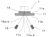
- FIG. 1 is a schematic cross-sectional view of a light source device 1 according to the first embodiment.
- the light source device 1 of the present disclosure includes a sapphire plate 11 having a first surface 11a and a second surface 11b that face each other.
- Sapphire refers to a single crystal of aluminum oxide (chemical formula Al 2 O 3 ).
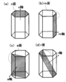
- FIGS. 2A to 2D sapphire has typical crystal planes such as c-plane, m-plane, a-plane, and r-plane. The axes perpendicular to these crystal planes are called the c-axis, m-axis, a-axis, and r-axis, respectively.
- the crystal orientation of the sapphire plate 11 can be specified using an X-ray diffractometer.
- an automatic X-ray crystal orientation measuring device (model 2991F2) manufactured by Rigaku Corporation may be used as the X-ray diffraction device.
- the light source device 1 of the present disclosure includes the wavelength conversion material 13 that faces the first surface 11 a of the sapphire plate 11.
- the light source device 1 of the present disclosure includes the first light source 15 that emits the first excitation light 15a having directivity.
- the first excitation light 15a is applied to the wavelength conversion material 13 through the second surface of the sapphire plate 11.
- the wavelength conversion material 13 converts the wavelength of the irradiated first excitation light 15a into, for example, white light and light for illumination.
- the angle formed between the first surface 11a, the second surface 11b, and the c-axis of sapphire is 0° to 90°, which is the maximum of 90° when orthogonal to the c-axis.
- the angle formed by the first surface 11a, the second surface 11b, and the c-axis of sapphire is larger than 80°, and more preferably larger than 85°.
- the inclination of the first surface 11a and the second surface 11b of the sapphire plate 11 from the c-plane of sapphire is smaller than 10°, more preferably smaller than 5°. This inclination may be 0°. That is, the first surface 11a and the second surface 11b (main surface) of the sapphire plate 11 may be parallel to the c-plane of sapphire, or the main surface may be the c-plane.
- the temperature of the wavelength conversion material 13 and the sapphire plate 11 increases due to a part of the energy of the first excitation light 15a. Since the sapphire plate 11 is plate-shaped, the length in the plane direction is longer than the length in the thickness direction. Therefore, the dimensional change in the plane direction is larger than the dimensional change in the thickness direction. Therefore, if the coefficients of thermal expansion in the plane direction are the same, it is possible to suppress peeling of the wavelength conversion material 13 from the sapphire plate 11 and damage to the wavelength conversion material 13 due to the difference in thermal expansion in the plane direction.
- the thermal expansion coefficient of sapphire from 40°C to 400°C is 7.7 ⁇ 10 -6 /°C in the direction parallel to the c-axis of sapphire and 7.0 ⁇ 10 -6 /°C in the direction perpendicular to the c-axis. Is.
- sapphire is a material having anisotropy in the coefficient of thermal expansion.
- Sapphire has the same coefficient of thermal expansion in any direction perpendicular to the c-axis. Therefore, when the angle formed between the first surface 11a and the second surface 11b of the sapphire plate 11 and the c-axis of sapphire is set to a range larger than 80°, and more preferably larger than 85°, it occurs in the plane direction. The difference in coefficient of thermal expansion can be reduced.
- the angle formed by the c-axis 11c of the sapphire plate 11 and the optical axis 15b of the first excitation light 15a is 20° or more.
- the first excitation light 15a is incident on the second surface 11b of the sapphire plate 11 with an inclination of 20° or more.
- Sapphire is a crystal with birefringence. Birefringence means that when a light ray passes through a substance, it is divided into two rays, normal light and extraordinary light, depending on the polarization state thereof.
- the two types of light have the same refractive index when the light travels coaxially with the optical axis (c-axis) 11c of the sapphire plate 11, and the light is not split into two.
- the refractive index of normal light does not depend on the angle of the light with respect to the optical axis.
- the refractive index of extraordinary light changes depending on the angle of the light with respect to the optical axis 11c.
- the cross section of the excitation light 15a perpendicular to the optical axis 15b is circular
- the cross section perpendicular to the optical axis 15b is circular
- the excitation light 15a is coaxial with the optical axis 11c of the sapphire plate 11.
- the excitation light 15a is divided into a normal light 16a shown by a solid line and an abnormal light 16b shown by a broken line, as shown in FIG. And becomes an approximately elliptical shape.
- the amount of light is larger in the area including both the normal light 16a and the abnormal light 16b than in the area including only the normal light 16a and the area including only the abnormal light 16b. Therefore, a region with a small amount of light is arranged outside the region with a large amount of light. Further, outside the region where the light amount is small, there is a region where the first excitation light 15a is not irradiated.
- a region with a small amount of heat is arranged outside the region with a large amount of heat.
- a region that does not generate heat and is not irradiated with the first excitation light 1a exists on the outside thereof.
- the region not irradiated with light is a region for transmitting and radiating heat generated by the irradiation of light, so that a temperature difference occurs between a region irradiated with light and a region outside thereof. The steeper the temperature difference, the greater the strain generated in the wavelength conversion material 13 and the sapphire plate 11 due to the thermal expansion.
- the first excitation light 15a can be divided into the normal light 16a and the extraordinary light 16b by utilizing the property of the birefringence that the sapphire plate 11 has. Therefore, by disposing a region having a small amount of heat generation outside a region having a large amount of heat generation, the temperature difference generated in the wavelength conversion material 13 and the sapphire plate 11 can be made relatively gentle. As a result, it is possible to prevent the wavelength conversion material 13 from peeling off from the sapphire plate 11.
- the positional deviation between the normal light 16a and the extraordinary light 16b utilizing the birefringence changes depending on the angle between the optical axis 15b of the first excitation light 15a and the c-axis 11c of the sapphire plate 11 and the incident angle.
- Light incident on the second surface 11b of the sapphire plate 11 from the air at an incident angle ⁇ a is refracted at the interface between the air and the sapphire plate 11 (the second surface 11b), and the inside of the sapphire plate 11 is refracted at the refraction angle ⁇ b.
- the refractive index of the sapphire plate 11 is N
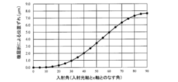
- the first excitation light 15a having a wavelength of 488 nm (the refractive index of normal light is 1.775, the refractive index of extraordinary light is 1) is incident on the second surface 11b of the sapphire plate 11 having a thickness of 3.0 mm as the main surface. .767-1.775) is incident, the positional deviation on the first surface 11a due to the difference in refractive index between the normal light 16a and the extraordinary light 16b is shown in FIG.
- the refractive index of extraordinary light was approximately calculated to change from 1.767 to 1.775 in an elliptic arc shape depending on the incident angle ⁇ a.
- the positional deviation is 0 when the incident angle ⁇ a is 0°, and increases as the incident angle ⁇ a increases, and becomes 0.3 ⁇ m at 20°, 2.0 ⁇ m at 40°, and 15.3 ⁇ m at 90°. .. Therefore, if the angle formed by the c-axis 11c and the optical axis 15b of the first excitation light 15a is 20° or more, and more preferably 40° or more, the position due to the difference in refractive index between the normal light 16a and the extraordinary light 16b is set. The gap will be large, and performance deterioration and damage due to heat are unlikely to occur.
- the incident angle of the first excitation light 15a with respect to the second principal surface 11b may be 75° or less.
- the incident angle is 0° when the first excitation light 15a is vertically incident on the second major surface 11b.
- the proportion of the first excitation light 15a reflected by the second principal surface 11b changes depending on the incident angle of the first excitation light 15a with respect to the second principal surface 11b.
- the reflected portion of the first excitation light 15a does not contribute to light emission. That is, since the luminous efficiency decreases as the reflectance increases, it is necessary to reduce the reflection.
- the graph of FIG. 4 shows the relationship between the reflectance and the incident angle of the first excitation light 15a having a wavelength of 488 nm with respect to the second principal surface 11b when the surface of the sapphire plate 11 is a mirror surface. Since the difference in refractive index between the normal light 16a and the extraordinary light 16b is small, this graph is calculated using only the refractive index of the normal light 16a. The extraordinary light 16b is ignored.
- the graph shows the reflectance of P-polarized light and the reflectance of S-polarized light, and the average value of the reflectance of P-polarized light and the reflectance of S-polarized light.
- the first excitation light 15a is unpolarized natural light
- the relationship between the incident angle of the first excitation light 15a with respect to the second principal surface 11b and the reflectance is the reflectance of P-polarized light and the reflectance of S-polarized light.
- the reflectances of both S-polarized light and P-polarized light are relatively small. Therefore, when the incident angle of the first excitation light 15a with respect to the second principal surface 11b is set to 75° or less, it is possible to suppress the reflection of the first excitation light 15a on the second principal surface 11b and increase the light emission efficiency. Since the reflectance is small when the first excitation light 15a is P-polarized light, it is possible to suppress the reflection of the first excitation light 15a on the second principal surface 11b by setting the incident angle to 85° or less, and to increase the light emission efficiency. it can.
- the incident angle of the first excitation light 15a with respect to the second main surface 11b is 55° or less, the reflectance can be further reduced.
- the first excitation light 15a is P-polarized light, the reflectance is small. Therefore, if the incident angle is 75° or less, it is possible to suppress the reflection of the first excitation light 15a on the second main surface 11b, and to improve the light emission efficiency. Can be higher
- the incident angle of the first excitation light 15a with respect to the second principal surface 11b is 40. It is preferable that the range is up to 55°. When the first excitation light 15a is P-polarized light, the incident angle may be in the range of 40 to 75°.
- the optical axis 15b of the first excitation light 15a is obliquely applied to the second main surface 11b of the sapphire plate 11. Therefore, even if the first excitation light 15a is reflected by the second principal surface 11b, it is possible to prevent the reflected light from being applied to the first light source 15. As a result, damage to the first light source 15 can be suppressed.
- a second excitation light source 17 for irradiating the wavelength conversion material 13 with the second excitation light 17a having directivity through the second surface 11b of the sapphire plate 11 is further provided. Good.
- the pump light sources 15 and 17 are provided in this way, the light amount of the light source device 1 can be increased. A desired amount of light can be obtained even when the first and second excitation light sources 15 and 17 having relatively small amounts of light are combined.
- the second excitation light 17a may be arranged so that at least a part thereof overlaps the first excitation light 15a by the wavelength conversion material 13.
- the area of the wavelength conversion material 13 can be reduced. If the area of the wavelength conversion material 13 can be reduced, the area of contact between the wavelength conversion material 13 and the sapphire plate 11 will be reduced.
- the thermal expansion coefficients of the two are different, the smaller the contact area between the two, the smaller the stress due to the difference in thermal expansion, and the wavelength conversion material 13 can be prevented from peeling from the sapphire plate 11.
- the angle between the c-axis 11c and the optical axis 15b of the first pumping light 15a and the c-axis 11c and the second pumping light are formed.
- the angles formed by 17a and the optical axis 17b may be the same, or may be different as in the third embodiment shown in FIG.
- the first excitation light 15a and the first excitation light 15a It is possible to change the size of the region irradiated with only the normal light and only the abnormal light with the two excitation lights 17a. Therefore, the distribution of the light amount can be appropriately designed by combining these. As shown in FIG.
- the angle between the optical axis 15b of the first excitation light 15a and the optical axis 15b of the second excitation light 17a is in the range of 1° to 179°. May be For example, as in the fourth embodiment shown in FIG. 7, the angle formed by the optical axis 15b of the first excitation light 15a and the optical axis 15b of the second excitation light 17a is 90°, which is in the range of 80° to 100°.
- the temperature difference can be made gentler.
- the light source device 1 of the present disclosure may further include the third excitation light source 19 that emits the third excitation light 19a having directivity, as in the fifth embodiment shown in FIG. With such a configuration, the light amount of the light source device 1 can be further increased.
- the optical axes 15b, 17b, and 19b of the first excitation light 15a, the second excitation light 17a, and the third excitation light 19a are projected on the second surface 11b.
- the angles may be the same, and the angle between them may be 120°.
- the angles formed by the optical axes of the excitation lights 15a, 17a, and 19a with which the wavelength conversion member 13 is irradiated can be made equal intervals.
- the distribution of the temperature difference can be made regular.
- the optical axis 15b of the first excitation light 15a and the optical axis 17b of the second excitation light 17a are asymmetrical with respect to the irradiation position on the second surface 11b of the sapphire plate 11, that is, a plurality of excitations.
- the light sources 15a and 17a may be arranged such that one of the light sources 15a and 17a does not irradiate the other with totally reflected light. Thereby, even if the excitation lights 15a and 17a are reflected by the sapphire plate 11, it is possible to prevent the excitation light sources 15 and 17 from being damaged by being irradiated on the other excitation light sources 15 and 17.
- the excitation light sources 15, 17, and 19 may be laser light sources. Since the laser light emitted from the laser light source has high directivity and high output, the output of the light source device 1 can be increased.
- the excitation light sources 15, 17, and 19 may be LEDs, and a deformable optical fiber may be used to guide the excitation light. With such a configuration, the degree of freedom in designing the light source device 1 increases. In either case, the heat source can be separated by separating the wavelength conversion material 13 serving as a heat source and the excitation light sources 15, 17, 19 from each other, which facilitates heat dissipation.
- the thickness of the sapphire plate 11 is 0.2 mm or more, it can have sufficient mechanical strength as a holding member for the wavelength conversion material 13. In particular, when the thickness of the sapphire plate 11 is 1 mm or more, deformation or damage due to local heat generation due to laser light irradiation is unlikely to occur. When the thickness of the sapphire plate 11 is in the range of 2 mm or more and 4 mm or less, heat dissipation can be increased. As the thickness of the sapphire plate 11 increases, the positional deviation between the normal light 16a and the extraordinary light 16b increases. Therefore, when the thickness of the sapphire plate 11 is set to 2 mm or more, the positional deviation between the normal light 16a and the extraordinary light 16b with which the wavelength conversion material 13 is irradiated can be made relatively large.
- the angle formed by the axis perpendicular to the main surface (the first surface 11a and the second surface 11b) of the sapphire plate 11 and the c-axis 11c of the sapphire plate 11 may be 0.1° or more.
- the first surface 11a and the second surface 11b of the sapphire plate 11 may have an offset angle of 0.1° or more from the c-plane.
- the height numbers of the first surface 11a and the second surface 11b of the sapphire plate 11 are different.
- ⁇ a step structure with a width of several tens to several hundreds ⁇ is formed.
- the larger the offset angle the larger the step height and the smaller the width.
- the offset angle may be 0.5° or more. With such a configuration, a relatively large step structure is formed on the first surface 11a and the second surface 11b of the sapphire plate 11.
- the step structure is sufficiently smaller than the wavelength, so that the influence on the optical characteristics of the light source device 1 is suppressed to an unnoticeable level. ..
- the sapphire plate 11 By performing heat treatment or plasma treatment as a pretreatment for forming a film on the surfaces of the first surface 11a and the second surface 11b of the sapphire plate 11, a step structure having more uniform steps is formed on the main surfaces 11a and 11b. It is easy to occur. With such a step structure, the adhesion strength between the sapphire plate 11 and the film is high, and the dispersion of the adhesion strength is small.
- the sapphire plate 11 may be heat-treated at a temperature of 800° C. or higher, for example, 1000° C. for about 3 hours.
- the excitation light 15a may be condensed into a diameter of 0.5 mm or more and 3 mm or less and applied to the wavelength conversion material 13. In this way, by increasing the light density of the excitation light 15a that enters the wavelength conversion material 13, it is possible to obtain the small-sized and high-luminance light source device 1. Furthermore, it becomes possible to provide a lighting device having an excellent design.
- the light source device 1 may include a dichroic film (not shown) between the sapphire plate 11 and the wavelength conversion material 13 that transmits the excitation light 15a and reflects the wavelength conversion light.
- the second surface 11b of the sapphire plate 11 may be provided with an antireflection film (not shown) that reduces the reflectance of the excitation light 15a.
- the dichroic film and the antireflection film can increase the luminous efficiency of the light source device 1.
- the sapphire plate 11 and the wavelength conversion material 13 may be in direct contact, or may be in indirect contact with a dichroic film or the like interposed therebetween.
- the wavelength conversion material 13 is, for example, a phosphor.
- the wavelength conversion material 13 may be a ceramic phosphor, and with such a structure, the light source device 1 having excellent heat resistance can be obtained.
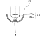
- the lighting device 21 of the present disclosure includes a reflector 23 a that is a light guide member 23 that guides light emitted from the light source device 1 of the present disclosure in a desired direction, and a lens 23 b.
- the light source device 1 is illustrated in a simplified manner.
- the lighting device 21 of the present disclosure is suitable for a spotlight, a headlight for a moving body such as a vehicle, and the like.
- vehicle headlamps traveling headlamps (so-called high beams) are required to have the capability of confirming traffic obstacles 100 m ahead of them at night.
- the light source device 1 and the illumination device 21 of the present disclosure can suppress the deterioration of the wavelength conversion material 13 even when the irradiation distance is 100 m or more, for example, a high light amount of 600 m.
- the light source device 1 may be designed so that the sapphire plate 11 is cooled by the air flow.
- a blower such as a fan may be used to cool the sapphire plate 11 by air.
- An airflow generated as a moving body such as a vehicle moves may be used.
- cooling fins may be connected to the sapphire plate 11. The cooling fins may be formed on at least a part of the portion of the sapphire plate 11 other than the area irradiated with light.
- the sapphire plate 11 When the sapphire plate 11 is one that attenuates light in a predetermined wavelength range such as ultraviolet light among irradiated light, damage to the constituent members of the light source device 1 such as the first excitation light source 15 due to external light is suppressed.
- the average value of the transmittance of the sapphire plate 11 in the wavelength range of 200 to 400 nm may be smaller than the average value of the transmittance in the wavelength range of 400 to 800 nm.
- the sapphire plate 11 satisfies such a configuration, the light in the so-called ultraviolet light region can be attenuated, and damage to the first excitation light source 15 and the like due to the ultraviolet light included in the sunlight that has entered the lighting device 1 can be suppressed. it can.
- the sapphire plate 11 may have an absorption band in the wavelength range of 205 to 260 nm.
- the atmosphere during sapphire crystal growth or during the heat treatment after growth to a reducing atmosphere and introducing defects due to oxygen vacancies into sapphire it has an absorption band in the ultraviolet light region and emits ultraviolet light. Reduced sapphire can be produced.
- Sapphire having defects due to oxygen vacancies has defects called F centers and F+ centers.
- the F center has absorption bands at 205 nm
- the F+ center has absorption bands at 210 nm, 230 nm, and 260 nm.
- the light source device 1 of the present disclosure is suitable for the illumination device 21 for a mobile body that is often exposed to external light such as sunlight.
- the moving body is, for example, a vehicle, and includes ships and airplanes.
Landscapes
- Engineering & Computer Science (AREA)
- General Engineering & Computer Science (AREA)
- Physics & Mathematics (AREA)
- Spectroscopy & Molecular Physics (AREA)
- Optics & Photonics (AREA)
- Non-Portable Lighting Devices Or Systems Thereof (AREA)
- Projection Apparatus (AREA)
Abstract
本開示の光源装置は、対向する第1面と第2面とを有するサファイア板と、該サファイア板の前記第1面に対向して位置する波長変換材と、指向性を有する第1励起光を前記第2面を通じて前記波長変換材に出射する第1励起光源とを備えた光源装置であって、前記第1面および前記第2面とサファイアのc軸とのなす角は80°よりも大きく、前記c軸と前記第1励起光の光軸とのなす角は20°以上である。本開示の照明装置は、前記光源装置と導光部材とを備える。
Description
本開示は、光源装置および照明装置に関する。
近年、LEDや半導体レーザ(LD)を光源とする照明装置が、車両用前照灯などの用途で利用され始めている。この照明装置で使用される光源装置は、蛍光体などの波長変換材に照射された励起光を波長変換して、直接または間接的に白色光を生成するものである。この白色光を反射板やレンズを用いて所望の方向に照射することで、従来の照明装置に比べて光量の大きな照明装置となる。
この波長変換材の変換効率は100%ではなく、照射された励起光のエネルギーの一部は、熱となる。そのため、波長変換材を保持する保持板には、透光性に加え、放熱性能が求められる。
サファイアは、光の透過率と熱伝導率が高く、保持板の材質として優れている。例えば、特許文献1および2には、レーザ光源と、蛍光体と、蛍光体を保持するサファイア板とを備える光源装置および照明装置が記載されており、サファイア板に対して、レーザ光を垂直に照射した例が記載されている。
このような光源装置においては、さらに光量を増大させると、波長変換材の発熱量が増大し、熱により波長変換材が劣化するおそれがある。さらに、発熱部分とその外側の領域の温度差による応力で、波長変換材が損傷するおそれがある。本開示は、熱による性能低下や損傷が起こりにくい光源装置および照明装置を提供することを目的とする。
本開示の光源装置は、対向する第1面と第2面とを有するサファイア板と、サファイア板の第1面に対向して位置する波長変換材と、指向性を有する第1励起光を第2面を通じて波長変換材に出射する第1励起光源とを備える。第1面および第2面と、サファイアのc軸とのなす角は、80°よりも大きく、c軸と、第1励起光の光軸とのなす角は、20°以上である。
本開示の照明装置は、前記光源装置と導光部材とを備える。
本開示によれば、熱による性能低下や損傷が起こりにくい光源装置および照明装置を提供することができる。
本開示の光源装置、およびそれを用いた照明装置について、図を参照しながら説明する。図1は、第1の実施形態に係る光源装置1の断面概略図である。
本開示の光源装置1は、対向する第1面11aと第2面11bとを有するサファイア板11を備えている。サファイアとは、酸化アルミニウム(化学式Al2O3)の単結晶をいう。図2(a)~(d)にそれぞれ示すように、サファイアは代表的な結晶面として、c面、m面、a面、r面等の結晶面を有している。これらの結晶面に垂直な軸を、それぞれc軸、m軸、a軸、r軸という。サファイア板11の結晶方位は、X線回折装置を用いて特定することができる。例えば、X線回折装置として、株式会社リガク製の自動X線結晶方位測定装置(型式2991F2)などを用いればよい。
本開示の光源装置1は、サファイア板11の第1面11aに対向して位置する波長変換材13を備えている。本開示の光源装置1は、指向性を有する第1励起光15aを出射する第1光源15を備えている。第1励起光15aは、サファイア板11の第2面を通じて波長変換材13に照射される。波長変換材13は、照射された第1励起光15aの波長を変換し、例えば、白色光とし、照明のための光とする。
第1面11aと第2面11bとサファイアのc軸とのなす角は、0°から90°であり、c軸と直交する時に最大の90°となる。本開示の光源装置1におけるサファイア板11は、第1面11aと第2面11bとサファイアのc軸とのなす角が、80°よりも大きく、さらに好ましくは85°よりも大きい。言い換えると、サファイア板11の第1面11aと第2面11bとは、サファイアのc面からの傾きが、10°よりも小さく、さらに好ましくは5°よりも小さい。この傾きは0°でもよい。つまり、サファイア板11の第1面11aと第2面11b(主面)とがサファイアのc面に対して平行でもよく、主面がc面でもよい。
第1励起光15aがサファイア板11を通過し、波長変換材13に照射されると、第1励起光15aのエネルギーの一部により、波長変換材13およびサファイア板11の温度が高くなる。サファイア板11は板状であるため、厚み方向の長さよりも、平面方向の長さが長い。したがって、平面方向の寸法変化の方が厚み方向の寸法変化よりも大きくなる。そこで、平面方向の熱膨張係数を同じとすると、平面方向の熱膨張差に起因するサファイア板11からの波長変換材13の剥離や波長変換材13の損傷を抑制することができる。
サファイアの40℃から400℃における熱膨張係数は、サファイアのc軸に平行な方向が7.7×10⁻⁶/℃であり、c軸に垂直な方向が7.0×10-6/℃である。このように、サファイアは、熱膨張係数に異方性を有する材料である。
サファイアは、c軸と垂直な方向では、いずれの方向であっても同じ熱膨張係数を有する。そのため、サファイア板11の第1面11aおよび第2面11bと、サファイアのc軸とのなす角を80°よりも大きい範囲、さらに好ましくは85°よりも大きい範囲とすると、平面方向において発生する熱膨張係数の差を小さくすることができる。
本開示の光源装置1においては、サファイア板11のc軸11cと第1励起光15aの光軸15bとのなす角は、20°以上である。言い換えると、図1に示すように、サファイア板11の第2面11bに対して、第1励起光15aが、20°以上傾いて入射している。
サファイアは複屈折性を有する結晶である。複屈折とは、光線が物質を透過したときに、その偏光の状態によって、正常光と異常光との2つに分けられることをいう。2種類の光の屈折率は、光がサファイア板11の光学軸(c軸)11cと同軸で進行するときは一致し、光が2つに分かれることはない。一方、光の進行方向がサファイア板11の光学軸11cと同軸でない場合には、正常光の屈折率は、光の光学軸に対する角度には依存しない。しかし、異常光の屈折率は、光の光学軸11cに対する角度に依存して変化する。
例えば、光軸15bに対して垂直な励起光15aの断面形状が円形である場合、励起光15aが、サファイア板11の光学軸11cと同軸でなければ、光軸15bに垂直な断面形状が円形の励起光15aは、サファイア板11を通過する過程で、図3に示すように、励起光15aは実線で示す正常光16aと破線で示す異常光16bとに分かれ、2つの円が重なった状態となり、おおよそ楕円の形となる。
このとき、正常光16aのみを含む領域および異常光16bのみを含む領域に比べ、正常光16aと異常光16bの両方を含む領域では、光量が多くなる。したがって、光量の多い領域の外側に光量の少ない領域が配置されることになる。さらに、光量の少ない領域の外側には、第1励起光15aが照射されない領域が存在している。
光量が多いほど、波長変換材13の発熱量が大きくなるため、本開示の光源装置1では、発熱量の大きい領域の外側に発熱量の小さい領域が配置されることになる。その外側に第1励起光1aが照射されず発熱しない領域が存在する。光が照射されない領域は、光の照射により発生した熱を伝達し、放射する領域となるために光が当たる領域と、その外側の領域とで温度差が生じる。この温度差が急峻であるほど、波長変換材13やサファイア板11には、熱膨張に伴い発生したひずみが大きくなる。
本開示の光源装置1では、サファイア板11が有する複屈折性という性質を利用して、第1励起光15aを正常光16aと異常光16bとに分けることができる。そのため、発熱量の大きい領域の外側に発熱量の小さい領域を配置することで、波長変換材13やサファイア板11に生じる温度差を比較的緩やかにすることができる。その結果、波長変換材13がサファイア板11から剥離することを抑制することができる。
この複屈折性を利用した正常光16aと異常光16bとの位置のずれは、第1励起光15aの光軸15bとサファイア板11のc軸11cとのなす角および入射角によって変化する。空気中からサファイア板11の第2面11bに入射角θaで入射した光は、空気とサファイア板11との界面(第2面11b)で屈折して、サファイア板11の中を屈折角θbで伝搬する。サファイア板11の屈折率をNとした時、スネルの法則より、sinθa/sinθb=Nである。この関係を用いて、正常光16aと異常光16bとの位置のずれを計算することができる。
例えば、厚みが3.0mmのc面を主面とするサファイア板11の第2面11bに波長488nmの第1励起光15a(正常光の屈折率は1.775、異常光の屈折率は1.767~1.775)が入射したとき、正常光16aと異常光16bとの屈折率の違いによる第1面11aにおける位置ずれは、図10で表される。図10において異常光の屈折率は、入射角θaに依存して1.767から1.775まで、楕円弧状に変化すると近似計算した。
位置ずれは、入射角θaが0°の時に0で、入射角θaが大きくなるほど大きくなり、入射角θaが20°で0.3μm、40°で2.0μm、90°で15.3μmになる。そこで、c軸11cと、第1励起光15aの光軸15bとのなす角は、20°以上、さらに好ましくは40°以上とすると、正常光16aと異常光16bとの屈折率の違いによる位置ずれが大きくなり、熱による性能低下や損傷が起こりにくい。
第2主面11bに対する第1励起光15aの入射角は、75°以下としてもよい。入射角は、第2主面11bに垂直に第1励起光15aが入射したとき、0°となる。
図4に示すように、第2主面11bに対する第1励起光15aの入射角によって、第1励起光15aが第2主面11bで反射する割合が変化する。第1励起光15aのうち、反射した分は発光に寄与しない。すなわち、反射率が大きくなると発光効率が低下するため、反射を減らすことが求められる。
図4のグラフは、サファイア板11の表面が鏡面である場合の第2主面11bに対する波長488nmの第1励起光15aの入射角と反射率との関係を算出したものである。正常光16aと異常光16bとの屈折率の差は小さいため、このグラフは、正常光16aの屈折率のみを用いて算出したものである。異常光16bについては無視している。
グラフにはP偏光の反射率とS偏光の反射率、P偏光の反射率とS偏光の反射率の平均値を示している。第1励起光15aが、偏光されていない自然光であるとすると、第2主面11bに対する第1励起光15aの入射角と反射率との関係は、P偏光の反射率とS偏光の反射率との平均値で示されることになる。
第2主面11bに対する第1励起光15aの入射角が75°以下の領域では、S偏光およびP偏光ともに比較的、反射率が小さくなっている。そこで、第2主面11bに対する第1励起光15aの入射角を75°以下とすると、第1励起光15aが第2主面11bで反射することを抑制でき、発光効率を高くできる。第1励起光15aがP偏光である場合は反射率が小さいため、入射角を85°以下とすると、第1励起光15aが第2主面11bで反射することを抑制でき、発光効率を高くできる。第2主面11bに対する第1励起光15aの入射角を55°以下とすると、さらに反射率を小さくできる。第1励起光15aがP偏光である場合は、反射率が小さいため、入射角を75°以下とすると、第1励起光15aが第2主面11bで反射することを抑制でき、発光効率を高くできる。
正常光16aと異常光16bとの位置のずれと、第1励起光15aが第2主面11bで反射することを考慮すると、第2主面11bに対する第1励起光15aの入射角は、40~55°の範囲とするとよい。第1励起光15aがP偏光である場合は、入射角は、40~75°の範囲とするとよい。
本開示の光源装置1は、サファイア板11の第2主面11bに対して、第1励起光15aの光軸15bが斜めに照射される。そのため、第1励起光15aが第2主面11bで反射したとしても、その反射光が第1光源15に照射されることを避けることが可能となる。その結果、第1光源15の損傷を抑制することができる。
図5に示す第2の実施形態のように、指向性を有する第2励起光17aを、サファイア板11の第2面11bを通じて波長変換材13に照射する第2励起光源17をさらに備えていてもよい。このように複数の励起光源15、17を有すると、光源装置1の光量を増加させることができる。比較的、光量の小さな第1および第2励起光源15、17を組み合わせた場合でも、所望の光量を得ることができる。
この第2励起光17aは、第1励起光15aとは、少なくとも一部が波長変換材13で重なるように配置してもよい。励起光同士が重なるようにすると、波長変換材13の面積を小さくすることができる。波長変換材13の面積を小さくできると、波長変換材13とサファイア板11とが接触する面積が小さくなる。両者の熱膨張係数が異なる場合、両者の接触面積が小さいほど、熱膨張差に起因する応力が小さくなり、波長変換材13がサファイア板11から剥離することを抑制することができる。
光源装置1が、複数の励起光源15、17を有する場合、図5に示すように、c軸11cと第1励起光15aの光軸15bとのなす角と、c軸11cと第2励起光17aの光軸17bとのなす角は同じであってもよく、図6に示す第3の実施形態のように異なっていてもよい。
c軸11cと第1励起光15aの光軸15bとのなす角と、c軸11cと第2励起光17aの光軸17bとのなす角とが異なるようにすると、第1励起光15aと第2励起光17aとで正常光のみ、異常光のみが照射される領域の大きさを変えることができる。そのため、これらを組み合わせて、光量の分布を適宜、設計することができる。図6に示すように、第1励起光15aの光軸15bとc軸11cとのなす角度が20°以上であれば、第2励起光17aの光軸17bとc軸とのなす角度が0°であっても構わない。
サファイア板11の第2面11bに垂直な方向から見たとき、第1励起光15aの光軸15bと第2励起光17aの光軸15bとのなす角が、1°以上179°以下の範囲としてもよい。例えば、図7に示す第4の実施形態のように、第1励起光15aの光軸15bと第2励起光17aの光軸15bとのなす角を80°~100°の範囲である90°として第1励起光15aと第2励起光17aが波長変換材13で重なるようにすると、左右方向、上下方向の双方に、正常光のみ、異常光のみが照射される領域を配置することができる。その結果、より温度差を緩やかにすることができる。
本開示の光源装置1においては、図8に示す第5の実施形態のように、指向性を有する第3励起光19aを出射する第3励起光源19をさらに有していてもよい。このような構成とすると、光源装置1の光量をさらに増加させることができる。第2面11bに垂直な方向から見たとき、第1励起光15a、第2励起光17aおよび第3励起光19aのそれぞれの光軸15b、17b、19bを、第2面11bに投影したときのそれぞれの間の角度を同じとし、間の角度を120°としてもよい。このような構成とすると、波長変換部材13に照射される励起光15a、17a、19aの光軸同士のなす角を等間隔とすることができる。その結果、温度差の分布を規則性のあるものとすることができる。
光源装置1は、第1励起光15aの光軸15bと、第2励起光17aの光軸17bとはサファイア板11の第2面11bにおける照射位置に対して非対称な方向、つまり、複数の励起光源15a、17aは、お互いに一方の全反射光が他方に照射されないように配置されていてもよい。これにより、励起光15a、17aがサファイア板11で反射しても、他の励起光源15、17に照射されて励起光源15、17が損傷することを抑制できる。
本開示の光源装置1においては、励起光源15、17、19をレーザ光源としてもよい。レーザ光源から出射されるレーザ光は、指向性が高く、出力も高いため、光源装置1の出力を大きくすることができる。励起光源15、17、19をLEDとしてもよく、変形自在な光ファイバーを用いて、励起光を誘導してもよい。このような構成であると光源装置1の設計の自由度が大きくなる。いずれも発熱源となる波長変換材13と励起光源15、17、19との距離を離すことで熱源を離すことができ、放熱が容易となる。
サファイア板11の厚みは0.2mm以上であれば、波長変換材13の保持部材として充分な機械的強度を有することができる。特にサファイア板11の厚みが1mm以上であれば、レーザ光照射による局所的な発熱による変形や破損が生じにくい。サファイア板11の厚みを2mm以上4mm以下の範囲とすると放熱性を大きくすることができる。サファイア板11の厚みが厚くなると正常光16aと異常光16bとの位置のずれは大きくなる。そのため、サファイア板11の厚みを2mm以上とすると、波長変換材13に照射される正常光16aと異常光16bの位置のずれを比較的大きくすることができる。
サファイア板11の主面(第1面11aおよび第2面11b)に垂直な軸と、サファイア板11のc軸11cとのなす角度を0.1°以上としてもよい。言い換えると、サファイア板11の第1面11a、第2面11bが、c面から0.1°以上のオフセット角を有していてもよい。
サファイア板11の第1面11a、第2面11bが、c面から0.1°以上のオフセット角を有していると、サファイア板11の第1面11a、第2面11bに高さ数Å、幅数10~数100Å程度のステップ構造が形成される。オフセット角が大きいほどステップの高さは大きく、幅は小さくなる。ステップ構造を大きくするために、オフセット角を0.5°以上としてもよい。このような構成とすると、サファイア板11の第1面11a、第2面11bに比較的大きなステップ構造が形成される。
サファイア板11の第1面11aおよび第2面11bがこのようなステップ構造を有すると、後述する反射防止膜、ダイクロイック膜、波長変換材13の形成工程で、これらの膜がステップ部に吸着しやすい。そのため、均一な製膜が可能となり、アンカー効果によりサファイア板11と膜との密着力が向上する。その結果、サファイア板11が加熱および冷却を繰り返しても、これらの膜が剥がれることを抑制することができる。
ステップ構造は、励起光15aが、例えば、460nm程度の青色の波長を有する場合、その波長と比べて充分小さいので、光源装置1の光学的特性への影響は知覚し得ない程度に抑制される。
サファイア板11の第1面11aおよび第2面11bの表面に膜を形成するための前処理として熱処理やプラズマ処理を施すことで、主面11a、11bに、より均一な段差を有するステップ構造が生じやすい。このようなステップ構造によってサファイア板11と膜との密着強度が高く、さらに密着強度のばらつきも小さくなる。例えば、前処理としてサファイア板11を800℃以上の温度、例えば1000℃で3時間程度熱処理するとよい。
励起光15aは、0.5mm以上3mm以下程度の径に集光して波長変換材13に照射するとよい。このように、波長変換材13に入射する励起光15aの光密度を高めることで、小型で高輝度の光源装置1を得ることができる。さらに、デザイン性に優れた照明装置とすることが可能になる。
光源装置1は、サファイア板11と波長変換材13との間に、励起光15aを透過し、波長変換光を反射する、ダイクロイック膜(図示せず)を備えているとよい。サファイア板11の第2面11bに、励起光15aの反射率を低減させる、反射防止膜(図示せず)を備えていてもよい。ダイクロイック膜および反射防止膜は、光源装置1の発光効率を高めることができる。
サファイア板11と波長変換材13とは、直接接触していてもよく、間にダイクロイック膜等を挟んで間接的に接触していてもよい。波長変換材13は、例えば蛍光体である。特に波長変換材13は、セラミック蛍光体であってもよく、このような構成であれば、耐熱性に優れた光源装置1となる。
図9に示すように、本開示の照明装置21は、本開示の光源装置1が発する光を所望の方向に誘導する導光部材23である反射板23aやレンズ23bを有する。図9においては、光源装置1を簡略化して記載した。本開示の照明装置21は、スポットライト、車両などの移動体用前照灯などに好適である。車両用前照灯のうち、特に走行用前照灯(いわゆるハイビーム)は、夜間にその前方100mの距離にある交通上の障害物を確認できる性能を有することが求められる。本開示の光源装置1および照明装置21は、照射距離が100m以上、例えば600mの高い光量としても、波長変換材13の劣化を抑制することができる。
光源装置1は、サファイア板11が気流により冷却されるように設計してもよい。気流による冷却は、サファイア板11を空冷するためにファンなどの送風体を用いればよい。車両などの移動体の移動に伴って生じる気流を利用してもよい。冷却効果を向上させるため、サファイア板11に冷却フィンを接続してもよい。冷却フィンは、サファイア板11の光が照射される範囲以外の部分の少なくとも一部に、形成されていればよい。
サファイア板11として、照射した光のうち、紫外光など所定の波長領域の光を減衰するものを用いると、外光による第1励起光源15などの光源装置1の構成部材の損傷を抑制することができる。例えば、サファイア板11の200~400nmの波長領域における透過率の平均値が、400~800nmの波長領域における透過率の平均値よりも小さくてもよい。サファイア板11がこのような構成を満たすときには、いわゆる紫外光領域の光を減衰させ、照明装置1内に侵入した太陽光に含まれる紫外光による第1励起光源15などの損傷を抑制することができる。
サファイア板11は、205~260nmの波長領域に吸収帯を有していてもよい。サファイアの結晶育成時または、育成後の熱処理時の雰囲気を還元製雰囲気に制御して、酸素空孔に起因する欠陥をサファイアに導入することで、紫外光領域に吸収帯を持ち、紫外光を減少させられるサファイアを製造することができる。酸素空孔に起因する欠陥を有するサファイアは、FセンターおよびF+センターと呼ばれる欠陥を有している。Fセンターは205nm、F+センターは210nm、230nm、260nmに吸収帯を持っている。このような205nm~260nmの波長領域に吸収帯を有するサファイア板11を用いると、光源装置1の内部に侵入する紫外光を減衰させることができる。
このように、本開示の光源装置1は、太陽光などの外部光に曝されることの多い移動体用の照明装置21に好適である。移動体とは、例えば車両であり、船舶や飛行機なども含む。
以上、本開示の光源装置1およびそれを用いた照明装置21の実施形態について説明したが、本開示は上述の実施形態に限定されず、本開示の要旨を逸脱しない範囲において、各種の改良および変更を行なってもよい。
1 光源装置
11 サファイア板
11a 第1面
11b 第2面
11c c軸
13 波長変換材
15 第1励起光源
15a 第1励起光
15b 第1励起光の光軸
16a 正常光
16b 異常光
17 第2励起光源
17a 第2励起光
17b 第2励起光の光軸
19 第3励起光源
19a 第3励起光
19b 第3励起光の光軸
21 照明装置
23 導光部材
23a 反射板
23b レンズ
11 サファイア板
11a 第1面
11b 第2面
11c c軸
13 波長変換材
15 第1励起光源
15a 第1励起光
15b 第1励起光の光軸
16a 正常光
16b 異常光
17 第2励起光源
17a 第2励起光
17b 第2励起光の光軸
19 第3励起光源
19a 第3励起光
19b 第3励起光の光軸
21 照明装置
23 導光部材
23a 反射板
23b レンズ
Claims (10)
- 対向する第1面と第2面とを有するサファイア板と、
該サファイア板の前記第1面に対向して位置する波長変換材と、
指向性を有する第1励起光を前記第2面を通じて前記波長変換材に出射する第1励起光源とを備えた光源装置であって、
前記第1面および前記第2面とサファイアのc軸とのなす角は、80°よりも大きく、
前記c軸と前記第1励起光の光軸とのなす角は、20°以上である光源装置。 - 前記c軸と前記第1励起光の光軸とのなす角は、40°以上である請求項1に記載の光源装置。
- 前記第2主面に対する前記第1励起光の入射角は、75°以下である請求項1または請求項2に記載の光源装置。
- 前記第2主面に対する前記第1励起光の入射角は、55°以下である請求項3に記載の光源装置。
- 指向性を有する第2励起光を前記第2面を通じて前記波長変換材に出射する第2励起光源をさらに備え、前記第1励起光と前記第2励起光とは、少なくとも一部が前記波長変換材で重なる請求項1~4のいずれかに記載の光源装置。
- 前記c軸と前記第1励起光の光軸とのなす角と、前記c軸と前記第2励起光の光軸とのなす角は、異なっている請求項5に記載の光源装置。
- 前記第2面に垂直な方向から見たとき、前記第1励起光の光軸と前記第2励起光の光軸とのなす角度が80°以上100°以下である請求項5または6に記載の光源装置。
- 前記サファイア板と前記波長変換材との間に、前記励起光を透過し、前記波長変換材から出射する波長変換光を反射する、ダイクロイック膜を備える、請求項1~7のいずれかに記載の光源装置。
- 前記サファイア板の前記第2面に、前記励起光の反射率を低減させる、反射防止膜を備える、請求項1~8のいずれかに記載の光源装置。
- 請求項1~9のいずれかに記載の光源装置と、導光部材とを備えた照明装置。
Priority Applications (2)
| Application Number | Priority Date | Filing Date | Title |
|---|---|---|---|
| JP2020557685A JP7194198B2 (ja) | 2018-11-26 | 2019-11-22 | 光源装置および照明装置 |
| US17/296,146 US11280477B2 (en) | 2018-11-26 | 2019-11-22 | Light source device and lighting device |
Applications Claiming Priority (2)
| Application Number | Priority Date | Filing Date | Title |
|---|---|---|---|
| JP2018-220457 | 2018-11-26 | ||
| JP2018220457 | 2018-11-26 |
Publications (1)
| Publication Number | Publication Date |
|---|---|
| WO2020110962A1 true WO2020110962A1 (ja) | 2020-06-04 |
Family
ID=70853989
Family Applications (1)
| Application Number | Title | Priority Date | Filing Date |
|---|---|---|---|
| PCT/JP2019/045870 Ceased WO2020110962A1 (ja) | 2018-11-26 | 2019-11-22 | 光源装置および照明装置 |
Country Status (3)
| Country | Link |
|---|---|
| US (1) | US11280477B2 (ja) |
| JP (1) | JP7194198B2 (ja) |
| WO (1) | WO2020110962A1 (ja) |
Cited By (1)
| Publication number | Priority date | Publication date | Assignee | Title |
|---|---|---|---|---|
| EP4488023A2 (en) | 2017-09-26 | 2025-01-08 | Belron International Limited | Curing repair resin |
Citations (2)
| Publication number | Priority date | Publication date | Assignee | Title |
|---|---|---|---|---|
| JP2017054785A (ja) * | 2015-09-11 | 2017-03-16 | 日立マクセル株式会社 | 光源装置 |
| JP2018181711A (ja) * | 2017-04-18 | 2018-11-15 | パナソニックIpマネジメント株式会社 | 蛍光体ホイール、及び、照明装置 |
Family Cites Families (11)
| Publication number | Priority date | Publication date | Assignee | Title |
|---|---|---|---|---|
| JP4991001B2 (ja) * | 2009-12-28 | 2012-08-01 | シャープ株式会社 | 照明装置 |
| JP5445349B2 (ja) | 2010-06-24 | 2014-03-19 | セイコーエプソン株式会社 | 光源装置及びプロジェクター |
| DE102010034054A1 (de) * | 2010-08-11 | 2012-02-16 | Schott Ag | Laserbasierte Weißlichtquelle |
| JP5656290B2 (ja) * | 2011-03-18 | 2015-01-21 | スタンレー電気株式会社 | 半導体発光装置 |
| GB2497950A (en) * | 2011-12-22 | 2013-07-03 | Sharp Kk | Laser and Phosphor Based Light Source for Improved Safety |
| JP5995541B2 (ja) | 2012-06-08 | 2016-09-21 | Idec株式会社 | 光源装置および照明装置 |
| JP6136744B2 (ja) | 2013-08-15 | 2017-05-31 | ソニー株式会社 | 光源装置、及び画像表示装置 |
| JP6538178B2 (ja) | 2015-09-03 | 2019-07-03 | シャープ株式会社 | 発光装置 |
| JP6457099B2 (ja) | 2015-09-08 | 2019-01-23 | シャープ株式会社 | 波長変換部材および発光装置 |
| DE102015220948A1 (de) * | 2015-10-27 | 2017-04-27 | Osram Gmbh | Beleuchtungsvorrichtung mit Pumpstrahlungsquelle |
| WO2017208572A1 (ja) | 2016-05-30 | 2017-12-07 | ソニー株式会社 | 画像表示装置、及び光源装置 |
-
2019
- 2019-11-22 US US17/296,146 patent/US11280477B2/en active Active
- 2019-11-22 JP JP2020557685A patent/JP7194198B2/ja not_active Ceased
- 2019-11-22 WO PCT/JP2019/045870 patent/WO2020110962A1/ja not_active Ceased
Patent Citations (2)
| Publication number | Priority date | Publication date | Assignee | Title |
|---|---|---|---|---|
| JP2017054785A (ja) * | 2015-09-11 | 2017-03-16 | 日立マクセル株式会社 | 光源装置 |
| JP2018181711A (ja) * | 2017-04-18 | 2018-11-15 | パナソニックIpマネジメント株式会社 | 蛍光体ホイール、及び、照明装置 |
Cited By (2)
| Publication number | Priority date | Publication date | Assignee | Title |
|---|---|---|---|---|
| EP4488023A2 (en) | 2017-09-26 | 2025-01-08 | Belron International Limited | Curing repair resin |
| EP4488022A2 (en) | 2017-09-26 | 2025-01-08 | Belron International Limited | Curing repair resin |
Also Published As
| Publication number | Publication date |
|---|---|
| US11280477B2 (en) | 2022-03-22 |
| JP7194198B2 (ja) | 2022-12-21 |
| US20220018519A1 (en) | 2022-01-20 |
| JPWO2020110962A1 (ja) | 2021-10-07 |
Similar Documents
| Publication | Publication Date | Title |
|---|---|---|
| US10465873B2 (en) | Light emitting device, vehicle headlamp, illumination device, and laser element | |
| CN102537806B (zh) | 发光装置、车辆用前照灯和照明装置 | |
| CN1165785C (zh) | 用于产生一总体上为偏振光束的偏振装置 | |
| CN102187478B (zh) | 发光模块、发光模块的制造方法及灯具单元 | |
| US20100314650A1 (en) | Light emitting module and method of manufacturing the same | |
| CN1306626A (zh) | 用于产生-总体上为偏振光束的偏振装置 | |
| JP6271216B2 (ja) | 発光ユニットおよび照明装置 | |
| JP2023067918A (ja) | 発光装置、及び、光学装置 | |
| KR20210025643A (ko) | 광원 장치 | |
| CN108681198B (zh) | 一种光源装置以及投影显示装置 | |
| WO2014080705A1 (ja) | 発光装置およびその製造方法、照明装置、ならびに前照灯 | |
| US10281638B2 (en) | Wavelength converting module and light-source module applying the same | |
| WO2017183606A1 (ja) | 蛍光体素子および照明装置 | |
| JP7194198B2 (ja) | 光源装置および照明装置 | |
| JP5737861B2 (ja) | 照明装置及び車両用前照灯 | |
| JP7163408B2 (ja) | 光源装置および照明装置 | |
| JP6905070B2 (ja) | 光源装置および照明装置 | |
| CN114585968A (zh) | 光源装置、图像投影装置和光源光学系统 | |
| CN106895271B (zh) | 一种照明装置及车辆用前照灯装置 | |
| JP2018503211A (ja) | 発光デバイス | |
| CN112859499B (zh) | 光源装置和投影仪 | |
| JP6072447B2 (ja) | 照明装置及び車両用前照灯 | |
| CN113835285A (zh) | 光源结构及投影设备 | |
| US20230077284A1 (en) | Rotation wheel and projection apparatus | |
| WO2011078008A1 (ja) | 車両用前照灯 |
Legal Events
| Date | Code | Title | Description |
|---|---|---|---|
| 121 | Ep: the epo has been informed by wipo that ep was designated in this application |
Ref document number: 19889578 Country of ref document: EP Kind code of ref document: A1 |
|
| ENP | Entry into the national phase |
Ref document number: 2020557685 Country of ref document: JP Kind code of ref document: A |
|
| NENP | Non-entry into the national phase |
Ref country code: DE |
|
| 122 | Ep: pct application non-entry in european phase |
Ref document number: 19889578 Country of ref document: EP Kind code of ref document: A1 |