WO2020110541A1 - 電気機器システム - Google Patents
電気機器システム Download PDFInfo
- Publication number
- WO2020110541A1 WO2020110541A1 PCT/JP2019/041961 JP2019041961W WO2020110541A1 WO 2020110541 A1 WO2020110541 A1 WO 2020110541A1 JP 2019041961 W JP2019041961 W JP 2019041961W WO 2020110541 A1 WO2020110541 A1 WO 2020110541A1
- Authority
- WO
- WIPO (PCT)
- Prior art keywords
- battery
- control unit
- battery pack
- side control
- signal terminal
- Prior art date
- Legal status (The legal status is an assumption and is not a legal conclusion. Google has not performed a legal analysis and makes no representation as to the accuracy of the status listed.)
- Ceased
Links
Images



Classifications
-
- H—ELECTRICITY
- H01—ELECTRIC ELEMENTS
- H01M—PROCESSES OR MEANS, e.g. BATTERIES, FOR THE DIRECT CONVERSION OF CHEMICAL ENERGY INTO ELECTRICAL ENERGY
- H01M10/00—Secondary cells; Manufacture thereof
- H01M10/42—Methods or arrangements for servicing or maintenance of secondary cells or secondary half-cells
- H01M10/48—Accumulators combined with arrangements for measuring, testing or indicating the condition of cells, e.g. the level or density of the electrolyte
-
- H—ELECTRICITY
- H01—ELECTRIC ELEMENTS
- H01M—PROCESSES OR MEANS, e.g. BATTERIES, FOR THE DIRECT CONVERSION OF CHEMICAL ENERGY INTO ELECTRICAL ENERGY
- H01M10/00—Secondary cells; Manufacture thereof
- H01M10/42—Methods or arrangements for servicing or maintenance of secondary cells or secondary half-cells
- H01M10/44—Methods for charging or discharging
-
- H—ELECTRICITY
- H02—GENERATION; CONVERSION OR DISTRIBUTION OF ELECTRIC POWER
- H02J—ELECTRIC POWER NETWORKS; CIRCUIT ARRANGEMENTS OR SYSTEMS FOR SUPPLYING OR DISTRIBUTING ELECTRIC POWER; SYSTEMS FOR STORING ELECTRIC ENERGY
- H02J7/00—Circuit arrangements for charging or discharging batteries or for supplying loads from batteries
-
- H—ELECTRICITY
- H02—GENERATION; CONVERSION OR DISTRIBUTION OF ELECTRIC POWER
- H02J—ELECTRIC POWER NETWORKS; CIRCUIT ARRANGEMENTS OR SYSTEMS FOR SUPPLYING OR DISTRIBUTING ELECTRIC POWER; SYSTEMS FOR STORING ELECTRIC ENERGY
- H02J7/00—Circuit arrangements for charging or discharging batteries or for supplying loads from batteries
- H02J7/02—Circuit arrangements for charging or discharging batteries or for supplying loads from batteries for charging batteries from AC mains by converters
-
- Y—GENERAL TAGGING OF NEW TECHNOLOGICAL DEVELOPMENTS; GENERAL TAGGING OF CROSS-SECTIONAL TECHNOLOGIES SPANNING OVER SEVERAL SECTIONS OF THE IPC; TECHNICAL SUBJECTS COVERED BY FORMER USPC CROSS-REFERENCE ART COLLECTIONS [XRACs] AND DIGESTS
- Y02—TECHNOLOGIES OR APPLICATIONS FOR MITIGATION OR ADAPTATION AGAINST CLIMATE CHANGE
- Y02E—REDUCTION OF GREENHOUSE GAS [GHG] EMISSIONS, RELATED TO ENERGY GENERATION, TRANSMISSION OR DISTRIBUTION
- Y02E60/00—Enabling technologies; Technologies with a potential or indirect contribution to GHG emissions mitigation
- Y02E60/10—Energy storage using batteries
Definitions
- the present invention relates to an electric device system including a battery pack having a control unit and an electric device body to which the battery pack can be connected.
- Patent Document 1 discloses a charging system in which a battery pack having a control unit (microcomputer) is charged by a charging device.
- Patent Document 1 since the control unit of the battery pack is always activated, the power of the battery pack is wasted. Further, if a dedicated terminal for activating the control unit of the battery pack is provided, the number of terminals increases, which leads to an increase in size of the battery pack and the main body of the electric device. Further, in order to save the number of terminals, if the terminal for activating the control unit of the battery pack is provided with another function, if the control unit of the battery pack is unnecessarily activated for another function, the battery pack Useless power consumption.
- the present invention has been made in view of these circumstances, and an object thereof is to provide an electric device system capable of suppressing the power consumption of a battery pack. Another object is to provide an electric device system with a reduced number of terminals. Still another object is to provide an electric device system capable of suppressing an increase in power consumption of a battery pack while reducing the number of terminals.
- This electric device system includes a battery pack including battery cells and a battery-side control unit, and an electric device main body that includes a device-side control unit and is connectable to the battery pack, and the device-side control unit includes the battery. It has a first mode that operates when the side control unit is not activated, and a second mode that operates when the battery side control unit is activated.
- the battery pack includes a battery-side signal terminal
- the electric device body includes a device-side signal terminal connectable to the battery-side signal terminal
- the device-side control unit includes the battery-side signal terminal and the device-side signal terminal. It is configured to send a start signal for starting the battery side control unit to the battery pack via the, the device side control unit, in a state in which the battery side control unit is not activated, information of the battery pack, A signal indicating the state or the presence/absence of connection may be obtainable via the battery side signal terminal and the device side signal terminal.
- the device side control unit may switch the first and second modes using the battery side signal terminal and the device side signal terminal.
- the first mode is a battery connection detection mode that detects whether or not the battery pack is connected to the electric device body
- the second mode is a device-side control unit and a battery-side control unit. It may be a communication mode in which communication is performed between them.
- a switching circuit that is connected to the device-side signal terminal and is capable of switching between the first mode and the second mode is provided, and the electric device body outputs the activation signal when the switching circuit switches to the second mode. It may be controlled to do so.
- the switching circuit includes first and second resistors having different resistance values, one end of which is connected to the device-side signal terminal, and a selection circuit which selects and connects one of the first and second resistors.
- the device-side control unit may switch the selection of the first and second resistors by the selection circuit when switching between the first and second modes by the switching circuit.
- the device-side signal terminal becomes a first level voltage at which the battery-side control unit does not start, and when the selection circuit selects the second resistance, the battery-side control is performed. It may be a second level voltage at which the unit is activated.
- the battery pack has a third resistor whose one end is connected to the battery-side signal terminal and whose other end is connected to the ground potential, and which corresponds to the connection state of the first and second resistors and the third resistor.
- the voltage of the device-side signal terminal may be switched.
- the device-side control unit may temporarily switch to a voltage of the first level when the voltage of the device-side signal terminal is at the second level.
- the electric device main body may be a charging device, and the device-side control unit may charge the battery pack in the second mode, and transition to the first mode when charging of the battery pack is completed. ..
- the device-side control unit may temporarily switch to the first mode while charging the battery pack in the second mode.
- the battery-side control unit may operate by receiving power supply from the battery cell.
- the battery pack may include a start-up circuit that receives the start-up signal and starts the battery-side controller.
- the start-up circuit may maintain the driving state of the battery-side control unit by a signal from the battery-side control unit when the battery-side control unit is started.
- This electric device system includes a battery pack having battery cells and a battery-side control unit, and a charging device to which the battery pack is connected, and the battery pack provides a start signal for starting the battery-side control unit.
- a battery side signal terminal for receiving from the charging device, and an element for indicating information, a state or presence/absence of connection of the battery pack, which is connected to the battery side signal terminal, wherein the charging device is on a device side.
- a control unit and a device-side signal terminal connected to the battery-side signal terminal for transmitting the activation signal to the battery pack, wherein the device-side control unit is activated by the battery-side control unit.
- a signal indicating the information of the battery pack, the state, or the presence or absence of connection can be acquired from the device side signal terminal.
- an electric device system capable of suppressing the power consumption of a battery pack. Further, it is possible to provide an electric device system with a reduced number of terminals. Further, it is possible to provide an electric device system capable of suppressing an increase in power consumption of a battery pack while reducing the number of terminals.
- the circuit block diagram of the electric equipment system (charging system) 1 which concerns on embodiment of this invention.
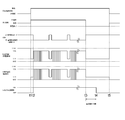
- the time chart which shows an example of operation of electric equipment system (charging system) 1.
- the flowchart of operation of the standby mode of the charging device 10. 6 is a flowchart of the operation of the charging device 10 in the charging mode. 6 is a flowchart of the operation of the charging device 10 in the charging end mode.
- FIG. 1 is a circuit block diagram of an electric device system (charging system) 1 according to an embodiment of the present invention.
- the electric device system (charging system) 1 includes a charging device 10 serving as an electric device main body and a battery pack 50.
- the charging device 10 includes a device-side plus terminal 21, a device-side D terminal 22 as a device-side signal terminal, a device-side LD terminal 23 as a device-side informing terminal, and a device-side for connection with the battery pack 50.
- a negative terminal 24 includes a battery side positive terminal (charging positive terminal) 61, a battery side D terminal 62 as a battery side signal terminal, a battery side LD terminal 63 as a battery side notification terminal, and a battery side negative terminal 64.
- the battery pack 50 may have a discharging positive terminal separately from the battery-side positive terminal 61 or may be a common terminal.
- the device-side plus terminal 21 and the battery-side plus terminal 61 are connected to each other.
- the device-side D terminal 22 and the battery-side D terminal 62 are connected to each other.
- the device-side LD terminal 23 and the battery-side LD terminal 63 are connected to each other.
- the device-side negative terminal 24 and the battery-side negative terminal 64 are connected to each other.
- the charging device 10 includes a power supply circuit 11, a control unit (device-side control unit) 13, a communication circuit 15, a switching circuit 17, and a switch 19.
- the power supply circuit 11 converts an AC voltage supplied from an external AC power supply 5 such as a commercial power supply into a DC voltage for charging the battery pack 50 and outputs the DC voltage to the device-side plus terminal 21, and controls the AC voltage.
- the DC voltage is converted to the DC voltage VDD2 and is supplied to each circuit of the charging device 10.
- the control unit 13 controls the overall operation of the charging device 10.
- the communication circuit 15 is connected to the device-side D terminal 22 and transmits/receives a communication signal to/from the communication circuit 57 of the battery pack 50 under the control of the control unit 13.
- the switch 19 is, for example, a relay and is opened/closed under the control of the control unit 13.
- the charging device 10 has a resistor R5 in the charging current path.
- the control unit 13 detects the charging current based on the voltage across the resistor R5.
- the control unit 13 detects the voltage of the battery pack 50 based on the voltage of the device-side positive terminal 21.
- the switching circuit 17 has a first resistor R1, a second resistor R2, and a selection switch SW4 that serves as a selection circuit.
- One ends of the first resistor R1 and the second resistor R2 are connected to the device-side D terminal 22.
- the other ends of the first resistor R1 and the second resistor R2 are connected to one end of the selection switch SW4.
- the other end of the selection switch SW4 is connected to the power supply line to which the power supply voltage VDD2 is supplied.
- the resistance value of the first resistor R1 is larger than the resistance value of the second resistor R2.
- the selection switch SW4 switches which of the first resistor R1 and the second resistor R2 is connected to the power supply line.
- the selection switch SW4 can be configured by a switching element such as FET.
- the voltage of the device-side D terminal 22 is a voltage level obtained by dividing the power supply voltage VDD2 by the first resistor R1 and the discrimination resistor R3 of the battery pack 50.
- a voltage level (VD1 in FIG. 2) that is higher than the ground potential (0V) and cannot turn on the switching element SW2 described later of the battery pack 50.
- the selection switch SW4 connects the second resistor R2 to the power supply line
- the voltage of the device-side D terminal 22 is a voltage level obtained by dividing the power supply voltage VDD2 by the second resistor R2 and the discrimination resistor R3 of the battery pack 50.
- the control unit 13 controls the selection switch SW4 to select the first resistor R1, and the battery pack 50 is connected by the voltage VD1 of the device-side D terminal 22 at that time. That is, the information regarding the type of the battery pack 50 (rated voltage, number of connected cells, connection form of cells, etc.) is acquired.
- the control unit 13 controls the selection switch SW4 to select the second resistor R2 and turns on the switch SW2 of the battery pack 50. Then, as described later, the control unit 53 of the battery pack 50 is activated. After that, the communication circuit 15 communicates with the communication circuit 57 of the battery pack 50.
- the battery pack 50 includes a power supply circuit 51, a control unit (battery-side control unit) 53, a battery cell group 55, a communication circuit 57, a connection detection circuit 59, a temperature detection element 67, and a switching circuit 69.
- the power supply circuit 51 converts the output voltage of the battery cell group 55 into a control DC voltage VDD1 and supplies it to each circuit of the battery pack 50.
- the control unit 53 controls the overall operation of the battery pack 50.
- the battery cell group 55 has a plurality of battery cells.
- the communication circuit 57 is connected to the battery side D terminal 62, and transmits/receives a communication signal to/from the communication circuit 15 of the charging device 10 under the control of the control unit 53.
- the connection detection circuit 59 is connected to the battery-side D terminal 62, and detects whether the charging device 10 or another electric device body is connected.
- the battery pack 50 has a determination resistor R3 between the battery side D terminal 62 and the ground.
- the determination resistor R3 is an example of an element for indicating the information of the battery pack 50 and the presence or absence of connection.
- the resistance value of the determination resistor R3 is a value corresponding to the information of the battery pack 50 (rated voltage, number of connected cells, connection form of cells, etc.).
- the temperature detection element 67 is, for example, a thermistor, is arranged near the battery cell group 55, and detects the temperature of the battery cell group 55. Note that the temperature of one of the battery cells may be detected.
- the control unit 53 monitors the voltage of each cell of the battery cell group 55.
- the control unit 53 also monitors the temperature of the battery cell group 55.
- the battery pack 50 has a resistor R4 in the discharge current path.
- the control unit 53 detects the discharge current based on the voltage across the resistor R4.
- the switching circuit 69 serving as a starting circuit has switching elements SW1 to SW3 such as FETs and a resistor R6.
- the switching circuit 69 is a circuit for switching the presence/absence of voltage input from the battery cell group 55 to the power supply circuit 51.
- the inexpensive control unit 53 can be used.
- the switching element SW2 When the voltage of the battery side D terminal 62 reaches a level at which the switching element SW2 can be turned on, the switching element SW2 is turned on, the switching element SW1 is turned on, and the voltage is supplied from the battery cell group 55 to the power supply circuit 51.
- the selection switch SW4 selects the second resistor R2 in the charging device 10
- the voltage VD2 (starting signal) of a level at which the switching element SW2 can be turned on is input from the battery side D terminal 62 to the control terminal (gate) of the switching element SW2,
- the switching element SW2 When the voltage is supplied to the power supply circuit 51, the control unit 53 is activated. By turning on the switching element SW3, the control unit 53 can maintain the ON state of the switching element SW1 regardless of the state of the switching element SW2.
- FIG. 2 is a time chart showing an example of the operation of the charging system 1.
- the control unit 13 is in the standby mode (FIG. 4) and the connection detection mode. Since the device-side D terminal 22 is open, the voltage of the device-side D terminal 22 is pulled up by the first resistor R1 selected by the selection switch SW4 and is the power supply voltage VDD2. Since the battery side D terminal 62 is open, the voltage of the battery side D terminal 62 is pulled down by the determination resistor R3 and is at the ground potential.
- the power supply circuit 51 of the battery pack 50 is off because the voltage supply from the battery cell group 55 is cut off by the switching circuit 69.
- the control unit 13 When the battery pack 50 is connected to the charging device 10 at time t1, the control unit 13 enters the charging mode (FIG. 5). Since the device side D terminal 22 and the battery side D terminal 62 are connected to each other, the voltage of the device side D terminal 22 and the battery side D terminal 62 is a voltage obtained by dividing the power supply voltage VDD2 by the first resistor R1 and the discrimination resistor R3. It becomes VD1. Since the voltage of the device-side D terminal 22 becomes VD1, the control unit 13 detects that the battery pack 50 is connected to the charging device 10 at time t2 after a predetermined time has elapsed from time t1, and the connection detection mode is started.
- the communication mode is entered, and the selection by the selection switch SW4 is switched from the first resistor R1 to the second resistor R2. Then, the voltage of the device-side D terminal 22 and the battery-side D terminal 62 becomes a voltage VD2 obtained by dividing the power supply voltage VDD2 by the second resistor R2 and the discrimination resistor R3. As a result, the switching element SW2 is turned on, and the power supply circuit 51 of the battery pack 50 is activated.
- the charging voltage and the charging current are supplied from the power supply circuit 11 of the charging device 10 to the battery cell group 55 of the battery pack 50, and the charging of the battery pack 50 proceeds.
- communication is performed by the communication circuits 15 and 57, and the control unit 13 intermittently shifts to the connection detection mode.
- the temperature of the battery cell group 55, the voltage of each cell, and the like are transmitted from the control unit 53 to the control unit 13.
- the reason why the control unit 13 intermittently (temporarily) shifts to the connection detection mode is to simply and surely detect that the battery pack 50 is connected to the charging device 10 during charging.
- the control unit 13 may detect that the battery pack 50 is connected by communication. However, in this case, for example, when communication cannot be performed, it is necessary to distinguish whether the communication is abnormal or the battery pack 50 is removed. Therefore, in terms of simplicity and certainty, the connection detection mode is intermittently entered. It is more advantageous.
- the control unit 13 When the charging is completed at time t3, the control unit 13 enters the charging end mode (FIG. 6) and the connection detection mode.
- the voltages of the device-side D terminal 22 and the battery-side D terminal 62 drop from VD2 to VD1 by switching the selection of the selection switch SW4 from the second resistor R2 to the first resistor R1.
- control unit 53 turns off switching element SW3, and power supply circuit 51 stops.
- the control unit 13 shifts to the standby mode (FIG. 4). Since the device-side D terminal 22 is opened, the voltage of the device-side D terminal 22 becomes the power supply voltage VDD2. Since the battery side D terminal 62 is opened, the voltage of the battery side D terminal 62 becomes the ground potential.
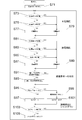
- FIG. 3 is a flowchart of the overall operation of the electric device system (charging system) 1.
- the control unit 13 switches the selection by the selection switch SW4 from the first resistor R1 to the second resistor R2, and sets the device-side D terminal 22 to the communication mode. Set (S3).
- the power supply circuit 51 is activated and the control unit 53 is activated (S5). If the battery pack 50 is in a chargeable state (YES in S7), the charging of the battery pack 50 by the charging device 10 is started and continued (S9).
- the control unit 13 switches the selection by the selection switch SW4 from the second resistor R2 to the first resistor R1 and the device side.
- the D terminal 22 is set to the connection detection mode (S13). After that, when a predetermined time has passed (YES in S15), the control unit 53 turns off the switching element SW3, stops the power supply circuit 51, and shuts down (S17). When the battery pack 50 is removed (NO in S19), the charging device 10 enters a standby state (S1).
- FIG. 4 is a flowchart of the operation of the charging device 10 in the standby mode.
- the control unit 13 sets the selection by the selection switch SW4 to the first resistance R1 and sets the device-side D terminal 22 to the connection detection mode (S31).
- V1 is a predetermined value that is lower than the power supply voltage VDD2 and higher than the voltage VD1 obtained by dividing the power supply voltage VDD2 by the first resistor R1 and the determination resistor R3.
- the battery pack 50 is connected to the charging device 10, the voltage of the device-side D terminal 22 becomes less than V1.
- FIG. 5 is a flowchart of the operation of the charging device 10 in the charging mode.
- the control unit 13 sets the selection by the selection switch SW4 as the second resistance R2 and sets the device-side D terminal 22 to the communication mode (S35).
- the control unit 13 transmits a battery state information request from the communication circuit 15 to the battery pack 50 (communication circuit 57) via the device side D terminal 22 and the battery side D terminal 62 (S37).
- the communication circuit 15 receives the battery status information from the battery pack 50 (communication circuit 57) via the device-side D terminal 22 and the battery-side D terminal 62 (YES in S39)
- the control unit 13 determines the status of the battery pack 50 (YES in S39).
- the charge current is within a predetermined value or range (YES in S43)
- the voltage of the battery pack 50 is less than the full charge voltage V2 (YES in S45)
- the device When the charge prohibition signal is not received from the battery pack 50 via the side LD terminal 23 and the battery side LD terminal 63 (YES in S47), charging of the battery pack 50 is started and continued (S49).
- the control unit 13 switches the selection by the selection switch SW4 to the first resistor R1 during charging and sets the device-side D terminal 22 to the connection detection mode (S51).
- the control unit 13 switches the selection by the selection switch SW4 to the second resistor R2 and returns to the communication mode (S35).
- the control unit 13 determines that the battery pack 50 has been removed from the charging device 10, and shifts to the standby mode (FIG. 4). If the battery state information is not received from the battery pack 50 for a predetermined time in step S39 (NO in S39, YES in S55), the control unit 13 determines that the state of the battery pack 50 has a problem (NO in S41).
- the voltage of the battery pack 50 is equal to or higher than the full charge voltage V2 (NO in S45), or the charge prohibition signal is received from the battery pack 50 (NO in S47), Charging of the battery pack 50 is stopped (S57), and the charging end mode (FIG. 6) is entered.
- FIG. 6 is a flowchart of the operation of the charging device 10 in the charging end mode.
- the control unit 13 sets the selection by the selection switch SW4 to the first resistor R1 and sets the device-side D terminal 22 to the connection detection mode (S59).
- the control unit 13 determines that the battery pack 50 has been removed from the charging device 10, and shifts to the standby mode (FIG. 4).
- FIG. 7 is a flowchart of the operation of the battery pack 50.
- the control unit 53 When activated, the control unit 53 outputs a signal to turn on the switching element SW3, and holds the power supply circuit 51 in a driven state (S71).
- the control unit 53 When the temperature of the battery cell group 55 is equal to or lower than the predetermined value (NO in S73) and the voltage of each battery cell is equal to or lower than the first predetermined value (NO in S75), the control unit 53 outputs the charge permission signal to the battery side LD terminal. It outputs to 63 (S77). In other words, the charge prohibition signal is not output from the battery side LD terminal 63.
- the control unit 53 charges the battery.
- a prohibition signal is output to the battery side LD terminal 63 (S79).
- the voltage of the battery cell being equal to or lower than the first predetermined value indicates a state in which the battery cell is not overcharged, overvoltaged or fully charged.
- the discharge permission signal is output to the battery side LD terminal 63 (S87). In other words, the discharge prohibition signal is not output to the LD terminal 63 on the battery side.
- the control unit 53 determines that the temperature of the battery cell group 55 exceeds a predetermined value (YES in S81), the voltage of at least one battery cell is less than the second predetermined value (YES in S83), or the discharge current is When it exceeds the predetermined value (YES in S85), the discharge inhibition signal is output to the battery side LD terminal 63 (S89).
- the voltage of the battery cell being equal to or higher than the second predetermined value indicates a state in which the battery cell is not over-discharged.
- the control unit 53 When the control unit 53 receives the battery status information request from the charging device 10 (communication circuit 15) via the device-side D terminal 22, the battery-side D terminal 62 and the communication circuit 57 (YES in S91), the charging is performed from the communication circuit 57.
- the battery status information is transmitted to the device 10 (communication circuit 15) via the battery side D terminal 62 and the device side D terminal 22 (S93).
- V3 is a predetermined value higher than the ground potential and smaller than the voltage VD1 obtained by dividing the power supply voltage VDD2 by the first resistor R1 and the discrimination resistor R3.
- the control unit 53 If the timer T1 does not exceed the predetermined value (NO in S103), the control unit 53 returns to step S73. When the timer T1 exceeds the predetermined value (YES in S103), that is, when the state in which the electric device body is not connected to the battery pack 50 continues beyond the predetermined value (predetermined time), the control unit 53 continues the switching element SW3. Is turned off and shut down (S105).
- the device-side D terminal 22 and the battery-side D terminal 62 are used as the activation terminal, the communication terminal, and the connection detection of the control unit 53 of the battery pack 50, the number of terminals can be reduced.
- the control unit 13 of the charging device 10 selects the first resistor R1 with the selection switch SW4 so that the switching element SW2 does not turn on the voltages of the device-side D terminal 22 and the battery-side D terminal 62. Since the voltage is set to the level, the connection of the battery pack 50 can be detected without activating the control unit 53 of the battery pack 50. Further, it is possible to obtain the type information of the battery pack 50 (rated voltage, number of connected cells, connection form of cells, etc.) by the determination resistor R3 without activating the control unit 53 of the battery pack 50. Therefore, unnecessary activation of the control unit 53 of the battery pack 50 can be suppressed, and an increase in power consumption of the battery pack 50 can be suppressed.
- the determination resistor R3 may be a thermistor provided near the battery cell group 55.
- the control unit 13 of the charging device 10 can detect the temperature (state) of the battery cell group 55 in the connection detection mode without activating the control unit 53 of the battery pack 50.
- the electric device body is not limited to the charging device 10 exemplified in the embodiment, and may be another type such as an electric tool. In this case, it is possible to provide a modified example in which the battery pack 50 is provided with a control unit for increasing added value such as for storage in addition to the control unit 53, and unnecessary activation of the control unit is suppressed to suppress an increase in power consumption. Is.
- SYMBOLS 1 Electrical equipment system (charging system), 10... Charging device, 11... Power supply circuit, 13... Control part (device side control part), 15... Communication circuit, 17... Switching circuit, 19... Switch, 21... Equipment side plus Terminal, 22... Device side D terminal, 23... Device side LD terminal, 24... Device side negative terminal, 50... Battery pack, 51... Power supply circuit, 53... Control unit (battery side control unit), 55... Battery cell group, 57... Communication circuit, 59... Connection detection circuit, 61... Battery side positive terminal (charge positive terminal), 62... Battery side D terminal, 63... Battery side LD terminal, 64... Battery side negative terminal, 67... Temperature detecting element , 69... Switching circuit
Landscapes
- Engineering & Computer Science (AREA)
- Manufacturing & Machinery (AREA)
- Chemical & Material Sciences (AREA)
- Chemical Kinetics & Catalysis (AREA)
- Electrochemistry (AREA)
- General Chemical & Material Sciences (AREA)
- Power Engineering (AREA)
- Charge And Discharge Circuits For Batteries Or The Like (AREA)
- Secondary Cells (AREA)
Abstract
端子数を削減しながら電池パックの電力消費の増大を抑制することの可能な電気機器、電池パック、及び充電システムを提供する。充電システム1は、充電装置10と、電池パック50と、を備える。充電装置10は、制御部13と、電池パック50の制御部53を起動する起動信号を電池パック50に送信するための機器側D端子22と、を備える。制御部13は、電池パック50の制御部53が起動していない状態で、電池パック50の情報、状態又は接続有無を示す信号を機器側D端子22から取得可能である。
Description
本発明は、制御部を有する電池パックと電池パックを接続可能な電気機器本体を備えた電気機器システムに関する。
下記特許文献1は、制御部(マイコン)を有する電池パックを充電装置により充電する充電システムを開示する。
特許文献1は電池パックの制御部が常に起動しているため、電池パックの電力を無駄に消費してしまう。また、電池パックの制御部を起動するための専用の端子を設けると端子数が多くなり電池パックや電気機器本体の大型化を招いてしまう。更に、端子数を節約するために、電池パックの制御部を起動するための端子に他の機能を持たせる場合、他の機能のために電池パックの制御部が不要に起動すると、電池パックの電力を無駄に消費する。
本発明はこうした状況を認識してなされたものであり、その目的は、電池パックの電力消費を抑制することの可能な電気機器システムを提供することにある。また他の目的は、端子数を抑えた電気機器システムを提供することにある。更に他の目的は、端子数を削減しながら電池パックの電力消費の増大を抑制することの可能な電気機器システムを提供することにある。
本発明のある態様は、電気機器システムである。この電気機器システムは、電池セル及び電池側制御部を備える電池パックと、機器側制御部を備え前記電池パックと接続可能な電気機器本体と、を有し、前記機器側制御部は、前記電池側制御部が起動していない状態で動作する第1モードと、前記電池側制御部が起動した状態で動作する第2モードと、を有する。
前記電池パックは電池側信号端子を備え、前記電気機器本体は前記電池側信号端子に接続可能な機器側信号端子を備え、前記機器側制御部は、前記電池側信号端子及び前記機器側信号端子を介して前記電池側制御部を起動する起動信号を前記電池パックに送信するよう構成し、前記機器側制御部は、前記電池側制御部が起動していない状態で、前記電池パックの情報、状態又は接続有無を示す信号を前記電池側信号端子及び前記機器側信号端子を介して取得可能であってもよい。
前記機器側制御部は、前記電池側信号端子及び前記機器側信号端子を使用して前記第1及び第2モードを切り替えてもよい。
前記第1モードは、前記電池パックが前記電気機器本体に接続されているか否かを検出する電池接続検出モードであり、前記第2モードは、前記機器側制御部と前記電池側制御部との間で通信を行う通信モードであってもよい。
前記機器側信号端子に接続され、前記第1モードと前記第2モードとを切替可能な切替回路を備え、前記電気機器本体は、前記切替回路が前記第2モードに切り替わると前記起動信号を出力するように制御してもよい。
前記切替回路は、一端が前記機器側信号端子に接続された互いに抵抗値の異なる第1及び第2抵抗と、前記第1及び第2抵抗のいずれかを選択して接続する選択回路と、を有し、前記機器側制御部は、前記切替回路による前記第1及び第2モードを切り替える際に、前記選択回路による前記第1及び第2抵抗の選択を切り替えてもよい。
前記機器側信号端子は、前記選択回路が前記第1抵抗を選択すると、前記電池側制御部が起動しない第1レベルの電圧となり、前記選択回路が前記第2抵抗を選択すると、前記電池側制御部が起動する第2レベルの電圧となってもよい。
前記電池パックは、一端が前記電池側信号端子に接続され、他端がグランド電位に接続された第3抵抗を有し、前記第1及び第2抵抗と前記第3抵抗の接続状態に応じて前記機器側信号端子の電圧が切り替わるようにしてもよい。
前記機器側制御部は、前記機器側信号端子の電圧が前記第2レベルの場合に、一時的に第1レベルの電圧に切り替えるようにしてもよい。
前記電気機器本体は、充電装置であって、前記機器側制御部は、前記第2モードで前記電池パックを充電し、前記電池パックの充電が完了すると、前記第1モードに移行してもよい。
前記機器側制御部は、前記第2モードで前記電池パックを充電中に、一時的に前記第1モードに切り替えるようにしてもよい。
前記電池側制御部は、前記電池セルから電力供給を受けて動作してもよい。
前記電池パックは、前記起動信号を受けて前記電池側制御部を起動させる起動回路を備えてもよい。
前記起動回路は、前記電池側制御部が起動されると、前記電池側制御部からの信号により前記電池側制御部の駆動状態を維持するようにしてもよい。
本発明のもう1つの態様は、電気機器システムである。この電気機器システムは、電池セル及び電池側制御部を有する電池パックと、前記電池パックを接続した充電装置と、を備え、前記電池パックは、前記電池側制御部を起動するための起動信号を前記充電装置から受信する電池側信号端子と、前記電池側信号端子に接続された、前記電池パックの情報、状態又は接続有無を示すための素子と、を有し、前記充電装置は、機器側制御部と、前記電池側信号端子と接続され、前記起動信号を前記電池パックに送信するための機器側信号端子と、を有し、前記機器側制御部は、前記電池側制御部が起動していない状態で、前記電池パックの情報、状態又は接続有無を示す信号を前記機器側信号端子から取得可能である。
なお、以上の構成要素の任意の組合せ、本発明の表現を方法などの間で変換したものもまた、本発明の態様として有効である。
本発明によれば、電池パックの電力消費を抑制することの可能な電気機器システムを提供することができる。また端子数を抑えた電気機器システムを提供することができる。また端子数を削減しながら電池パックの電力消費の増大を抑制することの可能な電気機器システムを提供することができる。
以下、図面を参照しながら本発明の好適な実施の形態を詳述する。なお、各図面に示される同一または同等の構成要素、部材、処理等には同一の符号を付し、適宜重複した説明は省略する。また、実施の形態は発明を限定するものではなく例示であり、実施の形態に記述されるすべての特徴やその組み合わせは必ずしも発明の本質的なものであるとは限らない。
図1は、本発明の実施の形態に係る電気機器システム(充電システム)1の回路ブロック図である。電気機器システム(充電システム)1は、電気機器本体となる充電装置10と、電池パック50と、を備える。充電装置10は、電池パック50との接続用に、機器側プラス端子21と、機器側信号端子としての機器側D端子22と、機器側報知用端子としての機器側LD端子23と、機器側マイナス端子24と、を有する。電池パック50は、電池側プラス端子(充電用プラス端子)61と、電池側信号端子としての電池側D端子62と、電池側報知用端子としての電池側LD端子63と、電池側マイナス端子64と、を有する。図示は省略したが、電池パック50は、放電用プラス端子を電池側プラス端子61とは別に有してもよいし共通の端子としてもよい。機器側プラス端子21と電池側プラス端子61が互いに接続される。機器側D端子22と電池側D端子62が互いに接続される。機器側LD端子23と電池側LD端子63が互いに接続される。機器側マイナス端子24と電池側マイナス端子64が互いに接続される。
充電装置10は、電源回路11と、制御部(機器側制御部)13と、通信回路15と、切替回路17と、スイッチ19と、を有する。電源回路11は、商用電源等の外部の交流電源5から供給される交流電圧を電池パック50の充電用の直流電圧に変換して機器側プラス端子21に出力すると共に、前記交流電圧を制御用の直流電圧VDD2に変換して充電装置10の各回路に供給する。制御部13は、充電装置10の全体の動作を制御する。通信回路15は、機器側D端子22に接続され、制御部13の制御に従い電池パック50の通信回路57との間で通信信号の送受信を行う。スイッチ19は、例えばリレーであり、制御部13の制御によって開閉される。充電装置10は、充電電流の経路に抵抗R5を有する。抵抗R5の両端の電圧により、制御部13が充電電流を検出する。制御部13は、機器側プラス端子21の電圧により、電池パック50の電圧を検出する。
切替回路17は、第1抵抗R1と、第2抵抗R2と、選択回路となる選択スイッチSW4と、を有する。第1抵抗R1及び第2抵抗R2の一端は、機器側D端子22に接続される。第1抵抗R1及び第2抵抗R2の他端は、選択スイッチSW4の一端に接続される。選択スイッチSW4の他端は、電源電圧VDD2が供給される電源ラインに接続される。第1抵抗R1の抵抗値は、第2抵抗R2の抵抗値よりも大きい。選択スイッチSW4は、制御部13の制御により、第1抵抗R1及び第2抵抗R2のいずれを電源ラインに接続するかを切り替える。選択スイッチSW4は、FET等のスイッチング素子で構成できる。
選択スイッチSW4が第1抵抗R1を電源ラインに接続すると、機器側D端子22の電圧は、電源電圧VDD2を第1抵抗R1と電池パック50の判別抵抗R3とで分圧した電圧レベルであって、グランド電位(0V)より高いが電池パック50の後述のスイッチング素子SW2をオンできない電圧レベル(図2のVD1)となる。選択スイッチSW4が第2抵抗R2を電源ラインに接続すると、機器側D端子22の電圧は、電源電圧VDD2を第2抵抗R2と電池パック50の判別抵抗R3とで分圧した電圧レベルであって、電池パック50のスイッチング素子SW2をオンできる電圧レベル(図2のVD2)となる。
制御部13は、第1モードとしての接続検出モードでは、第1抵抗R1を選択するように選択スイッチSW4を制御し、そのときの機器側D端子22の電圧VD1により、電池パック50が接続されたことを検出すると共に、電池パック50の種別(定格電圧や接続セル数、セルの接続形態等)に関する情報を取得する。制御部13は、第2モードとしての通信モードでは、第2抵抗R2を選択するように選択スイッチSW4を制御し、電池パック50のスイッチSW2をオンさせる。すると、後述のように、電池パック50の制御部53が起動する。その後、通信回路15は、電池パック50の通信回路57と通信する。
電池パック50は、電源回路51と、制御部(電池側制御部)53と、電池セル群55と、通信回路57と、接続検出回路59と、温度検出素子67と、切替回路69と、を有する。電源回路51は、電池セル群55の出力電圧を制御用の直流電圧VDD1に変換して電池パック50の各回路に供給する。充電装置10のスイッチ19がオンの場合、電源回路51は、充電装置10の電源回路11の出力電圧を制御用の直流電圧VDD1に変換して電池パック50の各回路に供給する。制御部53は、電池パック50の全体の動作を制御する。電池セル群55は、複数の電池セルを有する。通信回路57は、電池側D端子62に接続され、制御部53の制御に従い充電装置10の通信回路15との間で通信信号の送受信を行う。接続検出回路59は、電池側D端子62に接続され、充電装置10あるいは他の電気機器本体の接続検出の有無を検出する。電池パック50は、電池側D端子62とグランドとの間に判別抵抗R3を有する。判別抵抗R3は、電池パック50の情報及び接続有無を示すための素子の例示である。判別抵抗R3の抵抗値は、電池パック50の情報(定格電圧や接続セル数、セルの接続形態等)に応じた値である。
温度検出素子67は、例えばサーミスタであり、電池セル群55の近傍に配置され、電池セル群55の温度を検出する。なお、電池セルの中の1つのセル温度を検出してもよい。制御部53は、電池セル群55の各セルの電圧を監視する。また制御部53は、電池セル群55の温度を監視する。電池パック50は、放電電流の経路に抵抗R4を有する。抵抗R4の両端の電圧により、制御部53が放電電流を検出する。起動回路となる切替回路69は、FET等のスイッチング素子SW1~SW3と、抵抗R6と、を有する。切替回路69は、電池セル群55から電源回路51への電圧入力の有無を切り替える回路である。切替回路69を制御部53とは別にアナログ回路で構成することにより、安価な制御部53を使用することができる。電池側D端子62の電圧が、スイッチング素子SW2をオンできるレベルになると、スイッチング素子SW2がターンオンし、スイッチング素子SW1がターンオンし、電池セル群55から電源回路51に電圧が供給される。充電装置10において選択スイッチSW4が第2抵抗R2を選択すると、スイッチング素子SW2をオンできるレベルの電圧VD2(起動信号)が電池側D端子62からスイッチング素子SW2の制御端子(ゲート)に入力され、スイッチング素子SW2がターンオンする。電源回路51に電圧が供給されると、制御部53が起動する。制御部53は、スイッチング素子SW3をオンすることで、スイッチング素子SW2の状態にかかわらず、スイッチング素子SW1のオン状態を維持できる。
図2は、充電システム1の動作の一例を示すタイムチャートである。時刻t1以前は、充電装置10に電池パック50が接続されておらず、制御部13は待機モード(図4)かつ接続検出モードである。機器側D端子22は開放であるため、機器側D端子22の電圧は、選択スイッチSW4により選択されている第1抵抗R1によってプルアップされ、電源電圧VDD2である。電池側D端子62は開放であるため、電池側D端子62の電圧は、判別抵抗R3によってプルダウンされ、グランド電位である。電池パック50の電源回路51は、切替回路69により電池セル群55からの電圧供給遮断されており、オフである。
時刻t1において充電装置10に電池パック50が接続されると、制御部13は充電中モード(図5)となる。機器側D端子22及び電池側D端子62が互いに接続されるため、機器側D端子22及び電池側D端子62の電圧は、電源電圧VDD2を第1抵抗R1と判別抵抗R3で分圧した電圧VD1となる。機器側D端子22の電圧がVD1となったことにより、時刻t1から所定時間経過後の時刻t2において制御部13は充電装置10に電池パック50が接続されたことを検出し、接続検出モードから通信モードに移行し、選択スイッチSW4による選択を第1抵抗R1から第2抵抗R2に切り替える。すると、機器側D端子22及び電池側D端子62の電圧は、電源電圧VDD2を第2抵抗R2と判別抵抗R3で分圧した電圧VD2となる。これによりスイッチング素子SW2がターンオンし、電池パック50の電源回路51が起動する。
時刻t2以降、充電装置10の電源回路11から電池パック50の電池セル群55に充電電圧及び充電電流が供給され、電池パック50の充電が進められる。充電期間中、通信回路15、57による通信が行われ、また間欠的に制御部13は接続検出モードに移行する。通信では、電池セル群55の温度、各セルの電圧等が、制御部53から制御部13に送信される。制御部13が間欠的(一時的)に接続検出モードに移行するのは、充電装置10に電池パック50が接続されていることを充電中に簡易的かつ確実に検出するためである。制御部13は、通信により電池パック50が接続されていることを検出してもよい。ただしこの場合、例えば通信ができないときに、通信の異常なのか電池パック50が外されたのかを区別する必要があるため、簡易性と確実性の点で、間欠的に接続検出モードに移行するほうが有利である。
時刻t3において充電が完了すると、制御部13は充電終了モード(図6)かつ接続検出モードとなる。機器側D端子22及び電池側D端子62の電圧は、選択スイッチSW4の選択が第2抵抗R2から第1抵抗R1に切り替わることで、VD2からVD1に降下する。時刻t3から電源維持時間が経過した時刻t4において、制御部53はスイッチング素子SW3をターンオフし、電源回路51が停止する。その後の時刻t5において充電装置10から電池パック50が外されると、制御部13は待機モード(図4)に移行する。機器側D端子22は開放されるため、機器側D端子22の電圧は電源電圧VDD2となる。電池側D端子62は開放されるため、電池側D端子62の電圧はグランド電位となる。
図3は、電気機器システム(充電システム)1の全体動作のフローチャートである。充電装置10に電池パック50が接続されると(S1のYES)、制御部13は、選択スイッチSW4による選択を第1抵抗R1から第2抵抗R2に切り替え、機器側D端子22を通信モードに設定する(S3)。すると、電源回路51が起動し、制御部53が起動する(S5)。電池パック50が充電可能な状態であれば(S7のYES)、充電装置10による電池パック50の充電が開始、継続される(S9)。電池パック50が充電可能な状態でなければ(S7のNO)、充電が停止され(S11)、制御部13は、選択スイッチSW4による選択を第2抵抗R2から第1抵抗R1に切り替え、機器側D端子22を接続検出モードに設定する(S13)。その後、制御部53は、所定時間が経過すると(S15のYES)、スイッチング素子SW3をターンオフし、電源回路51を停止させ、シャットダウンする(S17)。充電装置10は、電池パック50が外されると(S19のNO)、待機状態となる(S1)。
図4は、充電装置10の待機モードの動作のフローチャートである。制御部13は、選択スイッチSW4による選択を第1抵抗R1とし、機器側D端子22を接続検出モードに設定する(S31)。制御部13は、機器側D端子22の電圧がV1未満になると(S33のYES)、充電中モードに移行する。V1は、電源電圧VDD2よりも低く、電源電圧VDD2を第1抵抗R1及び判別抵抗R3で分圧した電圧VD1よりも大きい所定値である。充電装置10に電池パック50が接続されると、機器側D端子22の電圧はV1未満となる。
図5は、充電装置10の充電中モードの動作のフローチャートである。制御部13は、選択スイッチSW4による選択を第2抵抗R2とし、機器側D端子22を通信モードに設定する(S35)。制御部13は、通信回路15から電池状態情報要求を機器側D端子22及び電池側D端子62を介して電池パック50(通信回路57)に送信する(S37)。制御部13は、通信回路15が機器側D端子22及び電池側D端子62を介して電池パック50(通信回路57)から電池状態情報を受信すると(S39のYES)、電池パック50の状態(温度等)に問題がなく(S41のYES)、充電電流が所定値あるいは所定範囲であり(S43のYES)、電池パック50の電圧が満充電電圧V2未満であり(S45のYES)、かつ機器側LD端子23及び電池側LD端子63を介して電池パック50から充電禁止信号を受信しない場合(S47のYES)、電池パック50の充電を開始、継続する(S49)。制御部13は、充電中に選択スイッチSW4による選択を第1抵抗R1に切り替え、機器側D端子22を接続検出モードに設定する(S51)。制御部13は、機器側D端子22の電圧がV1未満であれば(S52のYES)、選択スイッチSW4による選択を第2抵抗R2に切り替え、通信モードに戻る(S35)。制御部13は、機器側D端子22の電圧がV1以上の場合(S52のNO)、充電装置10から電池パック50が外されたと判断し、待機モード(図4)に移行する。制御部13は、ステップS39において電池パック50から電池状態情報を所定時間受信しない場合(S39のNO、S55のYES)、電池パック50の状態に問題がある場合(S41のNO)、充電電流が所定値あるいは所定範囲でない場合(S43のNO)、電池パック50の電圧が満充電電圧V2以上の場合(S45のNO)、あるいは電池パック50から充電禁止信号を受信した場合(S47のNO)、電池パック50の充電を停止し(S57)、充電終了モード(図6)に移行する。
図6は、充電装置10の充電終了モードの動作のフローチャートである。制御部13は、選択スイッチSW4による選択を第1抵抗R1とし、機器側D端子22を接続検出モードに設定する(S59)。制御部13は、機器側D端子22の電圧がV1以上になると(S61のNO)、充電装置10から電池パック50が外されたと判断し、待機モード(図4)に移行する。
図7は、電池パック50の動作のフローチャートである。制御部53は、起動すると、信号を出力してスイッチング素子SW3をオンし、電源回路51を駆動状態に保持する(S71)。制御部53は、電池セル群55の温度が所定値以下であり(S73のNO)、各電池セルの電圧が第1所定値以下の場合(S75のNO)、充電許可信号を電池側LD端子63に出力する(S77)。言い換えると充電禁止信号を電池側LD端子63出力しない。制御部53は、電池セル群55の温度が所定値を超えている場合(S73のYES)、又は少なくとも1つの電池セルの電圧が第1所定値を超えている場合(S75のYES)、充電禁止信号を電池側LD端子63に出力する(S79)。なお、電池セルの電圧が第1所定値以下とは電池セルが過充電又は過電圧又は満充電になっていない状態を示している。
制御部53は、電池セル群55の温度が所定値以下であり(S81のNO)、各電池セルの電圧が第2所定値以上であり(S83のNO)、放電電流が所定値以下の場合(S85のNO)、放電許可信号を電池側LD端子63に出力する(S87)。言い換えると放電禁止信号を電池側LD端子63に出力しない。制御部53は、電池セル群55の温度が所定値を超えている場合(S81のYES)、少なくとも1つの電池セルの電圧が第2所定値未満の場合(S83のYES)、又は放電電流が所定値を超えた場合(S85のYES)、放電禁止信号を電池側LD端子63に出力する(S89)。なお、電池セルの電圧が第2所定値以上とは電池セルが過放電になっていない状態を示している。
制御部53は、充電装置10(通信回路15)から機器側D端子22、電池側D端子62及び通信回路57を介して電池状態情報要求を受信すると(S91のYES)、通信回路57から充電装置10(通信回路15)に対して電池側D端子62及び機器側D端子22を介して電池状態情報を送信する(S93)。
制御部53は、電池側D端子62の電圧が、機器本体の接続があることを示すV3未満場合(S95のYES)、タイマT1をインクリメントする(S97)。制御部53は、電池側D端子62の電圧がV3以上の場合(S95のNO)、スイッチング素子SW3をオンにして電源回路51を駆動状態に保持し(S99)、タイマT1をクリアする(S101)。V3は、グランド電位よりも高く、電源電圧VDD2を第1抵抗R1及び判別抵抗R3で分圧した電圧VD1よりも小さい所定値である。電池パック50を充電装置10に接続すると、電池側D端子62の電圧はV3以上となる。具体的にはVD1となる。制御部53は、タイマT1が所定値を超えていなければ(S103のNO)、ステップS73に戻る。制御部53は、タイマT1が所定値を超えると(S103のYES)、すなわち、電池パック50に電気機器本体が接続されていない状態が所定値(所定時間)を超えて継続すると、スイッチング素子SW3をターンオフし、シャットダウンする(S105)。
本実施の形態によれば、下記の効果を奏することができる。
(1) 機器側D端子22及び電池側D端子62を、電池パック50の制御部53の起動用端子、通信端子、及び接続検出用として使用するため、端子数を削減できる。
(2) 充電装置10の制御部13は、接続検出モードでは選択スイッチSW4により第1抵抗R1を選択することで、機器側D端子22及び電池側D端子62の電圧をスイッチング素子SW2がオンしないレベルの電圧とするので、電池パック50の制御部53を起動せずに電池パック50の接続検出が可能となる。また、電池パック50の制御部53を起動せずに判別抵抗R3によって電池パック50の種別(定格電圧や接続セル数、セルの接続形態等)情報の取得が可能となる。よって、電池パック50の制御部53の不要な起動を抑制でき、電池パック50の電力消費の増大を抑制できる。
以上、実施の形態を例に本発明を説明したが、実施の形態の各構成要素や各処理プロセスには請求項に記載の範囲で種々の変形が可能であることは当業者に理解されるところである。以下、変形例について触れる。
判別抵抗R3は、電池セル群55の近傍に設けられたサーミスタであってもよい。この場合、充電装置10の制御部13は、接続検出モードにおいて、電池パック50の制御部53を起動せずに、電池セル群55の温度(状態)を検出できる。電気機器本体は、実施の形態で例示した充電装置10に限定されず、電動工具等の他の種類のものであってもよい。この場合、電池パック50に、制御部53とは別に記憶用等の付加価値を高める制御部を設け、当該制御部の不要な起動を抑制して消費電力の増大を抑制するという変形例が可能である。
1…電気機器システム(充電システム)、10…充電装置、11…電源回路、13…制御部(機器側制御部)、15…通信回路、17…切替回路、19…スイッチ、21…機器側プラス端子、22…機器側D端子、23…機器側LD端子、24…機器側マイナス端子、50…電池パック、51…電源回路、53…制御部(電池側制御部)、55…電池セル群、57…通信回路、59…接続検出回路、61…電池側プラス端子(充電用プラス端子)、62…電池側D端子、63…電池側LD端子、64…電池側マイナス端子、67…温度検出素子、69…切替回路
Claims (15)
- 電池セル及び電池側制御部を備える電池パックと、機器側制御部を備え前記電池パックと接続可能な電気機器本体と、を有する電気機器システムであって、
前記機器側制御部は、前記電池側制御部が起動していない状態で動作する第1モードと、前記電池側制御部が起動した状態で動作する第2モードと、を有する、電気機器システム。 - 前記電池パックは電池側信号端子を備え、
前記電気機器本体は前記電池側信号端子に接続可能な機器側信号端子を備え、
前記機器側制御部は、前記電池側信号端子及び前記機器側信号端子を介して前記電池側制御部を起動する起動信号を前記電池パックに送信するよう構成し、
前記機器側制御部は、前記電池側制御部が起動していない状態で、前記電池パックの情報、状態又は接続有無を示す信号を前記電池側信号端子及び前記機器側信号端子を介して取得可能である、請求項1に記載の電気機器システム。 - 前記機器側制御部は、前記電池側信号端子及び前記機器側信号端子を使用して前記第1及び第2モードを切り替える、請求項1又は2に記載の電気機器システム。
- 前記第1モードは、前記電池パックが前記電気機器本体に接続されているか否かを検出する電池接続検出モードであり、
前記第2モードは、前記機器側制御部と前記電池側制御部との間で通信を行う通信モードである、請求項1から3のいずれか一項に記載の電気機器システム。 - 前記機器側信号端子に接続され、前記第1モードと前記第2モードとを切替可能な切替回路を備え、
前記電気機器本体は、前記切替回路が前記第2モードに切り替わると前記起動信号を出力するように制御する、請求項1から4のいずれか一項に記載の電気機器システム。 - 前記切替回路は、一端が前記機器側信号端子に接続された互いに抵抗値の異なる第1及び第2抵抗と、前記第1及び第2抵抗のいずれかを選択して接続する選択回路と、を有し、
前記機器側制御部は、前記切替回路による前記第1及び第2モードを切り替える際に、前記選択回路による前記第1及び第2抵抗の選択を切り替える、請求項5に記載の電気機器システム。 - 前記機器側信号端子は、前記選択回路が前記第1抵抗を選択すると、前記電池側制御部が起動しない第1レベルの電圧となり、前記選択回路が前記第2抵抗を選択すると、前記電池側制御部が起動する第2レベルの電圧となる、請求項6に記載の電気機器システム。
- 前記電池パックは、一端が前記電池側信号端子に接続され、他端がグランド電位に接続された第3抵抗を有し、
前記第1及び第2抵抗と前記第3抵抗の接続状態に応じて前記機器側信号端子の電圧が切り替わる、請求項7に記載の電気機器システム。 - 前記機器側制御部は、前記機器側信号端子の電圧が前記第2レベルの場合に、一時的に第1レベルの電圧に切り替える、請求項7又は8に記載の電気機器システム。
- 前記電気機器本体は充電装置であって、
前記機器側制御部は、前記第2モードで前記電池パックを充電し、前記電池パックの充電が完了すると、前記第1モードに移行する、請求項1から8のいずれか一項に記載の電気機器システム。 - 前記機器側制御部は、前記第2モードで前記電池パックを充電中に、一時的に前記第1モードに切り替える、請求項1から10のいずれか一項に記載の電気機器システム。
- 前記電池側制御部は、前記電池セルから電力供給を受けて動作する、請求項1から11のいずれか一項に記載の電気機器システム。
- 前記電池パックは、前記起動信号を受けて前記電池側制御部を起動させる起動回路を備える、請求項1から12のいずれか一項に記載の電気機器システム。
- 前記起動回路は、前記電池側制御部が起動されると、前記電池側制御部からの信号により前記電池側制御部の駆動状態を維持する、請求項13に記載の電気機器システム。
- 電池セル及び電池側制御部を有する電池パックと、
前記電池パックを接続した充電装置と、を備えた電気機器システムであって、
前記電池パックは、
前記電池側制御部を起動するための起動信号を前記充電装置から受信する電池側信号端子と、
前記電池側信号端子に接続され、前記電池パックの情報、状態又は接続有無を示すための素子と、を有し、
前記充電装置は、
機器側制御部と、
前記電池側信号端子と接続され、前記起動信号を前記電池パックに送信するための機器側信号端子と、を有し、
前記機器側制御部は、前記電池側制御部が起動していない状態で、前記電池パックの情報、状態又は接続有無を示す信号を前記機器側信号端子から取得可能である、充電システム。
Priority Applications (1)
| Application Number | Priority Date | Filing Date | Title |
|---|---|---|---|
| JP2020558194A JP7272371B2 (ja) | 2018-11-30 | 2019-10-25 | 電気機器システム |
Applications Claiming Priority (2)
| Application Number | Priority Date | Filing Date | Title |
|---|---|---|---|
| JP2018-224429 | 2018-11-30 | ||
| JP2018224429 | 2018-11-30 |
Publications (1)
| Publication Number | Publication Date |
|---|---|
| WO2020110541A1 true WO2020110541A1 (ja) | 2020-06-04 |
Family
ID=70853766
Family Applications (1)
| Application Number | Title | Priority Date | Filing Date |
|---|---|---|---|
| PCT/JP2019/041961 Ceased WO2020110541A1 (ja) | 2018-11-30 | 2019-10-25 | 電気機器システム |
Country Status (2)
| Country | Link |
|---|---|
| JP (1) | JP7272371B2 (ja) |
| WO (1) | WO2020110541A1 (ja) |
Citations (2)
| Publication number | Priority date | Publication date | Assignee | Title |
|---|---|---|---|---|
| JP2012130174A (ja) * | 2010-12-16 | 2012-07-05 | Panasonic Corp | 充電システム |
| JP2017216861A (ja) * | 2016-05-30 | 2017-12-07 | 日立工機株式会社 | 電池パック、充電装置、及び電動工具 |
Family Cites Families (3)
| Publication number | Priority date | Publication date | Assignee | Title |
|---|---|---|---|---|
| JP2012143020A (ja) * | 2010-12-28 | 2012-07-26 | Panasonic Corp | 充電システム |
| JP2015196196A (ja) * | 2014-03-31 | 2015-11-09 | 日立工機株式会社 | 電動工具 |
| JP6338076B2 (ja) * | 2015-02-10 | 2018-06-06 | 日立工機株式会社 | 充電装置 |
-
2019
- 2019-10-25 JP JP2020558194A patent/JP7272371B2/ja active Active
- 2019-10-25 WO PCT/JP2019/041961 patent/WO2020110541A1/ja not_active Ceased
Patent Citations (2)
| Publication number | Priority date | Publication date | Assignee | Title |
|---|---|---|---|---|
| JP2012130174A (ja) * | 2010-12-16 | 2012-07-05 | Panasonic Corp | 充電システム |
| JP2017216861A (ja) * | 2016-05-30 | 2017-12-07 | 日立工機株式会社 | 電池パック、充電装置、及び電動工具 |
Also Published As
| Publication number | Publication date |
|---|---|
| JPWO2020110541A1 (ja) | 2021-10-14 |
| JP7272371B2 (ja) | 2023-05-12 |
Similar Documents
| Publication | Publication Date | Title |
|---|---|---|
| CN212485397U (zh) | 电池组和电气组合 | |
| EP1124300B1 (en) | Battery charging apparatus, battery pack and method for charging secondary battery | |
| US11637433B2 (en) | Battery pack and electrical apparatus | |
| US10199844B2 (en) | Power-supplying device | |
| CN109698532B (zh) | 充电控制装置、蓄电池组以及充电器 | |
| JP7336264B2 (ja) | バッテリパック | |
| EP4266539A1 (en) | Power supply device | |
| KR20160023172A (ko) | 전력 소모를 최소화한 과충전 방지 장치 | |
| US5397974A (en) | Rechargeable battery overdischarge prevention circuit | |
| JP2009178014A (ja) | 充電装置 | |
| JP2001283934A (ja) | 電池パック識別装置及び電池パック | |
| JP7272371B2 (ja) | 電気機器システム | |
| US20050110462A1 (en) | Power charger and rechargeable battery system | |
| WO2002087055A1 (en) | Electronic apparatus having charging function | |
| JP7192877B2 (ja) | 電気機器システム | |
| TWI868234B (zh) | 電池充電方法、電池充電裝置及電池充電系統 | |
| KR102584312B1 (ko) | e-모빌리티의 배터리 자동 전환 장치 및 이를 포함한 시스템 | |
| JP2020131877A (ja) | 電池監視装置 | |
| JP5288976B2 (ja) | ハイブリッドバッテリの充電制御方法 | |
| JP4189987B2 (ja) | 電池パック及び該電池パックを電源とする外部ホスト機器システム | |
| JP2022544466A (ja) | 非常電源供給装置 | |
| JP2022047802A (ja) | 電子機器、電池パック、制御方法およびプログラム | |
| JPH08106922A (ja) | 充電装置 | |
| JPH0799730A (ja) | 充放電装置 | |
| JP2002354694A (ja) | 充電機能付き電子機器 |
Legal Events
| Date | Code | Title | Description |
|---|---|---|---|
| 121 | Ep: the epo has been informed by wipo that ep was designated in this application |
Ref document number: 19890221 Country of ref document: EP Kind code of ref document: A1 |
|
| ENP | Entry into the national phase |
Ref document number: 2020558194 Country of ref document: JP Kind code of ref document: A |
|
| NENP | Non-entry into the national phase |
Ref country code: DE |
|
| 122 | Ep: pct application non-entry in european phase |
Ref document number: 19890221 Country of ref document: EP Kind code of ref document: A1 |