WO2020110321A1 - 防音放熱材、防音放熱材付き機器及び防音放熱材の製造方法 - Google Patents
防音放熱材、防音放熱材付き機器及び防音放熱材の製造方法 Download PDFInfo
- Publication number
- WO2020110321A1 WO2020110321A1 PCT/JP2018/044325 JP2018044325W WO2020110321A1 WO 2020110321 A1 WO2020110321 A1 WO 2020110321A1 JP 2018044325 W JP2018044325 W JP 2018044325W WO 2020110321 A1 WO2020110321 A1 WO 2020110321A1
- Authority
- WO
- WIPO (PCT)
- Prior art keywords
- heat
- soundproof
- sound
- dissipating
- heat dissipation
- Prior art date
- Legal status (The legal status is an assumption and is not a legal conclusion. Google has not performed a legal analysis and makes no representation as to the accuracy of the status listed.)
- Ceased
Links
Images


Classifications
-
- G—PHYSICS
- G10—MUSICAL INSTRUMENTS; ACOUSTICS
- G10K—SOUND-PRODUCING DEVICES; METHODS OR DEVICES FOR PROTECTING AGAINST, OR FOR DAMPING, NOISE OR OTHER ACOUSTIC WAVES IN GENERAL; ACOUSTICS NOT OTHERWISE PROVIDED FOR
- G10K11/00—Methods or devices for transmitting, conducting or directing sound in general; Methods or devices for protecting against, or for damping, noise or other acoustic waves in general
- G10K11/16—Methods or devices for protecting against, or for damping, noise or other acoustic waves in general
-
- G—PHYSICS
- G10—MUSICAL INSTRUMENTS; ACOUSTICS
- G10K—SOUND-PRODUCING DEVICES; METHODS OR DEVICES FOR PROTECTING AGAINST, OR FOR DAMPING, NOISE OR OTHER ACOUSTIC WAVES IN GENERAL; ACOUSTICS NOT OTHERWISE PROVIDED FOR
- G10K11/00—Methods or devices for transmitting, conducting or directing sound in general; Methods or devices for protecting against, or for damping, noise or other acoustic waves in general
- G10K11/16—Methods or devices for protecting against, or for damping, noise or other acoustic waves in general
- G10K11/162—Selection of materials
Definitions
- the present invention relates to a soundproof heat dissipation material, a device with the soundproof heat dissipation material, and a method for manufacturing the soundproof heat dissipation material.
- the soundproofing member include a member including a urethane foam layer, an airgel layer, a cotton-like mixed long glass fiber, a fiber layer made of at least one of an organic long fiber and an inorganic long fiber.
- the soundproofing member has a heat insulating property, heat dissipation is hindered when the soundproofing member is arranged at the noise source.
- a soundproof member having excellent soundproofing properties and heat dissipation properties a phenolic hard foam having an open cell structure is pressed and filled into cells of an aluminum honeycomb material to form a core layer material, and a sound is formed on one surface of the core layer material.
- a honeycomb panel body has been proposed in which an air-permeable surface material that allows heat to pass through is attached to another surface by a plate material that reflects sound but allows heat to pass through with an adhesive (for example, see Patent Document 1). ..
- the present disclosure has been made in view of the above problems, and a sound-insulating heat-dissipating material having excellent heat-dissipating and sound-insulating properties, a device with the sound-insulating heat-dissipating material including the same, and a sound-insulating heat-dissipating material capable of following the shapes of devices that emit noise and heat. It is an object of the present invention to provide a method for manufacturing a soundproof and heat radiating material capable of manufacturing the above.
- a sound-insulating and heat-dissipating material comprising a soundproof material and metal fibers arranged inside the soundproof material, wherein a part of the metal fibers is exposed or protruded from at least two surfaces of the soundproof material.
- ⁇ 4> The soundproof and heat radiating material according to any one of ⁇ 1> to ⁇ 3>, wherein the metal fiber has a contact point where the metal fibers are bonded to each other.
- ⁇ 5> The soundproof heat-dissipating material according to any one of ⁇ 1> to ⁇ 4>, which is a resin body.
- ⁇ 6> The sound-insulating and heat-dissipating material according to any one of ⁇ 1> to ⁇ 4>, which is a resin foam.
- ⁇ 7> The sound-insulating heat-dissipating material according to ⁇ 6>, wherein the resin foam is a urethane resin foam.
- ⁇ 8> The sound-insulating heat-dissipating material according to any one of ⁇ 1> to ⁇ 7>, in which the proportion of the metal fibers in the sound-insulating heat-dissipating material is 1% by volume to 30% by volume.
- ⁇ 9> The soundproof heat dissipation material according to any one of ⁇ 1> to ⁇ 8>, which is installed in a device that emits noise and heat by being sandwiched between a cover member and a device that emits noise and heat.
- a device with noise and heat dissipation material comprising: a device that emits noise and heat and that is arranged on at least one surface side of the at least two surfaces.
- placing metal fibers in the mold A step of injecting a resin into the mold in which the metal fibers are arranged to produce a soundproof material that is a resin body, and a method for producing a soundproof heat dissipation material.
- a sound-insulating heat-dissipating material having excellent heat-dissipating properties and sound-insulating properties a device having the sound-insulating heat-dissipating material including the same, and a sound-insulating heat-dissipating material capable of manufacturing the sound-dissipating heat-dissipating material capable of following the shapes of devices emitting noise and heat are manufactured.
- a method can be provided.
- the present invention is not limited to the following embodiments.
- the constituent elements including element steps and the like
- the term “process” includes not only a process independent of other processes but also the process even if the process is not clearly distinguishable from the other processes as long as the purpose of the process is achieved. ..
- the numerical range indicated by using "to” includes the numerical values before and after "to" as the minimum value and the maximum value, respectively.
- the upper limit value or the lower limit value described in one numerical range may be replaced with the upper limit value or the lower limit value of another stepwise described numerical range. ..
- the configuration of the embodiment is not limited to the configuration illustrated in the drawings.
- the sizes of the members in each drawing are conceptual, and the relative size relationship between the members is not limited to this.
- “soundproof” includes “sound insulation” and “sound absorption”
- “soundproof heat dissipation material” may be appropriately read as “sound insulation heat dissipation material” or “sound absorption heat dissipation material”.
- the soundproof heat-dissipating material of the present disclosure includes a soundproofing material and metal fibers disposed inside the soundproofing material, and a part of the metal fiber is exposed or protrudes from at least two surfaces of the soundproofing material.
- the structure in which a part of the metal fiber is exposed or protrudes may include both a structure in which a part of the metal fiber is exposed and a structure in which another part of the metal fiber is protruded.
- the soundproof heat-dissipating material of the present disclosure is arranged, for example, so as to come into contact with a compressor or the like, which is a device that emits noise and heat, directly or through another member, suppresses noise from this device, and suppresses heat generated. It is used to radiate heat to the outside.
- At least one of the at least two surfaces is a surface on the device side that emits noise and heat, and at least one surface other than the surface on the device side is a heat dissipation side. It is a surface, and the heat generated on the device side may be radiated from the heat radiation side.
- “at least two surfaces” may be two surfaces, or may be one surface and the other surface that face each other in terms of excellent heat dissipation of the soundproof heat dissipation material.
- “one surface” refers to one of the main surfaces orthogonal to the thickness direction of the soundproof heat dissipation material
- “the other surface” refers to the surface opposite to the one surface. It is preferable to point.
- the soundproof heat dissipation material of the present disclosure includes a soundproof material.
- the soundproofing material is not particularly limited as long as it has a soundproofing effect, a soundproofing effect such as a sound absorbing effect, and may be foamed urethane resin, foamed phenol resin, foamed polystyrene resin, foamed polypropylene resin, foamed polyethylene resin, foamed synthetic rubber, or the like.
- a resin foam obtained by foaming a foamed resin or the like can be mentioned.
- the soundproof material may be a resin body formed by molding a non-foaming resin such as urethane resin, phenol resin, polystyrene resin, polypropylene resin, polyethylene resin, or synthetic rubber.
- a non-foaming resin such as urethane resin, phenol resin, polystyrene resin, polypropylene resin, polyethylene resin, or synthetic rubber.
- a urethane resin foam obtained by foaming a urethane foam resin and a resin body obtained by molding a urethane resin are preferable.
- a foaming agent such as water, an azo compound such as azodicarbonamide, or azobisisobutyronitrile may be used.
- the width and the thickness of the soundproof material are not particularly limited, and can be adjusted according to the application of the soundproof heat dissipation material.
- the thickness of the soundproof material may be 1 mm to 50 mm, 3 mm to 30 mm, or 5 mm to 20 mm.
- the ratio of the soundproofing material to the soundproofing and heat-dissipating material of the present disclosure is preferably 70% by volume or more from the viewpoint of soundproofing, and when the soundproofing and heat-dissipating material is manufactured, since the amount of the metal fibers is too large, the foamed resin is filled. From the viewpoint of suppressing the deterioration of the properties, it is preferably 80% by volume or more, and more preferably 90% by volume or more. From the viewpoint of heat dissipation, the ratio of the soundproofing material to the soundproofing and heat dissipating material of the present disclosure is preferably 99% by volume or less, and more preferably 95% by volume or less.
- the ratio of the soundproof material includes the bubble portion.
- the ratio of the soundproofing material is, for example, from the volume of the soundproofing and heat radiating material and the volume of the metal fiber obtained by removing the soundproofing material, such as a resin foam, from the soundproofing and heat radiating material by processing such as heating and melting. It can be calculated.
- the metal fiber preferably contains at least one metal selected from the group consisting of aluminum, iron, copper and alloys containing these (for example, stainless steel). It is more preferable that the linear heat dissipation member contains at least one metal selected from the group consisting of aluminum, copper, and alloys containing these, because it has excellent heat conductivity.
- the metal fiber may be, for example, a fiber in which tin or the like is surface-treated by plating or the like.
- the metal fibers may be web-shaped or felt-shaped.
- metal fibers produced by a melt spinning method, a cutting method, a drawing method, or the like may be processed into a web shape or a felt shape.
- the metal fiber may have a contact point where the metal fibers are bonded to each other by sintering or the like.
- the wire diameter of the metal fiber is preferably 0.01 mm or more, more preferably 0.05 mm or more, and further preferably 0.1 mm or more, from the viewpoint of excellent heat conductivity.
- the wire diameter of the metal fiber is preferably 0.5 mm or less, more preferably 0.3 mm or less, and further preferably 0.2 mm or less from the viewpoint of easy production of the metal fiber. preferable.
- the wire diameter of the metal fiber changes depending on the position, it is preferable to satisfy the above-mentioned numerical range of the wire diameter of the metal fiber in at least one place, and to satisfy 0.01 mm or more at the position where the wire diameter is the smallest, It is preferable to satisfy 0.5 mm or less at the position where the diameter is the largest.
- the proportion of metal fibers in the soundproof and heat dissipation material of the present disclosure is preferably 1% by volume or more, more preferably 2% by volume or more, and further preferably 3% by volume or more. preferable.
- the ratio of the metal fibers in the soundproof and heat dissipating material of the present disclosure is preferably 30% by volume or less from the viewpoint of soundproofing, and the filling property of the foamed resin between the metal fibers when manufacturing the soundproof and heat dissipating material. From the point of, it is preferably 10% by volume or less.
- the soundproof heat dissipation material of the present disclosure may be installed in a device that emits noise and heat by being sandwiched between a cover member and a device that emits noise and heat.
- the cover member include a metal cover and a resin cover having high heat conductivity.
- the metal cover aluminum, magnesium, alloys thereof, stainless steel, or the like can be used.
- the sound radiating material of the present invention is not limited to the following specific examples, and the configurations of these specific examples may be combined if necessary. For example, it suffices that a part of the metal fiber is exposed or protrudes from at least two surfaces of the soundproof material, and the present invention is not limited to a configuration in which a part of the metal fiber is exposed or protrudes from the two opposite surfaces of the soundproof material. ..
- FIG. 1 shows a schematic cross-sectional view of a specific example 1 of the soundproof heat dissipation material.
- the soundproof heat dissipation material 100 includes a soundproof material 1 and a metal fiber 2, and a part of the metal fiber 2 is exposed from two opposing surfaces of the soundproof material 1. Thereby, the soundproof heat dissipation material 100 is excellent in heat dissipation and soundproofing.
- FIG. 2 shows a schematic cross-sectional view of a specific example 2 of the soundproof heat dissipation material.
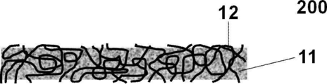
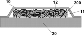
- the sound-insulating heat-dissipating material 200 includes a sound-insulating material 11 and a metal fiber 12, and a part of the metal fiber 12 projects from two opposing surfaces of the sound-insulating material 11.
- the sound-insulating heat-dissipating material 200 has an increased heat transfer area, is more likely to receive heat from a device that emits noise and heat, and is more likely to dissipate heat to the heat-dissipating surface.
- a method of protruding a part of the metal fiber 12 inside the soundproof material 11 may be mentioned, and more specifically, the soundproof material 11 may be removed by polishing two opposing surfaces of the soundproof material 11.
- paraffin wax which is a material that easily elutes in a solvent
- the metal fiber may be filled with a material that serves as a soundproofing material to form a molded body, and then the paraffin wax or the like may be removed by elution with a solvent or the like.
- FIG. 3 shows a schematic diagram of a specific example 3 of the soundproof heat dissipation material.
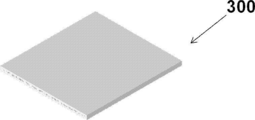
- the sound-insulating heat-dissipating material 300 has a flat plate shape, and metal fibers (not shown) are exposed or project from two opposing main surfaces.
- FIG. 4 shows a schematic view of a specific example 4 of the soundproof heat dissipation material.
- the soundproof heat dissipation member 400 shown in FIG. 4 is similar to the soundproof heat dissipation member 300 except that it is curved.
- the sound-insulating heat-dissipating material having such a shape can be obtained, for example, by bending the sound-insulating heat-dissipating material of Example 3, or can be manufactured by the sound-dissipating heat-dissipating material manufacturing method of the present disclosure described later.
- FIG. 5 shows a schematic view of a specific example 5 of the soundproof heat dissipation material.
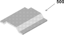
- the sound-insulating heat-dissipating material 500 shown in FIG. 5 is partially shaped like a trapezoid.
- the sound-insulating heat-dissipating material having such a shape can be manufactured, for example, by the sound-insulating heat-dissipating material manufacturing method of the present disclosure described later.
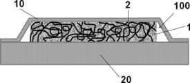
- the soundproof heat dissipation material 100 is installed in the noise source 20 by being sandwiched between the metal cover 10 such as a stainless steel cover and the noise source 20 (equipment that emits noise and heat). Good. Since the metal fiber 2 contacts the metal cover 10 and the noise source 20, heat is easily transferred from the noise source 20 to the metal cover 10.
- the metal cover 10 and at least one of the noise source 20 and the soundproof heat dissipation material 100 may be in contact with each other or may be welded to each other.
- the metal cover 10 and at least one of the noise source 20 and the soundproof heat dissipation material 100 may be in contact with each other via a member having a high heat dissipation property or may be welded.
- the soundproof heat dissipation material 200 is installed in the noise source 20 by being sandwiched between the metal cover 10 such as a stainless steel cover and the noise source 20 (equipment that emits noise and heat). Good.
- a part of the metal fiber 12 is projected from the two opposite surfaces of the soundproof material 11. Since the metal fiber 12 has flexibility, the metal fiber 12 protruding to the irregularities of the metal cover 10 and the noise source 20 follows. There is. As a result, the heat transfer area is increased, so that the noise source 20 can more easily receive heat and the metal cover 10 can more easily radiate heat.
- the metal cover 10 and at least one of the noise source 20 and the metal fiber 12 may be in contact with each other or may be welded to each other.
- the metal cover 10 and at least one of the noise source 20 and the metal fiber 12 may be in contact with each other via a member having a high heat dissipation property, or may be welded to each other.
- a device with a soundproof and heat dissipating material according to the present disclosure includes the soundproof and heat dissipating material according to the present disclosure described above, and a device that emits noise and heat and is disposed on at least one surface side of at least two surfaces.
- the soundproof heat dissipation material and the device that emits noise and heat may be in direct contact with each other on at least one surface side, and may be in contact with each other via a member having a high heat dissipation property. You may have. Further, the sound-insulating heat-dissipating material may be in direct contact with the cover member disposed on at least one surface side other than the device side described above, or may be in contact with the cover member via a member having high heat dissipation. ..
- a method 1 for manufacturing a soundproof and heat dissipating material according to the present disclosure includes a step of disposing metal fibers in a mold, A step of injecting a resin into the mold in which the metal fibers are arranged to produce a soundproof material that is a resin body.
- the sound-insulating heat-dissipating material of the present disclosure described above in which the sound-insulating material is a resin body can be manufactured.
- a mold corresponding to the shape of a device that emits noise and heat is prepared, metal fibers having excellent flexibility are formed in the device that emits noise and heat, and then the resin is molded in the mold.
- a method 2 for manufacturing a soundproofing/heat-dissipating material according to the present disclosure includes a step of disposing metal fibers in a mold, a step of injecting a foam resin into the mold in which the metal fibers are arranged, and a step of injecting the foam resin into the mold. Foaming to produce a soundproof material that is a resin foam.
- the sound-insulating heat-dissipating material of the present disclosure in which the sound-insulating material is a foamed resin body, can be manufactured.
- a mold corresponding to the shape of a device that emits noise and heat is prepared, metal fibers having excellent flexibility are shaped in the device that emits noise and heat, and then a foamed resin is molded.
- a foamed resin is molded.
- the method for manufacturing the soundproof and heat dissipating material of the present disclosure is not limited to the above-described manufacturing methods 1 and 2 of the soundproof and heat dissipating material of the present disclosure.
- Example 1 (Preparation of soundproof heat dissipation material)
- iron, aluminum, copper and stainless fibers having the wire diameters shown in Table 1 were used as the metal fibers.
- a metal fiber was placed in a mold having an inner shape of width 50 mm ⁇ length 50 mm ⁇ height 10 mm, urethane resin was injected into the mold, and heated to foam to produce a soundproof heat dissipation material.
- Table 1 shows the proportion (volume %) of the soundproof material in the soundproof heat dissipation material.
- the heat transfer coefficients of the soundproof heat dissipation materials of Examples 1 to 21 and the sound insulation material of Comparative Example 1 were determined by the thermal circuit network method.
- the ratio of the soundproof material is ⁇ (volume %)
- the thermal conductivity of the metal fiber is ⁇ m (W ⁇ m ⁇ 1 ⁇ K ⁇ 1 )
- the thermal conductivity of the soundproof material is ⁇ n (W ⁇ m ⁇ 1 ⁇ K ⁇ ). 1
- the thickness of the soundproofing material was d(m)
- the thermal conductivity was calculated from the following equation (1).
- Heat transfer coefficient ((100 ⁇ )/100 ⁇ m ⁇ 0.2+ ⁇ /100 ⁇ n )/d ⁇ (1)
- the results are shown in Table 1.
- the thermal conductivity of the metal wire, for the iron was 83.5W ⁇ m -1 ⁇ K -1, for copper and 403W ⁇ m -1 ⁇ K -1, 216W ⁇ m -1 ⁇ for aluminum K ⁇ 1, and for stainless steel, 17 W ⁇ m ⁇ 1 ⁇ K ⁇ 1 .
- the thermal conductivity of the soundproof material was 0.035 W ⁇ m ⁇ 1 ⁇ K ⁇ 1 . Further, the height of the soundproof material was set to 0.01 m.
- the sound-insulating heat-dissipating materials of Examples 1 to 21 have excellent sound-insulating effect, and as shown in Table 1, the sound-insulating heat-dissipating materials of Examples 1 to 21 have better heat transfer coefficient than the sound-insulating material of Comparative Example 1, It had excellent heat dissipation.
- the heat-insulating heat-dissipating materials of Examples 2 to 15 have heat transfer coefficients of more than 100 W ⁇ m ⁇ 2 ⁇ K ⁇ 1 , and it was confirmed that the heat-dissipating properties are more excellent.
Landscapes
- Physics & Mathematics (AREA)
- Engineering & Computer Science (AREA)
- Acoustics & Sound (AREA)
- Multimedia (AREA)
- Soundproofing, Sound Blocking, And Sound Damping (AREA)
Abstract
防音材と前記防音材の内部に配置された金属繊維とを備え、 前記防音材の少なくとも二つの面から前記金属繊維の一部が露出又は突出した防音放熱材。
Description
本発明は、防音放熱材、防音放熱材付き機器及び防音放熱材の製造方法に関する。
コンプレッサ等の騒音源を有する機械装置では、騒音対策のため、騒音源に防音部材を配置して騒音を低減することが考えられる。防音部材としては、発泡ウレタン層、エアロゲル層、綿状に混合されたガラス長繊維、有機の長繊維及び無機の長繊維の少なくとも一つからなる繊維層等を備える部材が挙げられる。
しかしながら、防音部材は断熱性を有しているため、騒音源に防音部材を配置した場合に放熱が阻害される。ここで、防音性及び放熱性に優れる防音部材として、アルミニウム製ハニカム材のセルに連通気泡構造を有するフェノール硬質発泡体を押込み充填して芯層材を形成し、該芯層材の一面に音と熱を通過させる通気性表面材を、他の面に音を反射するが熱を通過させる板材を接着剤で貼りつけてなるハニカムパネル体が提案されている(例えば、特許文献1を参照)。
特許文献1に記載のハニカムパネル体以外であっても、防音性及び放熱性に優れる防音部材が求められている。また、特許文献1に開示のハニカムパネル体のような防音部材では騒音源の形状に追従させることが困難である、すなわち、賦形性が不十分であるという問題がある。そこで、騒音源の形状に追従できる防音部材を製造できる防音部材の製造方法が求められている。
本開示は上記課題に鑑みてなされたものであり、放熱性及び防音性に優れる防音放熱材、並びにこれを備える防音放熱材付き機器並びに、騒音及び熱を発する機器の形状に追従できる防音放熱材を製造できる防音放熱材の製造方法を提供することを目的とする。
前記課題を達成するための具体的手段は以下の通りである。
<1> 防音材と前記防音材の内部に配置された金属繊維とを備え、前記防音材の少なくとも二つの面から前記金属繊維の一部が露出又は突出した防音放熱材。
<2> 前記金属繊維は、アルミニウム、鉄、銅及びこれらを含む合金からなる群より選択される少なくとも一つの金属を含む<1>に記載の防音放熱材。
<3> 前記金属繊維は、ウェブ状又はフェルト状である<1>又は<2>に記載の防音放熱材。
<4> 前記金属繊維は、前記金属繊維同士が結合している接点を有する<1>~<3>のいずれか1つに記載の防音放熱材。
<5> 前記防音材は、樹脂体である<1>~<4>のいずれか1つに記載の防音放熱材。
<6> 前記防音材は、樹脂発泡体である<1>~<4>のいずれか1つに記載の防音放熱材。
<7> 前記樹脂発泡体は、ウレタン樹脂発泡体である<6>に記載の防音放熱材。
<8> 防音放熱材に占める前記金属繊維の割合は、1体積%~30体積%である<1>~<7>のいずれか1つに記載の防音放熱材。
<9> カバー部材と騒音及び熱を発する機器との間に挟まれることにより、騒音及び熱を発する機器に設置される<1>~<8>のいずれか1つに記載の防音放熱材。
<10> <1>~<9>のいずれか1つに記載の防音放熱材と、
前記少なくとも二つの面の少なくとも一つの面側に配置された騒音及び熱を発する機器と、を備える防音放熱材付き機器。
<11> 型内に金属繊維を配置する工程と、
金属繊維を配置した前記型内に樹脂を注入し、樹脂体である防音材を作製する工程と、を含む防音放熱材の製造方法。
<12> 型内に金属繊維を配置する工程と、
金属繊維を配置した前記型内に発泡樹脂を注入する工程と、
前記型内に注入した前記発泡樹脂を発泡させて樹脂発泡体である防音材を作製する工程と、を含む防音放熱材の製造方法。
<1> 防音材と前記防音材の内部に配置された金属繊維とを備え、前記防音材の少なくとも二つの面から前記金属繊維の一部が露出又は突出した防音放熱材。
<2> 前記金属繊維は、アルミニウム、鉄、銅及びこれらを含む合金からなる群より選択される少なくとも一つの金属を含む<1>に記載の防音放熱材。
<3> 前記金属繊維は、ウェブ状又はフェルト状である<1>又は<2>に記載の防音放熱材。
<4> 前記金属繊維は、前記金属繊維同士が結合している接点を有する<1>~<3>のいずれか1つに記載の防音放熱材。
<5> 前記防音材は、樹脂体である<1>~<4>のいずれか1つに記載の防音放熱材。
<6> 前記防音材は、樹脂発泡体である<1>~<4>のいずれか1つに記載の防音放熱材。
<7> 前記樹脂発泡体は、ウレタン樹脂発泡体である<6>に記載の防音放熱材。
<8> 防音放熱材に占める前記金属繊維の割合は、1体積%~30体積%である<1>~<7>のいずれか1つに記載の防音放熱材。
<9> カバー部材と騒音及び熱を発する機器との間に挟まれることにより、騒音及び熱を発する機器に設置される<1>~<8>のいずれか1つに記載の防音放熱材。
<10> <1>~<9>のいずれか1つに記載の防音放熱材と、
前記少なくとも二つの面の少なくとも一つの面側に配置された騒音及び熱を発する機器と、を備える防音放熱材付き機器。
<11> 型内に金属繊維を配置する工程と、
金属繊維を配置した前記型内に樹脂を注入し、樹脂体である防音材を作製する工程と、を含む防音放熱材の製造方法。
<12> 型内に金属繊維を配置する工程と、
金属繊維を配置した前記型内に発泡樹脂を注入する工程と、
前記型内に注入した前記発泡樹脂を発泡させて樹脂発泡体である防音材を作製する工程と、を含む防音放熱材の製造方法。
本開示によれば、放熱性及び防音性に優れる防音放熱材、並びにこれを備える防音放熱材付き機器並びに、騒音及び熱を発する機器の形状に追従できる防音放熱材を製造できる防音放熱材の製造方法を提供することができる。
以下、本発明を実施するための形態について詳細に説明する。但し、本発明は以下の実施形態に限定されるものではない。以下の実施形態において、その構成要素(要素ステップ等も含む)は、特に明示した場合を除き、必須ではない。数値及びその範囲についても同様であり、本発明を制限するものではない。
本開示において「工程」との語には、他の工程から独立した工程に加え、他の工程と明確に区別できない場合であってもその工程の目的が達成されれば、当該工程も含まれる。
本開示において「~」を用いて示された数値範囲には、「~」の前後に記載される数値がそれぞれ最小値及び最大値として含まれる。
本開示中に段階的に記載されている数値範囲において、一つの数値範囲で記載された上限値又は下限値は、他の段階的な記載の数値範囲の上限値又は下限値に置き換えてもよい。
本開示において実施形態を図面を参照して説明する場合、当該実施形態の構成は図面に示された構成に限定されない。また、各図における部材の大きさは概念的なものであり、部材間の大きさの相対的な関係はこれに限定されない。
本開示において、「防音」は「遮音」及び「吸音」を包含しており、「防音放熱材」は、適宜「遮音放熱材」又は「吸音放熱材」と読み替えてもよい。
本開示において「工程」との語には、他の工程から独立した工程に加え、他の工程と明確に区別できない場合であってもその工程の目的が達成されれば、当該工程も含まれる。
本開示において「~」を用いて示された数値範囲には、「~」の前後に記載される数値がそれぞれ最小値及び最大値として含まれる。
本開示中に段階的に記載されている数値範囲において、一つの数値範囲で記載された上限値又は下限値は、他の段階的な記載の数値範囲の上限値又は下限値に置き換えてもよい。
本開示において実施形態を図面を参照して説明する場合、当該実施形態の構成は図面に示された構成に限定されない。また、各図における部材の大きさは概念的なものであり、部材間の大きさの相対的な関係はこれに限定されない。
本開示において、「防音」は「遮音」及び「吸音」を包含しており、「防音放熱材」は、適宜「遮音放熱材」又は「吸音放熱材」と読み替えてもよい。
[防音放熱材]
本開示の防音放熱材は、防音材と前記防音材の内部に配置された金属繊維とを備え、前記防音材の少なくとも二つの面から前記金属繊維の一部が露出又は突出している。金属繊維の一部が露出又は突出している構成としては、金属繊維の一部が露出している構成及び金属繊維の他の一部が突出している構成の両方を含んでいてもよい。
本開示の防音放熱材は、防音材と前記防音材の内部に配置された金属繊維とを備え、前記防音材の少なくとも二つの面から前記金属繊維の一部が露出又は突出している。金属繊維の一部が露出又は突出している構成としては、金属繊維の一部が露出している構成及び金属繊維の他の一部が突出している構成の両方を含んでいてもよい。
本開示の防音放熱材は、例えば、騒音及び熱を発する機器であるコンプレッサ等と直接又は他の部材を介して接触するように配置され、この機器からの騒音を抑制し、かつ発生する熱を外部に放熱するために用いられる。
また、本開示の防音放熱材では、少なくとも二つの面のうち、少なくとも一つの面が騒音及び熱を発する機器側の面であり、前述の機器側の面以外の少なくとも一つの面が放熱側の面であり、前述の機器側にて発生する熱を放熱側から放熱する構成であってもよい。
本開示において、「少なくとも二つの面」は、二つの面であってもよく、防音放熱材の放熱性に優れる点から、相対する一方の面及び他方の面であってもよい。
本開示において、「一方の面」とは防音放熱材の厚さ方向と直交する主面のうち、一方の面を指し、「他方の面」とは前述の一方の面と反対側の面を指すことが好ましい。
本開示において、「一方の面」とは防音放熱材の厚さ方向と直交する主面のうち、一方の面を指し、「他方の面」とは前述の一方の面と反対側の面を指すことが好ましい。
(防音材)
本開示の防音放熱材は、防音材を備える。防音材としては、遮音効果、吸音効果等の防音効果を奏するものであれば特に制限されず、発泡ウレタン樹脂、発泡フェノール樹脂、発泡ポリスチレン樹脂、発泡ポリプロピレン樹脂、発泡ポリエチレン樹脂、発泡合成ゴム等の発泡樹脂などを発泡させた樹脂発泡体が挙げられる。また、防音材としては、ウレタン樹脂、フェノール樹脂、ポリスチレン樹脂、ポリプロピレン樹脂、ポリエチレン樹脂、合成ゴム等の非発泡樹脂を成形した樹脂体でもよい。中でも、防音材としては、発泡ウレタン樹脂を発泡させたウレタン樹脂発泡体及びウレタン樹脂を成形した樹脂体が好ましい。
発泡樹脂を発泡させる場合、水、アゾジカルボンアミド、アゾビスイソブチロニトリル等のアゾ化合物などの発泡剤を用いてもよい。また、必要に応じて発泡助剤、整泡剤、触媒等の助剤を用いてもよい。
防音材の幅及び厚さは特に制限されず、防音放熱材の用途に応じて調節可能である。例えば、防音材の厚さとしては、1mm~50mmであってもよく、3mm~30mmであってもよく、5mm~20mmであってもよい。
本開示の防音放熱材は、防音材を備える。防音材としては、遮音効果、吸音効果等の防音効果を奏するものであれば特に制限されず、発泡ウレタン樹脂、発泡フェノール樹脂、発泡ポリスチレン樹脂、発泡ポリプロピレン樹脂、発泡ポリエチレン樹脂、発泡合成ゴム等の発泡樹脂などを発泡させた樹脂発泡体が挙げられる。また、防音材としては、ウレタン樹脂、フェノール樹脂、ポリスチレン樹脂、ポリプロピレン樹脂、ポリエチレン樹脂、合成ゴム等の非発泡樹脂を成形した樹脂体でもよい。中でも、防音材としては、発泡ウレタン樹脂を発泡させたウレタン樹脂発泡体及びウレタン樹脂を成形した樹脂体が好ましい。
発泡樹脂を発泡させる場合、水、アゾジカルボンアミド、アゾビスイソブチロニトリル等のアゾ化合物などの発泡剤を用いてもよい。また、必要に応じて発泡助剤、整泡剤、触媒等の助剤を用いてもよい。
防音材の幅及び厚さは特に制限されず、防音放熱材の用途に応じて調節可能である。例えば、防音材の厚さとしては、1mm~50mmであってもよく、3mm~30mmであってもよく、5mm~20mmであってもよい。
本開示の防音放熱材に占める防音材の割合は、防音性の点から、70体積%以上であることが好ましく、防音放熱材を製造する際に金属繊維が多すぎることにより、発泡樹脂の充填性が悪化することを抑制する点から、80体積%以上であることが好ましく、90体積%以上であることがより好ましい。本開示の防音放熱材に占める防音材の割合は、放熱性の点から、99体積%以下であることが好ましく、95体積%以下であることがより好ましい。
なお、防音材が樹脂発泡体等である場合、前述の防音材の割合は、気泡部分も含むものとする。前述の防音材の割合は、例えば、防音放熱材の体積と、防音放熱材から樹脂発泡体等である防音材を加熱、溶解等の処理により除去して得られた金属繊維の体積と、から算出することができる。
なお、防音材が樹脂発泡体等である場合、前述の防音材の割合は、気泡部分も含むものとする。前述の防音材の割合は、例えば、防音放熱材の体積と、防音放熱材から樹脂発泡体等である防音材を加熱、溶解等の処理により除去して得られた金属繊維の体積と、から算出することができる。
金属繊維は、アルミニウム、鉄、銅及びこれらを含む合金(例えば、ステンレス)からなる群より選択される少なくとも一つの金属を含むことが好ましい。線状の放熱部材は、伝熱性に優れることから、アルミニウム、銅及びこれらを含む合金からなる群より選択される少なくとも一つの金属を含むことがより好ましい。金属繊維は、例えば、スズ等がメッキ等によって表面処理された繊維であってもよい。
金属繊維は、ウェブ状又はフェルト状であってもよい。例えば、溶融紡糸法、切削法、引抜法等で作製された金属繊維をウェブ状又はフェルト状に加工すればよい。金属繊維は、金属繊維同士が焼結等により結合している接点を有していてもよい。
金属繊維の線径は、伝熱性に優れる点から、0.01mm以上であることが好ましく、0.05mm以上であることがより好ましく、0.1mm以上であることが更に好ましい。また、金属繊維の線径は、金属繊維の作製が容易である点から、0.5mm以下であることが好ましく、0.3mm以下であることがより好ましく、0.2mm以下であることが更に好ましい。
金属繊維の線径が位置によって変化する場合、少なくとも一つの箇所で前述の金属繊維の線径の数値範囲を満たすことが好ましく、線径が最も小さくなる位置にて0.01mm以上を満たし、線径が最も大きくなる位置にて0.5mm以下を満たすことが好ましい。
本開示の防音放熱材に占める金属繊維の割合は、放熱性の点から、1体積%以上であることが好ましく、2体積%以上であることがより好ましく、3体積%以上であることが更に好ましい。また、本開示の防音放熱材に占める金属繊維の割合は、防音性の点から、30体積%以下であることが好ましく、防音放熱材を製造する際の金属繊維間への発泡樹脂の充填性の点から、10体積%以下であることが好ましい。
本開示の防音放熱材は、カバー部材と騒音及び熱を発する機器との間に挟まれることにより、騒音及び熱を発する機器に設置されてもよい。カバー部材としては、金属カバー、高熱伝導の樹脂カバー等が挙げられる。金属カバーとしては、アルミニウム、マグネシウム、これらの合金、ステンレス等が使用可能である。
<防音放熱材の具体例>
以下、防音放熱材の具体例について説明する。なお、本発明の防音放熱材は以下の具体例に限定されず、必要に応じてこれら具体例の構成を組み合わせてもよい。例えば、防音材の少なくとも二つの面から金属繊維の一部が露出又は突出していればよく、本発明は防音材の相対する二つの面から金属繊維の一部が露出又は突出する構成に限定されない。
以下、防音放熱材の具体例について説明する。なお、本発明の防音放熱材は以下の具体例に限定されず、必要に応じてこれら具体例の構成を組み合わせてもよい。例えば、防音材の少なくとも二つの面から金属繊維の一部が露出又は突出していればよく、本発明は防音材の相対する二つの面から金属繊維の一部が露出又は突出する構成に限定されない。
(具体例1)
図1に防音放熱材の具体例1の概略断面図を示す。図1に示すように、防音放熱材100は、防音材1と、金属繊維2とを備え、防音材1の相対する二つの面から金属繊維2の一部が露出している。これにより、防音放熱材100は、放熱性と防音性に優れる。
図1に防音放熱材の具体例1の概略断面図を示す。図1に示すように、防音放熱材100は、防音材1と、金属繊維2とを備え、防音材1の相対する二つの面から金属繊維2の一部が露出している。これにより、防音放熱材100は、放熱性と防音性に優れる。
(具体例2)
図2に防音放熱材の具体例2の概略断面図を示す。図2に示すように、防音放熱材200は、防音材11と、金属繊維12とを備え、防音材11の相対する二つの面から金属繊維12の一部が突出している。これにより、防音放熱材200は、伝熱面積が増大し、騒音及び熱を発する機器に対してより受熱しやすく、かつ放熱面に対してより放熱しやすい。
防音材11の相対する二つの面から金属繊維12の一部が突出する構成とする方法としては、例えば、防音材11の相対する二つの面を処理して防音材11を除去することにより、防音材11の内部の金属繊維12の一部を突出させる方法が挙げられ、より具体的には、防音材11の相対する二つの面を研磨処理して防音材11を除去してもよい。その他の方法としては、型内に配置した金属繊維の、相対する二つの面から最終的に突出する部分に、溶剤等に溶出しやすい材料であるパラフィンワックス等を供給し、次いで、型内の金属繊維に防音材となる材料を充填し、成形体とした後、前記パラフィンワックス等を溶剤等で溶出して除去してもよい。
図2に防音放熱材の具体例2の概略断面図を示す。図2に示すように、防音放熱材200は、防音材11と、金属繊維12とを備え、防音材11の相対する二つの面から金属繊維12の一部が突出している。これにより、防音放熱材200は、伝熱面積が増大し、騒音及び熱を発する機器に対してより受熱しやすく、かつ放熱面に対してより放熱しやすい。
防音材11の相対する二つの面から金属繊維12の一部が突出する構成とする方法としては、例えば、防音材11の相対する二つの面を処理して防音材11を除去することにより、防音材11の内部の金属繊維12の一部を突出させる方法が挙げられ、より具体的には、防音材11の相対する二つの面を研磨処理して防音材11を除去してもよい。その他の方法としては、型内に配置した金属繊維の、相対する二つの面から最終的に突出する部分に、溶剤等に溶出しやすい材料であるパラフィンワックス等を供給し、次いで、型内の金属繊維に防音材となる材料を充填し、成形体とした後、前記パラフィンワックス等を溶剤等で溶出して除去してもよい。
(具体例3)
図3に防音放熱材の具体例3の概略図を示す。図3に示すように、防音放熱材300は、平板状であり、相対する二つの主面から金属繊維(図示せず)が露出又は突出している。
図3に防音放熱材の具体例3の概略図を示す。図3に示すように、防音放熱材300は、平板状であり、相対する二つの主面から金属繊維(図示せず)が露出又は突出している。
(具体例4)
図4に防音放熱材の具体例4の概略図を示す。図4に示す防音放熱材400は、湾曲していること以外は防音放熱材300と同様である。このような形状の防音放熱材は、例えば、防音放熱材の具体例3を湾曲させることに得られ、又は、後述する本開示の防音放熱材の製造方法により製造することができる。
図4に防音放熱材の具体例4の概略図を示す。図4に示す防音放熱材400は、湾曲していること以外は防音放熱材300と同様である。このような形状の防音放熱材は、例えば、防音放熱材の具体例3を湾曲させることに得られ、又は、後述する本開示の防音放熱材の製造方法により製造することができる。
(具体例5)
図5に防音放熱材の具体例5の概略図を示す。図5に示す防音放熱材500は、部分的に台形状に賦形されている。このような形状の防音放熱材は、例えば、後述する本開示の防音放熱材の製造方法により製造することができる。
図5に防音放熱材の具体例5の概略図を示す。図5に示す防音放熱材500は、部分的に台形状に賦形されている。このような形状の防音放熱材は、例えば、後述する本開示の防音放熱材の製造方法により製造することができる。
また、図6に示すように、防音放熱材100が、ステンレスカバー等の金属カバー10と騒音源20(騒音及び熱を発する機器)との間に挟まれることにより、騒音源20に設置されてもよい。金属カバー10及び騒音源20に金属繊維2が接触するため、騒音源20から金属カバー10に伝熱しやすい。金属カバー10と、騒音源20及び防音放熱材100の少なくとも一方は、接触していてもよく、溶着していてもよい。金属カバー10と、騒音源20及び防音放熱材100の少なくとも一方は、放熱性の高い部材を介して接触してもよく、溶着してもよい。
また、図7に示すように、防音放熱材200が、ステンレスカバー等の金属カバー10と騒音源20(騒音及び熱を発する機器)との間に挟まれることにより、騒音源20に設置されてもよい。防音材11の相対する二つの面から金属繊維12の一部が突出しており、金属繊維12は柔軟性を有するため、金属カバー10及び騒音源20の凹凸に突出した金属繊維12が追従している。これにより、伝熱面積が増大し、騒音源20に対してより受熱しやすく、かつ金属カバー10に対してより放熱しやすい。金属カバー10と、騒音源20及び金属繊維12の少なくとも一方は、接触していてもよく、溶着していてもよい。金属カバー10と、騒音源20及び金属繊維12の少なくとも一方は、放熱性の高い部材を介して接触してもよく、溶着してもよい。
[防音放熱材付き機器]
本開示の防音放熱材付き機器は、前述の本開示の防音放熱材と、少なくとも二つの面の少なくとも一つの面側に配置された騒音及び熱を発する機器と、を備える。前述の本開示の防音放熱材を用いることにより、騒音及び熱を発する機器に空間を無駄にすることなく防音放熱材を設置することができ、前述の機器の温度上昇を抑制し、かつ前述の機器からの騒音を抑制できる。
本開示の防音放熱材付き機器は、前述の本開示の防音放熱材と、少なくとも二つの面の少なくとも一つの面側に配置された騒音及び熱を発する機器と、を備える。前述の本開示の防音放熱材を用いることにより、騒音及び熱を発する機器に空間を無駄にすることなく防音放熱材を設置することができ、前述の機器の温度上昇を抑制し、かつ前述の機器からの騒音を抑制できる。
なお、本開示の防音放熱材付き機器では、防音放熱材と、騒音及び熱を発する機器とは、少なくとも一つの面側にて直接接触していてもよく、放熱性の高い部材を介して接触していてもよい。また、防音放熱材は、前述の機器側以外の少なくとも一つの面側に配置されたカバー部材と直接接触していてもよく、放熱性の高い部材を介してカバー部材と接触していてもよい。
[防音放熱材の製造方法1]
本開示の防音放熱材の製造方法1は、型内に金属繊維を配置する工程と、
金属繊維を配置した前記型内に樹脂を注入し、樹脂体である防音材を作製する工程と、を含む。この製造方法により、防音材が樹脂体である前述の本開示の防音放熱材を製造することができる。更に、この製造方法では、騒音及び熱を発する機器の形状と対応した型を準備し、柔軟性に優れる金属繊維を型内にて騒音及び熱を発する機器に賦形した後、樹脂を型内に注入することにより、前述の機器の形状に追従する防音放熱材を製造することができる。
本開示の防音放熱材の製造方法1は、型内に金属繊維を配置する工程と、
金属繊維を配置した前記型内に樹脂を注入し、樹脂体である防音材を作製する工程と、を含む。この製造方法により、防音材が樹脂体である前述の本開示の防音放熱材を製造することができる。更に、この製造方法では、騒音及び熱を発する機器の形状と対応した型を準備し、柔軟性に優れる金属繊維を型内にて騒音及び熱を発する機器に賦形した後、樹脂を型内に注入することにより、前述の機器の形状に追従する防音放熱材を製造することができる。
[防音放熱材の製造方法2]
本開示の防音放熱材の製造方法2は、型内に金属繊維を配置する工程と、金属繊維を配置した前記型内に発泡樹脂を注入する工程と、前記型内に注入した前記発泡樹脂を発泡させて樹脂発泡体である防音材を作製する工程と、を含む。この製造方法により、防音材が発泡樹脂体である前述の本開示の防音放熱材を製造することができる。更に、この製造方法では、騒音及び熱を発する機器の形状と対応した型を準備し、柔軟性に優れる金属繊維を型内にて騒音及び熱を発する機器に賦形した後、発泡樹脂を型内に注入し、発泡させることにより、前述の機器の形状に追従する防音放熱材を製造することができる。
本開示の防音放熱材の製造方法2は、型内に金属繊維を配置する工程と、金属繊維を配置した前記型内に発泡樹脂を注入する工程と、前記型内に注入した前記発泡樹脂を発泡させて樹脂発泡体である防音材を作製する工程と、を含む。この製造方法により、防音材が発泡樹脂体である前述の本開示の防音放熱材を製造することができる。更に、この製造方法では、騒音及び熱を発する機器の形状と対応した型を準備し、柔軟性に優れる金属繊維を型内にて騒音及び熱を発する機器に賦形した後、発泡樹脂を型内に注入し、発泡させることにより、前述の機器の形状に追従する防音放熱材を製造することができる。
なお、本開示の防音放熱材を製造する方法としては、前述の本開示の防音放熱材の製造方法1及び2に限定されない。
以下、本発明を実施例により具体的に説明するが、本発明はこれらの実施例に限定されるものではない。
[実施例1~21]
(防音放熱材の作製)
金属繊維として、表1に示す線径を有する鉄、アルミニウム、銅及びステンレスの繊維をそれぞれ用いた。内側の形状が幅50mm×長さ50mm×高さ10mmの型に金属繊維を設置し、ウレタン樹脂を型内に注入し、加熱して発泡させることにより防音放熱材を作製した。
また、防音放熱材における防音材の占める割合(体積%)は、表1の通りである。
(防音放熱材の作製)
金属繊維として、表1に示す線径を有する鉄、アルミニウム、銅及びステンレスの繊維をそれぞれ用いた。内側の形状が幅50mm×長さ50mm×高さ10mmの型に金属繊維を設置し、ウレタン樹脂を型内に注入し、加熱して発泡させることにより防音放熱材を作製した。
また、防音放熱材における防音材の占める割合(体積%)は、表1の通りである。
[比較例1]
型内に金属繊維を設置せずに、ウレタン樹脂を発泡させてなる防音材を実施例1~21の比較対象とした。
型内に金属繊維を設置せずに、ウレタン樹脂を発泡させてなる防音材を実施例1~21の比較対象とした。
(防音性の評価)
実施例1~21の防音放熱材及び比較例1の防音材を騒音を発する機器を内包した木箱の直径30mmの穴の開いた面に設置し、普通騒音計(リオン株式会社、NL-27)を用いて防音性を評価した。
実施例1~21の防音放熱材及び比較例1の防音材にて防音性の効果が良好であることを確認した。
実施例1~21の防音放熱材及び比較例1の防音材を騒音を発する機器を内包した木箱の直径30mmの穴の開いた面に設置し、普通騒音計(リオン株式会社、NL-27)を用いて防音性を評価した。
実施例1~21の防音放熱材及び比較例1の防音材にて防音性の効果が良好であることを確認した。
(放熱性の評価)
放熱性の評価のため、実施例1~21の防音放熱材及び比較例1の防音材の熱伝達率を熱回路網法により求めた。防音材の割合をα(体積%)、金属繊維の熱伝導率をλm(W・m-1・K-1)、防音材の熱伝導率をλn(W・m-1・K-1)、防音材の厚さをd(m)として、熱伝導率を以下の式(1)から求めた。
熱伝達率=((100-α)/100×λm×0.2+α/100×λn)/d・・(1)
結果を表1に示す。なお、金属ワイヤーの熱伝導率は、鉄については83.5W・m-1・K-1であり、銅については403W・m-1・K-1とし、アルミニウムについては216W・m-1・K-1とし、ステンレスについては17W・m-1・K-1とした。また、防音材の熱伝導率は0.035W・m-1・K-1とした。また、防音材の高さを0.01mとした。
放熱性の評価のため、実施例1~21の防音放熱材及び比較例1の防音材の熱伝達率を熱回路網法により求めた。防音材の割合をα(体積%)、金属繊維の熱伝導率をλm(W・m-1・K-1)、防音材の熱伝導率をλn(W・m-1・K-1)、防音材の厚さをd(m)として、熱伝導率を以下の式(1)から求めた。
熱伝達率=((100-α)/100×λm×0.2+α/100×λn)/d・・(1)
結果を表1に示す。なお、金属ワイヤーの熱伝導率は、鉄については83.5W・m-1・K-1であり、銅については403W・m-1・K-1とし、アルミニウムについては216W・m-1・K-1とし、ステンレスについては17W・m-1・K-1とした。また、防音材の熱伝導率は0.035W・m-1・K-1とした。また、防音材の高さを0.01mとした。

実施例1~21の防音放熱材は、防音効果に優れ、かつ、表1に示すように、実施例1~21の防音放熱材は、比較例1の防音材よりも熱伝達率に優れ、放熱性に優れていた。特に、実施例2~実施例15の防音放熱材は、熱伝達率が、100W・m-2・K-1を超えており、放熱性により優れることが確認できた。
本明細書に記載された全ての文献、特許出願、及び技術規格は、個々の文献、特許出願、及び技術規格が参照により取り込まれることが具体的且つ個々に記された場合と同程度に、本明細書中に参照により取り込まれる。
100、200、300、400、500 防音放熱材
1、11 防音材
2、12 金属繊維
10 金属カバー
20 騒音源
1、11 防音材
2、12 金属繊維
10 金属カバー
20 騒音源
Claims (12)
- 防音材と前記防音材の内部に配置された金属繊維とを備え、
前記防音材の少なくとも二つの面から前記金属繊維の一部が露出又は突出した防音放熱材。 - 前記金属繊維は、アルミニウム、鉄、銅及びこれらを含む合金からなる群より選択される少なくとも一つの金属を含む請求項1に記載の防音放熱材。
- 前記金属繊維は、ウェブ状又はフェルト状である請求項1又は請求項2に記載の防音放熱材。
- 前記金属繊維は、前記金属繊維同士が結合している接点を有する請求項1~請求項3のいずれか1項に記載の防音放熱材。
- 前記防音材は、樹脂体である請求項1~請求項4のいずれか1項に記載の防音放熱材。
- 前記防音材は、樹脂発泡体である請求項1~請求項4のいずれか1項に記載の防音放熱材。
- 前記樹脂発泡体は、ウレタン樹脂発泡体である請求項6に記載の防音放熱材。
- 防音放熱材に占める前記金属繊維の割合は、1体積%~30体積%である請求項1~請求項7のいずれか1項に記載の防音放熱材。
- カバー部材と騒音及び熱を発する機器との間に挟まれることにより、騒音及び熱を発する機器に設置される請求項1~請求項8のいずれか1項に記載の防音放熱材。
- 請求項1~請求項9のいずれか1項に記載の防音放熱材と、
前記少なくとも二つの面の少なくとも一つの面側に配置された騒音及び熱を発する機器と、を備える防音放熱材付き機器。 - 型内に金属繊維を配置する工程と、
金属繊維を配置した前記型内に樹脂を注入し、樹脂体である防音材を作製する工程と、を含む防音放熱材の製造方法。 - 型内に金属繊維を配置する工程と、
金属繊維を配置した前記型内に発泡樹脂を注入する工程と、
前記型内に注入した前記発泡樹脂を発泡させて樹脂発泡体である防音材を作製する工程と、を含む防音放熱材の製造方法。
Priority Applications (1)
| Application Number | Priority Date | Filing Date | Title |
|---|---|---|---|
| PCT/JP2018/044325 WO2020110321A1 (ja) | 2018-11-30 | 2018-11-30 | 防音放熱材、防音放熱材付き機器及び防音放熱材の製造方法 |
Applications Claiming Priority (1)
| Application Number | Priority Date | Filing Date | Title |
|---|---|---|---|
| PCT/JP2018/044325 WO2020110321A1 (ja) | 2018-11-30 | 2018-11-30 | 防音放熱材、防音放熱材付き機器及び防音放熱材の製造方法 |
Publications (1)
| Publication Number | Publication Date |
|---|---|
| WO2020110321A1 true WO2020110321A1 (ja) | 2020-06-04 |
Family
ID=70852729
Family Applications (1)
| Application Number | Title | Priority Date | Filing Date |
|---|---|---|---|
| PCT/JP2018/044325 Ceased WO2020110321A1 (ja) | 2018-11-30 | 2018-11-30 | 防音放熱材、防音放熱材付き機器及び防音放熱材の製造方法 |
Country Status (1)
| Country | Link |
|---|---|
| WO (1) | WO2020110321A1 (ja) |
Cited By (1)
| Publication number | Priority date | Publication date | Assignee | Title |
|---|---|---|---|---|
| JP2023124035A (ja) * | 2022-02-25 | 2023-09-06 | 住友理工株式会社 | 防音部材 |
Citations (4)
| Publication number | Priority date | Publication date | Assignee | Title |
|---|---|---|---|---|
| JPS61292694A (ja) * | 1985-06-21 | 1986-12-23 | 川口 寛 | 防音放熱カバ−構造体 |
| JP2006233868A (ja) * | 2005-02-24 | 2006-09-07 | Toyoda Gosei Co Ltd | 防音カバー |
| JP2008242125A (ja) * | 2007-03-28 | 2008-10-09 | Toyoda Gosei Co Ltd | 金属多孔体製吸音材及びその製造方法 |
| JP2014065159A (ja) * | 2012-09-25 | 2014-04-17 | Tokai Rubber Ind Ltd | ウレタン発泡成形体およびその製造方法 |
-
2018
- 2018-11-30 WO PCT/JP2018/044325 patent/WO2020110321A1/ja not_active Ceased
Patent Citations (4)
| Publication number | Priority date | Publication date | Assignee | Title |
|---|---|---|---|---|
| JPS61292694A (ja) * | 1985-06-21 | 1986-12-23 | 川口 寛 | 防音放熱カバ−構造体 |
| JP2006233868A (ja) * | 2005-02-24 | 2006-09-07 | Toyoda Gosei Co Ltd | 防音カバー |
| JP2008242125A (ja) * | 2007-03-28 | 2008-10-09 | Toyoda Gosei Co Ltd | 金属多孔体製吸音材及びその製造方法 |
| JP2014065159A (ja) * | 2012-09-25 | 2014-04-17 | Tokai Rubber Ind Ltd | ウレタン発泡成形体およびその製造方法 |
Cited By (2)
| Publication number | Priority date | Publication date | Assignee | Title |
|---|---|---|---|---|
| JP2023124035A (ja) * | 2022-02-25 | 2023-09-06 | 住友理工株式会社 | 防音部材 |
| JP7778005B2 (ja) | 2022-02-25 | 2025-12-01 | 住友理工株式会社 | 防音部材 |
Similar Documents
| Publication | Publication Date | Title |
|---|---|---|
| JP6312323B2 (ja) | 熱拡散性遮音シートおよび熱拡散性遮音構造 | |
| JP2010171350A (ja) | 放熱構造 | |
| JP2019049389A (ja) | 冷蔵庫 | |
| US8101259B2 (en) | Composite thermally insulating material | |
| WO2020110321A1 (ja) | 防音放熱材、防音放熱材付き機器及び防音放熱材の製造方法 | |
| JP6887661B2 (ja) | 吸音装置 | |
| JP7778005B2 (ja) | 防音部材 | |
| CN112332551B (zh) | 一种无线充电线圈的散热结构及其制造方法 | |
| JP2019127961A (ja) | 断熱シートおよびその製造方法 | |
| JP2007156309A (ja) | 吸音材 | |
| JP2005249303A (ja) | 床暖房設備 | |
| EP4255106A1 (en) | Heating structure and manufacturing method therefor | |
| KR100626547B1 (ko) | 소음차단재 및 이를 이용한 시공방법 | |
| JP2007313698A (ja) | 放熱吸遮音ハニカムパネル体及びボックス状構造物 | |
| KR102781819B1 (ko) | 진공층이 형성된 바닥패널 시스템 | |
| WO2020110320A1 (ja) | 防音放熱材、防音放熱材付き機器及び部材 | |
| JP2022157654A (ja) | 電波吸収体 | |
| KR100951649B1 (ko) | 열효율이 우수한 일체형 쿠션 바닥재 | |
| CN205668543U (zh) | 一种汽车电气电子设备用隔音贴板 | |
| WO2020240635A1 (ja) | 防音放熱材、防音放熱材付き機器及び部材 | |
| WO2020240883A1 (ja) | 防音放熱材、防音放熱材付き機器及び部材 | |
| JP2003142638A (ja) | 熱伝導材及びその製造方法 | |
| KR102082918B1 (ko) | 단열재 | |
| JP4124351B2 (ja) | 耐震用スリット材 | |
| JP2021170614A (ja) | 耐電力電波吸収体 |
Legal Events
| Date | Code | Title | Description |
|---|---|---|---|
| 121 | Ep: the epo has been informed by wipo that ep was designated in this application |
Ref document number: 18941571 Country of ref document: EP Kind code of ref document: A1 |
|
| NENP | Non-entry into the national phase |
Ref country code: DE |
|
| 122 | Ep: pct application non-entry in european phase |
Ref document number: 18941571 Country of ref document: EP Kind code of ref document: A1 |
|
| NENP | Non-entry into the national phase |
Ref country code: JP |