WO2020105592A1 - マッサージ用美容機器、美容のためのマッサージ方法 - Google Patents
マッサージ用美容機器、美容のためのマッサージ方法Info
- Publication number
- WO2020105592A1 WO2020105592A1 PCT/JP2019/045117 JP2019045117W WO2020105592A1 WO 2020105592 A1 WO2020105592 A1 WO 2020105592A1 JP 2019045117 W JP2019045117 W JP 2019045117W WO 2020105592 A1 WO2020105592 A1 WO 2020105592A1
- Authority
- WO
- WIPO (PCT)
- Prior art keywords
- surface portion
- main body
- massage
- beauty
- head
- Prior art date
- Legal status (The legal status is an assumption and is not a legal conclusion. Google has not performed a legal analysis and makes no representation as to the accuracy of the status listed.)
- Ceased
Links
Images


Classifications
-
- A—HUMAN NECESSITIES
- A61—MEDICAL OR VETERINARY SCIENCE; HYGIENE
- A61H—PHYSICAL THERAPY APPARATUS, e.g. DEVICES FOR LOCATING OR STIMULATING REFLEX POINTS IN THE BODY; ARTIFICIAL RESPIRATION; MASSAGE; BATHING DEVICES FOR SPECIAL THERAPEUTIC OR HYGIENIC PURPOSES OR SPECIFIC PARTS OF THE BODY
- A61H23/00—Percussion or vibration massage, e.g. using supersonic vibration; Suction-vibration massage; Massage with moving diaphragms
- A61H23/02—Percussion or vibration massage, e.g. using supersonic vibration; Suction-vibration massage; Massage with moving diaphragms with electric or magnetic drive
-
- A—HUMAN NECESSITIES
- A61—MEDICAL OR VETERINARY SCIENCE; HYGIENE
- A61H—PHYSICAL THERAPY APPARATUS, e.g. DEVICES FOR LOCATING OR STIMULATING REFLEX POINTS IN THE BODY; ARTIFICIAL RESPIRATION; MASSAGE; BATHING DEVICES FOR SPECIAL THERAPEUTIC OR HYGIENIC PURPOSES OR SPECIFIC PARTS OF THE BODY
- A61H7/00—Devices for suction-kneading massage; Devices for massaging the skin by rubbing or brushing not otherwise provided for
Definitions
- the present invention relates to a beauty device for massage and a massage method for beauty.
- Patent Document 1 the invention of a moxibustion device having a working head having a flat dome-shaped working surface is known.
- the working surface of the working head is pressed against the treatment surface.
- Patent Document 1 Japanese Patent Application Laid-Open No. 2005-062641
- the working head be in close contact with the surface shape of the treatment surface.
- the action head that fits the gently curved line of the treatment surface Shape is desirable.
- the shape of the working head that matches the irregularities of the treated surface is desirable.
- the size of the working surface of the working head is fixed, so when it is applied to a skin surface of various shapes such as the neck and a part from the neck to the chest, such as a Vietnamese Vietnamese, It can only be applied to the skin surface that is compatible with the working surface. For example, it cannot be adhered to a skin surface having irregularities such as around the clavicle. Further, the work becomes troublesome even if the head is replaced with a head having an action surface having a shape according to the usage pattern.
- An object of one embodiment of the present invention is to provide a beauty device having a massage head that can be brought into close contact with the skin of various shapes.
- a device comprising a head portion and a handle portion attached to the head portion,
- the head portion is A main body having an opening on the upper surface,
- the main body has a bottom surface portion facing the top surface portion, and a side surface portion between the top surface portion and the bottom surface portion,
- the outer surface of the side surface portion has at least one curved surface that is convex outward to the top surface portion inside the outermost peripheral portion of the side surface portion, the outermost peripheral portion, and the bottom surface portion inside the outermost peripheral portion.
- the main body is a device formed as one piece.
- the massage head can be brought into close contact with the skin of various shapes.
- FIG. 1 is a front view of a beauty device 1 for massage according to the present embodiment.
- the beauty device 1 for massage is, for example, a beauty device for mainly massaging a neck or a decollete, which is a part from the neck to the chest.
- the beauty device 1 for massage includes a beauty tool 100 and a container 200.
- FIG. 2 is a front view and a bottom view of the beauty tool 100 according to the present embodiment.
- FIG. 3 is a cross-sectional view and a plan view of the main body 121 of the beauty tool 100 according to this embodiment.
- the beauty instrument 100 includes a handle section 110 and a massage head section 120. In the present embodiment, the handle 110 is attached to the massage head 120.
- the handle 110 will be described.
- the handle 110 is a member that the practitioner holds during the operation.
- the shape of the handle portion 110 is a substantially rod shape.
- the handle 110 may be provided with an operation switch for an additional device as described later. Further, a power source (battery) for driving the additional device may be incorporated. Furthermore, a cover or the like may be attached to the handle 110. The surface of the handle 110 may be decorated.
- the massage head portion 120 is a member that the practitioner presses against the treatment surface during the treatment.
- the massage head unit 120 includes a main body 121.
- the shape of the main body 121 of the massage head portion 120 will be described.
- the main body 121 of this embodiment has a disk-like shape that is rotationally symmetric with respect to the central axis X.
- the main body 121 includes a top surface portion 123, a bottom surface portion 124 facing the top surface portion 123, and a side surface portion 125 between the top surface portion 123 and the bottom surface portion 124.
- the intermediate portion 126 is provided between the bottom surface portion 124 and the side surface portion 125.
- the outer surfaces of the bottom surface portion 124, the side surface portion 125, and the intermediate portion 126 are surfaces that come into contact with the operation surface when the operator massages.
- the upper surface 123 is a flat disc-shaped member.
- An opening 122 is formed at the center of the upper surface 123.
- the handle 110 is connected to the opening 122.
- the handle 110 is attached to the opening 122 with a screw or a fitting member not shown. Further, it may be attached by a screw or a fitting member via a main body fixing member 129 described later.
- the handle 110 may be detachably attached or fixed to the massage head 120. However, when an additional device to be described later is provided in the main body, it is preferably detachable.
- the bottom surface portion 124 is provided so as to face the top surface portion 123.
- the directions of the outer surface of the bottom surface portion 124 and the outer surface of the upper surface portion 123 are opposite.
- the outer surface of the bottom surface portion 124 is a curved surface whose cross-sectional shape passing through the central axis X is an outward convex shape and an arc having a radius RA .
- the outer surface of the bottom surface portion 124 is a rotation surface having the central axis X as the rotation axis.
- the side surface portion 125 is a member that connects the top surface portion 123 and the bottom surface portion 124 so as to be folded back.
- the outer surface of the side surface portion 125 is a curved surface whose cross-sectional shape passing through the central axis X is an outward convex and an arc having a radius R B.
- the outer surface of the side surface portion 125 is a rotation surface having the central axis X as the rotation axis.
- the outer peripheral portion of the side surface portion 125 may be referred to as the outermost peripheral portion 128 in a plan view viewed from the upper surface portion 123 side. In the present embodiment, the outermost peripheral portion 128 has a circular shape in plan view.
- the outer surface of the side surface portion 125 is a curved surface that connects the outermost peripheral portion 128 to the upper surface portion 123 and the intermediate portion 126 or the bottom surface portion 124, which will be described later, and has a substantially constant curvature.
- the intermediate portion 126 is provided between the bottom surface portion 124 and the side surface portion 125.
- the intermediate portion 126 is provided to connect the bottom surface portion 124 and the side surface portion 125 without a step.
- the outer surface of the bottom surface portion 124 is a curved surface whose cross-sectional shape passing through the central axis X is an outward convex and an arc having a radius R C.
- the outer surface of the intermediate portion 126 is a rotation surface having the central axis X as the rotation axis.
- the main body 121 is formed by connecting a top surface portion 123, a side surface portion 125, an intermediate portion 126, and a bottom surface portion 124 without any step.
- the outer surface of the main body 121 from the top surface portion 123 to the bottom surface portion 124 is a surface folded back by 180 °.
- the outer surface of the side surface portion 125 is formed as a curved surface that is convex outward. That is, the outer surface of the side surface portion 125 is a part of the curved surface extending to the upper surface portion 123 inside the outermost peripheral portion 128, the outermost peripheral portion 128 and the bottom surface portion 124 inside the outermost peripheral portion 128, and is convex outward. Is a curved surface.
- the side surface portion 125 is also adhered to a skin surface having unevenness such as around the clavicle, which the bottom surface portion 124 (and the intermediate portion 126) cannot adhere to. be able to.
- the radius RA is about 50 to 100 mm
- the radius R B is about 2 to 10 mm
- the radius R C is about 20 to 50 mm. is there.
- the bottom surface portion 124 and / or the intermediate portion 126 is used.
- the side surface portion 125 is used.
- the magnitude relation among the radius R A , the radius R B, and the radius R C is R A > R C > R B.
- the magnitude relationship between the radius RA and the radius R B is RA >> R B
- the bottom surface portion 124 (and the intermediate portion 126) and the side surface portion 125 are used during massage, so the beauty device 100
- the massage head portion 120 can be brought into close contact with the skin on various shapes of the skin surface.
- the bottom surface portion 124 and the side surface portion 125 may be directly connected without the intermediate portion 126.
- the bottom surface portion 124, the side surface portion 125, and the intermediate portion 126 are curved surfaces having circular arcs in cross section, but may be curves other than circular arcs. For example, an elliptic arc or a spline curve may be used.
- the bottom surface portion 124 and the intermediate portion 126 are curved surfaces, but they are not limited to curved surfaces.
- a part or all of the bottom surface portion 124 and the intermediate portion 126 may be flat.
- the upper surface portion 123 may also be a curved surface instead of a flat surface.
- the main body 121 is described as being rotationally symmetrical with respect to the central axis X, but the shape of the main body 121 is not limited to rotationally symmetrical.
- it may have an elliptical shape, a substantially rectangular shape, or a substantially polygonal shape in a plan view.
- it may have a shape obtained by cutting a part of a disk-like shape in a plan view.
- one or more curved surfaces that are convex may be provided on a part of the side surface instead of the entire outer circumference.
- the main body 121 of the present embodiment is composed of a hollow disc-shaped member formed by pressing a metal plate (for example, a thickness of 1 mm). That is, the main body 121 is integrally formed.
- the metal used for the main body 121 is preferably aluminum, copper, stainless steel, iron or the like. Aluminum is particularly preferable.
- the main body 121 can be formed seamlessly because it is formed by pressing one metal plate as an integrated body. Since there are no joints, the outer surfaces of the bottom surface portion 124 and the side surface portion 125 can be formed as smooth curved surfaces as a whole. Therefore, even if the massage head 120 is moved against the skin during the massage, there is no discomfort due to the seams, and the skin feel can be improved.
- the main body 121 is formed as an integrated body by pressing one metal plate, it has a substantially uniform thickness. Since the thickness is substantially uniform, when a heating device or a cooling device is provided as an additional device as described later, the temperature of the bottom surface portion 124, the side surface portion 125, and the intermediate portion 126 is varied depending on the location during heating or cooling. Can be kept almost constant.
- the material and manufacturing method of the main body 121 may be different from the material and manufacturing method of this embodiment.
- the material of the main body 121 may be resin, glass, ceramic, wood, or the like.
- the main body 121 may be manufactured by cutting, casting, injection molding or the like depending on the material.
- the shape of the main body 121 may be different from that of the present embodiment for the inner surfaces of the bottom surface portion 124 and the side surface portion 125 depending on the material and the manufacturing method.
- a low-friction coating to the outer surface of each of the bottom surface portion 124, the side surface portion 125, and the intermediate portion 126 of the main body 121 in contact with the treatment surface.
- the low-friction coating include fluororesin, PEEK resin, and ceramic coating.
- fluorine coating is particularly preferable.
- polytetrafluoroethylene PTFE
- PFA perfluoroalkyl vinyl ether copolymer
- FEP tetrafluoroethylene / hexafluoropropylene copolymer
- PTFE polytetrafluoroethylene
- ceramic coating vicerum or the like is preferable.
- the low-friction coating is applied to the outer surfaces of the bottom surface portion 124, the side surface portion 125, and the intermediate portion 126, the friction on the skin is further reduced when the massage head portion 120 is moved against the skin during massage. can do.
- An additional device 134 is provided inside the main body 121 of the massage head unit 120.
- the additional device 134 is, for example, any one of a heating device, a cooling device, a vibration generation device, a pulse current generation device, a magnetic generation device, an electromagnetic wave generation device, or a combination of two or more thereof.
- the heating device is a device that heats the main body 121.
- the cooling device is a device that cools the main body 121.
- the vibration generator is a device that transmits ultrasonic waves from the main body 121 or vibrates the main body 121 itself. For example, a piezoelectric element, a motor, etc.
- a pulse current generator is a device that generates a pulse current.
- the pulse current generator includes a control circuit device that controls the potential / polarity of the pulse current.
- the pulse current generator is a device for introducing ions, extracting ions, or generating a potential difference to stimulate a potential difference.
- the magnetic field generator is a device that generates a magnetic field from the main body 121.
- the electromagnetic wave generation device is a device that generates electromagnetic waves (light, radio waves, etc.) from the main body 121. When an electromagnetic wave generator is used, the main body 121 is made to allow electromagnetic waves to pass therethrough.
- an electromagnetic wave permeable material may be used as the material of the main body 121, or a window portion through which the electromagnetic wave is transmitted may be provided in the main body 121, and the like may be appropriately changed.
- FIG. 4A is a cross-sectional view of the beauty tool 100 of this embodiment.
- FIG. 4B is a functional block diagram of the beauty tool 100 of this embodiment.
- FIG. 4A shows an example in which a heating device (surface heater) is provided as the additional device 134.
- a heating device surface heater
- the beauty instrument 100 includes a control unit 132, an additional device 134, a clock unit 136, and an operation unit 138.
- the control unit 132 controls the beauty device 100 as a whole.
- the clock unit 136 is a timer or the like and measures time.
- the control unit 132 and the clock unit 136 are provided on the substrate 131.
- the substrate 131 is provided inside the handle 110.
- the surface heater which is the additional device 134, is provided by being attached to the inner surface of the main body 121.
- the main body 121 can be uniformly heated by using the surface heater.
- the operation unit 138 is a component or the like for operating a switch or the like, and receives an operation from an operator.
- the switches and the like are provided on the top of the handle 110, for example.
- the beauty device 100 also includes a power supply unit 139.
- the power supply unit 139 supplies power to the substrate 131 and the additional device 134.
- the main body 121 and the handle 110 are fixed via a main body fixing member 129.
- the body fixing member 129 is inserted into the opening 122 of the body 121.
- the main body fixing member 129 is fixed to the main body 121 with a screw or a fitting member.
- the handle 110 is detachably fixed to the main body fixing member 129 by a fitting member.
- the method of fixing the main body 121, the main body fixing member 129, and the handle 110 is not limited to the above example, but may be changed as appropriate.
- FIG. 5 is a cross-sectional view of the container 200 according to this embodiment.
- the container 200 includes a container body 210 and a lid 220.
- the container body 210 and the lid 220 can be removed by screwing or fitting.
- Inside the container body 210 it is preferable to store the base material 500 used together with the beauty tool 100.
- the lid 220 includes a storage portion 222 that can store the beauty tool 100 on the upper surface thereof.
- a recess is provided on the upper surface of the lid 220 as a storage portion 222 so that the massage head portion 120 of the beauty tool 100 can be stored.
- the massage head section 120 When storing the beauty tool 100, as shown in FIG. 1, the massage head section 120 is fitted into the storage section 222 of the container 200 to be stored.
- the base 500 used in combination with the beauty device 100 preferably has thixotropic properties.
- the thixotropic property means that when the base material is applied, the fluidity temporarily increases, that is, the viscosity decreases.
- the structure is maintained when the container is stored, and after application, the original structure is restored regardless of the application time.Therefore, there is no dripping from the container or dripping due to cosmetic action, and The resistance can be reduced.
- the viscosity was measured using a B-type viscometer.
- the measurement conditions were such that the base temperature was unified at 30 ° C., the rotation speeds were 3, 12, and 30 rpm, and the steady value after 60 seconds was the viscosity value. Further, the ratio of the viscosity at the rotation speed of 30 rpm to the viscosity at the rotation speed of 3 rpm was obtained.
- the evaluation of dripping was performed by visually observing the degree of drooping when 1 ml of the base material was dropped on the bottom surface 124 of the beauty device 100 and tilted sideways. As a result of the evaluation, "X” indicates that it droops immediately after tilting, “ ⁇ ” indicates that it does not droop for 15 seconds, and “ ⁇ ” indicates that it does not droop for 30 seconds or more. In addition, in the case of "x", it was rejected.
- the stickiness was evaluated by a usage test by 10 panelists. As a result of the evaluation, among the 10 panelists, the number of people who were evaluated to be non-sticky was 7 or more, " ⁇ ", 4 to 6 were “ ⁇ ", and 3 or less were "X”. .. In addition, in the case of "x", it was rejected.
- the ratio of the viscosity at the rotation speed of 30 rpm to the viscosity at the rotation speed of 3 rpm at the base temperature of 30 ° C. in the B type viscometer is 0.5 or less, more preferably 0. It should be set to 3 or less.
- the viscosity of the base material of this embodiment at a rotation speed of 12 rpm may be set to 2500 to 100000 mPa ⁇ s. It is more preferably 5000 to 50000 mPa ⁇ s, and further preferably 5000 to 30000 mPa ⁇ s.
- the thickener is not particularly limited, for example, as a natural water-soluble polymer thickener, arabia gum, tragacanth gum, galactan, guar gum, locust bean gum, tamarind gum, carob gum, karaya gum, carrageenan, pectin.
- Agar Agar, quince seed (quince), algae colloid (cassius extract), starch (rice, corn, potato, wheat), plant-based water-soluble polymer such as glycyrrhizinic acid; microbial system such as xanthan gum, dextran, succinoglycan, and vullan Water-soluble polymers; animal-based water-soluble polymers such as collagen, casein, albumin and gelatin are exemplified.
- the thickener for the semi-synthetic water-soluble polymer carboxymethyl starch, methyl hydroxypropyl, starch-based water-soluble polymers such as starch; methyl cellulose, nitrocellulose, ethyl cellulose, methyl hydroxypropyl cellulose, hydroxyethyl cellulose, sodium cellulose sulfate, Examples thereof include cellulose-based water-soluble polymers such as hydroxypropyl cellulose, carboxymethyl cellulose (CMC), crystalline cellulose and cellulose powder; and alginic acid-based water-soluble polymers such as sodium alginate and propylene glycol alginate.
- CMC carboxymethyl cellulose
- alginic acid-based water-soluble polymers such as sodium alginate and propylene glycol alginate.
- thickeners for synthetic water-soluble polymers include polyvinyl alcohol, polyvinyl methyl ether, polyvinylpyrrolidone, carboxyvinyl polymers (Carbopol), and other vinyl-based water-soluble polymers; polyethylene glycol 20,000 and polyethylene glycol 4,000,000. , 600,000 and the like, polyoxyethylene-based water-soluble polymer; copolymer-based water-soluble polymer such as polyoxyethylene-polyoxypropylene copolymer; acrylic-based such as sodium polyacrylate, polyethyl acrylate and polyacrylamide In addition to water-soluble polymers, polyethyleneimine, cationic polymers and the like are exemplified.
- thickeners for inorganic powders include bentonite, AlMg silicate (veegum), laponite, hectorite, and silicic acid anhydride.
- the powder component either hydrophobic powder or hydrophilic powder can be used, and the surface may be treated.
- composition solidified with these thickeners may be crushed to have a microgel structure having a structure due to the steric barrier of the solidified material.
- a thickening agent having this microgel structure or a treatment it is easy to give properties with a small amount of compounding.
- the water-soluble thickener carboxyvinyl polymer, clay mineral, silicic acid anhydride, and crystalline cellulose are preferable.
- a hydrophilic surfactant is preferable because it has low solubility in the oil phase and good temperature stability.
- one or two or more kinds having a total HLB of 10 or more are preferable. It is preferably constructed.
- glycerin or polyglycerin fatty acid esters propylene glycol fatty acid esters, POE sorbitan fatty acid esters, POE sorbit fatty acid esters, POE glycerin fatty acid esters, POE fatty acid esters, POE alkyl ethers, POE alkylphenyl ethers, POE One or two selected from POP alkyl ethers, POE castor oil or hydrogenated castor oil derivatives, POE beeswax lanolin derivatives, alkanolamides, POE propylene glycol fatty acid esters, POE alkylamines, POE fatty acid amides, etc.
- POP alkyl ethers POE castor oil or hydrogenated castor oil derivatives
- POE beeswax lanolin derivatives alkanolamides
- POE propylene glycol fatty acid esters POE alkylamines, POE fatty acid amides, etc.
- the base 500 is not particularly limited as long as it is a component that can be usually blended in cosmetics, and examples thereof include silicone oil, ester oil, hydrocarbon oil, ultraviolet absorber, higher fatty acid, higher alcohol, fat and oil, Wax, emulsifier, dispersant, lower alcohol, humectant, preservative, antiphlogistic, blood circulation promoter, anti-inflammatory agent, whitening agent, antiseborrheic agent, activator, fragrance, salt, various extracts, powder, titanium oxide , Zinc oxide, inorganic coloring materials, organic coloring materials, pearlescent agents and the like. The powder may be surface-treated. However, the present invention is not limited to these examples.
- the characteristics of the base material may be changed by the addition device 134.
- a heating device or a cooling device it is preferable that the physical properties change at the operating temperature.
- the viscosity increases or decreases as a result at 35 ° C to 70 ° C or 5 ° C to 15 ° C.
- a vibrating device it is preferable that the physical properties change at the vibration frequency.
- the viscosity is increased or decreased as a result at 20 kHz to 10 MHz.
- a light irradiation device it is preferable that the physical properties change at that wavelength.
- the viscosity is increased or decreased as a result at 450 nm to 750 nm.
- the physical properties change depending on the pulse wave height.
- the viscosity increases or decreases as a result of 0.001 mA to 10 mA.
- the magnetic field generator it is preferable that the physical properties change depending on the magnetic flux density.
- the viscosity is increased or decreased as a result at 0.00001 T (Tesla) to 10 T (Tesla).
- a pulse current generator for generating a potential difference it is preferable to use a base containing a component that makes the permeation of the cosmetic component faster in response to the potential difference.
- the components of the base include components for the purpose of whitening and moisturizing.
- what is stored in the container body is not limited to the base material.
- it may be a disinfecting cloth or a cosmetic for keeping the skin surface clean.
- FIG. 6 is an example of a processing flowchart of the beauty tool 100 according to the present embodiment.
- a heating device is used as the addition device 134.
- the control unit 132 starts the operation of the additional device 134, measures the time from the start of the operation by the clock unit 136, and controls the operation to end when a predetermined time has elapsed. For example, the operation is ended when a predetermined time (for example, 3 minutes, etc.) has elapsed since the addition device 134 started the operation.
- a predetermined time for example, 3 minutes, etc.
- step S10 the control unit 132 of the beauty tool 100 checks whether or not the operation unit 138, for example, a switch has been operated (step S10). When the operation unit 138 is not operated, step S10 is repeated until it is operated.
- the control unit 132 activates the heating device that is the additional device 134 (step S20).
- the heating device which is the activated additional device 134, heats the bottom surface portion 124, the side surface portion 125, and the intermediate portion 126 of the main body 121 and controls them to reach the target temperature.
- the target temperature is 40 ° C., for example.
- the control unit 132 determines whether or not 3 minutes have elapsed since the heating device, which is the additional device 134, is activated (step S30). If 3 minutes have not elapsed, step S30 is repeated. When 3 minutes have elapsed, the control unit 132 stops the heating device that is the additional device 134 (step S40). Then, the process ends. Note that the processing may be repeated by restarting the processing after the processing is completed.
- FIG. 7A and 7B are diagrams illustrating a massage method for beauty using the beauty device 100 according to the present embodiment.
- FIG. 7A is a diagram in the case where the beauty instrument 100 is used with the skin surface 300 having a gently curved surface such as the neck muscle as the treatment surface.
- FIG. 7B is a diagram when the beauty instrument 100 is used with the skin surface 400 having a complicated surface such as around the clavicle as the treatment surface.
- the base material 500 contained in the container 200 of FIG. 1 is applied (applied) to the skin.
- the additional device 134 of the beauty tool 100 is activated.
- the beauty instrument 100 with the gently curved skin surface 300 as shown in FIG. 7A as the treatment surface, the bottom surface portion 124 (and the intermediate portion 126) is pressed against the treatment surface.
- the beauty instrument 100 is used as the treatment surface with the complicated skin surface 400 as shown in FIG. 7B, the side surface portion 125 (and the intermediate portion 126) is pressed against the treatment surface.
- the massage using only the massage head portion 120 of the beauty tool 100 is a massage performed by pressing the massage head portion 120 against the treatment surface.
- the addition device 134 is not operated.
- the massage head portion 120 of the present embodiment the massage head portion 120 can be brought into close contact with the skin against variously shaped skin surfaces during massage.
- the massage by the combination of the massage head portion 120 of the beauty tool 100 and the additional device 134 is a massage performed by pressing the massage head portion 120 against the operation surface while operating the additional device 134.
- massage head unit 120 of the beauty tool 100 By combining the massage head unit 120 of the beauty tool 100 with the additional device 134, massage can be performed while further applying stimulations such as temperature, electricity, electromagnetic waves, and vibration.
- the massage using the combination of the massage head portion 120 of the beauty device 100 and the base material 500 is a massage performed by applying the base material 500 to the treatment surface and then pressing the massage head portion 120 against the treatment surface.
- the addition device 134 is not operated.
- the base material 500 can replenish the skin with moisture and beauty ingredients.
- the base material 500 is applied to the operation surface, and then the massage head portion 120 is operated while operating the additional device 134. It is a massage that is pressed against the surface.
- the massage head can be pressed against an operation surface to which the bottom surface portion 124 cannot be pressed.
- FIG. 8 is a cross-sectional view and a plan view of a main body 171 of the beauty tool 150 of the modified example.
- the main body 171 includes a top surface portion 173, a bottom surface portion 174 facing the top surface portion 173, and a side surface portion 175 between the top surface portion 173 and the bottom surface portion 174. Further, an intermediate portion 176 is provided between the bottom surface portion 174 and the side surface portion 175. Further, like the main body 121, an opening 172 is formed at the center of the upper surface portion 173.
- the outer peripheral portion of the side surface portion 175 may be referred to as the outermost peripheral portion 178 in a plan view viewed from the upper surface portion 173 side.
- the rightmost side in FIG. 8 is the minimum radius and the leftmost side is the maximum radius.
- the positions of the minimum radius and the maximum radius are not limited to the disclosure of FIG. 8 and may be changed as appropriate. Further, the radius between the minimum radius and the maximum radius may be changed appropriately. For example, the radius may be proportional to the angle with the position of the minimum radius.
- 9A and 9B are diagrams for explaining a massage method for beauty using the beauty tool 150 of the modified example.
- the skin surface 600 of FIG. 9B is more complex than the skin surface 400 of FIG. 7B (FIG. 9A).
- a portion of the side surface portion 175 whose cross-sectional shape is an arc having a radius R B2 is pressed against the skin surface 400.
- a portion of the side surface portion 175 whose cross-sectional shape is an arc having a radius R B1 is pressed against the skin surface 600. In this way, the massage head can be brought into close contact with a more complicated skin surface.
- the massage beauty device 1 is not limited to the neck and the Vietnameselleté, which is the part from the neck to the chest, and may be used, for example, on the face, arms, legs or the like.
Landscapes
- Health & Medical Sciences (AREA)
- Epidemiology (AREA)
- Pain & Pain Management (AREA)
- Physical Education & Sports Medicine (AREA)
- Rehabilitation Therapy (AREA)
- Life Sciences & Earth Sciences (AREA)
- Animal Behavior & Ethology (AREA)
- General Health & Medical Sciences (AREA)
- Public Health (AREA)
- Veterinary Medicine (AREA)
- Dermatology (AREA)
- Massaging Devices (AREA)
Abstract
ヘッド部(120)と、前記ヘッド部(120)に取り付けられた取っ手部(110)と、を備える器具であって、前記ヘッド部(120)は、上面部(123)に開口部を有する本体(121)を備え、前記本体(121)は、前記上面部(123)に対向する底面部(124)と、前記上面部(123)と前記底面部(124)との間に側面部(125)とを有し、前記側面部(125)の外面は、前記側面部(125)の最外周部より内側にある前記上面部(123)、前記最外周部及び前記最外周部より内側にある前記底面部(124)に至る外側に凸である曲面を1つ以上有し、前記本体(121)は、一体物として形成されている器具。
Description
本発明は、マッサージ用美容機器、美容のためのマッサージ方法に関する。
従来、扁平ドーム状の作用面が形成された作用ヘッドを有する温灸器の発明が知られている。(特許文献1)
当該作用ヘッドの作用面が施術面に押し当てられる。
マッサージを行うためには、作用ヘッドを施術面の表面形状に沿って密着させることが望ましい。例えば、首や首から胸元にかけての部位であるデコルテをマッサージすることを考えると、首筋のような緩やかな曲面を有する肌面の場合は、施術面の緩やかな曲面のラインに適合する作用ヘッドの形状が望ましい。また、鎖骨周りのような凹凸がある肌面の場合は、施術面の凹凸に適合する作用ヘッドの形状が望ましい。
しかしながら、従来技術は作用ヘッドの作用面の大きさが決まっているため、首や首から胸元にかけての部位であるデコルテのような多様な形状の肌面に対して適用しようとすると、作用ヘッドの作用面に適合する肌面にしか適用することができない。例えば、鎖骨周りのような凹凸がある肌面には密着させることはできない。また、使用形態に応じた形状の作用面を有するヘッドに交換するとしても作業が煩わしくなる。
本発明の一実施形態は、多様な形状の肌面に対し、肌に密着可能なマッサージヘッドを有する美容機器を提供することを目的とする。
開示の技術は、
ヘッド部と、前記ヘッド部に取り付けられた取っ手部と、を備える器具であって、
前記ヘッド部は、
上面部に開口部を有する本体を備え、
前記本体は、前記上面部に対向する底面部と、前記上面部と前記底面部との間に側面部とを有し、
前記側面部の外面は、前記側面部の最外周部より内側にある前記上面部、前記最外周部及び前記最外周部より内側にある前記底面部に至る外側に凸である曲面を1つ以上有し、
前記本体は、一体物として形成されている器具
である。
ヘッド部と、前記ヘッド部に取り付けられた取っ手部と、を備える器具であって、
前記ヘッド部は、
上面部に開口部を有する本体を備え、
前記本体は、前記上面部に対向する底面部と、前記上面部と前記底面部との間に側面部とを有し、
前記側面部の外面は、前記側面部の最外周部より内側にある前記上面部、前記最外周部及び前記最外周部より内側にある前記底面部に至る外側に凸である曲面を1つ以上有し、
前記本体は、一体物として形成されている器具
である。
多様な形状の肌面に対し、マッサージヘッドを肌に密着させることができる。
以下に図面を参照して本実施形態について説明する。
最初に、マッサージ用美容機器1の全体構成について説明する。
図1は、本実施形態に係るマッサージ用美容機器1の正面図である。マッサージ用美容機器1は、例えば、主に首や首から胸元にかけての部位であるデコルテ等をマッサージするための美容機器である。図1に示すように、マッサージ用美容機器1は、美容器具100と、容器200とを備える。
次に、美容器具100について説明する。
図2は、本実施形態に係る美容器具100の正面図及び底面図である。図3は、本実施形態に係る美容器具100の本体121の断面図及び平面図である。美容器具100は、取っ手部110と、マッサージヘッド部120と、を備える。本実施形態では、取っ手部110はマッサージヘッド部120に取り付けられている。
取っ手部110について説明する。
取っ手部110は、施術の際に、施術者が持つための部材である。取っ手部110の形状は略棒状の形状である。取っ手部110に、後で述べるように付加装置の操作スイッチを備えるようにしてもよい。また、付加装置を駆動するための電源(電池)を内蔵するようにしてもよい。さらに、取っ手部110には、カバー等を取り付けてもよい。取っ手部110の表面に装飾を施してもよい。
次にマッサージヘッド部120について説明する。
マッサージヘッド部120は、施術の際に、施術者が施術面に押し当てるための部材である。マッサージヘッド部120は、本体121を備える。
マッサージヘッド部120の本体121の形状について説明する。
本実施形態の本体121は、中心軸Xに対して回転対称の円盤状の形状となっている。本体121は、上面部123と、上面部123に対向する底面部124と、上面部123と底面部124との間に側面部125とを備える。また、本実施形態では、底面部124と側面部125の間に中間部126を備える。底面部124、側面部125、中間部126の外面は、施術者がマッサージの際に、施術面に接触する面である。
上面部123、底面部124、側面部125、中間部126の各部について説明する。
本実施形態では上面部123は平らな円盤状の部材である。上面部123の中心には、開口部122が形成されている。開口部122には、取っ手部110が連結される。取っ手部110は、開口部122に図示しないネジや嵌合部材により取り付けられる。また、後述する本体固定部材129を介してネジや嵌合部材により取り付けられるようにしてもよい。なお、取っ手部110は、マッサージヘッド部120に、着脱自在に取り付けても、固定してもよい。ただし、後述する付加装置を本体内に備える場合は、着脱自在とするのが好ましい。
底面部124は、上面部123に対向して設けられる。底面部124の外面と上面部123の外面の向きは逆向きになっている。本実施形態では、底面部124の外面は、中心軸Xを通る断面形状が外側に凸及び半径RAの円弧である曲面である。なお、底面部124の外面は、中心軸Xを回転軸とする回転面である。
側面部125は、上面部123と底面部124を折り返すように接続する部材である。側面部125の外面は、中心軸Xを通る断面形状が外側に凸及び半径RBの円弧である曲面である。なお、側面部125の外面は、中心軸Xを回転軸とする回転面である。上面部123側から見た平面視で、側面部125の外周部分を最外周部128という場合がある。本実施形態では、最外周部128は平面視で円形である。側面部125の外面は、最外周部128から上面部123及び後述する中間部126又は底面部124に接続する曲率が略一定の外側に凸である曲面である。
本実施形態では、底面部124と側面部125との間に、中間部126を備えている。中間部126は、底面部124と側面部125とを段差がないように接続するために設けられている。本実施形態では、底面部124の外面は、中心軸Xを通る断面形状が外側に凸及び半径RCの円弧である曲面である。なお、中間部126の外面は、中心軸Xを回転軸とする回転面である。
本体121は、上面部123、側面部125、中間部126、底面部124が段差なく連結して形成されている。本体121の外面である上面部123から底面部124までの外面は、180°折り返した面になっている。本実施形態では、側面部125の外面を外側に凸の曲面で形成している。すなわち、側面部125の外面は、最外周部128より内側にある上面部123、最外周部128及び最外周部128より内側にある底面部124に至る曲面の一部であって、外側に凸である曲面である。
上記のような側面部125を設けることによって、底面部124(及び中間部126)では密着することができないような、例えば、鎖骨周りのような凹凸がある肌面にも側面部125を密着することができる。
首や首から胸元にかけての部位であるデコルテをマッサージする美容器具100の場合は、例えば、半径RAは50~100mm程度、半径RBは2~10mm程度、半径RCは20~50mm程度である。首筋のような緩やかな曲面を有する肌面の場合は、底面部124及び/又は中間部126を用いる。鎖骨周りのような凹凸がある肌面の場合は、側面部125を用いる。
半径RA、半径RB及び半径RCの大小関係は、RA>RC>RBである。特に、半径RA及び半径RBの大小関係はRA>>RBとなっていることから、マッサージの際に底面部124(及び中間部126)と側面部125を用いるので、美容器具100のマッサージヘッド部120を多様な形状の肌面に対して肌に密着させることができる。
なお、本実施形態では、中間部126を備えているが、中間部126を備えずに底面部124と側面部125が直接接続されていてもよい。本実施形態では、底面部124、側面部125、中間部126の断面形状が円弧である曲面であるが、円弧以外の曲線であってもよい。例えば、楕円弧やスプライン曲線でもよい。本実施形態では、底面部124、中間部126は曲面であったが、曲面に限らない。例えば、底面部124、中間部126の一部又は全部が平面であってもよい。また、上面部123についても平らな面ではなく曲面であってもよい。
また、本実施形態では、本体121は中心軸Xに対して回転対称であるとしたが、本体121の形状は回転対称に限らない。例えば、平面視が楕円形状や略矩形状、略多角形状であってもよい。また、平面視で円盤状等の形状の一部を切断したような形状でもよい。更に、外周全面ではなく、側面部の一部に当該凸である曲面を1つ以上有するようにしてもよい。
次に、本体121の材質と製造方法について説明する。
本実施形態の本体121は、金属製の1枚の板(例えば、厚さ1mm)をプレス加工して形成された中空の円盤状の部材で構成されている。すなわち、本体121は一体物として形成されている。本体121に用いられる金属としては、アルミニウム、銅、ステンレス、鉄等が好ましい。特に、アルミニウムが好ましい。
本体121は、金属製の1枚の板をプレス加工して一体物として形成されていることから、つなぎ目なく形成することができる。つなぎ目がないことから、底面部124、側面部125の外面は全体として滑らか曲面とすることができる。したがって、マッサージの際にマッサージヘッド部120を肌に当てて動かしたとしても、継ぎ目による違和感がなく、肌ざわりをよくすることができる。
また、本体121は、金属製の1枚の板をプレス加工して一体物として形成されていることから、厚みがほぼ均一である。厚みがほぼ均一であることから、後で述べるように付加装置として加熱装置や冷却装置を備える場合に、加熱又は冷却の際に底面部124、側面部125、中間部126の温度を場所によらずほぼ一定にすることができる。
なお、本体121の材質や製造方法について、本実施形態の材質や製造方法とは別の材質や製造方法を採用してもよい。例えば、本体121の材質を樹脂、ガラス、セラミック、木材等としてもよい。また、材質に応じて本体121を切削加工、鋳造、射出成型等により製造してもよい。なお、本体121の形状も、材質や製法に応じて、底面部124、側面部125の内面側については、本実施形態とは別の形状を採用してもよい。
次に、本体121のコーティングについて説明する。
施術面に接する本体121の底面部124、側面部125、中間部126のそれぞれの外面には、低摩擦コーティングを施すのが好ましい。低摩擦コーティングとしては、フッ素樹脂やPEEK樹脂、セラミック等のコーティングが挙げられる。低摩擦コーティングとしては、特にフッ素コーティングが好ましい。
フッ素コーティングに用いる樹脂として、ポリテトラフルオロエチレン(PTFE)、テトラフルオロエチレン・パーフルオロアルキルビニルエーテル共重合体(PFA)、テトラフルオロエチレン・ヘキサフルオロプロピレン共重合体(FEP)が好ましい。特に、ポリテトラフルオロエチレン(PTFE)が好ましい。また、セラミックのコーティングとして、バイセラム等が好ましい。
底面部124、側面部125、中間部126の外面には低摩擦コーティングが施されていることから、マッサージの際にマッサージヘッド部120を肌に当てて動かす際に、さらに肌への摩擦を低減することができる。
次に、付加装置134について説明する。
マッサージヘッド部120の本体121の内部には、付加装置134が備えられている。付加装置134は、例えば、加熱装置、冷却装置、振動発生装置、パルス電流発生装置、磁気発生装置、電磁波発生装置等のいずれか1つ又はそれらの2以上の組み合わせである。
加熱装置は、本体121を加熱する装置である。例えば、ヒータ、ペルチェ素子等である。冷却装置は、本体121を冷却する装置である。例えば、ペルチェ素子等である。振動発生装置は、本体121から超音波を送信したり、本体121自体を振動させたりする装置である。例えば、圧電素子、モータ等である。
パルス電流発生装置は、パルス電流を生成する装置である。パルス電流発生装置は、パルス電流の電位・極性を制御する制御回路装置を備えている。パルス電流発生装置は、イオン導入したり、イオン導出したり、電位差を発生させて電位差刺激したりするための装置である。磁気発生装置は、本体121から磁場を発生させる装置である。電磁波発生装置は、本体121から電磁波(光、電波等)を発生させる装置である。なお、電磁波発生装置を用いる場合は、本体121を電磁波が透過するようにする。例えば、本体121の材料に電磁波透過性の材料を用いたり、又は、本体121に電磁波が透過する窓部を設けたり等の適宜変更してもよい。
図4Aは、本実施形態の美容器具100の断面図である。図4Bは、本実施形態の美容器具100の機能ブロック図である。図4Aは、付加装置134として、加熱装置(面ヒータ)を備える例を示す。
美容器具100は、制御部132、付加装置134、計時部136、操作部138を備える。
制御部132は、美容器具100を全体の制御を行う。計時部136は、タイマー等であり時間計測を行う。制御部132と計時部136は、基板131上に設けられる。基板131は、取っ手部110の内部に設けられる。
付加装置134である面ヒータは、本体121の内面に貼付して設けられている。面ヒータを用いることによって、本体121を一様に加熱することができる。
操作部138は、スイッチ等の操作のための部品等であり施術者からの操作を受け付ける。スイッチ等は例えば取っ手部110の頂部に設けられる。
また、美容器具100は、電源部139を備える。電源部139は、基板131や付加装置134に電源を供給する。
図4Aでは、本体121と取っ手部110とは、本体固定部材129を介して固定されている。本体固定部材129は本体121の開口部122に挿入される。そして、本体固定部材129は、ネジ又は嵌合部材により本体121に固定される。取っ手部110は、本体固定部材129に嵌合部材により着脱可能に固定される。なお、本体121、本体固定部材129、取っ手部110の固定方法については、上述の例に限らず、適宜変更してもよい。
次に、容器200について説明する。
図5は、本実施形態に係る容器200の断面図である。容器200は、容器本体210と、蓋220とを備える。容器本体210と蓋220は、ネジ止めや嵌合することにより取り外し可能となっている。容器本体210の内部には、美容器具100に併用して使用する基剤500を収納するのが好ましい。蓋220は、その上面に美容器具100を収納可能な収納部222を備える。具体的には、蓋220の上面に美容器具100のマッサージヘッド部120が収納できるようなくぼみが収納部222として設けられている。
美容器具100は、保管する際には、図1のように、容器200の収納部222にマッサージヘッド部120をはめ込むようにして収納される。
次に、美容器具100に併用する基剤500について説明する。以下、実施例に沿って本発明を説明するが、これらの実施例は本発明を限定するものではない。
美容器具100に併用して使用する基剤500はチクソトロピー性を有することが好ましい。チクソトロピー性とは、基剤を塗布させたとき、流動性が一時的に増加する、すなわち粘度が低下することをいう。容器収容時は構造状態を維持し、塗布後は、その塗布時間に関わらず元の構造状態に回復するため、容器からの垂れ落ちや化粧行為での垂れ落ちなどは無く、かつ、塗布時の抵抗感が軽減させることができる。
この流動性が増加する程度はせん断速度に依存するため、B型粘度計を用いて回転速度を変えて粘度測定をすることで特性を確認できる。
チクソトロピー性の異なる基剤について、回転速度を変えて粘度を測定した。また、それぞれの基剤について、垂れ落ちとべたつきについて評価を行った。
粘度の測定は、B型粘度計を用いて行った。測定条件は基剤温度を30℃で統一し、回転速度を、3、12、30rpmにして、各々の60秒後の定常値を粘度値とした。また、回転速度3rpmの粘度に対する回転速度30rpmの粘度の比を求めた。
垂れ落ちの評価は美容器具100の底面部124に基剤を1ml滴下し横に傾けた際の垂れ落ちるまでの程度を視感で評価した。評価の結果、傾け後に即座に垂れ落ちる場合を「×」、15秒間に垂れ落ちない場合を「△」、30秒以上垂れ落ちない場合を「〇」とした。なお、「×」の場合は不合格である。
べたつきの評価は、パネラー10名による使用試験で評価した。評価の結果、パネラー10名中べたつきがないと評価をした人数が、7名以上の場合を「〇」、4~6名の場合を「△」、3名以下の場合を「×」とした。なお、「×」の場合は不合格である。
結果を表1に示す。
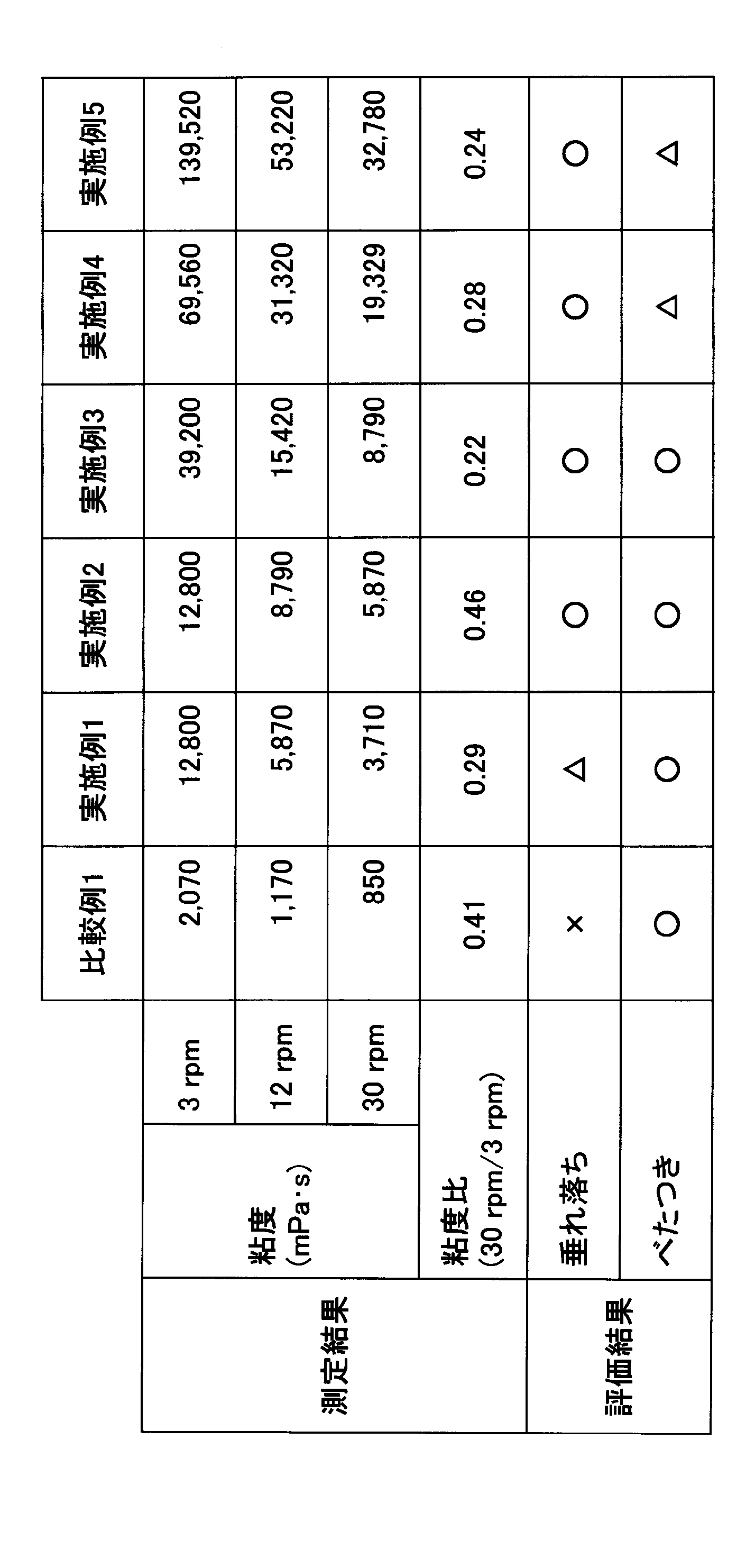
表1の結果から本実施形態に併用する基剤について、B型粘度計における基剤温度30℃での回転速度3rpmの粘度に対する回転速度30rpmの粘度の比は0.5以下、より好ましくは0.3以下にすればよい。かつ、本実施形態の基剤の回転速度12rpmの粘度は2500~100000mPa・sにすればよい。より好ましくは5000~50000mPa・s、さらには5000~30000mPa・sにすればよい。そのようなチクソトロピー性を有する基剤を用いることによって、心地よくケアすることができる。
チクソトロピー性を基剤に付与するためには増粘剤を1種または2種以上を配合すると良い。前記増粘剤は特に限定されることはないが、例えば、天然の水溶性高分子の増粘剤としては、アラアビアガム、トラガカントガム、ガラクタン、グアーガム、ローカストビーンガム、タマリントガム、キャロブガム、カラヤガム、カラギーナン、ペクチン、カンテン、クインスシード(マルメロ)、アルゲコロイド(カッソウエキス)、デンプン(コメ、トウモロコシ、バレイショ、コムギ)、グリチルリチン酸等の植物系水溶性高分子;キサンタンガム、デキストラン、サクシノグリカン、ブルラン等の微生物系水溶性高分子;コラーゲン、カゼイン、アルブミン、ゼラチン等の動物系水溶性高分子などが例示される。
半合成水溶性高分子の増粘剤としては、カルボキシメチルデンプン、メチルヒドロキシプロピル、デンプン等のデンプン系水溶性高分子;メチルセルロース、ニトロセルロース、エチルセルロース、メチルヒドロキシプロピルセルロース、ヒドロキシエチルセルロース、セルロース硫酸ナトリウム、ヒドロキシプロピルセルロース、カルボキシメチルセルロース(CMC)、結晶セルロース、セルロース末等のセルロース系水溶性高分子;アルギン酸ナトリウム、アルギン酸プロピレングリコールエステル等のアルギン酸系水溶性高分子などが例示される。
合成水溶性高分子の増粘剤としては、ポリビニルアルコール、ポリビニルメチルエーテル、ポリビニルピロリドン、カルボキシビニルポリマー(カーボポール)等のビニル系水溶性高分子;ポリエチレングリコール20,000、同4,000,000、同600,000等のポリオキシエチレン系水溶性高分子;ポリオキシエチレンポリオキシプロピレン共重合体等の共重合系水溶性高分子;ポリアクリル酸ナトリウム、ポリエチルアクリレート、ポリアクリルアミド等のアクリル系水溶性高分子のほか、ポリエチレンイミン、カチオンポリマーなどが例示される。
無機粉体の増粘剤としては、ベントナイト、ケイ酸AlMg(ビーガム)、ラポナイト、ヘクトライト、無水ケイ酸などが例示される。粉末成分としては、疎水性粉末、親水性粉末のいずれも用いることができ、表面が処理されていても良い。
なお、これら増粘剤で固化した組成物を解砕処理して、固化物の立体障壁により構造を持たせたミクロゲル構造を有しても良い。
特に、このミクロゲル構造を有する増粘剤、または処理を用いると少量の配合で特性の付与が容易である。例えば、水溶性増粘剤であれば、カルボキシビニルポリマー、粘土鉱物、無水ケイ酸、結晶セルロースが良い。
また、チクソトロピー性を基剤に付与するためには乳化構造をとると良い。特に、水中油型を用いると水溶性増粘剤の効果をより発揮できる。この時の乳化に使用する乳化剤としては、油相中への溶解性が低く温度安定性がよいことから親水性界面活性剤が好ましく、特に総HLBが10以上である1種または2種以上から構成されるものが好適である。例えばグリセリン又はポリグリセリン脂肪酸エステル類、プロピレングリコール脂肪酸エステル類、POEソルビタン脂肪酸エステル類、POEソルビット脂肪酸エステル類、POEグリセリン脂肪酸エステル類、POE脂肪酸エステル類、POEアルキルエーテル類、POEアルキルフェニルエーテル類、POE・POPアルキルエーテル類、POEヒマシ油又は硬化ヒマシ油誘導体、POE蜜ロウ・ラノリン誘導体、アルカノールアミド類、POEプロピレングリコール脂肪酸エステル類、POEアルキルアミン、POE脂肪酸アミド等から選択される1種または2種以上を配合する。ただし、これらの例示に限定されるものではない。
また、基剤500は通常化粧料に配合される得る成分であれば特に限定されるものでなく、例えば、シリコーン油、エステル油、炭化水素油、紫外線吸収剤、高級脂肪酸、高級アルコール、油脂、ロウ、乳化剤、分散剤、低級アルコール、保湿剤、防腐剤、消炎剤、血行促進剤、抗炎症剤、美白剤、抗脂漏剤、賦活剤、香料、塩、各種抽出物、粉末、酸化チタン、酸化亜鉛、無機色材、有機色材、パール剤等が挙げられる。なお、粉末は表面処理されていても良い。ただし、これらの例示に限定されるものではない。
さらに、付加装置134によって基剤の特性を変更するようにしてもよい。加熱装置又は冷却装置を備える場合には、動作温度で物性変化することが好ましい。例えば、35℃~70℃又は5℃~15℃で結果として粘度が増減するようにすることが好ましい。また、振動装置を備える場合には振動周波数で物性変化することが好ましい。例えば、20kHz~10MHzで結果として粘度が増減するようにすることが好ましい。また、光照射装置を備える場合には、その波長で物性変化することが好ましい。例えば、450nm~750nmで結果として粘度が増減するようにすることが好ましい。また、パルス電流発生装置を備える場合には、そのパルス波高で物性変化することが好ましい。例えば、0.001mA~10mAで結果として粘度が増減するようにすることが好ましい。また、磁気発生装置を備える場合には、その磁束密度で物性変化することが好ましい。例えば、0.00001T(テスラ)~10T(テスラ)で結果として粘度が増減するようにすることが好ましい。
また、電位差を発生させるパルス電流発生装置を備える場合には、その電位差に応答して化粧成分の浸透が速くなるような成分を含む基剤を用いることが好ましい。特にその基剤の成分には、美白、保湿を目的とする成分が含まれることが好ましい。
なお、容器本体内に収納するものは基剤に限らない。例えば、皮膚面を清潔に保つための除菌用布や化粧料であってもよい。
次に、美容器具100を用いる美容のためのマッサージ方法について説明する。
図6は、本実施形態に係る美容器具100の処理フローチャートの一例である。ここでは、例として、付加装置134に加熱装置を用いた場合について説明する。
制御部132は、付加装置134の動作を開始し、動作を開始してからの時間を計時部136で計測し、所定の時間が経過した場合に動作を終了するように制御する。例えば、付加装置134が動作を開始してから所定の時間(例えば、3分、等。)したら動作を終了とする。
処理を開始すると、美容器具100の制御部132は、操作部138、例えば、スイッチ、が操作されたかどうか調べる(ステップS10)。操作部138が操作されていない場合には、操作されるまでステップS10を繰り返す。
操作部138が操作された場合には、制御部132は、付加装置134である加熱装置を起動させる(ステップS20)。起動した付加装置134である加熱装置は、本体121の底面部124、側面部125、中間部126を加熱して目標温度になるように制御する。目標温度は、例えば、40℃である。
制御部132は、付加装置134である加熱装置を起動してから3分経過したかどうかを判定する(ステップS30)。3分経過していない場合は、ステップS30を繰り返す。3分経過した場合には、制御部132は、付加装置134である加熱装置を停止させる(ステップS40)。そして、処理は終了する。なお、処理終了後は再度処理を開始することによって、繰り返し処理を行うようにしてよい。
上述のように、所定の時間が経過すると動作を終了させることによって、例えば低温やけど等を防止することができる。また、加熱装置等を動作させたままにすることがないことから、火災防止等の安全性を高めることができる。さらには、無駄な電力を使うことないことからエネルギーの無駄な消費を抑えることができる。
図7A、図7Bは、本実施形態に係る美容器具100を用いる美容のためのマッサージ方法を説明する図である。図7Aは、首筋のような緩やかな曲面の肌面300を施術面として美容器具100の使用する場合の図である。図7Bは、鎖骨周りのような複雑な面の肌面400を施術面として美容器具100の使用する場合の図である。
最初に、図1の容器200に収納されている基剤500を肌(皮膚)に塗布(適用)する。また、美容器具100の付加装置134を起動する。そして、美容器具100を図7Aのような緩やかな曲面の肌面300を施術面として美容器具100の使用する場合には、底面部124(及び中間部126)を施術面に押し当てる。また、図7Bのように複雑な面の肌面400を施術面として美容器具100の使用する場合には、側面部125(及び中間部126)を施術面に押し当てる。
なお、本実施形態に係るマッサージ用美容機器1を用いて美容のためのマッサージを行う際には、大別すると(1)美容器具100のマッサージヘッド部120のみ、(2)美容器具100のマッサージヘッド部120と付加装置134の組み合わせ、(3)美容器具100のマッサージヘッド部120と基剤500の組み合わせ、(4)美容器具100のマッサージヘッド部120と付加装置134、基剤500の組み合わせ、等様々な種類のマッサージ方法を採用することができる。
(1)美容器具100のマッサージヘッド部120のみによるマッサージは、マッサージヘッド部120を施術面に押し当てることにより行うマッサージである。この場合には、付加装置134は動作させない。なお、付加装置134を備えていない美容器具100を用いてもよい。本実施形態のマッサージヘッド部120を用いることによって、マッサージの際に、多様な形状の肌面に対し、マッサージヘッド部120を肌に密着させることができる。
(2)美容器具100のマッサージヘッド部120と付加装置134の組み合わせによるマッサージは、付加装置134を動作させながらマッサージヘッド部120を施術面に押し当てて行うマッサージである。美容器具100のマッサージヘッド部120に付加装置134を組み合わせることによって、更に、温度、電気、電磁波、振動等の刺激を加えながらマッサージを行うことができる。
(3)美容器具100のマッサージヘッド部120と基剤500の組み合わせによるマッサージは、施術面に基剤500を適用してから、マッサージヘッド部120を施術面に押し当てることにより行うマッサージである。この場合には、(1)と同様に、付加装置134は動作させない。なお、付加装置134を備えていない美容器具100を用いてもよい。美容器具100のマッサージヘッド部120に基剤500を組み合わせることによって、更に、マッサージの際に肌への摩擦を低減することが可能になる。また、基剤500により、肌へ水分や美容成分を補給することできる。
(4)美容器具100のマッサージヘッド部120と付加装置134、基剤500の組み合わせによるマッサージは、施術面に基剤500を適用してから、付加装置134を動作させながらマッサージヘッド部120を施術面に押し当てて行うマッサージである。この場合は、上述のように、付加装置134に適合する基剤500を用いることが好ましい。美容器具100のマッサージヘッド部120に付加装置134及び基剤500を組み合わせることによって、更に、付加装置134により基剤500の効果を向上させることができる。
このように、本実施形態において、底面部124(及び中間部126)を用いることによって、緩やかな曲面の肌面に基剤を広い面に塗りやすくなっている。また、側面部125を用いることによって、底面部124を押し当てることができないような施術面にも、マッサージヘッドを押し当てることができる。
次に、本実施形態に係る美容器具100の変形例について説明する。
図8は、変形例の美容器具150の本体171の断面図及び平面図である。
本体171は、本体121と同様に、上面部173と、上面部173に対向する底面部174と、上面部173と底面部174との間に側面部175とを備える。また、底面部174と側面部175の間に中間部176を備える。また、本体121と同様に、上面部173の中心には、開口部172が形成されている。上面部173側から見た平面視で、側面部175の外周部分を最外周部178という場合がある。
本体171では、側面部175の外面は、中心軸Xを通る断面形状が、最小半径がRB1、最大半径がRB2(=RB)の円弧である曲面である。すなわち、側面部175の平面視の位置によって、側面部175の外面の曲率が異なる。本変形例では、図8の一番右側が最小半径、一番左側が最大半径になっている。
なお、最小半径、最大半径の位置は、図8の開示に限らず適宜変更してもよい。また、最小半径と最大半径の間の半径については、適宜変化するにすればよい。例えば、最小半径の位置との角度に比例する半径としてもよい。
図9A、図9Bは、変形例の美容器具150を用いる美容のためのマッサージ方法を説明する図である。
図9Bの肌面600は、図7B(図9A)の肌面400より複雑になっている。肌面400に対しては、側面部175の断面形状が半径RB2の円弧である部分を押し当てる。肌面600に対しては、側面部175の断面形状が半径RB1の円弧である部分を押し当てる。このようにして、更に複雑な肌面に対しても、マッサージヘッドを密着させることができる。
なお、マッサージ用美容機器1は、首や首から胸元にかけての部位であるデコルテに限らず、例えば、顔や腕、脚等に用いてもよい。
以上、本発明を実施例に基づいて説明したが、本発明は上記実施例に限定されるものではなく、特許請求の範囲に記載の範囲内で様々な変形が可能である。
本願は、日本特許庁に2018年11月19日に出願された基礎出願特願2018-216533号の優先権を主張するものであり、その全内容を参照によりここに援用する。
1 マッサージ用美容機器
100 美容器具
110 取っ手部
120 マッサージヘッド部
121 本体
122 開口部
123 上面部
124 底面部
125 側面部
126 中間部
128 最外周部
134 付加装置
200 容器
222 収納部
500 基剤
X 中心軸
100 美容器具
110 取っ手部
120 マッサージヘッド部
121 本体
122 開口部
123 上面部
124 底面部
125 側面部
126 中間部
128 最外周部
134 付加装置
200 容器
222 収納部
500 基剤
X 中心軸
Claims (14)
- ヘッド部と、前記ヘッド部に取り付けられた取っ手部と、を備える器具であって、
前記ヘッド部は、
上面部に開口部を有する本体を備え、
前記本体は、前記上面部に対向する底面部と、前記上面部と前記底面部との間に側面部とを有し、
前記側面部の外面は、前記側面部の最外周部より内側にある前記上面部、前記最外周部及び前記最外周部より内側にある前記底面部に至る外側に凸である曲面を1つ以上有し、
前記本体は、一体物として形成されていること
を特徴とする器具。 - 前記本体は、金属であること
を特徴とする請求項1に記載の器具。 - 前記金属は、アルミニウムであること
を特徴とする請求項2に記載の器具。 - 前記本体の外面には、低摩擦コーティングが施されていること
を特徴とする請求項1~3のいずれか1項に記載の器具。 - 前記低摩擦コーティングは、フッ素コーティングであること
を特徴とする請求項4に記載の器具。 - 前記底面部の外面は断面形状が外側に凸及び半径RAの円弧である曲面であり、
前記側面部の外面は断面形状が外側に凸及び半径RBの円弧である曲面であり、
RA>RBであること
を特徴とする請求項1~5のいずれか1項に記載の器具。 - 前記底面部と前記側面部との間に中間部を有し、
前記中間部の外面は断面形状が外側に凸及び半径RCの円弧である曲面であり、
RA>RC>RBであること
を特徴とする請求項6に記載の器具。 - 前記本体は、中心軸に対して回転対称であること
を特徴とする請求項1~7のいずれか1項に記載の器具。 - 前記ヘッド部は、前記本体の内部に付加装置を備えること
を特徴とする請求項1~8のいずれか1項に記載の器具。 - 前記付加装置は、加熱装置、冷却装置、振動発生装置、電磁波発生装置のいずれか1つ又は2以上の組み合わせであること
を特徴とする請求項9に記載の器具。 - 前記加熱装置は、ヒータであること
を特徴とする請求項10に記載の器具。 - 請求項1~11のいずれか1項に記載の器具と、
マッサージの際に皮膚に適用する基剤を収容する容器を備え、
前記容器の上面には、前記ヘッド部を収納可能な収納部を備えること
を特徴とするマッサージ用美容機器。 - 前記基剤は、B型粘度計における基剤温度30℃での回転速度3rpmの粘度に対する回転速度30rpmの粘度の比が0.5以下であり、かつ、回転速度12rpmの粘度が2500~100000mPa・sであること
を特徴とする請求項12に記載のマッサージ用美容機器。 - ヘッド部と、前記ヘッド部に取り付けられた取っ手部と、を備える器具を用いる美容のためのマッサージ方法であって、
前記ヘッド部は、
上面部に開口部を有する本体を備え、
前記本体は、前記上面部に対向する底面部と、前記上面部と前記底面部との間に側面部とを有し、
前記側面部の外面は、前記側面部の最外周部より内側にある前記上面部、前記最外周部及び前記最外周部より内側にある前記底面部に至る外側に凸である曲面を1つ以上有し、
前記本体は、一体物として形成されており、
基剤を皮膚に適用して前記基剤が適用された皮膚を前記ヘッド部を用いてマッサージすること
を特徴とする美容のためのマッサージ方法。
Priority Applications (2)
| Application Number | Priority Date | Filing Date | Title |
|---|---|---|---|
| JP2020558386A JP7346448B2 (ja) | 2018-11-19 | 2019-11-18 | 美容器具及びマッサージ用美容機器 |
| CN201980075619.XA CN113038917A (zh) | 2018-11-19 | 2019-11-18 | 按摩用美容仪器和用于美容的按摩方法 |
Applications Claiming Priority (2)
| Application Number | Priority Date | Filing Date | Title |
|---|---|---|---|
| JP2018-216533 | 2018-11-19 | ||
| JP2018216533 | 2018-11-19 |
Publications (1)
| Publication Number | Publication Date |
|---|---|
| WO2020105592A1 true WO2020105592A1 (ja) | 2020-05-28 |
Family
ID=70773684
Family Applications (1)
| Application Number | Title | Priority Date | Filing Date |
|---|---|---|---|
| PCT/JP2019/045117 Ceased WO2020105592A1 (ja) | 2018-11-19 | 2019-11-18 | マッサージ用美容機器、美容のためのマッサージ方法 |
Country Status (3)
| Country | Link |
|---|---|
| JP (1) | JP7346448B2 (ja) |
| CN (1) | CN113038917A (ja) |
| WO (1) | WO2020105592A1 (ja) |
Cited By (2)
| Publication number | Priority date | Publication date | Assignee | Title |
|---|---|---|---|---|
| JP7369824B1 (ja) | 2022-06-02 | 2023-10-26 | 修一 清水 | 骨格振動器具および施術方法 |
| JP2025006454A (ja) * | 2023-06-29 | 2025-01-17 | 昌治 平野 | 経皮薬液浸潤、血流促進、及び細胞活性装置 |
Citations (2)
| Publication number | Priority date | Publication date | Assignee | Title |
|---|---|---|---|---|
| JP2013236650A (ja) * | 2012-05-11 | 2013-11-28 | Daiko Kagaku Kogyo Kk | 押圧器具 |
| JP2016120107A (ja) * | 2014-12-25 | 2016-07-07 | コーニンクレッカ フィリップス エヌ ヴェKoninklijke Philips N.V. | マッサージ装置 |
Family Cites Families (16)
| Publication number | Priority date | Publication date | Assignee | Title |
|---|---|---|---|---|
| AT334245B (de) * | 1975-01-10 | 1976-01-10 | Philips Nv | Elektromotorisch angetriebenes gerat |
| JPS5362190U (ja) * | 1976-10-29 | 1978-05-26 | ||
| JPS6343664A (ja) * | 1986-08-08 | 1988-02-24 | 森下 弘 | 美容器 |
| JP3051693U (ja) | 1997-11-28 | 1998-09-02 | 株式会社プリズム・リラ | チタン鋼を用いたエステティック用プローブ |
| CN2604990Y (zh) * | 2003-04-01 | 2004-03-03 | 杜家义 | 手持式按摩器 |
| CN2810582Y (zh) * | 2005-07-11 | 2006-08-30 | 游象扬 | 具推锥作用的刮痧保健器 |
| KR200452383Y1 (ko) * | 2009-03-09 | 2011-02-22 | (주)아모레퍼시픽 | 뚜껑에 융기되는 퍼프가 설치된 화장품 용기 |
| JP3183106U (ja) | 2013-02-13 | 2013-04-25 | 株式会社トキワ | 塗布具付き化粧料容器 |
| JP6266935B2 (ja) * | 2013-09-26 | 2018-01-24 | 株式会社平垣製作所 | 温灸器 |
| JP6218039B2 (ja) * | 2014-05-29 | 2017-10-25 | パナソニックIpマネジメント株式会社 | 美容装置 |
| CN204562841U (zh) * | 2015-04-03 | 2015-08-19 | 陈华 | 美容按摩器 |
| FR3036598B1 (fr) | 2015-05-26 | 2018-09-21 | L'oreal | Dispositif d'application et de massage |
| FR3040135B1 (fr) * | 2015-08-18 | 2017-09-15 | Seb Sa | Appareil de massage muni d'au moins une composition cosmetique, dermatologique et/ou pharmaceutique |
| KR101768442B1 (ko) * | 2015-08-27 | 2017-08-16 | 박규리 | 마사지 용구 |
| TW201811224A (zh) | 2016-06-16 | 2018-04-01 | 日商Mtg股份有限公司 | 按壓器具 |
| CN107951693A (zh) * | 2017-12-14 | 2018-04-24 | 东莞市谦禾电子科技有限公司 | 新型按摩器具 |
-
2019
- 2019-11-18 JP JP2020558386A patent/JP7346448B2/ja active Active
- 2019-11-18 WO PCT/JP2019/045117 patent/WO2020105592A1/ja not_active Ceased
- 2019-11-18 CN CN201980075619.XA patent/CN113038917A/zh active Pending
Patent Citations (2)
| Publication number | Priority date | Publication date | Assignee | Title |
|---|---|---|---|---|
| JP2013236650A (ja) * | 2012-05-11 | 2013-11-28 | Daiko Kagaku Kogyo Kk | 押圧器具 |
| JP2016120107A (ja) * | 2014-12-25 | 2016-07-07 | コーニンクレッカ フィリップス エヌ ヴェKoninklijke Philips N.V. | マッサージ装置 |
Cited By (3)
| Publication number | Priority date | Publication date | Assignee | Title |
|---|---|---|---|---|
| JP7369824B1 (ja) | 2022-06-02 | 2023-10-26 | 修一 清水 | 骨格振動器具および施術方法 |
| JP2023177715A (ja) * | 2022-06-02 | 2023-12-14 | 修一 清水 | 骨格振動器具および施術方法 |
| JP2025006454A (ja) * | 2023-06-29 | 2025-01-17 | 昌治 平野 | 経皮薬液浸潤、血流促進、及び細胞活性装置 |
Also Published As
| Publication number | Publication date |
|---|---|
| CN113038917A (zh) | 2021-06-25 |
| JP7346448B2 (ja) | 2023-09-19 |
| JPWO2020105592A1 (ja) | 2021-09-30 |
Similar Documents
| Publication | Publication Date | Title |
|---|---|---|
| KR101096600B1 (ko) | 미안용 마스크 | |
| AU2011302478B2 (en) | Device and method for stimulating the meibomian glands of the eyelid | |
| KR101478162B1 (ko) | 휴대형 피부미용기 및 그의 제어방법 | |
| CN108135350B (zh) | 用于面部刷的加热和冷却供给 | |
| TWI658837B (zh) | 具有改進的使用感覺之發泡體 | |
| US20050148910A1 (en) | Apparatus having a skin-contactable element containing an agent | |
| WO2018097202A1 (ja) | 化粧料用被膜の製造方法 | |
| US20150164734A1 (en) | System and Method for Cosmetic Enhancement of Lips | |
| EP3160414B1 (en) | A bodycare device | |
| FR2867675B1 (fr) | Composition cosmetique comprenant des particules concaves | |
| US20110167640A1 (en) | Skin-heating shaving apparatus and method | |
| WO2017069080A1 (ja) | 被膜の製造方法 | |
| JP2012521815A (ja) | 化粧用途および/または医療用途のための塗布装置 | |
| JP7346448B2 (ja) | 美容器具及びマッサージ用美容機器 | |
| JP7041622B2 (ja) | スポンジ又は発泡体要素を備えたブラシ | |
| JP2019156853A (ja) | 被膜の製造方法 | |
| KR20170101012A (ko) | 갈바닉 피부 마사지 장치 | |
| CA2456316A1 (en) | Electric heat therapy technique and instrument | |
| Dayan et al. | A prospective trial: handsfree thermoregulated bipolar radiofrequency for face and neck contouring | |
| WO2018194083A1 (ja) | 化粧被膜の製造方法 | |
| JP2011522576A (ja) | 皮膚のたるみおよびシワを防ぐための機器 | |
| KR20260042413A (ko) | 가변적인 점도를 갖는 화장료 조성물 및 이를 포함하는 화장품 | |
| AU7682700A (en) | A swab for make-up removal | |
| NL9100277A (nl) | Massage apparaat. | |
| EP1880697A1 (en) | A skin care method using wax and the apparatus thereof |
Legal Events
| Date | Code | Title | Description |
|---|---|---|---|
| 121 | Ep: the epo has been informed by wipo that ep was designated in this application |
Ref document number: 19887301 Country of ref document: EP Kind code of ref document: A1 |
|
| ENP | Entry into the national phase |
Ref document number: 2020558386 Country of ref document: JP Kind code of ref document: A |
|
| NENP | Non-entry into the national phase |
Ref country code: DE |
|
| 122 | Ep: pct application non-entry in european phase |
Ref document number: 19887301 Country of ref document: EP Kind code of ref document: A1 |