WO2020105503A1 - 表示制御プログラム、表示制御装置、及び表示制御方法 - Google Patents
表示制御プログラム、表示制御装置、及び表示制御方法Info
- Publication number
- WO2020105503A1 WO2020105503A1 PCT/JP2019/044294 JP2019044294W WO2020105503A1 WO 2020105503 A1 WO2020105503 A1 WO 2020105503A1 JP 2019044294 W JP2019044294 W JP 2019044294W WO 2020105503 A1 WO2020105503 A1 WO 2020105503A1
- Authority
- WO
- WIPO (PCT)
- Prior art keywords
- player character
- particles
- player
- control unit
- display control
- Prior art date
- Legal status (The legal status is an assumption and is not a legal conclusion. Google has not performed a legal analysis and makes no representation as to the accuracy of the status listed.)
- Ceased
Links
Images


Classifications
-
- G—PHYSICS
- G02—OPTICS
- G02B—OPTICAL ELEMENTS, SYSTEMS OR APPARATUS
- G02B27/00—Optical systems or apparatus not provided for by any of the groups G02B1/00 - G02B26/00, G02B30/00
- G02B27/01—Head-up displays
- G02B27/017—Head mounted
- G02B27/0172—Head mounted characterised by optical features
-
- A—HUMAN NECESSITIES
- A63—SPORTS; GAMES; AMUSEMENTS
- A63F—CARD, BOARD, OR ROULETTE GAMES; INDOOR GAMES USING SMALL MOVING PLAYING BODIES; VIDEO GAMES; GAMES NOT OTHERWISE PROVIDED FOR
- A63F13/00—Video games, i.e. games using an electronically generated display having two or more dimensions
- A63F13/25—Output arrangements for video game devices
-
- A—HUMAN NECESSITIES
- A63—SPORTS; GAMES; AMUSEMENTS
- A63F—CARD, BOARD, OR ROULETTE GAMES; INDOOR GAMES USING SMALL MOVING PLAYING BODIES; VIDEO GAMES; GAMES NOT OTHERWISE PROVIDED FOR
- A63F13/00—Video games, i.e. games using an electronically generated display having two or more dimensions
- A63F13/40—Processing input control signals of video game devices, e.g. signals generated by the player or derived from the environment
- A63F13/42—Processing input control signals of video game devices, e.g. signals generated by the player or derived from the environment by mapping the input signals into game commands, e.g. mapping the displacement of a stylus on a touch screen to the steering angle of a virtual vehicle
- A63F13/428—Processing input control signals of video game devices, e.g. signals generated by the player or derived from the environment by mapping the input signals into game commands, e.g. mapping the displacement of a stylus on a touch screen to the steering angle of a virtual vehicle involving motion or position input signals, e.g. signals representing the rotation of an input controller or a player's arm motions sensed by accelerometers or gyroscopes
-
- A—HUMAN NECESSITIES
- A63—SPORTS; GAMES; AMUSEMENTS
- A63F—CARD, BOARD, OR ROULETTE GAMES; INDOOR GAMES USING SMALL MOVING PLAYING BODIES; VIDEO GAMES; GAMES NOT OTHERWISE PROVIDED FOR
- A63F13/00—Video games, i.e. games using an electronically generated display having two or more dimensions
- A63F13/50—Controlling the output signals based on the game progress
- A63F13/52—Controlling the output signals based on the game progress involving aspects of the displayed game scene
- A63F13/525—Changing parameters of virtual cameras
- A63F13/5255—Changing parameters of virtual cameras according to dedicated instructions from a player, e.g. using a secondary joystick to rotate the camera around a player's character
-
- A—HUMAN NECESSITIES
- A63—SPORTS; GAMES; AMUSEMENTS
- A63F—CARD, BOARD, OR ROULETTE GAMES; INDOOR GAMES USING SMALL MOVING PLAYING BODIES; VIDEO GAMES; GAMES NOT OTHERWISE PROVIDED FOR
- A63F13/00—Video games, i.e. games using an electronically generated display having two or more dimensions
- A63F13/55—Controlling game characters or game objects based on the game progress
- A63F13/57—Simulating properties, behaviour or motion of objects in the game world, e.g. computing tyre load in a car race game
- A63F13/577—Simulating properties, behaviour or motion of objects in the game world, e.g. computing tyre load in a car race game using determination of contact between game characters or objects, e.g. to avoid collision between virtual racing cars
-
- A—HUMAN NECESSITIES
- A63—SPORTS; GAMES; AMUSEMENTS
- A63F—CARD, BOARD, OR ROULETTE GAMES; INDOOR GAMES USING SMALL MOVING PLAYING BODIES; VIDEO GAMES; GAMES NOT OTHERWISE PROVIDED FOR
- A63F13/00—Video games, i.e. games using an electronically generated display having two or more dimensions
- A63F13/60—Generating or modifying game content before or while executing the game program, e.g. authoring tools specially adapted for game development or game-integrated level editor
- A63F13/65—Generating or modifying game content before or while executing the game program, e.g. authoring tools specially adapted for game development or game-integrated level editor automatically by game devices or servers from real world data, e.g. measurement in live racing competition
-
- G—PHYSICS
- G02—OPTICS
- G02B—OPTICAL ELEMENTS, SYSTEMS OR APPARATUS
- G02B27/00—Optical systems or apparatus not provided for by any of the groups G02B1/00 - G02B26/00, G02B30/00
- G02B27/0093—Optical systems or apparatus not provided for by any of the groups G02B1/00 - G02B26/00, G02B30/00 with means for monitoring data relating to the user, e.g. head-tracking, eye-tracking
-
- G—PHYSICS
- G02—OPTICS
- G02B—OPTICAL ELEMENTS, SYSTEMS OR APPARATUS
- G02B27/00—Optical systems or apparatus not provided for by any of the groups G02B1/00 - G02B26/00, G02B30/00
- G02B27/01—Head-up displays
- G02B27/017—Head mounted
-
- G—PHYSICS
- G02—OPTICS
- G02B—OPTICAL ELEMENTS, SYSTEMS OR APPARATUS
- G02B27/00—Optical systems or apparatus not provided for by any of the groups G02B1/00 - G02B26/00, G02B30/00
- G02B27/01—Head-up displays
- G02B27/0179—Display position adjusting means not related to the information to be displayed
-
- G—PHYSICS
- G06—COMPUTING OR CALCULATING; COUNTING
- G06F—ELECTRIC DIGITAL DATA PROCESSING
- G06F3/00—Input arrangements for transferring data to be processed into a form capable of being handled by the computer; Output arrangements for transferring data from processing unit to output unit, e.g. interface arrangements
- G06F3/01—Input arrangements or combined input and output arrangements for interaction between user and computer
- G06F3/048—Interaction techniques based on graphical user interfaces [GUI]
- G06F3/0481—Interaction techniques based on graphical user interfaces [GUI] based on specific properties of the displayed interaction object or a metaphor-based environment, e.g. interaction with desktop elements like windows or icons, or assisted by a cursor's changing behaviour or appearance
-
- G—PHYSICS
- G06—COMPUTING OR CALCULATING; COUNTING
- G06T—IMAGE DATA PROCESSING OR GENERATION, IN GENERAL
- G06T13/00—Animation
- G06T13/20—3D [Three Dimensional] animation
-
- G—PHYSICS
- G06—COMPUTING OR CALCULATING; COUNTING
- G06T—IMAGE DATA PROCESSING OR GENERATION, IN GENERAL
- G06T13/00—Animation
- G06T13/20—3D [Three Dimensional] animation
- G06T13/40—3D [Three Dimensional] animation of characters, e.g. humans, animals or virtual beings
-
- G—PHYSICS
- G06—COMPUTING OR CALCULATING; COUNTING
- G06T—IMAGE DATA PROCESSING OR GENERATION, IN GENERAL
- G06T19/00—Manipulating 3D models or images for computer graphics
-
- A—HUMAN NECESSITIES
- A63—SPORTS; GAMES; AMUSEMENTS
- A63F—CARD, BOARD, OR ROULETTE GAMES; INDOOR GAMES USING SMALL MOVING PLAYING BODIES; VIDEO GAMES; GAMES NOT OTHERWISE PROVIDED FOR
- A63F13/00—Video games, i.e. games using an electronically generated display having two or more dimensions
- A63F13/50—Controlling the output signals based on the game progress
- A63F13/54—Controlling the output signals based on the game progress involving acoustic signals, e.g. for simulating revolutions per minute [RPM] dependent engine sounds in a driving game or reverberation against a virtual wall
-
- A—HUMAN NECESSITIES
- A63—SPORTS; GAMES; AMUSEMENTS
- A63F—CARD, BOARD, OR ROULETTE GAMES; INDOOR GAMES USING SMALL MOVING PLAYING BODIES; VIDEO GAMES; GAMES NOT OTHERWISE PROVIDED FOR
- A63F2300/00—Features of games using an electronically generated display having two or more dimensions, e.g. on a television screen, showing representations related to the game
- A63F2300/60—Methods for processing data by generating or executing the game program
- A63F2300/66—Methods for processing data by generating or executing the game program for rendering three dimensional images
- A63F2300/6638—Methods for processing data by generating or executing the game program for rendering three dimensional images for simulating particle systems, e.g. explosion, fireworks
-
- A—HUMAN NECESSITIES
- A63—SPORTS; GAMES; AMUSEMENTS
- A63F—CARD, BOARD, OR ROULETTE GAMES; INDOOR GAMES USING SMALL MOVING PLAYING BODIES; VIDEO GAMES; GAMES NOT OTHERWISE PROVIDED FOR
- A63F2300/00—Features of games using an electronically generated display having two or more dimensions, e.g. on a television screen, showing representations related to the game
- A63F2300/80—Features of games using an electronically generated display having two or more dimensions, e.g. on a television screen, showing representations related to the game specially adapted for executing a specific type of game
- A63F2300/8082—Virtual reality
-
- G—PHYSICS
- G02—OPTICS
- G02B—OPTICAL ELEMENTS, SYSTEMS OR APPARATUS
- G02B27/00—Optical systems or apparatus not provided for by any of the groups G02B1/00 - G02B26/00, G02B30/00
- G02B27/01—Head-up displays
- G02B27/0101—Head-up displays characterised by optical features
- G02B2027/0138—Head-up displays characterised by optical features comprising image capture systems, e.g. camera
-
- G—PHYSICS
- G02—OPTICS
- G02B—OPTICAL ELEMENTS, SYSTEMS OR APPARATUS
- G02B27/00—Optical systems or apparatus not provided for by any of the groups G02B1/00 - G02B26/00, G02B30/00
- G02B27/01—Head-up displays
- G02B27/0101—Head-up displays characterised by optical features
- G02B2027/014—Head-up displays characterised by optical features comprising information/image processing systems
-
- G—PHYSICS
- G02—OPTICS
- G02B—OPTICAL ELEMENTS, SYSTEMS OR APPARATUS
- G02B27/00—Optical systems or apparatus not provided for by any of the groups G02B1/00 - G02B26/00, G02B30/00
- G02B27/01—Head-up displays
- G02B27/0179—Display position adjusting means not related to the information to be displayed
- G02B2027/0187—Display position adjusting means not related to the information to be displayed slaved to motion of at least a part of the body of the user, e.g. head, eye
Definitions
- the present invention relates to display control technology, and more particularly to a display control program for controlling display on a display device, a display control device, and a display control method.
- a game that can be played by operating the controller etc. while wearing the head mounted display connected to the game machine on the head and watching the screen displayed on the head mounted display is gaining popularity.
- By using a head-mounted display it is possible to increase the immersive feeling in the visual world and further enhance the entertainment value of the game.
- an object of the present invention is to provide a display technique capable of giving a comfortable feeling to a viewer.
- a display control program includes an image generation unit that causes a computer to generate an image in a virtual three-dimensional space, and a plurality of particles arranged in the virtual three-dimensional space.
- An object control unit that controls an object
- a player character control unit that controls a player character that can be operated by the player and that is arranged in a virtual three-dimensional space
- a determination unit that determines whether or not the player character and the object are in contact with each other.
- an absorption control unit that executes an action indicating that a plurality of particles included in the object in contact with the player character are absorbed by the player character, To realize.
- This device is an image generation unit that generates an image of a virtual three-dimensional space, an object control unit that is arranged in the virtual three-dimensional space, controls an object including a plurality of particles, and is arranged in the virtual three-dimensional space.
- the player character control unit that controls the player character that can be operated by the player
- the determination unit that determines whether or not the player character and the object have contacted each other
- the determination unit that the player character and the object have contacted each other
- An absorption control unit that executes an action that represents a state in which a plurality of particles included in an object that has come into contact with the player character are absorbed by the player character.
- Yet another aspect of the present invention is a display control method.
- This method includes the steps of generating an image of a virtual three-dimensional space on a computer, controlling an object including a plurality of particles arranged in the virtual three-dimensional space, and a player arranged in the virtual three-dimensional space. Controlling the operable player character, determining whether the player character has come into contact with the object, and determining that the player character has come into contact with the object, the object that has come into contact with the player character Causing the computer to execute an action representing a state in which the plurality of particles included therein are absorbed by the player character.
- FIG. 3 is an external view of the head mounted display according to the embodiment.
- FIG. It is a functional block diagram of a head mounted display. It is a figure which shows the external appearance structure of an input device. It is a figure which shows the internal structure of an input device. It is a functional block diagram of a game device. It is a figure which shows the example of the game screen displayed on the display device of a head mounted display. It is a figure which shows the example of the object arrange
- the game device is an example of a display control device, and generates and displays an image of the game world in which objects and characters are arranged in a virtual three-dimensional space.
- objects such as animals and plants, and player characters that represent the player's body are composed of multiple light particles, and the image representation of the game world that represents a fantastic mental world is presented to the player.
- This visual expression corresponds to the fact that all substances are composed of elementary particles, and reminds the player that particles are the source of energy in the game world.
- the game device displays that particles forming the object are sucked into the player character while shining.
- players can experience a novel and comfortable feeling of healing, such as touching animals and plants, resonating with each other, and absorbing energy. This allows the player to improve his / her mental state through the game.
- Such image representation may be displayed on a stationary display device or a portable display device, but it is more effective to use a head mounted display (HMD).
- the game device sets the viewpoint position at the position of the eyes of the player character, and while changing the line-of-sight direction according to the direction of the head mounted display, renders and generates the virtual three-dimensional space in which the objects are arranged.
- the first-person view image is displayed on the head-mounted display.
- the player can have a deep immersive feeling as if he / she actually exists in the fantastic imagery world.
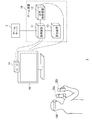
- FIG. 1 shows a configuration example of a game system 1 according to the embodiment.
- the game system 1 captures a game device 10, a head-mounted display 100, input devices 20a and 20b (collectively referred to as “input device 20”) that a player holds and operates, and a player wearing the head-mounted display 100. And an output device 15 for displaying an image.
- the output device 15 may be a television.
- the game device 10 is connected to an external network such as the Internet via an access point (AP) or the like.
- AP access point
- the game device 10 of the present embodiment is connected to a game server 3 provided to enable players of a plurality of game devices 10 to share a game world and execute a game at the same time.
- the game server 3 acquires information such as the position of the player character from each of the game devices 10 participating in the game, and distributes the acquired information to each game device 10.
- the head mounted display 100 is mounted on the head of the player to provide the player with a virtual reality (VR) image world.
- VR virtual reality
- the game device 10 includes a processing device 11, an output control device 12, and a storage device 13.
- the processing device 11 receives the operation information input by the player to the input device 20, the position information and the posture information of the input device 20 and the head mounted display 100, and executes the game application.
- the processing device 11 and the input device 20 may be connected by a cable or may be connected by a known wireless communication protocol.
- the output control device 12 is a processing unit that outputs the image data generated by the processing device 11 to the head-mounted display 100.
- the output control device 12 and the head-mounted display 100 may be connected by a cable, or a known wireless communication device. You may be connected by a communication protocol.
- the storage device 13 stores the program data of the game application, the shape data of the virtual three-dimensional space used by the game application, the shape data of the arranged objects and characters, and the like.
- the image capturing device 14 is a stereo camera, which captures the player wearing the head mounted display 100 at a predetermined cycle and supplies the captured image to the processing device 11.
- the head-mounted display 100 is provided with a marker (tracking LED) for tracking the head of the player, and the processing device 11 causes the head-mounted display 100 to move based on the position of the marker included in the captured image. Detect motion.
- a posture sensor (acceleration sensor and gyro sensor) is mounted on the head-mounted display 100, and the processing device 11 acquires sensor data detected by the posture sensor from the head-mounted display 100 to use a captured image of a marker.
- highly accurate tracking processing is performed.
- Various methods have been conventionally proposed for the tracking process, and the processing device 11 may employ any tracking method as long as it can detect the movement of the head mounted display 100.
- the input device 20 is provided with a marker (light emitting unit) for detecting the posture (for example, position and orientation) of the input device 20 in the physical space, and the processing device 11 is included in the captured image.
- the position and orientation of the input device 20 are detected based on the position / mode of the displayed marker.
- the input device 20 may be equipped with a posture sensor (for example, an acceleration sensor and a gyro sensor).
- the processing device 11 acquires the sensor data detected by the posture sensor from the input device 20, and instead of using the captured image of the marker, or together with the use of the captured image of the marker, the presence position of the input device 20 and The orientation may be detected. Note that other known methods may be adopted as long as the position and orientation of the input device 20 can be detected.
- the output device 15 Since the player views the image using the head mounted display 100, the output device 15 is not always necessary, but by preparing the output device 15, another viewer can view the image.
- the output control device 12 or the processing device 11 may display the same image as the image viewed by the player wearing the head mounted display 100 on the output device 15, or may display another image. For example, when the player wearing the head mounted display 100 and another viewer play the game together, the output device 15 may display a game image from the character viewpoint of the other viewer. Good.
- the head-mounted display 100 is a display device that displays an image on a display panel located in front of the player when worn by the player on the head.
- the head mounted display 100 separately displays an image for the left eye on the display panel for the left eye and an image for the right eye on the display panel for the right eye. These images form parallax images viewed from the left and right viewpoints and realize stereoscopic vision. Since the player views the display panel through the optical lens, the game device 10 supplies the parallax image data in which the optical distortion due to the lens is corrected to the head mounted display 100. Either the processing device 11 or the output control device 12 may perform this optical distortion correction processing.
- the function of the output control device 12 may be incorporated in the processing device 11. That is, the processing unit of the game device 10 may be configured by one processing device 11 or may be configured by the processing device 11 and the output control device 12. In the following, the function of providing the VR image to the head mounted display 100 will be collectively described as the function of the game device 10.
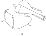
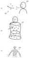
- FIG. 2 is an external view of the head mounted display 100 according to the embodiment.
- the head mounted display 100 includes a main body 110, a head contact portion 112, and a light emitting portion 114.
- the main body 110 is equipped with a display, a GPS unit for acquiring position information, an attitude sensor, a communication device, and the like.
- the head contact portion 112 may be provided with a biometric information acquisition sensor capable of measuring biometric information such as a player's body temperature, pulse, blood component, sweating, brain wave, and cerebral blood flow.
- the light emitting unit 114 emits light in a color instructed by the game device 10, and functions as a reference for calculating the position of the head mounted display 100 in the image captured by the image capturing device 14.
- the head-mounted display 100 may be further provided with a camera that captures the eyes of the player.
- the camera mounted on the head mounted display 100 can detect the line of sight of the player, the movement of the pupil, the blink, and the like.
- the display control technique of the present embodiment is not limited to the head mounted display 100 in a narrow sense, and may include glasses, glasses-type displays, glasses-type cameras, headphones, and headsets. (Headphones with microphone), earphones, earrings, ear-hook cameras, hats, hats with cameras, hair bands, etc. can also be applied.
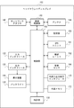
- FIG. 3 is a functional configuration diagram of the head mounted display 100.
- the head mounted display 100 includes an input interface 122, an output interface 130, a backlight 132, a communication control unit 140, a network adapter 142, an antenna 144, a storage unit 150, a GPS unit 161, a wireless unit 162, an attitude sensor 164, and external input / output terminals.
- An interface 170, an external memory 172, a clock unit 180, a display device 190, and a control unit 160 are provided.
- these components are realized by the CPU, memory, programs loaded in the memory, etc. of any computer.
- the functional blocks realized by their cooperation are depicted. Therefore, it will be understood by those skilled in the art that these functional blocks can be realized in various forms by only hardware, only software, or a combination thereof.
- the control unit 160 is a main processor that processes and outputs signals such as image signals and sensor signals, and commands and data.
- the input interface 122 receives an operation signal or a setting signal from an input button or the like and supplies it to the control unit 160.
- the output interface 130 receives the image signal from the control unit 160 and displays it on the display device 190.
- the backlight 132 supplies a backlight to the liquid crystal display that constitutes the display device 190.
- the communication control unit 140 transmits the data input from the control unit 160 to the outside by wired or wireless communication via the network adapter 142 or the antenna 144.
- the communication control unit 140 also receives data from the outside by wire or wireless communication via the network adapter 142 or the antenna 144, and outputs the data to the control unit 160.
- the storage unit 150 temporarily stores data, parameters, operation signals, etc. processed by the control unit 160.
- the GPS unit 161 receives position information from GPS satellites and supplies it to the control unit 160 according to an operation signal from the control unit 160.
- the wireless unit 162 receives the position information from the wireless base station and supplies it to the control unit 160 in accordance with the operation signal from the control unit 160.
- the attitude sensor 164 detects attitude information such as the orientation and inclination of the main body 110 of the head mounted display 100.
- the attitude sensor 164 is realized by appropriately combining a gyro sensor, an acceleration sensor, an angular acceleration sensor, and the like.
- the external input / output terminal interface 170 is an interface for connecting a peripheral device such as a USB (Universal Serial Bus) controller.
- the external memory 172 is an external memory such as a flash memory.
- the clock unit 180 sets time information by a setting signal from the control unit 160 and supplies the time data to the control unit 160.
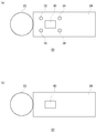
- FIG. 4 shows an external configuration of the input device 20.
- FIG. 4A shows the upper surface configuration of the input device 20, and
- FIG. 4B shows the lower surface configuration of the input device 20.
- the input device 20 includes a light emitter 22 and a handle 24.
- the light emitting body 22 is formed into a sphere on the outside with a resin having a light transmitting property, and has a light emitting element such as a light emitting diode or a light bulb inside. When the inner light emitting element emits light, the entire outer sphere glows.
- Operation buttons 30, 32, 34, 36, 38 are provided on the upper surface of the handle 24, and operation buttons 40 are provided on the lower surface.
- the player operates the operation buttons 30, 32, 34, 36, 38 with the thumb and the operation button 40 with the index finger while holding the end portion of the handle 24 with the hand.
- the operation buttons 30, 32, 34, 36, 38 are of a push-down type, and the player operates them by pushing them down.
- the operation button 40 may be capable of inputting an analog amount.
- FIG. 5 shows the internal configuration of the input device 20.
- the input device 20 includes a wireless communication module 48, a processing unit 50, a light emitting unit 62, and operation buttons 30, 32, 34, 36, 38, 40.
- the wireless communication module 48 has a function of transmitting and receiving data to and from the wireless communication module of the game device 10.
- the processing unit 50 executes intended processing in the input device 20.
- the processing unit 50 includes a main control unit 52, an input reception unit 54, a triaxial acceleration sensor 56, a triaxial gyro sensor 58, and a light emission control unit 60.
- the main control unit 52 transmits / receives necessary data to / from the wireless communication module 48.
- the input receiving unit 54 receives input information from the operation buttons 30, 32, 34, 36, 38, 40 and sends it to the main control unit 52.
- the triaxial acceleration sensor 56 detects acceleration components in the XYZ triaxial directions.
- the triaxial gyro sensor 58 detects angular velocities on the XZ plane, the ZY plane, and the YX plane.
- the width direction of the input device 20 is set as the X axis
- the height direction is set as the Y axis
- the longitudinal direction is set as the Z axis.
- the triaxial acceleration sensor 56 and the triaxial gyro sensor 58 are arranged in the handle 24 of the input device 20, and are preferably arranged near the center in the handle 24.
- the wireless communication module 48 transmits the information detected by the triaxial acceleration sensor 56 and the information detected by the triaxial gyro sensor 58 to the wireless communication module of the game apparatus 10 in a predetermined cycle together with the input information from the operation button. ..
- This transmission cycle is set to 11.25 ms, for example.
- the light emission control unit 60 controls the light emission of the light emitting unit 62.
- the light emitting unit 62 has a red LED 64a, a green LED 64b, and a blue LED 64c, and is capable of emitting light of a plurality of colors.
- the light emission control unit 60 adjusts the light emission of the red LED 64a, the green LED 64b, and the blue LED 64c to cause the light emitting unit 62 to emit a desired color.
- the wireless communication module 48 When the wireless communication module 48 receives the light emission instruction from the game device 10, the wireless communication module 48 supplies the light emission instruction to the main control unit 52, and the main control unit 52 supplies the light emission instruction to the light emission control unit 60.
- the light emission control unit 60 controls the light emission of the red LED 64a, the green LED 64b, and the blue LED 64c so that the light emitting unit 62 emits light in the color designated by the light emission instruction.
- the light emission control unit 60 may control lighting of each LED by PWM (pulse width modulation) control.
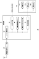
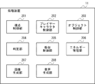
- FIG. 6 is a functional configuration diagram of the game device 10.
- the processing device 11 of the game device 10 includes a viewpoint control unit 201, a player character control unit 202, an object control unit 203, a determination unit 204, an absorption control unit 205, an energy management unit 206, an image generation unit 207, and a sound generation unit 208.
- Prepare These functional blocks can also be realized in various forms by only hardware, only software, or a combination thereof.
- the viewpoint control unit 201 controls the position of the viewpoint for generating an image of the game world.
- the viewpoint control unit 201 sets a viewpoint near the eyes of the player character and moves the position of the viewpoint as the player character moves.
- the viewpoint position is automatically set at a predetermined speed along a predetermined route in the game world. To move.
- the viewpoint control unit 201 may change the position of the viewpoint or the moving speed according to a player's instruction or a game situation, as long as it is within a predetermined range (for example, a range of a radius of several meters to several tens of meters). Good.
- a predetermined range for example, a range of a radius of several meters to several tens of meters.
- the position of the viewpoint or the moving speed may be changed within a predetermined range according to an instruction input to the input device 20 or the movement or posture of the input device 20 or the head mounted display 100.
- the movable range may be changed according to the position in the game world, the terrain, and the like. For example, the movable range may be widened in a vast grassland, or the movable range may be completely eliminated in a cave or a narrow road so that the movable range can be set only on a predetermined route.
- the viewpoint control unit 201 when the line of sight of the player character is directed toward the game object for a predetermined time or more, that is, a target such as an object or a character arranged in the game world is near the center of the display screen for a predetermined time (for example, When held for 2 to 3 seconds (also referred to as “focus”), the viewpoint position may be moved toward the target. It may be determined that the target is focused when the target is held near the center of the display screen for a predetermined time and the player extends one or both hands toward the target. In addition, the viewpoint position may stay near the target when the player character is within a predetermined range from the target or when the player character is touching the target.
- the viewpoint control unit 201 may change the viewpoint position according to an instruction from the player.
- the viewpoint position may be changed according to an instruction input to the input device 20 or the movement or posture of the input device 20 or the head mounted display 100.
- the player character control unit 202 controls the player character expressing at least a part of the player's body.
- the player character's hand and arm are moved in accordance with the movement of the input device 20.
- the player character control unit 202 may move the player character's hand and arm in accordance with the movement of a controller including a plurality of operation buttons, instead of the input device 20, or the player's hand imaged by the imaging device 14.
- the player character's hand and arm may be moved according to the movement of the arm.
- the player character control unit 202 may obtain the player's movement by capturing an image of the player wearing a suit with a marker or the like by the image capturing device 14 and analyzing the movement of the marker.
- the player may be imaged by the imaging device 14 without using the above, and the movement of the player may be acquired by any known motion capture technique.
- the head of the player character may be moved according to the movement of the head mounted display 100, or the imaging device 14 may be used. The whole body of the player character may be moved according to the movement of the body of the player who is imaged.
- the player character control unit 202 determines the display mode of the player character according to the consciousness level, the relaxation level, etc. of the player.
- the player's level of consciousness, relaxation level, etc. are stored in the energy value acquired by the player during the game, the observed values of the player's heart rate, blood pressure, body temperature, brain waves, etc., and information obtained by analyzing the captured image of the player. It may be determined based on.
- the object control unit 203 controls objects arranged in the game world.
- Objects include interactive objects that can interact with the player character and non-interactive objects that do not interact with the player character.
- An interactive object can give energy to the player character when it comes into contact with the player character. Including with non-energy objects.
- the energy object may have a shape of, for example, an animal, a plant, a crystal of quartz, or may have any shape of a sphere, a cube, a rectangular parallelepiped, a spheroid, a cone, a frustum, or the like. Good.
- the object control unit 203 automatically moves a movable object such as an animal.
- the object control unit 203 controls an object such as a plant to be shaken by the wind.
- the object control unit 203 controls an object existing in water so that the object rides on the water stream and sways.
- the object control unit 203 controls a plurality of particles forming an object so that the particles fluctuate. As a result, the mental state of the player can be relaxed.
- the object control unit 203 may move the target object toward the player character when the player focuses on the object for a predetermined time. As a result, the player can bring the object closer to and touch or resonate by gazing at the object of interest.
- the object control unit 203 determines the movement and display mode of particles that form the object according to the time the object is held near the center of the display screen, the held position, and the like. May be changed. For example, the longer an object is held near the center of the display screen, and the closer the position of the object is held to the center of the display screen is, the particles that make up the object are aggregated or displayed in a dark color. By doing so, the shape of the object may be made clear.
- the particles that make up the object are gradually diffused or displayed in a light color, so that the object melts into the space. May be given.
- the player's attention can be effectively directed to the object.
- the player is interested in surrounding objects and characters during the game play and repeats the training of paying attention to them, so that the player's concentration and attention can be improved.
- the determination unit 204 determines whether or not the player character has come into contact with the object.
- the determination unit 204 may determine that the player character has come into contact with the object when the distance between the outer surface of the player character's body and the outer surface of the object is less than a predetermined value.
- the absorption control unit 205 causes the player character to perform an action indicating that the plurality of particles included in the object that has contacted the player character is absorbed by the player character. ..
- the absorption control unit 205 may determine the action to be executed according to the type of the object with which the player character contacts. For example, when a player character comes into contact with an energetic body such as a crystal, the energetic body is thrown away by the player character or is deformed by being pushed by the player character, and then particles inside the energetic body jump out and May perform an action of moving toward the player character.
- the absorption control unit 205 exchanges the particles existing in the vicinity of the surface after the player character and the animal, the plant, etc. pass through each other and resonate with each other. You may make it perform the action mutually absorbed.
- the absorption control unit 205 may cause the sound generation unit 208 to generate and output a sound such as a binaural beat or a crystal bowl which is said to have an action of changing the brain wave.
- the player can be guided to a relaxed brain wave state, and a more comfortable feeling can be given to the player.
- the energy management unit 206 manages the amount of particles absorbed by the player character from the object as the energy acquired by the player.
- the energy management unit 206 adds energy even when the player character comes into contact with particles floating in the game world.
- the energy management unit 206 adds energy when it resonates with an object such as an animal or a plant.
- the energy management unit 206 acquires information indicating the quality of the situation in the real world from the game server 3 or the like and displays it on the game screen. When the energy acquired by the player reaches a predetermined value, the energy management unit 206 reverses the information indicating the situation in the real world. As a result, the player can enjoy not only improving the mental state of the player but also purifying the real world through the game.
- the image generation unit 207 renders a virtual three-dimensional space by using the viewpoint position set by the viewpoint control unit 201 and the line-of-sight direction set in accordance with the orientation of the head mounted display 100, thereby rendering an image of the game world. To generate.
- the image generation unit 207 changes the line-of-sight direction for generating an image in the virtual three-dimensional space according to the orientation of the head mounted display 100.
- the voice generation unit 208 generates a voice in the game world.
- the sound generation unit 208 sets a sound source to an object or particle arranged in the game world, generates a unique sound corresponding to the type of the object or particle from the sound source, and generates a sound in the game world.
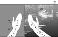
- FIG. 7 shows an example of a game screen displayed on the display device 190 of the head mounted display 100.
- a rendered image of the game world, the hand of the player character 300, and a tree 310 that is an object placed in the game world are displayed.
- Particles 303 are displayed inside the hand of the player character 300.
- the player character control unit 202 moves the position of the hand of the player character 300 according to the movement of the input device 20.
- FIG. 8 shows an example of objects arranged in the game world.
- the tree 310 shown in FIG. 8A is composed of a large number of light particles 312, as shown in an enlarged view in FIG. 8B.
- the object control unit 203 rocks the particles 312 that form the tree 310.
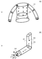
- FIG. 9 shows an example of player characters arranged in the game world.
- the shape of the player character 300 is defined by the model 301 imitating the body of the player.
- the player character 300 includes a thin gaseous base body 302 serving as a base, which is arranged in the model 301, and a large number of lights moving in and around the base body 302. It is represented by particles 303.
- a locator 304 for designating an arrangement position and a movement destination of the particles 303 is arranged.
- the player character control unit 202 slowly rocks the base body 302 on the spot, and causes the particles 303 to move back and forth inside the model 301.
- the player character control unit 202 gradually changes the display mode of the player character 300 according to the consciousness level of the player, and also changes the display mode in real time according to the player's relaxation level, actions such as breathing and purification.
- the player character control unit 202 changes the size and color of the base body 302 according to the relaxation level of the player. For example, as the player's relaxation level is higher, the base body 302 is made larger and changed to a color close to white.
- the player character control unit 202 changes the moving speed of the particles 303 according to the relaxation level of the player. For example, the higher the player's relaxation level, the slower the moving speed of the particles 303. This allows the player's relaxation level to be shown in a visually easy-to-understand manner.
- the player character control unit 202 determines the length of the lower body of the base body 302, the amount of particles 303 generated from the lower body, the intensity or color of light surrounding the base body 302, the intensity of light, or the intensity of light depending on the level of consciousness of the player. The speed at which the color changes, the type of color, etc. are changed. As a result, the player can easily objectively observe his / her own consciousness level, and when the player character of the other player is displayed on the game screen, the consciousness level of the other player can be easily grasped. You can
- the player character control unit 202 displays a state in which the player character 300 puts his / her hand on the chest while the player holds the input device 20 around his / her chest, and increases the moving speed of the particles 303, By making the light of 303 strong and changing the sound when the particles 303 flow in the body of the player character 300, the body of the player character 300 is purified, and a feeling full of energy is produced. At this time, the energy management unit 206 increases the energy of the player.
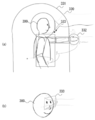
- the player character control unit 202 analyzes the image of the player captured by the image capturing device 14, and grasps the breathing motion of the player from the vertical movement of the player's shoulders and the front-back movement of the chest. While the player is inhaling, the player character control unit 202 causes particles to appear in front of the face of the player character 300 and move toward the mouth of the player character 300, as shown in FIG. Further, as shown in FIG. 10B, the model 301 of the player character 300 is inflated. At this time, as shown in FIG. 10C, since the particles 303 in the model 301 are dispersed, the density becomes low.
- the player character control unit 202 moves the particles 320 remaining in front of the face of the player character 300 away from the mouth, as shown in FIG. Further, as shown in FIG. 11B, the model 301 of the player character 300 is contracted. At this time, as shown in FIG. 11C, since the particles 303 in the model 301 aggregate, the density becomes high and the shape of the model 301 becomes clear. In this way, the player can be made aware of breathing by visualizing the action of breathing.
- FIG. 12 is a diagram for explaining the interaction between the player character and the object or particle.
- the absorption control unit 205 moves the particles 330 within the first range 331 around the player character 300 toward the player character 300.
- the first range 331 is set around the player character 300 and has a capsule-like shape. The collision determination between the first range 331 and the particles 330 and the movement to the player character 300 are not executed for the object.
- the determination unit 204 determines whether or not the particles 330 or objects arranged in the game world have come into contact with the boundary of the second range 332 around the player character 300.
- the second range 332 is narrower than the first range 331 and has a shape similar to the model of the player character 300.
- the absorption control unit 205 changes the display mode of the particle 330 or the object to a display mode indicating that the particle 330 or the object is in contact with the player character. For example, the absorption control unit 205 causes the particle 330 or the object to glow with a color according to the type of the particle 330 or the object.
- the absorption control unit 205 sets a sound source for the particles 330 within the second range 332, and causes the sound source to emit a sound according to the type of the particles 330 or the object.
- the sound source may be set to the particles 330 that are within the fourth range different from the second range 332.
- the absorption control unit 205 moves the particles 330 so as not to enter the third range 333 in front of the eyes of the player character. For example, the absorption control unit 205 moves the particles 330 that are in contact with the boundary of the third range 333 along the boundary of the third range 333. As a result, it is possible to prevent the image in which the particles hit the eyes of the player who is watching the game screen using the head mounted display 100 from being displayed.
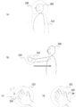
- FIG. 13 shows an example of absorption action when particles are absorbed by the player character.
- the absorption control unit 205 keeps the vector when the particles 330 move within the second range 332, as shown in FIG. It is made to enter the body of the character 300, gradually thinned to be transparent, and erased after a predetermined time.
- the absorption control unit 205 rotates the particles 330 around the hand for a predetermined time as shown in FIG. 13D. After that, as shown in FIG.
- the player character 300 is moved to the vicinity of the shoulder and further moved toward the center of the chest to be gradually thinned to be transparent and erased after a predetermined time.
- the energy management unit 206 adds the number of particles 330 absorbed by the player character 300 as the acquired energy.
- FIG. 14 shows another example of absorption action when particles are absorbed by the player character.
- the absorption control unit 205 rotates around the hand of the player character 300 as shown in FIG. 14C. While gradually decreasing the rotation speed of the particles 330, the radius of rotation is reduced to bring the particles closer to the hand, as shown in FIG. 14D, the particles are absorbed into the chest via the arms and the shoulders.
- the absorption control unit 205 may cause the particles 330 absorbed in the body of the player character 300 to exist inside the player character 300 together with the particles 303 included in the player character 300.
- the absorbed particles 330 may be displayed in a display mode different from that of the particles 303 forming the body of the player character 300.
- the image generation unit 207 does not limit the number of particles to a predetermined value. A number (for example, 10) of particles is displayed together in one particle.
- the image generation unit 207 may display the collected particles in a display mode different from that of the original particles. For example, the particle size, shape, display color, transparency, etc. may be changed.
- the image generating unit 207 collects a predetermined number of particles into one particle so that the total number of displayed particles is a predetermined number (for example, 100). If the number of particles is less than the number of particles, the total number of particles displayed may be set to a predetermined number or more by controlling the number of particles displayed collectively.
- the sound generation unit 208 combines sound sources of a predetermined number of particles into one sound source to generate sound. This makes it possible to reduce the processing load while maintaining the effect of video and audio.
- the absorption control unit 205 causes the sound generation unit 208 to generate a sound effect and a breathing sound peculiar to the object while the boundary of the second range 332 of the player character 300 touches the object, and the player touches the object through the hand.
- the character 300 is moved so that particles flow into the body of the character 300.
- the energy management unit 206 reduces the energy amount of the object while the player character 300 is absorbing energy from the object.
- the absorption control unit 205 suspends energy absorption.
- the absorption control unit 205 ends the energy absorption when the energy amount of the object becomes 0. The object whose energy amount becomes 0 cannot absorb the energy even if the player character 300 touches it again.
- the amount of energy that the object has is predetermined as a unique parameter, and basically, the player cannot absorb energy above this value from the object.
- the player can absorb more energy than the amount of energy peculiar to the object.
- the absorption control unit 205 causes the sound generation unit 208 to generate the breathing sound of the object.
- the energy management unit 206 increases the amount of energy that the object can emit. As a result, the player can be made more aware of the breathing action, and the improvement of the mental state and the health state by the correct breathing method can be promoted.
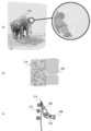
- FIG. 15 shows an example of an absorbing action when particles constituting an object are absorbed by a player character.
- an animal such as an elephant 314 arranged in the game world is also composed of a plurality of particles.
- the absorption control unit 205 causes the particle 315 forming the elephant 314 of the player character 300 to reach the elephant 314 as shown in FIG. 15C.
- the particles 315 forming the surface of the elephant 314 and the particles 303 forming the hand of the player character 300 may have different appearances. For example, as shown in FIG.
- the particles 315 forming the elephant 314 and the particles 303 forming the player character 300 may have different particle sizes, shapes, display colors, and transparency.
- the absorption control unit 205 moves the particles 316 absorbed in the body of the player character 300 toward the chest from the hand of the player character 300 via the arm. This can give the player a feeling that the energy absorbed from the elephant 314 permeates into the player's body.
- the absorption control unit 205 may move the particles 315 absorbed in the body of the player character 300 and change the appearance to the same as the particles 303 that form the player character 300. As a result, the player can feel as if the energy absorbed from the elephant 314 was converted into the player's own energy.
- the particles 315 forming the elephant 314 and the particles 303 forming the player character 300 may have the same or similar appearance. As a result, it is possible to express a world view in which all things existing in the game world are composed of the same or similar particles, and energy can be exchanged with each other. In addition, it is possible to give the player a feeling that the energy absorbed from the elephant 314 is accumulated in the player's body.
- FIG. 16 shows another example of interaction between the player character and particles.
- energy management is performed.
- the unit 206 displays energy particles 330 between both hands, and gradually increases the number of particles 330.
- the energy management unit 206 changes the display mode of the particles 330 and indicates to the player that a new object can be created, as shown in FIG.
- the energy management unit 206 changes the shape of the particle group displayed between the hands of the player character 300, as shown in FIG.
- the object 340 is formed and moved around the player character 300. As a result, the player can be motivated to accumulate a lot of energy.
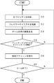
- FIG. 17 is a flowchart showing the procedure of the game control method according to the embodiment.
- the object control unit 203 controls an object that is arranged in the virtual three-dimensional space and includes a plurality of particles (S10), and the player character control unit 202 is a player that is arranged in the virtual three-dimensional space and can be operated by the player.
- the character is controlled (S12), and the image generation unit 207 generates an image of the virtual three-dimensional space (S14).
- the determination unit 204 determines whether or not the player character has come into contact with the object (S16). If there is no contact (N in S16), the process returns to S10.
- the absorption control unit 205 causes the player character to perform an action indicating that the plurality of particles included in the object in contact with the player character are absorbed by the player character (S18). If the game is not ended (N of S20), the process returns to S10, and if the game is ended (Y of S20), the process is ended.
- the present invention can be used for a display control device that controls display on a display device.
- 1 game system 3 game server, 10 game device, 11 processing device, 12 output control device, 13 storage device, 14 imaging device, 15 output device, 20 input device, 100 head mounted display, 201 viewpoint control unit, 202 player character Control unit, 203 object control unit, 204 determination unit, 205 absorption control unit, 206 energy management unit, 207 image generation unit, 208 sound generation unit.
Landscapes
- Engineering & Computer Science (AREA)
- Multimedia (AREA)
- Physics & Mathematics (AREA)
- General Physics & Mathematics (AREA)
- Theoretical Computer Science (AREA)
- Human Computer Interaction (AREA)
- Optics & Photonics (AREA)
- General Engineering & Computer Science (AREA)
- Acoustics & Sound (AREA)
- Computer Graphics (AREA)
- Computer Hardware Design (AREA)
- Software Systems (AREA)
- User Interface Of Digital Computer (AREA)
- Processing Or Creating Images (AREA)
Priority Applications (1)
| Application Number | Priority Date | Filing Date | Title |
|---|---|---|---|
| US17/292,770 US11951397B2 (en) | 2018-11-19 | 2019-11-12 | Display control program, display control device, and display control method |
Applications Claiming Priority (2)
| Application Number | Priority Date | Filing Date | Title |
|---|---|---|---|
| JP2018-216863 | 2018-11-19 | ||
| JP2018216863A JP7199204B2 (ja) | 2018-11-19 | 2018-11-19 | 表示制御プログラム、表示制御装置、及び表示制御方法 |
Publications (1)
| Publication Number | Publication Date |
|---|---|
| WO2020105503A1 true WO2020105503A1 (ja) | 2020-05-28 |
Family
ID=70774421
Family Applications (1)
| Application Number | Title | Priority Date | Filing Date |
|---|---|---|---|
| PCT/JP2019/044294 Ceased WO2020105503A1 (ja) | 2018-11-19 | 2019-11-12 | 表示制御プログラム、表示制御装置、及び表示制御方法 |
Country Status (3)
| Country | Link |
|---|---|
| US (1) | US11951397B2 (enExample) |
| JP (1) | JP7199204B2 (enExample) |
| WO (1) | WO2020105503A1 (enExample) |
Families Citing this family (4)
| Publication number | Priority date | Publication date | Assignee | Title |
|---|---|---|---|---|
| TW202231321A (zh) * | 2021-02-03 | 2022-08-16 | 宏達國際電子股份有限公司 | 追蹤系統 |
| CN113689534B (zh) * | 2021-10-25 | 2022-03-01 | 腾讯科技(深圳)有限公司 | 物理特效渲染方法、装置、计算机设备和存储介质 |
| JP7543356B2 (ja) * | 2022-09-21 | 2024-09-02 | 株式会社コロプラ | プログラムおよび情報処理システム |
| JP2024121296A (ja) * | 2023-02-27 | 2024-09-06 | 株式会社カプコン | プログラム、および音響制御装置 |
Citations (4)
| Publication number | Priority date | Publication date | Assignee | Title |
|---|---|---|---|---|
| JP2001276418A (ja) * | 2000-03-29 | 2001-10-09 | Namco Ltd | ゲーム装置、及び情報記憶媒体 |
| JP2004062676A (ja) * | 2002-07-30 | 2004-02-26 | Koei:Kk | プログラム、記録媒体、3次元群れ制御方法及びゲーム装置 |
| JP2012032951A (ja) * | 2010-07-29 | 2012-02-16 | Sony Computer Entertainment Inc | 情報処理装置および情報処理方法 |
| WO2017029915A1 (ja) * | 2015-08-17 | 2017-02-23 | 日本テレビ放送網株式会社 | プログラム、表示装置、表示方法、放送システム及び放送方法 |
Family Cites Families (4)
| Publication number | Priority date | Publication date | Assignee | Title |
|---|---|---|---|---|
| JP4307310B2 (ja) * | 2004-03-31 | 2009-08-05 | 任天堂株式会社 | ゲーム装置及びゲームプログラム |
| US10203762B2 (en) * | 2014-03-11 | 2019-02-12 | Magic Leap, Inc. | Methods and systems for creating virtual and augmented reality |
| JP6355978B2 (ja) * | 2014-06-09 | 2018-07-11 | 株式会社バンダイナムコエンターテインメント | プログラムおよび画像生成装置 |
| US10852838B2 (en) * | 2014-06-14 | 2020-12-01 | Magic Leap, Inc. | Methods and systems for creating virtual and augmented reality |
-
2018
- 2018-11-19 JP JP2018216863A patent/JP7199204B2/ja active Active
-
2019
- 2019-11-12 WO PCT/JP2019/044294 patent/WO2020105503A1/ja not_active Ceased
- 2019-11-12 US US17/292,770 patent/US11951397B2/en active Active
Patent Citations (4)
| Publication number | Priority date | Publication date | Assignee | Title |
|---|---|---|---|---|
| JP2001276418A (ja) * | 2000-03-29 | 2001-10-09 | Namco Ltd | ゲーム装置、及び情報記憶媒体 |
| JP2004062676A (ja) * | 2002-07-30 | 2004-02-26 | Koei:Kk | プログラム、記録媒体、3次元群れ制御方法及びゲーム装置 |
| JP2012032951A (ja) * | 2010-07-29 | 2012-02-16 | Sony Computer Entertainment Inc | 情報処理装置および情報処理方法 |
| WO2017029915A1 (ja) * | 2015-08-17 | 2017-02-23 | 日本テレビ放送網株式会社 | プログラム、表示装置、表示方法、放送システム及び放送方法 |
Also Published As
| Publication number | Publication date |
|---|---|
| US20210394069A1 (en) | 2021-12-23 |
| JP7199204B2 (ja) | 2023-01-05 |
| JP2020086674A (ja) | 2020-06-04 |
| US11951397B2 (en) | 2024-04-09 |
Similar Documents
| Publication | Publication Date | Title |
|---|---|---|
| JP6276882B1 (ja) | 情報処理方法、装置、および当該情報処理方法をコンピュータに実行させるためのプログラム | |
| JP6244593B1 (ja) | 情報処理方法、装置、および当該情報処理方法をコンピュータに実行させるためのプログラム | |
| JP6263252B1 (ja) | 情報処理方法、装置、および当該情報処理方法をコンピュータに実行させるためのプログラム | |
| JP6788327B2 (ja) | 表示制御プログラム、表示制御装置、及び表示制御方法 | |
| JP6290467B1 (ja) | 情報処理方法、装置、および当該情報処理方法をコンピュータに実行させるプログラム | |
| US20190073830A1 (en) | Program for providing virtual space by head mount display, method and information processing apparatus for executing the program | |
| US10545339B2 (en) | Information processing method and information processing system | |
| JP2016158795A (ja) | 表示制御プログラム、表示制御装置、及び表示制御方法 | |
| WO2020105503A1 (ja) | 表示制御プログラム、表示制御装置、及び表示制御方法 | |
| JP6321263B1 (ja) | 情報処理方法、装置、および当該情報処理方法をコンピュータに実行させるためのプログラム | |
| JP6248219B1 (ja) | 情報処理方法、コンピュータ、および当該情報処理方法をコンピュータに実行させるためのプログラム | |
| JP2019036122A (ja) | 情報処理方法、プログラム、およびコンピュータ | |
| JP2019032844A (ja) | 情報処理方法、装置、および当該情報処理方法をコンピュータに実行させるためのプログラム | |
| JP2018125003A (ja) | 情報処理方法、装置、および当該情報処理方法をコンピュータに実行させるプログラム | |
| JP6820299B2 (ja) | プログラム、情報処理装置、および方法 | |
| JP2018124981A (ja) | 情報処理方法、装置、および当該情報処理方法をコンピュータに実行させるためのプログラム | |
| JP6263292B1 (ja) | 情報処理方法、コンピュータ、および当該情報処理方法をコンピュータに実行させるためのプログラム | |
| JP2018192238A (ja) | 情報処理方法、装置、および当該情報処理方法をコンピュータに実行させるためのプログラム | |
| JP2018190196A (ja) | 情報処理方法、装置、および当該情報処理方法をコンピュータに実行させるためのプログラム | |
| JP6856572B2 (ja) | 情報処理方法、装置、および当該情報処理方法をコンピュータに実行させるためのプログラム | |
| JP2021064399A (ja) | プログラム、情報処理装置、および方法 | |
| TW201816545A (zh) | 虛擬實境頭戴式裝置 | |
| JP6330072B1 (ja) | 情報処理方法、装置、および当該情報処理方法をコンピュータに実行させるためのプログラム | |
| JP6891319B2 (ja) | 表示制御装置及び表示制御方法 | |
| JP6683862B2 (ja) | 表示制御装置及び表示制御方法 |
Legal Events
| Date | Code | Title | Description |
|---|---|---|---|
| 121 | Ep: the epo has been informed by wipo that ep was designated in this application |
Ref document number: 19886757 Country of ref document: EP Kind code of ref document: A1 |
|
| NENP | Non-entry into the national phase |
Ref country code: DE |
|
| 122 | Ep: pct application non-entry in european phase |
Ref document number: 19886757 Country of ref document: EP Kind code of ref document: A1 |