WO2020105492A1 - 磁性粒子、磁性粒子を含む磁石、磁性粒子の製造方法 - Google Patents
磁性粒子、磁性粒子を含む磁石、磁性粒子の製造方法Info
- Publication number
- WO2020105492A1 WO2020105492A1 PCT/JP2019/044140 JP2019044140W WO2020105492A1 WO 2020105492 A1 WO2020105492 A1 WO 2020105492A1 JP 2019044140 W JP2019044140 W JP 2019044140W WO 2020105492 A1 WO2020105492 A1 WO 2020105492A1
- Authority
- WO
- WIPO (PCT)
- Prior art keywords
- iron oxide
- magnetic particles
- degrees
- diffraction
- magnetic
- Prior art date
- Legal status (The legal status is an assumption and is not a legal conclusion. Google has not performed a legal analysis and makes no representation as to the accuracy of the status listed.)
- Ceased
Links
Images





Classifications
-
- B—PERFORMING OPERATIONS; TRANSPORTING
- B82—NANOTECHNOLOGY
- B82Y—SPECIFIC USES OR APPLICATIONS OF NANOSTRUCTURES; MEASUREMENT OR ANALYSIS OF NANOSTRUCTURES; MANUFACTURE OR TREATMENT OF NANOSTRUCTURES
- B82Y25/00—Nanomagnetism, e.g. magnetoimpedance, anisotropic magnetoresistance, giant magnetoresistance or tunneling magnetoresistance
-
- B—PERFORMING OPERATIONS; TRANSPORTING
- B82—NANOTECHNOLOGY
- B82Y—SPECIFIC USES OR APPLICATIONS OF NANOSTRUCTURES; MEASUREMENT OR ANALYSIS OF NANOSTRUCTURES; MANUFACTURE OR TREATMENT OF NANOSTRUCTURES
- B82Y40/00—Manufacture or treatment of nanostructures
-
- C—CHEMISTRY; METALLURGY
- C01—INORGANIC CHEMISTRY
- C01G—COMPOUNDS CONTAINING METALS NOT COVERED BY SUBCLASSES C01D OR C01F
- C01G49/00—Compounds of iron
- C01G49/02—Oxides; Hydroxides
- C01G49/06—Ferric oxide [Fe2O3]
-
- H—ELECTRICITY
- H01—ELECTRIC ELEMENTS
- H01F—MAGNETS; INDUCTANCES; TRANSFORMERS; SELECTION OF MATERIALS FOR THEIR MAGNETIC PROPERTIES
- H01F1/00—Magnets or magnetic bodies characterised by the magnetic materials therefor; Selection of materials for their magnetic properties
- H01F1/01—Magnets or magnetic bodies characterised by the magnetic materials therefor; Selection of materials for their magnetic properties of inorganic materials
- H01F1/03—Magnets or magnetic bodies characterised by the magnetic materials therefor; Selection of materials for their magnetic properties of inorganic materials characterised by their coercivity
- H01F1/032—Magnets or magnetic bodies characterised by the magnetic materials therefor; Selection of materials for their magnetic properties of inorganic materials characterised by their coercivity of hard-magnetic materials
- H01F1/10—Magnets or magnetic bodies characterised by the magnetic materials therefor; Selection of materials for their magnetic properties of inorganic materials characterised by their coercivity of hard-magnetic materials non-metallic substances, e.g. ferrites, e.g. [(Ba,Sr)O(Fe2O3)6] ferrites with hexagonal structure
- H01F1/11—Magnets or magnetic bodies characterised by the magnetic materials therefor; Selection of materials for their magnetic properties of inorganic materials characterised by their coercivity of hard-magnetic materials non-metallic substances, e.g. ferrites, e.g. [(Ba,Sr)O(Fe2O3)6] ferrites with hexagonal structure in the form of particles
-
- H—ELECTRICITY
- H01—ELECTRIC ELEMENTS
- H01F—MAGNETS; INDUCTANCES; TRANSFORMERS; SELECTION OF MATERIALS FOR THEIR MAGNETIC PROPERTIES
- H01F41/00—Apparatus or processes specially adapted for manufacturing or assembling magnets, inductances or transformers; Apparatus or processes specially adapted for manufacturing materials characterised by their magnetic properties
- H01F41/02—Apparatus or processes specially adapted for manufacturing or assembling magnets, inductances or transformers; Apparatus or processes specially adapted for manufacturing materials characterised by their magnetic properties for manufacturing cores, coils, or magnets
Definitions
- the present invention relates to magnetic particles, a magnet containing magnetic particles, and a method for producing magnetic particles.
- Neodymium magnets are known as magnets having a large residual magnetic flux density (residual magnetization) Br and a large coercive force Hc.
- residual magnetization residual magnetization
- Hc coercive force
- a magnetic material containing ⁇ -iron oxide in fine particles is known as a magnetic material that is stable in price and supply and has excellent magnetic properties.
- Japanese Patent Laid-Open No. 2008-174405 discloses a magnetic fine particle containing single-phase ⁇ -iron oxide in which heterophasic components such as ⁇ -iron oxide and ⁇ -iron oxide are reduced by substituting a part of iron in ⁇ -iron oxide with a metal. It is disclosed to synthesize sex.
- Japanese Patent Laid-Open No. 2014-224027 discloses that the average particle size of the magnetic particles is set to 15 nm or less without using a substitutional metal so as to obtain a single phase.
- Japanese Unexamined Patent Application Publication No. 2014-224027 discloses that the residual magnetic flux density and the coercive force are based on the recognition that ⁇ -iron oxide and ⁇ -iron oxide cause a decrease in the coercive force and the remanent magnetization expressed by the ⁇ -iron oxide phase. At a level that did not decrease, heterophasic precipitation of ⁇ -iron oxide and ⁇ -iron oxide was suppressed, and ⁇ -iron oxide was synthesized as a dominant.
- An object of the present invention is to stably provide magnetic particles containing ⁇ iron oxide having excellent magnetic properties.
- the magnetic particles according to the first of the present invention are magnetic particles containing iron oxide,
- diffraction angles of 58.8 degrees or more and 64.8 degrees or less
- diffraction intensity is exhibited on each of the low angle side and the high angle side of 61.8 degrees
- the diffraction angle width ⁇ 2 ⁇ (L) of the diffraction intensity on the lower angle side than 61.8 degrees is narrower than the diffraction angle width ⁇ 2 ⁇ (H) of the diffraction intensity on the higher angle side than 61.8 degrees.
- an equimolar amount or less of ammonia is added to an iron nitrate aqueous solution in which iron (III) nitrate nonahydrate is dissolved to prepare an iron oxide hydroxide dispersion solution.
- 3 shows an X-ray diffraction profile of magnetic particles according to the first embodiment.
- 1 illustrates a method for identifying a diffraction angle width of magnetic particles according to a first embodiment.
- 3 is a diagram showing a specified diffraction angle width of the magnetic particles according to the first embodiment.
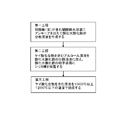
- 3 is a flowchart showing a method of manufacturing magnetic particles according to the first embodiment.
- 3 shows a scanning electron microscope image of magnetic particles according to the first example.
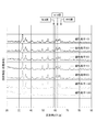
- 3 is an X-ray diffraction profile of magnetic particles according to Examples 1 to 5 and Comparative Examples 1 and 2.
- FIG. 7 is a graph showing the relationship between the magnetic properties of magnetic particles according to Examples 1 to 5 and Comparative Examples 1 and 2 and the normalized diffraction angle width ⁇ 2 ⁇ (L) / ⁇ 2 ⁇ (H). It shows an X-ray diffraction profile exhibited by ⁇ -iron oxide and ⁇ -iron oxide.
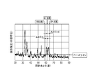
- FIG. 1A shows an X-ray diffraction profile obtained by measuring the magnetic particles according to the first embodiment by the 2 ⁇ method.
- the magnetic particles of this embodiment contain at least ⁇ -iron oxide, ⁇ -iron oxide, and ⁇ -iron oxide as allotropes of iron oxide having different crystal structures.
- Heterogeneous phase (sometimes referred to as mixed crystal)
- ⁇ iron oxide is contained as a main phase
- at least one of ⁇ iron oxide and ⁇ iron oxide is contained as a trace phase.
- the inventors of the present application rather than limiting the precipitation of ⁇ -iron oxide, ⁇ -iron oxide, in the heterophasic morphology other than ⁇ iron oxide at a relatively predetermined concentration, by taking a specific heterophasic morphology, rather, retention It was found that magnetic particles having high force Hc and high residual magnetization Br can be stably produced.
- the aspect of the different phase of this embodiment is specified by X-ray diffraction.
- FIG. 1A is an X-ray diffraction profile of the magnetic particle 10 of the first embodiment measured by the 2 ⁇ method, and shows a broad diffraction intensity specifically around a diffraction angle 2 ⁇ of 60 degrees. It can be said that a table-like diffraction intensity band is exhibited around a diffraction angle 2 ⁇ of 60 degrees.
- the diffraction angle width ⁇ 2 ⁇ (H) of the diffraction intensity on the higher angle side than 61.8 degrees is wider than the diffraction angle width ⁇ 2 ⁇ (L) of the diffraction intensity on the lower angle side than 61.8 degrees. Is present.
- the diffraction angle width ⁇ 2 ⁇ (H) corresponding to the diffraction peak angle of 61.8 degrees or more and less than 64.8 degrees is the diffraction angle width of the diffraction peak angle of 58.8 degrees or more and less than 61.8 degrees. It can be read that it is wider than ⁇ 2 ⁇ (L).
- the diffraction angle widths ⁇ 2 ⁇ (L) and ⁇ 2 ⁇ (H) are uniquely specified by steps 1 to 3 shown in FIG. 1B.
- Procedure 1) Baseline is the intersection point where the diffraction angle 2 ⁇ is 61.8 degrees.
- the X-ray diffraction profile of the magnetic fine particles 10 of this embodiment is characterized as shown in FIG. 1C.
- the inventors of the present application found that the broad diffraction intensities recognized at diffraction angles of 58.8 degrees to 64.8 degrees were four diffraction angles of 60.9 degrees, 62.3 degrees, 63.2 degrees, and 63.9 degrees. It was found that it is composed of at least three peaks.
- the above-mentioned three diffraction peaks are one diffraction peak (60.9 degrees) present at 58.8 degrees or more and less than 61.8 degrees and two diffraction peaks (62 degrees above 62 degrees and less than 64.8 degrees). 3 degrees, 63.2 degrees, and 63.9 degrees).
- FIG. 4 shows X-ray diffraction profiles of single-phase ⁇ -iron oxide and ⁇ -iron oxide, respectively. It can be read that near the diffraction angle of 60 degrees, the X-ray diffraction profile of the present embodiment shown in FIG. 1A is clearly different from the X-ray diffraction profiles corresponding to ⁇ iron oxide and ⁇ iron oxide shown in FIG. ..
- the magnetic particle 10 of the present embodiment has excellent magnetic characteristics even though it contains a hetero phase, and the magnetic characteristics are those of the conventional technology including a single phase ⁇ iron oxide, ⁇ iron oxide, and a different phase (Comparative Examples 1 and 2 described later). ) Is superior to any of the above.
- the crystal structural characteristics of the magnetic particles 10 of the present embodiment are determined by X-ray diffraction. I came to think that the profile supports the profile.
- the particles evaluated and analyzed by X-ray diffraction contain ⁇ iron oxide in a larger molar ratio than ⁇ iron oxide and ⁇ iron oxide. Further, it is understood that the ⁇ iron oxide contained in the particles evaluated and analyzed by X-ray diffraction contains the metal element M substituting for iron. In addition, the ⁇ iron oxide contained in the particles evaluated and analyzed by X-ray diffraction is said to be contained in the form of ⁇ -MxFe (2-x) O 3 .
- M is a metal substituting iron having a valence of 3
- x is a number of 0 or more and less than 2. The number x is preferably 0.10 or less, more preferably 0.05 or less.
- an iron nitrate aqueous solution prepared by dissolving iron nitrate (III) nonahydrate in water is prepared.
- ammonia water is added to the iron nitrate aqueous solution in an amount equal to or less than equimolar.
- the addition amount of the ammonia water is an addition amount for maintaining the pH of the iron nitrate aqueous solution at 3 or less.
- the surface of iron oxide hydroxide particles is coated with silicon oxide (silica).
- silicon oxide silicon oxide
- an alcohol solution in which ethyl silicate is dissolved as a silicate compound is added to the iron oxide hydroxide dispersion solution.
- ethyl silicate is quickly and uniformly coated on the surface of the iron oxide hydroxide particles.
- methanol, butanol, octanol, or ethanol is appropriately adopted.
- the molar ratio of the silicon ion component ratio of ethyl silicate to the iron ion component of iron nitrate is preferably 0.1 times or more, more preferably 0.5 to 10 times.
- ethyl silicate is further added and stirred for 8 to 16 hours to coat the surface of the iron oxide hydroxide particles with a uniform silica film.
- iron oxide hydroxide can be produced by a simpler method as compared with the conventional manufacturing method which conventionally required a step of combining the reverse micelle method and the sol-gel method. It has become possible to perform silica coating treatment on the surface of particles.
- particle powder is obtained from a dispersion solution of iron oxide hydroxide particles covered with a silica film.
- this step appropriately includes sub-steps of separating, washing and drying.
- the obtained particle powder is placed inside a firing furnace and fired at a temperature of 1000 ° C. or higher and 1200 ° C. or lower in an air or nitrogen atmosphere.
- ⁇ iron oxide particles having changed iron hydroxide particles can be obtained.
- the firing temperature in this step it is preferable to select a temperature determined according to the content of ethyl silicate, that is, the Si / Fe molar ratio.
- the firing temperature in the third step is adjusted according to the molar ratio of silicon to iron in the dispersion solution of iron oxide hydroxide in the second step. In other words. In other words, the firing temperature in the third step is adjusted to a higher firing temperature as the molar ratio of silicon to iron in the iron oxide hydroxide dispersion solution in the second step increases.
- the third step includes a sub-step in which the magnetic powder after the heat treatment is put into an alkaline aqueous solution in which a strong alkali such as sodium hydroxide or potassium hydroxide is dissolved and the mixture is stirred.
- a strong alkali such as sodium hydroxide or potassium hydroxide
- the silica compound coated on the surface of the ⁇ iron oxide particles is removed. It is possible to add sodium hydroxide in a molar ratio of 4 to 6 times that of silica.
- the median particle size distribution has a uniform particle size of 15 nm or more and 35 nm or less, and ⁇ iron oxide and ⁇ iron oxide are contained as the main phase. Magnetic particles having a hetero-phase structure containing are obtained.
- the magnetic particles of the first embodiment are limited in utility in various applications including electromagnetic motor applications utilizing Lorentz force, magnetic recording applications, and electromagnetic wave shielding applications. If necessary, such a magnetic particle can be supported on a carrier in a range that does not cancel out the magnetic characteristics of the magnetic particle, so that the magnet 100 and the electromagnetic wave shield suitable for the intended use can be formed. In this specification, this is referred to as a third embodiment.
- FIG. 2 is a flowchart showing a method of manufacturing magnetic particles according to Examples 1 to 5 corresponding to the first embodiment.
- Example 1 As a first step, iron nitrate hydrate (Fe (NO 3) 3 ⁇ 9H 2 O) 12.12g of pure water 50 g, and a magnetic stirrer was placed in a beaker, and stirred for 30 minutes at a rotation speed 300rpm . Next, 1.8 g of 28% wt ammonia water was diluted in 18 g of pure water and added dropwise to the above beaker so that the addition was completed in 200 seconds.
- Fe (NO 3) 3 ⁇ 9H 2 O iron nitrate hydrate
- the silica-coated iron oxide hydroxide dispersion solution was washed with pure water and dried, and then baked in an electric furnace at 1000 ° C for 4 hours.
- the obtained ⁇ -iron oxide magnetic powder whose particle surface was coated with silica was stirred for 4 hours in 150 g of a 20% aqueous sodium hydroxide solution heated to 95 ° C. to remove the silica coating, and then pure water was added.
- the resultant was washed with and dried to obtain magnetic particles 10 of ⁇ iron oxide.
- Iron nitrate hydrate (Fe (NO 3) 3 ⁇ 9H 2 O) was added to 12.12g of pure water 50g in 600ml beaker containing rotor is stirred for 30 minutes rotating with a magnetic stirrer 300 rpm.
- 1.8 g of 28% ammonia water was diluted in 18 g of pure water and added dropwise to the above beaker so that the addition was completed in 200 seconds, and then the dispersion solution was continuously stirred for 30 minutes and left standing for 1 hour without stirring. At that time, the sedimentation property of the dispersed solution was visually evaluated. Even after 1 hour, no sedimentation of particles in the dispersion solution was observed, and it was confirmed that the dispersion stability was good.
- the magnetic particles 10 obtained through the third step were analyzed by the X-ray diffraction method.
- the obtained X-ray diffraction profile of the 2 ⁇ method is, as shown in the first view from the top of FIGS. 1 and 4, an angle lower than 61.8 ° at a diffraction angle 2 ⁇ of 58.8 ° or more and 64.8 ° or less.
- the diffraction intensity was exhibited on each of the side and the high angle side.
- the obtained X-ray diffraction profile of the 2 ⁇ method shows that the diffraction angle width ⁇ 2 ⁇ (L) of the diffraction intensity on the lower angle side than 61.8 degrees is 2.20 degrees, which is on the higher angle side than 61.8 degrees.
- the diffraction angle width ⁇ 2 ⁇ (H) of the diffraction intensity was 2.58 degrees. That is, the normalized diffraction angle width ratio ⁇ 2 ⁇ (L) / ⁇ 2 ⁇ (H) of the magnetic particles 10 of this example was 0.87.
- FIG. 5 shows the relationship between the diffraction angle width ratio ⁇ 2 ⁇ (L) / ⁇ 2 ⁇ (H) of the magnetic particles 10 according to Examples 1 to 5 and Comparative Examples 1 and 2 and the magnetic characteristics (residual magnetization Br and coercive force Hc). It is a plot.
- Example 2 Magnetic particles 20 were obtained in the same manner as in Example 1 except that the amount of ethyl silicate added in the second step was 7.56 g and the firing temperature in the third step was 1050 ° C.
- the magnetic particles 20 obtained through the third step were analyzed by the X-ray diffraction method.
- the X-ray diffraction profile of the obtained 2 ⁇ method is, as shown in the second from the top of FIG. Diffraction intensity was exhibited on each side. Further, the obtained X-ray diffraction profile of the 2 ⁇ method shows that the diffraction angle width ⁇ 2 ⁇ (L) of the diffraction intensity on the lower angle side than 61.8 degrees is 1.80 degrees, which is on the higher angle side than 61.8 degrees.
- the diffraction angle width ⁇ 2 ⁇ (H) of the diffraction intensity was 2.60 degrees. That is, the normalized diffraction angle width ratio ⁇ 2 ⁇ (L) / ⁇ 2 ⁇ (H) of the magnetic particles 20 of the present example was 0.69.
- the average particle diameter of the magnetic particles 20 according to this example by a scanning microscope was 20 nm, and the standard deviation was 4 nm.
- Example 3 Magnetic particles 30 were obtained in the same manner as in Example 1 except that the amount of ethyl silicate added in the second step was 25.2 g and the firing temperature in the third step was 1150 ° C.
- the magnetic particles 30 obtained through the third step were analyzed by the X-ray diffraction method.
- the obtained X-ray diffraction profile of the 2 ⁇ method is, as shown in the third from the top of FIG. 4, at a diffraction angle 2 ⁇ of 58.8 ° or more and 64.8 ° or less, a lower angle side and a higher angle than 61.8 °
- the diffraction intensity was exhibited on each of the side and the side.
- the obtained X-ray diffraction profile of the 2 ⁇ method shows that the diffraction angle width ⁇ 2 ⁇ (L) of the diffraction intensity on the lower angle side than 61.8 degrees is 2.00 degrees, which is on the higher angle side than 61.8 degrees.
- the diffraction angle width ⁇ 2 ⁇ (H) of the diffraction intensity was 2.60 degrees. That is, the normalized diffraction angle width ratio ⁇ 2 ⁇ (L) / ⁇ 2 ⁇ (H) of the magnetic particles 30 of the present example was 0.77.
- the average particle size was 25 nm and the standard deviation was 10 nm.
- Example 4 Magnetic particles 40 were obtained in the same manner as in Example 1 except that the amount of ethyl silicate added in the second step was 50.4 g and the firing temperature in the third step was 1180 ° C.
- the magnetic particles 40 obtained through the third step were analyzed by the X-ray diffraction method.
- the obtained X-ray diffraction profile of the 2 ⁇ method is, as shown in the fourth from the top of FIG. 4, at a diffraction angle 2 ⁇ of 58.8 ° or more and 64.8 ° or less, a lower angle side than 61.8 ° Diffraction intensity was exhibited on each side.
- the obtained X-ray diffraction profile of the 2 ⁇ method shows that the diffraction angle width ⁇ 2 ⁇ (L) of the diffraction intensity on the lower angle side than 61.8 degrees is 2.13 degrees, which is on the higher angle side than 61.8 degrees.
- the diffraction angle width ⁇ 2 ⁇ (H) of the diffraction intensity was 2.47 degrees. That is, the normalized diffraction angle width ratio ⁇ 2 ⁇ (L) / ⁇ 2 ⁇ (H) of the magnetic particles 40 of the present example was 0.86.
- the average particle size was 22 nm and the standard deviation was 6 nm.
- Example 5 Magnetic particles 50 were obtained in the same manner as in Example 1 except that the amount of ethyl silicate added in the second step was 75.6 g and the firing temperature in the third step was 1200 ° C.
- the magnetic particles 50 obtained through the third step were analyzed by the X-ray diffraction method.
- the obtained X-ray diffraction profile of the 2 ⁇ method is as shown in the fifth from the top of FIG. Diffraction intensity was exhibited on each side. Further, the obtained X-ray diffraction profile of the 2 ⁇ method shows that the diffraction angle width ⁇ 2 ⁇ (L) of the diffraction intensity on the lower angle side than 61.8 degrees is 2.13 degrees, which is on the higher angle side than 61.8 degrees.
- the diffraction angle width ⁇ 2 ⁇ (H) of the diffraction intensity was 2.53 degrees. That is, the normalized diffraction angle width ratio ⁇ 2 ⁇ (L) / ⁇ 2 ⁇ (H) of the magnetic particles 50 of this example was 0.84.
- the average particle size was 28 nm and the standard deviation was 4 nm.
- Magnetic particles 110 of this comparative example were obtained in the same manner as in Example 1 except that the firing temperature in the third step was 1180 ° C.
- the magnetic particles 110 obtained through the third step were analyzed by the X-ray diffraction method.
- the obtained X-ray diffraction profile of the 2 ⁇ method is, as shown in the sixth from the top of FIG. 4, a diffraction intensity on the higher angle side than 61.8 degrees at a diffraction angle 2 ⁇ of 58.8 degrees to 64.8 degrees. However, no significant diffraction intensity was exhibited on the lower angle side than 61.8 degrees.
- the obtained X-ray diffraction profile of the 2 ⁇ method shows that the diffraction angle width ⁇ 2 ⁇ (L) of the diffraction intensity on the lower angle side than 61.8 degrees is 0 degree, and the diffraction angle on the higher angle side than 61.8 degrees.
- the intensity diffraction angle width ⁇ 2 ⁇ (H) was 1.80 degrees. That is, the normalized diffraction angle width ratio ⁇ 2 ⁇ (L) / ⁇ 2 ⁇ (H) of the magnetic particles 110 of this comparative example was 0.
- the average particle size was 30 nm and the standard deviation was 10 nm.
- Magnetic particles 120 of this comparative example were obtained in the same manner as in Example 4 except that the firing temperature in the third step was 1050 ° C.
- the magnetic particles 120 obtained through the third step were analyzed by the X-ray diffraction method.
- the X-ray diffraction profile of the obtained 2 ⁇ method is as shown in the seventh from the top of FIG. Diffraction intensity was exhibited on each side. Further, the obtained X-ray diffraction profile of the 2 ⁇ method shows that the diffraction angle width ⁇ 2 ⁇ (L) of the diffraction intensity on the lower angle side than 61.8 degrees is 2.33 degrees, which is on the higher angle side than 61.8 degrees.
- the diffraction angle width ⁇ 2 ⁇ (H) of the diffraction intensity was 2.20 degrees. That is, the normalized diffraction angle width ratio ⁇ 2 ⁇ (L) / ⁇ 2 ⁇ (H) of the magnetic particles 120 of this comparative example was 1.06.
- the average particle size was 20 nm and the standard deviation was 8 nm.
- the magnetic characteristics are high in the aspect (corresponding to Examples 1 to 5) that satisfies the predetermined diffraction angle width ratio ⁇ 2 ⁇ (L) / ⁇ 2 ⁇ (H).
- the diffraction angle width ratio ⁇ 2 ⁇ (L) / ⁇ 2 ⁇ (H) is the diffraction width ⁇ 2 ⁇ (L) on the low angle side divided by the diffraction width ⁇ 2 ⁇ (H) on the high angle side.
- the predetermined diffraction angle width ratio ⁇ 2 ⁇ (L) / ⁇ 2 ⁇ (H) satisfies the following general formula (1), it is a heterogeneous magnetic particle containing ⁇ iron oxide or ⁇ iron oxide in the main phase of ⁇ iron oxide.
- the present inventors have found that they also have high magnetic properties. 0.50 ⁇ ⁇ 2 ⁇ (L) / ⁇ 2 ⁇ (H) ⁇ 0.95 (Equation 1)
- both the residual magnetization Br and the coercive force Hc have high values, which is preferable. 0.69 ⁇ ⁇ 2 ⁇ (L) / ⁇ 2 ⁇ (H) ⁇ 0.87 (Formula 2)
- the particle size, magnetic properties, and X-ray diffraction method described in this specification are evaluated at room temperature of 20 ° C.
Landscapes
- Engineering & Computer Science (AREA)
- Chemical & Material Sciences (AREA)
- Nanotechnology (AREA)
- Power Engineering (AREA)
- Organic Chemistry (AREA)
- Manufacturing & Machinery (AREA)
- Crystallography & Structural Chemistry (AREA)
- Physics & Mathematics (AREA)
- General Physics & Mathematics (AREA)
- Inorganic Chemistry (AREA)
- Condensed Matter Physics & Semiconductors (AREA)
- Hard Magnetic Materials (AREA)
- Manufacturing Cores, Coils, And Magnets (AREA)
- Compounds Of Iron (AREA)
Abstract
置換金属を導入せずに、簡便な製造方法でε酸化鉄を主相としα酸化鉄とγ酸化鉄を副成分として含有する異相構造を持つ酸化鉄ナノ磁性粒子粉を製造する手段を提供する。
Description
本発明は、磁性粒子、磁性粒子を含む磁石、磁性粒子の製造方法に関する。
残留磁束密度(残留磁化)Brおよび保磁力Hcがともに大きい磁石として、ネオジム磁石が知られている。ネオジム磁石は、ネオジム磁石は、地球上に偏在する希土類元素であるネオジムを含有しているため、価格と供給の安定化について懸念されている。希土類元素フリーまたは含有量が低減されたネオジウム磁石を代替する磁性材料が求められている。
価格と供給の安定化が担保され磁気特性が優れた磁性材料として、ε酸化鉄を微粒子中に含有する磁性体が知られている。特開2008-174405号公報は、ε酸化鉄中の鉄の一部を金属で置換することにより、α酸化鉄やγ酸化鉄等の異相成分を低減した単相のε酸化鉄を含む磁性微粒性を合成することが開示されている。
また、特開2014-224027号公報は、置換金属を用いることなく、磁性粒子の平均粒径を15nm以下とすることにより、単相化することを開示している。特開2014-224027号公報は、γ酸化鉄、α酸化鉄は、それぞれ、ε酸化鉄相が発現する保磁力、残留磁化の低下をもたらすとの課題認識に基づき、残留磁束密度や保磁力が低下しない水準でα酸化鉄やγ酸化鉄等の異相析出を抑制し、ε酸化鉄をドミナントとして合成していた。
特開2014-224027号公報の手法では、ε酸化鉄の含有量の高い割に所望の磁気特性が得られない場合おそれがあった。ε酸化鉄粒子の分級性能に対してロバストな方法で、磁気特性に優れたε酸化鉄を含む磁性粒子を安定して提供することが求められていた。
本発明は、このような課題認識に基づいてなされたものである。本発明の目的は、磁気特性に優れたε酸化鉄を含む磁性粒子を安定して提供することである。
本発明の第一に係る磁性粒子は酸化鉄を含有する磁性粒子であって、
2θ法によるX線回折法において、58.8度以上64.8度以下の回折角において、61.8度より低角側と高角側とのそれぞれにおいて回折強度を呈し、
61.8度より低角側の回折強度の回折角幅Δ2θ(L)は、61.8度より高角側の回折強度の回折角幅Δ2θ(H)より狭いことを特徴とする。
2θ法によるX線回折法において、58.8度以上64.8度以下の回折角において、61.8度より低角側と高角側とのそれぞれにおいて回折強度を呈し、
61.8度より低角側の回折強度の回折角幅Δ2θ(L)は、61.8度より高角側の回折強度の回折角幅Δ2θ(H)より狭いことを特徴とする。
また、本発明の第二に係る磁性粒子の製造方法は、硝酸鉄(III)9水和物を溶解させた硝酸鉄水溶液に、等モル以下のアンモニアを加えて酸化水酸化鉄分散溶液を作成する第一工程と、ケイ酸化合物を溶解する溶媒を前記酸化水酸化鉄分散溶液に追加しケイ酸化合物溶解液を作成する第二工程と、を有することを特徴とする。
以下、本発明の実施の形態について説明する。なお、本発明は、以下の実施の形態に限定されるものではなく、本発明の趣旨を逸脱しない範囲で、当業者の通常の知識に基づいて、以下の実施の形態に対して適宜変更、改良等が加えられたものも本発明の範囲に含まれる。
<第一の実施形態>
図1Aは、第一の実施形態に係る磁性粒子を2θ法で測定したX線回折プロファイルを示すものである。
図1Aは、第一の実施形態に係る磁性粒子を2θ法で測定したX線回折プロファイルを示すものである。
本実施形態の磁性粒子は、互いに異なる結晶構造をとる酸化鉄の同素体として、少なくとも、α酸化鉄、γ酸化鉄、ε酸化鉄を含有する。異相(混晶と言い換えることもある)、ε酸化鉄を主相として含有し、微量相として、α酸化鉄とγ酸化鉄の少なくともいずれかを含む。
本願の発明者等は、α酸化鉄、γ酸化鉄の析出を制限するよりも、相対的に所定濃度でε酸化鉄以外を含む異相形態において、特定の異相形態をとることにより、却って、保持力Hcと残留磁化Brが高い磁性粒子を安定的に作成できることを見出した。本実施形態の異相の態様は、X線回折により特定される。
図1Aは、2θ法により測定した第一の実施形態の磁性粒子10のX線回折プロファイルであって、回折角2θが60度周辺にブロードな回折強度を特異的に呈している。回折角2θが60度周辺に、テーブル状の回折強度バンドを呈しているとも換言できる。
本実施形態のX線回折プロファイルからは、58.8度以上64.8度以下の回折角において、61.8度より低角側と高角側とのそれぞれにおいて回折ピークを呈していることが読み取られる。さらに、かかるX線回折プロファイルは、61.8度より高角側の回折強度の回折角幅Δ2θ(H)は、61.8度より低角側の回折強度の回折角幅Δ2θ(L)より広いことを呈している。すなわち、61.8度以上64.8度未満に呈する回折ピーク角に対応する回折角幅Δ2θ(H)は、58.8度以上61.8度未満に呈する回折ピーク角に対応する回折角幅Δ2θ(L)より広いことが読み取られる。
なお、回折角幅Δ2θ(L)、Δ2θ(H)は、図1Bに記載の手順1~3により、それぞれ、一義的に特定される。手順1)回折角2θが61.8度の交点をベースラインとする。手順2)回折角2θが61.8度より低角側において、ベースラインより強度が高い回折強度に対応する回折角の範囲を低角側回折幅Δ2θ(L)とする。手順3)回折角2θが61.8度より高角側において、ベースラインより強度が高い回折強度に対応する回折角の範囲を高角側回折幅Δ2θ(H)とする。
このようにして、本実施形態の磁性微粒子10のX線回折プロファイルは、図1Cに示すように特徴づけられる。
本願発明者等は、回折角が58.8度~64.8度に認められるブロードな回折強度は、60.9度、62.3度、63.2度、63.9度の4つの回折ピークの少なくとも3つ以上から構成されていることを見出した。前述の3つの回折ピークは、58.8度以上61.8度未満に呈する1つの回折ピーク(60.9度)と、61.8度以上64.8度未満に呈する2つの回折ピーク(62.3度、63.2度、63.9度のうちの2つ)と、に対応する。
図4は、単相のα酸化鉄、γ酸化鉄が示すX線回折プロファイルをそれぞれ示すものである。回折角60度付近において、図1Aに示す本実施形態のX線回折プロファイルは、図4に示されるα酸化鉄、γ酸化鉄に対応するX線回折プロファイルとは明らかに異なっていること読み取られる。本実施形態の磁性粒子10は、異相を含むものの優れた磁気特性を有し、その磁気特性は、単相のα酸化鉄、γ酸化鉄、異相を含む従来技術(後述する比較例1及び2)のいずれよりも優れていることを見出した。本願発明者等は、さらに、かかる本実施形態の磁気特性を発現する機序に関する結晶工学的な解は得られていないものの、本実施形態の磁性粒子10の結晶構造的な特徴をX線回折プロファイルが裏付けるものであると思料するに至った。
本実施形態に記載のX線回折プロファイルは、X線回折で評価解析した粒子は、モル比において、ε酸化鉄が、α酸化鉄および前記γ酸化鉄より多く含有されていると理解される。また、X線回折で評価解析した粒子に含有されるε酸化鉄は、鉄を置換する金属元素Mを含むと理解される。また、X線回折で評価解析した粒子に含有されるε酸化鉄は、ε―MxFe(2-x)O3、の形式で含有されていると換言される。但し、Mは価数3をとる鉄を置換する金属であり、xは0以上2未満の数である。なお、数xは、0.10以下であることが好ましく、0.05以下であることがさらに好ましい。
<第二の実施形態>
次に、第一の実施形態に係る磁性粒子10の製造方法に係る第二の実施形態を図2を用いて説明する。
次に、第一の実施形態に係る磁性粒子10の製造方法に係る第二の実施形態を図2を用いて説明する。
第一の工程では硝酸鉄(III)9水和物を水に溶解させた硝酸鉄水溶液を用意する。次に、かかる硝酸鉄水溶液に対し、アンモニア水を等モル以下の量を加える。本工程において、アンモニア水の添加量は、硝酸鉄水溶液のPHを3以下に維持するための添加量である。このPH上限を満足することにより、硝酸鉄微粒子を抑制し平均粒径5nm程度の球状の酸化水酸化鉄が分散した酸化水酸化鉄粒子の分散溶液を得る。
次に、第二の工程では酸化水酸化鉄粒子の表面に酸化ケイ素(シリカ)を被覆する工程である。本工程では、酸化水酸化鉄粒子の表面のシリカ膜を均一化するために、ケイ酸化合物としてケイ酸エチルが溶解するアルコール溶液を、酸化水酸化鉄の分散溶液に加える。かかるアルコールの添加により、ケイ酸エチルが素早く、均一に酸化水酸化鉄粒子の表面に被覆される。添加されるアルコールは、メタノール、ブタノール、オクタノール、エタノールが、適宜、採用される。硝酸鉄の鉄イオン成分に対してケイ酸エチルのケイ素イオン成分比(Si/Fe比)が、モル比において、0.1倍以上であることが好ましく、さらに好ましくは0.5~10倍とすることが好ましい。本工程において、さらに、ケイ酸エチルを加え、8時間から16時間撹拌を行い酸化水酸化鉄粒子の表面に均一なシリカ膜を被覆する。
第一、第二の工程を採用することにより、従来、逆ミセル法とゾル-ゲル法を組み合わせた工程が必要であった従来の製造方法に比較して、より簡易な方法で酸化水酸化鉄の粒子表面にシリカコーティング処理を行うことが可能となった。
次に、第三の工程として、シリカ膜が被覆された酸化水酸化鉄粒子を分散溶液から粒子粉体を得る。かかる分散溶液から粒子紛体を得るために、本工程は、分離・洗浄・乾燥を行う各サブ工程が適宜含まれる。得られた粒子粉体を焼成炉の内部に配置し、空気または窒素雰囲気中で1000℃以上1200℃以下の温度で焼成する。この工程により、水酸化鉄粒子が変化したε酸化鉄粒子が得られる。本工程の焼成温度は、ケイ酸エチルの含有量、すなわちSi/Feのモル比に応じて決定される温度を選択することが好ましい。
本工程において、シリカ含有量に応じて選択した焼成(熱処理)を行うことで、一次粒子の粒度が整った均一なε酸化鉄粒子が得られる。シリカ含有量を考慮せずに1000℃以上1200℃以下の温度で焼成した場合に比較して、残留磁化Brや保持力Hcの低下が軽減される。(後述する比較例1、2に対応)従って、第三工程における焼成温度は、第二の工程における酸化水酸化鉄の分散溶液中の鉄に対するケイ素のモル比に応じて調整されたものであると換言される。また、第三工程における焼成温度は、第二の工程における酸化水酸化鉄の分散溶液中の鉄に対するケイ素のモル比が大きいほど高い焼成温度に調整されたものであると換言される。
本第三工程は、水酸化ナトリウム、水酸化カリウムなどの強アルカリを溶解させたアルカリ水溶液に、熱処理後の磁性粉末を入れて撹拌するサブ工程を含む。かかるサブ工程を行うことにより、ε酸化鉄粒子の表面に被覆されたシリカ化合物が除去される。水酸化ナトリウムをシリカに対してモル比で4倍から6倍の範囲で添加することが可能である。
前述のアルカリ水溶液の加熱し95℃の状態で磁性粉末を入れ数時間撹拌する。シリカ膜をアルカリ水溶液に溶解させシリカ被覆が除去される。かかる水溶液を冷却後、洗浄、乾燥することで目的とするε酸化鉄主相の磁性粒子10を得ることができる。
本実施形態に適用した、磁性粒子の製造方法によれば、粒度分布の中央値が15nm以上35nm以下と粒径が揃い、かつ、α酸化鉄、γ酸化鉄を含みε酸化鉄を主相として含む異相構造の磁性粒子が得られる。
<第三の実施形態>
また、第一の実施形態の磁性粒子は、紛体の形態では、ローレンツ力を利用する電磁モータ用途、磁気記録用途、電磁波のシールド用途を含む様々な適用先において活用性に制約が生じる。必要に応じて、磁性粒子の磁気特性を相殺しない範囲において、かかる磁性粒子を担持体に担持させて、活用用途に適した磁石100、電磁波に対する遮蔽体の形態にすることが可能である。本願明細書において、これを、第三の実施形態とする。
また、第一の実施形態の磁性粒子は、紛体の形態では、ローレンツ力を利用する電磁モータ用途、磁気記録用途、電磁波のシールド用途を含む様々な適用先において活用性に制約が生じる。必要に応じて、磁性粒子の磁気特性を相殺しない範囲において、かかる磁性粒子を担持体に担持させて、活用用途に適した磁石100、電磁波に対する遮蔽体の形態にすることが可能である。本願明細書において、これを、第三の実施形態とする。
次に、実施例1~5に係る磁性粒子とその製造方法を図1~3、及び、表1を用いて説明する。また、実施例1~5と対比するための比較例1、2を、表1を用いて説明する。図2は、第1の実施形態に対応する実施例1~5に係る磁性粒子の製造方法を示すフローチャートである。
[実施例1]
第一の工程として、硝酸鉄水和物(Fe(NO3)3・9H2O)12.12gと純水50gと、マグネチックスターラーとを、ビーカに入れ、回転速度300rpmで30分間撹拌した。次に28%wtのアンモニア水1.8gを純水18g中に希釈し、先のビーカに200秒で投入完了するように滴下した。
第一の工程として、硝酸鉄水和物(Fe(NO3)3・9H2O)12.12gと純水50gと、マグネチックスターラーとを、ビーカに入れ、回転速度300rpmで30分間撹拌した。次に28%wtのアンモニア水1.8gを純水18g中に希釈し、先のビーカに200秒で投入完了するように滴下した。
次に、第二工程として、かかるビーカを回転速度300rpmで30分間回転撹拌した後、エタノール80g、ケイ酸エチル5.04gを加え、引き続き回転撹拌を続けた。その後28wt%アンモニア水18gを純水32g中で希釈し、先のビーカに加え、12時間回転撹拌を行い、シリカ被覆された酸化水酸化鉄分散溶液を調整した。
次に、第三の工程として、シリカ被覆された酸化水酸化鉄分散溶液を純水で洗浄、乾燥したものを1000℃の電気炉で4時間焼成した。得られた、シリカで粒子表面が被覆されたε酸化鉄の磁性紛体を、95℃に加温した20%水酸化ナトリウム水溶液150g中で4時間撹拌し、シリカ被覆を除去し、その後、純水で洗浄し、乾燥させて、ε酸化鉄の磁性粒子10を得た。
(酸化水酸化鉄の粒子分散溶液の安定性評価)
硝酸鉄水和物(Fe(NO3)3・9H2O)12.12gと純水50gを回転子を入れた600mlビーカに加えマグネチックスターラー300rpmで30分間回転撹拌する。次に28%アンモニア水1.8gを純水18g中に希釈し、先のビーカに200秒で投入完了するように滴下し、引き続き30分間回転撹拌した分散溶液を撹拌しないで1時間静置した際の分散溶液の沈降性を目視評価した。1時間後でも分散溶液中の粒子沈降は認められず、分散安定性が良好であることを確認した。
硝酸鉄水和物(Fe(NO3)3・9H2O)12.12gと純水50gを回転子を入れた600mlビーカに加えマグネチックスターラー300rpmで30分間回転撹拌する。次に28%アンモニア水1.8gを純水18g中に希釈し、先のビーカに200秒で投入完了するように滴下し、引き続き30分間回転撹拌した分散溶液を撹拌しないで1時間静置した際の分散溶液の沈降性を目視評価した。1時間後でも分散溶液中の粒子沈降は認められず、分散安定性が良好であることを確認した。
(磁性粒子のX線回折評価)
第三の工程を経て得られた磁性粒子10のX線回折法で分析した。得られた2θ法のX線回折プロファイルは、図1、図4の上から一番目に示すように、58.8度以上64.8度以下の回折角2θにおいて、61.8度より低角側と高角側とのそれぞれにおいて回折強度を呈していた。また、得られた2θ法のX線回折プロファイルは、61.8度より低角側の回折強度の回折角幅Δ2θ(L)は2.20度を呈しており、61.8度より高角側の回折強度の回折角幅Δ2θ(H)は2.58度を呈していた。すなわち、本実施例の磁性粒子10の規格化した回折角幅比Δ2θ(L)/Δ2θ(H)は、0.87であった。
第三の工程を経て得られた磁性粒子10のX線回折法で分析した。得られた2θ法のX線回折プロファイルは、図1、図4の上から一番目に示すように、58.8度以上64.8度以下の回折角2θにおいて、61.8度より低角側と高角側とのそれぞれにおいて回折強度を呈していた。また、得られた2θ法のX線回折プロファイルは、61.8度より低角側の回折強度の回折角幅Δ2θ(L)は2.20度を呈しており、61.8度より高角側の回折強度の回折角幅Δ2θ(H)は2.58度を呈していた。すなわち、本実施例の磁性粒子10の規格化した回折角幅比Δ2θ(L)/Δ2θ(H)は、0.87であった。
また、得られた紛体を走査型電子顕微鏡(SEM)で観察した結果、図3に示すように、観察画像の10点から紛体の平均粒径を算出すると、平均粒径は25nm、標準偏差は4nmであった。
(磁性粒子の磁気特性評価)
実施例1の製造方法で得られた磁性粒子10の磁気特性として、残留磁化Brと保持力Hcの測定を行った。得られた残留磁化Brは6(Am2/kg)、保持力Hcは20(kOe)であった。
実施例1の製造方法で得られた磁性粒子10の磁気特性として、残留磁化Brと保持力Hcの測定を行った。得られた残留磁化Brは6(Am2/kg)、保持力Hcは20(kOe)であった。
評価した磁気特性結果を、X線回折評価の結果と合わせて表1、及び、図5に示す。図5は、実施例1~5、比較例1,2に係る磁性粒子10の回折角幅比Δ2θ(L)/Δ2θ(H)と、磁気特性(残留磁化Brと保持力Hc)の関係をプロットしたものである。
[実施例2]
第二の工程で添加するケイ酸エチルを7.56gとし、第三の工程における焼成温度を1050℃としたこと以外は、実施例1と同様にして磁性粒子20を得た。
第二の工程で添加するケイ酸エチルを7.56gとし、第三の工程における焼成温度を1050℃としたこと以外は、実施例1と同様にして磁性粒子20を得た。
(磁性粒子のX線回折評価)
第三の工程を経て得られた磁性粒子20をX線回折法で分析した。得られた2θ法のX線回折プロファイルは、図4の上から2番目に示すように、58.8度以上64.8度以下の回折角2θにおいて、61.8度より低角側と高角側とのそれぞれにおいて回折強度を呈していた。また、得られた2θ法のX線回折プロファイルは、61.8度より低角側の回折強度の回折角幅Δ2θ(L)は1.80度を呈しており、61.8度より高角側の回折強度の回折角幅Δ2θ(H)は2.60度を呈していた。すなわち、本実施例の磁性粒子20の規格化した回折角幅比Δ2θ(L)/Δ2θ(H)は、0.69であった。
第三の工程を経て得られた磁性粒子20をX線回折法で分析した。得られた2θ法のX線回折プロファイルは、図4の上から2番目に示すように、58.8度以上64.8度以下の回折角2θにおいて、61.8度より低角側と高角側とのそれぞれにおいて回折強度を呈していた。また、得られた2θ法のX線回折プロファイルは、61.8度より低角側の回折強度の回折角幅Δ2θ(L)は1.80度を呈しており、61.8度より高角側の回折強度の回折角幅Δ2θ(H)は2.60度を呈していた。すなわち、本実施例の磁性粒子20の規格化した回折角幅比Δ2θ(L)/Δ2θ(H)は、0.69であった。
また、本実施例に係る磁性粒子20の走査型顕微鏡による平均粒径は、20nm、標準偏差は4nmであった。
(磁性粒子の磁気特性評価)
実施例2に係る磁性粒子20の磁気特性(残留磁化Brと保持力Hc)を評価した。得られた残留磁化Brは8(Am2/kg)、保持力Hcは22(kOe)であった。結果を表1及び図5に示す。
実施例2に係る磁性粒子20の磁気特性(残留磁化Brと保持力Hc)を評価した。得られた残留磁化Brは8(Am2/kg)、保持力Hcは22(kOe)であった。結果を表1及び図5に示す。
[実施例3]
第二の工程で添加するケイ酸エチルを25.2gとし、第三の工程における焼成温度を1150℃としたこと以外は実施例1と同様にして磁性粒子30を得た。
第二の工程で添加するケイ酸エチルを25.2gとし、第三の工程における焼成温度を1150℃としたこと以外は実施例1と同様にして磁性粒子30を得た。
(磁性粒子のX線回折評価)
第三の工程を経て得られた磁性粒子30をX線回折法で分析した。得られた2θ法のX線回折プロファイルは、図4の上から3番目に示すように、58.8度以上64.8度以下の回折角2θにおいて、61.8度より低角側と高角側とのそれぞれにおいて回折強度を呈していた。また、得られた2θ法のX線回折プロファイルは、61.8度より低角側の回折強度の回折角幅Δ2θ(L)は2.00度を呈しており、61.8度より高角側の回折強度の回折角幅Δ2θ(H)は2.60度を呈していた。すなわち、本実施例の磁性粒子30の規格化した回折角幅比Δ2θ(L)/Δ2θ(H)は、0.77であった。
第三の工程を経て得られた磁性粒子30をX線回折法で分析した。得られた2θ法のX線回折プロファイルは、図4の上から3番目に示すように、58.8度以上64.8度以下の回折角2θにおいて、61.8度より低角側と高角側とのそれぞれにおいて回折強度を呈していた。また、得られた2θ法のX線回折プロファイルは、61.8度より低角側の回折強度の回折角幅Δ2θ(L)は2.00度を呈しており、61.8度より高角側の回折強度の回折角幅Δ2θ(H)は2.60度を呈していた。すなわち、本実施例の磁性粒子30の規格化した回折角幅比Δ2θ(L)/Δ2θ(H)は、0.77であった。
また、得られた紛体を走査型電子顕微鏡(SEM)で観察した結果、平均粒径は25nm、標準偏差は10nmであった。
(磁性粒子の磁気特性評価)
実施例3で得られた磁性粒子30の磁気特性として、残留磁化Brと保持力Hcの測定を行った。得られた残留磁化Brは10(Am2/kg)、保持力Hcは22(kOe)であった。評価した磁気特性結果を、X線回折評価の結果と合わせて表1、及び、図5に示す。
実施例3で得られた磁性粒子30の磁気特性として、残留磁化Brと保持力Hcの測定を行った。得られた残留磁化Brは10(Am2/kg)、保持力Hcは22(kOe)であった。評価した磁気特性結果を、X線回折評価の結果と合わせて表1、及び、図5に示す。
[実施例4]
第二の工程で添加するケイ酸エチルを50.4gとし、第三の工程における焼成温度を1180℃としたこと以外は実施例1と同様にして磁性粒子40を得た。
第二の工程で添加するケイ酸エチルを50.4gとし、第三の工程における焼成温度を1180℃としたこと以外は実施例1と同様にして磁性粒子40を得た。
(磁性粒子のX線回折評価)
第三の工程を経て得られた磁性粒子40をX線回折法で分析した。得られた2θ法のX線回折プロファイルは、図4の上から4番目に示すように、58.8度以上64.8度以下の回折角2θにおいて、61.8度より低角側と高角側とのそれぞれにおいて回折強度を呈していた。また、得られた2θ法のX線回折プロファイルは、61.8度より低角側の回折強度の回折角幅Δ2θ(L)は2.13度を呈しており、61.8度より高角側の回折強度の回折角幅Δ2θ(H)は2.47度を呈していた。すなわち、本実施例の磁性粒子40の規格化した回折角幅比Δ2θ(L)/Δ2θ(H)は、0.86であった。
第三の工程を経て得られた磁性粒子40をX線回折法で分析した。得られた2θ法のX線回折プロファイルは、図4の上から4番目に示すように、58.8度以上64.8度以下の回折角2θにおいて、61.8度より低角側と高角側とのそれぞれにおいて回折強度を呈していた。また、得られた2θ法のX線回折プロファイルは、61.8度より低角側の回折強度の回折角幅Δ2θ(L)は2.13度を呈しており、61.8度より高角側の回折強度の回折角幅Δ2θ(H)は2.47度を呈していた。すなわち、本実施例の磁性粒子40の規格化した回折角幅比Δ2θ(L)/Δ2θ(H)は、0.86であった。
また、得られた紛体を走査型電子顕微鏡(SEM)で観察した結果、平均粒径は22nm、標準偏差は6nmであった。
(磁性粒子の磁気特性評価)
実施例4で得られた磁性粒子40の磁気特性として、残留磁化Brと保持力Hcの測定を行った。得られた残留磁化Brは12(Am2/kg)、保持力Hcは22(kOe)であった。評価した磁気特性結果を、X線回折評価の結果と合わせて表1、及び、図5に示す。
実施例4で得られた磁性粒子40の磁気特性として、残留磁化Brと保持力Hcの測定を行った。得られた残留磁化Brは12(Am2/kg)、保持力Hcは22(kOe)であった。評価した磁気特性結果を、X線回折評価の結果と合わせて表1、及び、図5に示す。
[実施例5]
第二の工程で添加するケイ酸エチルを75.6gとし、第三の工程における焼成温度を1200℃としたこと以外は実施例1と同様にして磁性粒子50を得た。
第二の工程で添加するケイ酸エチルを75.6gとし、第三の工程における焼成温度を1200℃としたこと以外は実施例1と同様にして磁性粒子50を得た。
(磁性粒子の磁気特性評価)
第三の工程を経て得られた磁性粒子50をX線回折法で分析した。得られた2θ法のX線回折プロファイルは、図4の上から5番目に示すように、58.8度以上64.8度以下の回折角2θにおいて、61.8度より低角側と高角側とのそれぞれにおいて回折強度を呈していた。また、得られた2θ法のX線回折プロファイルは、61.8度より低角側の回折強度の回折角幅Δ2θ(L)は2.13度を呈しており、61.8度より高角側の回折強度の回折角幅Δ2θ(H)は2.53度を呈していた。すなわち、本実施例の磁性粒子50の規格化した回折角幅比Δ2θ(L)/Δ2θ(H)は、0.84であった。
第三の工程を経て得られた磁性粒子50をX線回折法で分析した。得られた2θ法のX線回折プロファイルは、図4の上から5番目に示すように、58.8度以上64.8度以下の回折角2θにおいて、61.8度より低角側と高角側とのそれぞれにおいて回折強度を呈していた。また、得られた2θ法のX線回折プロファイルは、61.8度より低角側の回折強度の回折角幅Δ2θ(L)は2.13度を呈しており、61.8度より高角側の回折強度の回折角幅Δ2θ(H)は2.53度を呈していた。すなわち、本実施例の磁性粒子50の規格化した回折角幅比Δ2θ(L)/Δ2θ(H)は、0.84であった。
また、得られた紛体を走査型電子顕微鏡(SEM)で観察した結果、平均粒径は28nm、標準偏差は4nmであった。
(磁性粒子の磁気特性評価)
実施例5で得られた磁性粒子50の磁気特性として、残留磁化Brと保持力Hcの測定を行った。得られた残留磁化Brは12(Am2/kg)、保持力Hcは22(kOe)であった。評価した磁気特性結果を、X線回折評価の結果と合わせて表1、及び、図5に示す。
実施例5で得られた磁性粒子50の磁気特性として、残留磁化Brと保持力Hcの測定を行った。得られた残留磁化Brは12(Am2/kg)、保持力Hcは22(kOe)であった。評価した磁気特性結果を、X線回折評価の結果と合わせて表1、及び、図5に示す。
[比較例1]
第三の工程における焼成温度を1180℃としたこと以外は実施例1と同様にして本比較例の磁性粒子110を得た。
第三の工程における焼成温度を1180℃としたこと以外は実施例1と同様にして本比較例の磁性粒子110を得た。
(酸化水酸化鉄の粒子分散溶液の安定性評価)
硝酸鉄水和物(Fe(NO3)3・9H2O)12.12gと純水50gを回転子を入れた600mlビーカに加えマグネチックスターラー300rpmで30分間回転撹拌する。次に28%アンモニア水20gを純水50g中に希釈し、先のビーカに200秒で投入完了するように滴下し、引き続き30分間回転撹拌した分散溶液を撹拌しないで1時間静置した際の分散溶液の沈降性を目視評価した。本比較例において、1時間後には分散溶液中の粒子は沈降し、上澄み液が無色透明になり、実施例1に比較して分散溶液の安定性が低いことが認められた。
硝酸鉄水和物(Fe(NO3)3・9H2O)12.12gと純水50gを回転子を入れた600mlビーカに加えマグネチックスターラー300rpmで30分間回転撹拌する。次に28%アンモニア水20gを純水50g中に希釈し、先のビーカに200秒で投入完了するように滴下し、引き続き30分間回転撹拌した分散溶液を撹拌しないで1時間静置した際の分散溶液の沈降性を目視評価した。本比較例において、1時間後には分散溶液中の粒子は沈降し、上澄み液が無色透明になり、実施例1に比較して分散溶液の安定性が低いことが認められた。
(磁性粒子のX線回折評価)
第三の工程を経て得られた磁性粒子110をX線回折法で分析した。得られた2θ法のX線回折プロファイルは、図4の上から6番目に示すように、58.8度以上64.8度以下の回折角2θにおいて、61.8度より高角側において回折強度を呈していたものの、61.8度より低角側において有意な回折強度を呈していなかった。また、得られた2θ法のX線回折プロファイルは、61.8度より低角側の回折強度の回折角幅Δ2θ(L)は0度を呈しており、61.8度より高角側の回折強度の回折角幅Δ2θ(H)は1.80度を呈していた。すなわち、本比較例の磁性粒子110の規格化した回折角幅比Δ2θ(L)/Δ2θ(H)は、0であった。
第三の工程を経て得られた磁性粒子110をX線回折法で分析した。得られた2θ法のX線回折プロファイルは、図4の上から6番目に示すように、58.8度以上64.8度以下の回折角2θにおいて、61.8度より高角側において回折強度を呈していたものの、61.8度より低角側において有意な回折強度を呈していなかった。また、得られた2θ法のX線回折プロファイルは、61.8度より低角側の回折強度の回折角幅Δ2θ(L)は0度を呈しており、61.8度より高角側の回折強度の回折角幅Δ2θ(H)は1.80度を呈していた。すなわち、本比較例の磁性粒子110の規格化した回折角幅比Δ2θ(L)/Δ2θ(H)は、0であった。
また、得られた紛体を走査型電子顕微鏡(SEM)で観察した結果、平均粒径は30nm、標準偏差は10nmであった。
(磁性粒子の磁気特性評価)
比較例1で得られた磁性粒子110の磁気特性として、残留磁化Brと保持力Hcの測定を行った。得られた残留磁化Brは1(Am2/kg)、保持力Hcは3(kOe)であった。評価した磁気特性結果を、X線回折評価の結果と合わせて表1、及び、図5に示す。
比較例1で得られた磁性粒子110の磁気特性として、残留磁化Brと保持力Hcの測定を行った。得られた残留磁化Brは1(Am2/kg)、保持力Hcは3(kOe)であった。評価した磁気特性結果を、X線回折評価の結果と合わせて表1、及び、図5に示す。
[比較例2]
第三の工程における焼成温度を1050℃としたこと以外は実施例4と同様にして本比較例の磁性粒子120を得た。
第三の工程における焼成温度を1050℃としたこと以外は実施例4と同様にして本比較例の磁性粒子120を得た。
(磁性粒子のX線回折評価)
第三の工程を経て得られた磁性粒子120をX線回折法で分析した。得られた2θ法のX線回折プロファイルは、図4の上から7番目に示すように、58.8度以上64.8度以下の回折角2θにおいて、61.8度より低角側と高角側とのそれぞれにおいて回折強度を呈していた。また、得られた2θ法のX線回折プロファイルは、61.8度より低角側の回折強度の回折角幅Δ2θ(L)は2.33度を呈しており、61.8度より高角側の回折強度の回折角幅Δ2θ(H)は2.20度を呈していた。すなわち、本比較例の磁性粒子120の規格化した回折角幅比Δ2θ(L)/Δ2θ(H)は、1.06であった。
第三の工程を経て得られた磁性粒子120をX線回折法で分析した。得られた2θ法のX線回折プロファイルは、図4の上から7番目に示すように、58.8度以上64.8度以下の回折角2θにおいて、61.8度より低角側と高角側とのそれぞれにおいて回折強度を呈していた。また、得られた2θ法のX線回折プロファイルは、61.8度より低角側の回折強度の回折角幅Δ2θ(L)は2.33度を呈しており、61.8度より高角側の回折強度の回折角幅Δ2θ(H)は2.20度を呈していた。すなわち、本比較例の磁性粒子120の規格化した回折角幅比Δ2θ(L)/Δ2θ(H)は、1.06であった。
また、得られた紛体を走査型電子顕微鏡(SEM)で観察した結果、平均粒径は20nm、標準偏差は8nmであった。
(磁性粒子の磁気特性評価)
比較例2で得られた磁性粒子120の磁気特性として、残留磁化Brと保持力Hcの測定を行った。得られた残留磁化Brは0.8(Am2/kg)、保持力Hcは4(kOe)であった。評価した磁気特性結果を、X線回折評価の結果と合わせて表1、及び、図5に示す。
比較例2で得られた磁性粒子120の磁気特性として、残留磁化Brと保持力Hcの測定を行った。得られた残留磁化Brは0.8(Am2/kg)、保持力Hcは4(kOe)であった。評価した磁気特性結果を、X線回折評価の結果と合わせて表1、及び、図5に示す。
図1C、図5を参照すると、所定の回折角幅比Δ2θ(L)/Δ2θ(H)を満たす態様(実施例1~5に対応する)において、磁気特性が高いことが読み取られる。
回折角幅比Δ2θ(L)/Δ2θ(H)は、低角側の回折幅Δ2θ(L)を高角側の回折幅Δ2θ(H)で除したものである。所定の回折角幅比Δ2θ(L)/Δ2θ(H)が下記の一般式(1)を満たすと、ε酸化鉄の主相にα酸化鉄またはγ酸化鉄を含む異相の磁性粒子であっても、高い磁気特性を有することを本願発明者等は見出した。
0.50≦Δ2θ(L)/Δ2θ(H)≦0.95 (式1)
0.50≦Δ2θ(L)/Δ2θ(H)≦0.95 (式1)
また、下記一般式(2)を満たすと態様において、残留磁化Brと保持力Hcとがいずれも高値となり好ましい。
0.69≦Δ2θ(L)/Δ2θ(H)≦0.87 (式2)
0.69≦Δ2θ(L)/Δ2θ(H)≦0.87 (式2)
なお、特に断りの無い限り、本願明細書に記載の粒径、磁気特性、X線回折法の評価は、室温20°Cで行っている。

本発明は上記実施の形態に制限されるものではなく、本発明の精神及び範囲から離脱することなく、様々な変更及び変形が可能である。従って、本発明の範囲を公にするために以下の請求項を添付する。
本願は、2018年11月22日提出の日本国特許出願特願2018-219743を基礎として優先権を主張するものであり、その記載内容の全てをここに援用する。
Claims (15)
- 酸化鉄を含有する磁性粒子であって、
2θ法によるX線回折法において、58.8度以上64.8度以下の回折角において、61.8度より低角側と高角側とのそれぞれにおいて回折強度を呈し、
61.8度より低角側の回折強度の回折角幅Δ2θ(L)は、61.8度より高角側の回折強度の回折角幅Δ2θ(H)より狭いことを特徴とする磁性粒子。 - 前記回折角幅Δ2θ(L)と前記回折角幅Δ2θ(H)とは、下記の一般式1を満たすことを特徴とする請求項1に記載の磁性粒子。
0.50≦Δ2θ(L)/Δ2θ(H)≦0.95 (式1) - 回折角2θにおいて、60.9度と、62.3度、63.2度、63.9度のうちの少なくともいずれかと、に回折強度を呈することを特徴とする請求項1または2に記載の磁性粒子。
- 平均粒径が15nm以上35nm以下であることを特徴とする請求項1乃至3のいずれか1項に記載の磁性粒子。
- 保磁力が15(kOe)以上を呈することを特徴とする請求項1乃至4のいずれか1項に記載の磁性粒子。
- 残留磁束密度が6(Am2/kg)以上を呈することを特徴とする請求項1乃至5のいずれか1項に記載の磁性粒子。
- ε酸化鉄、α酸化鉄、γ酸化鉄を含有することを特徴とする請求項1乃至6のいずれか1項に記載の磁性粒子。
- モル比において、前記ε酸化鉄が、前記α酸化鉄および前記γ酸化鉄より多く含有されていることを特徴とする請求項7に記載の磁性粒子。
- 前記ε酸化鉄は、ε―MxFe(2-x)O3、の形式で含有されていることを特徴とする請求項7または8に記載の磁性粒子。
但し、Mは価数3をとる鉄を置換する金属であり、xは0以上2未満の数である。 - 前記数xは0.05以下であることを特徴とする請求項9に記載の磁性粒子。
- 請求項1乃至10のいずれか1項に記載の磁性粒子と、前記磁性粒子を担持する担持体と、を含有することを特徴とする磁石。
- 硝酸鉄(III)が含む硝酸鉄水溶液にアンモニアを加えて酸化水酸化鉄の分散溶液を作成する第一工程と、ケイ酸化合物を含むアルコール溶液を前記酸化水酸化鉄の分散溶液に加え、前記酸化水酸化鉄の粒子表面にシリカ膜を被覆する第二工程と、を有することを特徴とする磁性粒子の製造方法。
- 前記ケイ酸化合物を含む溶液を1000℃以上1200℃以下で焼成する第三工程を有することを特徴とする請求項12に記載の磁性粒子の製造方法。
- 前記第三工程における前記焼成温度は、前記第二の工程における酸化水酸化鉄の分散溶液中の鉄に対するケイ素のモル比に応じて調整されたものであることを特徴とする請求項13に記載の磁性粒子の製造方法。
- 前記第三工程における前記焼成温度は、前記第二の工程における酸化水酸化鉄の分散溶液中の鉄に対するケイ素のモル比が大きいほど高い焼成温度に調整されたものであることを特徴とする請求項13に記載の磁性粒子の製造方法。
Applications Claiming Priority (2)
| Application Number | Priority Date | Filing Date | Title |
|---|---|---|---|
| JP2018-219743 | 2018-11-22 | ||
| JP2018219743A JP2020088134A (ja) | 2018-11-22 | 2018-11-22 | 磁性粒子、磁性粒子を含む磁石、磁性粒子の製造方法 |
Publications (1)
| Publication Number | Publication Date |
|---|---|
| WO2020105492A1 true WO2020105492A1 (ja) | 2020-05-28 |
Family
ID=70773419
Family Applications (1)
| Application Number | Title | Priority Date | Filing Date |
|---|---|---|---|
| PCT/JP2019/044140 Ceased WO2020105492A1 (ja) | 2018-11-22 | 2019-11-11 | 磁性粒子、磁性粒子を含む磁石、磁性粒子の製造方法 |
Country Status (2)
| Country | Link |
|---|---|
| JP (1) | JP2020088134A (ja) |
| WO (1) | WO2020105492A1 (ja) |
Citations (5)
| Publication number | Priority date | Publication date | Assignee | Title |
|---|---|---|---|---|
| JP2015153918A (ja) * | 2014-02-17 | 2015-08-24 | 日立化成株式会社 | 複合磁性材料及びその製造方法 |
| JP2016130208A (ja) * | 2015-01-09 | 2016-07-21 | Dowaエレクトロニクス株式会社 | 鉄系酸化物磁性粒子粉およびその製造方法並びに塗料および磁気記録媒体 |
| JP2016169148A (ja) * | 2015-03-13 | 2016-09-23 | Dowaエレクトロニクス株式会社 | 表面改質鉄系酸化物磁性粒子粉およびその製造方法 |
| JP2017201672A (ja) * | 2016-05-08 | 2017-11-09 | 真平 山本 | 磁性粉末の製造方法 |
| JP2018172227A (ja) * | 2017-03-31 | 2018-11-08 | Dowaエレクトロニクス株式会社 | 鉄サイトの一部が鉄以外の金属元素で置換されたε酸化鉄粉体とその製造方法、並びに、ペースト |
-
2018
- 2018-11-22 JP JP2018219743A patent/JP2020088134A/ja active Pending
-
2019
- 2019-11-11 WO PCT/JP2019/044140 patent/WO2020105492A1/ja not_active Ceased
Patent Citations (5)
| Publication number | Priority date | Publication date | Assignee | Title |
|---|---|---|---|---|
| JP2015153918A (ja) * | 2014-02-17 | 2015-08-24 | 日立化成株式会社 | 複合磁性材料及びその製造方法 |
| JP2016130208A (ja) * | 2015-01-09 | 2016-07-21 | Dowaエレクトロニクス株式会社 | 鉄系酸化物磁性粒子粉およびその製造方法並びに塗料および磁気記録媒体 |
| JP2016169148A (ja) * | 2015-03-13 | 2016-09-23 | Dowaエレクトロニクス株式会社 | 表面改質鉄系酸化物磁性粒子粉およびその製造方法 |
| JP2017201672A (ja) * | 2016-05-08 | 2017-11-09 | 真平 山本 | 磁性粉末の製造方法 |
| JP2018172227A (ja) * | 2017-03-31 | 2018-11-08 | Dowaエレクトロニクス株式会社 | 鉄サイトの一部が鉄以外の金属元素で置換されたε酸化鉄粉体とその製造方法、並びに、ペースト |
Also Published As
| Publication number | Publication date |
|---|---|
| JP2020088134A (ja) | 2020-06-04 |
Similar Documents
| Publication | Publication Date | Title |
|---|---|---|
| JP5445843B2 (ja) | 磁性酸化鉄粒子、磁性体、および電波吸収体 | |
| EP2990382B1 (en) | Magnetic iron oxide nanoparticle powder, process for producing same, thin film of magnetic iron oxide nanoparticles comprising said magnetic iron oxide nanoparticle powder, and process for producing same | |
| Liu et al. | Controllable synthesis and enhanced microwave absorption properties of silane-modified Ni 0.4 Zn 0.4 Co 0.2 Fe 2 O 4 nanocomposites covered with reduced graphene oxide | |
| JP5105503B2 (ja) | ε酸化鉄の製法 | |
| WO2015194647A1 (ja) | 酸化鉄ナノ磁性粉およびその製造方法 | |
| JP6480715B2 (ja) | 鉄系酸化物磁性粒子粉の前駆体およびそれを用いた鉄系酸化物磁性粒子粉の製造方法 | |
| Sapoletova et al. | Plate-like SrFe12O19 particles prepared by modified sol–gel method | |
| Kumar et al. | Structural, magnetic, and photoluminescence properties of BiFeO3: Er-doped nanoparticles prepared by sol-gel technique | |
| Poorbafrani et al. | Structural, magnetic and electromagnetic wave absorption properties of SrFe12O19/ZnO nanocomposites | |
| JP4787978B2 (ja) | 電波吸収性磁性結晶および電波吸収体 | |
| Iqbal et al. | Study of electrical, dielectric and magnetic properties of Dy-Co bi-substituted strontium hexaferrite nanoparticles | |
| Nikzad et al. | Correlation between structural features and microwave analysis of substituted Sr-Co2Y ceramic nanoparticles | |
| JP2017201672A (ja) | 磁性粉末の製造方法 | |
| Baykal et al. | Synthesis and characterization of PEG-Sr hexaferrite by Sol–Gel conversion | |
| JP4813507B2 (ja) | 磁性材料並びにそれを用いた磁気メモリ、及び温度センサ | |
| JP5102154B2 (ja) | 磁性材スラリー、その磁性材スラリーの製造方法、磁性薄膜及び磁性体 | |
| WO2020105492A1 (ja) | 磁性粒子、磁性粒子を含む磁石、磁性粒子の製造方法 | |
| Dadfar et al. | Sol–gel synthesis and characterization of SrFe12O19/TiO2 nanocomposites | |
| WO2020162443A1 (ja) | 鉄系酸化物磁性粉およびその製造方法 | |
| Yakout et al. | Influence of single and binary transition metal dopants (Mn, Fe, or Co) on the structure, optical, and magnetic properties of SnO2 nanoparticles | |
| Wattanathana et al. | Barium ferrite prepared by modified Pechini method: effects of chloride and nitrate counter ions on microstructures and magnetic properties | |
| Koushalya et al. | Effect of ‘a’and ‘b’site substitution on magnetic properties of bulk and nanoparticles of Pr0. 57Ca0. 43MnO3 manganite | |
| Zhang et al. | Hydrothermal synthesis and luminescence properties of core-shell-structured PS@ SrCO3: Tb3+ spherical particles | |
| Wang et al. | Structural Elucidation and Evaluation of Magnetic and Dielectric Properties of Lu–La Co‐substituted M‐Type Hexagonal Ferrites Synthesized by Chemical Co‐precipitation Method | |
| Selvi et al. | Interfacial effect: magnetism in pure ZrO2, ZnO and SiO2 coated core/shell/shell hybrid nanoparticles |
Legal Events
| Date | Code | Title | Description |
|---|---|---|---|
| 121 | Ep: the epo has been informed by wipo that ep was designated in this application |
Ref document number: 19887686 Country of ref document: EP Kind code of ref document: A1 |
|
| NENP | Non-entry into the national phase |
Ref country code: DE |
|
| 122 | Ep: pct application non-entry in european phase |
Ref document number: 19887686 Country of ref document: EP Kind code of ref document: A1 |