WO2020105474A1 - 排気タービン装置 - Google Patents
排気タービン装置Info
- Publication number
- WO2020105474A1 WO2020105474A1 PCT/JP2019/043843 JP2019043843W WO2020105474A1 WO 2020105474 A1 WO2020105474 A1 WO 2020105474A1 JP 2019043843 W JP2019043843 W JP 2019043843W WO 2020105474 A1 WO2020105474 A1 WO 2020105474A1
- Authority
- WO
- WIPO (PCT)
- Prior art keywords
- exhaust
- partition plate
- housing
- groove
- passage
- Prior art date
- Legal status (The legal status is an assumption and is not a legal conclusion. Google has not performed a legal analysis and makes no representation as to the accuracy of the status listed.)
- Ceased
Links
Images






Classifications
-
- F—MECHANICAL ENGINEERING; LIGHTING; HEATING; WEAPONS; BLASTING
- F01—MACHINES OR ENGINES IN GENERAL; ENGINE PLANTS IN GENERAL; STEAM ENGINES
- F01D—NON-POSITIVE DISPLACEMENT MACHINES OR ENGINES, e.g. STEAM TURBINES
- F01D25/00—Component parts, details, or accessories, not provided for in, or of interest apart from, other groups
- F01D25/24—Casings; Casing parts, e.g. diaphragms, casing fastenings
-
- F—MECHANICAL ENGINEERING; LIGHTING; HEATING; WEAPONS; BLASTING
- F02—COMBUSTION ENGINES; HOT-GAS OR COMBUSTION-PRODUCT ENGINE PLANTS
- F02B—INTERNAL-COMBUSTION PISTON ENGINES; COMBUSTION ENGINES IN GENERAL
- F02B39/00—Component parts, details, or accessories relating to, driven charging or scavenging pumps, not provided for in groups F02B33/00 - F02B37/00
Definitions
- Patent Document 1 discloses a partition plate arranged at an exhaust introduction port of a turbine housing.
- the outer shape of the partition plate is determined based on the minimum thickness of the partition plate and an arc having a predetermined radius. By forming the partition plate into the determined outer shape, cracks are more likely to occur in the central portion of the partition plate than in both end portions thereof.
- the crack may reach the outer surface of the turbine housing depending on the propagation direction of the crack generated in the partition plate.
- exhaust gas may leak from the turbine housing to the outside.
- the present disclosure aims to provide an exhaust turbine device capable of suppressing external leakage of exhaust gas.
- an exhaust turbine device of the present disclosure includes a housing in which a housing portion that houses a turbine impeller is formed, and a housing that is formed in the housing and that is located radially outside of the housing portion.
- a housing in which a housing portion that houses a turbine impeller is formed, and a housing that is formed in the housing and that is located radially outside of the housing portion.
- an exhaust flow path To the communication part that communicates with the housing part, an exhaust flow path, a partition plate provided in the exhaust flow path, and a base end part that is formed on the partition plate and is closest to the exhaust introduction port A groove extending in a direction away from the mouth.
- the base end portion of the groove may be located on the end face of the partition plate on the exhaust introduction port side.
- the exhaust passage may be formed in the housing and continuous with the accommodating portion in the rotational axis direction of the turbine impeller, and the groove may extend from the base end portion in a direction close to the exhaust passage.
- the groove may extend from the base end portion toward the communication portion.
- a discharge flow passage formed in the housing and continuous in the rotation axis direction of the turbine impeller with respect to the accommodation portion, and a bypass flow passage having an inlet end open to the exhaust flow passage and an outlet end open to the discharge flow passage. Further provided, the groove may extend toward the outlet end side of the bypass flow passage.
- the groove may include a bottom surface portion, and a pair of side wall portions provided on both sides of the bottom surface portion so as to face each other and have a separation distance increasing from the bottom surface portion toward the surface of the partition plate.
- Grooves may be intermittently formed in the partition plate.
- FIG. 1 is a schematic sectional view of a supercharger.
- FIG. 2 is a sectional view taken along the line AA of FIG.
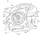
- FIG. 3 is a schematic perspective view of the turbine housing of the present embodiment as seen from the outer diameter side exhaust introduction port side.
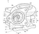
- FIG. 4 is a schematic perspective view of the turbine housing of the present embodiment as viewed from the inner diameter side exhaust introduction port side.
- FIG. 5 is a diagram in which the broken line portion shown in FIG. 3 is extracted.
- FIG. 6 is a schematic perspective view of the turbine housing of the modified example as viewed from the outer diameter side exhaust introduction port side.
- FIG. 7 is a schematic perspective view of the turbine housing of the modified example as seen from the inner diameter side exhaust introduction port side.
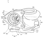
- FIG. 8 is a schematic perspective view of a modified turbine housing viewed from the waste gate port side.
- FIG. 9 is a diagram in which the broken line portion shown in FIG. 6 is extracted.
- FIG. 1 is a schematic sectional view of the supercharger TC.
- the arrow L direction shown in FIG. 1 will be described as the left side of the supercharger TC.
- the arrow R direction shown in FIG. 1 will be described as the right side of the supercharger TC.
- the supercharger TC includes a supercharger body 1.
- the supercharger body 1 includes a bearing housing 3, a turbine housing (housing) 5, and a compressor housing 7.
- the turbine housing 5 is connected to the left side of the bearing housing 3 by a fastening mechanism 9.
- the compressor housing 7 is connected to the right side of the bearing housing 3 by a fastening bolt 11.
- the exhaust turbine device T includes a bearing housing 3 and a turbine housing 5.
- the centrifugal compressor C includes a bearing housing 3 and a compressor housing 7.
- a protrusion 3 a is provided on the outer peripheral surface of the bearing housing 3.
- the protrusion 3a is provided on the turbine housing 5 side.
- the protrusion 3 a projects in the radial direction of the bearing housing 3.
- a protrusion 5 a is provided on the outer peripheral surface of the turbine housing 5.
- the protrusion 5a is provided on the bearing housing 3 side.
- the protrusion 5 a projects in the radial direction of the turbine housing 5.
- the bearing housing 3 and the turbine housing 5 are band-fastened by the fastening mechanism 9.
- the fastening mechanism 9 is composed of, for example, a G coupling.
- the fastening mechanism 9 holds the protrusions 3a and 5a.
- a bearing hole 3b is formed in the bearing housing 3.
- the bearing hole 3b penetrates in the left-right direction of the supercharger TC.
- the bearing hole 3b rotatably supports the shaft 13 via a slide bearing.
- a turbine impeller 15 is provided at the left end of the shaft 13.
- the turbine impeller 15 is arranged in the turbine housing 5.
- the turbine impeller 15 is rotatably housed in the turbine housing 5.
- a compressor impeller 17 is provided at the right end of the shaft 13.
- the compressor impeller 17 is arranged in the compressor housing 7.
- the compressor impeller 17 is rotatably accommodated in the compressor housing 7.
- An intake port 19 is formed in the compressor housing 7.
- the intake port 19 opens on the right side of the supercharger TC.
- the intake port 19 is connected to an air cleaner (not shown).
- a diffuser flow path 21 is formed by the facing surfaces of the bearing housing 3 and the compressor housing 7.
- the diffuser flow path 21 pressurizes the air.
- the diffuser flow path 21 is formed in an annular shape.
- the diffuser flow passage 21 communicates with the intake port 19 via the compressor impeller 17 inside the shaft 13 in the radial direction.
- a compressor scroll passage 23 is formed in the compressor housing 7.
- the compressor scroll flow path 23 is formed in an annular shape.
- the compressor scroll passage 23 is located, for example, outside the diffuser passage 21 in the radial direction of the shaft 13.
- the compressor scroll flow passage 23 communicates with an intake port (not shown) of the engine and the diffuser flow passage 21.
- the intake air is pressurized and accelerated in the process of flowing between the blades of the compressor impeller 17.
- the pressurized and accelerated air is pressurized in the diffuser flow passage 21 and the compressor scroll flow passage 23.
- the pressurized air is guided to the intake port of the engine.
- an exhaust flow passage 25, a housing portion 27, a communication portion 29, and an exhaust flow passage EF are formed.
- the discharge flow path 25 opens on the left side of the supercharger TC.
- the exhaust flow path 25 is connected to an exhaust gas purification device (not shown).
- the discharge flow path 25 communicates with the housing portion 27.
- the discharge flow path 25 is continuous with the housing portion 27 in the rotation axis direction of the turbine impeller 15.
- the housing portion 27 houses the turbine impeller 15.
- a communication portion 29 is arranged on the outer peripheral side of the housing portion 27 (outside in the radial direction of the turbine impeller 15).
- the communication part 29 is formed in an annular shape.
- the communication part 29 connects the accommodation part 27 and the exhaust flow path EF.
- the exhaust passage EF is arranged on the outer peripheral side of the housing portion 27.
- the exhaust flow path EF is located, for example, outside the communication portion 29 in the radial direction of the shaft 13.
- FIG. 2 is a sectional view taken along the line AA of FIG. In FIG. 2, only the outer circumference of the turbine impeller 15 is shown by a circle.
- an exhaust passage EF is formed on the outside in the radial direction of the housing portion 27 (turbine impeller 15).
- the exhaust passage EF includes a turbine scroll passage 31, an exhaust introduction port 33, and an exhaust introduction passage 35.
- the turbine scroll passage 31 is formed in an annular shape over the entire circumference of the accommodation portion 27 (turbine impeller 15).
- the turbine scroll flow passage 31 communicates with the housing portion 27 via the communication portion 29 (see FIG. 1).
- the exhaust gas inlet 33 opens outside the turbine housing 5. Exhaust gas discharged from an exhaust manifold of an engine (not shown) is introduced into the exhaust introduction port 33.
- An exhaust introduction passage 35 is formed between the exhaust introduction port 33 and the turbine scroll passage 31.
- the exhaust introduction path 35 connects the exhaust introduction port 33 and the turbine scroll passage 31.
- the exhaust gas introduction path 35 is formed in a straight line, for example.
- the exhaust gas introducing passage 35 guides the exhaust gas introduced from the exhaust gas introducing port 33 to the turbine scroll passage 31.
- the turbine scroll passage 31 guides the exhaust gas introduced from the exhaust introduction passage 35 to the accommodation portion 27 via the communication portion 29 (see FIG. 1).
- the exhaust passage EF includes an exhaust introduction port 33, an exhaust introduction passage 35, a turbine scroll passage 31 and a communication part 29.
- the exhaust flow path EF extends from the exhaust introduction port 33 to the communication part 29.
- a bypass passage 37 and a partition plate 39 are formed in the turbine housing 5.
- an inlet end OP is opened in the exhaust flow passage EF, and an outlet end (a waste gate port WP described later) is opened in the discharge flow passage 25 (see FIG. 1). More specifically, in the bypass flow passage 37, the inlet end OP is opened to the exhaust introduction passage 35 and the outlet end is opened to the discharge flow passage 25.
- the bypass passage 37 connects (connects) the exhaust introduction passage 35 and the discharge passage 25.
- a wastegate port WP (see FIG. 1) is formed at the outlet end of the bypass flow path 37.
- a wastegate valve WV capable of opening and closing the wastegate port WP is arranged at the outlet end of the bypass passage 37.
- the waste gate valve WV is arranged in the discharge flow path 25.
- the bypass flow path 37 bypasses a part of the exhaust gas flowing through the exhaust introduction path 35 by bypassing the housing portion 27 (turbine impeller 15) and the discharge flow path 25. Drain to.
- the partition plate 39 is arranged in the exhaust passage EF. More specifically, the partition plate 39 is arranged in the exhaust gas introduction port 33, the exhaust gas introduction passage 35, and the turbine scroll passage 31.
- the partition plate 39 is connected to the exhaust introduction port 33, the exhaust introduction passage 35, and the inner surface of the turbine scroll passage 31 in the rotation axis direction of the turbine impeller 15 (hereinafter, also referred to as the short side direction of the partition plate 39). To be done.
- the partition plate 39 extends in a direction away from the exhaust gas introduction port 33.
- the partition plate 39 extends along the exhaust passage EF. That is, the partition plate 39 extends along the exhaust flow direction in which the exhaust gas flows (hereinafter, also referred to as the longitudinal direction of the partition plate 39).
- the upstream side in the exhaust flow direction is simply referred to as the upstream side.
- the downstream side in the exhaust flow direction is simply referred to as the downstream side.
- the partition plate 39 has an upstream end arranged at the exhaust introduction port 33, and a downstream end facing the communication portion 29 (see FIG. 1).
- the partition plate 39 partitions (divides) the exhaust passage EF in the radial direction of the turbine impeller 15 (hereinafter, simply referred to as the radial direction).
- the partition plate 39 divides the exhaust passage EF in the radial direction of the turbine impeller 15.
- the invention is not limited to this, and the partition plate 39 may divide the exhaust passage EF in the rotation axis direction of the turbine impeller 15. That is, the lateral direction of the partition plate 39 may be the rotational axis direction of the turbine impeller 15 or the radial direction orthogonal to the rotational axis direction.
- the partition plate 39 is arranged in the exhaust introduction port 33, the exhaust introduction passage 35, and the turbine scroll passage 31.
- the invention is not limited to this, and the partition plate 39 may be disposed only in the exhaust gas introduction port 33 and the exhaust gas introduction passage 35. That is, the partition plate 39 may not be arranged in the turbine scroll passage 31.
- the partition plate 39 may be provided at least in the exhaust gas introducing port 33 and the exhaust gas introducing passage 35.
- the partition plate 39 divides the exhaust gas introduction port 33 in the radial direction.
- the exhaust gas introduction port 33 is divided by a partition plate 39 into an inner diameter side exhaust gas introduction port 33a and an outer diameter side exhaust gas introduction port 33b.
- the inner diameter side exhaust introduction port 33a is located inside the turbine impeller 15 in the radial direction with respect to the outer diameter side exhaust introduction port 33b.
- the inner diameter side exhaust introduction port 33a is formed side by side with the outer diameter side exhaust introduction port 33b in the radial direction.
- the exhaust gas discharged from the engine (not shown) is branched into two (plural) in an exhaust manifold (not shown).
- One of the two exhaust gases is introduced into the inner diameter side exhaust introduction port 33a, and the other is introduced into the outer diameter side exhaust introduction port 33b.
- the partition plate 39 divides the exhaust gas introduction passage 35 in the radial direction.
- the exhaust gas introduction path 35 is divided by a partition plate 39 into an inner diameter side exhaust gas introduction path 35a and an outer diameter side exhaust gas introduction path 35b.
- the inner diameter side exhaust introduction passage 35a is located radially inside the turbine impeller 15 with respect to the outer diameter side exhaust introduction passage 35b.
- the inner diameter side exhaust introduction passage 35a is formed side by side with the outer diameter side exhaust introduction passage 35b in the radial direction of the turbine impeller 15.
- the inner diameter side exhaust introduction passage 35a communicates with the inner diameter side exhaust introduction port 33a.
- the outer diameter side exhaust introduction passage 35b communicates with the outer diameter side exhaust introduction port 33b.
- the bypass flow passage 37 includes an inner diameter side bypass flow passage 37a and an outer diameter side bypass flow passage 37b.
- the inner diameter side bypass flow passage 37a is connected to the inner diameter side exhaust introduction passage 35a.
- the outer diameter side bypass flow passage 37b is connected to the outer diameter side exhaust introduction passage 35b.
- the inner diameter side bypass flow passage 37a connects the inner diameter side exhaust introduction passage 35a and the discharge flow passage 25.
- the outer diameter side bypass flow path 37b connects the outer diameter side exhaust gas introduction path 35b and the discharge flow path 25.
- a partition wall 41 is provided between the inner diameter side bypass flow channel 37a and the outer diameter side bypass flow channel 37b.
- the partition wall 41 has one end arranged at the inlet end OP of the bypass flow passage 37 and the other end arranged at the outlet end (waste gate port WP) of the bypass flow passage 37.
- the partition wall 41 divides the inner diameter side bypass flow channel 37a and the outer diameter side bypass flow channel 37b.
- the inner diameter side bypass passage 37a guides a part of the exhaust gas flowing through the inner diameter side exhaust introduction passage 35a (see FIG. 2) to the waste gate port WP.
- the outer diameter side bypass flow path 37b guides a part of the exhaust gas flowing through the outer diameter side bypass flow path 37b (see FIG. 2) to the waste gate port WP.
- the partition plate 39 divides the turbine scroll passage 31 in the radial direction.
- the turbine scroll passage 31 is divided by a partition plate 39 into an inner diameter side turbine scroll passage 31a and an outer diameter side turbine scroll passage 31b.
- the inner diameter side turbine scroll flow passage 31a is located radially inward of the outer diameter side turbine scroll flow passage 31b.
- the inner diameter side turbine scroll passage 31a is formed side by side with the outer diameter side turbine scroll passage 31b in the radial direction.
- the inner diameter side turbine scroll passage 31a communicates with the inner diameter side exhaust introduction passage 35a.
- the outer diameter side turbine scroll passage 31b communicates with the outer diameter side exhaust introduction passage 35b.
- the inner diameter side turbine scroll passage 31a becomes smaller in width in the radial direction as it goes away from the inner diameter side exhaust introduction passage 35a.
- the inner diameter side turbine scroll passage 31a has a radial width that decreases from the upstream side toward the downstream side.
- the outer diameter side turbine scroll passage 31b has a radial width that becomes smaller as the distance from the outer diameter side exhaust introduction passage 35b increases. That is, the outer diameter side turbine scroll passage 31b has a radial width that decreases from the upstream side to the downstream side.
- the accommodating portion 27 communicates with the inner diameter side turbine scroll passage 31a through the communicating portion 29 on the left half circumference in FIG.
- the accommodating portion 27 communicates with the outer diameter side turbine scroll passage 31b through the communicating portion 29 on the right half circumference in FIG.
- the position communicating with the inner diameter side turbine scroll passage 31a differs from the position communicating with the outer diameter side turbine scroll passage 31b in the circumferential direction of the turbine impeller 15.
- the turbine housing 5 is formed with a first tongue portion 43a and a second tongue portion 43b.
- the first tongue portion 43a is formed at the downstream end of the partition plate 39. That is, the first tongue portion 43a is formed at the end of the partition plate 39 on the side separated from the exhaust gas introduction port 33.
- the first tongue portion 43a is provided at a position facing the downstream end (downstream end) of the inner diameter side turbine scroll passage 31a.
- the first tongue portion 43a partitions the turbine scroll passage 31a on the inner diameter side and the turbine scroll passage 31b on the outer diameter side.
- the second tongue portion 43b is provided at a position facing the downstream end (downstream end) of the outer diameter side turbine scroll passage 31b.
- the second tongue portion 43b partitions the outer diameter side turbine scroll passage 31b and the inner diameter side turbine scroll passage 31a.
- the exhaust gas exhausted from the exhaust manifold of the engine (not shown) is guided to the exhaust flow path 25 via the exhaust flow path EF, the communication section 29, and the housing section 27.
- the exhaust gas guided to the exhaust passage 25 rotates the turbine impeller 15 in the distribution process.
- the rotational force of the turbine impeller 15 is transmitted to the compressor impeller 17 via the shaft 13.
- the air pressure is increased as described above. In this way, air is guided to the intake port of the engine.
- FIG. 3 is a schematic perspective view of the turbine housing 5 of the present embodiment as viewed from the outer diameter side exhaust introduction port 33b side.
- FIG. 4 is a schematic perspective view of the turbine housing 5 of the present embodiment as viewed from the inner diameter side exhaust introduction port 33a side. As shown in FIGS. 3 and 4, a groove 45 is formed in the partition plate 39.
- the groove 45 extends from the base end portion ST located closest to the exhaust gas introduction port 33 in the direction away from the exhaust gas introduction port 33 (exhaust gas flow direction).
- the base end portion ST of the groove 45 is located on the end surface of the partition plate 39 on the exhaust introduction port 33 side, and the end portion of the groove 45 is the communication portion 29 of the partition plate 39 (see FIG. 1). It is located on the side end face. That is, the groove 45 is formed along the extending direction of the partition plate 39 from the upstream end to the downstream end of the partition plate 39.
- the groove 45 is formed at the center position CP of the partition plate 39 in the lateral direction SD on the end surface of the partition plate 39 on the exhaust introduction port 33 side.
- the groove 45 is not limited to this, and on the end surface of the partition plate 39 on the exhaust introduction port 33 side, the groove 45 is displaced from the central position CP to either one of both ends BE in the lateral direction SD of the partition plate 39. It may be formed at a different position. In that case, the groove 45 may be formed so as to approach the center position CP from both ends BE along the direction away from the exhaust gas introduction port 33.
- the base end portion ST of the groove 45 is arranged at a position displaced from the center position CP of the partition plate 39 to either one of the two end portions BE, and the terminal end portion of the groove 45 is located at the center position CP of the partition plate 39. May be placed in.
- a position where the base end portion ST is arranged and a position where the end portion is arranged (center) It may be arranged at a position between the position CP) and the position CP).
- the terminal end of the groove 45 may be arranged at a position displaced from the central position CP of the partition plate 39 to either one of the both ends BE.
- FIG. 5 is a diagram in which the broken line portion shown in FIG. 3 is extracted.
- the groove 45 includes a bottom surface portion 45a and a pair of side wall portions 45b.
- the pair of side wall portions 45b are provided so as to face each other on both sides of the bottom surface portion 45a.
- the distance between the pair of side wall portions 45b increases as it goes from the bottom surface portion 45a to the surface of the partition plate 39.
- the pair of side wall portions 45b are tapered portions that are inclined with respect to the lateral direction SD of the partition plate 39.
- the present invention is not limited to this, and the distance between the pair of side wall portions 45b may not increase as the distance from the bottom surface portion 45a toward the surface of the partition plate 39 increases.
- the pair of side wall portions 45b may have a constant separation distance from the bottom surface portion 45a toward the surface of the partition plate 39.
- the base end portion ST is located on the end face of the partition plate 39 on the exhaust introduction port 33 (see FIG. 3 and FIG. 4) side, and the terminal end portion of the partition plate 39 is the communicating portion 29 (see FIG. 1)) end surface.
- the groove 45 is not limited to this, and the base end portion ST may be formed at a position separated from the end surface of the partition plate 39 on the exhaust introduction port 33 side.
- the groove 45 may be formed such that the terminal end thereof is separated from the end surface of the partition plate 39 on the side of the communication portion 29. That is, the groove 45 may be formed between the upstream end and the downstream end of the partition plate 39.
- the groove 45 of the present embodiment is formed on both side surfaces of the partition plate 39 in the thickness direction TD.
- the invention is not limited to this, and the groove 45 may be formed only on one side surface of the partition plate 39 in the thickness direction TD.
- One groove 45 of this embodiment is provided in the partition plate 39.
- the present invention is not limited to this, and a plurality of grooves 45 may be provided in the partition plate 39.
- a plurality of grooves 45 may be provided in the lateral direction SD of the partition plate 39.
- a plurality of grooves 45 may be provided along the extending direction of the partition plate 39 (exhaust gas flow direction). That is, in the partition plate 39, the groove 45 may be continuous from the base end portion ST to the end portion, or may be intermittent. In other words, the groove 45 may be continuously or intermittently formed in the partition plate 39. By forming the groove 45 intermittently, it is possible to suppress the progress of cracks more than when the groove 45 is formed continuously.
- a crack may occur in a portion of the partition plate 39 where the thermal stress is high.
- a plurality of portions having high thermal stress are generated in the partition plate 39.
- cracks occur from any of the plurality of portions with high thermal stress. Therefore, if a plurality of portions with high thermal stress occur on the partition plate 39, it becomes difficult to predict the crack occurrence position.
- the crack may propagate toward the outer surface of the turbine housing 5. When the crack reaches the outer surface of the turbine housing 5, the exhaust gas may leak from the turbine housing 5 to the outside.
- the partition plate 39 of the present embodiment includes the groove 45.
- the base end portion ST of the groove 45 is located on the end surface of the partition plate 39 on the exhaust introduction port 33 side.
- a crack is likely to occur on the end surface of the partition plate 39 on the exhaust introduction port 33 side. Since the base end portion ST of the groove 45 is located on the end surface of the partition plate 39 on the exhaust introduction port 33 side, cracks are easily generated from the base end portion ST of the groove 45. In this way, the partition plate 39 of the present embodiment can control the crack generation position so as to generate from the groove 45 (that is, an arbitrary position).
- the groove 45 extends in a direction away from the exhaust gas inlet 33 (exhaust gas flow direction). Thereby, the crack easily propagates along the extending direction of the groove 45. That is, the groove 45 can control the propagation direction of the crack. Since the groove 45 extends along the exhaust flow direction, the partition plate 39 of the present embodiment can suppress the possibility that a crack will propagate to the outer surface of the turbine housing 5. In the present embodiment, the groove 45 extends from the base end portion ST toward the communication portion 29. Therefore, the groove 45 can propagate a crack from the base end portion ST toward the communication portion 29, and can suppress the possibility that the crack propagates to the outer surface of the turbine housing 5.
- FIG. 6 is a schematic perspective view of the turbine housing 105 of the modified example as viewed from the outer diameter side exhaust introduction port 33b side.
- FIG. 7 is a schematic perspective view of the turbine housing 105 of the modified example as viewed from the inner diameter side exhaust introduction port 33a side.
- Constituent elements which are substantially the same as those of the supercharger TC of the above-described embodiment are designated by the same reference numerals and description thereof will be omitted.
- the supercharger TC of the present modified example includes a turbine housing 105 instead of the turbine housing 5 of the above embodiment.
- a partition plate 39 is formed on the turbine housing 105.
- a groove 145 is formed in the partition plate 39.
- the turbine housing 105 of this modification is different from the turbine housing 5 of the above embodiment in the shape of the groove 145 formed in the partition plate 39.
- the groove 145 extends from the base end portion ST located closest to the exhaust gas introduction port 33 in the direction away from the exhaust gas introduction port 33 (exhaust gas flow direction).
- the base end portion ST of the groove 145 is located on the end surface of the partition plate 39 on the exhaust introduction port 33 side.
- the groove 145 extends from the base end portion ST toward the bypass flow path 37.
- the groove 145 extends along the exhaust flow direction on the side surface of the partition plate 39 from the base end portion ST to the inlet end OP of the bypass passage 37.
- FIG. 8 is a schematic perspective view of the modified turbine housing 105 as viewed from the waste gate port WP side.
- the bypass channel 37 is provided with a partition wall (partition plate) 41 that partitions the inner diameter side bypass channel 37a and the outer diameter side bypass channel 37b.
- the partition wall 41 extends from the inlet end OP (see FIGS. 6 and 7) of the bypass flow path 37 to the outlet end (waste gate port WP).
- the partition wall 41 extends along the bypass flow path 37.
- the partition wall 41 extends along the exhaust flow direction (hereinafter, also referred to as the longitudinal direction of the partition wall 41) flowing through the bypass channel 37.
- the partition wall 41 is connected to the inner surface of the bypass flow path 37 in the lateral direction SD.
- the groove 145 extends from the inlet end OP of the bypass flow path 37 toward the outlet end (waste gate port WP) side.
- the groove 145 extends from the end surface of the partition wall 41 on the inlet end OP side of the bypass flow passage 37 to the end surface of the partition wall 41 on the outlet end side of the bypass flow passage 37. That is, in the present modification, the base end portion ST of the groove 145 is located on the end surface of the partition plate 39 on the exhaust introduction port 33 side, and the end portion EN of the groove 145 is on the end surface of the partition wall 41 on the outlet end side. To position.
- the groove 145 extends to the side surface of the partition wall 41 along the exhaust flow direction of the bypass passage 37.
- the groove 145 is formed at the center position CP of the partition plate 39 (see FIGS. 6 and 7) and the partition wall 41 in the lateral direction SD.
- the groove 145 is not limited to this, and on the end surface of the partition plate 39 on the exhaust introduction port 33 side, the groove 145 is displaced from the center position CP to either one of both ends BE in the lateral direction SD of the partition plate 39. It may be formed at a different position. In that case, the groove 145 may be formed so as to approach the center position CP from both ends BE along the direction away from the exhaust introduction port 33.
- the base end portion ST of the groove 145 is arranged at a position displaced from the center position CP of the partition plate 39 to either one of the end portions BE, and the end portion EN of the groove 145 is located at the center position CP of the partition wall 41. May be placed in.
- the position where the base end portion ST is arranged and the end portion EN in the lateral direction SD of the partition plate 39 (partition wall 41) are formed. It may be arranged at a position between the arranged position (center position CP).
- the present invention is not limited to this, and the end portion EN of the groove 145 may be arranged at a position displaced from the center position CP of the partition plate 39 to either one of the both end portions BE.
- FIG. 9 is a diagram in which the broken line portion shown in FIG. 6 is extracted.
- the groove 145 includes a bottom surface portion 145a and a pair of side wall portions 145b.
- the pair of side wall portions 145b are provided so as to face each other on both sides of the bottom surface portion 145a.
- the distance between the pair of side wall portions 145b increases as it goes from the bottom surface portion 145a to the surface of the partition plate 39.
- the pair of side wall portions 145b are tapered portions that are inclined with respect to the lateral direction SD of the partition plate 39.
- the present invention is not limited to this, and the pair of side wall portions 145b may not increase the separation distance from the bottom surface portion 145a toward the surface of the partition plate 39.
- the pair of side wall portions 145b may have a constant separation distance from the bottom surface portion 145a toward the surface of the partition plate 39.
- the base end portion ST is located on the end surface of the partition plate 39 on the exhaust introduction port 33 (see FIG. 6 and FIG. 7) side, and the end portion EN is the waste gate port WP ( (See FIG. 8) side end surface.
- the groove 145 may be formed at a position where the base end portion ST is separated from the end face of the partition plate 39 on the exhaust introduction port 33 side.
- the groove 145 may be formed such that the terminal end portion EN is separated from the end surface of the partition wall 41 on the waste gate port WP side.
- the groove 145 of this modification is formed on both side surfaces of the partition plate 39 and the partition wall 41 in the thickness direction TD.
- the present invention is not limited to this, and the groove 145 may be formed only on one side surface of the partition plate 39 and the partition wall 41 in the thickness direction TD.
- One groove 145 of this modification is provided in the partition plate 39 and the partition wall 41.
- the present invention is not limited to this, and a plurality of grooves 145 may be provided in the partition plate 39 and the partition wall 41.
- a plurality of grooves 145 may be provided in the lateral direction SD of the partition plate 39 and the partition wall 41.
- a plurality of grooves 145 may be provided along the extending direction (exhaust flow direction) of the partition plate 39 and the partition wall 41. That is, in the partition plate 39 and the partition wall 41, the groove 145 may be continuous from the base end portion ST to the end portion EN, or may be intermittent. In other words, the grooves 145 may be formed in the partition plate 39 and the partition wall 41 continuously or intermittently. By forming the groove 145 intermittently, the progress of cracks can be suppressed more than when the groove 145 is formed continuously.
- the partition plate 39 and the partition wall 41 of this modified example are provided with a groove 145.
- the groove 145 extends from the base end portion ST toward the outlet end (waste gate port WP) side of the bypass flow path 37. Therefore, the groove 145 can propagate the crack from the base end portion ST toward the waste gate port WP, and can suppress the possibility that the crack propagates to the outer surface of the turbine housing 5.
- the groove 45 may extend from the exhaust gas introduction port 33 (base end portion ST) toward the direction in which it approaches the discharge flow path 25.
- the turbine housing 5 on the exhaust flow passage 25 side of the exhaust flow passage EF is formed to be thicker than the exhaust flow passage EF on the side opposite to the exhaust flow passage 25. Therefore, by extending the groove 45 from the base end portion ST in the direction close to the discharge flow path 25, it is possible to suppress the possibility that a crack generated in the partition plate 39 propagates to the outer surface of the turbine housing 5. it can.
- the present disclosure can be used for an exhaust turbine device.
- Exhaust turbine device EF Exhaust flow passage 5: Turbine housing (housing) 15: Turbine impeller 25: Discharge flow passage 27: Housing portion 29: Communication portion 33: Exhaust introduction port 37: Bypass flow passage 39: Partition plate 45: Groove 45a: Bottom part 45b: A pair of side wall parts 105: Turbine housing (housing) 145: Groove 145a: Bottom part 145b: A pair of side wall parts
Landscapes
- Engineering & Computer Science (AREA)
- Mechanical Engineering (AREA)
- General Engineering & Computer Science (AREA)
- Chemical & Material Sciences (AREA)
- Combustion & Propulsion (AREA)
- Supercharger (AREA)
Abstract
排気タービン装置Tは、排気流路EFに設けられた仕切板39と、仕切板39に形成され、最も排気導入口33側に位置する基端部から、排気導入口33から離隔する方向に延在する溝45と、を備える。
Description
本開示は、排気タービン装置に関する。本出願は2018年11月21日に提出された日本特許出願第2018-218447号に基づく優先権の利益を主張するものであり、その内容は本出願に援用される。
特許文献1には、タービンハウジングの排気導入口に配される仕切板について開示がある。仕切板の外形形状は、仕切板の最小肉厚と、所定の半径の円弧とに基づいて決定される。仕切板は、決定された外形形状に形成されることで、仕切板の両端部よりも中央部で亀裂が発生しやすくなる。
しかし、仕切板に発生した亀裂の進展方向によっては、亀裂は、タービンハウジングの外面まで到達する場合がある。亀裂がタービンハウジングの外面に到達すると、排気がタービンハウジングから外部に漏出するおそれがある。
本開示は、排気の外部漏出を抑制することが可能な排気タービン装置を提供することを目的とする。
上記課題を解決するために、本開示の排気タービン装置は、タービンインペラを収容する収容部が形成されたハウジングと、ハウジングに形成され、収容部の径方向外側に位置し、ハウジングの排気導入口から、収容部に連通する連通部まで延在する排気流路と、排気流路に設けられた仕切板と、仕切板に形成され、最も排気導入口側に位置する基端部から、排気導入口から離隔する方向に延在する溝と、を備える。
溝の基端部は、仕切板のうち排気導入口側の端面に位置してもよい。
ハウジングに形成され、収容部に対して、タービンインペラの回転軸方向に連続する排出流路を備え、溝は、基端部から排出流路に近接する方向に向かって延在してもよい。
溝は、基端部から連通部に向かって延在してもよい。
ハウジングに形成され、収容部に対して、タービンインペラの回転軸方向に連続する排出流路と、排気流路に入口端が開口し、排出流路に出口端が開口するバイパス流路と、をさらに備え、溝は、バイパス流路の出口端側に向かって延在してもよい。
溝は、底面部と、底面部の両側に対向して設けられ、底面部から仕切板の表面に向かうにしたがって離隔距離が大きくなる一対の側壁部とを含んでもよい。
仕切板には、溝が断続的に形成されてもよい。
本開示によれば、排気の外部漏出を抑制することができる。
以下に添付図面を参照しながら、本開示の一実施形態について説明する。実施形態に示す寸法、材料、その他具体的な数値等は、理解を容易とするための例示にすぎず、特に断る場合を除き、本開示を限定するものではない。なお、本明細書および図面において、実質的に同一の機能、構成を有する要素については、同一の符号を付することにより重複説明を省略し、また本開示に直接関係のない要素は図示を省略する。
図1は、過給機TCの概略断面図である。図1に示す矢印L方向を過給機TCの左側として説明する。図1に示す矢印R方向を過給機TCの右側として説明する。図1に示すように、過給機TCは、過給機本体1を備える。過給機本体1は、ベアリングハウジング3、タービンハウジング(ハウジング)5、コンプレッサハウジング7を備える。タービンハウジング5は、ベアリングハウジング3の左側に締結機構9によって連結される。コンプレッサハウジング7は、ベアリングハウジング3の右側に締結ボルト11によって連結される。排気タービン装置Tは、ベアリングハウジング3およびタービンハウジング5を含む。遠心圧縮機Cは、ベアリングハウジング3およびコンプレッサハウジング7を含む。
ベアリングハウジング3の外周面には、突起3aが設けられる。突起3aは、タービンハウジング5側に設けられる。突起3aは、ベアリングハウジング3の径方向に突出する。タービンハウジング5の外周面には、突起5aが設けられる。突起5aは、ベアリングハウジング3側に設けられる。突起5aは、タービンハウジング5の径方向に突出する。ベアリングハウジング3とタービンハウジング5は、締結機構9によってバンド締結される。締結機構9は、例えば、Gカップリングで構成される。締結機構9は、突起3a、5aを挟持する。
ベアリングハウジング3には、軸受孔3bが形成される。軸受孔3bは、過給機TCの左右方向に貫通する。軸受孔3bは、すべり軸受を介してシャフト13を回転自在に軸支する。シャフト13の左端部には、タービンインペラ15が設けられる。タービンインペラ15は、タービンハウジング5内に配される。タービンインペラ15は、タービンハウジング5に回転自在に収容される。シャフト13の右端部には、コンプレッサインペラ17が設けられる。コンプレッサインペラ17は、コンプレッサハウジング7内に配される。コンプレッサインペラ17は、コンプレッサハウジング7に回転自在に収容される。
コンプレッサハウジング7には、吸気口19が形成される。吸気口19は、過給機TCの右側に開口する。吸気口19は、不図示のエアクリーナに接続される。ベアリングハウジング3とコンプレッサハウジング7の対向面によって、ディフューザ流路21が形成される。ディフューザ流路21は、空気を昇圧する。ディフューザ流路21は、環状に形成される。ディフューザ流路21は、シャフト13の径方向内側において、コンプレッサインペラ17を介して吸気口19に連通している。
コンプレッサハウジング7には、コンプレッサスクロール流路23が形成される。コンプレッサスクロール流路23は、環状に形成される。コンプレッサスクロール流路23は、例えば、ディフューザ流路21よりもシャフト13の径方向外側に位置する。コンプレッサスクロール流路23は、不図示のエンジンの吸気口と、ディフューザ流路21とに連通している。コンプレッサインペラ17が回転すると、吸気口19からコンプレッサハウジング7内に空気が吸気される。吸気された空気は、コンプレッサインペラ17の翼間を流通する過程において加圧加速される。加圧加速された空気は、ディフューザ流路21およびコンプレッサスクロール流路23で昇圧される。昇圧された空気は、エンジンの吸気口に導かれる。
タービンハウジング5には、排出流路25と、収容部27と、連通部29と、排気流路EFとが形成される。排出流路25は、過給機TCの左側に開口する。排出流路25は、不図示の排気ガス浄化装置に接続される。排出流路25は、収容部27と連通する。排出流路25は、収容部27に対して、タービンインペラ15の回転軸方向に連続する。収容部27は、タービンインペラ15を収容する。収容部27の外周側(タービンインペラ15の径方向外側)には、連通部29が配される。連通部29は、環状形状に形成される。連通部29は、収容部27と排気流路EFとを連通させる。排気流路EFは、収容部27の外周側に配される。排気流路EFは、例えば、連通部29よりもシャフト13の径方向外側に位置する。
図2は、図1のA-A線断面図である。図2では、タービンインペラ15について、外周のみを円で示す。図2に示すように、収容部27(タービンインペラ15)の径方向外側には、排気流路EFが形成される。排気流路EFは、タービンスクロール流路31と、排気導入口33と、排気導入路35とを備える。タービンスクロール流路31は、収容部27(タービンインペラ15)の全周に亘って環状に形成される。タービンスクロール流路31は、連通部29(図1参照)を介して収容部27と連通する。
排気導入口33は、タービンハウジング5の外部に開口する。排気導入口33には、不図示のエンジンの排気マニホールドから排出される排気ガスが導入される。排気導入口33とタービンスクロール流路31との間には、排気導入路35が形成される。排気導入路35は、排気導入口33とタービンスクロール流路31とを接続する。排気導入路35は、例えば、直線状に形成される。排気導入路35は、排気導入口33から導入された排気ガスをタービンスクロール流路31に導く。タービンスクロール流路31は、排気導入路35から導入された排気ガスを、連通部29(図1参照)を介して収容部27に導く。排気流路EFは、排気導入口33、排気導入路35、タービンスクロール流路31および連通部29を含む。排気流路EFは、排気導入口33から連通部29まで延在している。
タービンハウジング5には、バイパス流路37と、仕切板39とが形成される。バイパス流路37は、排気流路EFに入口端OPが開口し、排出流路25(図1参照)に出口端(後述するウェイストゲートポートWP)が開口する。より具体的に、バイパス流路37は、排気導入路35に入口端OPが開口し、排出流路25に出口端が開口する。バイパス流路37は、排気導入路35と排出流路25とを連通(接続)させる。バイパス流路37の出口端には、ウェイストゲートポートWP(図1参照)が形成される。バイパス流路37の出口端には、ウェイストゲートポートWPを開閉可能なウェイストゲートバルブWV(図1参照)が配される。ウェイストゲートバルブWVは、排出流路25内に配される。ウェイストゲートバルブWVがウェイストゲートポートWPを開いたとき、バイパス流路37は、排気導入路35を流通する排気ガスの一部を、収容部27(タービンインペラ15)を迂回して排出流路25に流出させる。
仕切板39は、排気流路EF内に配される。より具体的に、仕切板39は、排気導入口33、排気導入路35、および、タービンスクロール流路31内に配される。仕切板39は、排気導入口33、排気導入路35、および、タービンスクロール流路31の内面に対して、タービンインペラ15の回転軸方向(以下、仕切板39の短手方向ともいう)に接続される。仕切板39は、排気導入口33から離隔する方向に向かって延在する。仕切板39は、排気流路EFに沿って延在する。つまり、仕切板39は、排気ガスが流れる排気流動方向(以下、仕切板39の長手方向ともいう)に沿って延在する。以下、排気流動方向の上流側を単に上流側という。排気流動方向の下流側を単に下流側という。仕切板39は、上流側の端部が排気導入口33に配され、下流側の端部が連通部29(図1参照)に面して配される。仕切板39は、排気流路EFをタービンインペラ15の径方向(以下、単に径方向という)に仕切る(分割する)。
本実施形態では、仕切板39が排気流路EFをタービンインペラ15の径方向に分割する例について説明する。しかし、これに限定されず、仕切板39は、排気流路EFをタービンインペラ15の回転軸方向に分割してもよい。つまり、仕切板39の短手方向は、タービンインペラ15の回転軸方向であっても、回転軸方向に直交する径方向であってもよい。
本実施形態では、仕切板39が、排気導入口33、排気導入路35、および、タービンスクロール流路31内に配される例について説明する。しかし、これに限定されず、仕切板39は、排気導入口33および排気導入路35にのみ配されてもよい。つまり、仕切板39は、タービンスクロール流路31内に配されなくてもよい。仕切板39は、少なくとも排気導入口33および排気導入路35に設けられていればよい。
図2に示すように、仕切板39は、排気導入口33を径方向に分割する。排気導入口33は、仕切板39により内径側排気導入口33aと外径側排気導入口33bとに分割される。内径側排気導入口33aは、外径側排気導入口33bよりもタービンインペラ15の径方向内側に位置する。内径側排気導入口33aは、外径側排気導入口33bと径方向に並んで形成される。
ここで、不図示のエンジンから排出される排気ガスは、不図示の排気マニホールドにおいて2つ(複数)に分岐される。2つに分岐された排気ガスのうち、一方は内径側排気導入口33aに導入され、他方は外径側排気導入口33bに導入される。
仕切板39は、排気導入路35を径方向に分割する。排気導入路35は、仕切板39により内径側排気導入路35aと、外径側排気導入路35bとに分割される。内径側排気導入路35aは、外径側排気導入路35bよりもタービンインペラ15の径方向内側に位置する。内径側排気導入路35aは、外径側排気導入路35bとタービンインペラ15の径方向に並んで形成される。内径側排気導入路35aは、内径側排気導入口33aと連通する。外径側排気導入路35bは、外径側排気導入口33bと連通する。
バイパス流路37は、内径側バイパス流路37aと、外径側バイパス流路37bとを備える。内径側バイパス流路37aは、内径側排気導入路35aに接続される。外径側バイパス流路37bは、外径側排気導入路35bに接続される。内径側バイパス流路37aは、内径側排気導入路35aと排出流路25とを連通させる。外径側バイパス流路37bは、外径側排気導入路35bと排出流路25とを連通させる。
ここで、図1に示すように、内径側バイパス流路37aと外径側バイパス流路37bの間には、隔壁41が設けられる。隔壁41は、一端がバイパス流路37の入口端OPに配され、他端がバイパス流路37の出口端(ウェイストゲートポートWP)に配される。隔壁41は、内径側バイパス流路37aと、外径側バイパス流路37bとを区画する。内径側バイパス流路37aは、内径側排気導入路35a(図2参照)を流通する排気ガスの一部をウェイストゲートポートWPに導く。外径側バイパス流路37bは、外径側バイパス流路37b(図2参照)を流通する排気ガスの一部をウェイストゲートポートWPに導く。
図2に戻り、仕切板39は、タービンスクロール流路31を径方向に分割する。タービンスクロール流路31は、仕切板39により内径側タービンスクロール流路31aと、外径側タービンスクロール流路31bとに分割される。内径側タービンスクロール流路31aは、外径側タービンスクロール流路31bよりも径方向内側に位置する。内径側タービンスクロール流路31aは、外径側タービンスクロール流路31bと径方向に並んで形成される。内径側タービンスクロール流路31aは、内径側排気導入路35aと連通する。外径側タービンスクロール流路31bは、外径側排気導入路35bと連通する。
内径側タービンスクロール流路31aは、内径側排気導入路35aから遠ざかるにつれて径方向の幅が小さくなる。つまり、内径側タービンスクロール流路31aは、上流側から下流側に向かって径方向の幅が小さくなる。
外径側タービンスクロール流路31bは、外径側排気導入路35bから遠ざかるにつれて径方向の幅が小さくなる。つまり、外径側タービンスクロール流路31bは、上流側から下流側に向かって径方向の幅が小さくなる。
収容部27は、図2中、左側の半周において、連通部29を介して内径側タービンスクロール流路31aと連通する。収容部27は、図2中、右側の半周において、連通部29を介して外径側タービンスクロール流路31bと連通する。このように、収容部27は、内径側タービンスクロール流路31aと連通する位置が、外径側タービンスクロール流路31bと連通する位置とタービンインペラ15の周方向において異なる。
タービンハウジング5には、第1舌部43aと、第2舌部43bとが形成される。第1舌部43aは、仕切板39の下流側の端部に形成される。すなわち、第1舌部43aは、仕切板39の排気導入口33から離隔する側の端部に形成される。第1舌部43aは、内径側タービンスクロール流路31aの下流側の端部(下流端)に面する位置に設けられる。第1舌部43aは、内径側タービンスクロール流路31aと外径側タービンスクロール流路31bとを区画する。
第2舌部43bは、外径側タービンスクロール流路31bの下流側の端部(下流端)に面する位置に設けられる。第2舌部43bは、外径側タービンスクロール流路31bと内径側タービンスクロール流路31aとを区画する。
図1に戻り、不図示のエンジンの排気マニホールドから排出された排気ガスは、排気流路EF、連通部29、および、収容部27を介して排出流路25に導かれる。排出流路25に導かれる排気ガスは、流通過程においてタービンインペラ15を回転させる。
タービンインペラ15の回転力は、シャフト13を介してコンプレッサインペラ17に伝達される。コンプレッサインペラ17が回転すると、上記のとおりに空気が昇圧される。こうして、空気がエンジンの吸気口に導かれる。
図3は、本実施形態のタービンハウジング5を外径側排気導入口33b側から見た概略斜視図である。図4は、本実施形態のタービンハウジング5を内径側排気導入口33a側から見た概略斜視図である。図3および図4に示すように、仕切板39には、溝45が形成される。
溝45は、最も排気導入口33側に位置する基端部STから、排気導入口33から離隔する方向(排気流動方向)に延在する。本実施形態では、溝45の基端部STは、仕切板39のうち排気導入口33側の端面に位置し、溝45の終端部は、仕切板39のうち連通部29(図1参照)側の端面に位置する。つまり、溝45は、仕切板39の上流端から下流端まで、仕切板39の延在方向に沿って形成される。
溝45は、仕切板39の排気導入口33側の端面において、仕切板39の短手方向SDにおける中心位置CPに形成される。ただし、これに限定されず、溝45は、仕切板39の排気導入口33側の端面において、中心位置CPから、仕切板39の短手方向SDにおける両端部BEのうちいずれか一方側にずれた位置に形成されてもよい。その場合、溝45は、排気導入口33から離隔する方向に沿って、両端部BEから中心位置CPに近づくように形成されてもよい。すなわち、溝45の基端部STは、仕切板39の中心位置CPから両端部BEのうちいずれか一方側にずれた位置に配され、溝45の終端部は、仕切板39の中心位置CPに配されてもよい。このとき、溝45のうち基端部STと終端部の間の中間部は、仕切板39の短手方向SDにおいて、基端部STが配される位置と終端部が配される位置(中心位置CP)との間の位置に配されてもよい。なお、これに限定されず、溝45の終端部は、仕切板39の中心位置CPから両端部BEのうちいずれか一方側にずれた位置に配されてもよい。
図5は、図3に示す破線部分を抽出した図である。図5に示すように、溝45は、底面部45aと、一対の側壁部45bとを含む。一対の側壁部45bは、底面部45aの両側に対向して設けられる。一対の側壁部45bは、底面部45aから仕切板39の表面に向かうにしたがって離隔距離が大きくなる。一対の側壁部45bは、仕切板39の短手方向SDに対し傾斜するテーパ部である。溝45がテーパ部を備えることで、テーパ部を備えていない場合よりも、仕切板39に溝45を容易に形成することができる。ただし、これに限定されず、一対の側壁部45bは、底面部45aから仕切板39の表面に向かうにしたがって離隔距離が大きくならなくてもよい。例えば、一対の側壁部45bは、底面部45aから仕切板39の表面に向かって離隔距離が一定でもよい。
本実施形態の溝45は、基端部STが仕切板39のうち排気導入口33(図3および図4参照)側の端面に位置し、終端部が仕切板39のうち連通部29(図1参照)側の端面に位置する。ただし、これに限定されず、溝45は、基端部STが仕切板39のうち排気導入口33側の端面から離隔した位置に形成されてもよい。溝45は、終端部が仕切板39のうち連通部29側の端面から離隔した位置に形成されてもよい。つまり、溝45は、仕切板39の上流端から下流端までの間に形成されていればよい。
本実施形態の溝45は、仕切板39の厚さ方向TDの両側面に形成される。ただし、これに限定されず、溝45は、仕切板39の厚さ方向TDの片側面にのみ形成されてもよい。
本実施形態の溝45は、仕切板39に1つ設けられる。ただし、これに限定されず、溝45は、仕切板39に複数設けられてもよい。例えば、溝45は、仕切板39の短手方向SDに複数設けられてもよい。溝45は、仕切板39の延在方向(排気流動方向)に沿って複数設けられてもよい。つまり、仕切板39には、溝45が基端部STから終端部まで連続していてもよいし、断続していてもよい。換言すれば、仕切板39には、溝45が連続的または断続的に形成されてもよい。溝45が断続的に形成されることで、溝45が連続的に形成される場合よりも、亀裂の進展を抑制することができる。
ところで、仕切板39に熱が加わると、仕切板39の熱応力が高い部分に亀裂が発生する場合がある。通常、仕切板39に熱が加わると、仕切板39には、熱応力の高い部分が複数生じる。熱応力の高い部分が複数生じると、熱応力の高い複数の部分のうちいずれかから亀裂が発生する。したがって、仕切板39に熱応力の高い部分が複数生じると、亀裂の発生位置を予測することが困難になる。仕切板39に亀裂が発生した場合、亀裂は、タービンハウジング5の外面に向けて進展するおそれがある。亀裂がタービンハウジング5の外面に到達すると、排気ガスは、タービンハウジング5から外部に漏出するおそれがある。
そこで、本実施形態の仕切板39は、溝45を備えている。これにより、仕切板39に熱が加わると、溝45に熱応力が集中し易くなる。その結果、亀裂が溝45に発生し易くなる。なお、本実施形態では、溝45の基端部STは、仕切板39のうち排気導入口33側の端面に位置している。亀裂は、仕切板39のうち排気導入口33側の端面に生じ易い。溝45の基端部STが仕切板39のうち排気導入口33側の端面に位置することで、亀裂が溝45の基端部STから発生し易くなる。このように、本実施形態の仕切板39は、亀裂の発生位置を溝45(すなわち、任意の位置)から発生するように制御することができる。
溝45は、排気導入口33から離隔する方向(排気流動方向)に延在している。これにより、亀裂は、溝45の延在方向に沿って進展し易くなる。つまり、溝45は、亀裂の進展方向を制御することができる。溝45が排気流動方向に沿って延在することで、本実施形態の仕切板39は、亀裂がタービンハウジング5の外面に進展する可能性を抑制させることができる。本実施形態では、溝45が基端部STから連通部29に向かって延在する。そのため、溝45は、亀裂を基端部STから連通部29に向かって進展させることができ、亀裂がタービンハウジング5の外面に進展する可能性を抑制させることができる。
(変形例)
図6は、変形例のタービンハウジング105を外径側排気導入口33b側から見た概略斜視図である。図7は、変形例のタービンハウジング105を内径側排気導入口33a側から見た概略斜視図である。上記実施形態の過給機TCと実質的に等しい構成要素については、同一符号を付して説明を省略する。本変形例の過給機TCは、上記実施形態のタービンハウジング5に代えて、タービンハウジング105を備える。
図6および図7に示すように、タービンハウジング105には、仕切板39が形成されている。仕切板39には、溝145が形成される。本変形例のタービンハウジング105は、上記実施形態のタービンハウジング5と、仕切板39に形成される溝145の形状が異なる。溝145は、最も排気導入口33側に位置する基端部STから、排気導入口33から離隔する方向(排気流動方向)に延在する。本変形例では、溝145の基端部STは、仕切板39のうち排気導入口33側の端面に位置する。溝145は、基端部STからバイパス流路37に向かって延在する。溝145は、基端部STからバイパス流路37の入口端OPに至るまで、仕切板39の側面を排気流動方向に沿って延在する。
図8は、変形例のタービンハウジング105をウェイストゲートポートWP側から見た概略斜視図である。図8に示すように、バイパス流路37には、内径側バイパス流路37aと外径側バイパス流路37bとを区画する隔壁(仕切板)41が設けられる。
隔壁41は、バイパス流路37の入口端OP(図6および図7参照)から出口端(ウェイストゲートポートWP)まで延在する。隔壁41は、バイパス流路37に沿って延在する。隔壁41は、バイパス流路37を流れる排気流動方向(以下、隔壁41の長手方向ともいう)に沿って延在する。隔壁41は、短手方向SDにおいてバイパス流路37の内面と接続される。
溝145は、バイパス流路37の入口端OPから出口端(ウェイストゲートポートWP)側に向かって延在する。本変形例では、溝145は、隔壁41のうちバイパス流路37の入口端OP側の端面から隔壁41のうちバイパス流路37の出口端側の端面まで延在する。つまり、本変形例では、溝145の基端部STは、仕切板39のうち排気導入口33側の端面に位置し、溝145の終端部ENは、隔壁41のうち出口端側の端面に位置する。溝145は、バイパス流路37の排気流動方向に沿って、隔壁41の側面に延在する。
溝145は、仕切板39(図6および図7参照)および隔壁41の短手方向SDにおける中心位置CPに形成される。ただし、これに限定されず、溝145は、仕切板39の排気導入口33側の端面において、中心位置CPから、仕切板39の短手方向SDにおける両端部BEのうちいずれか一方側にずれた位置に形成されてもよい。その場合、溝145は、排気導入口33から離隔する方向に沿って、両端部BEから中心位置CPに近づくように形成されてもよい。すなわち、溝145の基端部STは、仕切板39の中心位置CPから両端部BEのうちいずれか一方側にずれた位置に配され、溝145の終端部ENは、隔壁41の中心位置CPに配されてもよい。このとき、溝145のうち基端部STと終端部ENの間の中間部は、仕切板39(隔壁41)の短手方向SDにおいて、基端部STが配される位置と終端部ENが配される位置(中心位置CP)との間の位置に配されてもよい。なお、これに限定されず、溝145の終端部ENは、仕切板39の中心位置CPから両端部BEのうちいずれか一方側にずれた位置に配されてもよい。
図9は、図6に示す破線部分を抽出した図である。図9に示すように、溝145は、底面部145aと、一対の側壁部145bとを含む。一対の側壁部145bは、底面部145aの両側に対向して設けられる。一対の側壁部145bは、底面部145aから仕切板39の表面に向かうにしたがって離隔距離が大きくなる。一対の側壁部145bは、仕切板39の短手方向SDに対し傾斜するテーパ部である。溝145がテーパ部を備えることで、テーパ部を備えていない場合よりも、仕切板39に溝145を容易に形成することができる。ただし、これに限定されず、一対の側壁部145bは、底面部145aから仕切板39の表面に向かうにしたがって離隔距離が大きくならなくてもよい。例えば、一対の側壁部145bは、底面部145aから仕切板39の表面に向かって離隔距離が一定でもよい。
本変形例の溝145は、基端部STが仕切板39のうち排気導入口33(図6および図7参照)側の端面に位置し、終端部ENが隔壁41のうちウェイストゲートポートWP(図8参照)側の端面に位置する。ただし、これに限定されず、溝145は、基端部STが仕切板39のうち排気導入口33側の端面から離隔した位置に形成されてもよい。溝145は、終端部ENが隔壁41のうちウェイストゲートポートWP側の端面から離隔した位置に形成されてもよい。
本変形例の溝145は、仕切板39および隔壁41の厚さ方向TDの両側面に形成される。ただし、これに限定されず、溝145は、仕切板39および隔壁41の厚さ方向TDの片側面にのみ形成されてもよい。
本変形例の溝145は、仕切板39および隔壁41に1つ設けられる。ただし、これに限定されず、溝145は、仕切板39および隔壁41に複数設けられてもよい。例えば、溝145は、仕切板39および隔壁41の短手方向SDに複数設けられてもよい。溝145は、仕切板39および隔壁41の延在方向(排気流動方向)に沿って複数設けられてもよい。つまり、仕切板39および隔壁41には、溝145が基端部STから終端部ENまで連続していてもよいし、断続していてもよい。換言すれば、仕切板39および隔壁41には、溝145が連続的または断続的に形成されてもよい。溝145が断続的に形成されることで、溝145が連続的に形成される場合よりも、亀裂の進展を抑制することができる。
本変形例の仕切板39および隔壁41は、溝145を備えている。これにより、上記実施形態と同様の作用効果が得られる。本変形例では、溝145が基端部STからバイパス流路37の出口端(ウェイストゲートポートWP)側に向かって延在する。そのため、溝145は、亀裂を基端部STからウェイストゲートポートWPに向かって進展させることができ、亀裂がタービンハウジング5の外面に進展する可能性を抑制させることができる。
以上、添付図面を参照しながら本開示の実施形態について説明したが、本開示はかかる実施形態に限定されないことは言うまでもない。当業者であれば、特許請求の範囲に記載された範疇において、各種の変更例または修正例に想到し得ることは明らかであり、それらについても当然に本開示の技術的範囲に属するものと了解される。
例えば、上記実施形態では、溝45がタービンスクロール流路31に沿って延在する例について説明した。しかし、これに限定されず、溝45は、排気導入口33(基端部ST)から排出流路25に近接する方向に向かって延在してもよい。排気流路EFに対し排出流路25側のタービンハウジング5は、排気流路EFに対し排出流路25とは反対側よりも肉厚に形成される。したがって、溝45を基端部STから排出流路25に近接する方向に向かって延在させることで、仕切板39に生じた亀裂がタービンハウジング5の外面に進展する可能性を抑制させることができる。
本開示は、排気タービン装置に利用することができる。
T:排気タービン装置 EF:排気流路 5:タービンハウジング(ハウジング) 15:タービンインペラ 25:排出流路 27:収容部 29:連通部 33:排気導入口 37:バイパス流路 39:仕切板 45:溝 45a:底面部 45b:一対の側壁部 105:タービンハウジング(ハウジング) 145:溝 145a:底面部 145b:一対の側壁部
Claims (7)
-
タービンインペラを収容する収容部が形成されたハウジングと、
前記ハウジングに形成され、前記収容部の径方向外側に位置し、前記ハウジングの排気導入口から、前記収容部に連通する連通部まで延在する排気流路と、
前記排気流路に設けられた仕切板と、
前記仕切板に形成され、最も前記排気導入口側に位置する基端部から、前記排気導入口から離隔する方向に延在する溝と、
を備える排気タービン装置。
-
前記溝の基端部は、前記仕切板のうち前記排気導入口側の端面に位置する請求項1に記載の排気タービン装置。
-
前記ハウジングに形成され、前記収容部に対して、前記タービンインペラの回転軸方向に連続する排出流路を備え、
前記溝は、前記基端部から排出流路に近接する方向に向かって延在する請求項1または2に記載の排気タービン装置。
-
前記溝は、前記基端部から前記連通部に向かって延在する請求項1または2に記載の排気タービン装置。
-
前記ハウジングに形成され、前記収容部に対して、前記タービンインペラの回転軸方向に連続する排出流路と、
前記排気流路に入口端が開口し、前記排出流路に出口端が開口するバイパス流路と、
をさらに備え、
前記溝は、前記バイパス流路の前記出口端側に向かって延在する請求項1または2に記載の排気タービン装置。
-
前記溝は、底面部と、前記底面部の両側に対向して設けられ、前記底面部から前記仕切板の表面に向かうにしたがって離隔距離が大きくなる一対の側壁部とを含む請求項1から5のいずれか1項に記載の排気タービン装置。
-
前記仕切板には、前記溝が断続的に形成される請求項1から6のいずれか1項に記載の排気タービン装置。
Applications Claiming Priority (2)
| Application Number | Priority Date | Filing Date | Title |
|---|---|---|---|
| JP2018218447 | 2018-11-21 | ||
| JP2018-218447 | 2018-11-21 |
Publications (1)
| Publication Number | Publication Date |
|---|---|
| WO2020105474A1 true WO2020105474A1 (ja) | 2020-05-28 |
Family
ID=70773307
Family Applications (1)
| Application Number | Title | Priority Date | Filing Date |
|---|---|---|---|
| PCT/JP2019/043843 Ceased WO2020105474A1 (ja) | 2018-11-21 | 2019-11-08 | 排気タービン装置 |
Country Status (1)
| Country | Link |
|---|---|
| WO (1) | WO2020105474A1 (ja) |
Cited By (2)
| Publication number | Priority date | Publication date | Assignee | Title |
|---|---|---|---|---|
| CN115362310A (zh) * | 2020-07-09 | 2022-11-18 | 株式会社Ihi | 涡轮以及增压器 |
| CN116234976A (zh) * | 2020-12-28 | 2023-06-06 | 三菱重工发动机和增压器株式会社 | 涡轮壳体、涡轮增压器及汽油发动机 |
Citations (6)
| Publication number | Priority date | Publication date | Assignee | Title |
|---|---|---|---|---|
| JPS52133809U (ja) * | 1976-04-07 | 1977-10-12 | ||
| JPS61218734A (ja) * | 1985-03-25 | 1986-09-29 | Mazda Motor Corp | 排気タ−ボ過給装置 |
| JPS61159629U (ja) * | 1985-03-25 | 1986-10-03 | ||
| JPH01173347U (ja) * | 1988-05-19 | 1989-12-08 | ||
| DE102004005462A1 (de) * | 2004-02-04 | 2005-06-16 | Audi Ag | Mehrflutiges Gehäuse für eine Abgasturbine eines Abgasturboladers |
| WO2006101125A1 (ja) * | 2005-03-24 | 2006-09-28 | Hitachi Metals, Ltd. | 排気系部品 |
-
2019
- 2019-11-08 WO PCT/JP2019/043843 patent/WO2020105474A1/ja not_active Ceased
Patent Citations (6)
| Publication number | Priority date | Publication date | Assignee | Title |
|---|---|---|---|---|
| JPS52133809U (ja) * | 1976-04-07 | 1977-10-12 | ||
| JPS61218734A (ja) * | 1985-03-25 | 1986-09-29 | Mazda Motor Corp | 排気タ−ボ過給装置 |
| JPS61159629U (ja) * | 1985-03-25 | 1986-10-03 | ||
| JPH01173347U (ja) * | 1988-05-19 | 1989-12-08 | ||
| DE102004005462A1 (de) * | 2004-02-04 | 2005-06-16 | Audi Ag | Mehrflutiges Gehäuse für eine Abgasturbine eines Abgasturboladers |
| WO2006101125A1 (ja) * | 2005-03-24 | 2006-09-28 | Hitachi Metals, Ltd. | 排気系部品 |
Cited By (3)
| Publication number | Priority date | Publication date | Assignee | Title |
|---|---|---|---|---|
| CN115362310A (zh) * | 2020-07-09 | 2022-11-18 | 株式会社Ihi | 涡轮以及增压器 |
| CN116234976A (zh) * | 2020-12-28 | 2023-06-06 | 三菱重工发动机和增压器株式会社 | 涡轮壳体、涡轮增压器及汽油发动机 |
| CN116234976B (zh) * | 2020-12-28 | 2025-09-19 | 三菱重工发动机和增压器株式会社 | 涡轮壳体、涡轮增压器及汽油发动机 |
Similar Documents
| Publication | Publication Date | Title |
|---|---|---|
| KR20140116967A (ko) | 터빈 하우징 및 과급기 | |
| CN103874835B (zh) | 涡轮机壳体的涡旋结构 | |
| EP2339126B1 (en) | Variable capacity turbine | |
| CN104285050A (zh) | 可变喷嘴单元以及可变容量式增压器 | |
| EP3163030B1 (en) | On-off valve device and rotary machine | |
| WO2018151267A1 (ja) | 過給機 | |
| WO2016035329A1 (ja) | ターボチャージャの排気タービン | |
| CN101372897A (zh) | 蒸汽轮机 | |
| JP6947304B2 (ja) | タービンおよび過給機 | |
| JP7364082B2 (ja) | タービンおよび過給機 | |
| US11492916B2 (en) | Turbine | |
| JP2014240612A (ja) | 遠心圧縮機及び過給機 | |
| WO2020050051A1 (ja) | タービンおよび過給機 | |
| JP7424540B2 (ja) | タービンおよび過給機 | |
| CN114846229B (zh) | 涡轮 | |
| WO2020050052A1 (ja) | 斜流タービンおよび過給機 | |
| CN113661314A (zh) | 涡轮以及增压器 | |
| WO2024053148A1 (ja) | タービン | |
| JP5988709B2 (ja) | タービンハウジング、ターボチャージャー、および、タービンハウジングと排気管との接続構造 | |
| JP2023131315A (ja) | 過給機 | |
| WO2025041333A1 (ja) | 過給機 | |
| JP2014125963A (ja) | 軸流タービン | |
| JP2022077115A (ja) | 遠心圧縮機および過給機 | |
| JP2018178909A (ja) | 過給装置 |
Legal Events
| Date | Code | Title | Description |
|---|---|---|---|
| 121 | Ep: the epo has been informed by wipo that ep was designated in this application |
Ref document number: 19887679 Country of ref document: EP Kind code of ref document: A1 |
|
| NENP | Non-entry into the national phase |
Ref country code: DE |
|
| 122 | Ep: pct application non-entry in european phase |
Ref document number: 19887679 Country of ref document: EP Kind code of ref document: A1 |
|
| NENP | Non-entry into the national phase |
Ref country code: JP |