WO2020105420A1 - 照明装置 - Google Patents
照明装置Info
- Publication number
- WO2020105420A1 WO2020105420A1 PCT/JP2019/043346 JP2019043346W WO2020105420A1 WO 2020105420 A1 WO2020105420 A1 WO 2020105420A1 JP 2019043346 W JP2019043346 W JP 2019043346W WO 2020105420 A1 WO2020105420 A1 WO 2020105420A1
- Authority
- WO
- WIPO (PCT)
- Prior art keywords
- light
- transmissive
- conductive film
- transparent conductive
- lighting device
- Prior art date
- Legal status (The legal status is an assumption and is not a legal conclusion. Google has not performed a legal analysis and makes no representation as to the accuracy of the status listed.)
- Ceased
Links
Images



Classifications
-
- F—MECHANICAL ENGINEERING; LIGHTING; HEATING; WEAPONS; BLASTING
- F21—LIGHTING
- F21V—FUNCTIONAL FEATURES OR DETAILS OF LIGHTING DEVICES OR SYSTEMS THEREOF; STRUCTURAL COMBINATIONS OF LIGHTING DEVICES WITH OTHER ARTICLES, NOT OTHERWISE PROVIDED FOR
- F21V23/00—Arrangement of electric circuit elements in or on lighting devices
- F21V23/001—Arrangement of electric circuit elements in or on lighting devices the elements being electrical wires or cables
- F21V23/002—Arrangements of cables or conductors inside a lighting device, e.g. means for guiding along parts of the housing or in a pivoting arm
-
- F—MECHANICAL ENGINEERING; LIGHTING; HEATING; WEAPONS; BLASTING
- F21—LIGHTING
- F21S—NON-PORTABLE LIGHTING DEVICES; SYSTEMS THEREOF; VEHICLE LIGHTING DEVICES SPECIALLY ADAPTED FOR VEHICLE EXTERIORS
- F21S9/00—Lighting devices with a built-in power supply; Systems employing lighting devices with a built-in power supply
- F21S9/02—Lighting devices with a built-in power supply; Systems employing lighting devices with a built-in power supply the power supply being a battery or accumulator
-
- F—MECHANICAL ENGINEERING; LIGHTING; HEATING; WEAPONS; BLASTING
- F21—LIGHTING
- F21V—FUNCTIONAL FEATURES OR DETAILS OF LIGHTING DEVICES OR SYSTEMS THEREOF; STRUCTURAL COMBINATIONS OF LIGHTING DEVICES WITH OTHER ARTICLES, NOT OTHERWISE PROVIDED FOR
- F21V3/00—Globes; Bowls; Cover glasses
- F21V3/02—Globes; Bowls; Cover glasses characterised by the shape
-
- H—ELECTRICITY
- H01—ELECTRIC ELEMENTS
- H01M—PROCESSES OR MEANS, e.g. BATTERIES, FOR THE DIRECT CONVERSION OF CHEMICAL ENERGY INTO ELECTRICAL ENERGY
- H01M10/00—Secondary cells; Manufacture thereof
- H01M10/05—Accumulators with non-aqueous electrolyte
- H01M10/052—Li-accumulators
- H01M10/0525—Rocking-chair batteries, i.e. batteries with lithium insertion or intercalation in both electrodes; Lithium-ion batteries
-
- H—ELECTRICITY
- H01—ELECTRIC ELEMENTS
- H01M—PROCESSES OR MEANS, e.g. BATTERIES, FOR THE DIRECT CONVERSION OF CHEMICAL ENERGY INTO ELECTRICAL ENERGY
- H01M10/00—Secondary cells; Manufacture thereof
- H01M10/05—Accumulators with non-aqueous electrolyte
- H01M10/058—Construction or manufacture
- H01M10/0585—Construction or manufacture of accumulators having only flat construction elements, i.e. flat positive electrodes, flat negative electrodes and flat separators
-
- H—ELECTRICITY
- H01—ELECTRIC ELEMENTS
- H01M—PROCESSES OR MEANS, e.g. BATTERIES, FOR THE DIRECT CONVERSION OF CHEMICAL ENERGY INTO ELECTRICAL ENERGY
- H01M4/00—Electrodes
- H01M4/02—Electrodes composed of, or comprising, active material
- H01M4/64—Carriers or collectors
- H01M4/66—Selection of materials
- H01M4/664—Ceramic materials
-
- H—ELECTRICITY
- H01—ELECTRIC ELEMENTS
- H01M—PROCESSES OR MEANS, e.g. BATTERIES, FOR THE DIRECT CONVERSION OF CHEMICAL ENERGY INTO ELECTRICAL ENERGY
- H01M4/00—Electrodes
- H01M4/02—Electrodes composed of, or comprising, active material
- H01M4/64—Carriers or collectors
- H01M4/66—Selection of materials
- H01M4/665—Composites
- H01M4/667—Composites in the form of layers, e.g. coatings
-
- H—ELECTRICITY
- H01—ELECTRIC ELEMENTS
- H01M—PROCESSES OR MEANS, e.g. BATTERIES, FOR THE DIRECT CONVERSION OF CHEMICAL ENERGY INTO ELECTRICAL ENERGY
- H01M50/00—Constructional details or processes of manufacture of the non-active parts of electrochemical cells other than fuel cells, e.g. hybrid cells
- H01M50/10—Primary casings; Jackets or wrappings
- H01M50/102—Primary casings; Jackets or wrappings characterised by their shape or physical structure
-
- H—ELECTRICITY
- H01—ELECTRIC ELEMENTS
- H01M—PROCESSES OR MEANS, e.g. BATTERIES, FOR THE DIRECT CONVERSION OF CHEMICAL ENERGY INTO ELECTRICAL ENERGY
- H01M50/00—Constructional details or processes of manufacture of the non-active parts of electrochemical cells other than fuel cells, e.g. hybrid cells
- H01M50/10—Primary casings; Jackets or wrappings
- H01M50/116—Primary casings; Jackets or wrappings characterised by the material
- H01M50/117—Inorganic material
-
- H—ELECTRICITY
- H01—ELECTRIC ELEMENTS
- H01M—PROCESSES OR MEANS, e.g. BATTERIES, FOR THE DIRECT CONVERSION OF CHEMICAL ENERGY INTO ELECTRICAL ENERGY
- H01M50/00—Constructional details or processes of manufacture of the non-active parts of electrochemical cells other than fuel cells, e.g. hybrid cells
- H01M50/10—Primary casings; Jackets or wrappings
- H01M50/138—Primary casings; Jackets or wrappings adapted for specific cells, e.g. electrochemical cells operating at high temperature
-
- H—ELECTRICITY
- H01—ELECTRIC ELEMENTS
- H01M—PROCESSES OR MEANS, e.g. BATTERIES, FOR THE DIRECT CONVERSION OF CHEMICAL ENERGY INTO ELECTRICAL ENERGY
- H01M50/00—Constructional details or processes of manufacture of the non-active parts of electrochemical cells other than fuel cells, e.g. hybrid cells
- H01M50/20—Mountings; Secondary casings or frames; Racks, modules or packs; Suspension devices; Shock absorbers; Transport or carrying devices; Holders
- H01M50/204—Racks, modules or packs for multiple batteries or multiple cells
- H01M50/207—Racks, modules or packs for multiple batteries or multiple cells characterised by their shape
- H01M50/209—Racks, modules or packs for multiple batteries or multiple cells characterised by their shape adapted for prismatic or rectangular cells
-
- H—ELECTRICITY
- H01—ELECTRIC ELEMENTS
- H01M—PROCESSES OR MEANS, e.g. BATTERIES, FOR THE DIRECT CONVERSION OF CHEMICAL ENERGY INTO ELECTRICAL ENERGY
- H01M50/00—Constructional details or processes of manufacture of the non-active parts of electrochemical cells other than fuel cells, e.g. hybrid cells
- H01M50/50—Current conducting connections for cells or batteries
- H01M50/543—Terminals
- H01M50/552—Terminals characterised by their shape
- H01M50/553—Terminals adapted for prismatic, pouch or rectangular cells
- H01M50/555—Window-shaped terminals
-
- F—MECHANICAL ENGINEERING; LIGHTING; HEATING; WEAPONS; BLASTING
- F21—LIGHTING
- F21S—NON-PORTABLE LIGHTING DEVICES; SYSTEMS THEREOF; VEHICLE LIGHTING DEVICES SPECIALLY ADAPTED FOR VEHICLE EXTERIORS
- F21S6/00—Lighting devices intended to be free-standing
-
- F—MECHANICAL ENGINEERING; LIGHTING; HEATING; WEAPONS; BLASTING
- F21—LIGHTING
- F21W—INDEXING SCHEME ASSOCIATED WITH SUBCLASSES F21K, F21L, F21S and F21V, RELATING TO USES OR APPLICATIONS OF LIGHTING DEVICES OR SYSTEMS
- F21W2121/00—Use or application of lighting devices or systems for decorative purposes, not provided for in codes F21W2102/00 – F21W2107/00
-
- H—ELECTRICITY
- H01—ELECTRIC ELEMENTS
- H01M—PROCESSES OR MEANS, e.g. BATTERIES, FOR THE DIRECT CONVERSION OF CHEMICAL ENERGY INTO ELECTRICAL ENERGY
- H01M2220/00—Batteries for particular applications
- H01M2220/30—Batteries in portable systems, e.g. mobile phone, laptop
Definitions
- the present invention relates to a technique of a lighting device suitable for decorative use.
- Illuminators whose light source is covered by a glass frame are often sold for decorative purposes due to their stylish and simple design. For example, it is sold as desk lighting, ceiling lighting, and foot lighting.
- Such an illuminating device is designed to produce a unique atmosphere by the light of the light source in the frame illuminating the entire surrounding glass. In order to make the best use of such characteristics and not to impair the atmosphere and landscape, it is considered desirable that the entire frame around the light source is made of light-transmissive glass.
- Patent Document 1 Although there is a lighting device with a built-in power source, a part of the lighting device such as a storage space for a dry battery or the like needs to be made into a black box, and there is a problem in design in the same point.
- the present invention has been made in view of the above circumstances, and an object thereof is to improve the design of a lighting device.
- the lighting device of the present invention is characterized in that it is provided on a light path of light emitted from a light source, and is provided with a light-transmitting lighting frame including a light-transmitting battery for driving the light source in a part or the whole thereof. ..
- the lighting device further includes a lighting frame with a conductive film including a transparent conductive film, the light-transmissive battery is in contact with the transparent conductive film, and the transparent conductive film is connected to the light source.
- the transparent conductive film is formed inside a pair of parallel linear grooves formed on a surface of the lighting frame with the conductive film, and the light transmissive battery has a flat plate shape.
- the flat plate-shaped positive electrode terminal and the flat plate-shaped negative electrode terminal respectively project from the same side and are fitted into the pair of grooves, respectively.
- the transparent conductive film is formed inside a pair of parallel grooves formed in an n-gonal shape (n is an integer of 3 or more) on the surface of the lighting frame with a conductive film, and the transparent battery is provided.
- n is an integer of 3 or more
- the transparent battery is provided.
- n in number each of which has a flat plate shape, and a flat plate-shaped positive electrode terminal and a negative electrode terminal are respectively projected from the same side and are fitted into the pair of grooves so that an n-square prism is formed. It is characterized by
- each of the n light-transmitting batteries has a positive electrode terminal and a negative electrode terminal fitted in the same groove, or a positive electrode terminal and a negative electrode terminal alternately fitted in the same groove. ..
- the number of the light-transmitting cells is n (n is an integer of 3 or more) and constitutes a side surface of the illuminating device, and the illumination frame with a conductive film is an n-sided polygon. It is characterized in that it constitutes the bottom surface of.
- the light transmissive lighting frame is made of glass.
- the design of the lighting device can be improved.
- the present invention is characterized in that a light-transmissive battery is included in a light-transmissive lighting frame forming a side surface of the lighting device. Since the battery for driving the light source is a light-transmissive battery and the light-transmissive battery is included in the light-transmissive illumination frame, a storage space for a dry battery or the like is not required, and the power source part can be excluded from the view. As a result, it is possible to provide a lighting device with improved design.
- the present embodiment the case where the light-transmissive illumination frame forming the bottom surface of the illumination device is a quadrangle will be described.
- all the light-transmissive illumination frames forming the lighting device are made of light-transmissive glass, and are therefore referred to as light-transmissive glass.
- the present invention is not limited to the contents shown in the following embodiments and examples, and can be appropriately modified and implemented within the scope of the invention.
- FIG. 1 is a diagram showing a structural example of a lighting device 100 according to the present embodiment.
- FIG. 1A is an exploded view
- FIG. 1B is an assembly view.
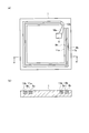
- FIG. 2 is a diagram showing the light-transmitting glass on the bottom surface.
- 2A is a top view
- FIG. 2B is a sectional view taken along line A-A '.
- the lighting device 100 mainly includes a light-transmissive glass 1 forming a bottom surface, four light-transmissive glasses 2 to 5 forming side surfaces, and a light source 6.
- the four light-transmissive glasses (light-transmissive illumination frames) 2 to 5 on the side surface are arranged on the optical path of the light emitted from the light source 6 on the bottom surface, and are used to drive the light source 6 to part or all of itself.
- a light transmissive battery 7 is included.
- the light transmissive battery 7 may be included in all the light transmissive glasses 2 to 5, or may be included in any of the light transmissive glasses 2 to 5.
- the light-transmissive glasses 2 to 5 and the light-transmissive battery 7 on the side surface each have a flat plate shape.
- Each of the light-transmissive glasses 2 to 5 includes a tab 8a and a tab 8b in a flat plate shape.
- the tabs 8a and 8b project from the same side, and a pair of grooves formed in the light-transmissive glass 1 on the bottom surface. 9a and 9b are fitted respectively.
- the tabs 8a and 8b are structured and configured as the positive electrode tab 8a and the negative electrode tab 8b, respectively, and the positive electrode tab 8a and the negative electrode tab 8b are also grooved. 9a and 9b are fitted respectively.
- the light-transmissive glass (lighting frame with conductive film) 1 on the bottom surface has a flat plate shape and is connected to the light source 6 via the two wirings 10a and 10b. It includes a film layer 11a and a second transparent conductive film layer 11b. The first transparent conductive film layer 11a and the second transparent conductive film layer 11b are formed inside a pair of parallel linear grooves 9a and 9b formed in a quadrangle on the surface. Note that the light-transmissive glass 1 on the bottom surface does not necessarily have the light-transmissivity depending on the design, unlike the light-transmissive glasses 2 to 5 on the side surfaces.
- the term “lighting frame with a conductive film” described in the claims includes both the case of having light transmissive property and the case of not having light transmissive property.
- the lighting device 100 will be described more specifically.
- At least one of the four light-transmitting glasses 2 to 5 on the side surface is a light-transmitting battery 7 provided with a positive electrode tab 8a and a negative electrode tab 8b.
- the positive electrode tab 8a and the negative electrode tab 8b are self-standing by being inserted into the groove 9a with the first transparent conductive film layer 11a and the groove 9b with the second transparent conductive film layer 11b provided on the light-transmitting glass 1 on the bottom surface, respectively. Then, it is electrically connected to the positive electrode terminal and the negative electrode terminal of the light source 6 through the first transparent conductive film layer 11a and the second transparent conductive film layer 11b which are in contact with each other by being inserted, and also through the two wirings 10a and 10b. As a result, light is emitted from the light source 6 using the light transmissive battery 7 as a power source.
- the respective positive electrode tabs 8a and negative electrode tabs 8b are provided on the light-transmitting glass 1 on the bottom surface. Two or more by inserting into the groove 9a with the one transparent conductive film layer 11a and the groove 9b with the second transparent conductive film layer 11b, respectively, and fitting the respective positive electrode tabs 8a and negative electrode tabs 8b into the same groove.
- the light transmissive batteries 7 are connected in parallel. Thereby, the battery capacity can be increased.
- a plurality of light transmissive batteries 7 can be connected to each other. It is also possible to connect in series.
- the remaining three light-transmitting glasses are glass plates processed into the same shape as the light-transmitting battery 7. To use.
- the material of the light transmissive glasses 1 to 5 is not limited to a specific material, and any material that transmits light can be used.
- a transparent glass substrate or an acrylic substrate may be used.
- the grooves 9a and 9b provided with the first transparent conductive film layer 11a and the second transparent conductive film layer 11b, respectively, can be obtained by groove processing using a general processing machine.
- the widths of the grooves 9a and 9b may be formed to correspond to the respective thicknesses of the positive electrode tab 8a and the negative electrode tab 8b of the light transmissive battery 7.
- the first transparent conductive film layer 11a and the second transparent conductive film layer 11b may be formed by a sputtering method or a vapor deposition method after applying a masking tape to the surface area other than the grooves 9a and 9b.
- the transparent conductive film include semiconductors such as tin-doped indium oxide (ITO), tin oxide (TO), fluorine-doped tin oxide (FTO), and zinc oxide (ZnO).
- the sheet resistance of the transparent conductive film is preferably 100 ⁇ / sq or less. Further, considering the light transmittance, an ITO film having a film thickness of 200 to 500 nm formed by a sputtering method is desirable.
- the light transmissive battery 7 includes a positive electrode 20 in which a transparent conductive film layer 22 and a positive electrode layer 23 are stacked on a glass substrate 21, and a negative electrode 30 in which a transparent conductive film layer 32 and a negative electrode layer 33 are stacked on a glass substrate 31. And an electrolyte layer 40.
- a battery that operates on the principle of a lithium-ion secondary battery will be described as an example.
- the positive electrode layer 23 and the negative electrode layer 33 include a substance capable of inserting and releasing lithium ions.
- the electrolyte layer 40 has lithium ion conductivity.
- the positive electrode layer 23 and the negative electrode layer 33 are arranged so as to face each other with the electrolyte layer 40 in between so as not to contact each other.
- the electrolyte layer 40 is a liquid, it is sealed with an insulating adhesive having high transparency so that the electrolyte contacts the positive electrode layer 23 and the negative electrode layer 33.
- an insulating adhesive a room temperature curing type synthetic adhesive such as a solution drying type, a moisture curing type, a two liquid mixing type, and a UV curing type is desirable.
- a silicone resin or epoxy resin In order to ensure transparency after curing, it is desirable to use a silicone resin or epoxy resin. Of these, an epoxy resin having high adhesive strength and airtightness, low oxygen / water permeability, and high resistance to various chemical substances is preferable.
- the organic electrolyte is preferably made of epoxy resin because it has higher durability.
- the material and thickness of the glass substrates 21 and 31 are not particularly limited as long as they are materials having light transmittance.
- a transparent conductive film may be formed on the glass substrates 21 and 31 by a sputtering method, a vapor deposition method, or a spin coating method.
- the transparent conductive film include semiconductors such as tin-doped indium oxide (ITO), tin oxide (TO), fluorine-doped tin oxide (FTO), and zinc oxide (ZnO).
- the sheet resistance of the transparent conductive film is preferably 100 ⁇ / sq or less, and the film thickness needs to be in the range of 100 to 500 nm. Further, in consideration of light transmittance, an ITO film having a film thickness of 100 to 200 nm is desirable by the sputtering method.
- the positive electrode layer 23 and the negative electrode layer 33 are obtained by forming a material capable of inserting and releasing lithium ions on the transparent conductive films 22 and 32 by a sputtering method, a vapor deposition method or a spin coating method.
- a sputtering method a material capable of inserting and releasing lithium ions on the transparent conductive films 22 and 32 by a sputtering method, a vapor deposition method or a spin coating method.
- the film thickness is thin, but it is desirable that the film is formed by a sputtering method within a range of 100 to 500 nm where a charge / discharge capacity can be obtained.
- an oxide such as lithium cobalt oxide (LiCoO 2 ), lithium manganate (LiMn 2 O 4 ), lithium iron phosphate (LiFePO 4 ), or lithium nickel oxide (LiNiO 2 ) can be used.
- the negative electrode layer 33 includes lithium titanate (LoTi 2 O 4 , Li 4 Ti 5 O 12 ), titanium oxide (TiO 2 ), zinc oxide (ZnO), tin oxide (TO), indium oxide (In 2 O 3 ).
- An oxide such as tin-doped indium oxide (ITO) or fluorine-doped tin oxide (FTO) can be used. The combination may be selected such that the electrode potential of the negative electrode layer 33 is lower than that of the positive electrode layer 23.
- the electrolyte layer 40 has transparency in which a metal salt containing lithium ions such as lithium bistrifluoromethanesulfonylimide (LiTFSI), lithium perchlorate (LiClO 4 ), lithium hexafluorophosphate (LiPF 6 ) is dissolved.
- a metal salt containing lithium ions such as lithium bistrifluoromethanesulfonylimide (LiTFSI), lithium perchlorate (LiClO 4 ), lithium hexafluorophosphate (LiPF 6 ) is dissolved.
- LiTFSI lithium bistrifluoromethanesulfonylimide
- LiClO 4 lithium perchlorate
- LiPF 6 lithium hexafluorophosphate
- organic solvent examples include dimethyl sulfoxide (DMSO), tetraethylene glycol dimethyl ether (TEGDME), dimethyl carbonate (DMC), methyl ethyl carbonate (MEC), methyl propyl carbonate (MPC), methyl isopropyl carbonate (MIPC), methyl butyl carbonate (MBC).
- DMSO dimethyl sulfoxide
- TEGDME tetraethylene glycol dimethyl ether
- DMC dimethyl carbonate
- MEC methyl ethyl carbonate
- MEC methyl propyl carbonate
- MIPC methyl isopropyl carbonate
- MPC methyl butyl carbonate
- aqueous electrolytic solution an aqueous solution in which a metal salt containing sodium ions such as LiClO 4 is dissolved in water, or lithium obtained by combining a lithium salt such as LiTFSI or lithium bis (pentafluoroethanesulfonyl) imide (LiBETI) with a very small amount of water.
- a lithium salt such as LiTFSI or lithium bis (pentafluoroethanesulfonyl) imide (LiBETI)
- LiBETI lithium bis (pentafluoroethanesulfonyl) imide
- hydrate melt hydrate melt
- a solid electrolyte such as a conventional solid electrolyte containing lithium ions or a polymer electrolyte can be used as long as it transmits visible light.
- the side light-transmitting glasses 2 to 5 each include a square light-transmitting battery 7.
- lithium cobalt oxide (LiCoO 2 ) was used as the positive electrode layer 23
- lithium titanate (Li 4 Ti 5 O 12 ) was used as the negative electrode layer 33
- lithium bistrifluorocarbonate was added to methylpropyl carbonate (PC).
- a solution of methanesulfonylimide (LiTFSI) is used as the electrolyte layer 40.
- a light-transmitting glass 1 having a bottom surface as shown in FIG. 2 was produced.
- glass having a length of 150 mm, a width of 150 mm, and a thickness of 20 mm was used as the glass substrate.
- a pair of parallel linear grooves 9a and 9b were formed in a quadrangle having a side of about 110 mm.
- both ends of the grooves 9a and 9b are positioned 20 mm apart from one corner of the glass substrate.
- the grooves 9a and 9b each had a width of 0.8 mm and a depth of 10 mm, and the gap width between the grooves was 0.5 mm.
- a masking tape is attached to the surface portion other than the formed grooves 9a and 9b, and an ITO target is formed on the glass substrate by a sputtering method to form an ITO layer having a film thickness of 300 nm on the side surface and the bottom surface inside the groove. did.
- a general 5 mm LED lamp (ultra high brightness 5 mm red LEDOS5RKA5111P) was used as the light source 6, and the positive electrode terminal and the negative electrode terminal were respectively connected to the ITO layers formed in the grooves 9a and 9b of the light transmissive glass 1.
- the positive electrode terminal was connected to the inner groove and the negative electrode terminal was connected to the outer groove.
- the positive electrode layer 23 or the negative electrode layer 33 was formed on the remaining surface area 100 mm ⁇ 90 mm of the ITO layer by masking the edge 100 mm ⁇ 10 mm of the ITO layer surface area 100 mm ⁇ 100 mm. In this way, the ITO layer was partially exposed as a positive electrode tab or a negative electrode tab.
- the positive electrode layer 23 and the negative electrode layer 33 were formed by sputtering LiCoO 2 and Li 4 Ti 5 O 12 targets, respectively.
- the average transmittances of the obtained positive electrode (LiCoO 2 / ITO / glass) and negative electrode (Li 4 Ti 5 O 12 / ITO / glass) in the visible light region were 30% and 80%, respectively.
- the periphery of the surface area where the positive electrode layer 23 and the negative electrode layer 33 were formed was adhered to each other with an insulating adhesive so that the positive electrode layer 23 and the negative electrode layer 33 face each other at a distance of 0.5 mm.
- a part (about 10 mm) of the periphery was not adhered to provide an electrolyte solution injection port.
- An epoxy resin which is a two-component room temperature curable adhesive, was used as the adhesive. It was confirmed that the mixture was cured in about 60 minutes after mixing the two liquids, and the color after curing was pale yellow and semitransparent.
- the electrolytic solution injection port is sealed with the same adhesive as described above, and cured overnight. Got a battery in. Four of these batteries were made.
- the average transmittance in the visible light range was 25%, and it was confirmed visually that the battery has light transmittance.
- the light transmissive battery was charged at room temperature up to 3V using a commercially available charge / discharge measurement system (SD8 charge / discharge system manufactured by Hokuto Denko).
- the four positive electrode tabs and the negative electrode tabs of the four light-transmissive batteries 7 formed in the second step were inserted into the four square grooves of the light-transmissive glass on the bottom surface formed in the first step, so as to be self-supported and fixed.
- the inside was used as a positive electrode tab and the outside was used as a negative electrode tab.
- the light transmissive battery was installed on the light transmissive glass to establish conduction, and the LED illumination was turned on. The lighting time was about one day.
- the light transmissive battery 7 can be repeatedly used by recharging with a separately prepared charge / discharge measurement system.
- Various charging methods can be considered. For example, a method of removing the light transmissive battery 7 (light transmissive glasses 2 to 5 on the side surface) from the light transmissive glass 1 and charging the battery can be considered.
- the positive electrode terminal and the negative electrode terminal of the light source 6 are disconnected from the first transparent conductive film layer 11a and the second transparent conductive film layer 11b, and the first transparent conductive film layer 11a and the second transparent conductive film layer 11a are disconnected.
- a method of connecting a charging device to the film layer 11b can be considered.
- a part of the light-transmissive glasses 2 to 5 forming the frame of the lighting device 100 is composed of the light-transmissive battery 7, so that the power supply part does not come into view.
- the lighting device 100 that does not impair the design can be provided.
- the light-transmissive glass 1 on the bottom surface is a quadrangle and the lighting device 100 is a quadrangular prism has been described.
- the illuminating device 100 may be formed into an n-sided prism by combining with the light-transmitting glass 1.
- Reference numeral 100 Lighting device 1 ... Light-transmitting glass on the bottom surface 2-5 ... Light-transmitting glass on the side surface 6 ... Light source 7 ... Light-transmitting battery 8a ... Tab / positive electrode tab 8b ... Tab / negative electrode tab 9a, 9b ... Groove 10a, 10b ... Wiring 11a ... 1st transparent conductive film layer 11b ... 2nd transparent conductive film layer 20 ... Positive electrode 21 ... Glass substrate 22 ... Transparent conductive film layer 23 ... Positive electrode layer 30 ... Negative electrode 31 ... Glass substrate 32 ... Transparent conductive film layer 33 ... Negative electrode layer 40 ... Electrolyte layer
Landscapes
- Chemical & Material Sciences (AREA)
- Engineering & Computer Science (AREA)
- Chemical Kinetics & Catalysis (AREA)
- Electrochemistry (AREA)
- General Chemical & Material Sciences (AREA)
- General Engineering & Computer Science (AREA)
- Materials Engineering (AREA)
- Manufacturing & Machinery (AREA)
- Composite Materials (AREA)
- Ceramic Engineering (AREA)
- Inorganic Chemistry (AREA)
- Secondary Cells (AREA)
- Connection Of Batteries Or Terminals (AREA)
- Non-Portable Lighting Devices Or Systems Thereof (AREA)
- Battery Mounting, Suspending (AREA)
- Hybrid Cells (AREA)
- Cell Separators (AREA)
Abstract
照明装置のデザイン性を改善する。照明装置(100)は、光源(6)から放射される光の光路上に配置され、自体の一部又は全体に光源(6)を駆動する光透過性電池(7)を含む側面の光透過性ガラス(2~5)と、透明導電膜を含む底面の光透過性ガラス(1)と、を備え、光透過性電池(7)は、一対の透明導電膜層に接触し、一対の透明導電膜層は、光源(6)に接続されている。また、一対の透明導電膜は、底面の光透過性ガラス(1)の表面に形成された平行な直線状の一対の溝(9a,9b)の内側に形成され、光透過性電池(7)の平板状の正極タブ(8a)と負極タブ(8b)は、一対の溝(9a,9b)にそれぞれ嵌合する。
Description
本発明は、装飾用途に適する照明装置の技術に関する。
ガラス製のフレームで光源が覆われた照明装置は、そのデザインのお洒落さやシンプルさから装飾用途に多く販売されている。例えば、卓上照明、天井照明、フットライトとして販売されている。このような照明装置は、フレーム内の光源の光が周囲のガラス全体に当たることで特有の雰囲気を演出するデザインとなっている。このような特徴を最大限に活かし、雰囲気や景観を損なわないためには、光源周囲のフレーム全域が光透過性のガラスであることが望ましいと考えられる。
ペンダント照明、frasco[glass]、[online]、[2018年10月16日検索]、インターネット<URL:https://platz.hamazo.tv/e2647349.html>
しかし、従来の照明装置は、一般に、電源は内蔵されておらず、電源コードを用いて外部電源に接続される構造であるため、電源が視界に入るという点でデザイン性に問題がある(非特許文献1)。電源内蔵型の照明装置もあるが、乾電池等の収納スペース等、照明装置の一部をブラックボックス化しなければならず、同様の点でデザイン性に問題がある。
本発明は、上記事情を鑑みてなされたものであり、照明装置のデザイン性を改善することを目的とする。
本発明の照明装置は、光源から放射される光の光路上に配置され、自体の一部又は全体に前記光源を駆動する光透過性電池を含む光透過性照明フレームを備えることを特徴とする。
上記照明装置において、透明導電膜を含む導電膜付照明フレームを更に備え、前記光透過性電池は、前記透明導電膜に接触し、前記透明導電膜は、前記光源に接続されていることを特徴とする。
上記照明装置において、前記透明導電膜は、前記導電膜付照明フレームの表面に形成された平行な直線状の一対の溝の内部に形成され、前記光透過性電池は、平板状の形状を備え、平板状の正極端子と負極端子が、同一側からそれぞれ突起し、前記一対の溝にそれぞれ嵌合することを特徴とする。
上記照明装置において、前記透明導電膜は、前記導電膜付照明フレームの表面にn角形(nは3以上の整数)に形成された平行な一対の溝の内部に形成され、前記光透過性電池は、nつであり、それぞれ、平板状の形状を備え、平板状の正極端子と負極端子が、同一側からそれぞれ突起し、n角柱が形成されるように前記一対の溝にそれぞれ嵌合することを特徴とする。
上記照明装置において、前記nつの光透過性電池は、それぞれ、正極端子と負極端子がそれぞれ同じ溝に嵌合し、又は正極端子と負極端子が交互に同じ溝に嵌合することを特徴とする。
上記照明装置において、前記光透過性電池は、nつ(nは3以上の整数)であり、前記照明装置の側面を構成し、前記導電膜付照明フレームは、n角形であり、前記照明装置の底面を構成することを特徴とする。
上記照明装置において、前記光透過性照明フレームは、ガラスで構成されていることを特徴とする。
本発明によれば、照明装置のデザイン性を向上できる。
本発明は、照明装置の側面を構成する光透過性照明フレームに、光透過性電池を含めることを特徴とする。光源を駆動するための電池を光透過性電池とし、その光透過性電池を光透過性照明フレームに含めるので、乾電池等の収容スペースを不要とし、電源部分を視界から排除できる。その結果、デザイン性を向上した照明装置を提供できる。
以下、本実施形態では、照明装置の底面を構成する光透過性照明フレームが四角形である場合について説明する。なお、本実施形態では、照明装置を構成する全ての光透過性照明フレームを光透過性のガラスで構成し、それゆえに光透過性ガラスと称する。なお、本発明は、下記実施形態及び実施例に示した内容に限定されるものではなく、その要旨を変更しない範囲において、適宜変更して実施できるものである。
図1は、本実施形態に係る照明装置100の構造例を示す図である。図1(a)は分解図であり、図1(b)は組立図である。図2は、底面の光透過性ガラスを示す図である。図2(a)は上面図であり、図2(b)はA-A’の断面図である。
照明装置100は、図1に示すように、主として、底面を構成する光透過性ガラス1と、側面を構成する4つの光透過性ガラス2~5と、光源6と、備えて構成される。
側面の4つの光透過性ガラス(光透過性照明フレーム)2~5は、底面の光源6から放射される光の光路上に配置され、自体の一部又は全体に光源6を駆動するための光透過性電池7を含む。光透過性電池7は、全ての光透過性ガラス2~5にそれぞれ含めてもよいし、いずれかの光透過性ガラス2~5に含めてもよい。
側面の光透過性ガラス2~5と光透過性電池7は、それぞれ平板状の形状を備える。光透過性ガラス2~5は、それぞれ、平板状のタブ8aとタブ8bを備え、タブ8aとタブ8bは、同一側からそれぞれ突起し、底面の光透過性ガラス1に形成された一対の溝9a,9bにそれぞれ嵌合する。側面の光透過性ガラス2~5に光透過性電池7が含まれる場合、タブ8aとタブ8bはそれぞれ正極タブ8aと負極タブ8bとして構造化及び構成され、正極タブ8aと負極タブ8bも溝9a,9bにそれぞれ嵌合する。
底面の光透過性ガラス(導電膜付照明フレーム)1は、図2に示すように、平板状の形状を備え、2つの配線10a,10bを介して光源6にそれぞれ接続された第一透明導電膜層11aと第二透明導電膜層11bを含む。第一透明導電膜層11aと第二透明導電膜層11bは、表面に四角形に形成された平行な直線状の一対の溝9a,9bの内側に形成される。なお、底面の光透過性ガラス1は、側面の光透過性ガラス2~5と異なり、デザインによっては、必ずしも光透過性を備える必要はない。特許請求の範囲に記載した「導電膜付照明フレーム」の単語には、光透過性を備える場合と光透過性を備えない場合の両方を含む。
以下、照明装置100について、より具体的に説明する。
側面の4つの光透過性ガラス2~5のうち少なくとも1つは、正極タブ8aと負極タブ8bが設けられた光透過性電池7である。正極タブ8aと負極タブ8bは、底面の光透過性ガラス1に設けられた第一透明導電膜層11a付の溝9aと第二透明導電膜層11b付の溝9bにそれぞれ差し込まれることで自立し、差し込むことで接触した第一透明導電膜層11aと第二透明導電膜層11bを介し、更に2つの配線10a,10bを介して、光源6の正極端子と負極端子にそれぞれ導通する。これにより、光透過性電池7を電源として光源6から光が放射される。
側面の4つの光透過性ガラス2~5のうち少なくとも2つ以上が光透過性電池7である場合、それぞれの正極タブ8aと負極タブ8bが、底面の光透過性ガラス1に設けられた第一透明導電膜層11a付の溝9aと第二透明導電膜層11b付の溝9bにそれぞれ差し込まれ、それぞれの正極タブ8aと負極タブ8bがそれぞれ同じ溝に嵌合することで、2つ以上の光透過性電池7が並列に接続される。これにより、電池容量を増すことができる。また、光透過性電池7の正極タブ8aと負極タブ8bの差し込む向きを変え、それぞれの正極タブ8aと負極タブ8bを交互に同じ溝に嵌合することで、複数の光透過性電池7同士を直列に接続することも可能である。
側面の4つの光透過性ガラス2~5のうち1つのみが光透過性電池7の場合、残りの3つの光透過性ガラスは、光透過性電池7と同じ形状に加工したガラス製の板を使用する。
光透過性ガラス1~5の材質は、特定の材質に限定されず、光を透過するものであればよい。例えば、透明なガラス基板やアクリル基板を使用すればよい。第一透明導電膜層11aと第二透明導電膜層11bがそれぞれ設けられた溝9a,9bは、一般的な加工機を用いて溝加工することで得られる。溝9a,9bの各幅は、光透過性電池7の正極タブ8aと負極タブ8bの各厚みに対応した幅で形成すればよい。第一透明導電膜層11aと第二透明導電膜層11bは、それぞれの溝9a,9b以外の表面領域にマスキングテープを施した上でスパッタリング法や蒸着法で膜を形成すればよい。透明導電膜の種類としては、スズドープ酸化インジウム(ITO)、酸化スズ(TO)、フッ素ドープ酸化スズ(FTO)、酸化亜鉛(ZnO)等の半導体があげられる。透明導電膜のシート抵抗は100Ω/sq以下であることが望ましい。更に、光透過性を考慮すると、スパッタリング法で形成した200~500nmの膜厚のITO膜が望ましい。
次に、図3を用いて、側面の光透過性ガラス2~5を成す光透過性電池7について説明する。光透過性電池7は、ガラス基板21上に透明導電膜層22と正極層23が積層された正極20と、ガラス基板31上に透明導電膜層32と負極層33が積層された負極30と、電解質層40と、を少なくとも含む。本実施形態では、リチウムイオン二次電池の原理で作動する電池を例に説明する。
正極層23と負極層33は、リチウムイオンの挿入及び脱離が可能な物質を含む。電解質層40は、リチウムイオン導電性を有する。正極層23と負極層33は、互いに接触しないように電解質層40を介して対向するように配置されている。電解質層40が液体の場合、透明度の高い絶縁性接着剤で電解質が正極層23と負極層33に接触するように封止されている。絶縁性接着剤としては、溶液乾燥型、湿気硬化型、二液混合型、UV硬化型のような室温硬化型タイプの合成系接着剤が望ましい。硬化後の透明度を確保するためには、シリコン樹脂製又はエポキシ樹脂製が望ましい。これらのうち、接着力及び機密性が強く、酸素・水分の透過性が低く、種々の化学物質に対する耐性が高いエポキシ樹脂製が望ましい。特に、有機電解液には、エポキシ樹脂製の方が高い耐久性を有するため望ましい。
ガラス基板21,31は、光透過性を有する材料であれば、材質や厚みは特に限定はされない。
透明導電膜層22,32は、ガラス基板21,31上にスパッタリング法や蒸着法やスピンコート法により透明導電膜を形成すればよい。透明導電膜の種類としては、スズドープ酸化インジウム(ITO)、酸化スズ(TO)、フッ素ドープ酸化スズ(FTO)、酸化亜鉛(ZnO)等の半導体があげられる。透明導電膜のシート抵抗は100Ω/sq以下であることが望ましく、膜厚は100~500nmの範囲にする必要がある。また、光透過性を考慮すると、スパッタリング法で100~200nmの膜厚のITO膜が望ましい。
正極層23と負極層33は、リチウムイオンの挿入・脱離が可能な材料をスパッタリング法や蒸着法やスピンコート法により透明導電膜22,32上に形成することで得られる。光透過性を考慮すると、膜厚は薄い方が望ましいが、充放電容量が得られる100~500nmの範囲でスパッタリング法により形成するのが望ましい。
正極層23には、コバルト酸リチウム(LiCoO2)、マンガン酸リチウム(LiMn2O4)、リン酸鉄リチウム(LiFePO4)、ニッケル酸リチウム(LiNiO2)等の酸化物を用いることができる。
負極層33には、チタン酸リチウム(LoTi2O4、Li4Ti5O12)、酸化チタン(TiO2)、酸化亜鉛(ZnO)、酸化スズ(TO)、酸化インジウム(In2O3)、スズドープ酸化インジウム(ITO)、フッ素ドープ酸化スズ(FTO)等の酸化物を用いることができる。正極層23よりも負極層33の電極電位が低くなるような組合せで選定すればよい。
電解質層40には、リチウムビストリフルオロメタンスルホニルイミド(LiTFSI)、過塩素酸リチウム(LiClO4)、六フッ化リン酸リチウム(LiPF6)等のリチウムイオンを含む金属塩を溶解した透明性を有する有機電解液又は水系電解液を使用できる。
有機溶媒としては、ジメチルスルホキシド(DMSO)、テトラエチレングリコールジメチルエーテル(TEGDME)、炭酸ジメチル(DMC)、炭酸メチルエチル(MEC)、炭酸メチルプロピル(MPC)、炭酸メチルイソプロピル(MIPC)、炭酸メチルブチル(MBC)、炭酸ジエチル(DEC)、炭酸エチルプロピル(EPC)、炭酸エチルイソプロピル(EIPC)、炭酸エチルブチル(EBC)、炭酸ジプロピル(DPC)、炭酸ジイソプロピル(DIPC)、炭酸ジブチル(DBC)、炭酸エチレン(EC)、炭酸プロピレン(PC)、炭酸1,2-ブチレン(1,2-BC)のような単一溶媒、炭酸エチレン(EC)及び炭酸ジメチル(DMC)(体積比1:1)の混合溶媒、EC及び炭酸ジエチル(DEC)のような混合溶媒等を用いることができる。
水系電解液としては、LiClO4等のナトリウムイオンを含む金属塩を水に溶解した水溶液、LiTFSIやリチウムビス(ペンタフルオロエタンスルホニル)イミド(LiBETI)等のリチウム塩を極めて少量の水に交合したリチウムイオン伝導性液体(ハイドレートメルト)を挙げることができる。また、従来のリチウムイオンを含む固体電解質やポリマー電解質等の固体状の電解質も可視光を透過するものであれば使用することができる。
以降の実施例では、底面に四角形の光透過性ガラス1を用いることに加え、側面の光透過性ガラス2~5が四角形の光透過性電池7をそれぞれ含む場合について説明する。なお、光透過性電池7については、コバルト酸リチウム(LiCoO2)を正極層23とし、チタン酸リチウム(Li4Ti5O12)を負極層33とし、炭酸メチルプロピル(PC)にリチウムビストリフルオロメタンスルホニルイミド(LiTFSI)を溶解したものを電解質層40とする。
<実施例>
(第1工程:底面の光透過性ガラス1の作製)
まず、図2に示したような底面の光透過性ガラス1を作製した。ガラス基板には、図4に示すように、縦150mm、横150mm、厚さ20mmのガラスを用いた。このガラス基板の表面に、平行な直線状の一対の溝9a,9bを1辺が約110mmとなる四角形に形成した。このとき、溝9a,9bの同一端部に配線10a,10bを接続することを踏まえ、溝9a,9bの両端部がガラス基板の一隅から20mm離れた所に位置するようにする。溝9a,9bは、それぞれ、幅0.8mm、深さ10mmとし、溝間の間隙幅は、0.5mmとした。
(第1工程:底面の光透過性ガラス1の作製)
まず、図2に示したような底面の光透過性ガラス1を作製した。ガラス基板には、図4に示すように、縦150mm、横150mm、厚さ20mmのガラスを用いた。このガラス基板の表面に、平行な直線状の一対の溝9a,9bを1辺が約110mmとなる四角形に形成した。このとき、溝9a,9bの同一端部に配線10a,10bを接続することを踏まえ、溝9a,9bの両端部がガラス基板の一隅から20mm離れた所に位置するようにする。溝9a,9bは、それぞれ、幅0.8mm、深さ10mmとし、溝間の間隙幅は、0.5mmとした。
そして、形成した溝9a,9b以外の表面部分にマスキングテープを貼り、ITOターゲットをスパッタリング法によりガラス基板上に成膜することで、溝内部の側面と底面に膜厚が300nmのITO層を形成した。
光源6には、一般的な5mmのLEDランプ(超高輝度5mm赤色LEDOS5RKA5111P)を用い、光透過性ガラス1の各溝9a,9bに形成したITO層に正極端子と負極端子をそれぞれ接続した。内側の溝に正極端子を接続し、外側の溝に負極端子を接続した。
(第2工程:側面の光透過性電池(光透過性ガラス2~5)の作製)
次に、ガラス基板には、縦100mm、横100mm、厚さ0.7mmのガラスを2つ準備した。これらそれぞれの片面全面に透明導電膜層22,32としてITOターゲットをスパッタリング法により成膜した。膜厚は200nmとした。正極層23と負極層33は、ITO層の表面の一部にスパッタリング法により成膜した。膜厚はいずれも100nmとした。ITO層表面領域100mm×100mmのうち端100mm×10mmにマスクをすることで、ITO層の残りの表面領域100mm×90mmに正極層23又は負極層33を形成した。このようにしてITO層を正極タブ又は負極タブとして一部露出した。
次に、ガラス基板には、縦100mm、横100mm、厚さ0.7mmのガラスを2つ準備した。これらそれぞれの片面全面に透明導電膜層22,32としてITOターゲットをスパッタリング法により成膜した。膜厚は200nmとした。正極層23と負極層33は、ITO層の表面の一部にスパッタリング法により成膜した。膜厚はいずれも100nmとした。ITO層表面領域100mm×100mmのうち端100mm×10mmにマスクをすることで、ITO層の残りの表面領域100mm×90mmに正極層23又は負極層33を形成した。このようにしてITO層を正極タブ又は負極タブとして一部露出した。
正極層23と負極層33は、それぞれLiCoO2、Li4Ti5O12ターゲットをスパッタリング法により形成した。得られた正極(LiCoO2/ITO/ガラス)と負極(Li4Ti5O12/ITO/ガラス)の可視光域の平均透過率は、それぞれ30%、80%であった。
そして、正極層23と負極層33が0.5mmの距離で互いに対向するよう、絶縁性接着剤で正極層23と負極層33が形成された表面領域の周囲を互いに接着した。この際、周囲の一部(約10mm)を接着しないことで、電解液注入口を設けた。接着剤には、二液室温硬化型接着剤のエポキシ樹脂を用いた。二液混合後、約60分で硬化したことが確認され、硬化後の色は淡黄色半透明であった。
その後、電解液注入口から電解質層40の電解液として透明な1mol/lのLiTFSI/PC溶液を注入した後、電解液注入口を上述と同様の接着剤で封止し、一晩硬化させることで電池を得た。この電池を4つ作成した。
可視光域の平均透過率は25%であり、目視でも光透過性を有する電池であることを確認した。光透過性電池の充電は、市販の充放電測定システム(北斗電工社製、SD8充放電システム)を用いて、3Vまで室温で充電を行った。
(第3工程:照明装置の組み立て及び照明動作)
その後、第2工程で作成した4つの光透過性電池7の正極タブと負極タブを、第1工程で作成した底面の光透過性ガラスの四角形の4辺の溝に差し込むことで自立固定した。内側を正極タブ、外側を負極タブとした。このようにして光透過性ガラス上に光透過性電池を設置することで導通が行われ、LED照明が点灯した。点灯時間は約1日であった。
その後、第2工程で作成した4つの光透過性電池7の正極タブと負極タブを、第1工程で作成した底面の光透過性ガラスの四角形の4辺の溝に差し込むことで自立固定した。内側を正極タブ、外側を負極タブとした。このようにして光透過性ガラス上に光透過性電池を設置することで導通が行われ、LED照明が点灯した。点灯時間は約1日であった。
(第4工程:光透過性電池の充電)
別途用意した充放電測定システムにより再度充電することで、光透過性電池7を繰り返し使用することが可能であることを確認した。充電方法については、様々な方法が考えられる。例えば、光透過性電池7(側面の光透過性ガラス2~5)を光透過性ガラス1から取り外して充電する方法が考えられる。組み立てた状態で充電する場合は、第一透明導電膜層11aと第二透明導電膜層11bから光源6の正極端子と負極端子の接続を外し、第一透明導電膜層11aと第二透明導電膜層11bに充電装置を接続する方法が考えられる。
別途用意した充放電測定システムにより再度充電することで、光透過性電池7を繰り返し使用することが可能であることを確認した。充電方法については、様々な方法が考えられる。例えば、光透過性電池7(側面の光透過性ガラス2~5)を光透過性ガラス1から取り外して充電する方法が考えられる。組み立てた状態で充電する場合は、第一透明導電膜層11aと第二透明導電膜層11bから光源6の正極端子と負極端子の接続を外し、第一透明導電膜層11aと第二透明導電膜層11bに充電装置を接続する方法が考えられる。
以上説明したように、本実施形態によれば、照明装置100のフレームを形成する光透過性ガラス2~5の一部を光透過性電池7で構成するので、電源部分が視界に入ることなくデザイン性を損なわない照明装置100を提供できる。
本実施形態及び本実施例では、底面の光透過性ガラス1が四角形であり、照明装置100が四角柱である場合について説明した。その他、図5に示すように、底面の光透過性ガラス1をn角形(n=3,4,5,6,…の整数)とし、側面のnつの光透過性ガラスをn角形が形成されるように光透過性ガラス1に組み合わせ、照明装置100をn角柱としてもよい。
100…照明装置
1…底面の光透過性ガラス
2~5…側面の光透過性ガラス
6…光源
7…光透過性電池
8a…タブ/正極タブ
8b…タブ/負極タブ
9a,9b…溝
10a,10b…配線
11a…第一透明導電膜層
11b…第二透明導電膜層
20…正極
21…ガラス基板
22…透明導電膜層
23…正極層
30…負極
31…ガラス基板
32…透明導電膜層
33…負極層
40…電解質層
1…底面の光透過性ガラス
2~5…側面の光透過性ガラス
6…光源
7…光透過性電池
8a…タブ/正極タブ
8b…タブ/負極タブ
9a,9b…溝
10a,10b…配線
11a…第一透明導電膜層
11b…第二透明導電膜層
20…正極
21…ガラス基板
22…透明導電膜層
23…正極層
30…負極
31…ガラス基板
32…透明導電膜層
33…負極層
40…電解質層
Claims (7)
- 光源から放射される光の光路上に配置され、自体の一部又は全体に前記光源を駆動する光透過性電池を含む光透過性照明フレームを備えることを特徴とする照明装置。
- 透明導電膜を含む導電膜付照明フレームを更に備え、
前記光透過性電池は、前記透明導電膜に接触し、前記透明導電膜は、前記光源に接続されていることを特徴とする請求項1に記載の照明装置。 - 前記透明導電膜は、前記導電膜付照明フレームの表面に形成された平行な直線状の一対の溝の内部に形成され、
前記光透過性電池は、平板状の形状を備え、平板状の正極端子と負極端子が、同一側からそれぞれ突起し、前記一対の溝にそれぞれ嵌合することを特徴とする請求項2に記載の照明装置。 - 前記透明導電膜は、前記導電膜付照明フレームの表面にn角形(nは3以上の整数)に形成された平行な一対の溝の内部に形成され、
前記光透過性電池は、nつであり、それぞれ、平板状の形状を備え、平板状の正極端子と負極端子が、同一側からそれぞれ突起し、n角柱が形成されるように前記一対の溝にそれぞれ嵌合することを特徴とする請求項2に記載の照明装置。 - 前記nつの光透過性電池は、それぞれ、正極端子と負極端子がそれぞれ同じ溝に嵌合し、又は正極端子と負極端子が交互に同じ溝に嵌合することを特徴とする請求項4に記載の照明装置。
- 前記光透過性電池は、nつ(nは3以上の整数)であり、前記照明装置の側面を構成し、前記導電膜付照明フレームは、n角形であり、前記照明装置の底面を構成することを特徴とする請求項2乃至5のいずれかに記載の照明装置。
- 前記光透過性照明フレームは、ガラスで構成されていることを特徴とする請求項1乃至6のいずれかに記載の照明装置。
Priority Applications (1)
| Application Number | Priority Date | Filing Date | Title |
|---|---|---|---|
| US17/288,195 US11441748B2 (en) | 2018-11-20 | 2019-11-06 | Lighting device |
Applications Claiming Priority (2)
| Application Number | Priority Date | Filing Date | Title |
|---|---|---|---|
| JP2018-217279 | 2018-11-20 | ||
| JP2018217279A JP7132503B2 (ja) | 2018-11-20 | 2018-11-20 | 照明装置 |
Publications (1)
| Publication Number | Publication Date |
|---|---|
| WO2020105420A1 true WO2020105420A1 (ja) | 2020-05-28 |
Family
ID=70774110
Family Applications (1)
| Application Number | Title | Priority Date | Filing Date |
|---|---|---|---|
| PCT/JP2019/043346 Ceased WO2020105420A1 (ja) | 2018-11-20 | 2019-11-06 | 照明装置 |
Country Status (3)
| Country | Link |
|---|---|
| US (1) | US11441748B2 (ja) |
| JP (1) | JP7132503B2 (ja) |
| WO (1) | WO2020105420A1 (ja) |
Families Citing this family (2)
| Publication number | Priority date | Publication date | Assignee | Title |
|---|---|---|---|---|
| USD999436S1 (en) * | 2019-10-04 | 2023-09-19 | Peltier Thomas D | Lantern housing |
| USD1062006S1 (en) * | 2021-02-19 | 2025-02-11 | Eddie Samuel Massey | Illuminated tower light |
Citations (2)
| Publication number | Priority date | Publication date | Assignee | Title |
|---|---|---|---|---|
| JP2005322608A (ja) * | 2004-05-10 | 2005-11-17 | Motohiro Akakura | 照明光を光源として、取り付けた太陽電池パネルで光発電をおこない、得られた電力を電気製品の電源に再利用する照明器具。 |
| US20140003038A1 (en) * | 2012-07-02 | 2014-01-02 | Samsung Sdi Co., Ltd. | Lighting apparatus using solar cell |
Family Cites Families (15)
| Publication number | Priority date | Publication date | Assignee | Title |
|---|---|---|---|---|
| US4162814A (en) * | 1978-07-17 | 1979-07-31 | Cook Ronald F | Lighted display chamber |
| JP3915850B2 (ja) * | 1996-09-06 | 2007-05-16 | ソニー株式会社 | 光学装置及び電解液 |
| US5900715A (en) * | 1997-07-29 | 1999-05-04 | Sportsound, Inc. | Portable unit recharging rack |
| US20080144310A1 (en) * | 2001-06-20 | 2008-06-19 | Stefane Barbeau | Rechargeable lighting apparatus |
| US6953260B1 (en) * | 2001-11-16 | 2005-10-11 | Allen David M | Convertible flashlight-headlamp |
| TWM251744U (en) * | 2003-01-21 | 2004-12-01 | Jia-Ping Liu | Illuminating modeling apparatus |
| US7165869B2 (en) * | 2004-12-31 | 2007-01-23 | Mark Chernick | Internally illuminated elastomeric novelty device with external projections |
| US10139058B2 (en) * | 2010-10-01 | 2018-11-27 | Robert L. Santiago | Ornament with backlit film image |
| US8956757B2 (en) * | 2011-07-20 | 2015-02-17 | The Board Of Trustees Of The Leland Stanford Junior University | Transparent electrochemical energy storage devices |
| US20140255791A1 (en) * | 2013-03-07 | 2014-09-11 | Nano And Advanced Materials Institute Limited | Transparent or Translucent Lithium Ion Battery |
| FR3016023A1 (fr) * | 2013-12-26 | 2015-07-03 | Commissariat Energie Atomique | Dispositif d'eclairage de forme spherique |
| CN104978054A (zh) * | 2014-04-01 | 2015-10-14 | 天津富纳源创科技有限公司 | 薄型可挠式电子装置 |
| US9383092B2 (en) * | 2014-04-07 | 2016-07-05 | L.J. Star, Inc. | LED-lighted window |
| KR20160051476A (ko) * | 2014-11-03 | 2016-05-11 | 삼성에스디아이 주식회사 | 이차 전지 및 이를 포함하는 이차 전지 팩 |
| US9657917B2 (en) * | 2015-01-13 | 2017-05-23 | Jenesis International Inc. | Illuminated ornament |
-
2018
- 2018-11-20 JP JP2018217279A patent/JP7132503B2/ja active Active
-
2019
- 2019-11-06 WO PCT/JP2019/043346 patent/WO2020105420A1/ja not_active Ceased
- 2019-11-06 US US17/288,195 patent/US11441748B2/en active Active
Patent Citations (2)
| Publication number | Priority date | Publication date | Assignee | Title |
|---|---|---|---|---|
| JP2005322608A (ja) * | 2004-05-10 | 2005-11-17 | Motohiro Akakura | 照明光を光源として、取り付けた太陽電池パネルで光発電をおこない、得られた電力を電気製品の電源に再利用する照明器具。 |
| US20140003038A1 (en) * | 2012-07-02 | 2014-01-02 | Samsung Sdi Co., Ltd. | Lighting apparatus using solar cell |
Also Published As
| Publication number | Publication date |
|---|---|
| JP2020087595A (ja) | 2020-06-04 |
| US11441748B2 (en) | 2022-09-13 |
| US20210396366A1 (en) | 2021-12-23 |
| JP7132503B2 (ja) | 2022-09-07 |
Similar Documents
| Publication | Publication Date | Title |
|---|---|---|
| Wang et al. | Integrated energy storage and electrochromic function in one flexible device: an energy storage smart window | |
| US8309242B2 (en) | Battery cell | |
| KR101731301B1 (ko) | 다공성 고분자막을 이용한 전기변색소자 및 이를 포함하는 스마트 창호 | |
| US20210384547A1 (en) | Light Transmissive Battery and Power Generating Glass | |
| Karkar et al. | An industrial perspective and intellectual property landscape on solid-state battery technology with a focus on solid-state electrolyte chemistries | |
| US11441748B2 (en) | Lighting device | |
| WO2017056326A1 (ja) | リチウムイオン二次電池 | |
| CN115280232B (zh) | 显示基板、显示装置及显示基板的制作方法 | |
| Wang et al. | Recent advance in electrochromic materials and devices for display applications | |
| KR102078402B1 (ko) | 전기변색소자 | |
| US20210382328A1 (en) | Transparent Body | |
| KR102101151B1 (ko) | 전기변색소자 | |
| US20140255791A1 (en) | Transparent or Translucent Lithium Ion Battery | |
| CN112666770A (zh) | 基于p(spma-mma)水凝胶电解质的电致变色柔性器件及其制备方法及应用 | |
| KR101763265B1 (ko) | 계단 구조의 전극조립체에 대응하는 트리밍부가 형성되어 있는 전지케이스를 포함하는 전지셀 | |
| CN101738811A (zh) | 电致变色玻璃 | |
| KR20150117475A (ko) | 전기변색 장치 및 이의 제조방법 | |
| WO2010133735A2 (es) | Batería transparente secundaria de ion litio | |
| TW201427146A (zh) | 電極片、電極片之成型方法及具有該電極片之鋰電池芯成型方法 | |
| CN114497382A (zh) | 光电转换元件、光电转换模块、电子仪器及电源模块 | |
| US20250123526A1 (en) | Dual display device | |
| US11493818B2 (en) | Autonomous light management system for a window and method of controlling light transmission | |
| Au et al. | Towards an All-Solid-State Electrochromic Device: A Review of Solid-State Electrolytes and the Way Forward. Polymers 2022, 14, 2458 | |
| US20250174774A1 (en) | Lithium Secondary Battery and Manufacturing Method of Lithium Secondary Battery | |
| WO2022153357A1 (ja) | リチウム二次電池とその製造方法 |
Legal Events
| Date | Code | Title | Description |
|---|---|---|---|
| 121 | Ep: the epo has been informed by wipo that ep was designated in this application |
Ref document number: 19886744 Country of ref document: EP Kind code of ref document: A1 |
|
| NENP | Non-entry into the national phase |
Ref country code: DE |
|
| 122 | Ep: pct application non-entry in european phase |
Ref document number: 19886744 Country of ref document: EP Kind code of ref document: A1 |