WO2020105398A1 - 端子モジュール - Google Patents
端子モジュールInfo
- Publication number
- WO2020105398A1 WO2020105398A1 PCT/JP2019/042998 JP2019042998W WO2020105398A1 WO 2020105398 A1 WO2020105398 A1 WO 2020105398A1 JP 2019042998 W JP2019042998 W JP 2019042998W WO 2020105398 A1 WO2020105398 A1 WO 2020105398A1
- Authority
- WO
- WIPO (PCT)
- Prior art keywords
- terminal
- extending
- liquid
- electric wire
- connecting portion
- Prior art date
- Legal status (The legal status is an assumption and is not a legal conclusion. Google has not performed a legal analysis and makes no representation as to the accuracy of the status listed.)
- Ceased
Links
Images





Classifications
-
- G—PHYSICS
- G01—MEASURING; TESTING
- G01R—MEASURING ELECTRIC VARIABLES; MEASURING MAGNETIC VARIABLES
- G01R1/00—Details of instruments or arrangements of the types included in groups G01R5/00 - G01R13/00 and G01R31/00
- G01R1/02—General constructional details
- G01R1/04—Housings; Supporting members; Arrangements of terminals
-
- G—PHYSICS
- G01—MEASURING; TESTING
- G01R—MEASURING ELECTRIC VARIABLES; MEASURING MAGNETIC VARIABLES
- G01R31/00—Arrangements for testing electric properties; Arrangements for locating electric faults; Arrangements for electrical testing characterised by what is being tested not provided for elsewhere
- G01R31/36—Arrangements for testing, measuring or monitoring the electrical condition of accumulators or electric batteries, e.g. capacity or state of charge [SoC]
- G01R31/364—Battery terminal connectors with integrated measuring arrangements
-
- H—ELECTRICITY
- H01—ELECTRIC ELEMENTS
- H01G—CAPACITORS; CAPACITORS, RECTIFIERS, DETECTORS, SWITCHING DEVICES, LIGHT-SENSITIVE OR TEMPERATURE-SENSITIVE DEVICES OF THE ELECTROLYTIC TYPE
- H01G11/00—Hybrid capacitors, i.e. capacitors having different positive and negative electrodes; Electric double-layer [EDL] capacitors; Processes for the manufacture thereof or of parts thereof
- H01G11/08—Structural combinations, e.g. assembly or connection, of hybrid or EDL capacitors with other electric components, at least one hybrid or EDL capacitor being the main component
-
- H—ELECTRICITY
- H01—ELECTRIC ELEMENTS
- H01M—PROCESSES OR MEANS, e.g. BATTERIES, FOR THE DIRECT CONVERSION OF CHEMICAL ENERGY INTO ELECTRICAL ENERGY
- H01M50/00—Constructional details or processes of manufacture of the non-active parts of electrochemical cells other than fuel cells, e.g. hybrid cells
- H01M50/50—Current conducting connections for cells or batteries
-
- H—ELECTRICITY
- H01—ELECTRIC ELEMENTS
- H01M—PROCESSES OR MEANS, e.g. BATTERIES, FOR THE DIRECT CONVERSION OF CHEMICAL ENERGY INTO ELECTRICAL ENERGY
- H01M50/00—Constructional details or processes of manufacture of the non-active parts of electrochemical cells other than fuel cells, e.g. hybrid cells
- H01M50/50—Current conducting connections for cells or batteries
- H01M50/502—Interconnectors for connecting terminals of adjacent batteries; Interconnectors for connecting cells outside a battery casing
-
- H—ELECTRICITY
- H01—ELECTRIC ELEMENTS
- H01M—PROCESSES OR MEANS, e.g. BATTERIES, FOR THE DIRECT CONVERSION OF CHEMICAL ENERGY INTO ELECTRICAL ENERGY
- H01M50/00—Constructional details or processes of manufacture of the non-active parts of electrochemical cells other than fuel cells, e.g. hybrid cells
- H01M50/50—Current conducting connections for cells or batteries
- H01M50/502—Interconnectors for connecting terminals of adjacent batteries; Interconnectors for connecting cells outside a battery casing
- H01M50/505—Interconnectors for connecting terminals of adjacent batteries; Interconnectors for connecting cells outside a battery casing comprising a single busbar
-
- H—ELECTRICITY
- H01—ELECTRIC ELEMENTS
- H01M—PROCESSES OR MEANS, e.g. BATTERIES, FOR THE DIRECT CONVERSION OF CHEMICAL ENERGY INTO ELECTRICAL ENERGY
- H01M50/00—Constructional details or processes of manufacture of the non-active parts of electrochemical cells other than fuel cells, e.g. hybrid cells
- H01M50/50—Current conducting connections for cells or batteries
- H01M50/543—Terminals
- H01M50/547—Terminals characterised by the disposition of the terminals on the cells
- H01M50/55—Terminals characterised by the disposition of the terminals on the cells on the same side of the cell
-
- H—ELECTRICITY
- H01—ELECTRIC ELEMENTS
- H01M—PROCESSES OR MEANS, e.g. BATTERIES, FOR THE DIRECT CONVERSION OF CHEMICAL ENERGY INTO ELECTRICAL ENERGY
- H01M50/00—Constructional details or processes of manufacture of the non-active parts of electrochemical cells other than fuel cells, e.g. hybrid cells
- H01M50/50—Current conducting connections for cells or batteries
- H01M50/543—Terminals
- H01M50/552—Terminals characterised by their shape
- H01M50/553—Terminals adapted for prismatic, pouch or rectangular cells
-
- H—ELECTRICITY
- H01—ELECTRIC ELEMENTS
- H01M—PROCESSES OR MEANS, e.g. BATTERIES, FOR THE DIRECT CONVERSION OF CHEMICAL ENERGY INTO ELECTRICAL ENERGY
- H01M50/00—Constructional details or processes of manufacture of the non-active parts of electrochemical cells other than fuel cells, e.g. hybrid cells
- H01M50/50—Current conducting connections for cells or batteries
- H01M50/569—Constructional details of current conducting connections for detecting conditions inside cells or batteries, e.g. details of voltage sensing terminals
-
- H—ELECTRICITY
- H01—ELECTRIC ELEMENTS
- H01R—ELECTRICALLY-CONDUCTIVE CONNECTIONS; STRUCTURAL ASSOCIATIONS OF A PLURALITY OF MUTUALLY-INSULATED ELECTRICAL CONNECTING ELEMENTS; COUPLING DEVICES; CURRENT COLLECTORS
- H01R11/00—Individual connecting elements providing two or more spaced connecting locations for conductive members which are, or may be, thereby interconnected, e.g. end pieces for wires or cables supported by the wire or cable and having means for facilitating electrical connection to some other wire, terminal, or conductive member, blocks of binding posts
- H01R11/11—End pieces or tapping pieces for wires, supported by the wire and for facilitating electrical connection to some other wire, terminal or conductive member
- H01R11/12—End pieces terminating in an eye, hook, or fork
-
- H—ELECTRICITY
- H01—ELECTRIC ELEMENTS
- H01M—PROCESSES OR MEANS, e.g. BATTERIES, FOR THE DIRECT CONVERSION OF CHEMICAL ENERGY INTO ELECTRICAL ENERGY
- H01M50/00—Constructional details or processes of manufacture of the non-active parts of electrochemical cells other than fuel cells, e.g. hybrid cells
- H01M50/10—Primary casings; Jackets or wrappings
- H01M50/102—Primary casings; Jackets or wrappings characterised by their shape or physical structure
- H01M50/103—Primary casings; Jackets or wrappings characterised by their shape or physical structure prismatic or rectangular
-
- H—ELECTRICITY
- H01—ELECTRIC ELEMENTS
- H01R—ELECTRICALLY-CONDUCTIVE CONNECTIONS; STRUCTURAL ASSOCIATIONS OF A PLURALITY OF MUTUALLY-INSULATED ELECTRICAL CONNECTING ELEMENTS; COUPLING DEVICES; CURRENT COLLECTORS
- H01R11/00—Individual connecting elements providing two or more spaced connecting locations for conductive members which are, or may be, thereby interconnected, e.g. end pieces for wires or cables supported by the wire or cable and having means for facilitating electrical connection to some other wire, terminal, or conductive member, blocks of binding posts
- H01R11/11—End pieces or tapping pieces for wires, supported by the wire and for facilitating electrical connection to some other wire, terminal or conductive member
- H01R11/28—End pieces consisting of a ferrule or sleeve
- H01R11/281—End pieces consisting of a ferrule or sleeve for connections to batteries
- H01R11/283—Bolt, screw or threaded ferrule parallel to the battery post
-
- H—ELECTRICITY
- H01—ELECTRIC ELEMENTS
- H01R—ELECTRICALLY-CONDUCTIVE CONNECTIONS; STRUCTURAL ASSOCIATIONS OF A PLURALITY OF MUTUALLY-INSULATED ELECTRICAL CONNECTING ELEMENTS; COUPLING DEVICES; CURRENT COLLECTORS
- H01R13/00—Details of coupling devices of the kinds covered by groups H01R12/70 or H01R24/00 - H01R33/00
- H01R13/46—Bases; Cases
- H01R13/52—Dustproof, splashproof, drip-proof, waterproof, or flameproof cases
- H01R13/5227—Dustproof, splashproof, drip-proof, waterproof, or flameproof cases with evacuation of penetrating liquids
-
- Y—GENERAL TAGGING OF NEW TECHNOLOGICAL DEVELOPMENTS; GENERAL TAGGING OF CROSS-SECTIONAL TECHNOLOGIES SPANNING OVER SEVERAL SECTIONS OF THE IPC; TECHNICAL SUBJECTS COVERED BY FORMER USPC CROSS-REFERENCE ART COLLECTIONS [XRACs] AND DIGESTS
- Y02—TECHNOLOGIES OR APPLICATIONS FOR MITIGATION OR ADAPTATION AGAINST CLIMATE CHANGE
- Y02E—REDUCTION OF GREENHOUSE GAS [GHG] EMISSIONS, RELATED TO ENERGY GENERATION, TRANSMISSION OR DISTRIBUTION
- Y02E60/00—Enabling technologies; Technologies with a potential or indirect contribution to GHG emissions mitigation
- Y02E60/10—Energy storage using batteries
Definitions
- the technology disclosed in this specification relates to a terminal module.
- a voltage detection terminal for detecting the voltage of a battery one described in JP 2012-164591 A (Patent Document 1 below) is known.
- the voltage detection terminal is connected to a terminal of an electric wire extending from a voltage detector, an ECU (Electronic Control Unit), etc., and is connected to a bus bar that connects between the electrodes of the battery.
- liquid such as water droplets may adhere to the bus bar for connecting the electrodes.
- the temperature of the bus bar drops when the vehicle is stopped, dew condensation may occur on the bus bar.
- a liquid such as water droplets attached to the bus bar reaches the electric wire through the voltage detection terminal, the liquid enters the voltage detector or the ECU through the electric wire, causing a problem.
- the technology disclosed by the present specification includes a terminal having a terminal connecting portion connected to an electrode terminal, an electric wire connecting portion connected to an electric wire, and a protector that houses at least a part of the terminal, At least one liquid draining portion including a first extending portion extending in the direction of gravity is provided between the terminal connecting portion and the electric wire connecting portion of the terminal, and the protector includes the liquid draining portion. Is configured to have a housing portion for housing the.
- the liquid attached to the terminal connection portion is stored in the storage portion from the lower end portion of the first extending portion along the first extending portion of the liquid draining portion. It is possible to suppress reaching the electric wire connecting portion. As a result, it is possible to prevent the liquid from reaching the electric wire and causing a malfunction in other devices.
- the terminal module disclosed in this specification may have the following configuration.
- the electrode terminal may be provided on the element body of the electricity storage element, and the first extending portion may extend along a side surface of the element body.
- the first extending portion of the liquid draining portion extends along the side surface of the element body, for example, as compared with the case where the first extending portion is arranged in the upper portion of the element body,
- the length dimension of the first extending portion can be set large. That is, since the liquid can be guided to the position away from the electric wire connecting portion by the first extending portion, it is possible to further suppress the liquid from reaching the electric wire connecting portion.
- the electrode terminal may be provided in the element body of the electricity storage element, and the housing portion may be arranged laterally of the element body. According to such a configuration, since the accommodating portion is arranged on the side of the element body, for example, compared with the case where the accommodating portion is arranged above the element body of the electricity storage element, the electricity storage device to which the terminal module is attached is attached. It is possible to prevent the height of the entire element from increasing.
- the liquid draining portion is provided between a second extending portion extending in a direction opposite to the gravity direction, and an extending end portion of the first extending portion and a base end portion of the second extending portion.
- the accommodation portion may further include a bent portion that is connected in a bent state, and the housing portion may have a bottom wall that faces the bent portion with a gap between the accommodation portion and the bent portion.
- the liquid transmitted through the first extending portion is attracted by the surface tension to the gap between the bent portion of the liquid draining portion and the bottom wall of the containing portion, and the liquid easily stays in the containing portion. Further, it is possible to further suppress the liquid from reaching the electric wire connecting portion.
- the housing portion has an individual housing portion that individually houses the plurality of liquid draining portions. It may be configured to have. According to such a configuration, since the plurality of liquid draining portions are provided between the terminal connecting portion and the electric wire connecting portion, it is possible to suppress the liquid from reaching the electric wire connecting portion.
- the individual accommodating portion has a first side wall extending along the first extending portion and a second side wall extending along the second extending portion, and the first extending portion and the first extending portion are provided.
- the gap between the first side wall and the second side wall may be smaller than the gap between the second extending part and the second side wall.
- the liquid attached to the liquid draining portion is attracted to the gap between the first extending portion and the first side wall by the surface tension, and the liquid can be quickly drawn into the individual containing portion.
- the gap dimension between the second extending portion and the second side wall is larger than the gap dimension between the first extending portion and the first side wall, the second extending portion and the second side wall Surface tension is less likely to be generated in the gap between the side wall and the liquid drawn into the individual accommodating portion can be suppressed from passing through the second extending portion and reaching the electric wire connecting portion side.
- the terminal connecting portion and the electric wire connecting portion are arranged side by side, and the accommodating portion includes a liquid reservoir main body portion extending along a direction in which the terminal connecting portion and the electric wire connecting portion are arranged, and the liquid reservoir main body. It may be configured to have an auxiliary liquid reservoir portion projecting from the liquid reservoir main body portion in a direction intersecting the extending direction of the portion.
- the storage area of the liquid that drops from the liquid draining portion can be increased, and thus it is possible to prevent the liquid accumulated in the storage portion from reaching the electric wire connection portion side along the second extending portion. .. As a result, it is possible to prevent the liquid from reaching the electric wire and causing a malfunction in other devices.
- the depth dimension of the auxiliary liquid reservoir may be set larger than the depth dimension of the liquid reservoir main body.
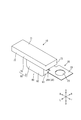
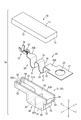
- FIG. 1 is a perspective view of a terminal module according to the first embodiment.
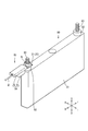
- Perspective view showing a state in which the terminal module is attached to a storage element
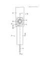
- the top view which shows the state which attached the terminal module to the electrical storage element.
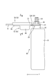
- Side view showing a state in which the terminal module is attached to the storage element
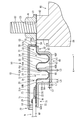
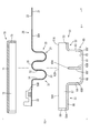
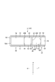
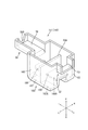
- Top view of voltage detection terminal Top view of lower protector The perspective view which shows the state which attached the terminal module which concerns on Embodiment 2 to the electrical storage element.
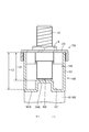
- Sectional view corresponding to the section of FIG. 5 of the terminal module Sectional view corresponding to the section of FIG. 6 of the terminal module
- FIGS. 1 to 10 A first embodiment of the technology disclosed in this specification will be described with reference to FIGS. 1 to 10.
- the present embodiment exemplifies the terminal module 10 connected to the power storage element 80.
- the U direction in FIGS. 1 and 2 is the upper direction
- the D direction is the lower direction
- the R direction is the right direction
- the L direction is the left direction.
- the F direction in FIGS. 1 and 2 will be described as the front and the B direction will be described as the rear.
- the electricity storage element 80 has a flat, substantially rectangular parallelepiped element body 81 in which an electricity storage element (not shown) is housed.
- the element body 81 has a pair of pedestals 82 at both ends in the front-rear direction, and bolt-shaped electrode terminals 83 protruding upward from the pedestal 82 are provided on the upper surface of the pedestal 82. ..
- the electrode terminal 83 is connected to a voltage detection terminal 20 described later of the terminal module 10. To connect the voltage detection terminal 20 to the electrode terminal 83, the voltage detection terminal 20 is assembled so that the electrode terminal 83 is inserted, and the nut N is tightened in the electrode terminal 83. Then, the electrode terminal 83 and the voltage detection terminal 20 are sandwiched between the nut N and the pedestal portion 82 to be electrically connected.
- the terminal module 10 includes a voltage detection terminal 20 for detecting the voltage of the storage element 80, and a protector 50 that houses a part of the voltage detection terminal 20. There is.
- the voltage detection terminal 20 is formed by processing a conductive metal plate material such as copper, copper alloy, aluminum, aluminum alloy, and stainless steel (SUS) by a press or the like.
- a conductive metal plate material such as copper, copper alloy, aluminum, aluminum alloy, and stainless steel (SUS)
- the voltage detection terminal 20 includes a terminal connecting portion 21 connected to the electrode terminal 83 of the storage element 80, an electric wire connecting portion 22 connected to the end of the electric wire W, and a terminal connecting portion. 21 and the wire connection part 22 and the connection part 30 which connects in the front-back direction.
- the terminal connecting portion 21 has a flat plate shape that is substantially rectangular in a plan view.
- the terminal connecting portion 21 is provided with an electrode insertion hole 23 penetrating in the plate thickness direction. By inserting the electrode terminal 83 of the storage element 80 into the electrode insertion hole 23, the terminal connecting portion 21 is connected to the electrode terminal 83. It can be assembled and electrically connected.
- the wire connecting portion 22 is arranged side by side behind the terminal connecting portion 21 and the connecting portion 30, and has a wire barrel 25 connected to the rear of the connecting portion 30 and an insulation barrel 26 connected to the rear of the wire barrel 25. is doing.
- the wire connecting portion 22 is connected to the end of the electric wire W by crimping the wire barrel 25 to the core wire W1 exposed from the insulating coating W2 at the end of the electric wire W, and crimping the insulation barrel 26 to the insulating coating W2. There is.
- the end of the electric wire W on the side opposite to the side connected to the voltage detection terminal 20 is connected to an ECU (Electronic Control Unit) not shown.
- the ECU has a microcomputer, an electronic element, and the like mounted therein, and has a well-known configuration having a function of detecting the voltage, current, temperature, and the like of the power storage element 80.
- the connecting portion 30 is formed in a plate shape having a uniform width in the front-rear direction, the front end portion 30A of the connecting portion 30 is connected to the rear edge of the terminal connecting portion 21, and the rear end portion 30B is connected to the front edge of the wire connecting portion 22.
- the terminal connection portion 21 and the electric wire connection portion 22 are connected in the front-rear direction by being connected to each other.
- the protector 50 is made of insulating synthetic resin. As shown in FIGS. 5 to 8 and 10, the protector 50 has a lower protector 51 in which the voltage detection terminal 20 is housed from above, and an upper protector 70 assembled to the lower protector 51 from above.
- the lower protector 51 is formed in a generally rectangular shape in plan view that is long in the front-rear direction, and includes a first accommodating portion 52 that accommodates the front end portion 30A of the connecting portion 30, a rear end portion 30B of the connecting portion 30, and the voltage detection terminal 20. It has the 2nd accommodating part 55 which accommodates the electric wire connection part 22.
- the first accommodating portion 52 is configured to include a first mounting wall 53 that is substantially rectangular in a plan view, and a pair of first side walls 54 that are erected on both lateral edges of the first mounting wall 53. And is open in the front-rear direction and upward.
- the front end portion 30A of the connecting portion 30 that extends straight rearward from the rear edge of the terminal connecting portion 21 can be mounted on the first mounting wall 53 from above, and the length of the first mounting wall 53 in the left-right direction can be increased.
- the length dimension is set to be slightly larger than the length dimension of the connecting portion 30 in the left-right direction.
- the second accommodating portion 55 includes a second mounting wall 56 that is substantially rectangular in a plan view, a pair of second side walls 57 that are erected on both lateral edges of the second mounting wall 56, and a second mounting wall.
- the second rear wall 58 is provided continuously with the rear end edge 56 and the rear end edges of the pair of second side walls 57, and is open forward and upward.
- the electric wire connecting portion 22 and the rear end portion 30B of the connecting portion 30 that extends straight forward from the front edge of the electric wire connecting portion 22 can be mounted from above.
- the height position of 56 in the up-down direction is substantially the same as the height position of the first mounting wall 53.
- the substantially same height includes the case where the second mounting wall 56 and the first mounting wall 53 have the same height, and the second mounting wall 56 and the first mounting wall 53 have the same height. Includes cases where the heights are recognized to be approximately the same even if the heights are different.
- the second rear wall 58 is formed with a wire drawing hole 58A for drawing out the electric wire W connected to the wire connecting portion 22 from the upper end of the second rear wall 58 so as to be recessed downward.
- the electric wire W is inserted into the electric wire drawing hole 58A, and the electric wire W is rearward from the electric wire drawing hole 58A. It is designed to be pulled out to.
- the upper protector 70 includes a ceiling wall 71 having a substantially rectangular shape in a plan view, a pair of upper side walls 72 extending downward from left and right ends of the ceiling wall 71, and a ceiling wall 71.
- the upper front wall 73 extends downward from the front end edge.
- the upper protector 70 is formed slightly larger in the front-rear, left-right direction than the lower protector 51.
- the upper front wall 73 has a dimension (length in the vertical direction) extending from the ceiling wall 71 set to be slightly shorter than the height dimension of the first housing portion 52 in the lower protector 51, and the upper protector 70 is lower.
- the insertion opening through which the front end portion 30A of the connecting portion 30 is inserted between the upper front wall 73 and the first mounting wall 53 of the first accommodating portion 52. 59 are formed.
- the connecting portion 30 in the voltage detection terminal 20 has a plurality of liquid drainage portions 31, and the lower protector 51 of the protector 50 has a plurality of liquid storage portions between the first storage portion 52 and the second storage portion 55. It has an accommodating portion 60 for accommodating the cut portion 31.
- the plurality of liquid draining parts 31 are continuous in the front-rear direction so as to connect the front end part 30A of the connecting part 30 and the rear end part 30B of the connecting part 30 in the front-rear direction. There is.
- Each liquid draining portion 31 is formed to have the same width dimension as the front end portion 30A and the rear end portion 30B of the connecting portion 30, and is bent downward from the front end portion 30A and extends downward in the gravity direction.
- the extending portion 32, the bent portion 33 that is folded back in an arc shape from the lower end edge of the first extending portion 32 toward the rear, and the opposite upper end edge of the bent portion 33 with respect to the gravity direction. It has the 2nd extension part 34 extended toward the upper part.
- first extension portion 32 and the second extension portion 34 are in a state of facing each other in the front-rear direction, and the bent portion 33 and the lower end edge that is the extension end portion of the first extension portion 32.
- the lower end edge which is the base end portion of the second extending portion 34 is connected in a bent state.
- a portion where the liquid draining portion 31 is continuous in the front-rear direction is a rear end edge which is a front end portion of the second extending portion 34 in the front liquid draining portion 31 and the first extending portion 32 in the rear liquid draining portion 31.
- the upper end position which is the apex of the connecting part 35 is connected to the upper end edge which is the base end part of the connecting part 35 by the connecting part 35 which is bent in an arc shape. It is set to almost the same position.
- each liquid draining portion 31 of the connecting portion 30 is arranged below the height position of the front end portion 30A and the rear end portion 30B of the connecting portion 30 in the direction of gravity and below the pedestal portion 82 of the element body 81. It is configured to meander up and down along the side surface 82A.
- the accommodating portion 60 is formed in a box shape that is larger in the up-down direction than the first accommodating portion 52 and the second accommodating portion 55. It has a bottom wall 61 that is substantially rectangular in a plan view and has the same width dimension as the width dimension of the first accommodation portion 52 and the second accommodation portion 55 in the left-right direction.
- a pair of side walls 62 is provided upright on both lateral edges of the bottom wall 61, and upper end surfaces 62A of the pair of side walls 62 have a first accommodating portion 52 and a second accommodating portion. It is flush with the upper end surface 51A of 55.
- the accommodating portion 60 is configured to project downward from the first accommodating portion 52 and the second accommodating portion 55, and the accommodating portion 60 is similar to the liquid draining portion 31 of the voltage detection terminal 20 in the element body 81. It is designed to be placed behind (sideways).
- the front wall 63 of the accommodating portion 60 extends downward from the rear end edge of the first mounting wall 53 of the first accommodating portion 52 and is continuous with the front end edge of the bottom wall 61, and the rear wall 64 of the accommodating portion 60 is
- the second accommodation wall 55 extends downward from the front end edge of the second mounting wall 56 and continues to the rear end edge of the bottom wall 61.
- the pair of side walls 62 of the housing portion 60 are connected to the first side wall 54 of the first housing portion 52 and the second side wall 57 of the second housing portion 55 so as to be flush with each other in the front-rear direction.
- the inside of the storage unit 60 is divided into a plurality of individual storage units 65 that individually store the plurality of liquid draining units 31.
- the plurality of individual accommodating portions 65 are arranged side by side so as to be continuous in the front-rear direction.
- the individual accommodation portions 65 adjacent to each other in the front-rear direction are separated from each other by a partition wall 60A extending in the left-right direction on the pair of side walls 62 of the accommodation portion 60.
- the rear wall 65B of the individual accommodating portion 65 arranged is formed, and the front wall 65F of the individual accommodating portion 65 arranged on the rear side is formed.
- the front wall 65F of the foremost individual housing portion 65 of the plurality of individual housing portions 65 constitutes the front wall 63 of the housing portion 60
- the rear wall 65B of the last individual housing portion 65 is the rear wall of the housing portion 60. 64 are configured.
- the side walls 65A on the left and right sides of the individual accommodating portions 65 that are adjacent to each other in the front-rear direction are connected in the front-rear direction to form the side walls 62 on the left and right sides of the accommodating portion 60.
- the bottom wall 61 of the housing portion 60 and the bent portion 33 of the liquid draining portion 31 are shown. And are vertically opposed to each other with a gap dimension L2 smaller than the thickness dimension L1 of the bottom wall 61.
- the front wall 65F of the individual accommodation portion 65 and the first extending portion 32 of the liquid draining portion 31 face each other in the front-rear direction, and the rear wall 65B of the individual accommodation portion 65 and the liquid draining portion.
- the gap dimension L3 between the front wall 65F of the individual accommodating portion 65 and the first extending portion 32 becomes larger than that of the individual accommodating portion 65.
- the first extending portion 32 and the second extending portion 34 are arranged in the individual accommodation portion 65 so as to be smaller than the gap dimension L4 between the wall 65B and the second extending portion 34.
- liquid such as water droplets may adhere to electrode terminals or the like to which the terminal module is connected.
- the temperature of the electrode terminal decreases, dew condensation occurs on the electrode terminal, so that the liquid adheres.
- the liquid adhering to the electrode terminal reaches the electric wire through the voltage detection terminal, the liquid may enter the voltage detector or the ECU through the electric wire and cause a problem.
- the terminal module 10 of the present embodiment has at least one of the voltage detection terminal 20 having the terminal connection portion 21 connected to the electrode terminal 83 and the electric wire connection portion 22 connected to the electric wire W, and at least one of the voltage detection terminals 20.
- the protector 50 has at least one 31, and the protector 50 has an accommodating portion 60 that accommodates the liquid draining portion 31 and stores the liquid that has propagated through the first extending portion 32.
- the liquid attached to the electrode terminal 83 travels from the terminal connecting portion 21 to the first extending portion 32 of the liquid draining portion 31 and from the lower end portion of the first extending portion 32. It falls and is stored in the accommodation unit 60. This can prevent the liquid from reaching the electric wire connecting portion 22. As a result, it is possible to prevent the liquid from penetrating the electric wire W and invading other devices to cause a problem.
- the liquid draining part 31 includes the second extending part 34 extending upward, which is the opposite direction to the downward direction which is the gravity direction, and the extending end edge of the first extending part 32. And a bending portion 33 that connects the lower end edge that is the lower end edge that is the base end portion of the second extending portion 34 in a bent state, and the accommodating portion 60 has a gap between the bending portion 33. It has a bottom wall 61 facing the bent portion 33 in the state of having.
- the liquid that has propagated through the first extending portion 32 is attracted to the gap between the bent portion 33 of the liquid draining portion 31 and the bottom wall 61 of the accommodating portion 60 by surface tension, and the liquid easily stays in the accommodating portion 60. Therefore, it is possible to further suppress the liquid from reaching the electric wire connecting portion 22.
- the electrode terminal 83 of the present embodiment is provided on the element body 81 of the electricity storage element 80, and the first extending portion 32 extends along the side surface 82A of the pedestal portion 82 of the element body 81.
- the length dimension of the first extending portion 32 can be set to be larger than that in the case where the first extending portion is arranged above the element body. That is, since the liquid can be guided to the position away from the electric wire connecting portion 22 by the first extending portion 32, it is possible to further suppress the liquid from reaching the electric wire connecting portion 22.
- the terminal module 10 is attached as compared with the case where the housing portion is arranged above the element body of the power storage element. Further, it is possible to prevent the height dimension of the entire electricity storage device 80 from increasing. That is, it is very effective when the height dimension is limited in the space where the electricity storage element 80 is arranged. Further, in the present embodiment, since the plurality of liquid draining portions 31 are provided between the terminal connecting portion 21 and the electric wire connecting portion 22, it is possible to suppress the liquid from reaching the electric wire connecting portion 22. .
- the storage unit 60 of the present embodiment has the individual storage unit 65 that individually stores the plurality of liquid draining parts 31, the liquid that has dropped from each liquid draining part 31 travels along the bottom wall 61 and is not transferred. It is possible to prevent the liquid draining part 31 from reaching.
- the individual housing portion 65 of the present embodiment has a front wall (first side wall) 65F extending along the first extending portion 32 and a rear wall (second side wall) 65B extending along the second extending portion 34.
- the gap dimension L3 between the first extending portion 32 and the front wall 65F is set smaller than the gap dimension L4 between the second extending portion 34 and the rear wall 65B. ..
- the liquid adhering to the liquid draining part 31 is attracted to the gap between the first extending part 32 and the front wall 65F by the surface tension, and the liquid can be quickly drawn into the individual accommodating part 65.
- the gap dimension L4 between the second extending portion 34 and the rear wall 65B is larger than the gap dimension L3 between the first extending portion 32 and the front wall 65F, the individual accommodating portion 65. It is possible to suppress the liquid drawn into the second extension portion 34 from reaching the electric wire connection portion 22 side.
- the protector 150 according to the second embodiment is different from the protector 50 according to the first embodiment in that the width dimension of the housing portion 60 in the left-right direction is changed, and the configurations, actions, and effects common to the first embodiment are duplicated. The description is omitted. Further, the same reference numerals are used for the same configurations as the first embodiment.
- the accommodating portion 160 of the lower protector 151 of the second embodiment has a liquid reservoir main body 166 extending along the direction in which the terminal connecting portion 21 and the electric wire connecting portion 22 are arranged, and a direction intersecting the extending direction of the liquid reservoir main body 166. And a pair of auxiliary liquid reservoirs 167 projecting from the liquid reservoir body 166 in the orthogonal direction. Further, the upper protector 170 has a shape in which a substantially central portion in the front-rear direction is projected in the left-right direction so as to match the housing portion 160.
- the liquid reservoir body 166 is set to have substantially the same width dimension as the width dimension of the first accommodating portion 52 and the second accommodating portion 55 in the left-right direction. Therefore, the auxiliary liquid reservoir 167 has a form protruding in the left-right direction from the first container 52 and the second container 55.
- the auxiliary liquid reservoir portion 167 projects below the liquid reservoir main body portion 166, and the bottom wall 167A of the auxiliary liquid reservoir portion 167 is It is set at a position one step lower than the bottom wall 166A of 166. Therefore, the vertical depth dimension L5 of the auxiliary liquid reservoir 167 is set larger than the vertical depth dimension L6 of the liquid reservoir body 166. In other words, the internal space of the container 160 of this embodiment, and thus the individual container 165, is larger than that in the case where the auxiliary liquid reservoir is not provided.
- the accommodating portion 160 has the auxiliary liquid reservoir portion 167 protruding in the left-right direction and the vertical direction from the liquid reservoir main body portion 166, as compared with the case where the auxiliary reservoir portion is not provided, A large amount of liquid that drops along the first extending part 32 can be stored in the housing part 160, and it is possible to further suppress liquid from reaching the wire connecting part 22 side along the second extending part 34. You can do it.
- the technology disclosed in this specification is not limited to the embodiments described by the above description and the drawings, and includes various aspects such as the following.
- the terminal connection portion 21 of the voltage detection terminal 20 and the electrode terminal 83 are fastened by the nut N and the pedestal portion 82.
- the configuration is not limited to this, and the terminal connection portion may be configured to be connected to the electrode terminal by laser welding, ultrasonic welding, resistance welding, or the like.
- the voltage detection terminal 20 connected to the electrode terminal 83 is shown as an example.
- the present invention is not limited to this, and the technique disclosed in the present specification may be applied to a bus bar terminal that connects electrode terminals of adjacent power storage elements.
- the voltage detection terminal 20 is connected to the electrode terminal 83 of the storage element 80.
- the configuration is not limited to this, and the voltage detection terminal may be connected to an electrode terminal such as a capacitor.
- the liquid attached to the electrode terminal 83 is a water droplet.
- the liquid that adheres to the electrode terminals may be a liquid other than water drops, such as an electrolytic solution.
- the storage portions 60 and 160 are configured to store the liquid that has flowed down from the liquid draining portion 31.
- the present invention is not limited to this, and the storage portion may be provided with a discharge hole for guiding the liquid flowing down from the liquid draining portion to a safe external area.
- Terminal module 20 Voltage detection terminal (an example of "terminal") 21: terminal connection part 22: electric wire connection part 32: first extension part 31: liquid draining part 33: bent part 34: second extension part 50: protector 60: housing part 61: bottom wall 65: individual housing part 65B : Rear wall (an example of "second side wall") 65F: Front wall (an example of "first side wall”) 80: Electric storage element 81: Element body 83: Electrode terminal 166: Liquid reservoir body 167: Auxiliary liquid reservoir L2: Gap L3: Gap dimension L4 between first extension and first side wall: Second extension Dimension W Between the Portion and the Second Side Wall: Electric Wire
Landscapes
- Chemical & Material Sciences (AREA)
- Chemical Kinetics & Catalysis (AREA)
- Electrochemistry (AREA)
- General Chemical & Material Sciences (AREA)
- Physics & Mathematics (AREA)
- General Physics & Mathematics (AREA)
- Engineering & Computer Science (AREA)
- Power Engineering (AREA)
- Microelectronics & Electronic Packaging (AREA)
- Connection Of Batteries Or Terminals (AREA)
- Electric Double-Layer Capacitors Or The Like (AREA)
- Battery Mounting, Suspending (AREA)
Abstract
本明細書によって開示される端子モジュール10は、電極端子83に接続される端子接続部21と、電線Wに接続される電線接続部22とを有する電圧検出端子20と、電圧検出端子20の少なくとも一部を収容するプロテクタ50とを備え、電圧検出端子20における端子接続部21と電線接続部22との間には、重力方向である下方に向かって延びる第1延出部32を含む液切部31を2つ有しており、プロテクタ50は、液切部31を収容し、第1延出部32を伝う液体を貯留する収容部60を有している構成とした。
Description
本明細書によって開示される技術は、端子モジュールに関する。
例えば、電池の電圧を検知するための電圧検出端子として、特開2012-164591号公報(下記特許文献1)に記載のものが知られている。この電圧検出端子は、電圧検出器やECU(Electronic Control Unit)等から延びる電線の端末に接続されており、電池の電極間を接続するバスバに重ねて接続される。
ところで、電極間を接続するためのバスバには水滴等の液体が付着することがある。例えば、車両の停車時等にバスバの温度が低下すると、バスバに結露が発生することがある。バスバに付着した水滴等の液体は、電圧検出端子を介して電線に至ると、液体が電線を通じて電圧検出器やECUに浸入し、不具合が生じてしまう。
本明細書では、電線に液体が至ることを抑制する技術を開示する。
本明細書によって開示される技術は、電極端子に接続される端子接続部と、電線に接続される電線接続部とを有する端子と、前記端子の少なくとも一部を収容するプロテクタとを備え、前記端子における前記端子接続部と前記電線接続部との間には、重力方向に向かって延びる第1延出部を含む液切部を少なくとも1つ有しており、前記プロテクタは、前記液切部を収容する収容部を有している構成とした。
このような構成の端子モジュールによると、端子接続部に付着した液体は、液切部の第1延出部を伝って第1延出部の下端部から収容部に貯留されるため、液体が電線接続部に至ることを抑制することができる。これにより、液体が電線に至って、他の機器などに不具合が生じることを抑制することができる。
本明細書によって開示される端子モジュールは、以下の構成としてもよい。
前記電極端子は蓄電素子の素子本体に設けられており、前記第1延出部は、前記素子本体の側面に沿って延びている構成としてもよい。
前記電極端子は蓄電素子の素子本体に設けられており、前記第1延出部は、前記素子本体の側面に沿って延びている構成としてもよい。
このような構成によると、液切部の第1延出部が素子本体の側面に沿って延びているから、例えば、第1延出部が素子本体の上部に配置される場合に比べて、第1延出部の長さ寸法を大きく設定することができる。つまり、液体を電線接続部から離れた位置まで第1延出部によって導くことができるから、液体が電線接続部に至ることをさらに抑制することができる。
前記電極端子は前記蓄電素子の素子本体に設けられており、前記収容部は、前記素子本体の側方に配置されている構成としてもよい。
このような構成によると、収容部が素子本体の側方に配置されているから、例えば、収容部が蓄電素子の素子本体の上部に配置される場合に比べて、端子モジュールが取り付けられた蓄電素子全体の高さ寸法が大きくなることを抑制することができる。
このような構成によると、収容部が素子本体の側方に配置されているから、例えば、収容部が蓄電素子の素子本体の上部に配置される場合に比べて、端子モジュールが取り付けられた蓄電素子全体の高さ寸法が大きくなることを抑制することができる。
前記液切部は、重力方向に対して反対方向に向かって延びる第2延出部と、前記第1延出部の延出端部と前記第2延出部の基端部との間を屈曲した状態で繋ぐ屈曲部とをさらに有し、前記収容部は、前記屈曲部との間に隙間を有した状態で前記屈曲部と対向する底壁を有している構成としてもよい。
このような構成によると、第1延出部を伝った液体が液切部の屈曲部と収容部の底壁との間の隙間に表面張力によって引きつけられ、液体が収容部に留まり易くなるから、液体が電線接続部に至ることをさらに抑制することができる。
前記端子接続部と前記電線接続部との間には、複数の前記液切部が設けられており、前記収容部は、前記複数の液切部を個別に収容する個別収容部を有している構成としてもよい。
このような構成によると、端子接続部と電線接続部との間には、複数の液切部が設けられているから、液体が電線接続部に至ることを抑制することができる。
このような構成によると、端子接続部と電線接続部との間には、複数の液切部が設けられているから、液体が電線接続部に至ることを抑制することができる。
ところで、例えば、複数の液切部が1つの収容部に一括して収容されている場合には、端子接続部に最も近い液切部から収容部内に落下した液体が底壁を伝って電線接続部に最も近い液切部に至ってしまうことが懸念される。ところが、このような構成によると、各液切部が個別収容部に個別に収容されているから、各液切部から落下した液体が底壁を伝って他の液切部に至ることを防ぐことができる。
前記個別収容部は、前記第1延出部に沿って延びる第1側壁と、前記第2延出部に沿って延びる第2側壁とを有しており、前記第1延出部と前記第1側壁との間の隙間寸法は、前記第2延出部と第2側壁との間の隙間寸法よりも小さく設定されている構成としてもよい。
このような構成によると、液切部に付着した液体が第1延出部と第1側壁との間の隙間に表面張力によって引き寄せられ、液体を速やかに個別収容部内に引き込むことができる。また、第2延出部と第2側壁との間の隙間寸法は、第1延出部と第1側壁との間の隙間寸法よりも大きくなっているから、第2延出部と第2側壁との間の隙間には表面張力が生じ難くなり、個別収容部内に引き込まれた液体が第2延出部を伝って電線接続部側に至ることを抑制することができる。
前記端子接続部と前記電線接続部とは並んで配置されており、前記収容部は、前記端子接続部と前記電線接続部との並び方向に沿って延びる液溜本体部と、前記液溜本体部の延び方向と交差する方向に前記液溜本体部から突出する補助液溜部とを有している構成としてもよい。
このような構成によると、液切部から落下する液体の収容領域を大きくすることができるから、収容部に溜まった液体が第2延出部を伝って電線接続部側に至ることを抑制できる。これにより、液体が電線に至って、他の機器などに不具合が生じることを抑制することができる。
前記補助液溜部の深さ寸法は、前記液溜本体部の深さ寸法よりも大きく設定されている構成としてもよい。
このような構成によると、液切部から落下する液体の収容領域を大きくすることができる。また、端子が配置される液溜本体部に補助液溜部内に貯留された液体が及ぶことを抑制することができる。これにより、収容部に溜まった液体が第2延出部を伝って電線接続部側に至ることをさらに抑制することができ、液体が電線に至って、他の機器などに不具合が生じることを抑制することができる。
このような構成によると、液切部から落下する液体の収容領域を大きくすることができる。また、端子が配置される液溜本体部に補助液溜部内に貯留された液体が及ぶことを抑制することができる。これにより、収容部に溜まった液体が第2延出部を伝って電線接続部側に至ることをさらに抑制することができ、液体が電線に至って、他の機器などに不具合が生じることを抑制することができる。
本明細書によって開示される技術によれば、電線に液体が至ることを抑制することができる。
<実施形態1>
本明細書に開示された技術における実施形態1について図1から図10を参照して説明する。
本実施形態は、蓄電素子80に接続される端子モジュール10を例示している。なお、以下の説明において、図1および図2におけるU方向を上方、D方向を下方とし、R方向を右方、L方向を左方とする。また、図1および図2におけるF方向を前方、B方向を後方として説明する。
本明細書に開示された技術における実施形態1について図1から図10を参照して説明する。
本実施形態は、蓄電素子80に接続される端子モジュール10を例示している。なお、以下の説明において、図1および図2におけるU方向を上方、D方向を下方とし、R方向を右方、L方向を左方とする。また、図1および図2におけるF方向を前方、B方向を後方として説明する。
蓄電素子80は、図2から図5に示すように、図示しない蓄電要素が収容された扁平な略直方体状の素子本体81を有している。素子本体81は、前後方向両端部に一対の台座部82を有しており、台座部82の上面には、台座部82から上方に向けて突出するボルト状の電極端子83が設けられている。電極端子83には、端子モジュール10の後述する電圧検出端子20が接続されるようになっている。電極端子83に電圧検出端子20を接続するには、電圧検出端子20に電極端子83を挿通するように組み付け、電極端子83にナットNを締め込む。すると、電極端子83と電圧検出端子20とがナットNと台座部82とに挟持されて電気的に接続されるようになっている。
端子モジュール10は、図1から図5に示すように、蓄電素子80の電圧を検出するための電圧検出端子20と、電圧検出端子20の一部を収容するプロテクタ50とを備えて構成されている。
電圧検出端子20は、例えば銅、銅合金、アルミニウム、アルミニウム合金、ステンレス鋼(SUS)等の導電性を有する金属板材をプレスなどによって加工することによって形成されている。
電圧検出端子20は、図7から図9に示すように、蓄電素子80の電極端子83と接続される端子接続部21と、電線Wの端末に接続される電線接続部22と、端子接続部21と電線接続部22とを前後方向に繋ぐ繋ぎ部30とを備えて構成されている。
端子接続部21は、平面視略矩形の平板状をなしている。端子接続部21には、板厚方向に貫通する電極挿通孔23が設けられており、電極挿通孔23に蓄電素子80の電極端子83を挿通することにより、端子接続部21を電極端子83に組み付けて電気的に接続することができるようになっている。
電線接続部22は、端子接続部21および繋ぎ部30の後方に並んで配置されており、繋ぎ部30の後方に連なるワイヤバレル25と、ワイヤバレル25の後方に連なるインシュレーションバレル26とを有している。電線接続部22は、ワイヤバレル25が電線Wの端末において絶縁被覆W2から露出した芯線W1に圧着され、インシュレーションバレル26が絶縁被覆W2に圧着されることにより、電線Wの端末に接続されている。
電線Wは、電圧検出端子20に接続される側とは反対側の端部が図示しないECU(Electronic Control Unit)に接続される。ECUは、マイクロコンピュータ、電子素子等が搭載されたものであって、蓄電素子80の電圧・電流・温度等の検出などを行うための機能を備えた周知の構成である。
繋ぎ部30は、前後方向に等幅の板状に形成されており、繋ぎ部30の前端部30Aが端子接続部21の後縁に連なると共に、後端部30Bが電線接続部22の前縁に連なることにより、端子接続部21と電線接続部22との間を前後方向に繋ぐ形態とされている。
プロテクタ50は、絶縁性の合成樹脂によって形成されている。プロテクタ50は、図5から図8および図10に示すように、電圧検出端子20が上方から収容されるロアプロテクタ51と、ロアプロテクタ51に上方から組み付けられるアッパプロテクタ70とを有する。
ロアプロテクタ51は、前後に長い平面視略矩形状に形成されており、繋ぎ部30の前端部30Aを収容する第1収容部52と、繋ぎ部30の後端部30Bおよび電圧検出端子20の電線接続部22を収容する第2収容部55とを有している。
第1収容部52は、平面視略矩形状の第1載置壁53と、第1載置壁53の左右方向両側縁に立設された一対の第1側壁54とを備えて構成されており、前後方向および上方に開口した形態とされている。
第1載置壁53には、端子接続部21の後縁から後方に真っ直ぐ延びる繋ぎ部30の前端部30Aが上方から載置可能とされており、第1載置壁53の左右方向の長さ寸法は、繋ぎ部30の左右方向の長さ寸法よりもやや大きく設定されている。
第2収容部55は、平面視略矩形状の第2載置壁56と、第2載置壁56の左右方向両側縁に立設された一対の第2側壁57と、第2載置壁56の後端縁および一対の第2側壁57の後端縁に連なって設けられた第2後壁58とを備えて構成されており、前方および上方に開口した形態とされている。
第2載置壁56には、電線接続部22および電線接続部22の前縁から前方に真っ直ぐ延びる繋ぎ部30の後端部30Bが上方から載置可能とされており、第2載置壁56の上下方向の高さ位置は、第1載置壁53の高さ位置と実質的に同じ高さ位置とされている。なお、実質的に同じ高さとは、第2載置壁56と第1載置壁53とが同じ高さである場合を含むと共に、第2載置壁56と第1載置壁53とが異なる高さであっても略同じと認められる場合を含む。
第2後壁58には、電線接続部22に接続された電線Wを引き出す電線引出孔58Aが第2後壁58の上端から下方に向かって凹んで形成されている。電線引出孔58Aには、第2載置壁56に繋ぎ部30の後端部30Bおよび電線接続部22が載置された際に、電線Wが挿通され、電線Wが電線引出孔58Aから後方に引き出されるようになっている。
アッパプロテクタ70は、図6および図7に示すように、平面視略矩形状をなす天井壁71と、天井壁71の左右方向両端縁から下方に延びる一対の上側壁72と、天井壁71の前端縁から下方に延びる上前壁73とを備えて構成されている。アッパプロテクタ70は、ロアプロテクタ51よりも前後左右方向にやや大きく形成されており、アッパプロテクタ70がロアプロテクタ51に組み付けられると、電圧検出端子20の繋ぎ部30および電線接続部22と共にロアプロテクタ51を上方から完全に覆うようになっている。
上前壁73は、天井壁71からの延出寸法(上下方向の長さ寸法)がロアプロテクタ51における第1収容部52の高さ寸法よりもやや短く設定されており、アッパプロテクタ70がロアプロテクタ51に組み付けられた状態では、図5に示すように、上前壁73と第1収容部52の第1載置壁53との間に繋ぎ部30の前端部30Aが挿通される挿通開口59が形成されるようになっている。
さて、電圧検出端子20における繋ぎ部30は、複数の液切部31を有しており、プロテクタ50のロアプロテクタ51は、第1収容部52と第2収容部55との間に複数の液切部31を収容する収容部60を有している。
複数の液切部31は、図7から図9に示すように、繋ぎ部30の前端部30Aと繋ぎ部30の後端部30Bとを前後方向に繋ぐように前後方向に2つに連なっている。
各液切部31は、繋ぎ部30の前端部30Aおよび後端部30Bと同一の幅寸法に形成されており、前端部30Aから下方に屈曲されて重力方向である下方に向かって延びる第1延出部32と、第1延出部32の下端縁から後方に向けて円弧状に折り返された屈曲部33と、屈曲部33の後側の上端縁から重力方向に対して反対方向である上方に向かって延びる第2延出部34とを有している。
言い換えると、第1延出部32と第2延出部34とは前後方向に対向した状態となっており、屈曲部33は、第1延出部32の延出端部である下端縁と第2延出部34の基端部である下端縁との間を屈曲した状態で繋いでいる。
また、液切部31が前後方向に連なる部分は、前側の液切部31における第2延出部34の先端部である後端縁と後側の液切部31における第1延出部32の基端部である上端縁とを円弧状に屈曲した連結部35によって連結されており、連結部35の頂点である上端位置は、繋ぎ部30の前端部30Aおよび後端部30Bの高さ位置とほぼ同じに設定されている。
また、第1延出部32および第2延出部34は、図5に示すように、端子接続部21が蓄電素子80の電極端子83に接続された状態では、素子本体81の台座部82の後方(側方)において台座部82の側面82Aに沿うように下方に延びた状態に配置される。
したがって、繋ぎ部30における各液切部31は、繋ぎ部30の前端部30Aおよび後端部30Bの高さ位置よりも重力方向である下方に配置された状態で素子本体81における台座部82の側面82Aに沿うように上下に蛇行する形態とされている。
したがって、繋ぎ部30における各液切部31は、繋ぎ部30の前端部30Aおよび後端部30Bの高さ位置よりも重力方向である下方に配置された状態で素子本体81における台座部82の側面82Aに沿うように上下に蛇行する形態とされている。
一方、収容部60は、図7、図8および図10に示すように、第1収容部52および第2収容部55よりも上下方向に大きい箱形状に形成されており、収容部60は、第1収容部52および第2収容部55の左右方向の幅寸法と同一の幅寸法なす平面視略矩形状の底壁61を有している。
底壁61の左右方向の両側縁には、図6に示すように、一対の側壁62が立設されており、一対の側壁62における上端面62Aは、第1収容部52および第2収容部55の上端面51Aと面一状態とされている。
したがって、収容部60は、第1収容部52および第2収容部55よりも下方に突出した形態とされ、収容部60は、電圧検出端子20の液切部31と同様に、素子本体81の後方(側方)に配置されるようになっている。
収容部60の前壁63は、第1収容部52の第1載置壁53の後端縁から下方に延びて底壁61の前端縁に連なっており、収容部60の後壁64は、第2収容部55の第2載置壁56の前端縁から下方に延びて底壁61の後端縁に連なっている。また、収容部60の一対の側壁62は、第1収容部52の第1側壁54と第2収容部55の第2側壁57とに前後方向に面一状に連なっている。
収容部60の内部は、複数の液切部31を個別に収容する複数の個別収容部65に区切られている。
複数の個別収容部65は、前後方向に連なるように並んで配置されている。前後に隣り合う個別収容部65は、収容部60の一対の側壁62を左右方向に延びる仕切壁60Aによって区切られており、前後に隣り合う個別収容部65間を区切る仕切壁60Aは、前側に配される個別収容部65の後壁65Bを構成すると共に、後側に配される個別収容部65の前壁65Fを構成している。
複数の個別収容部65は、前後方向に連なるように並んで配置されている。前後に隣り合う個別収容部65は、収容部60の一対の側壁62を左右方向に延びる仕切壁60Aによって区切られており、前後に隣り合う個別収容部65間を区切る仕切壁60Aは、前側に配される個別収容部65の後壁65Bを構成すると共に、後側に配される個別収容部65の前壁65Fを構成している。
また、複数の個別収容部65のうちの最前の個別収容部65の前壁65Fは収容部60の前壁63を構成し、最後の個別収容部65の後壁65Bは収容部60の後壁64を構成している。そして、前後に隣り合う個別収容部65の左右方向両側の側壁65Aは、前後方向に連なることにより、収容部60の左右方向両側の側壁62を構成している。
また、繋ぎ部30における液切部31が個別収容部65に個別に収容された状態では、図5および図6に示すように、収容部60の底壁61と液切部31の屈曲部33とが、底壁61の厚さ寸法L1よりも小さい隙間寸法L2を有した状態で上下方向に対向する。また、図5に示すように、個別収容部65の前壁65Fと液切部31の第1延出部32とが前後方向に対向すると共に、個別収容部65の後壁65Bと液切部31の第2延出部34とが前後方向に対向した状態となって、個別収容部65の前壁65Fと第1延出部32との間の隙間寸法L3が、個別収容部65の後壁65Bと第2延出部34との間の隙間寸法L4よりも小さくなるように個別収容部65内に第1延出部32と第2延出部34とが配置されるようになっている。
本実施形態は、以上のような構成であって、続いて、端子モジュール10の作用および効果について説明する。
一般に、端子モジュールが接続される電極端子などには、水滴等の液体が付着することがある。例えば、電極端子の温度が低下すると、電極端子に結露が発生することにより、液体が付着する。電極端子に付着した液体は、電圧検出端子を介して電線に至ると、液体が電線を通じて電圧検出器やECUに浸入し不具合が生じることが懸念される。
一般に、端子モジュールが接続される電極端子などには、水滴等の液体が付着することがある。例えば、電極端子の温度が低下すると、電極端子に結露が発生することにより、液体が付着する。電極端子に付着した液体は、電圧検出端子を介して電線に至ると、液体が電線を通じて電圧検出器やECUに浸入し不具合が生じることが懸念される。
そこで、本発明者らは、上記の課題を解決するため、鋭意検討を行った結果、本実施形態の構成を見出した。すなわち、本実施形態の端子モジュール10は、電極端子83に接続される端子接続部21と、電線Wに接続される電線接続部22とを有する電圧検出端子20と、電圧検出端子20の少なくとも一部を収容するプロテクタ50とを備え、電圧検出端子20における端子接続部21と電線接続部22との間には、重力方向である下方に向かって延びる第1延出部32を含む液切部31を少なくとも1つ有しており、プロテクタ50は、液切部31を収容し、第1延出部32を伝う液体を貯留する収容部60を有している。
すなわち、本実施形態の端子モジュール10によると、電極端子83に付着した液体は、端子接続部21から液切部31の第1延出部32を伝って第1延出部32の下端部から落下して収容部60に貯留される。これにより、液体が電線接続部22に至ることを抑制することができる。
ひいては、液体が電線Wを伝って他の機器など浸入して不具合が生じることを抑制することができる。
ひいては、液体が電線Wを伝って他の機器など浸入して不具合が生じることを抑制することができる。
また、本実施形態によると、液切部31は、重力方向である下方に対して反対方向である上方に向かって延びる第2延出部34と、第1延出部32の延出端縁である下端縁と第2延出部34の基端部である下端縁との間を屈曲した状態で繋ぐ屈曲部33とをさらに有し、収容部60は、屈曲部33との間に隙間を有した状態で屈曲部33と対向する底壁61を有している。
つまり、第1延出部32を伝った液体が液切部31の屈曲部33と収容部60の底壁61との間の隙間に表面張力によって引きつけられ、液体が収容部60に留まり易くなるから、液体が電線接続部22に至ることをさらに抑制することができる。
また、本実施形態の電極端子83は蓄電素子80の素子本体81に設けられており、第1延出部32は、素子本体81における台座部82の側面82Aに沿って延びているから、例えば、第1延出部が素子本体の上部に配置される場合に比べて、第1延出部32の長さ寸法を大きく設定することができる。つまり、液体を電線接続部22から離れた位置まで第1延出部32によって導くことができるから、液体が電線接続部22に至ることをさらに抑制することができる。
さらに、収容部60は、素子本体81の後方(側方)に配置されているから、例えば、収容部が蓄電素子の素子本体の上部に配置される場合に比べて、端子モジュール10が取り付けられた蓄電素子80全体の高さ寸法が大きくなることを抑制することができる。つまり、蓄電素子80を配置するスペースにおいて高さ寸法に制限がある場合には、非常に有効である。
また、本実施形態は、端子接続部21と電線接続部22との間には、複数の液切部31が設けられているから、液体が電線接続部22に至ることを抑制することができる。
また、本実施形態は、端子接続部21と電線接続部22との間には、複数の液切部31が設けられているから、液体が電線接続部22に至ることを抑制することができる。
ところで、例えば、複数の液切部が1つの収容部に一括して収容されている場合には、端子接続部に最も近い液切部から収容部内に落下した液体が底壁を伝って電線接続部に最も近い液切部から電線接続部に至ってしまうことが懸念される。
ところが、本実施形態の収容部60は、複数の液切部31を個別に収容する個別収容部65を有しているから、各液切部31から落下した液体が底壁61を伝って他の液切部31に至ることを防ぐことができる。
ところが、本実施形態の収容部60は、複数の液切部31を個別に収容する個別収容部65を有しているから、各液切部31から落下した液体が底壁61を伝って他の液切部31に至ることを防ぐことができる。
さらに、本実施形態の個別収容部65は、第1延出部32に沿って延びる前壁(第1側壁)65Fと、第2延出部34に沿って延びる後壁(第2側壁)65Bとを有しており、第1延出部32と前壁65Fとの間の隙間寸法L3は、第2延出部34と後壁65Bとの間の隙間寸法L4よりも小さく設定されている。
つまり、液切部31に付着した液体は、第1延出部32と前壁65Fとの間の隙間に表面張力によって引き寄せられ、液体を速やかに個別収容部65内に引き込むことができる。一方、第2延出部34と後壁65Bとの間の隙間寸法L4は、第1延出部32と前壁65Fとの間の隙間寸法L3よりも大きくなっているから、個別収容部65内に引き込まれた液体が第2延出部34を伝って電線接続部22側に至ることを抑制することができる。
<実施形態2>
次に、実施形態2について図11から図15を参照して説明する。
実施形態2のプロテクタ150は、実施形態1におけるプロテクタ50の収容部60の左右方向の幅寸法を変更したものであって、実施形態1と共通する構成、作用、および効果については重複するため、その説明を省略する。また、実施形態1と同じ構成については同一の符号を用いるものとする。
次に、実施形態2について図11から図15を参照して説明する。
実施形態2のプロテクタ150は、実施形態1におけるプロテクタ50の収容部60の左右方向の幅寸法を変更したものであって、実施形態1と共通する構成、作用、および効果については重複するため、その説明を省略する。また、実施形態1と同じ構成については同一の符号を用いるものとする。
第2実施形態のロアプロテクタ151の収容部160は、端子接続部21と電線接続部22との並び方向に沿って延びる液溜本体部166と、液溜本体部166の延び方向と交差する方向である直交する方向に液溜本体部166から突出する一対の補助液溜部167とを有している。
また、アッパプロテクタ170は、収容部160に合わせて前後方向略中央部が左右方向に突出した形態とされている。
また、アッパプロテクタ170は、収容部160に合わせて前後方向略中央部が左右方向に突出した形態とされている。
液溜本体部166は、図13から図15に示すように、第1収容部52および第2収容部55の左右方向の幅寸法とほぼ同じ幅寸法に設定されている。したがって、補助液溜部167は、第1収容部52および第2収容部55よりも左右方向に突出した形態とされている。
また、補助液溜部167は、図11、図13および図14に示すように、液溜本体部166よりも下方に突出しており、補助液溜部167の底壁167Aは、液溜本体部166の底壁166Aよりも一段下がった位置に設定されている。したがって、補助液溜部167の上下方向の深さ寸法L5は、液溜本体部166の上下方向の深さ寸法L6よりも大きく設定されている。
つまり、本実施形態の収容部160、ひいては個別収容部165の内部空間は、補助液溜部を設けない場合に比べて大きくなっている。
つまり、本実施形態の収容部160、ひいては個別収容部165の内部空間は、補助液溜部を設けない場合に比べて大きくなっている。
すなわち、本実施形態によると、収容部160が液溜本体部166よりも左右方向および上下方向に突出した補助液溜部167を有しているから、補助溜部を設けない場合に比べて、第1延出部32を伝って落下する液体を収容部160内に多く貯留することができると共に、液体が第2延出部34を伝って電線接続部22側に至ることをさらに抑制することができるようになっている。
<他の実施形態>
本明細書で開示される技術は上記記述及び図面によって説明した実施形態に限定されるものではなく、例えば次のような種々の態様も含まれる。
(1)上記実施形態では、電圧検出端子20の端子接続部21と電極端子83とをナットNと台座部82とによって締結する構成にした。しかしながら、これに限らず、端子接続部は、レーザー溶接、超音波溶接、抵抗溶接などによって電極端子に接続する構成にしてもよい。
本明細書で開示される技術は上記記述及び図面によって説明した実施形態に限定されるものではなく、例えば次のような種々の態様も含まれる。
(1)上記実施形態では、電圧検出端子20の端子接続部21と電極端子83とをナットNと台座部82とによって締結する構成にした。しかしながら、これに限らず、端子接続部は、レーザー溶接、超音波溶接、抵抗溶接などによって電極端子に接続する構成にしてもよい。
(2)上記実施形態では、電極端子83に接続される電圧検出端子20を一例として示した。しかしながら、これに限らず、隣り合う蓄電素子の電極端子同士を接続するバスバ端子に本明細書で開示した技術を適用してもよい。
(3)上記実施形態では、電圧検出端子20が蓄電素子80の電極端子83に接続される構成とした。しかしながら、これに限らず、電圧検出端子をキャパシタなどの電極端子に接続する構成にしてもよい。
(4)上記実施形態では、電極端子83に付着する液体を水滴とした。しかしながら、これに限らず、電極端子に付着する液体は、電解液など水滴以外の液体であってもよい。
(5)上記実施形態では、収容部60,160には、液切部31から流れ落ちた液体が貯留される構成とした。しかしながら、これに限らず、収容部には、液切部から流れ落ちた液体を安全な外部領域へ誘導するための排出孔を設けてもよい。
(5)上記実施形態では、収容部60,160には、液切部31から流れ落ちた液体が貯留される構成とした。しかしながら、これに限らず、収容部には、液切部から流れ落ちた液体を安全な外部領域へ誘導するための排出孔を設けてもよい。
10:端子モジュール
20:電圧検出端子(「端子」の一例)
21:端子接続部
22:電線接続部
32:第1延出部
31:液切部
33:屈曲部
34:第2延出部
50:プロテクタ
60:収容部
61:底壁
65:個別収容部
65B:後壁(「第2側壁」の一例)
65F:前壁(「第1側壁」の一例)
80:蓄電素子
81:素子本体
83:電極端子
166:液溜本体部
167:補助液溜部
L2:隙間
L3:第1延出部と第1側壁との間の隙間寸法
L4:第2延出部と第2側壁との間の隙間寸法
W:電線
20:電圧検出端子(「端子」の一例)
21:端子接続部
22:電線接続部
32:第1延出部
31:液切部
33:屈曲部
34:第2延出部
50:プロテクタ
60:収容部
61:底壁
65:個別収容部
65B:後壁(「第2側壁」の一例)
65F:前壁(「第1側壁」の一例)
80:蓄電素子
81:素子本体
83:電極端子
166:液溜本体部
167:補助液溜部
L2:隙間
L3:第1延出部と第1側壁との間の隙間寸法
L4:第2延出部と第2側壁との間の隙間寸法
W:電線
Claims (8)
- 電極端子に接続される端子接続部と、電線に接続される電線接続部とを有する端子と、
前記端子の少なくとも一部を収容するプロテクタとを備え、
前記端子における前記端子接続部と前記電線接続部との間には、重力方向に向かって延びる第1延出部を含む液切部を少なくとも1つ有しており、
前記プロテクタは、前記液切部を収容する収容部を有している端子モジュール。 - 前記電極端子は蓄電素子の素子本体に設けられており、
前記第1延出部は、前記素子本体の側面に沿って延びている請求項1に記載の端子モジュール。 - 前記電極端子は蓄電素子の素子本体に設けられており、
前記収容部は、前記素子本体の側方に配置されている請求項1または請求項2に記載の端子モジュール。 - 前記液切部は、重力方向に対して反対方向に向かって延びる第2延出部と、前記第1延出部の延出端部と前記第2延出部の基端部との間を屈曲した状態で繋ぐ屈曲部とをさらに有し、
前記収容部は、前記屈曲部との間に隙間を有した状態で前記屈曲部と対向する底壁を有している請求項1から請求項3のいずれか一項に記載の端子モジュール。 - 前記端子接続部と前記電線接続部との間には、複数の前記液切部が設けられており、
前記収容部は、前記複数の液切部を個別に収容する個別収容部を有している請求項4に記載の端子モジュール。 - 前記個別収容部は、前記第1延出部に沿って延びる第1側壁と、前記第2延出部に沿って延びる第2側壁とを有しており、前記第1延出部と前記第1側壁との間の隙間寸法は、前記第2延出部と第2側壁との間の隙間寸法よりも小さく設定されている請求項5に記載の端子モジュール。
- 前記端子接続部と前記電線接続部とは並んで配置されており、
前記収容部は、前記端子接続部と前記電線接続部との並び方向に沿って延びる液溜本体部と、前記液溜本体部の延び方向と交差する方向に前記液溜本体部から突出する補助液溜部とを有している請求項1から請求項6のいずれか一項に記載の端子モジュール。 - 前記補助液溜部の深さ寸法は、前記液溜本体部の深さ寸法よりも大きく設定されている請求項7に記載の端子モジュール。
Priority Applications (2)
| Application Number | Priority Date | Filing Date | Title |
|---|---|---|---|
| US17/295,285 US11982712B2 (en) | 2018-11-22 | 2019-11-01 | Terminal module |
| CN201980074024.2A CN112970082B (zh) | 2018-11-22 | 2019-11-01 | 端子模块 |
Applications Claiming Priority (2)
| Application Number | Priority Date | Filing Date | Title |
|---|---|---|---|
| JP2018-219042 | 2018-11-22 | ||
| JP2018219042A JP6981394B2 (ja) | 2018-11-22 | 2018-11-22 | 端子モジュール |
Publications (1)
| Publication Number | Publication Date |
|---|---|
| WO2020105398A1 true WO2020105398A1 (ja) | 2020-05-28 |
Family
ID=70773174
Family Applications (1)
| Application Number | Title | Priority Date | Filing Date |
|---|---|---|---|
| PCT/JP2019/042998 Ceased WO2020105398A1 (ja) | 2018-11-22 | 2019-11-01 | 端子モジュール |
Country Status (4)
| Country | Link |
|---|---|
| US (1) | US11982712B2 (ja) |
| JP (1) | JP6981394B2 (ja) |
| CN (1) | CN112970082B (ja) |
| WO (1) | WO2020105398A1 (ja) |
Families Citing this family (3)
| Publication number | Priority date | Publication date | Assignee | Title |
|---|---|---|---|---|
| JP7531781B2 (ja) | 2020-05-19 | 2024-08-13 | 株式会社リコー | p型半導性を有する金属酸化物粒子、それを用いた電子デバイス及び電子デバイスの製造方法、並びに画像形成装置 |
| JP7587685B2 (ja) * | 2021-04-07 | 2024-11-20 | ビークルエナジージャパン株式会社 | 組電池 |
| JP7601704B2 (ja) * | 2021-04-30 | 2024-12-17 | 矢崎総業株式会社 | 電圧検知ユニット |
Citations (5)
| Publication number | Priority date | Publication date | Assignee | Title |
|---|---|---|---|---|
| JP2015005473A (ja) * | 2013-06-24 | 2015-01-08 | 住友電気工業株式会社 | ブスバーおよびブスバーの製造方法 |
| JP2015035322A (ja) * | 2013-08-08 | 2015-02-19 | 矢崎総業株式会社 | バスバモジュール |
| JP2017059468A (ja) * | 2015-09-18 | 2017-03-23 | 株式会社オートネットワーク技術研究所 | 端子付き電線、及び配線モジュール |
| WO2017047371A1 (ja) * | 2015-09-16 | 2017-03-23 | 株式会社オートネットワーク技術研究所 | 端子及び配線モジュール |
| WO2017047372A1 (ja) * | 2015-09-16 | 2017-03-23 | 株式会社オートネットワーク技術研究所 | 端子及び配線モジュール |
Family Cites Families (5)
| Publication number | Priority date | Publication date | Assignee | Title |
|---|---|---|---|---|
| JP3613445B2 (ja) * | 1999-05-18 | 2005-01-26 | 矢崎総業株式会社 | バッテリ接続プレート |
| JP2010257764A (ja) * | 2009-04-24 | 2010-11-11 | Toyota Motor Corp | 端子および電池 |
| JP2010257762A (ja) * | 2009-04-24 | 2010-11-11 | Toyota Motor Corp | 端子および電池 |
| JP5462813B2 (ja) | 2011-02-09 | 2014-04-02 | 矢崎総業株式会社 | バスバモジュール |
| JP6297922B2 (ja) * | 2014-05-23 | 2018-03-20 | 株式会社デンソー | 電池パック |
-
2018
- 2018-11-22 JP JP2018219042A patent/JP6981394B2/ja active Active
-
2019
- 2019-11-01 US US17/295,285 patent/US11982712B2/en active Active
- 2019-11-01 CN CN201980074024.2A patent/CN112970082B/zh active Active
- 2019-11-01 WO PCT/JP2019/042998 patent/WO2020105398A1/ja not_active Ceased
Patent Citations (5)
| Publication number | Priority date | Publication date | Assignee | Title |
|---|---|---|---|---|
| JP2015005473A (ja) * | 2013-06-24 | 2015-01-08 | 住友電気工業株式会社 | ブスバーおよびブスバーの製造方法 |
| JP2015035322A (ja) * | 2013-08-08 | 2015-02-19 | 矢崎総業株式会社 | バスバモジュール |
| WO2017047371A1 (ja) * | 2015-09-16 | 2017-03-23 | 株式会社オートネットワーク技術研究所 | 端子及び配線モジュール |
| WO2017047372A1 (ja) * | 2015-09-16 | 2017-03-23 | 株式会社オートネットワーク技術研究所 | 端子及び配線モジュール |
| JP2017059468A (ja) * | 2015-09-18 | 2017-03-23 | 株式会社オートネットワーク技術研究所 | 端子付き電線、及び配線モジュール |
Also Published As
| Publication number | Publication date |
|---|---|
| JP2020087650A (ja) | 2020-06-04 |
| US20220013871A1 (en) | 2022-01-13 |
| CN112970082B (zh) | 2023-06-13 |
| CN112970082A (zh) | 2021-06-15 |
| US11982712B2 (en) | 2024-05-14 |
| JP6981394B2 (ja) | 2021-12-15 |
Similar Documents
| Publication | Publication Date | Title |
|---|---|---|
| JP6372620B2 (ja) | 端子及び配線モジュール | |
| JP7307213B2 (ja) | 電池モジュール | |
| JP5609825B2 (ja) | 電池接続ユニット及び電源装置 | |
| JP4445819B2 (ja) | 電気接続箱 | |
| JP2020087650A (ja) | 端子モジュール | |
| JP6508345B2 (ja) | 端子及び配線モジュール | |
| JP2015230200A (ja) | 温度センサの取付構造 | |
| JPWO2020241145A5 (ja) | ||
| CN119092298A (zh) | 电容器 | |
| US10984952B2 (en) | Capacitor | |
| JP6317898B2 (ja) | バスバモジュール | |
| JP6604519B2 (ja) | 基板ユニット | |
| JP6575869B2 (ja) | フィルムコンデンサ | |
| JP7042412B2 (ja) | 接続モジュールおよび蓄電モジュール | |
| CN101133536B (zh) | 电连接盒 | |
| JP5080326B2 (ja) | 電子部品の端子接続構造及び電動パワーステアリング装置のコントロールユニット構造並びに電子部品の端子接続方法 | |
| JP6158635B2 (ja) | バスバモジュール | |
| JP7145462B2 (ja) | コンデンサ | |
| JP4277054B1 (ja) | 蛍光管ホルダおよびその製造方法 | |
| JP2022037943A (ja) | 電池配線モジュール | |
| JP2015019470A (ja) | 端子接続具、及び電気接続箱 | |
| JP2006302669A (ja) | アダプタ | |
| JP2009259773A (ja) | 蛍光管ホルダおよびその製造方法 |
Legal Events
| Date | Code | Title | Description |
|---|---|---|---|
| 121 | Ep: the epo has been informed by wipo that ep was designated in this application |
Ref document number: 19887418 Country of ref document: EP Kind code of ref document: A1 |
|
| NENP | Non-entry into the national phase |
Ref country code: DE |
|
| 122 | Ep: pct application non-entry in european phase |
Ref document number: 19887418 Country of ref document: EP Kind code of ref document: A1 |