WO2020105335A1 - 異常検知装置、異常検知方法、および異常検知システム - Google Patents
異常検知装置、異常検知方法、および異常検知システムInfo
- Publication number
- WO2020105335A1 WO2020105335A1 PCT/JP2019/041011 JP2019041011W WO2020105335A1 WO 2020105335 A1 WO2020105335 A1 WO 2020105335A1 JP 2019041011 W JP2019041011 W JP 2019041011W WO 2020105335 A1 WO2020105335 A1 WO 2020105335A1
- Authority
- WO
- WIPO (PCT)
- Prior art keywords
- normal range
- abnormality detection
- detection device
- air cylinders
- abnormality
- Prior art date
- Legal status (The legal status is an assumption and is not a legal conclusion. Google has not performed a legal analysis and makes no representation as to the accuracy of the status listed.)
- Ceased
Links
Images
Classifications
-
- F—MECHANICAL ENGINEERING; LIGHTING; HEATING; WEAPONS; BLASTING
- F15—FLUID-PRESSURE ACTUATORS; HYDRAULICS OR PNEUMATICS IN GENERAL
- F15B—SYSTEMS ACTING BY MEANS OF FLUIDS IN GENERAL; FLUID-PRESSURE ACTUATORS, e.g. SERVOMOTORS; DETAILS OF FLUID-PRESSURE SYSTEMS, NOT OTHERWISE PROVIDED FOR
- F15B20/00—Safety arrangements for fluid actuator systems; Applications of safety devices in fluid actuator systems; Emergency measures for fluid actuator systems
-
- G—PHYSICS
- G01—MEASURING; TESTING
- G01M—TESTING STATIC OR DYNAMIC BALANCE OF MACHINES OR STRUCTURES; TESTING OF STRUCTURES OR APPARATUS, NOT OTHERWISE PROVIDED FOR
- G01M15/00—Testing of engines
- G01M15/04—Testing internal-combustion engines
- G01M15/08—Testing internal-combustion engines by monitoring pressure in cylinders
-
- G—PHYSICS
- G01—MEASURING; TESTING
- G01M—TESTING STATIC OR DYNAMIC BALANCE OF MACHINES OR STRUCTURES; TESTING OF STRUCTURES OR APPARATUS, NOT OTHERWISE PROVIDED FOR
- G01M99/00—Subject matter not provided for in other groups of this subclass
-
- G—PHYSICS
- G05—CONTROLLING; REGULATING
- G05B—CONTROL OR REGULATING SYSTEMS IN GENERAL; FUNCTIONAL ELEMENTS OF SUCH SYSTEMS; MONITORING OR TESTING ARRANGEMENTS FOR SUCH SYSTEMS OR ELEMENTS
- G05B23/00—Testing or monitoring of control systems or parts thereof
- G05B23/02—Electric testing or monitoring
Definitions
- the present invention relates to an abnormality detection device for detecting an abnormality in an air cylinder.
- Patent Document 1 discloses an abnormality detection system that detects an abnormality of the actuator based on the moving time of a movable portion of the actuator.
- the above-described conventional technology does not consider that the time from when the drive source of the device is switched on / off due to factors other than a failure to when the detection signal corresponding to the operating state of the device varies. Specifically, even if the ambient temperature changes, the standard data cannot be reset, and it is necessary to distinguish whether the fluctuation amount of the time difference is due to the temperature change or the device abnormality. I can't.
- One aspect of the present disclosure has been made in view of the above problems, and to realize a highly convenient abnormality detection device or the like that can detect abnormality in an air cylinder in consideration of changes in ambient temperature. You can
- the present disclosure adopts the following configurations in order to solve the above-mentioned problems.
- the abnormality detection device is an abnormality detection device that detects an abnormality in a system including a plurality of air cylinders, and acquires a plurality of operation times required for each operation of the plurality of air cylinders.
- An anomaly detection method is an anomaly detection method for detecting an anomaly in a system including a plurality of air cylinders, and an operation time for acquiring a plurality of operation times required for each operation of a plurality of air cylinders.
- FIG. 5 is a schematic diagram showing an outline of changing the normal range according to the variation tendency of the operation time in the abnormality detection device according to the one aspect of the present disclosure.
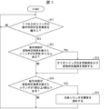
- 9 is a flowchart showing an example of processing executed by the abnormality detection device according to one aspect of the present disclosure.
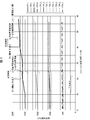
- FIG. 7 is a graph showing a specific example in which the normal range is changed in accordance with the tendency of fluctuations in operating time in the abnormality detection device according to one aspect of the present disclosure.
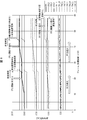
- 8 is a graph showing another specific example in which the normal range is changed according to the fluctuation tendency of the operation time in the abnormality detection device according to the one aspect of the present disclosure.
- 9 is a flowchart showing an example of processing executed by the abnormality detection device according to one aspect of the present disclosure.
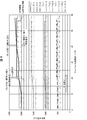
- 7 is a graph showing a specific example in which the normal range is changed in accordance with the tendency of fluctuations in operating time in the abnormality detection device according to one aspect of the present disclosure.
- FIG. 10 is a schematic diagram showing another example of determining the width of the normal range in the abnormality detection device according to the one aspect of the present disclosure.
- FIG. 8 is a schematic diagram showing a range in which a variation tendency of operating time is evaluated when a plurality of manifolds are used in the abnormality detection system according to one aspect of the present disclosure.
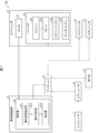
- FIG. 1 is a block diagram showing an outline of a main configuration of an abnormality detection system 100 according to one aspect of the present disclosure.
- the abnormality detection system 100 includes a compressor 1, a regulator 2, a discharge port 3, a manifold 4, an air cylinder 5, an abnormality detection device 6, and a display device 7.
- the solid line shows the flow of data
- the dotted line shows the flow of gas.
- the abnormality detection system 100 is a system in which the abnormality detection device 6 detects an abnormality in at least one of the air cylinders 5 on the basis of the fluctuation tendency of a plurality of operation times of the plurality of air cylinders 5 driven by the inflow and outflow of gas. is there.
- the abnormality detection device 6 sets a range of operation time in which each air cylinder 5 is determined to be normal as a normal range, and changes the range based on the fluctuation tendency of a plurality of operation times.
- Gas having the same pressure, which is pressurized by the compressor 1 and adjusted by the regulator 2 is supplied to the plurality of air cylinders 5 as the solenoid valves provided in the manifold 4 are opened and closed.
- the abnormality detection device 6 also functions as a control device that controls the drive of one or more air cylinders 5.
- the compressor 1 can pressurize gas and supply it to the regulator 2.
- the regulator 2 is an adjuster capable of adjusting the pressure of the gas supplied from the compressor 1 to a desired value and then supplying the gas to the manifold 4.
- the exhaust port 3 can receive gas that has become unnecessary for adjusting the pressure inside the air cylinder 5 via the manifold 4 and can discharge the gas to the outside.
- the manifold 4 is a flow path provided with one or more solenoid valves that can be opened and closed under the control of the abnormality detection device 6.
- the manifold 4 receives an opening / closing instruction of the solenoid valve from the control unit 61 of the abnormality detection device 6, the manifold 4 opens / closes the corresponding solenoid valve and releases gas between the opened / closed solenoid valve and the cylinder 53 of the air cylinder 5. Can flow in and out.
- One or more air cylinders 5 may be connected to the manifold 4, and a specific solenoid valve communicating with the specific air cylinder 5 may be opened or closed according to an instruction from the abnormality detection device 6.
- the air cylinder 5 includes a sensor 51 and a cylinder 53, and the cylinder 53 includes a piston 531, a rod 533, a piston packing 535, and a rod packing 537.
- the air cylinder 5 can slide the piston 531 arranged inside the cylinder 53 by allowing gas to flow in and out of the manifold 4.
- the air cylinder 5 may connect various mechanisms (not shown) to the other end of the rod 533, one end of which is connected to the piston 531, and the mechanism may be operated according to the sliding of the piston 531.
- the sensor 51 can notify the abnormality detection device 6 when it detects that the piston 531 is located at the pull-back end position or the push-out end position, which will be described later, inside the cylinder 53.
- the sensor 51 may be, for example, a limit switch that indicates the position of the piston 531 by turning the switch ON / OFF.
- the cylinder 53 is formed so as to have a cylindrical inner wall surface inside the air cylinder 5, and ports for allowing gas to flow in and out are provided near both ends.
- the cylinder 53 can adjust the internal gas pressure by allowing gas to flow in and out from the port as the solenoid valve in the manifold 4 is opened and closed.
- One end of the cylinder 53 is closed, and the other end is provided with a hole corresponding to the size of the rod 533 so that the rod 533 can penetrate the cylinder 53.
- the piston 531 is a plug-like member that is slidably arranged inside the cylinder 53, and a rod 533 is connected to one end of the piston 531. Inside the cylinder 53, the piston 531 slides inside the cylinder 53 in accordance with the difference in gas pressure in the inner region of the cylinder 53 that faces the piston 531.
- the rod 533 is a rod-shaped member whose one end is connected to one end of the piston 531 and can move according to sliding of the piston 531.
- the rod 533 is arranged so as to pass through a hole provided at one end of the cylinder 53, and the amount of protrusion from the end of the cylinder 53 changes in accordance with the sliding of the piston 531.
- the piston packing 535 is a packing fixed to the piston 531 in order to prevent gas from moving between the inner regions of the cylinder 53 that face each other with the piston 531 interposed therebetween.
- the piston packing 535 may be an O-ring formed of rubber or resin, for example.
- the rod packing 537 is fixed to one end of the cylinder 53 in order to prevent the gas from moving to the outside through the gap between the rod 533 and the hole corresponding to the size of the rod 533 provided in the one end of the cylinder 53. It is the packed. Similar to the piston packing 535, the rod packing 537 may be an O-ring formed of, for example, rubber or resin.
- the abnormality detection device 6 is a device that detects an abnormality of the air cylinder 5 having the piston 531 and includes a control unit 61.
- the control unit 61 includes an operation time acquisition unit 611, an abnormality determination unit 613, and a setting unit 615.
- the control unit 61 centrally controls each unit of the abnormality detection device 6.
- the control unit 61 can transmit an opening / closing instruction of the solenoid valve to the manifold 4 to open / close a specific solenoid valve of the manifold 4.
- the control unit 61 can receive a notification from the sensor 51 that the piston 531 is located at a pullback end position or an extrusion end position, which will be described later.
- the operation time acquisition unit 611 can acquire a plurality of operation times required for each operation of the plurality of air cylinders 5 based on the plurality of notifications received by the control unit 61 from each of the plurality of sensors 51.
- the operating time includes the pushing time required for pushing out the piston 531 in the cylinder 53 of the air cylinder 5 and the pullback time required for pullback. More specifically, the operation time acquisition unit 611 acquires, as the extrusion time, the time required for the piston 531 at the pullback end position described below to move to the extrusion end position described below. Further, the time required for the piston 531 at the push-out end position to move to the pull-back end position is acquired as the pull-back time.
- the operation time acquisition unit 611 transmits the plurality of operation times acquired for the plurality of air cylinders 5 to the abnormality determination unit 613.
- the operation time is the total of the extrusion time and the pullback time, but the operation time is not limited to this, and the operation time may be either the extrusion time or the pullback time.
- the abnormality determination unit 613 determines whether or not the fluctuation tendencies of the plurality of operation times regarding the plurality of air cylinders 5 received from the operation time acquisition unit 611 are wholly in agreement. When it is determined that the plurality of fluctuation trends of the operation time are entirely the same, the abnormality determination unit 613 can instruct the setting unit 615 to change the normal range in the plurality of air cylinders 5. For example, with respect to the air cylinders 5 having a predetermined ratio or more out of the plurality of air cylinders 5, the abnormality determination unit 613 determines that the operating time of each air cylinder 5 deviates from the normal range corresponding to the air cylinder. For example, it may be determined that the fluctuation tendencies of the plurality of operation times are entirely the same.
- the predetermined ratio and the predetermined number may be any values.
- the predetermined ratio may be 90% (rounding up after the decimal point), or the predetermined number may be N-1.
- the predetermined number is set to Nm.
- the predetermined number is preferably less than N and greater than N / 2.
- the abnormality determination unit 613 determines that the fluctuation tendencies of the plurality of operation times do not entirely match, it determines that the operation time of the air cylinder 5 is abnormal for the air cylinder 5 that deviates from the corresponding normal range. You may.
- the abnormality determination unit 613 may notify the outside that an abnormality has occurred in the air cylinder 5 determined to be abnormal.
- the setting unit 615 can change a plurality of normal ranges regarding a plurality of operating times of the plurality of air cylinders 5 according to an instruction from the abnormality determining unit 613.
- the setting unit 615 can change the normal range for the operation time, which is individually set for all the air cylinders 5 connected to the manifold 4.
- the setting unit 615 does not change the width of the normal range, and can shift only the range in accordance with the fluctuation tendency of a plurality of operation times.
- the width of the normal range indicates the difference between the upper limit value and the lower limit value of the normal range.
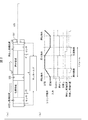
- FIG. 2A and 2B are schematic diagrams showing the outline of the air cylinder 5 according to one aspect of the present invention.
- FIG. 2A shows the outline of the air cylinder 5
- FIG. 2B shows the extrusion time in the air cylinder 5. It also shows the definition of withdrawal time.
- FIG. 2 (a) An outline of the air cylinder 5 is shown in Fig. 2 (a).
- the air cylinder 5 is formed with a cylindrical cylinder 53, and both ends of the cylinder 53 can allow gas to flow into and out of the manifold 4 through ports (not shown).
- a piston 531 including a piston packing 535 is slidably provided inside the air cylinder 5, and an end of a rod 533 is connected to one end of the piston 531.
- One end of the rod 533 penetrates a hole provided at the end of the cylinder 53, and a rod packing 537 is fixed around the hole.
- one end of the cylinder 53 is closed by a sealing member other than the cylinder 53, and the rod 533 penetrates a hole provided in the sealing member. However, if one end of the cylinder 53 is closed and the rod 533 penetrates the hole, the sealing member may not be used.
- two sensors 51 are provided near the end of the cylinder 53.
- a region where the rod 533 does not exist is a pull-back region
- a region where the rod 533 exists is an extrusion region.
- the step of moving the piston 531 so as to compress the pullback area when the pressure of the pullback area becomes less than the pressure of the pushout area is referred to as a pullback step
- the process of moving the piston 531 so as to compress the extrusion region is referred to as an extrusion process. That is, the rod 533 is pulled back inside the cylinder 53 in the pulling back process, and the rod 533 is pushed out of the cylinder 53 in the pushing out process.
- the position of the piston 531 when the piston 531 compresses the pullback region to the limit in the pullback process is the pullback end position, and the position of the piston 531 when the piston 531 compresses the pushout region to the limit in the extrusion process. Is the extrusion end position.
- the sensor 51 notifies the outside to that effect.
- the definition of the extrusion time and the withdrawal time in the air cylinder 5 is shown using (b) of FIG.
- the “outward end” and the “return end” of the “cylinder operation” indicate the end of the extrusion process and the withdrawal process, respectively.
- “Enable”, “push”, and “pullback” of “input” are “whether or not available” and “driven by push of rod 533” for various mechanisms connected to the end of rod 533. "Whether or not there is” and “Whether or not driving is performed by pulling back the rod 533” are shown.
- the “push-out end position” and the “pullback end position” respectively indicate whether or not the piston 531 is located at the push-out end position and whether or not it is located at the pullback end position.
- the abnormality detection device 6 controls the manifold 4 from the state where the piston 531 is at the pull-back end position to start the extrusion process to move the piston 531 to the extrusion end position, and then the manifold 4 is moved. Is controlled to start the pullback process, and the operation time required to move the piston 531 to the pullback end position is one frame. Further, in one frame, the time required for the piston 531 at the pull-back end position to move to the push-out end position is defined as the push-out time, and the time required for the piston 531 at the push-out end position to move to the pull-back end position. Is the withdrawal time.
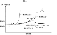
- FIG. 3 is a schematic diagram showing an outline of changing the normal range in accordance with the variation tendency of the operation time in the abnormality detection device 6 according to one aspect of the present disclosure.
- the horizontal axis represents the number of operations of reciprocating movement of the piston 531 in the cylinder 53 in order to execute the extrusion process and the withdrawing process
- the vertical axis represents the movement required for the reciprocating movement of the piston 531 once.
- the graph of "normal product” shows the air cylinder 5 which is operating normally
- the graphs of "abnormality product 1" and "abnormality product 2" show the air cylinder 5 which has an abnormality. There is.
- Threshold value (H) and “threshold value (L)” indicate the upper limit value and the lower limit value of the normal range, respectively. That is, the difference value between the “threshold value (H)” and the “threshold value (L)” corresponds to the width of the normal range.
- the same normal range is set for “normal product”, “abnormality-generated product 1", and “abnormality-generated product 2”, but a normal range is set for each air cylinder 5.
- the “temperature / pressure fluctuation” indicates fluctuations in the temperature and pressure of the internal gas in the air cylinder 5.
- the graph of “normal product” is substantially flat, but the graphs of “abnormality product 1” and “abnormality product 2” show “threshold value (L)” as the number of operations increases. Exceeded and deviated from the normal range.
- the abnormality determination unit 613 of the abnormality detection device 6 the fluctuation tendency of the movement time in the three graphs of “normal product”, “abnormal product 1”, and “abnormal product 2” is generally over the normal range. It is determined that the deviation is in the direction of Then, the setting unit 615 changes the normal range, that is, each of the “threshold value (H)” and the “threshold value (L)”.
- the setting unit 615 moves only the position of the normal range in the vertical axis direction while maintaining the width of the normal range.
- the setting unit 615 may set the normal range in any way as long as each graph is within the normal range after the change. For example, the setting unit 615 sets the value of each graph after the change to the center of the normal range.
- the values of the "threshold (H)" and the “threshold (L)" after the change may be set so that they are located in the vicinity.
- the setting unit 615 sets the values of the “threshold (H)” and the “threshold (L)” after the change so that the upper limit value or the lower limit value of the normal range before the change is located in the center of the normal range after the change. May be set.
- the “threshold value (H)” and the “threshold value (L)” are temporarily changed to a side having a large travel time value, and then changed back to the original values. This is because, as a result of judging the fluctuation tendency of the moving time in the three graphs by using the temporarily changed “threshold (H)” and “threshold (L)”, the fluctuation tendency is generally lower than the normal range. It depends on the result of judgment that there is a tendency.
- the abnormality detection device 6 can change the normal range when the fluctuation tendencies of the plurality of operation times of the plurality of air cylinders 5 are entirely the same. That is, the abnormality detection device 6 can change the normal range according to the temperature and pressure fluctuations of the internal gas in the air cylinder 5.
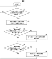
- FIG. 4 is a flowchart showing an example of processing executed by the abnormality detection device 6 according to one aspect of the present disclosure.
- the operation time acquisition unit 611 of the abnormality detection device 6 determines a plurality of operation times corresponding to each of the plurality of air cylinders 5 based on the notification received from each of the plurality of sensors 51 of the plurality of air cylinders 5. get. After that, the abnormality determination unit 613 determines whether or not there is at least one air cylinder 5 whose operating time exceeds the normal range for the plurality of operating times acquired by the operating time acquiring unit 611 (S1). When it is determined that the air cylinders 5 exist (YES in S1), the control unit 61 operates the plurality of air cylinders 5 a predetermined number of times or a predetermined time (S2: operation time acquisition step). After that, the process proceeds to S3. On the other hand, if it is determined that there is not any (NO in S1), S1 is executed again. The acquisition and determination (S1) of the operation time are performed every predetermined period (for example, 1 minute to 1 hour).
- the abnormality determination unit 613 determines whether or not there are a predetermined number (Nm) or more of air cylinders 5 whose operating time exceeds the normal range (S3: abnormality determination step). When it is determined that the number is equal to or more than the predetermined number (YES in S3), the abnormality determination unit 613 instructs the setting unit 615 to update the normal range, and the setting unit 615 updates the normal ranges of all the air cylinders 5 according to the instruction. (S4: setting step). After that, the process proceeds to S5. On the other hand, if it is determined that the number is not more than the predetermined number (NO in S3), the process directly proceeds to S5.
- the abnormality determination unit 613 determines whether or not the number of air cylinders 5 whose operation time exceeds the normal range is 1 or more and m or less (S5: abnormality determination step). When it is determined that the number is 1 or more and m or less (YES in S5), the abnormality determining unit 613 determines that the air cylinder 5 whose operating time exceeds the normal range is abnormal and notifies the abnormality of the air cylinder 5. (S6: abnormality determination step). After that, the process proceeds to S1 and the processes of S1 to S6 are executed again. On the other hand, if it is determined that the number of air cylinders 5 whose operating time exceeds the normal range is greater than 0 or m (NO in S5), the process directly proceeds to S1 and the processes of S1 to S6 are executed again.
- the abnormality detection device 6 changes the normal range for the plurality of operating time fluctuation tendencies of the plurality of air cylinders 5 when they are wholly in agreement, and changes the normal range when they are not entirely in agreement. It is possible to detect the abnormality of the air cylinder 5 that deviates from the above. Thereby, it is possible to realize the abnormality detecting device 6 which is excellent in convenience and can detect the abnormality of the air cylinder 5 in consideration of the change of the ambient temperature without using an additional member such as a temperature sensor. it can.
- FIG. 5 is a graph showing a specific example of changing the normal range in accordance with the tendency of fluctuations in operating time in the abnormality detection device 6 according to one aspect of the present disclosure.
- FIG. 6 is a graph showing another specific example in which the normal range is changed according to the variation tendency of the operation time in the abnormality detection device 6 according to the one aspect of the present disclosure.
- the horizontal axis represents the frame described using FIG. 2B, and the vertical axis represents the operating time of one frame.
- “CYL1”, “CYL2”, “CYL3”, and “CYL4” indicate the operating time of each air cylinder 5.
- “Th1_H” and “Th1_L”, “Th2_H” and “Th2_L”, “Th3_H” and “Th3_L”, and “Th4_H” and “Th4_L” are the upper and lower limits of the normal range set for the corresponding air cylinder 5. The respective values are shown.
- the upper limit value and the lower limit value of the normal range for example, a value of ⁇ 5% with respect to the average operating time of each air cylinder 5 may be set, or a value obtained by adding or subtracting the standard deviation may be set. ..
- the abnormality determination unit 613 determines that the four air cylinders 5 have four values. It is determined that the fluctuation trends of the operating time are entirely the same. Then, the setting unit 615 changes all the normal ranges for the four air cylinders 5.
- the setting unit 615 changes all the normal ranges for the four air cylinders 5.
- the abnormality determination unit 613 determines whether or not the value of the horizontal axis is between “53” and “58” below the lower limit value of the normal range also in the other air cylinders 5. Since the values on the horizontal axis are between “53” and “58”, “CYL1", “CYL2”, and “CYL4" are always within the normal range, so the abnormality determination unit 613 relates to the four air cylinders 5. It is determined that the fluctuation trends of the four operation times do not entirely match. Then, the abnormality determination unit 613 determines that “CYL3” is abnormal and notifies it.
- the abnormality detection device 6 can determine the fluctuation tendency of a plurality of operation times regarding the plurality of air cylinders 5 using the normal range. Then, the normal range can be changed or the abnormality of the air cylinder 5 can be notified according to the determination result.
- the abnormality detection device 6 can change the normal range or notify the abnormality of the air cylinder 5 based on the overall variation tendency of the plurality of operation times of the plurality of air cylinders 5.
- the abnormality determination unit 613 determines that a predetermined number or more of the air cylinders 5 among the plurality of air cylinders 5 have deviated from the upper limit value or the lower limit value of the normal range (on the same side). Alternatively, it may be determined that the fluctuation tendencies of the plurality of operation times are entirely the same. Note that both “when the upper limit is exceeded” and “when the lower limit is exceeded” may be expressed as “when the threshold is exceeded” or “when the normal range is exceeded”.
- the configuration of the abnormality detection system 100 will be described with reference to FIG. 1.
- the basic configuration of the abnormality detection system 100 is the same as the above configuration example, but a part of the configuration is different.
- the abnormality detection device 6 further sets a variation determination range inside the normal range, and the abnormality determination unit 613 combines the normal range and the variation determination range to detect a plurality of operation times of a plurality of air cylinders 5. It is determined whether or not the fluctuation trends are wholly consistent.
- the abnormality determination unit 613 determines that the operation time of at least one air cylinder 5 deviates from the normal range corresponding to the air cylinder 5, and a predetermined ratio or more of the plurality of air cylinders 5 or For a predetermined number or more of air cylinders 5, if the operating time of each air cylinder 5 deviates from the corresponding variation determination range, it is possible to determine that the variation tendencies of a plurality of operating times are generally the same. it can. Then, when the abnormality determining unit 613 determines that the fluctuation tendencies of the plurality of operation times are wholly in agreement, the setting unit 615, together with the plurality of normal ranges regarding the plurality of operation times of the plurality of air cylinders 5, together. It is possible to change a plurality of fluctuation determination ranges.
- FIG. 7 is a flowchart showing an example of processing executed by the abnormality detection device 6 according to one aspect of the present disclosure.
- the abnormality determination unit 613 of the abnormality detection device 6 determines that the air cylinder 5 whose operation time exceeds the normal range is 1 for the plurality of operation times acquired by the operation time acquisition unit 611. It is determined whether or not there are one or more (S11: abnormality determination step). When it is determined that the air cylinders 5 are present (YES in S11), the abnormality determination unit 613 determines whether or not there is a predetermined number (Nm) or more of air cylinders 5 whose operation time exceeds the variation determination range (S12: abnormality determination step). ). On the other hand, if it is determined that there is not any (NO in S11), the process of S11 is executed again.
- the abnormality determination unit 613 updates the setting unit 615 to the normal range. Then, the setting unit 615 updates the normal range and the variation determination range of all the air cylinders 5 according to the instruction (S13: setting step). After that, the process proceeds to S14. On the other hand, if it is determined that the number is not more than the predetermined number (NO in S12), the process directly proceeds to S14.
- the abnormality determination unit 613 determines whether or not the number of air cylinders 5 whose operation time exceeds the variation determination range is 1 or more and m or less (S14: abnormality determination step). When it is determined that the number is 1 or more and m or less (YES in S14), the abnormality determination unit 613 determines that the air cylinder 5 whose operating time exceeds the normal range is abnormal and notifies the abnormality of the air cylinder 5. Yes (S15: abnormality determination step). After that, the process proceeds to S11, and the processes of S11 to S15 are executed again.
- the abnormality detection device 6 can determine the presence or absence of abnormality of the air cylinder 5 by combining the normal range and the variation determination range with respect to the plurality of operating time variation tendencies of the plurality of air cylinders 5.
- FIG. 8 is a graph showing a specific example in which the normal range is changed in accordance with the variation tendency of the operation time in the abnormality detection device 6 according to the one aspect of the present disclosure.
- the definition of each item is the same as in FIGS. 5 and 6.
- “CYL1” exceeds “Th1_H” near the value on the horizontal axis of “19”.
- the abnormality determination unit 613 of the abnormality detection device 6 detects that “CYL1” exceeds “Th1_H”, it exceeds the upper limit value of the variation determination range in the other air cylinders 5 within a predetermined time from the time of detection. Or not. In the illustrated example, it is determined whether or not the value on the horizontal axis is in the vicinity of "19" and exceeds the upper limit of the variation determination range.
- the abnormality determination unit 613 determines that the four operation time periods of the four air cylinders 5 are equal to each other. It is determined that the fluctuation trends are entirely the same. Then, the setting unit 615 changes all the normal range and the variation determination range for each of the four air cylinders 5.
- the abnormality detection device 6 uses the normal range and the fluctuation determination range to determine the fluctuation tendency of a plurality of operation times for the plurality of air cylinders 5, and updates the normal range and the fluctuation determination range and notifies the abnormality. be able to.
- the setting unit 615 updates the normal range so as to move the position of the normal range in the vertical axis direction while maintaining the width of the normal range.
- the setting unit 615 may change the width of the updated normal range when updating the normal range.
- the setting unit 615 determines that the normal range of each air cylinder 5 is the upper limit value of the normal range when the abnormality determining unit 613 determines that the plurality of movement time fluctuation tendencies are entirely the same.
- the difference from the lower limit may be changed to be larger than that before the change, or may be changed to be smaller than that before the change.
- the setting unit 615 may change the normal range of each air cylinder such that one of the upper limit value and the lower limit value of the normal range before the change falls within the normal range after the change.
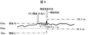
- FIG. 9 is a schematic diagram showing another example of determining the width of the normal range in the abnormality detection device 6 according to one aspect of the present disclosure.
- “threshold value (H)” and “threshold value (L)” indicate the upper limit value and the lower limit value of the normal range, respectively.
- “Over CYL1 threshold (H)” indicates that the operating time of one air cylinder 5 exceeds the upper limit of the normal range.
- the abnormality determination unit 613 of the abnormality detection device 6 determines that the operation time of one air cylinder 5 exceeds the upper limit value of the normal range, it operates all the air cylinders 5 a predetermined number of times (500 frames in FIG. 9). After that, it is determined whether or not there are a predetermined number or more of air cylinders 5 whose operating time exceeds the normal range.
- the abnormality determination unit 613 determines that there are a predetermined number or more of air cylinders 5 whose operating time exceeds the normal range, the normal range is updated without changing the width of the normal range in the configuration example and the operation example. It was on the other hand, in the present modification, the setting unit 615 sets the average value of the operating time of the air cylinder 5 obtained by the predetermined number of operations to the center of the updated normal range, and increases or decreases by a predetermined ratio with respect to the average value. Set the value to the upper and lower limits of the normal range after updating.
- the width of the normal range also increases or decreases according to the increase or decrease of the average value of the operating time. For example, if the average value of the operating time increases, the width of the normal range expands. On the other hand, when the average value decreases, the width of the normal range narrows. By varying the width of the normal range according to the variation of the operating time, it becomes easier to detect the abnormality of the air cylinder 5.
- the plurality of air cylinders 5 are connected to one manifold 4.
- the abnormality detection device 6 may control the opening / closing of the solenoid valve for the plurality of manifolds 4, and the plurality of air cylinders 5 may be connected to each manifold 4.
- FIG. 10 is a schematic diagram showing a range in which the variation tendency of the operation time is evaluated when a plurality of manifolds are used in the abnormality detection system 100 according to one aspect of the present disclosure.
- one compressor 1 supplies gas at a pressure P0 to two regulators 2A and 2B.
- the regulator 2A supplies gas to the manifold 4A at pressure P1
- the regulator 2B supplies gas to the manifold 4B at pressure P2.
- the operating time of the plurality of air cylinders 5 changes more uniformly (more uniformly) depending on the temperature change if the pressure of the gas supplied to each of the plurality of air cylinders 5 is the same. Therefore, the abnormality detection device 6 determines the presence / absence of abnormality of a plurality of air cylinders 5 that are supplied with gas of the same pressure from one regulator 2A, for example, included in the broken line frame of FIG. ..
- the setting unit 615 is configured to update the normal range based on a plurality of movement time fluctuation trends, but for example, the range in which the normal range can be set may be limited.
- the value of the operating time which is acquired only when the pressure of the gas supplied to the air cylinder 5 abnormally increases or decreases due to an abnormality in the compressor 1 or the regulator 2, does not include the normal range in the settable range. May be limited to.
- the abnormality determination unit 613 notifies that a member other than the air cylinder 5 such as the compressor 1 or the regulator 2 has an abnormality. Good.
- the control block of the abnormality detection device 6 may be realized by a logic circuit (hardware) formed in an integrated circuit (IC chip) or the like, or may be realized by software.
- the abnormality detection device 6 includes a computer that executes the instructions of a program that is software that realizes each function.
- the computer includes, for example, one or more processors and a computer-readable recording medium that stores the program. Then, in the computer, the processor reads the program from the recording medium and executes the program to achieve the object of the present invention.
- a CPU Central Processing Unit
- the recording medium a "non-transitory tangible medium” such as a ROM (Read Only Memory), a tape, a disk, a card, a semiconductor memory, a programmable logic circuit, or the like can be used. Further, a RAM (Random Access Memory) for expanding the above program may be further provided.
- the program may be supplied to the computer via any transmission medium (communication network, broadcast wave, etc.) capable of transmitting the program.
- any transmission medium communication network, broadcast wave, etc.
- one aspect of the present invention can also be realized in the form of a data signal embedded in a carrier wave, in which the program is embodied by electronic transmission.
- An abnormality detection device is an abnormality detection device that detects an abnormality in a system including a plurality of air cylinders, and an operation time period that acquires a plurality of operation times required for each operation of a plurality of air cylinders.
- a setting unit that changes a plurality of normal ranges regarding a plurality of operating times of the plurality of air cylinders, the abnormality determining unit is configured to change the plurality of operating times as a whole.
- the abnormality detection device can change a plurality of normal ranges or detect an abnormality of the air cylinder based on the fluctuation tendency of a plurality of operation times required for each operation of the plurality of air cylinders. .. Therefore, it is possible to realize a highly convenient abnormality detection device that can detect an abnormality in the air cylinder in consideration of changes in ambient temperature.
- the abnormality determination unit is configured such that, with respect to at least a predetermined ratio or a predetermined number of air cylinders of the plurality of air cylinders, the operation time of each air cylinder corresponds to the air cylinder. If it deviates from the normal range, it may be determined that the fluctuation tendencies of the plurality of operation times are entirely the same. According to this configuration, the normal range can be changed if the operating time of the air cylinders of the predetermined ratio or more or the predetermined number or more deviates from the normal range.
- a variation determination range is set inside the corresponding normal range with respect to the operation time of each air cylinder, and the abnormality determination unit includes the operation of at least one air cylinder. Time deviates from the normal range corresponding to the air cylinder, and for a plurality of air cylinders having a predetermined ratio or more or a predetermined number or more, the operating time of each air cylinder corresponds to If it deviates from the variation determination range, it may be determined that the variation tendencies of the plurality of operation times are generally the same. According to this configuration, by using the variation determination range inside the normal range, the normal range can be changed at an early stage according to the temperature change.
- the setting unit when it is determined that the fluctuation tendencies of the plurality of operation times are wholly in agreement, the plurality of operation times of the plurality of operation times of the plurality of air cylinders.
- a plurality of variation determination ranges may be changed together with the normal range.
- the abnormality detection device can detect a change in a plurality of normal ranges or an abnormality in the air cylinder by using the variation determination range changed together with the normal range.
- the setting unit when it is determined that the change tendency of the plurality of operation times are generally the same, the normal range of each air cylinder, the normal range of the The difference between the upper limit value and the lower limit value may be changed to be larger than that before the change.
- an appropriate normal range can be set according to the temperature. For example, when the temperature is high, the variation in the operating time becomes large, so that erroneous detection can be suppressed.
- the setting unit when it is determined that the change tendency of the plurality of operation times are generally the same, the normal range of each air cylinder, the normal range of the The difference between the upper limit value and the lower limit value may be changed to be smaller than that before the change.
- an appropriate normal range can be set according to the temperature. For example, when the temperature is low, variations in operating time are reduced, so that the accuracy of detection can be improved.
- the setting unit when it is determined that the fluctuation tendency of the plurality of operation times are wholly in agreement, sets the normal range of each air cylinder to the normal state before the change.
- One of the upper limit value and the lower limit value of the range may be changed so as to be within the normal range after the change. According to this configuration, the normal range can be appropriately changed so that the normal operation time changed according to the temperature change falls within the changed normal range.
- the predetermined number when the number of the plurality of air cylinders is N, the predetermined number may be (N-1). According to this configuration, it is possible to appropriately determine the abnormality of one air cylinder unless the two air cylinders are broken at the same time.
- gas having the same pressure may be supplied to the plurality of air cylinders. According to this configuration, it is possible to appropriately determine the abnormality of the air cylinder according to the fluctuation tendency of the plurality of operation times.
- An abnormality detection system according to one aspect of the present disclosure, an abnormality detection device according to the one aspect, a plurality of air cylinders, a plurality of solenoid valves for controlling the gas supplied to the plurality of air cylinders, A control device that controls opening and closing of the plurality of electromagnetic valves.
- An anomaly detection method is an anomaly detection method for detecting an anomaly in a system including a plurality of air cylinders, and an operation time for acquiring a plurality of operation times required for each operation of a plurality of air cylinders.
Landscapes
- Physics & Mathematics (AREA)
- Engineering & Computer Science (AREA)
- General Physics & Mathematics (AREA)
- Chemical & Material Sciences (AREA)
- Analytical Chemistry (AREA)
- Automation & Control Theory (AREA)
- Combustion & Propulsion (AREA)
- Fluid Mechanics (AREA)
- Mechanical Engineering (AREA)
- General Engineering & Computer Science (AREA)
- Testing Of Devices, Machine Parts, Or Other Structures Thereof (AREA)
- Fluid-Pressure Circuits (AREA)
- Combined Controls Of Internal Combustion Engines (AREA)
- Testing And Monitoring For Control Systems (AREA)
Abstract
利便性に優れた異常検知装置等を実現する。異常検知装置(6)は、複数のエアシリンダ(5)の複数の動作時間を取得する動作時間取得部(611)と、前記複数の動作時間の変動傾向が、全体的に一致しているか否かを判定する異常判定部(613)と、前記複数の動作時間の変動傾向が全体的に一致していると判定された場合、前記複数のエアシリンダの複数の動作時間に関する複数の正常範囲を変更する設定部(615)と、を備え、前記異常判定部は、前記複数の動作時間の変動傾向が全体的に一致していないと判定した場合、エアシリンダの動作時間が、対応する前記正常範囲から逸脱した前記エアシリンダを異常であると判定する。
Description
本発明はエアシリンダにおける異常を検知する異常検知装置等に関する。
駆動することによって各種動作を実行するエアシリンダに対して、異常の有無を検知する異常検知装置が従来技術として知られている。例えば、特許文献1にはアクチュエータの可動部の移動時間に基づいて該アクチュエータの異常を検出する異常検出システムが開示されている。
しかしながら、上述のような従来技術は故障以外の要因によって装置の駆動源がオンオフ切換されてから該装置の稼動状態に応じた検出信号が変化するまでの時間が変動することが考慮されていない。具体的には、周囲温度が変化した場合であっても標準データを再設定することができず、時間差の変動量が温度変化によるものであるか装置の異常によるものであるかを区別することができない。
本開示の一態様は前記の問題に鑑みてなされたものであり、周囲温度の変化を考慮してエアシリンダの異常を検知することができる、利便性に優れた異常検知装置等を実現することができる。
本開示は、前述した課題を解決するために、以下の構成を採用する。
すなわち、本開示の一側面に係る異常検知装置は、複数のエアシリンダを備えるシステムの異常を検知する異常検知装置であって、複数のエアシリンダのそれぞれの動作に要する複数の動作時間を取得する動作時間取得部と、複数のエアシリンダに関する前記複数の動作時間の変動傾向が、全体的に一致しているか否かを判定する異常判定部と、前記複数の動作時間の変動傾向が全体的に一致していると判定された場合、前記複数のエアシリンダの複数の動作時間に関する複数の正常範囲を変更する設定部と、を備え、前記異常判定部は、前記複数の動作時間の変動傾向が全体的に一致していないと判定した場合、エアシリンダの動作時間が、対応する前記正常範囲から逸脱した前記エアシリンダを異常であると判定する。
本開示の一側面に係る異常検知方法は、複数のエアシリンダを備えるシステムの異常を検知する異常検知方法であって、複数のエアシリンダのそれぞれの動作に要する複数の動作時間を取得する動作時間取得ステップと、複数のエアシリンダに関する前記複数の動作時間の変動傾向が、全体的に一致しているか否かを判定する異常判定ステップと、前記異常判定ステップにて前記複数の動作時間の変動傾向が全体的に一致していると判定された場合、前記複数のエアシリンダの複数の動作時間に関する複数の正常範囲を変更する設定ステップと、を含み、前記異常判定ステップでは、前記複数の動作時間の変動傾向が全体的に一致していないと判定した場合、エアシリンダの動作時間が、対応する前記正常範囲から逸脱した前記エアシリンダを異常であると判定する。
本発明の一態様によれば、周囲温度の変化を考慮してエアシリンダの異常を検知することができる、利便性に優れた異常検知装置を実現することができる。
§1 構成例
(異常検知システムの構成)
図1は、本開示の一側面の異常検知システム100の要部構成の概要を示すブロック図である。異常検知システム100は、コンプレッサ1、レギュレータ2、排出口3、マニホールド4、エアシリンダ5、異常検知装置6、および表示装置7を備えている。なお、図1において実線はデータの流れを示し、点線は気体の流れを示している。
(異常検知システムの構成)
図1は、本開示の一側面の異常検知システム100の要部構成の概要を示すブロック図である。異常検知システム100は、コンプレッサ1、レギュレータ2、排出口3、マニホールド4、エアシリンダ5、異常検知装置6、および表示装置7を備えている。なお、図1において実線はデータの流れを示し、点線は気体の流れを示している。
異常検知システム100は、気体の流入出によって駆動する複数のエアシリンダ5に関する複数の動作時間の変動傾向に基づいて、少なくともいずれかのエアシリンダ5の異常を異常検知装置6にて検知するシステムである。異常検知装置6は、各エアシリンダ5が正常であると判定する動作時間の範囲を正常範囲として設定し、複数の動作時間の変動傾向に基づいて変更する。複数のエアシリンダ5には、コンプレッサ1によって加圧され、レギュレータ2によって調整された同じ圧力の気体が、マニホールド4に設けられた電磁弁の開閉に伴って供給される。また、エアシリンダ5からは電磁弁の開閉に伴って、不要となった気体が排出口3より排出される。マニホールド4における電磁弁の開閉は異常検知装置6によって制御されるため、異常検知装置6は1つ以上のエアシリンダ5における駆動を制御する制御装置としても機能する。
コンプレッサ1は、気体を加圧してレギュレータ2に供給することができる。レギュレータ2は、コンプレッサ1から供給された気体の圧力を所望の値に調整した後、マニホールド4に供給することができる調整器である。排出口3は、エアシリンダ5の内部の圧力を調整するために不要となった気体をマニホールド4を介して受け付け、外部に排出することができる。
マニホールド4は、異常検知装置6の制御にしたがって開閉することが可能な1つ以上の電磁弁を備えた流路である。マニホールド4は、異常検知装置6の制御部61から電磁弁の開閉指示を受け付けると、対応する電磁弁を開閉させ、開閉させた電磁弁と連通するエアシリンダ5のシリンダ53との間で気体を流入出させることができる。マニホールド4には1つ以上のエアシリンダ5が接続されてもよく、異常検知装置6からの指示にしたがって、特定のエアシリンダ5と連通する特定の電磁弁を開閉してもよい。
エアシリンダ5は、センサ51およびシリンダ53を備えており、シリンダ53は、ピストン531、ロッド533、ピストンパッキン535、およびロッドパッキン537を備えている。エアシリンダ5は、マニホールド4との間で気体を流入出させることでシリンダ53の内部に配されたピストン531を摺動させることができる。エアシリンダ5は、ピストン531に一端が接続されたロッド533の他端に図示しない各種機構を接続してもよく、ピストン531の摺動に応じて該機構を動作させてもよい。
センサ51は、シリンダ53の内部においてピストン531が後述する引戻し終端位置または押出し終端位置に位置することを検知すると、異常検知装置6に通知することができる。センサ51は、例えばピストン531の位置をスイッチのON/OFFで示すリミットスイッチであってもよい。
シリンダ53は、エアシリンダ5の内部に円筒状に形成された内壁面を有するように形成されており、両端の近傍には気体が流入出するためのポートが設けられている。シリンダ53は、マニホールド4における電磁弁の開閉に伴ってポートから気体を流入出させることにより、内部の気体圧力を調整することができる。シリンダ53の一端は閉塞されており、他端はロッド533がシリンダ53を貫通できるようにロッド533の大きさに応じた穴が設けられている。
ピストン531は、シリンダ53の内部を摺動可能に配置された栓状の部材であり、ピストン531の一端側にはロッド533が接続されている。シリンダ53の内部においてピストン531は、該ピストン531を挟んで対向するシリンダ53の内部領域における気体圧力の差に応じてシリンダ53の内部を摺動する。
ロッド533は、一端がピストン531の一端側に接続された棒状の部材であり、ピストン531の摺動に合わせて移動することができる。ロッド533はシリンダ53の一端に設けられた穴を貫通するように配置されており、ピストン531の摺動に合わせてシリンダ53の端部から突き出る量が変化する。
ピストンパッキン535は、ピストン531を挟んで対向するシリンダ53の内部領域の間で気体が移動することを防止するためにピストン531に固定されたパッキングである。ピストンパッキン535は、例えばゴムや樹脂等によって形成されたOリングであってもよい。
ロッドパッキン537は、シリンダ53の一端に設けられた、ロッド533の大きさに応じた穴とロッド533との間の隙間から気体が外部に移動することを防止するためにシリンダ53の一端に固定されたパッキングである。ピストンパッキン535と同様に、ロッドパッキン537は、例えばゴムや樹脂等によって形成されたOリングであってもよい。
異常検知装置6は、ピストン531を有するエアシリンダ5の異常を検知する装置であり、制御部61を備えている。制御部61は、動作時間取得部611、異常判定部613、および設定部615を備えている。
制御部61は、異常検知装置6の各部を統括して制御する。制御部61は、マニホールド4に対して電磁弁の開閉指示を送信し、マニホールド4が有する特定の電磁弁を開閉させることができる。制御部61は、センサ51からピストン531が後述する引戻し終端位置または押出し終端位置に位置することに関する通知を受け付けることができる。
動作時間取得部611は、制御部61が複数のセンサ51のそれぞれから受信した複数の通知に基づいて、複数のエアシリンダ5のそれぞれの動作に要する複数の動作時間を取得することができる。ここで、動作時間はエアシリンダ5のシリンダ53におけるピストン531の押し出しに要する押出時間および引き戻しに要する引戻時間を含む。より具体的には、動作時間取得部611は、後述する引戻し終端位置にあるピストン531が、後述する押出し終端位置まで移動するまでに要した時間を押出時間として取得する。また、押出し終端位置にあるピストン531が引戻し終端位置まで移動するまでに要した時間を引戻時間として取得する。動作時間取得部611は、複数のエアシリンダ5について取得した複数の動作時間を異常判定部613に送信する。ここでは、動作時間は、押出時間と引戻時間との合計であるが、これに限らず、動作時間は、押出時間および引戻時間のいずれか一方であってもよい。
異常判定部613は、動作時間取得部611から受信した、複数のエアシリンダ5に関する複数の動作時間の変動傾向が、全体的に一致しているか否かを判定する。複数の動作時間の変動傾向が全体的に一致していると判定した場合、異常判定部613は設定部615に対して複数のエアシリンダ5における正常範囲を変更するよう指示することができる。例えば、異常判定部613は、複数のエアシリンダ5のうち所定割合以上または所定数以上のエアシリンダ5に関して、各エアシリンダ5の動作時間が、該エアシリンダに対応する正常範囲から逸脱していれば、複数の動作時間の変動傾向が全体的に一致していると判定してもよい。ここで、所定割合および所定数はどのような値であってもよい。例えば、複数のエアシリンダ5の数をNとしたとき、所定割合は90%(小数点以下は切り上げ)としてもよいし、所定数を例えば、N-1としてもよい。例えば、最大でm個のエアシリンダが同時期に故障し得る状況を想定した場合、所定数を、N-mとする。所定数は、N未満かつ、N/2より大きいことが好ましい。
異常判定部613は、複数の動作時間の変動傾向が全体的に一致していないと判定した場合、エアシリンダ5の動作時間が、対応する正常範囲から逸脱したエアシリンダ5を異常であると判定してもよい。異常判定部613は、異常と判定したエアシリンダ5について、異常が発生していることを外部に通知してもよい。
設定部615は、異常判定部613からの指示にしたがって、複数のエアシリンダ5の複数の動作時間に関する複数の正常範囲を変更することができる。換言すれば、設定部615は、マニホールド4に接続されているすべてのエアシリンダ5のそれぞれに個別に設定されている、動作時間に対する正常範囲を変更することができる。設定部615は、例えば正常範囲の幅は変更せず、その範囲だけを複数の動作時間の変動傾向に合わせてずらすことができる。ここで、正常範囲の幅は、正常範囲の上限値と下限値との差を示す。
(エアシリンダの概要)
図2は、本発明の一側面のエアシリンダ5の概要を示す模式図であり、図2の(a)はエアシリンダ5の概要を示し、図2の(b)はエアシリンダ5における押出時間および引戻時間の定義を示している。
図2は、本発明の一側面のエアシリンダ5の概要を示す模式図であり、図2の(a)はエアシリンダ5の概要を示し、図2の(b)はエアシリンダ5における押出時間および引戻時間の定義を示している。
エアシリンダ5の概要を、図2の(a)に示す。エアシリンダ5には円筒状のシリンダ53が形成されており、シリンダ53の両端部は図示しないポートを介してマニホールド4との間で気体を流入出できるようになっている。エアシリンダ5の内部にはピストンパッキン535を備えたピストン531が摺動可能に設けられており、ピストン531の一端側にはロッド533の端部が接続されている。ロッド533は一端がシリンダ53の端部に設けられた穴を貫通しており、穴の周囲にはロッドパッキン537が固定されている。図示の例ではシリンダ53とは別の封止部材によってシリンダ53の一端が閉塞されており、ロッド533は封止部材に設けられた穴を貫通するようになっている。しかしながら、シリンダ53の一端を閉塞し、ロッド533が穴を貫通するのであれば封止部材を用いなくてもよい。
図示の例において、シリンダ53の端部付近には2つのセンサ51が設けられている。ここで、ピストン531によって区画されたシリンダ53の内部領域のうち、ロッド533が存在しない領域を引戻領域とし、ロッド533が存在する領域を押出領域とする。そして、引戻領域の圧力が押出領域の圧力未満となってピストン531が引戻領域を圧縮するように移動する工程を引戻工程とし、引戻領域の圧力が押出領域の圧力より大きくなってピストン531が押出領域を圧縮するように移動する工程を押出工程とする。すなわち、引戻工程においてロッド533はシリンダ53の内部に引き戻され、押出工程においてロッド533はシリンダ53の外部に押し出される。
引戻工程において、ピストン531が引戻領域を限界まで圧縮したときの該ピストン531の位置を引戻し終端位置とし、押出工程において、ピストン531が押出領域を限界まで圧縮したときの該ピストン531の位置を押出終端位置とする。センサ51は、ピストン531が引戻し終端位置または押出し終端位置に位置するときは、その旨を外部に通知する。
エアシリンダ5における押出時間および引戻時間の定義について、図2の(b)を用いて示す。図示の例において、「シリンダ動作」の「出端」および「戻端」は押出工程および引戻工程の終了をそれぞれ示している。「入力」の「Enable」、「押出し」、および「引戻し」は、ロッド533の端部に接続された各種機構について、「利用可能であるか否か」、「ロッド533の押出しによって駆動中であるか否か」、および「ロッド533の引戻しによって駆動中であるか否か」をそれぞれ示している。「押出し終端位置」および「引戻し終端位置」は、ピストン531が押出し終端位置に位置するか否か、および引戻し終端位置に位置するか否かをそれぞれ示している。
異常検知システム100では、ピストン531が引戻し終端位置にある状態から異常検知装置6がマニホールド4を制御して押出工程を開始させて該ピストン531を押出し終端位置まで移動させた後、今度はマニホールド4を制御して引戻工程を開始させ、該ピストン531を引戻し終端位置まで移動させるまでに要した動作時間を1フレームとしている。また、1フレームのうち、引戻し終端位置にあるピストン531が押出し終端位置まで移動するまでに要した時間を押出時間とし、押出し終端位置にあるピストン531が引戻し終端位置まで移動するまでに要した時間を引戻時間とする。
(正常範囲の変更の概要)
図3は、本開示の一側面の異常検知装置6において、動作時間の変動傾向に応じて正常範囲を変更する概要を示す模式図である。図示の例において、横軸はピストン531がシリンダ53の内部で押出工程および引戻工程を実行するために往復移動した動作回数を示し、縦軸はピストン531が1回の往復移動に要した移動時間(押出時間+引戻時間=1往復の動作時間)を示している。また、「正常品」のグラフは正常に動作しているエアシリンダ5を示し、「異常発生品1」および「異常発生品2」のグラフは、異常が発生しているエアシリンダ5を示している。
図3は、本開示の一側面の異常検知装置6において、動作時間の変動傾向に応じて正常範囲を変更する概要を示す模式図である。図示の例において、横軸はピストン531がシリンダ53の内部で押出工程および引戻工程を実行するために往復移動した動作回数を示し、縦軸はピストン531が1回の往復移動に要した移動時間(押出時間+引戻時間=1往復の動作時間)を示している。また、「正常品」のグラフは正常に動作しているエアシリンダ5を示し、「異常発生品1」および「異常発生品2」のグラフは、異常が発生しているエアシリンダ5を示している。
「閾値(H)」および「閾値(L)」は、正常範囲の上限値および下限値をそれぞれ示している。すなわち、「閾値(H)」と「閾値(L)」との差分値が、正常範囲の幅に相当する。図示の例では「正常品」、「異常発生品1」、および「異常発生品2」には同一の正常範囲が設定されているが、個々のエアシリンダ5に応じた正常範囲が設定されてもよい。また、「温度/圧力変動」は、エアシリンダ5における内部気体の温度および圧力の変動を示している。
図3において、「正常品」のグラフは略平坦に推移しているが、「異常発生品1」および「異常発生品2」のグラフは動作回数の増加に応じて「閾値(L)」を超過し、正常範囲から逸脱している。異常検知装置6の異常判定部613では、「正常品」、「異常発生品1」、および「異常発生品2」の3つのグラフにおける移動時間の変動傾向が正常範囲に対して全体的に超過する方向に逸脱していると判定する。そして、設定部615によって正常範囲、すなわち「閾値(H)」および「閾値(L)」のそれぞれが変更される。図示の例において、設定部615は正常範囲の幅を維持したまま、正常範囲の位置だけを縦軸方向に移動させている。設定部615は、変更後に各グラフが正常範囲内に含まれるのであれば正常範囲をどのように設定してもよいが、例えば、設定部615は、変更後に各グラフの値が正常範囲の中央近傍に位置するよう、変更後の「閾値(H)」および「閾値(L)」の値を設定してもよい。また例えば、設定部615は、変更前の正常範囲の上限値または下限値が、変更後の正常範囲の中央に位置するよう変更後の「閾値(H)」および「閾値(L)」の値を設定してもよい。
図3の例では、「閾値(H)」および「閾値(L)」が移動時間の値が大きい側に一時的に変更された後、元の値に再度変更されている。これは、一時的に変更した「閾値(H)」および「閾値(L)」を用いて3つのグラフにおける移動時間の変動傾向を判定した結果、変動傾向が正常範囲に対して全体的に下回る傾向にあると判定された結果による。
このようにして、本開示の一側面の異常検知装置6は、複数のエアシリンダ5に関する複数の動作時間の変動傾向が、全体的に一致している場合に正常範囲を変更することができる。すなわち、異常検知装置6はエアシリンダ5における内部気体の温度や圧力の変動に応じて正常範囲を変更することができる。
§2 動作例
(処理の流れ)
図4は、本開示の一側面の異常検知装置6が実行する処理の一例を示すフローチャートである。
(処理の流れ)
図4は、本開示の一側面の異常検知装置6が実行する処理の一例を示すフローチャートである。
まず、異常検知装置6の動作時間取得部611は、複数のエアシリンダ5の複数のセンサ51のそれぞれから受信した通知に基づいて、該複数のエアシリンダ5のそれぞれに対応した複数の動作時間を取得する。その後、異常判定部613は、動作時間取得部611が取得した複数の動作時間について、動作時間が正常範囲を超えたエアシリンダ5が1つ以上存在するか否かを判定する(S1)。存在すると判定した場合(S1でYES)、制御部61は複数のエアシリンダ5を所定回数または所定時間動作させる(S2:動作時間取得ステップ)。その後処理はS3へ進む。一方、存在しないと判定した場合(S1でNO)、S1を再度実行する。動作時間の取得および判定(S1)は、所定期間(例えば1分~1時間)毎に行われる。
S3において、異常判定部613は動作時間が正常範囲を超えたエアシリンダ5が所定数(N-m)以上あるか否かを判定する(S3:異常判定ステップ)。所定数以上あると判定した場合(S3でYES)、異常判定部613は設定部615に正常範囲の更新を指示し、設定部615は指示にしたがって、すべてのエアシリンダ5の正常範囲を更新する(S4:設定ステップ)。その後、処理はS5へ進む。一方、所定数以上はないと判定した場合(S3でNO)、処理はS5へ直接進む。
S5において、異常判定部613は動作時間が正常範囲を超えたエアシリンダ5が1個以上m個以下であるか否かを判定する(S5:異常判定ステップ)。1個以上m個以下あると判定した場合(S5でYES)、異常判定部613は動作時間が正常範囲を超えたエアシリンダ5が異常であると判定し、該エアシリンダ5の異常を通知する(S6:異常判定ステップ)。その後、処理はS1へ進み、S1~S6の処理を再度実行する。一方、動作時間が正常範囲を超えたエアシリンダ5が0個またはm個より大きいと判定した場合(S5でNO)、処理はS1へ直接進み、S1~S6の処理を再度実行する。
以上の処理によって、異常検知装置6は複数のエアシリンダ5に関する複数の動作時間変動傾向について、全体的に一致している場合は正常範囲を変更し、全体的に一致していない場合は正常範囲から逸脱したエアシリンダ5の異常を検知することができる。これにより、例えば温度センサ等の追加の部材を用いることなく、周囲温度の変化を考慮してエアシリンダ5の異常を検知することができる、利便性に優れた異常検知装置6を実現することができる。
(正常範囲を変更する具体例)
本開示の一側面の異常検知装置6が正常範囲を変更する具体例について図5および図6を用いて説明する。図5は、本開示の一側面の異常検知装置6において、動作時間の変動傾向に応じて正常範囲を変更する具体例を示すグラフである。また、図6は本開示の一側面の異常検知装置6において、動作時間の変動傾向に応じて正常範囲を変更する別の具体例を示すグラフである。
本開示の一側面の異常検知装置6が正常範囲を変更する具体例について図5および図6を用いて説明する。図5は、本開示の一側面の異常検知装置6において、動作時間の変動傾向に応じて正常範囲を変更する具体例を示すグラフである。また、図6は本開示の一側面の異常検知装置6において、動作時間の変動傾向に応じて正常範囲を変更する別の具体例を示すグラフである。
図5および図6について、横軸は図2の(b)を用いて説明したフレームを示しており、縦軸は1フレームの動作時間を示している。また、「CYL1」、「CYL2」、「CYL3」、および「CYL4」は個々のエアシリンダ5の動作時間を示している。ここでは、異常検知システム100が4個のエアシリンダ5を備える場合について考える。「Th1_H」および「Th1_L」、「Th2_H」および「Th2_L」、「Th3_H」および「Th3_L」、および「Th4_H」および「Th4_L」は、対応するエアシリンダ5に設定された正常範囲の上限値および下限値をそれぞれ示している。正常範囲の上限値および下限値は、例えば個々のエアシリンダ5の平均的な動作時間に対して±5%の値が設定されてもよいし、標準偏差を加減算した値が設定されてもよい。
図5において、横軸である「フレーム(往復回数)×100」の値が「20」の近傍において、「CYL1」が「Th1_H」を超過している。これはエアシリンダ5に供給される空気の圧力が減少した等の理由による。異常検知装置6の異常判定部613は、「CYL1」が「Th1_H」を超過したことを検知すると、検知した時点から所定時間内に他のエアシリンダ5においても正常範囲の上限値を超過するか否かを判定する。図示の例では、横軸の値が「20」~「25」の間について、正常範囲の上限値を超過するか否かを判定している。横軸の値が「20」~「25」の間で、4つのエアシリンダ5のすべてにおいて正常範囲の上限値を超過しているので、異常判定部613は、4つのエアシリンダ5に関する4つの動作時間の変動傾向が全体的に一致していると判定する。そして、設定部615によって、4つのエアシリンダ5のそれぞれに対する正常範囲が、すべて変更される。
図5において、横軸の値が「40」の近傍において、「CYL1」が「Th1_H」を再度超過している。このとき、異常判定部613は横軸の値が「40」~「45」の間について、他のエアシリンダ5においても正常範囲の上限値を超過するか否かを判定する。横軸の値が「40」~「45」の間で、「CYL2」、「CYL3」、および「CYL4」は一度も正常範囲の上限値を超過していないので、異常判定部613は4つのエアシリンダ5に関する4つの動作時間の変動傾向が全体的に一致していないと判定する。そのため、4つのエアシリンダ5について、正常範囲の変更は行われない。そして、1つのエアシリンダの動作時間のみが上限値を超過しているので、異常判定部613は、超過した「CYL1」のエアシリンダ5を異常であると判定する。
図6において、横軸の値が「20」の近傍において「CYL1」が「Th1_H」を超過し、横軸の値が「20」~「25」の間の各エアシリンダ5の動作時間が正常範囲の上限値を超過したことに基づいて該正常範囲が変更されるのは、図5と同様である。図6ではその後、横軸の値が「40」の近傍において、「CYL1」が「Th1_H」を再度超過した後、異常判定部613が横軸の値が「40」~「45」の間について、他のエアシリンダ5においても正常範囲の上限値を超過するか否かを判定する。横軸の値が「40」~「45」の間で、「CYL3」を除く3つのエアシリンダ5において正常範囲の上限値を超過しているので、異常判定部613は、4つのエアシリンダ5に関する4つの動作時間の変動傾向が全体的に一致していると判定する。そして、設定部615によって、4つのエアシリンダ5のそれぞれに対する正常範囲が、すべて変更される。
その後、横軸の値が「53」の近傍において、「CYL3」が「Th3_L」を下回っている。このとき、異常判定部613は横軸の値が「53」~「58」の間について、他のエアシリンダ5においても正常範囲の下限値を下回るか否かを判定する。横軸の値が「53」~「58」の間で、「CYL1」、「CYL2」、および「CYL4」は常に正常範囲内に収まっていたので、異常判定部613は4つのエアシリンダ5に関する4つの動作時間の変動傾向が全体的に一致していないと判定する。そして、異常判定部613は「CYL3」が異常であると判定し、通知する。
このようにして、異常検知装置6では複数のエアシリンダ5に関する複数の動作時間の変動傾向について正常範囲を用いて判定することができる。そして、判定結果に応じて正常範囲の変更やエアシリンダ5の異常の通知を行うことができる。
図5および図6では、4つのエアシリンダ5の動作時間について、「上限値を超過した場合」または「下限値を下回った場合」を、「正常範囲内に収まった場合」と組み合わせた場合について説明したが、「上限値を超過した場合」と「下限値を下回った場合」とが同時に発生する場合も考えられる。この場合であっても、異常検知装置6は複数のエアシリンダ5に関する複数の動作時間の全体的な変動傾向に基づいて、正常範囲の変更やエアシリンダ5の異常の通知を行うことができる。換言すれば、異常判定部613は複数のエアシリンダ5のうち、所定数以上のエアシリンダ5が正常範囲の上限値または下限値のいずれか一方から揃って(同じ側に)逸脱していた場合、複数の動作時間の変動傾向が全体的に一致していると判定してもよい。なお「上限値を超過した場合」と「下限値を下回った場合」の両方について、「閾値を超えた場合」または「正常範囲を超えた」と表現することがある。
§3 変形例1
本開示の一側面の異常検知システム100について、図1、図7、および図8を用いて説明する。
本開示の一側面の異常検知システム100について、図1、図7、および図8を用いて説明する。
(異常検知システムの構成)
本開示の一側面の異常検知システム100の構成について、図1を用いて説明する。異常検知システム100の基本的な構成は前記構成例と同一であるが、一部構成が異なっている。本変形例において、異常検知装置6は、正常範囲の内側に変動判定範囲をさらに設定し、異常判定部613では、正常範囲および変動判定範囲を組み合わせて複数のエアシリンダ5に関する複数の動作時間の変動傾向が、全体的に一致しているか否かを判定する。
本開示の一側面の異常検知システム100の構成について、図1を用いて説明する。異常検知システム100の基本的な構成は前記構成例と同一であるが、一部構成が異なっている。本変形例において、異常検知装置6は、正常範囲の内側に変動判定範囲をさらに設定し、異常判定部613では、正常範囲および変動判定範囲を組み合わせて複数のエアシリンダ5に関する複数の動作時間の変動傾向が、全体的に一致しているか否かを判定する。
具体的には、異常判定部613は、少なくとも1つのエアシリンダ5の動作時間が、該エアシリンダ5に対応する正常範囲から逸脱しており、かつ、複数のエアシリンダ5のうち所定割合以上または所定数以上のエアシリンダ5に関して、各エアシリンダ5の動作時間が、対応する変動判定範囲から逸脱していれば、複数の動作時間の変動傾向が全体的に一致していると判定することができる。そして、設定部615は、異常判定部613にて複数の動作時間の変動傾向が全体的に一致していると判定された場合、複数のエアシリンダ5の複数の動作時間に関する複数の正常範囲と共に複数の変動判定範囲を変更することができる。
(処理の流れ)
図7は、本開示の一側面の異常検知装置6が実行する処理の一例を示すフローチャートである。
図7は、本開示の一側面の異常検知装置6が実行する処理の一例を示すフローチャートである。
まず、前記動作例のS1と同様にして、異常検知装置6の異常判定部613は、動作時間取得部611が取得した複数の動作時間について、動作時間が正常範囲を超えたエアシリンダ5が1つ以上存在するか否かを判定する(S11:異常判定ステップ)。存在すると判定した場合(S11でYES)、異常判定部613は動作時間が変動判定範囲を超えたエアシリンダ5が所定数(N-m)以上あるか否かを判定する(S12:異常判定ステップ)。一方、存在しないと判定した場合(S11でNO)、S11の処理を再度実行する。
S12において、動作時間が変動判定範囲を超えたエアシリンダ5が所定数(N-m個)以上あると判定した場合(S12でYES)、異常判定部613は設定部615に正常範囲の更新を指示し、設定部615は指示にしたがって、すべてのエアシリンダ5の正常範囲および変動判定範囲を更新する(S13:設定ステップ)。その後、処理はS14へ進む。一方、所定数以上はないと判定した場合(S12でNO)、処理はS14へ直接進む。
S14において、異常判定部613は動作時間が変動判定範囲を超えたエアシリンダ5が1個以上m個以下であるか否かを判定する(S14:異常判定ステップ)。1個以上m個以下であると判定した場合(S14でYES)、異常判定部613は動作時間が正常範囲を超えたエアシリンダ5が異常であると判定し、該エアシリンダ5の異常を通知する(S15:異常判定ステップ)。その後、処理はS11へ進み、S11~S15の処理を再度実行する。一方、動作時間が変動判定範囲を超えたエアシリンダ5が0個またはm個より大きいと判定した場合(S14でNO)、処理はS11へ直接進み、S11~S15の処理を再度実行する。
以上の処理によって、異常検知装置6は複数のエアシリンダ5に関する複数の動作時間変動傾向について、正常範囲と変動判定範囲とを組み合わせてエアシリンダ5の異常の有無等を判定することができる。
(正常範囲を変更する具体例)
本開示の一側面の異常検知装置6が正常範囲を変更する具体例について図8を用いて説明する。図8は、本開示の一側面の異常検知装置6において、動作時間の変動傾向に応じて正常範囲を変更する具体例を示すグラフである。なお、図示の例において各項目の定義は図5および図6と同一である。
本開示の一側面の異常検知装置6が正常範囲を変更する具体例について図8を用いて説明する。図8は、本開示の一側面の異常検知装置6において、動作時間の変動傾向に応じて正常範囲を変更する具体例を示すグラフである。なお、図示の例において各項目の定義は図5および図6と同一である。
図8において、4つのエアシリンダ5のそれぞれの動作時間に対応する「CYL1」、「CYL2」、「CYL3」、および「CYL4」のグラフには、図5および図6と同様の正常範囲が設定され、さらに正常範囲の内側に、変動判定範囲の上限値および下限値を示す点線がさらに設定されている。例えば、「CYL1」には正常範囲の上限値および下限値をそれぞれ示す「Th1_H」および「Th1_L」と、変動判定範囲の上限値および下限値を示すさらなる破線が設定されている。
図8において、横軸の値が「19」の近傍において、「CYL1」が「Th1_H」を超過している。異常検知装置6の異常判定部613は、「CYL1」が「Th1_H」を超過したことを検知すると、検知した時点から所定時間内に他のエアシリンダ5において、変動判定範囲の上限値を超過するか否かを判定する。図示の例では、横軸の値が「19」の近傍について、変動判定範囲の上限値を超過するか否かを判定している。横軸の値が「20」の近傍で、4つのエアシリンダ5のすべてにおいて変動判定範囲の上限値を超過しているので、異常判定部613は、4つのエアシリンダ5に関する4つの動作時間の変動傾向が全体的に一致していると判定する。そして、設定部615によって、4つのエアシリンダ5のそれぞれに対する正常範囲および変動判定範囲が、すべて変更される。
図8において、横軸の値が「40」の近傍において、「CYL1」が「Th1_H」を再度超過している。このとき、異常判定部613は横軸の値が「40」の近傍について、すべてのエアシリンダ5において変動判定範囲の上限値を超過するか否かを判定する。横軸の値が「40」の近傍において、「CYL2」、「CYL3」、および「CYL4」は一度も正常範囲の上限値を超過していないので、異常判定部613は4つのエアシリンダ5に関する4つの動作時間の変動傾向が全体的に一致していないと判定する。そして、異常判定部613は「CYL1」が異常であると判定し、通知する。
このようにして、異常検知装置6は正常範囲および変動判定範囲を用いて複数のエアシリンダ5に関する複数の動作時間の変動傾向を判定し、正常範囲および変動判定範囲の更新や異常の通知を行うことができる。
§4 変形例2
図3を用いた説明において、設定部615は正常範囲の幅を維持したまま、該正常範囲の位置を縦軸方向に移動させるよう、正常範囲の更新を行っていた。しかしながら設定部615は、正常範囲を更新する際、更新後の正常範囲の幅を変更してもよい。例えば、設定部615は、異常判定部613にて複数の動作時間の変動傾向が全体的に一致していると判定された場合、各エアシリンダ5の正常範囲を、該正常範囲の上限値と下限値との差が変更前より大きくなるように変更してもよいし、変更前より小さくなるように変更してもよい。このとき、設定部615は、各エアシリンダの正常範囲を、変更前の正常範囲の上限値または下限値の一方が、変更後の正常範囲の中に入るように変更してもよい。
図3を用いた説明において、設定部615は正常範囲の幅を維持したまま、該正常範囲の位置を縦軸方向に移動させるよう、正常範囲の更新を行っていた。しかしながら設定部615は、正常範囲を更新する際、更新後の正常範囲の幅を変更してもよい。例えば、設定部615は、異常判定部613にて複数の動作時間の変動傾向が全体的に一致していると判定された場合、各エアシリンダ5の正常範囲を、該正常範囲の上限値と下限値との差が変更前より大きくなるように変更してもよいし、変更前より小さくなるように変更してもよい。このとき、設定部615は、各エアシリンダの正常範囲を、変更前の正常範囲の上限値または下限値の一方が、変更後の正常範囲の中に入るように変更してもよい。
図9は、本開示の一側面の異常検知装置6において、正常範囲の幅を決定する別の例を示す模式図である。図9において、「閾値(H)」および「閾値(L)」は正常範囲の上限値および下限値をそれぞれ示している。
「CYL1閾値(H)超え」は、1つのエアシリンダ5において動作時間が正常範囲の上限値を超過したことを示している。異常検知装置6の異常判定部613は、1つのエアシリンダ5において動作時間が正常範囲の上限値を超過したと判定すると、すべてのエアシリンダ5を所定回数(図9では500フレーム)だけ動作させた後、動作時間が正常範囲を超えたエアシリンダ5が所定数以上あるか否かを判定する。
異常判定部613において動作時間が正常範囲を超えたエアシリンダ5が所定数以上あると判定した場合、前記構成例および前記動作例では正常範囲の幅を変更することなく該正常範囲を更新していた。一方、本変形例において設定部615は、所定回数の動作によって得られたエアシリンダ5の動作時間の平均値を更新後の正常範囲の中央に設定し、該平均値に対する所定の割合だけ増減した値を更新後の正常範囲の上限値および下限値に設定する。
この場合、動作時間の平均値の増減に応じて正常範囲の幅も増減する。例えば、動作時間の平均値が増加すると、正常範囲の幅は広がる。一方、平均値が減少すると、正常範囲の幅は狭まる。正常範囲の幅を動作時間の変動に合わせて変動させることにより、エアシリンダ5の異常をより検知しやすくなる。
§5 変形例3
図1において、複数のエアシリンダ5は1つのマニホールド4に接続されている構成であった。しかしながら、異常検知装置6は複数のマニホールド4に対して電磁弁の開閉を制御してもよく、個々のマニホールド4に複数のエアシリンダ5が接続されてもよい。
図1において、複数のエアシリンダ5は1つのマニホールド4に接続されている構成であった。しかしながら、異常検知装置6は複数のマニホールド4に対して電磁弁の開閉を制御してもよく、個々のマニホールド4に複数のエアシリンダ5が接続されてもよい。
図10は、本開示の一側面の異常検知システム100において、複数のマニホールドを用いた場合に動作時間の変動傾向を評価する範囲を示す模式図である。図示の例において、1つのコンプレッサ1は2つのレギュレータ2Aおよび2Bに対して圧力P0で気体を供給する。そして、レギュレータ2Aはマニホールド4Aに対して圧力P1で気体を供給し、レギュレータ2Bはマニホールド4Bに対して圧力P2で気体を供給する。
複数のエアシリンダ5に関する動作時間は、該複数のエアシリンダ5のそれぞれに供給される気体の圧力が同一であれば、温度変化によってより同様の傾向で(より一様に)変動する。そのため、異常検知装置6は、例えば図10の破線枠に含まれる、1つのレギュレータ2Aから同一圧力の気体が供給される複数のエアシリンダ5について、動作時間の変動傾向から異常の有無を判定する。
§6 変形例4
前記構成例および前記動作例において、設定部615は複数の動作時間の変動傾向に基づいて正常範囲を更新する構成であったが、例えば正常範囲を設定可能な範囲を制限してもよい。例えば、コンプレッサ1やレギュレータ2に異常が発生し、エアシリンダ5に供給される気体の圧力が異常に増減した場合にしか取得されない動作時間の値は、正常範囲を設定可能な範囲に含めないように制限してもよい。このとき、正常範囲を更新すると設定可能な範囲を逸脱するおそれがある場合、異常判定部613はコンプレッサ1やレギュレータ2といった、エアシリンダ5以外の部材に異常が発生している旨を通知してもよい。
前記構成例および前記動作例において、設定部615は複数の動作時間の変動傾向に基づいて正常範囲を更新する構成であったが、例えば正常範囲を設定可能な範囲を制限してもよい。例えば、コンプレッサ1やレギュレータ2に異常が発生し、エアシリンダ5に供給される気体の圧力が異常に増減した場合にしか取得されない動作時間の値は、正常範囲を設定可能な範囲に含めないように制限してもよい。このとき、正常範囲を更新すると設定可能な範囲を逸脱するおそれがある場合、異常判定部613はコンプレッサ1やレギュレータ2といった、エアシリンダ5以外の部材に異常が発生している旨を通知してもよい。
〔ソフトウェアによる実現例〕
異常検知装置6の制御ブロックは、集積回路(ICチップ)等に形成された論理回路(ハードウェア)によって実現してもよいし、ソフトウェアによって実現してもよい。
異常検知装置6の制御ブロックは、集積回路(ICチップ)等に形成された論理回路(ハードウェア)によって実現してもよいし、ソフトウェアによって実現してもよい。
後者の場合、異常検知装置6は、各機能を実現するソフトウェアであるプログラムの命令を実行するコンピュータを備えている。このコンピュータは、例えば1つ以上のプロセッサを備えていると共に、上記プログラムを記憶したコンピュータ読み取り可能な記録媒体を備えている。そして、上記コンピュータにおいて、上記プロセッサが上記プログラムを上記記録媒体から読み取って実行することにより、本発明の目的が達成される。上記プロセッサとしては、例えばCPU(Central Processing Unit)を用いることができる。上記記録媒体としては、「一時的でない有形の媒体」、例えば、ROM(Read Only Memory)等の他、テープ、ディスク、カード、半導体メモリ、プログラマブルな論理回路などを用いることができる。また、上記プログラムを展開するRAM(Random Access Memory)などをさらに備えていてもよい。また、上記プログラムは、該プログラムを伝送可能な任意の伝送媒体(通信ネットワークや放送波等)を介して上記コンピュータに供給されてもよい。なお、本発明の一態様は、上記プログラムが電子的な伝送によって具現化された、搬送波に埋め込まれたデータ信号の形態でも実現され得る。
〔まとめ〕
本開示の一側面に係る異常検知装置は、複数のエアシリンダを備えるシステムの異常を検知する異常検知装置であって、複数のエアシリンダのそれぞれの動作に要する複数の動作時間を取得する動作時間取得部と、複数のエアシリンダに関する前記複数の動作時間の変動傾向が、全体的に一致しているか否かを判定する異常判定部と、前記複数の動作時間の変動傾向が全体的に一致していると判定された場合、前記複数のエアシリンダの複数の動作時間に関する複数の正常範囲を変更する設定部と、を備え、前記異常判定部は、前記複数の動作時間の変動傾向が全体的に一致していないと判定した場合、エアシリンダの動作時間が、対応する前記正常範囲から逸脱した前記エアシリンダを異常であると判定する。
本開示の一側面に係る異常検知装置は、複数のエアシリンダを備えるシステムの異常を検知する異常検知装置であって、複数のエアシリンダのそれぞれの動作に要する複数の動作時間を取得する動作時間取得部と、複数のエアシリンダに関する前記複数の動作時間の変動傾向が、全体的に一致しているか否かを判定する異常判定部と、前記複数の動作時間の変動傾向が全体的に一致していると判定された場合、前記複数のエアシリンダの複数の動作時間に関する複数の正常範囲を変更する設定部と、を備え、前記異常判定部は、前記複数の動作時間の変動傾向が全体的に一致していないと判定した場合、エアシリンダの動作時間が、対応する前記正常範囲から逸脱した前記エアシリンダを異常であると判定する。
この構成によれば、異常検知装置は、複数のエアシリンダのそれぞれの動作に要する複数の動作時間の変動傾向に基づいて、複数の正常範囲の変更またはエアシリンダの異常の検知を行うことができる。したがって、周囲温度の変化を考慮してエアシリンダの異常を検知することができる、利便性に優れた異常検知装置を実現することができる。
前記一側面に係る異常検知装置において、前記異常判定部は、複数のエアシリンダのうち所定割合以上または所定数以上のエアシリンダに関して、各エアシリンダの前記動作時間が、該エアシリンダに対応する前記正常範囲から逸脱していれば、前記複数の動作時間の変動傾向が全体的に一致していると判定してもよい。この構成によれば、所定割合以上または所定数以上のエアシリンダの動作時間が正常範囲から逸脱していれば、正常範囲を変更することができる。
前記一側面に係る異常検知装置において、各エアシリンダの前記動作時間に関して、対応する前記正常範囲の内側に変動判定範囲が設定されており、記異常判定部は、少なくとも1つのエアシリンダの前記動作時間が、該エアシリンダに対応する前記正常範囲から逸脱しており、かつ、複数のエアシリンダのうち所定割合以上または所定数以上のエアシリンダに関して、各エアシリンダの前記動作時間が、対応する前記変動判定範囲から逸脱していれば、前記複数の動作時間の変動傾向が全体的に一致していると判定してもよい。この構成によれば、正常範囲より内側の変動判定範囲を用いることにより、温度変化に応じた正常範囲の変更を早期に行うことができる。
前記一側面に係る異常検知装置において、前記設定部は、前記複数の動作時間の変動傾向が全体的に一致していると判定された場合、前記複数のエアシリンダの複数の動作時間に関する前記複数の正常範囲と共に複数の前記変動判定範囲を変更してもよい。この構成によれば、異常検知装置は正常範囲とともに変更した変動判定範囲を用いて、複数の正常範囲の変更またはエアシリンダの異常の検知を行うことができる。
前記一側面に係る異常検知装置において、前記設定部は、前記複数の動作時間の変動傾向が全体的に一致していると判定された場合、各エアシリンダの前記正常範囲を、前記正常範囲の上限値と下限値との差が変更前より大きくなるように変更してもよい。この構成によれば、温度に応じて適切な正常範囲を設定することができる。例えば温度が高いと動作時間のばらつきが大きくなるので、誤検知を抑制することができる。
前記一側面に係る異常検知装置において、前記設定部は、前記複数の動作時間の変動傾向が全体的に一致していると判定された場合、各エアシリンダの前記正常範囲を、前記正常範囲の上限値と下限値との差が変更前より小さくなるように変更してもよい。この構成によれば、温度に応じて適切な正常範囲を設定することができる。例えば温度が低いと動作時間のばらつきが小さくなるので、検知の精度を高めることができる。
前記一側面に係る異常検知装置において、前記設定部は、前記複数の動作時間の変動傾向が全体的に一致していると判定された場合、各エアシリンダの前記正常範囲を、変更前の正常範囲の上限値または下限値の一方が、変更後の正常範囲の中に入るように変更してもよい。この構成によれば、温度変化に応じて変化した正常な動作時間が変更後の正常範囲に入るよう、正常範囲を適切に変更することができる。
前記一側面に係る異常検知装置において、前記複数のエアシリンダの数をNとしたとき、前記所定数は(N-1)であってもよい。この構成によれば、2つのエアシリンダが同時に壊れない限り、1つのエアシリンダの異常を適切に判定することができる。
前記一側面に係る異常検知装置において、前記複数のエアシリンダには、同じ圧力の気体が供給されてもよい。この構成によれば、複数の動作時間の変動傾向に応じて、適切にエアシリンダの異常を判定することができる。
本開示の一側面に係る異常検知システムは、前記一側面に係る異常検知装置と、複数のエアシリンダと、前記複数のエアシリンダに供給する気体を制御する複数の電磁弁と、
前記複数の電磁弁の開閉を制御する制御装置と、を備えている。
前記複数の電磁弁の開閉を制御する制御装置と、を備えている。
本開示の一側面に係る異常検知方法は、複数のエアシリンダを備えるシステムの異常を検知する異常検知方法であって、複数のエアシリンダのそれぞれの動作に要する複数の動作時間を取得する動作時間取得ステップと、複数のエアシリンダに関する前記複数の動作時間の変動傾向が、全体的に一致しているか否かを判定する異常判定ステップと、前記異常判定ステップにて前記複数の動作時間の変動傾向が全体的に一致していると判定された場合、前記複数のエアシリンダの複数の動作時間に関する複数の正常範囲を変更する設定ステップと、を含み、前記異常判定ステップでは、前記複数の動作時間の変動傾向が全体的に一致していないと判定した場合、エアシリンダの動作時間が、対応する前記正常範囲から逸脱した前記エアシリンダを異常であると判定する。
本発明は上述した各実施形態に限定されるものではなく、請求項に示した範囲で種々の変更が可能であり、異なる実施形態にそれぞれ開示された技術的手段を適宜組み合わせて得られる実施形態についても本発明の技術的範囲に含まれる。
100 異常検知システム
4、4A、4B マニホールド
5 エアシリンダ
6 異常検知装置(制御装置)
611 動作時間取得部
613 異常判定部
615 設定部
4、4A、4B マニホールド
5 エアシリンダ
6 異常検知装置(制御装置)
611 動作時間取得部
613 異常判定部
615 設定部
Claims (11)
- 複数のエアシリンダを備えるシステムの異常を検知する異常検知装置であって、
複数のエアシリンダのそれぞれの動作に要する複数の動作時間を取得する動作時間取得部と、
複数のエアシリンダに関する前記複数の動作時間の変動傾向が、全体的に一致しているか否かを判定する異常判定部と、
前記複数の動作時間の変動傾向が全体的に一致していると判定された場合、前記複数のエアシリンダの複数の動作時間に関する複数の正常範囲を変更する設定部と、を備え、
前記異常判定部は、前記複数の動作時間の変動傾向が全体的に一致していないと判定した場合、エアシリンダの動作時間が、対応する前記正常範囲から逸脱した前記エアシリンダを異常であると判定する、異常検知装置。 - 前記異常判定部は、複数のエアシリンダのうち所定割合以上または所定数以上のエアシリンダに関して、各エアシリンダの前記動作時間が、該エアシリンダに対応する前記正常範囲から逸脱していれば、前記複数の動作時間の変動傾向が全体的に一致していると判定する、請求項1に記載の異常検知装置。
- 各エアシリンダの前記動作時間に関して、対応する前記正常範囲の内側に変動判定範囲が設定されており、
前記異常判定部は、
少なくとも1つのエアシリンダの前記動作時間が、該エアシリンダに対応する前記正常範囲から逸脱しており、かつ、
複数のエアシリンダのうち所定割合以上または所定数以上のエアシリンダに関して、各エアシリンダの前記動作時間が、対応する前記変動判定範囲から逸脱していれば、前記複数の動作時間の変動傾向が全体的に一致していると判定する、請求項1に記載の異常検知装置。 - 前記設定部は、前記複数の動作時間の変動傾向が全体的に一致していると判定された場合、前記複数のエアシリンダの複数の動作時間に関する前記複数の正常範囲と共に複数の前記変動判定範囲を変更する、請求項3に記載の異常検知装置。
- 前記設定部は、前記複数の動作時間の変動傾向が全体的に一致していると判定された場合、各エアシリンダの前記正常範囲を、前記正常範囲の上限値と下限値との差が変更前より大きくなるように変更する、請求項1から4のいずれか一項に記載の異常検知装置。
- 前記設定部は、前記複数の動作時間の変動傾向が全体的に一致していると判定された場合、各エアシリンダの前記正常範囲を、前記正常範囲の上限値と下限値との差が変更前より小さくなるように変更する、請求項1から4のいずれか一項に記載の異常検知装置。
- 前記設定部は、前記複数の動作時間の変動傾向が全体的に一致していると判定された場合、各エアシリンダの前記正常範囲を、変更前の正常範囲の上限値または下限値の一方が、変更後の正常範囲の中に入るように変更する、請求項1から6のいずれか一項に記載の異常検知装置。
- 前記複数のエアシリンダの数をNとしたとき、前記所定数は(N-1)である、請求項2から4のいずれか一項に記載の異常検知装置。
- 前記複数のエアシリンダには、同じ圧力の気体が供給されている、請求項1から8のいずれか一項に記載の異常検知装置。
- 請求項1から9のいずれか1項に記載の異常検知装置と、
複数のエアシリンダと、
前記複数のエアシリンダに供給する気体を制御する複数の電磁弁と、
前記複数の電磁弁の開閉を制御する制御装置と、を備えている異常検知システム。 - 複数のエアシリンダを備えるシステムの異常を検知する異常検知方法であって、
複数のエアシリンダのそれぞれの動作に要する複数の動作時間を取得する動作時間取得ステップと、
複数のエアシリンダに関する前記複数の動作時間の変動傾向が、全体的に一致しているか否かを判定する異常判定ステップと、
前記異常判定ステップにて前記複数の動作時間の変動傾向が全体的に一致していると判定された場合、前記複数のエアシリンダの複数の動作時間に関する複数の正常範囲を変更する設定ステップと、を含み、
前記異常判定ステップでは、前記複数の動作時間の変動傾向が全体的に一致していないと判定した場合、エアシリンダの動作時間が、対応する前記正常範囲から逸脱した前記エアシリンダを異常であると判定する、異常検知方法。
Applications Claiming Priority (2)
| Application Number | Priority Date | Filing Date | Title |
|---|---|---|---|
| JP2018217111A JP6879285B2 (ja) | 2018-11-20 | 2018-11-20 | 異常検知装置、異常検知方法、および異常検知システム |
| JP2018-217111 | 2018-11-20 |
Publications (1)
| Publication Number | Publication Date |
|---|---|
| WO2020105335A1 true WO2020105335A1 (ja) | 2020-05-28 |
Family
ID=70774063
Family Applications (1)
| Application Number | Title | Priority Date | Filing Date |
|---|---|---|---|
| PCT/JP2019/041011 Ceased WO2020105335A1 (ja) | 2018-11-20 | 2019-10-18 | 異常検知装置、異常検知方法、および異常検知システム |
Country Status (2)
| Country | Link |
|---|---|
| JP (1) | JP6879285B2 (ja) |
| WO (1) | WO2020105335A1 (ja) |
Cited By (1)
| Publication number | Priority date | Publication date | Assignee | Title |
|---|---|---|---|---|
| WO2022196552A1 (ja) * | 2021-03-19 | 2022-09-22 | 三菱重工業株式会社 | ガスタービン用燃焼器の異常検知システム、ガスタービン用の燃焼器及びガスタービン並びにガスタービン用燃焼器の異常検知方法 |
Families Citing this family (2)
| Publication number | Priority date | Publication date | Assignee | Title |
|---|---|---|---|---|
| KR102926751B1 (ko) | 2021-07-29 | 2026-02-11 | 주식회사 엘지에너지솔루션 | 실린더 고장 예측시스템 및 고장 예측방법, 실린더 고장 검사시스템 및 검사방법 |
| JP7864091B2 (ja) * | 2023-03-27 | 2026-05-22 | 株式会社ブイテックス | 真空バルブ装置の故障診断方法 |
Citations (3)
| Publication number | Priority date | Publication date | Assignee | Title |
|---|---|---|---|---|
| JP2001185599A (ja) * | 1999-12-27 | 2001-07-06 | Mitsubishi Electric Corp | 保守管理装置 |
| JP2004133857A (ja) * | 2002-10-15 | 2004-04-30 | Denso Corp | アクチュエータの動作監視装置 |
| JP2007010106A (ja) * | 2005-07-04 | 2007-01-18 | Toyota Motor Corp | アクチュエータ診断装置 |
-
2018
- 2018-11-20 JP JP2018217111A patent/JP6879285B2/ja active Active
-
2019
- 2019-10-18 WO PCT/JP2019/041011 patent/WO2020105335A1/ja not_active Ceased
Patent Citations (3)
| Publication number | Priority date | Publication date | Assignee | Title |
|---|---|---|---|---|
| JP2001185599A (ja) * | 1999-12-27 | 2001-07-06 | Mitsubishi Electric Corp | 保守管理装置 |
| JP2004133857A (ja) * | 2002-10-15 | 2004-04-30 | Denso Corp | アクチュエータの動作監視装置 |
| JP2007010106A (ja) * | 2005-07-04 | 2007-01-18 | Toyota Motor Corp | アクチュエータ診断装置 |
Cited By (4)
| Publication number | Priority date | Publication date | Assignee | Title |
|---|---|---|---|---|
| WO2022196552A1 (ja) * | 2021-03-19 | 2022-09-22 | 三菱重工業株式会社 | ガスタービン用燃焼器の異常検知システム、ガスタービン用の燃焼器及びガスタービン並びにガスタービン用燃焼器の異常検知方法 |
| JPWO2022196552A1 (ja) * | 2021-03-19 | 2022-09-22 | ||
| JP7399346B2 (ja) | 2021-03-19 | 2023-12-15 | 三菱重工業株式会社 | ガスタービン用燃焼器の異常検知システム、ガスタービン用の燃焼器及びガスタービン並びにガスタービン用燃焼器の異常検知方法 |
| US12625033B2 (en) | 2021-03-19 | 2026-05-12 | Mitsubishi Heavy Industries, Ltd. | Abnormality detection system for combustor for gas turbine, combustor for gas turbine and gas turbine, and abnormality detection method for combustor for gas turbine |
Also Published As
| Publication number | Publication date |
|---|---|
| JP2020085551A (ja) | 2020-06-04 |
| JP6879285B2 (ja) | 2021-06-02 |
Similar Documents
| Publication | Publication Date | Title |
|---|---|---|
| JP6879285B2 (ja) | 異常検知装置、異常検知方法、および異常検知システム | |
| KR102264388B1 (ko) | 지능형 조절기 조립체 내 압력을 안정화하기 위한 방법 및 장치 | |
| EP2401663B1 (en) | Multi-stage fluid regulators | |
| JP6216389B2 (ja) | 圧力式流量制御装置 | |
| US9477237B2 (en) | Pilot operated gas regulator with diaphragm protection | |
| US20160273676A1 (en) | Pressure control for calibrating process control devices | |
| EP3271627B1 (en) | Pressure control for partial stroke tests | |
| US20140358304A1 (en) | Method and Apparatus for Managing Fluid Supply in a Process Control System | |
| CN110050149B (zh) | 用于运行传动装置的气动调节系统的方法以及用于执行该方法的控制器 | |
| US10234877B2 (en) | Positioner | |
| CN106246903B (zh) | 识别变速器气动调节系统故障泄漏的方法及控制器 | |
| JP6879284B2 (ja) | 異常検知装置、異常検知方法、および異常検知システム | |
| US10337172B2 (en) | Hydraulic control system | |
| US10557565B2 (en) | Positioner | |
| JP2020193649A (ja) | 異常検知装置 | |
| US12540684B2 (en) | Method for operating a fluid system and fluid system | |
| JP7326917B2 (ja) | 異常検知装置、異常検知方法およびプログラム | |
| US11608906B2 (en) | Control device, system and method for controlling a fluidic actuator | |
| JP2021015552A (ja) | 異常検知装置、異常検知方法、および異常検知システム | |
| US3039486A (en) | Control valve assembly | |
| US3275027A (en) | Regulating valve device | |
| JPH0514160B2 (ja) |
Legal Events
| Date | Code | Title | Description |
|---|---|---|---|
| 121 | Ep: the epo has been informed by wipo that ep was designated in this application |
Ref document number: 19887288 Country of ref document: EP Kind code of ref document: A1 |
|
| NENP | Non-entry into the national phase |
Ref country code: DE |
|
| 122 | Ep: pct application non-entry in european phase |
Ref document number: 19887288 Country of ref document: EP Kind code of ref document: A1 |