WO2020105261A1 - 作業機を含む作業機械を自動制御するためのシステム及び方法 - Google Patents
作業機を含む作業機械を自動制御するためのシステム及び方法Info
- Publication number
- WO2020105261A1 WO2020105261A1 PCT/JP2019/036376 JP2019036376W WO2020105261A1 WO 2020105261 A1 WO2020105261 A1 WO 2020105261A1 JP 2019036376 W JP2019036376 W JP 2019036376W WO 2020105261 A1 WO2020105261 A1 WO 2020105261A1
- Authority
- WO
- WIPO (PCT)
- Prior art keywords
- excavation
- work machine
- load
- controller
- reduction control
- Prior art date
- Legal status (The legal status is an assumption and is not a legal conclusion. Google has not performed a legal analysis and makes no representation as to the accuracy of the status listed.)
- Ceased
Links
Images









Classifications
-
- G—PHYSICS
- G05—CONTROLLING; REGULATING
- G05D—SYSTEMS FOR CONTROLLING OR REGULATING NON-ELECTRIC VARIABLES
- G05D1/00—Control of position, course, altitude or attitude of land, water, air or space vehicles, e.g. using automatic pilots
- G05D1/60—Intended control result
- G05D1/646—Following a predefined trajectory, e.g. a line marked on the floor or a flight path
-
- G—PHYSICS
- G05—CONTROLLING; REGULATING
- G05D—SYSTEMS FOR CONTROLLING OR REGULATING NON-ELECTRIC VARIABLES
- G05D1/00—Control of position, course, altitude or attitude of land, water, air or space vehicles, e.g. using automatic pilots
- G05D1/02—Control of position or course in two dimensions
- G05D1/021—Control of position or course in two dimensions specially adapted to land vehicles
- G05D1/0268—Control of position or course in two dimensions specially adapted to land vehicles using internal positioning means
- G05D1/0274—Control of position or course in two dimensions specially adapted to land vehicles using internal positioning means using mapping information stored in a memory device
-
- E—FIXED CONSTRUCTIONS
- E02—HYDRAULIC ENGINEERING; FOUNDATIONS; SOIL SHIFTING
- E02F—DREDGING; SOIL-SHIFTING
- E02F3/00—Dredgers; Soil-shifting machines
- E02F3/04—Dredgers; Soil-shifting machines mechanically-driven
- E02F3/76—Graders, bulldozers, or the like with scraper plates or ploughshare-like elements; Levelling scarifying devices
- E02F3/7609—Scraper blade mounted forwardly of the tractor on a pair of pivoting arms which are linked to the sides of the tractor, e.g. bulldozers
- E02F3/7618—Scraper blade mounted forwardly of the tractor on a pair of pivoting arms which are linked to the sides of the tractor, e.g. bulldozers with the scraper blade adjustable relative to the pivoting arms about a horizontal axis
-
- E—FIXED CONSTRUCTIONS
- E02—HYDRAULIC ENGINEERING; FOUNDATIONS; SOIL SHIFTING
- E02F—DREDGING; SOIL-SHIFTING
- E02F3/00—Dredgers; Soil-shifting machines
- E02F3/04—Dredgers; Soil-shifting machines mechanically-driven
- E02F3/76—Graders, bulldozers, or the like with scraper plates or ploughshare-like elements; Levelling scarifying devices
- E02F3/80—Component parts
- E02F3/84—Drives or control devices therefor, e.g. hydraulic drive systems
- E02F3/841—Devices for controlling and guiding the whole machine, e.g. by feeler elements and reference lines placed exteriorly of the machine
-
- E—FIXED CONSTRUCTIONS
- E02—HYDRAULIC ENGINEERING; FOUNDATIONS; SOIL SHIFTING
- E02F—DREDGING; SOIL-SHIFTING
- E02F3/00—Dredgers; Soil-shifting machines
- E02F3/04—Dredgers; Soil-shifting machines mechanically-driven
- E02F3/76—Graders, bulldozers, or the like with scraper plates or ploughshare-like elements; Levelling scarifying devices
- E02F3/80—Component parts
- E02F3/84—Drives or control devices therefor, e.g. hydraulic drive systems
- E02F3/844—Drives or control devices therefor, e.g. hydraulic drive systems for positioning the blade, e.g. hydraulically
-
- E—FIXED CONSTRUCTIONS
- E02—HYDRAULIC ENGINEERING; FOUNDATIONS; SOIL SHIFTING
- E02F—DREDGING; SOIL-SHIFTING
- E02F9/00—Component parts of dredgers or soil-shifting machines, not restricted to one of the kinds covered by groups E02F3/00 - E02F7/00
- E02F9/20—Drives; Control devices
- E02F9/2025—Particular purposes of control systems not otherwise provided for
- E02F9/205—Remotely operated machines, e.g. unmanned vehicles
-
- E—FIXED CONSTRUCTIONS
- E02—HYDRAULIC ENGINEERING; FOUNDATIONS; SOIL SHIFTING
- E02F—DREDGING; SOIL-SHIFTING
- E02F9/00—Component parts of dredgers or soil-shifting machines, not restricted to one of the kinds covered by groups E02F3/00 - E02F7/00
- E02F9/26—Indicating devices
- E02F9/261—Surveying the work-site to be treated
-
- E—FIXED CONSTRUCTIONS
- E02—HYDRAULIC ENGINEERING; FOUNDATIONS; SOIL SHIFTING
- E02F—DREDGING; SOIL-SHIFTING
- E02F9/00—Component parts of dredgers or soil-shifting machines, not restricted to one of the kinds covered by groups E02F3/00 - E02F7/00
- E02F9/26—Indicating devices
- E02F9/264—Sensors and their calibration for indicating the position of the work tool
-
- E—FIXED CONSTRUCTIONS
- E02—HYDRAULIC ENGINEERING; FOUNDATIONS; SOIL SHIFTING
- E02F—DREDGING; SOIL-SHIFTING
- E02F9/00—Component parts of dredgers or soil-shifting machines, not restricted to one of the kinds covered by groups E02F3/00 - E02F7/00
- E02F9/26—Indicating devices
- E02F9/264—Sensors and their calibration for indicating the position of the work tool
- E02F9/265—Sensors and their calibration for indicating the position of the work tool with follow-up actions (e.g. control signals sent to actuate the work tool)
-
- G—PHYSICS
- G05—CONTROLLING; REGULATING
- G05D—SYSTEMS FOR CONTROLLING OR REGULATING NON-ELECTRIC VARIABLES
- G05D1/00—Control of position, course, altitude or attitude of land, water, air or space vehicles, e.g. using automatic pilots
- G05D1/02—Control of position or course in two dimensions
- G05D1/021—Control of position or course in two dimensions specially adapted to land vehicles
- G05D1/0212—Control of position or course in two dimensions specially adapted to land vehicles with means for defining a desired trajectory
- G05D1/0221—Control of position or course in two dimensions specially adapted to land vehicles with means for defining a desired trajectory involving a learning process
-
- G—PHYSICS
- G05—CONTROLLING; REGULATING
- G05D—SYSTEMS FOR CONTROLLING OR REGULATING NON-ELECTRIC VARIABLES
- G05D1/00—Control of position, course, altitude or attitude of land, water, air or space vehicles, e.g. using automatic pilots
- G05D1/02—Control of position or course in two dimensions
- G05D1/021—Control of position or course in two dimensions specially adapted to land vehicles
- G05D1/0227—Control of position or course in two dimensions specially adapted to land vehicles using mechanical sensing means, e.g. for sensing treated area
-
- G—PHYSICS
- G05—CONTROLLING; REGULATING
- G05D—SYSTEMS FOR CONTROLLING OR REGULATING NON-ELECTRIC VARIABLES
- G05D1/00—Control of position, course, altitude or attitude of land, water, air or space vehicles, e.g. using automatic pilots
- G05D1/60—Intended control result
- G05D1/656—Interaction with payloads or external entities
- G05D1/689—Pointing payloads towards fixed or moving targets
Definitions
- the present invention relates to a system and method for automatically controlling a work machine including a work machine.
- Patent Document 1 discloses a construction machine that automatically excavates according to a load applied to a blade. Specifically, the controller of the construction machine automatically adjusts the position of the blade so that the load applied to the blade matches the target load.
- the controller when the load on the work machine becomes excessive, the controller operates the work machine so that the load is reduced. For example, the controller reduces the load on the blade by raising the blade. Then, when the load becomes smaller, the controller lowers the blade again and continues excavation.
- the purpose of the present invention is to excavate with a good finished quality by automatic control of the work machine.
- the system is a system for automatically controlling work machines including work machines.
- the system includes a load sensor and a processor.
- the load sensor detects load data indicating a load applied to the work machine.
- the processor acquires load data.
- the processor executes load reduction control that operates the work machine so as to reduce the load based on the load applied to the work machine during excavation.
- the processor records the position of the work machine when the load applied to the work machine during excavation exceeds a predetermined threshold as a reference position.
- the processor determines the next start position based on the reference position.
- the processor controls the work machine to start the next excavation from the next start position.
- the method according to the second aspect is a method executed by a processor to control a work machine including a work machine.
- the method includes the following processes.
- the first process is to acquire load data indicating the load on the work machine.
- the second process is to execute load reduction control for operating the work machine so as to reduce the load, based on the load applied to the work machine during excavation.
- the third process is to record the position of the work machine when the load applied to the work machine during excavation exceeds a predetermined threshold as a reference position.
- the fourth process is to determine the next start position based on the reference position.
- the fifth process is to control the work machine to start the next excavation from the next start position.
- the processor executes the load reduction control when the load on the work implement becomes excessive during excavation. This reduces the load on the work machine. Further, the processor records the position of the work machine when the load applied to the work machine during excavation exceeds a predetermined threshold as a reference position, determines the next start position based on the reference position, and then starts the next start. The next excavation starts from the position. Therefore, even when the load reduction control is executed, it is possible to excavate with a good finished quality by the automatic control of the work machine.
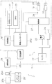
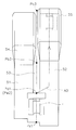
- FIG. 7 is a block diagram showing the configurations of a drive system and a control system of a work machine according to a first modified example.
- FIG. 7 is a block diagram showing the configurations of a drive system and a control system of a work machine according to a first modified example. It is a figure which shows operation
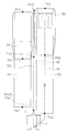
- FIG. 1 is a side view showing a working machine 1 according to the embodiment.
- the work machine 1 according to the present embodiment is a bulldozer.
- the work machine 1 includes a vehicle body 11, a traveling device 12, and a work machine 13.
- the vehicle body 11 includes a driver's cab 14 and an engine compartment 15.
- a driver's seat (not shown) is arranged in the cab 14.
- the engine compartment 15 is arranged in front of the cab 14.
- the traveling device 12 is attached to the lower portion of the vehicle body 11.
- the traveling device 12 includes a pair of left and right crawler belts 16. In FIG. 1, only the crawler belt 16 on the left side is shown.
- the work machine 1 travels as the crawler belt 16 rotates.
- the work machine 13 is attached to the vehicle body 11.
- the work machine 13 includes a lift frame 17, a blade 18, a lift cylinder 19, and a tilt cylinder 20.
- the lift frame 17 is attached to the vehicle body 11 so as to be vertically movable around an axis X extending in the vehicle width direction.
- the lift frame 17 supports the blade 18.
- Blade 18 is arranged in front of vehicle body 11.
- the blade 18 moves up and down as the lift frame 17 moves up and down.
- the lift frame 17 may be attached to the traveling device 12.
- the lift cylinder 19 is connected to the vehicle body 11 and the lift frame 17. As the lift cylinder 19 expands and contracts, the lift frame 17 moves up and down about the axis X.
- the tilt cylinder 20 is connected to the lift frame 17 and the blade 18. As the tilt cylinder 20 expands and contracts, the blade 18 tilts about the axis Z extending in the substantially front-back direction of the work machine 1.
- FIG. 2 is a block diagram showing the configuration of the drive system 2 and the control system 3 of the work machine 1.
- the drive system 2 includes an engine 22, a hydraulic pump 23, and a power transmission device 24.
- the hydraulic pump 23 is driven by the engine 22 and discharges hydraulic oil.
- the hydraulic oil discharged from the hydraulic pump 23 is supplied to the lift cylinder 19 and the tilt cylinder 20.
- one hydraulic pump 23 is shown in FIG. 2, a plurality of hydraulic pumps may be provided.
- the power transmission device 24 transmits the driving force of the engine 22 to the traveling device 12.
- the power transmission device 24 may be, for example, an HST (Hydro Static Transmission).
- the power transmission device 24 may be, for example, a torque converter or a transmission having a plurality of transmission gears.
- the control system 3 includes an operating device 25a, an input device 25b, a controller 26, a storage device 28, and a control valve 27.
- the operation device 25a and the input device 25b are arranged in the cab 14.
- the operation device 25a is a device for operating the work machine 13, the traveling device 12, the engine 22, and the power transmission device 24.
- the operating device 25a is arranged in the cab 14.
- the operation device 25a accepts an operation by the operator for driving the work machine 13 and outputs an operation signal according to the operation.
- the operation device 25a receives an operation by the operator for causing the work machine 1 to travel, and outputs an operation signal according to the operation.
- the operation signal of the operating device 25a is output to the controller 26.
- the operation device 25a includes, for example, an operation lever, a pedal, a switch, and the like.
- the input device 25b is a device for setting automatic control of the work machine 1 described later.
- the input device 25b receives an operation by an operator and outputs an operation signal according to the operation.
- the operation signal of the input device 25b is output to the controller 26.
- the input device 25b includes, for example, a touch panel type display.
- the input device 25b is not limited to the touch panel, and may include a hardware key.
- the controller 26 is programmed to control the work machine 1 based on the acquired data.
- the controller 26 includes a processing device (processor) 26a such as a CPU and a memory 26b.
- the memory 26b may include a volatile memory such as a RAM or a non-volatile memory such as a ROM.
- the controller 26 acquires an operation signal from the operation device 25a and the input device 25b.
- the controller 26 drives the work machine 1 by controlling the traveling device 12, the engine 22, and the power transmission device 24 according to the operation signal.
- the controller 26 operates the working machine 13 by controlling the control valve 27 according to the operation signal.
- the control valve 27 is a proportional control valve and is controlled by a command signal from the controller 26.
- the control valve 27 is arranged between a hydraulic actuator such as the lift cylinder 19 and the tilt cylinder 20 and the hydraulic pump 23.
- the control valve 27 controls the flow rate of the hydraulic oil supplied from the hydraulic pump 23 to the lift cylinder 19 or the tilt cylinder 20.
- the controller 26 generates a command signal to the control valve 27 so as to expand and contract the lift cylinder 19 or the tilt cylinder 20. This controls the operation of the blade 18.
- the control valve 27 may be a pressure proportional control valve. Alternatively, the control valve 27 may be an electromagnetic proportional control valve.
- the control system 3 includes a work machine sensor 29.
- the work implement sensor 29 detects the position of the work implement 13 with respect to the vehicle body 11 and generates work implement position data indicating the position of the work implement 13.
- the work implement sensor 29 may be a displacement sensor that detects the displacement of the work implement 13.
- the work machine sensor 29 may include a sensor that detects the stroke length of the lift cylinder 19.
- the controller 26 may calculate the lift angle of the blade 18 based on the stroke length of the lift cylinder 19.
- the work machine sensor 29 may include a sensor that detects the stroke length of the tilt cylinder 20.
- the controller 26 may calculate the tilt angle of the blade 18 based on the stroke length of the tilt cylinder 20.
- the control system 3 includes a load sensor 34.
- the load sensor 34 detects the load applied to the work machine 13 and generates load data indicating the load.
- the load sensor 34 is, for example, a pressure sensor that detects the hydraulic pressure of the lift cylinder 19.
- the load sensor 34 may be a sensor that detects parameters other than the hydraulic pressure of the lift cylinder 19.
- the load sensor 34 may be a sensor that detects the traction force of the work machine 1.
- the load sensor 34 may be a sensor that detects the magnitude of slip of the traveling device 12.
- the control system 3 includes a position sensor 31.
- the position sensor 31 measures the position of the work machine 1.
- the position sensor 31 includes a GNSS (Global Navigation Satellite System) receiver 32 and an IMU (Inertial Measurement Unit) 33.
- the GNSS receiver 32 is, for example, a receiver for GPS (Global Positioning System).
- GPS Global Positioning System
- the antenna of the GNSS receiver 32 is arranged on the cab 14. However, the antenna of the GNSS receiver 32 may be arranged at another position.
- GNSS receiver 32 receives a positioning signal from a satellite, calculates the position of the antenna based on the positioning signal, and generates machine position data indicating the position of vehicle body 11.
- the controller 26 obtains machine position data from the GNSS receiver 32.
- the controller 26 acquires the current position of the work machine 1, the traveling direction of the work machine 1, and the vehicle speed from the machine position data.
- the IMU33 acquires vehicle body inclination angle data.
- the vehicle body inclination angle data includes an angle (pitch angle) with respect to the horizontal in the front-rear direction of the work machine 1 and an angle (roll angle) with respect to the horizontal in the work machine 1.
- the controller 26 acquires the vehicle body inclination angle data from the IMU 33.
- the controller 26 calculates the blade tip position Pb of the blade 18 from the work machine position data, the machine position data, and the vehicle body tilt angle data. For example, controller 26 obtains global coordinates of GNSS receiver 32 based on machine position data. The controller 26 calculates the local coordinates of the cutting edge position Pb with respect to the GNSS receiver 32 based on the work machine position data. The controller 26 calculates the global coordinates of the cutting edge position Pb based on the global coordinates of the GNSS receiver 32, the local coordinates of the cutting edge position Pb, and the vehicle body inclination angle data. The controller 26 acquires the global coordinates of the cutting edge position Pb as the current position data of the working machine 13.
- the storage device 28 may be a semiconductor memory, a hard disk, or the like.
- the storage device 28 is an example of a non-transitory computer-readable recording medium.
- the storage device 28 stores computer instructions executable by the processor to control the work machine 1.
- the automatic control of the work machine 1 may be a semi-automatic control performed in combination with a manual operation by an operator.
- the automatic control of the work machine 1 may be fully automatic control performed without manual operation by the operator.
- the controller 26 automatically controls the work machine 1 based on the current terrain data, the design terrain data, and the current position data.
- the current terrain data and the design terrain data are stored in the storage device 28.
- the current terrain data shows the current terrain 50 of the work site.
- the current terrain data is information indicating the current terrain of the work site located in the traveling direction of the work machine 1.
- FIG. 3 shows a cross section of the current terrain 50.
- the vertical axis represents the height of the terrain
- the horizontal axis represents the distance from the current position in the traveling direction of the work machine 1.
- the plurality of reference points Pn indicate a plurality of points at predetermined intervals along the traveling direction of the work machine 1.
- the predetermined interval may be 1 m, for example. However, the predetermined interval may be smaller than 1 m or may be larger than 1 m.
- the current terrain data may be acquired from an external device and stored in the storage device 28.
- the current terrain data may be acquired by the controller 26 recording the trajectory of a part of the work machine 1 such as the cutting edge position Pb or the crawler belt 16 or the like.
- the current terrain data may be acquired from distance measurement of the current terrain 50 by a vehicle-mounted lidar (LIDAR: Laser Imaging Detection and Ranging) or the like.
- LIDAR Laser Imaging Detection and Ranging
- the design topography data indicates the target design topography 70.
- the target design topography 70 indicates the target trajectory of the cutting edge of the blade 18 in the work.
- the target design terrain 70 indicates a terrain desired as a result of the work performed by the work implement 13. Similar to the current terrain 50, the target design terrain 70 is represented by the height Zn of the target design terrain 70 at a plurality of reference points Pn.
- the target design terrain 70 may be generated by the controller 26 based on the current terrain data. Alternatively, the target design terrain 70 may be generated by the controller 26 based on the capabilities of the work machine 1, such as the capacity of the blades 18. Alternatively, the target design terrain 70 may be obtained from an external device.
- the controller 26 selectively executes the normal excavation mode and the wall excavation mode.
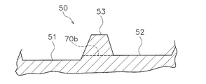
- the normal excavation mode is a control mode for excavating the existing terrain 50, as shown in FIG.
- the normal excavation mode forms slots 51, 52 in the existing terrain 50.
- the wall excavation mode is a control mode for excavating the excavation wall 53 formed between the plurality of slots 51, 52.
- the controller 26 may execute another control mode different from the normal excavation mode and the wall excavation mode.
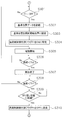
- FIG. 5 is a flowchart showing the process of automatic control in the normal excavation mode.
- the controller 26 acquires a start command for the normal excavation mode.
- the normal excavation mode may be selected by the operator operating the input device 25b. That is, the controller 26 may determine execution of the normal excavation mode based on the operation signal from the input device 25b.
- a preset construction plan may be stored in the storage device 28, and the controller 26 may determine execution of the normal excavation mode according to the construction plan.
- the controller 26 may determine execution of the normal excavation mode by determining whether a predetermined start condition is satisfied, based on a parameter such as the shape of the current topography 50.
- step S102 the controller 26 acquires the above-mentioned current position data.
- the controller 26 continuously acquires and updates the current position data even during execution of the process described below.
- step S103 the controller 26 acquires the above-mentioned current terrain data.
- FIG. 6 is a diagram showing an example of the current terrain 50 in the normal excavation mode.
- step S104 the controller 26 acquires work range data.
- the working range includes the start and end of excavation.
- the work range data includes start position data and end position data for excavation.
- the excavation start end position data indicates the position of the excavation start end.
- the excavation end position data indicates the position of the end of excavation.
- the position of the start and end of excavation may be set by the input device 25b.
- the position of the starting end of the excavation and the length of the excavating range may be set by the input device 25b, and the position of the ending end of the excavation may be determined by calculation.
- the position of the end of excavation and the length of the excavation range may be set by the input device 25b, and the position of the starting end of excavation may be determined by calculation.
- the work range also includes the end position of the soil. Placement is the work of discharging the soil excavated and held by the blade 18 onto the existing terrain 50.
- the work range data includes the end position data of the soil.
- the end position data of the earth deposit indicates the end position of the earth deposit.
- the position of the end of the soil may be set by the input device 25b.
- the length of the soil placing range may be set by the input device 25b, and the position of the end of the soil placing may be determined by calculation.
- the controller 26 acquires work range data based on the operation signal from the input device 25b.
- the controller 26 may acquire the work range data by another method.
- the controller 26 may acquire the work range data from an external device.
- step S105 the controller 26 acquires design topography data.
- the controller 26 determines the target design topography 70a as shown in FIG.
- the target design topography 70a includes a first target topography 71a and a second target topography 72a. At least a part of the first target topography 71a is located below the current topography 50. At least a part of the second target landform 72a is located above the current landform 50.
- the controller 26 may determine the target design terrain 70a according to the current terrain 50. For example, the controller 26 may determine the first target landform 71a so as to be located below the current landform 50 by a predetermined distance. The controller 26 may determine the first target landform 71a so that the first target landform 71a is inclined at a predetermined angle with respect to the current landform 50 or the horizontal direction.
- the controller 26 may determine the second target terrain 72a so as to be located above the current terrain 50 by a predetermined distance.
- the controller 26 may determine the second target landform 72a so as to be inclined with respect to the current landform 50 or at a predetermined angle with respect to the horizontal direction.
- the target design topography 70a may be determined in advance.
- step S106 the controller 26 starts excavation.
- the controller 26 controls the work machine 1 according to the target design topography 70a.
- the controller 26 advances the work machine 1 from the start end to the end of the excavation and controls the work machine 13 so that the blade tip position of the blade 18 moves according to the first target landform 71a.
- the current landform 50 is excavated by moving the cutting edge of the blade 18 along the first target landform 71a.
- slots 51 and 52 as shown in FIG. 4 are formed in the existing terrain 50.
- the controller 26 advances the work machine 1 from the end of excavation to the end of soil placement and controls the work machine 13 so that the blade tip position of the blade 18 moves according to the second target landform 72a.
- the controller 26 advances the work machine 1 from the end of excavation to the end of soil placement and controls the work machine 13 so that the blade tip position of the blade 18 moves according to the second target landform 72a.
- the soil excavated and held by the blade 18 is placed on the existing landform 50.
- the earth deposits 54 and 55 piled up on the existing terrain 50 are formed.
- the controller 26 may set a plurality of excavation start positions Ps1 to Ps3 between the excavation start end and the excavation end.
- the controller 26 may perform the excavation from the excavation start position Ps1 near the end, and then perform the excavation in the order of the excavation start positions Ps2 and Ps3.
- the controller 26 controls the work machine 1 so that the excavation is started from the first start position Ps1 toward the end of the excavation, and the soil is placed beyond the end of the excavation toward the end of the soil.
- the controller 26 retracts the work machine 1 to the second start position Ps2.
- the controller 26 controls the work machine 1 so as to start excavation from the second start position Ps2 and perform excavation and soil placement in the same manner as above.
- the controller 26 retracts the work machine 1 to the third start position Ps3.
- the controller 26 controls the work machine 1 so as to start excavation from the third start position Ps3 and perform excavation and soil placement in the same manner as above.
- step S107 the controller 26 updates the current topographical data.
- the controller 26 updates the current terrain data with the position data indicating the latest trajectory of the cutting edge position Pb.
- the controller 26 may calculate the position of the bottom surface of the crawler belt 16 and update the current terrain data with the position data indicating the trajectory of the bottom surface of the crawler belt 16.
- the current terrain data may be updated with the survey data measured by the surveying device outside the work machine 1.
- an external surveying instrument for example, aerial laser surveying may be used.
- the current terrain 50 may be photographed by the camera, and the work site terrain data may be generated from the image data obtained by the camera.
- UAV Unmanned Aerial Vehicle
- the update of the current terrain data may be performed at predetermined intervals or at any time.
- the work from the start of excavation to the end of soil placement is regarded as one unit of work, and when one unit of work is completed, the controller 26 moves the work machine 1 to the side of the already formed first slot 51. Then, the next second slot 52 is formed by performing the processing of steps S101 to S107 described above again.
- the controller 26 moves the work machine 1 to the side and is adjacent to the side of the first slot 51.
- the work machine 1 is operated so as to form the second slot 52 that is formed.
- the controller 26 may start the formation of the second slot 52 after repeating the operation of a plurality of units to form the first slot 51.
- step S108 the controller 26 determines whether to finish excavation.
- the controller 26 may determine the end of excavation according to the operation of the input device 25b.
- the controller 26 may determine the end of excavation according to a preset construction plan.
- the controller 26 may determine the end of excavation by determining whether a predetermined end condition is satisfied.
- the controller 26 laterally moves the work machine 1 larger than the width of the blade 18. Therefore, as shown in FIG. 4, the excavation wall 53 is formed between the first slot 51 and the second slot 52.
- the excavation wall 53 is a berms of soil along the slots 51, 52.
- FIG. 7 is a flowchart showing the process of automatic control in the wall excavation mode.
- the controller 26 acquires a start command for the wall excavation mode.
- the wall excavation mode may be selected by the operator operating the input device 25b. That is, the controller 26 may determine execution of the wall excavation mode based on the operation signal from the input device 25b.
- the controller 26 may determine execution of the wall excavation mode according to a preset construction plan. Alternatively, the controller 26 may determine whether to execute the wall excavation mode by determining whether a predetermined start condition is satisfied.
- step S202 the controller 26 acquires the current position data, as in step S102.
- the controller 26 continuously acquires and updates the current position data even during execution of the process described below.
- step S203 the controller 26 acquires the current terrain data.
- FIG. 8 is a diagram showing an example of the excavation wall 53 included in the current topography 50 as viewed from the vehicle width direction.
- FIG. 9 is a diagram showing an example of the current terrain 50 viewed from the traveling direction of the work machine 1.
- the current terrain data includes the first slot position data, the second slot position data, and the excavation wall position data.
- the first slot position data indicates the position of the first slot 51.
- the second slot position data indicates the position of the second slot 52.
- the excavation wall position data indicates the position of the excavation wall 53.
- step S204 the controller 26 acquires work range data.
- the working range includes the start and end of excavation.
- the work range data includes excavation start position data and excavation end position data.
- the excavation start end position data indicates the position of the excavation start end.
- the excavation end position data indicates the position of the end of excavation.
- Figure 10 is a view of the current terrain 50 as seen from above.
- the controller 26 determines the position Pa3 of the starting end of the excavation of the excavation wall 53 from the position Pa1 of the starting end of the excavation of the first slot 51 and the position Pa2 of the starting end of the excavation of the second slot 52. To do.
- the controller 26 calculates an intermediate position between the position Pa1 of the starting end of the excavation of the first slot 51 and the position Pa2 of the starting end of the excavation of the second slot 52.
- the controller 26 determines the calculated intermediate position as the position Pa3 of the excavation start end of the excavation wall 53.
- controller 26 in plan view, the position of the starting point Pa1 of the excavation of the first slot 51 and the position Pa2 of the starting end of the excavation of the second slot 52, the midpoint of the straight line, the excavation of the excavation wall 53 It is decided as the position Pa3 of the start end of
- the controller 26 determines the position Pb3 of the end of excavation of the excavation wall 53 from the position Pb1 of the end of excavation of the first slot 51 and the position Pb2 of the end of excavation of the second slot 52. For example, the controller 26 calculates an intermediate position between the position Pb1 of the end of excavation of the first slot 51 and the position Pb2 of the end of excavation of the second slot 52. The controller 26 determines the calculated intermediate position as the position Pb3 at the end of excavation of the excavation wall 53. That is, the controller 26, in plan view, the position of the straight line connecting the end position Pb1 of the excavation of the first slot 51 and the end position Pb2 of the excavation of the second slot 52, the excavation of the excavation wall 53 Is determined as the end position Pb3.
- the work range includes the end of the soil.
- the work range data includes the end position data of the soil.
- the end position data of the earth deposit indicates the end position of the earth deposit.
- the controller 26 determines from the position Pc1 of the end of the earth deposit of the first slot 51 and the position Pc2 of the end of the earth deposit of the second slot 52 to the position of the end of the earth deposit of the excavation wall 53. Determine Pc3.
- the controller 26 calculates an intermediate position between the position Pc1 of the end of the soil placement in the first slot 51 and the position Pc2 of the end of the soil placement in the second slot 52.
- the controller 26 determines the calculated intermediate position as the position Pc3 of the end of the soil deposit on the excavation wall 53. That is, the controller 26, when viewed in plan, the position of the straight line connecting the end position Pc1 of the soil placement of the first slot 51 and the end position Pc2 of the soil placement of the second slot 52, the excavation wall 53 It is decided as the position Pc3 of the end of the soil.
- step S205 the controller 26 acquires design topography data.
- the controller 26 determines the target design topography 70b of the excavation wall 53 as shown in FIG.
- the target design topography 70b includes a first target topography 71b and a second target topography 72b. At least a part of the first target landform 71b is located below the excavation wall 53. At least a part of the second target landform 72b is located above the excavation wall 53. However, the second target landform 72b may be located below the excavation wall 53 when it is dropped below a cliff and discharged.
- the controller 26 determines the target excavation height of the excavation wall 53 from the height of the first slot 51 and the height of the second slot 52.
- the controller 26 determines the target design topography 70 from the target excavation height. Specifically, as shown in FIG. 9, the controller 26 controls the height of the excavation wall 53 from the higher height of the first slot 51 and the second slot 52 (the height of the second slot 52 in FIG. 9). Determine the target excavation height. That is, the controller 26 determines the target excavation height of the excavation wall 53 according to the higher height of the first slot 51 and the second slot 52. Then, the controller 26 determines the target design topography 70b from the target excavation height of the excavation wall 53.
- step S206 the controller 26 sets the excavation start position Pa3 of the excavation wall 53 acquired in step S204 to the excavation start position Pw1.
- the controller 26 may set the excavation start position Pw1 to another position determined based on the start end position Pa3, not limited to the start end position Pa3 of the excavation wall 53.
- the controller 26 may set, as the excavation start position Pw1, a position away from the position Pa3 of the excavation start end of the excavation wall 53 by a predetermined distance.
- step S207 the controller 26 sets the load control executed flag F1 to “OFF”.
- the load control executed flag F1 is a flag indicating whether or not load control, which will be described later, has been executed.
- the fact that the load control executed flag F1 is "OFF” indicates that the load control has not been executed yet.
- the fact that the load control executed flag F1 is "ON” indicates that the load control has already been executed.
- step S208 the controller 26 moves the work machine 1 to the excavation start position Pw1.
- the controller 26 may move the work machine 1 onto the excavation wall 53 after retracting the work machine 1 along the second slot 52, as indicated by an arrow A1 in FIG.
- the controller 26 may move the work machine 1 onto the excavation wall 53 and then retract the work machine 1 along the excavation wall 53.
- step S209 the controller 26 starts excavation of the excavation wall 53.
- the controller 26 controls the work machine according to the target design topography 70b of the excavation wall 53. Specifically, the controller 26 advances the work machine 1 from the excavation start position Pw1 toward the end point Pb3 of the excavation as shown by an arrow A2 in FIG. 11, and the cutting edge of the blade 18 according to the first target landform 71b.
- the working machine 13 is controlled so that the position moves.
- the cutting edge of the blade 18 moves along the first target landform 71b, whereby the excavation wall 53 of the existing landform 50 is excavated.
- the controller 26 advances the work machine 1 from the position Pb3 at the end of excavation to the position Pc3 at the end of soil placement, and at the same time, the work machine 13 moves the blade tip position of the blade 18 according to the second target landform 72b.
- the soil excavated and held by the blade 18 is placed on the existing landform 50.
- the gap between the set soil 54 corresponding to the first slot 51 and the set soil 55 corresponding to the second slot 52 is filled with the excavated soil.
- step S210 the controller 26 determines whether the load on the work machine 13 is smaller than the first threshold Th1.
- the first threshold Th1 is stored in the storage device 28.
- the first threshold Th1 may be a fixed value.
- the first threshold Th1 may be variable.
- the first threshold Th1 is a value that can prevent the work machine 1 or the work machine 13 from becoming inoperable.
- the process proceeds to step S211.
- step S211 the controller 26 determines whether to finish excavation of the excavation wall 53.
- the controller 26 may determine the end of excavation of the excavation wall 53 when the work machine 1 reaches the end of the soil placement.
- the controller 26 may determine the end of excavation of the excavation wall 53 according to the operation of the input device 25b.
- the controller 26 may determine the end of excavation of the excavation wall 53 according to a preset construction plan.
- the controller 26 updates the current terrain data as in step S107.
- step S210 when the load on the work implement 13 is equal to or larger than the first threshold Th1, the process proceeds to step S301 shown in FIG.
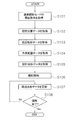
- FIG. 12 is a flowchart showing the processing of load reduction control.
- the controller 26 executes the load reduction control process shown in FIG. 12 when the load applied to the work implement 13 during excavation becomes equal to or higher than the first threshold Th1.
- the controller 26 operates the work machine 1 so as to reduce the load applied to the work machine 13.
- the controller 26 raises the working machine 13 to reduce the load on the working machine 13.
- step S301 the controller 26 determines whether the load control executed flag F1 is “OFF”. When the load control executed flag F1 is "OFF”, the process proceeds to step S302.
- step S302 the controller 26 records the reference position data.
- the controller 26 records the position of the work machine 1 at the start of execution of the load reduction control as the reference position.
- the controller 26 records the position where the cutting edge of the blade 18 is away from the target design topography 70b as the reference position Pd1.
- step S303 the controller 26 sets the reference position Pd1 to the next excavation start position Pw2.
- the controller 26 is not limited to the reference position Pd1 itself, and may set another position as the next excavation start position Pw2.
- the controller 26 may set a position away from the reference position Pd1 by a predetermined distance as the next excavation start position Pw2.
- step S304 the controller 26 sets the load control executed flag F1 to “ON”.
- step S305 the controller 26 starts the departure from the target design topography 70b.
- the controller 26 raises the working machine 13 as shown by a locus 73a in FIG. That is, the controller 26 raises the cutting edge of the blade 18. It is assumed that the controller 26 continues to move the work machine 1 forward from step S305 to step S309.
- step S306 the controller 26 determines whether the load on the work machine 13 is smaller than the second threshold Th2.
- the second threshold Th2 is smaller than the first threshold Th1. That is, the second threshold Th2 is a value indicating that the load on the work machine 13 has been reduced.
- the controller 26 continues to separate until the load on the work machine 13 becomes smaller than the second threshold Th2. That is, the controller 26 continues to raise the working machine 13 until the load on the working machine 13 becomes smaller than the second threshold Th2.
- the controller 26 ends the withdrawal in step S307.
- step S308 the controller 26 determines whether the load on the work machine 13 is smaller than the first threshold Th1. When the load on the work machine 13 is smaller than the first threshold Th1, the process proceeds to step S309.
- step S309 the controller 26 determines whether or not the work machine 1 has reached the folding position.
- the folding-back position is, for example, a position where the work machine 1 has crossed the end of excavation and piled up the soil held in the work machine 13 at a position between the end of excavation and the end of placed soil.
- the folding position may be a position between the end of excavation and the end of soil placement.
- the folding-back position may be the position of the end of the soil placement.
- step S310 the controller 26 sets the load control executed flag F1 to “OFF”. Then, the process returns to step S208.
- step S208 the controller 26 moves the work machine 1 to the excavation start position Pw2.
- the excavation start position Pw2 is the above-mentioned reference position Pd1. Therefore, the work machine 1 moves back to the reference position Pd1.
- step S209 the controller 26 starts excavation of the excavation wall 53 again.
- the controller 26 starts the excavation from the excavation start position Pw2, that is, the reference position Pd1, and controls the work machine 1 so that the work machine 13 operates according to the target design topography 70b.
- step S211 when the controller 26 determines to end the excavation of the excavation wall 53, the controller 26 ends the processing in the wall excavation mode.
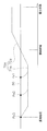
- first start position Pw1 the work machine 1 starts the first excavation from the excavation start position Pw1 (hereinafter, “first start position Pw1”).
- first start position Pw1 the load applied to the work implement 13 becomes equal to or larger than the first threshold Th1
- the controller 26 starts the load reduction control and raises the work implement 13 as indicated by the trajectory 73a. Further, the controller 26 records the position of the work machine 1 when the load reduction control is started as the reference position Pd1.
- the controller 26 holds the cutting edge of the working machine 13 at the height at that time and excavates as shown by a locus 74a. Continue. The excavation ends when the cutting edge of the working machine 13 merges with the target design topography 70b and reaches the end of excavation. Then, the work machine 1 is further advanced to perform soiling, and the first excavation is completed.
- the controller 26 retracts the work machine 1 to move it to the excavation start position Pw2 (hereinafter, “second start position Ps2”). Then, the work machine 1 is controlled so as to start the second excavation from the second start position Ps2.
- the controller 26 operates the work implement 13 according to the target design surface 70b to perform excavation and soil placement. Then, when the controller 26 determines to end the excavation of the excavation wall 53, the processing in the wall excavation mode ends.
- step S308 if the load on the work implement 13 becomes equal to or higher than the first threshold Th1 again, the process returns to step S301.
- the load control executed flag is "ON"
- the process proceeds from step S301 to step S305. Therefore, the reference position data of step S302 is not recorded and the reference position of step S303 is not set as the excavation start position, and the process proceeds to step S305.
- step S305 the controller 26 raises the work implement 13 to start the disengagement. Then, when the load on the work implement 13 becomes smaller than the second threshold value Th2 (step S306), the controller 26 ends the detachment and continues the first excavation in step S307.
- step S302 is recorded, and the reference position of step S303 is the excavation start position.
- step S305 to step S307 is repeated.
- load reduction control is started at a plurality of reference positions Pd1, Pd2, Pd3 during the first excavation.
- the first reference position Pd1 is recorded as the second start position Ps2.
- step S309 the controller 26 sets the load control executed flag F1 to "OFF" in step S310, and the process returns to step S208.
- step S208 the controller 26 moves the work machine 1 to the reference position Pd1. Then, the controller 26 starts the second excavation from the reference position Pd1.
- the controller 26 executes the load reduction control when the load applied to the work machine 13 during the first excavation becomes excessive. As a result, the load on the work machine 13 is reduced. Further, when the load reduction control is executed, the controller 26 records the position of the work machine 1 at the start of the execution of the load reduction control as the reference position Pd1, and determines the second start position Ps2 based on the reference position Pd1. Then, the second excavation is started from the second start position Ps2. Therefore, even when the load reduction control is executed, the excavation with good finish quality can be performed by the automatic control of the work machine 1.
- the controller 26 determines the second start position Ps2 based on the first reference position Pd1 among the plurality of reference positions Pd1-Pd3 when the load reduction control is executed a plurality of times during the first excavation. Therefore, as compared with the case where the second excavation is started from the second and subsequent reference positions Pd2 and Pd3, the work can be performed efficiently.
- the work machine is not limited to a bulldozer, but may be another work machine such as a wheel loader, a motor grader, or a hydraulic excavator.
- the work machine may be a machine driven by an electric motor.
- Existing terrain may include material such as coal or iron ore.
- the work machine may be a machine that can be remotely controlled. In that case, part of the control system may be located outside the work machine.
- the controller may be located external to the work machine.
- the controller may be located in a control center remote from the work site. In that case, the work machine may be a machine without a cab.
- the controller may have a plurality of controllers separate from each other.
- the controller 26 may include a remote controller 261 arranged outside the work machine and an in-vehicle controller 262 mounted on the work machine.
- the remote controller 261 and the in-vehicle controller 262 may be capable of wirelessly communicating with each other via the communication devices 38 and 39. Then, a part of the functions of the controller 26 described above may be executed by the remote controller 261, and the remaining functions may be executed by the in-vehicle controller 262.
- the remote controller 261 executes the process of determining the target design topography 70, 70a, 70b, and the in-vehicle controller 262 executes the process of outputting a command signal to the traveling device 12, the work machine 13, the engine 22, the power transmission device 24, and the like. It may be executed.
- the operation device 25a and the input device 25b may be arranged outside the work machine. In that case, the cab may be omitted from the work machine. Alternatively, the operating device 25a and the input device 25b may be omitted from the work machine.
- the current terrain 50 is not limited to the position sensor 31 described above, and may be acquired by another device.
- the current terrain 50 may be acquired by the interface device 37 that receives data from an external device.
- the interface device 37 may wirelessly receive the current terrain data measured by the external measuring device 41.
- the interface device 37 may be a recording medium reading device, and may accept the current topographical data measured by the external measuring device 41 via the recording medium.
- the method of determining the target design terrain 70, 70a, 70b is not limited to that of the above embodiment, and may be changed.
- the controller 26 may determine the target design topography 70, 70a, 70b based on parameters such as the load on the work machine 13, the target angle, and the target position. Alternatively, the target design topography 70, 70a, 70b may be determined in advance by a construction plan.
- the work stroke in the normal excavation mode and the wall excavation mode is not limited to that in the above-described embodiment.
- the excavation of the excavation wall 53 between the two slots 51 and 52 is performed after the two slots 51 and 52 are formed.
- excavation of the plurality of cut walls between the slots may be performed.
- the work range data may be set by the operator operating the input device 25b.
- the controller 26 as a position of the starting end of the excavation of the first slot 51, or a position lateral to the starting end of the excavation of the second slot 52, as the starting end position of the excavation of the excavation wall 53. You may decide.
- the controller 26 determines either the position on the side of the end of the excavation of the first slot 51 or the position on the side of the end of the excavation of the second slot 52 as the position of the end of the excavation on the excavation wall 53. May be.
- the controller 26 determines the position of the earthing end of the excavation wall 53 as one of the position on the side of the end of the earthing of the first slot 51 and the position on the side of the end of the earthing of the second slot 52. May be determined as
- the controller 26 may determine the target excavation height of the excavation wall 53 from the lower height of the first slot 51 and the second slot 52. Alternatively, the controller 26 may determine the target excavation height of the excavation wall 53 from the intermediate value of the heights of the first slot 51 and the second slot 52.
- the controller 26 executes the load reduction control in the wall excavation mode.
- the controller 26 may execute the load reduction control in a control mode other than the wall excavation mode.
- the controller 26 may execute the load reduction control in the normal excavation mode.
- the controller 26 may record, as the reference position Pd1, the position when the load applied to the work machine 13 becomes equal to or higher than another threshold different from the first threshold Th1.
- the other threshold may be a value smaller than the first threshold Th1 described above.
- the controller 26 reduces the load on the work machine 13 by raising the work machine 13 in the load reduction control.
- the controller 26 may reduce the load on the work machine 13 by another method. For example, when the load is equal to or more than the first threshold Th1, the controller 26 moves the work machine 1 to the adjacent first slot 51 or second slot 52, as shown by an arrow A3 in FIG. 17, to reduce the load. May be reduced.
- FIG. 18 is a flowchart showing a process of load reduction control according to the modification.
- steps S401 to S404 are the same as steps S301 to S304 in FIG. 12 described above.
- the controller 26 determines whether the height of the excavation wall 53 is smaller than the third threshold Th3.
- the height of the excavation wall 53 is, for example, the vertical distance between the bottom surface of the adjacent slot and the top of the excavation wall 53.
- step S406 If the height of the excavation wall 53 is smaller than the third threshold Th3, the process proceeds to step S406.
- Steps S406 to S411 are the same as steps S305 to S310 of FIG. 12 described above. Therefore, when the height of the excavation wall 53 is smaller than the third threshold value Th3, the controller 26 raises the work implement 13 to reduce the load on the work implement 13.
- step S405 when the height of the excavation wall 53 is the third threshold value Th3 or more, the process proceeds to step S412.
- step S412 the controller 26 disengages the working machine 13 by moving the working machine 1 to the first slot 51 or the second slot 52 adjacent to the excavation wall 53. As a result, the load on the work machine 13 is reduced.
- controller 26 may determine to which slot the work machine 1 moves in accordance with the operation of the input device 25b by the operator. Alternatively, the controller 26 may determine to which slot the work machine 1 moves, depending on the positions of the first slot 51 and the second slot 52, or conditions such as the presence or absence of another vehicle.
- the controller 26 moves the work machine 1 to the first slot 51 or the second slot 52, and then further advances the work machine 1 on the slot to execute soil placement. Then, in step S411, the controller 26 sets the load control execution flag F1 to “OFF”. Then, the process returns to step S208. Subsequent processing is the same as that of the above-mentioned embodiment.
- excavation with good finish quality can be performed by automatic control of the work machine.
Landscapes
- Engineering & Computer Science (AREA)
- Mining & Mineral Resources (AREA)
- Civil Engineering (AREA)
- General Engineering & Computer Science (AREA)
- Structural Engineering (AREA)
- Radar, Positioning & Navigation (AREA)
- Mechanical Engineering (AREA)
- Aviation & Aerospace Engineering (AREA)
- Remote Sensing (AREA)
- Physics & Mathematics (AREA)
- General Physics & Mathematics (AREA)
- Automation & Control Theory (AREA)
- Operation Control Of Excavators (AREA)
Abstract
Description
13 作業機
26 コントローラ
31 位置センサ
34 負荷センサ
51 第1スロット
52 第2スロット
53 掘削壁
Claims (18)
- 作業機を含む作業機械を制御するためのシステムであって、
前記作業機にかかる負荷を示す負荷データを検出する負荷センサと、
前記負荷データを取得するプロセッサと、
を備え、
前記プロセッサは、
掘削中に前記作業機にかかる負荷に基づいて、前記負荷を軽減するように前記作業機械を動作させる負荷軽減制御を実行し、
前記掘削中に前記作業機にかかる負荷が所定の閾値以上になったときの前記作業機械の位置を基準位置として記録し、
前記基準位置に基づいて次の開始位置を決定し、
前記次の開始位置から次の掘削を開始するように前記作業機械を制御する、
システム。 - 前記プロセッサは、
第1の掘削の第1の開始位置を取得し、
前記第1の開始位置から前記作業機によって前記第1の掘削を開始するように前記作業機械を制御し、
前記第1の掘削中に前記作業機にかかる負荷に基づいて、前記負荷軽減制御を実行し、
前記第1の掘削中に前記作業機にかかる負荷が所定の閾値以上になったときの前記作業機械の位置を前記基準位置として記録し、
前記基準位置に基づいて第2の開始位置を決定し、
前記第1の掘削の終了後、前記第2の開始位置から第2の掘削を開始するように前記作業機械を制御する、
請求項1に記載のシステム。 - 前記プロセッサは、
前記掘削中に前記作業機にかかる負荷が前記所定の閾値以上であるときに、前記負荷軽減制御を実行し、
前記負荷軽減制御の実行の開始時の前記作業機械の位置を前記基準位置として記録する、
請求項1に記載のシステム。 - 前記プロセッサは、前記掘削中に、複数回の前記負荷軽減制御を実行したときには、複数の前記負荷軽減制御の実行の開始時の前記作業機械の位置のうち、最初の位置に基づいて前記次の開始位置を決定する、
請求項3に記載のシステム。 - 前記プロセッサは、前記負荷軽減制御において、前記作業機を上昇させることで、前記負荷を軽減する、
請求項1に記載のシステム。 - 前記プロセッサは、
作業現場の現況地形を掘削する通常掘削モードと、前記現況地形の掘削により複数のスロットの間に形成された掘削壁を掘削する壁掘削モードとを選択的に実行し、
前記壁掘削モードにおいて、前記負荷軽減制御の実行の開始時の前記作業機械の位置を前記基準位置として記録し、前記基準位置に基づいて前記次の開始位置を決定し、前記次の開始位置から前記次の掘削を開始するように前記作業機械を制御する、
請求項3に記載のシステム。 - 前記プロセッサは、前記負荷が所定の閾値以上であるときには、前記作業機械を隣接する前記スロットに移動させることで、前記負荷を軽減する、
請求項6に記載のシステム。 - 前記プロセッサは、前記負荷軽減制御において、前記作業機を上昇させることと、前記作業機械を隣接する前記スロットに移動させることとを選択的に実行する、
請求項6記載のシステム。 - 前記プロセッサは、
前記掘削壁の高さを示す掘削壁データを取得し、
前記負荷軽減制御において、前記掘削壁の高さに基づいて、前記作業機を上昇させるか、又は、前記作業機械を隣接する前記スロットに移動させるかを決定する、
請求項8に記載のシステム。 - 作業機を含む作業機械を制御するためにプロセッサによって実行される方法であって、
前記作業機にかかる負荷を示す負荷データを取得することと、
掘削中に前記作業機にかかる負荷に基づいて、前記負荷を軽減するように前記作業機械を動作させる負荷軽減制御を実行することと、
前記掘削中に前記作業機にかかる負荷が所定の閾値以上になったときの前記作業機械の位置を基準位置として記録することと、
前記基準位置に基づいて次の開始位置を決定することと、
前記次の開始位置から次の掘削を開始するように前記作業機械を制御すること、
を備える方法。 - 第1の掘削の第1の開始位置を取得することと、
前記第1の開始位置から前記作業機によって前記第1の掘削を開始するように前記作業機械を制御することと、
前記第1の掘削中に前記作業機にかかる負荷に基づいて、前記負荷軽減制御を実行することと、
前記第1の掘削中に前記作業機にかかる負荷が所定の閾値以上になったときの前記作業機械の位置を前記基準位置として記録することと、
前記基準位置に基づいて第2の開始位置を決定することと、
前記第1の掘削の終了後、前記第2の開始位置から第2の掘削を開始するように前記作業機械を制御すること、
を備える請求項10に記載の方法。 - 前記掘削中に前記作業機にかかる負荷が前記所定の閾値以上であるときに、前記負荷軽減制御が実行され、
前記負荷軽減制御の実行の開始時の前記作業機械の位置が、前記基準位置として記録される、
請求項10に記載の方法。 - 前記次の開始位置を決定することは、前記掘削中に、複数回の前記負荷軽減制御を実行したときに、複数の前記負荷軽減制御の実行の開始時の前記作業機械の位置のうち、最初の位置に基づいて前記次の開始位置を決定することを含む、
請求項12に記載の方法。 - 前記負荷軽減制御は、前記負荷軽減制御において、前記作業機を上昇させることで、前記負荷を軽減することを含む、
請求項10に記載の方法。 - 作業現場の現況地形を掘削する通常掘削モードと、前記現況地形の掘削により複数のスロットの間に形成された掘削壁を掘削する壁掘削モードとを選択的に実行することをさらに備え、
前記壁掘削モードは、
前記負荷軽減制御の実行の開始時の前記作業機械の位置を前記基準位置として記録することと、
前記基準位置に基づいて前記次の開始位置を決定することと、
前記掘削の終了後、前記次の開始位置から前記第2の掘削を開始するように前記作業機械を制御すること、
を含む、
請求項12に記載の方法。 - 前記負荷軽減制御は、前記負荷が所定の閾値以上であるときには、前記作業機械を隣接する前記スロットに移動させることで、前記負荷を軽減することを含む、
請求項15に記載の方法。 - 前記負荷軽減制御は、前記作業機を上昇させることと、前記作業機械を隣接する前記スロットに移動させることとを選択的に実行することを含む、
請求項15に記載の方法。 - 前記掘削壁の高さを示す掘削壁データを取得することをさらに備え、
前記負荷軽減制御は、前記掘削壁の高さに基づいて、前記作業機を上昇させるか、又は、前記作業機械を隣接する前記スロットに移動させるかを決定することを含む、
請求項17に記載の方法。
Priority Applications (3)
| Application Number | Priority Date | Filing Date | Title |
|---|---|---|---|
| AU2019382333A AU2019382333B2 (en) | 2018-11-19 | 2019-09-17 | System and method for automatically controlling work machine including work implement |
| CA3111807A CA3111807C (en) | 2018-11-19 | 2019-09-17 | System and method for automatically controlling work machine including work implement |
| US17/273,387 US11899461B2 (en) | 2018-11-19 | 2019-09-17 | System and method for automatically controlling work machine including work implement |
Applications Claiming Priority (2)
| Application Number | Priority Date | Filing Date | Title |
|---|---|---|---|
| JP2018-216703 | 2018-11-19 | ||
| JP2018216703A JP2020084459A (ja) | 2018-11-19 | 2018-11-19 | 作業機を含む作業機械を自動制御するためのシステム及び方法 |
Publications (1)
| Publication Number | Publication Date |
|---|---|
| WO2020105261A1 true WO2020105261A1 (ja) | 2020-05-28 |
Family
ID=70773168
Family Applications (1)
| Application Number | Title | Priority Date | Filing Date |
|---|---|---|---|
| PCT/JP2019/036376 Ceased WO2020105261A1 (ja) | 2018-11-19 | 2019-09-17 | 作業機を含む作業機械を自動制御するためのシステム及び方法 |
Country Status (5)
| Country | Link |
|---|---|
| US (1) | US11899461B2 (ja) |
| JP (1) | JP2020084459A (ja) |
| AU (1) | AU2019382333B2 (ja) |
| CA (1) | CA3111807C (ja) |
| WO (1) | WO2020105261A1 (ja) |
Families Citing this family (7)
| Publication number | Priority date | Publication date | Assignee | Title |
|---|---|---|---|---|
| WO2019209992A1 (en) * | 2018-04-25 | 2019-10-31 | Precision Building Group | Intelligent motion control through surface scan comparison and feature recognition |
| JP7277256B2 (ja) * | 2019-05-24 | 2023-05-18 | コニカミノルタ株式会社 | 作業分析システム、作業分析装置、および作業分析プログラム |
| JP7594429B2 (ja) * | 2020-12-21 | 2024-12-04 | 株式会社クボタ | 作業推定モデル |
| JP7857733B2 (ja) * | 2021-05-31 | 2026-05-13 | 株式会社小松製作所 | 作業機械、及び作業機械を制御するための方法 |
| JP7609720B2 (ja) * | 2021-06-30 | 2025-01-07 | 株式会社小松製作所 | 作業機械、及び作業機械を制御するための方法 |
| CN115061415B (zh) * | 2022-08-18 | 2023-01-24 | 赫比(成都)精密塑胶制品有限公司 | 一种自动流程监控方法、设备以及计算机可读存储介质 |
| US12460376B2 (en) * | 2023-02-28 | 2025-11-04 | Deere & Company | Elevation increment-decrement with slope control |
Citations (4)
| Publication number | Priority date | Publication date | Assignee | Title |
|---|---|---|---|---|
| JPS5247939B2 (ja) * | 1974-10-25 | 1977-12-06 | ||
| JP5285805B1 (ja) * | 2012-10-26 | 2013-09-11 | 株式会社小松製作所 | ブレード制御装置、作業機械及びブレード制御方法 |
| US20160076223A1 (en) * | 2014-09-12 | 2016-03-17 | Caterpillar Inc. | System and Method for Controlling the Operation of a Machine |
| JP2018021344A (ja) * | 2016-08-02 | 2018-02-08 | 株式会社小松製作所 | 作業車両の制御システム、制御方法、及び作業車両 |
Family Cites Families (6)
| Publication number | Priority date | Publication date | Assignee | Title |
|---|---|---|---|---|
| US8548690B2 (en) | 2011-09-30 | 2013-10-01 | Komatsu Ltd. | Blade control system and construction machine |
| US9014925B2 (en) * | 2013-03-15 | 2015-04-21 | Caterpillar Inc. | System and method for determining a ripping path |
| US9469967B2 (en) | 2014-09-12 | 2016-10-18 | Caterpillar Inc. | System and method for controlling the operation of a machine |
| US10329733B2 (en) * | 2015-06-16 | 2019-06-25 | Cpac Systems Ab | Method and electronic control unit for determining a vertical position |
| US9663921B2 (en) * | 2015-07-09 | 2017-05-30 | Caterpillar Inc. | System and method for controlling operations of a machine |
| US10508412B2 (en) * | 2017-03-31 | 2019-12-17 | Komatsu Ltd. | Control system for work vehicle, and method for setting trajectory of work implement |
-
2018
- 2018-11-19 JP JP2018216703A patent/JP2020084459A/ja active Pending
-
2019
- 2019-09-17 WO PCT/JP2019/036376 patent/WO2020105261A1/ja not_active Ceased
- 2019-09-17 AU AU2019382333A patent/AU2019382333B2/en active Active
- 2019-09-17 CA CA3111807A patent/CA3111807C/en active Active
- 2019-09-17 US US17/273,387 patent/US11899461B2/en active Active
Patent Citations (4)
| Publication number | Priority date | Publication date | Assignee | Title |
|---|---|---|---|---|
| JPS5247939B2 (ja) * | 1974-10-25 | 1977-12-06 | ||
| JP5285805B1 (ja) * | 2012-10-26 | 2013-09-11 | 株式会社小松製作所 | ブレード制御装置、作業機械及びブレード制御方法 |
| US20160076223A1 (en) * | 2014-09-12 | 2016-03-17 | Caterpillar Inc. | System and Method for Controlling the Operation of a Machine |
| JP2018021344A (ja) * | 2016-08-02 | 2018-02-08 | 株式会社小松製作所 | 作業車両の制御システム、制御方法、及び作業車両 |
Also Published As
| Publication number | Publication date |
|---|---|
| US20210216075A1 (en) | 2021-07-15 |
| JP2020084459A (ja) | 2020-06-04 |
| CA3111807A1 (en) | 2020-05-28 |
| AU2019382333A1 (en) | 2021-03-25 |
| US11899461B2 (en) | 2024-02-13 |
| AU2019382333B2 (en) | 2022-02-03 |
| CA3111807C (en) | 2023-08-29 |
Similar Documents
| Publication | Publication Date | Title |
|---|---|---|
| JP6934427B2 (ja) | 作業車両の制御システム、及び作業機の軌跡設定方法 | |
| JP2020084459A (ja) | 作業機を含む作業機械を自動制御するためのシステム及び方法 | |
| JP6878317B2 (ja) | 作業車両の制御システム、及び作業機の軌跡設定方法 | |
| JP7050051B2 (ja) | 作業車両の制御システム、作業機の軌跡設定方法、及び作業車両 | |
| JP7094940B2 (ja) | 作業車両の制御システム、作業機の軌跡設定方法、及び作業車両 | |
| CN113454294B (zh) | 作业机械的控制系统以及控制方法 | |
| JP7418948B2 (ja) | 作業車両の制御システム、方法、及び作業車両 | |
| JP6910426B2 (ja) | 作業車両の制御システム、作業機の軌跡設定方法、及び作業車両 | |
| CN110536989A (zh) | 作业车辆的控制系统、方法及作业车辆 | |
| WO2020105262A1 (ja) | 作業機を含む作業機械を自動制御するためのシステム及び方法 | |
| CN108779625A (zh) | 作业车辆的控制系统、控制方法及作业车辆 | |
| JP7049884B2 (ja) | 作業車両の制御システム、方法、及び作業車両 | |
| JP6946226B2 (ja) | 作業車両の制御システム、方法、及び作業車両 | |
| JP7169760B2 (ja) | 作業車両の制御システム、方法、及び作業車両 | |
| JP7382908B2 (ja) | 作業機械を制御するためのシステム及び方法 | |
| AU2019383158B2 (en) | System and method for automatically controlling work machine including work implement | |
| JP7379281B2 (ja) | 作業機械を制御するためのシステム、方法、および作業機械 | |
| JP7244168B2 (ja) | 作業機械を制御するためのシステム及び方法 | |
| CN108779620A (zh) | 作业车辆的控制系统、控制方法及作业车辆 | |
| JP6946227B2 (ja) | 作業車両の制御システム、方法、及び作業車両 |
Legal Events
| Date | Code | Title | Description |
|---|---|---|---|
| 121 | Ep: the epo has been informed by wipo that ep was designated in this application |
Ref document number: 19887275 Country of ref document: EP Kind code of ref document: A1 |
|
| ENP | Entry into the national phase |
Ref document number: 3111807 Country of ref document: CA |
|
| ENP | Entry into the national phase |
Ref document number: 2019382333 Country of ref document: AU Date of ref document: 20190917 Kind code of ref document: A |
|
| NENP | Non-entry into the national phase |
Ref country code: DE |
|
| 122 | Ep: pct application non-entry in european phase |
Ref document number: 19887275 Country of ref document: EP Kind code of ref document: A1 |