WO2020105214A1 - 冷蔵庫および冷蔵庫付属防災ユニット - Google Patents
冷蔵庫および冷蔵庫付属防災ユニットInfo
- Publication number
- WO2020105214A1 WO2020105214A1 PCT/JP2019/026643 JP2019026643W WO2020105214A1 WO 2020105214 A1 WO2020105214 A1 WO 2020105214A1 JP 2019026643 W JP2019026643 W JP 2019026643W WO 2020105214 A1 WO2020105214 A1 WO 2020105214A1
- Authority
- WO
- WIPO (PCT)
- Prior art keywords
- power supply
- refrigerator
- supply device
- standby power
- disaster prevention
- Prior art date
- Legal status (The legal status is an assumption and is not a legal conclusion. Google has not performed a legal analysis and makes no representation as to the accuracy of the status listed.)
- Ceased
Links
Images























Classifications
-
- F—MECHANICAL ENGINEERING; LIGHTING; HEATING; WEAPONS; BLASTING
- F25—REFRIGERATION OR COOLING; COMBINED HEATING AND REFRIGERATION SYSTEMS; HEAT PUMP SYSTEMS; MANUFACTURE OR STORAGE OF ICE; LIQUEFACTION SOLIDIFICATION OF GASES
- F25D—REFRIGERATORS; COLD ROOMS; ICE-BOXES; COOLING OR FREEZING APPARATUS NOT OTHERWISE PROVIDED FOR
- F25D29/00—Arrangement or mounting of control or safety devices
- F25D29/005—Mounting of control devices
-
- F—MECHANICAL ENGINEERING; LIGHTING; HEATING; WEAPONS; BLASTING
- F25—REFRIGERATION OR COOLING; COMBINED HEATING AND REFRIGERATION SYSTEMS; HEAT PUMP SYSTEMS; MANUFACTURE OR STORAGE OF ICE; LIQUEFACTION SOLIDIFICATION OF GASES
- F25B—REFRIGERATION MACHINES, PLANTS OR SYSTEMS; COMBINED HEATING AND REFRIGERATION SYSTEMS; HEAT PUMP SYSTEMS
- F25B27/00—Machines, plants or systems, using particular sources of energy
-
- F—MECHANICAL ENGINEERING; LIGHTING; HEATING; WEAPONS; BLASTING
- F25—REFRIGERATION OR COOLING; COMBINED HEATING AND REFRIGERATION SYSTEMS; HEAT PUMP SYSTEMS; MANUFACTURE OR STORAGE OF ICE; LIQUEFACTION SOLIDIFICATION OF GASES
- F25D—REFRIGERATORS; COLD ROOMS; ICE-BOXES; COOLING OR FREEZING APPARATUS NOT OTHERWISE PROVIDED FOR
- F25D23/00—General constructional features
- F25D23/12—Arrangements of compartments additional to cooling compartments; Combinations of refrigerators with other equipment, e.g. stove
-
- F—MECHANICAL ENGINEERING; LIGHTING; HEATING; WEAPONS; BLASTING
- F25—REFRIGERATION OR COOLING; COMBINED HEATING AND REFRIGERATION SYSTEMS; HEAT PUMP SYSTEMS; MANUFACTURE OR STORAGE OF ICE; LIQUEFACTION SOLIDIFICATION OF GASES
- F25D—REFRIGERATORS; COLD ROOMS; ICE-BOXES; COOLING OR FREEZING APPARATUS NOT OTHERWISE PROVIDED FOR
- F25D2400/00—General features of, or devices for refrigerators, cold rooms, ice-boxes, or for cooling or freezing apparatus not covered by any other subclass
- F25D2400/40—Refrigerating devices characterised by electrical wiring
-
- H—ELECTRICITY
- H02—GENERATION; CONVERSION OR DISTRIBUTION OF ELECTRIC POWER
- H02J—ELECTRIC POWER NETWORKS; CIRCUIT ARRANGEMENTS OR SYSTEMS FOR SUPPLYING OR DISTRIBUTING ELECTRIC POWER; SYSTEMS FOR STORING ELECTRIC ENERGY
- H02J7/00—Circuit arrangements for charging or discharging batteries or for supplying loads from batteries
-
- H—ELECTRICITY
- H02—GENERATION; CONVERSION OR DISTRIBUTION OF ELECTRIC POWER
- H02J—ELECTRIC POWER NETWORKS; CIRCUIT ARRANGEMENTS OR SYSTEMS FOR SUPPLYING OR DISTRIBUTING ELECTRIC POWER; SYSTEMS FOR STORING ELECTRIC ENERGY
- H02J7/00—Circuit arrangements for charging or discharging batteries or for supplying loads from batteries
- H02J7/34—Parallel operation in networks using both storage and other DC sources, e.g. providing buffering
Definitions
- Embodiments of the present invention relate to a refrigerator and a disaster prevention unit attached to a refrigerator.
- This application includes Japanese patent application 2018-217692 (filing date: November 20, 2018), Japanese patent application 2018-217693 (filing date: November 20, 2018), and Japanese patent application 2018-217694 (filing date: On the basis of November 20, 2018), we will enjoy priority benefits from these applications.
- This application includes all of the contents of these applications by reference to them.
- a refrigerator equipped with a secondary battery has been proposed. By the way, it is preferable that the refrigerator can further improve the convenience of the user.
- the problem to be solved by the present invention is to provide a refrigerator and a disaster prevention unit attached to the refrigerator that can improve the convenience of the user.
- the refrigerator of the embodiment has a refrigerator main body and a standby power supply device.
- the standby power supply device is electrically connected to the refrigerator main body and can be charged by using a part of electric power supplied from an external power supply to the refrigerator main body or can be charged by electric power supplied from the external power supply. At least a part of the refrigerator can be used as a portable power source separately from the refrigerator body.
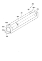
- FIG. 3 is a perspective view showing the standby power supply device body of the first embodiment. Sectional drawing which follows the F9-F9 line of the disaster prevention unit shown in FIG.
- Sectional drawing which follows the F10-F10 line of the disaster prevention unit shown in FIG.
- the side view which shows the refrigerator inclining only the predetermined angle with respect to the horizontal surface in 1st Embodiment.
- the top view which shows the refrigerator main body of 1st Embodiment.
- Sectional drawing which shows the movement of the engaging part of 1st Embodiment.
- the block diagram which shows the structure of the control part of 1st Embodiment.
- the side view which shows the refrigerator of the 1st modification of 1st Embodiment by a partial cross section.
- Sectional drawing which shows the disaster prevention unit of the 1st modification of 1st Embodiment.
- Sectional drawing which shows the disaster prevention unit of the 2nd modification of 1st Embodiment.
- FIG. 24 is a sectional view taken along line F24-F24 of the disaster prevention unit shown in FIG. 23.
- FIG. 24 is a sectional view taken along line F25-F25 of the disaster prevention unit shown in FIG. 23. Sectional drawing which shows the disaster prevention unit of 3rd Embodiment.
- FIG. 27 is a sectional view taken along line F28-F28 of the disaster prevention unit shown in FIG. 26.
- FIG. 32 is a cross-sectional view taken along line F32-F32 of the refrigerator shown in FIG. 31.
- the front view which shows the refrigerator of 6th Embodiment.
- FIG. 36 is a cross-sectional view taken along the line F37-F37 of the refrigerator housing shown in FIG. 35.
- FIG. 38 is a cross-sectional view of the disaster prevention unit accommodating portion shown in FIG. 37 taken along line F38-F38. Sectional drawing which follows the F39-F39 line of the disaster prevention unit accommodation part shown in FIG.
- the side view which shows the refrigerator inclined by the predetermined angle with respect to the horizontal surface in 6th Embodiment.
- the block diagram which shows the structure of the control part of the refrigerator of 6th Embodiment. Sectional drawing which shows the disaster prevention unit accommodating part of 7th Embodiment.
- FIG. 43 is a cross-sectional view of the disaster prevention unit accommodating portion shown in FIG. 42 taken along line F43-F43.
- Sectional drawing which shows the disaster prevention unit accommodating part of the 1st modification of 7th Embodiment.
- Sectional drawing which shows the refrigerator of the 2nd modification of 7th Embodiment.
- Sectional drawing which shows the refrigerator of 8th Embodiment.
- FIG. 48 is a cross-sectional view taken along line F48-F48 of the disaster prevention unit accommodating portion shown in FIG. 47.
- FIG. 50 is a cross-sectional view of the disaster prevention unit accommodating portion shown in FIG. 49 taken along line F50-F50.
- the top view which shows the refrigerator of 10th Embodiment.
- Sectional drawing which shows the refrigerator of 11th Embodiment.
- the refrigerator of the embodiment will be described with reference to the drawings.
- configurations having the same or similar functions are designated by the same reference numerals.
- redundant description of those configurations may be omitted.
- the left and right are defined based on the direction in which the user standing in front of the refrigerator looks at the refrigerator.
- the side closer to the user standing in front of the refrigerator when viewed from the refrigerator is defined as “front” and the far side is defined as “rear”.
- the “lateral width direction” means the left-right direction in the above definition.
- based on XX means “based on at least XX” and includes the case based on another element in addition to XX.
- based on XX is not limited to the case where XX is directly used, but also includes the case where based on the operation and / or processing performed on XX.
- XX is an arbitrary element (for example, arbitrary information).
- FIG. 1 is a diagram illustrating an example of an environment in which the refrigerator 1 according to the first embodiment is installed.
- the refrigerator 1 has, for example, a wireless communication unit 170 and can communicate with the terminal device 2 and the server device 3 via the network NW.
- the network NW may include the Internet, a WAN (Wide Area Network), a home LAN (Local Area Network), and the like. Part or all of the communication in the network NW may be realized wirelessly.
- the refrigerator 1 may directly perform wireless communication with the terminal device 2.
- the terminal device 2 is a terminal device used by the user of the refrigerator 1 and is, for example, a portable terminal device such as a smartphone or a tablet terminal device.
- the terminal device 2 has a display device 2a.
- the display device 2a is a liquid crystal display, an organic EL (Electro Luminescence) display, or the like, and has a display screen (display area) D1 capable of displaying images and / or characters.
- the server device 3 is, for example, a server device managed by a country or a local government.
- the server device 3 transmits disaster information when a disaster such as an earthquake, typhoon, heavy rain, or flood occurs.
- the disaster information includes, for example, an emergency earthquake bulletin transmitted when an earthquake occurs.
- the refrigerator 1 can receive the disaster information transmitted from the server device 3 via the network NW.
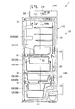
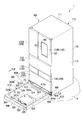
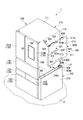
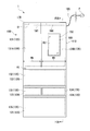
- FIG. 2 is a front view showing the refrigerator 1 of the present embodiment.
- the refrigerator 1 has, for example, a refrigerator body 100 and a disaster prevention unit 200.
- the disaster prevention unit 200 is an example of a "refrigerator attached disaster prevention unit”.
- the refrigerator main body 100 includes, for example, a heat insulating casing 110 (see FIG. 3), a plurality of doors 130, a cooling unit 140 (see FIG. 3), a display device 150, an operation unit 160, a wireless communication unit 170, a power supply circuit unit 180, an acceleration. It has a sensor AS and a control unit 190.
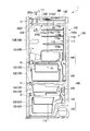
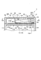
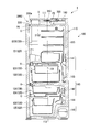
- FIG. 3 is a sectional view taken along line F3-F3 of the refrigerator 1 shown in FIG.
- the heat insulating casing 110 has, for example, an outer box 110a, an inner box 110b, and a heat insulating material 110c filled between the outer box 110a and the inner box 110b, and has heat insulating properties.
- the heat insulating material 110c is, for example, a foamed heat insulating material such as urethane foam.
- the heat insulating casing 110 has a ceiling wall 111, a bottom wall 112, left and right side walls 113 and 114 (see FIG. 4), and a rear wall 115.
- the left and right side walls 113, 114 stand upright from the left and right ends of the bottom wall 112 and are connected to the left and right ends of the ceiling wall 111.
- the rear wall 115 stands upright from the rear end of the bottom wall 112 and is connected to the rear end of the ceiling wall 111.
- a plurality of storage chambers 120 are provided inside the heat insulating casing 110.
- the plurality of storage rooms 120 include, for example, a refrigerating room 121, a vegetable room 122, an ice making room 123 (see FIG. 2), a small freezing room 124, and a main freezing room 125.
- the refrigerating compartment 121 is arranged at the top
- the vegetable compartment 122 is arranged below the refrigerating compartment 121
- the ice making compartment 123 and the small freezing compartment 124 are arranged below the vegetable compartment 122
- the ice making compartment 123 and A main freezer compartment 125 is arranged below the small freezer compartment 124.
- the heat-insulating housing 110 has an opening O on the front side of each storage chamber 120 that allows foodstuffs to be taken in and out of each storage chamber 120.
- the opening O of the storage room 120 is openably and closably closed by a plurality of doors 130.
- the plurality of 130 includes, for example, left and right refrigerating compartment doors 131A and 131B (see FIG. 2) that close the opening O of the refrigerating compartment 121, a vegetable compartment door 132 that closes the opening O of the vegetable compartment 122, and an opening O of the ice making compartment 123.
- the ice making chamber door 133 (see FIG. 2), a small freezing chamber door 134 that closes the opening O of the small freezing chamber 124, and a main freezing chamber door 135 that closes the opening O of the main freezing chamber 125 are included.
- the left and right refrigerating compartment doors 131A and 131B are, for example, double doors.
- the width WB of the right refrigerating compartment door 131B in the lateral width direction is larger than the width WA of the left refrigerating compartment door 131A in the lateral width direction (see FIG. 2). That is, the boundary between the left and right refrigerating compartment doors 131A and 131B is located to the left with respect to the center of the refrigerator main body 100 in the horizontal width direction (the center of the heat insulating casing 110 in the horizontal width direction).
- the vegetable compartment door 132, the ice making compartment door 133, the small freezing compartment door 134, and the main freezing compartment door 135 are drawer-type doors, for example.
- FIG. 4 is a sectional view taken along line F4-F4 of the heat insulating casing 110 shown in FIG.
- the ceiling wall 111 includes, for example, a vacuum heat insulating material (VIP: Vacuum Insulation Panel) 111a.
- the vacuum heat insulating material 111a is formed in a plate shape substantially parallel to the upper surface (or the lower surface) of the ceiling wall 111, and is arranged between the inner box 110b and the heat insulating material 110c.
- VIP Vacuum Insulation Panel
- the ceiling wall 111 may have a reinforcing member 111b.
- the reinforcing member 111b is a member having a rigidity higher than that of at least one of the outer box 110a, the inner box 110b, and the heat insulating material 110c, and is, for example, a metal member.
- the reinforcing member 111b is provided, for example, substantially parallel to the upper surface (or the lower surface) of the ceiling wall 111, and is arranged between the outer box 110a and the heat insulating material 110c.
- the reinforcing member 111b extends over at least part of the left side wall 113 and over at least part of the right side wall 114.
- the left side wall 113 and the right side wall 114 can easily support the load of the disaster prevention unit 200.
- the reinforcing member 111b is not an essential component and may be omitted if sufficient rigidity is ensured.
- the ceiling wall 111 is provided with a terminal portion 117 to which an electric connection member 403 of the disaster prevention unit 200 described later is detachably connected (see FIG. 5).
- the terminal unit 117 includes, for example, a power terminal PT through which a current for supplying power flows and a signal terminal ST through which a signal flows, and can transmit and receive power and a signal.
- the terminal portions 313, 314, 316, 323, 331, 803 of the disaster prevention unit 200 described below also have the power terminal PT and the signal terminal ST, respectively, similarly to the terminal portion 117, and can transmit and receive power and signals. Is.
- the cooling unit 140 includes, for example, a plurality of coolers 141 and 142, a plurality of fans 143 and 144, a compressor 145, and a heat radiation pipe 146 (see FIG. 5).
- the plurality of coolers 141 and 142 are, for example, a cooler 141 for a refrigerating room provided behind the refrigerating room 121 or the vegetable room 122 and a freezing room provided behind the main freezing room 125 or the small freezing room 124. And a cooler 142.
- the plurality of fans 143 include a refrigerating compartment fan 143 for circulating air (cool air) cooled by the refrigerating compartment cooler 141 in the refrigerating compartment 121 and the vegetable compartment 122, and air cooled by the freezing compartment cooler 142 (cooling air). ) Is circulated in the ice making chamber 123, the small freezing chamber 124, and the main freezing chamber 125.
- the compressor 145 is provided, for example, in the machine room at the bottom of the refrigerator 1.
- the compressor 145 compresses the refrigerant gas used for cooling the storage chamber 120.
- the refrigerant gas compressed by the compressor 145 is sent to the refrigerator compartment cooler 141 and the freezer compartment cooler 142 via the heat radiation pipe 146 and the like.
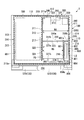
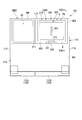
- FIG. 5 is a plan view showing the refrigerator body 100. Note that, in FIG. 5, illustration of a guide member 420 described later and the like is omitted.
- the heat dissipation pipe 146 releases the heat of the refrigerant flowing through the heat dissipation pipe 146 and lowers the temperature of the refrigerant.
- the heat dissipation pipe 146 is provided on the left and right side walls 113 and 114 of the heat insulating casing 110, the rear wall 115, and the like.
- a part of the heat radiating pipe 146 is provided on the ceiling wall 111, and is arranged, for example, at a substantially central portion of the ceiling wall 111. Therefore, a part of the ceiling wall 111 may receive heat from the heat radiation pipe 146 and rise in temperature.
- the display device 150 is provided, for example, on the front surface of the refrigerator compartment door 131B.
- the display device 150 is a liquid crystal display, an organic EL display, or the like, and has a display screen (display area) D2 capable of displaying images and / or characters.
- the operation unit 160 is, for example, a touch panel type input device, and is provided so as to overlap the display screen D2 of the display device 150.
- the user can perform predetermined input and / or selection on the refrigerator main body 100 by operating the operation unit 160.
- the operation unit 160 is not limited to a touch panel type input device, and may be a button or the like provided on the refrigerator main body 100.
- the wireless communication unit 170 includes a high frequency circuit and an antenna, and can be connected to the network NW wirelessly.
- the wireless communication unit 170 is connected to the network NW via an access point provided in the home where the refrigerator 1 is installed.
- the power supply circuit unit 180 is realized by, for example, one or more power supply circuit boards, and is arranged at the upper end of the refrigerator main body 100.
- the power supply circuit unit 180 is electrically connected to the commercial power supply P via the power supply cable 185 of the refrigerator main body 100 and a household outlet. AC power is supplied to the power supply circuit section 180 from the commercial power supply P in a normal time (non-disaster time).
- the commercial power source P is an example of an “external power source”.
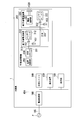
- FIG. 6 is a block diagram showing the connection relationship of the electric power lines of the refrigerator 1.
- the power supply circuit unit 180 converts the AC power supplied from the commercial power supply P into DC power having a voltage suitable for each device included in the refrigerator 1, and supplies the converted DC power to the above devices.
- the power supply circuit unit 180 supplies the DC power obtained by the conversion to the cooling unit 140, the display device 150, the operation unit 160, and the like.
- the acceleration sensor AS is provided on the heat insulating housing 110 or the door 130.
- the acceleration sensor AS detects a large acceleration when an earthquake occurs.
- the detection result of the acceleration sensor AS is output to the control unit 190.
- the acceleration sensor AS is an example of a “sensor”.
- the control unit 190 is realized by, for example, one or more control boards, and is arranged at the upper end of the refrigerator body 100.
- the power supply circuit unit 180 and the control unit 190 may be realized by one board.
- the control unit 190 controls the entire refrigerator 1.
- the control unit 190 comprehensively controls the operations of the cooling unit 140, the display device 150, the operation unit 160, the wireless communication unit 170, the power supply circuit unit 180, and the disaster prevention unit 200.
- the function of the control unit 190 will be described in detail later.
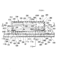
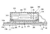
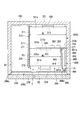
- FIG. 7 is a sectional view taken along line F7-F7 of the disaster prevention unit 200 shown in FIG.
- the disaster prevention unit 200 includes, for example, a case 210, a front cover 220 (see FIG. 10), a standby power supply device 300, a cushioning member 240, a support surface forming member 250, a liquid leak receiving section 260, a standby power supply fixing section 270, and a pair of legs. 280 and a case fixing part 290.
- the case 210 is arranged above the refrigerator main body 100, and is fixed to the refrigerator main body 100 by a case fixing portion 290 described later.
- the case 210 has, for example, an upper wall 211, a bottom wall 212, left and right side walls 213 and 214, and a rear wall 215.
- the top wall 211 and the bottom wall 212 extend substantially parallel to the ceiling wall 111 of the refrigerator body 100.
- the left and right side walls 213 and 214 stand upright from the left and right ends of the bottom wall 212 and are connected to the left and right ends of the upper wall 211.
- the rear wall 215 stands upright from the rear end of the bottom wall 212 and is connected to the rear end of the upper wall 211.
- the case 210 is formed in a box shape having an opening 210a on the front side.
- the center of the case 210 in the width direction substantially coincides with the center of the refrigerator body 100 in the width direction.
- the case 210 is made of synthetic resin, for example, and has electrical insulation. Inside the case 210, an accommodation room (accommodation space) for accommodating devices and / or supplies useful in the event of a disaster is formed.
- a standby power supply chamber (standby power supply space) PS in which the standby power supply device 300 is stored is formed inside the case 210.
- the case 210 has a pair of support portions 401 that support the left and right ends of the standby power supply device 300 housed in the standby power supply chamber PS from below.
- the pair of support portions 401 extend in the depth direction of the refrigerator 1.
- the pair of support portions 401 are separated from each other in the widthwise direction of the refrigerator 1.
- a space is provided between the pair of support portions 401.
- a gap S1 is formed between the standby power supply device 300 and the bottom wall 212 of the case 210 to allow expansion (expansion of battery units 312 and 322 to be described later) of the standby power supply device 300 during aging. There is.
- the front cover 220 is located in front of the opening 210a of the case 210.
- the front cover 220 is pivotally supported by, for example, a hinge (not shown), and closes the opening 210a of the case 210 so as to be openable and closable.
- the front cover 220 is made of a material similar to the door 130 of the refrigerator body 100.
- the front cover 220 is formed of a glass plate when the door 130 of the refrigerator body 100 has a glass plate, and is formed of a metal plate when the door 130 of the refrigerator body 100 has a metal plate. ..
- the sense of unity between the disaster prevention unit 200 and the refrigerator body 100 is enhanced.
- the front cover 220 may be formed of a transparent member.
- the display screen D4 of the standby power supply device 300 which will be described later, can be visually recognized from the outside through the front cover 220.
- at least a part of the front cover 220 may be formed of a transparent or translucent member, and the display area D3 (see FIG. 2) may be formed by a display device provided behind the front cover 220.
- the display area D3 displays characters and / or graphics projected on the front cover 220 from the display device provided behind the front cover 220.
- the standby power supply device 300 is a device that supplies electric power instead of the commercial power supply P in the event of a power failure (when a disaster occurs).
- the standby power supply device 300 is electrically connected to the refrigerator main body 100 via an electric connection member 403 such as a cable or a bus bar.
- the standby power supply device 300 is electrically connected to the commercial power supply P via the electric connection member 403, the power line 404 in the refrigerator body 100 (see FIG. 6), the power cable 185 of the refrigerator body 100, and the like. ..
- the standby power supply device 300 can normally be charged by using a part of the electric power supplied from the commercial power supply P to the refrigerator main body 100.
- the “electric power supplied from the commercial power source P to the refrigerator main body 100” broadly means, for example, the electric power guided from the commercial power source P to the inside of the refrigerator main body 100 via the power cable 185 of the refrigerator main body 100.
- “It can be charged using a part of the electric power supplied from the commercial power supply P to the refrigerator main body 100” means that the electric power supplied from the commercial power supply P to the refrigerator main body 100 is not converted by the refrigerator main body 100 and is a standby power supply.
- the standby power supply device 300 When the standby power supply device 300 can be charged by being supplied to the device 300 (for example, AC power is supplied as it is), the power supplied from the commercial power supply P to the refrigerator body 100 is the desired power in the refrigerator body 100. It includes both the case where the standby power supply device 300 can be charged by being converted into (for example, DC power) and supplied to the standby power supply device 300.
- the standby power supply device 300 may be electrically connected to the commercial power supply P without the power supply circuit unit 180 of the refrigerator main body 100, and may be electrically connected to the commercial power supply P via the power supply circuit unit 180 of the refrigerator main body 100. May be connected physically.
- the electric power is supplied from the commercial power source P via the refrigerator main body 100 to be charged” and “the electric power is supplied from the refrigerator main body 100 to be charged” are the above-mentioned “commercial power source P from the refrigerator main body”. It can be charged with a part of the electric power supplied to 100 ”. That is, these expressions are interchangeable with each other.
- the standby power supply device 300 can be used as a portable power supply separately from the refrigerator main body 100.
- “separately usable from the refrigerator main body 100” and “separable from the refrigerator main body 100” mean that the refrigerator main body 100 can be carried and used at a place different from the installation place.
- the term “portable power source” broadly refers to a portable power source, including a relatively small mobile battery.
- the standby power supply device 300 has, for example, a standby power supply device main body 300U, a main body connector 330, a fan 340, a power supply circuit section 350, a standby power supply overall control section 360, and a storage section 370 (see FIG. 14).
- FIG. 8 is a perspective view showing the standby power supply device main body 300U.
- the standby power supply device main body 300U includes a first standby power supply device 310 and a second backup power supply device 320.
- the first standby power supply device 310 is a backup power supply device that supplies power to the refrigerator main body 100 in the event of a power failure. That is, the first standby power supply device 310 is left integrally with the refrigerator main body 100 (remaining inside the case 210 of the disaster prevention unit 200) at the time of power failure, and the refrigerator 1 such as electric power for driving the compressor 145 and the cooling unit 140. The electric power required to maintain the cooling function of the refrigerator is supplied to the refrigerator main body 100.
- the first standby power supply device 310 includes, for example, the first standby power supply case 311, the battery unit 312, the first terminal portion 313, the second terminal portion 314, the voltage sensor VS1 (see FIG. 6), and the current sensor IS1. (See FIG. 6).
- the first auxiliary power supply case 311 is formed in a box shape, for example.
- the first auxiliary power supply case 311 has a first end 311a and a second end 311b.
- the first end portion 311a is an end portion that faces a main body connector 330 described below.
- the second end 311b is an end located on the side opposite to the first end 311a and facing the second standby power supply device 320.
- the battery unit 312 is housed inside the first standby power supply case 311.
- the battery unit 312 includes one or more secondary batteries.
- the secondary battery is, for example, a lithium ion secondary battery, but may be another type of secondary battery, and the type thereof is not particularly limited.
- the capacity of the battery unit 312 of the first standby power supply device 310 is larger than the capacity of the battery unit 322 of the second standby power supply device 320.
- the capacity of the battery unit 312 of the first standby power supply device 310 is a capacity capable of maintaining the cooling function of the refrigerator main body 100 for several days after a power failure.
- the first terminal portion 313 is provided on the first end portion 311a of the first standby power supply case 311.
- the first terminal portion 313 is a terminal portion for connecting the first standby power supply device 310 and the main body connector 330.
- the first standby power supply device 310 is electrically connected to the refrigerator main body 100 via the main body connector 330, the power supply circuit section 350, and the electric connection member 403 by being connected to the main body connector 330. Accordingly, the battery unit 312 of the first standby power supply device 310 can be charged by being supplied with power from the refrigerator main body 100.
- the second terminal portion 314 is provided on the second end portion 311b of the first standby power supply case 311.
- the second terminal portion 314 is a terminal portion for connecting the first standby power supply device 310 and the second standby power supply device 320.
- the voltage sensor VS1 detects the voltage value of the terminal voltage of the battery unit 312.
- the current sensor IS1 detects the current value of the current charged in the battery unit 312 or discharged from the battery unit 312.
- the detection results of the voltage sensor VS1 and the current sensor IS1 are output to the standby power supply overall control unit 360 via, for example, the first terminal unit 313 and the main body connector 330.
- the second standby power supply device 320 is a standby power supply device that is separated from the refrigerator main body 100 as a portable power supply and can be carried to a desired place and used in the event of a power failure or a disaster requiring evacuation. That is, the second standby power supply device 320 can be used as a standby power supply device when taken out of the case 210 of the disaster prevention unit 200 and carried to a living room, a bedroom, an evacuation center, or the like.
- the second standby power supply device 320 is used, for example, to charge various electronic devices (smartphones, tablet terminals, laptop computers, radios, mobile TVs, etc.) owned by the user.
- the second standby power supply device 320 can supply power to the refrigerator main body 100 together with the first standby power supply device 310 when it is not used separately from the refrigerator main body 100. That is, for example, when it is desired to lengthen the continuous operation time of the refrigerator main body 100 at the time of power failure, the second standby power supply device 320 is left integrally with the refrigerator main body 100 together with the first standby power supply device 310 (the case 210 of the disaster prevention unit 200). The electric power required for maintaining the cooling function of the refrigerator 1 can be supplied to the refrigerator main body 100 together with the first standby power supply device 310.
- the second auxiliary power supply device 320 includes, for example, the second auxiliary power supply case 321, the battery unit 322, the terminal portion 323, the handle 324, the display device 325, the plurality of connectors 326, the power supply circuit portion 327, the voltage sensor VS2 ( 6), a current sensor IS2 (see FIG. 6), and a second standby power supply controller 328.
- the second auxiliary power supply case 321 is formed in a box shape, for example.
- the second auxiliary power supply case 321 has a first end 321a and a second end 321b.
- the first end 321 a is an end facing the first standby power supply device 310.
- the second end 321b is an end located on the side opposite to the first end 321a and arranged toward the front of the refrigerator 1.
- a battery unit 322 is housed inside the second auxiliary power supply case 321.
- the battery unit 322 includes one or more secondary batteries.
- the terminal portion 323 is provided on the first end portion 321a of the second auxiliary power supply case 321.
- the terminal part 323 is a terminal part for connecting the first standby power supply device 310 and the second standby power supply device 320, and is detachably connected to the second terminal part 314 of the first standby power supply device 310.
- the second standby power supply device 320 is connected to the first standby power supply device 310 so that the second standby power supply device 320 is electrically connected to the refrigerator main body 100 via the first standby power supply device 310, the main body connector 330, the power supply circuit unit 350, and the electrical connection member 403. Connected to each other.
- the battery unit 322 of the second standby power supply device 320 can be charged by being supplied with power from the refrigerator body 100.
- the battery unit 322 of the second standby power supply device 320 is electrically connected in parallel to the battery unit 312 of the first standby power supply device 310, for example.
- the battery unit 322 of the second standby power supply device 320 may be electrically connected in series to the battery unit 312 of the first standby power supply device 310.
- the handle 324 is provided on the second end 321b of the second auxiliary power supply case 321.
- the handle 324 is a portion that the user holds when taking out the second auxiliary power supply device 320 from the case 210 of the disaster prevention unit 200 or carrying the second auxiliary power supply device 320.
- the handle 324 is located closest to the opening 210a of the case 210 in the auxiliary power supply unit 300U in a state where the second auxiliary power supply 320 is housed in the case 210 of the disaster prevention unit 200.
- the handle 324 is exposed to the outside of the case 210 through the opening 210a of the case 210 toward the front of the refrigerator 1.
- the display device 325 is provided at the second end 321b of the second auxiliary power supply case 321.
- the display device 325 is a liquid crystal display, an organic EL display, or the like, and has a display screen (display area) D4 capable of displaying images and / or characters.
- the display device 325 may be an LED element or the like that indicates the presence or absence of abnormality and / or the necessity of charging with a color and / or a blinking state.
- the plurality of connectors (power supply units) 326 are provided at the second end 321b of the second auxiliary power supply case 321.
- the plurality of connectors 326 are connection units to which various devices that require electric power are connected. Electric power is supplied to the device connected to the connector 326 from the battery unit 322 of the second standby power supply device 320.
- the plurality of connectors 326 include, for example, a USB (Universal Serial Bus) port, an outlet compatible with various standards, and a cigarette lighter.
- the connector 326 is not limited to the above example, and may be a connector compatible with microUSB or another format.
- the power supply circuit unit 327 of the second backup power supply device 320 is realized by, for example, one or more power supply circuit boards, and is housed inside the second backup power supply case 321.
- the power supply circuit unit 327 converts the electric power output from the battery unit 322 into electric power of a desired voltage and supplies the electric power to each connector 326.
- the power supply circuit unit 327 includes a DC-AC converter when one or more connectors 326 support AC power.
- the voltage sensor VS2 detects the voltage value of the terminal voltage of the battery unit 322.
- the current sensor IS2 detects the current value of the current charged in the battery unit 322 or discharged from the battery unit 322.
- the detection results of the voltage sensor VS2 and the current sensor IS2 are output to the second standby power supply controller 328.
- the detection results of the voltage sensor VS2 and the current sensor IS2 are output to the standby power supply overall control unit 360 via, for example, the terminal units 323, 313, 314 and the main body connector 330.
- the second backup power supply control unit 328 is realized by, for example, one or more control boards, and is housed inside the second backup power supply case 321.
- the power supply circuit unit 327 and the second standby power supply control unit 328 may be realized by one board.
- the second standby power supply controller 328 controls the entire second standby power supply device 320.
- the second standby power control unit 328 controls the operations of the battery unit 322, the display device 325, and the power circuit unit 327.
- the second standby power supply control unit 328 can communicate with the standby power supply overall control unit 360 via the terminal units 323, 313, 314 and the main body connector 330, for example.
- the second standby power control unit 328 can communicate with the control unit 190 of the refrigerator main body 100 via, for example, the terminal units 323, 313, 314, the main body connector 330, and the electrical connection member 403.
- the second standby power supply control unit 328 may be capable of communicating with the standby power supply overall control unit 360 and the control unit 190 of the refrigerator main body 100 by Bluetooth (registered trademark) or another method of wireless communication. ..
- the function of the second standby power supply controller 328 will be described in detail later.
- the widths WA and WB of the left and right refrigerator doors 131A and 131B are different, and the boundary between the left and right refrigerator doors 131A and 131B is located to the left with respect to the center of the refrigerator main body 100 in the lateral width direction. To do.
- the impact applied to the disaster prevention unit 200 when the left and right refrigerator doors 131A and 131B are closed is more likely to be transmitted to the left side region than the right side region in the disaster prevention unit 200. Therefore, in the present embodiment, the power supply circuit unit 327 and the second backup power supply control unit 328 of the second backup power supply device 320 are located in the second backup power supply case 321 on the right side with respect to the center of the second backup power supply case 321. It is arranged unevenly. Accordingly, the impact applied to the disaster prevention unit 200 when the refrigerator doors 131A and 131B are closed is less likely to be transmitted to the power supply circuit unit 327 and the second standby power supply control unit 328.
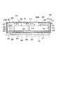
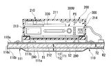
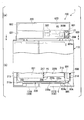
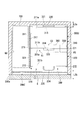
- FIG. 10 is a sectional view taken along line F10-F10 of the disaster prevention unit 200 shown in FIG.
- the second standby power supply device 320 is arranged in front of the first standby power supply device 310 inside the case 210 of the disaster prevention unit 200, and is closer to the opening 210a of the case 210 than the first standby power supply device 310. Located in. The second standby power supply device 320 can be removed from the inside of the case 210 toward the front of the case 210 (that is, toward the front of the refrigerator 1) without interfering with the first standby power supply device 310. The second standby power supply device 320 can be taken out from the inside of the case 210 toward the front of the case 210 while the case 210 of the disaster prevention unit 200 is fixed to the refrigerator body 100.
- the first standby power supply device 310 is larger than the second backup power supply device 320 and heavier than the second backup power supply device 320.
- the first standby power supply device 310 is arranged behind the second backup power supply device 320 inside the case 210 of the disaster prevention unit 200. As a result, the center of gravity of the standby power supply device main body 300U is easily located on the rear side.
- the first standby power supply device 310 and the second standby power supply device 320 are arranged at substantially the same height, and are arranged side by side in the front-rear direction of the refrigerator 1.
- the center of gravity position of the standby power supply device main body 300U can be lowered as compared with the case where one of the first standby power supply device 310 and the second standby power supply device 320 is arranged at a higher position.
- the first backup power supply device 310 is installed inside the case 210 of the disaster prevention unit 200 more than the second backup power supply device 320. It is located below. As a result, the position of the center of gravity of the standby power supply device main body 300U can be lowered.
- the main body connector 330 is provided, for example, at the rear end of the auxiliary power supply chamber PS and faces the auxiliary power supply device main body 300U in the front-rear direction of the refrigerator 1.
- the main body connector 330 has a terminal portion 331 that is detachably connected to the first terminal portion 313 of the first standby power supply device 310.
- the first terminal portion 313 of the first standby power supply device 310 is connected to the terminal portion 331 of the body connector 330 when the first backup power supply device 310 is pushed toward the body connector 330.
- the main body connector 330 is electrically connected to the power supply circuit section 350 of the standby power supply device 300.
- the fan 340 is provided in the standby power supply chamber PS.
- a plurality of intake holes 411 are provided on the left and right side walls 213 and 214 of the case 210.
- the rear wall 215 of the case 210 is provided with a plurality of exhaust holes 412.
- the intake hole 411 and the exhaust hole 412 are ventilation holes that connect the auxiliary power supply chamber PS and the outside of the case 210, respectively.
- the arrangement of the intake holes 411 and the exhaust holes 412 is not limited to the above example, but may be provided in different parts of the case 210.
- the fan 340 sucks the air in the standby power supply chamber PS and exhausts the sucked air to the outside of the case 210 through the exhaust hole 412.
- the air having a relatively low temperature outside the case 210 flows into the auxiliary power supply chamber PS from the intake hole 411.
- the air that has flowed into the standby power supply chamber PS flows around the standby power supply device main body 300U, the power supply circuit unit 350, the standby power supply overall control unit 360, and the like to remove heat from the standby power supply device 300.
- the air whose temperature has risen by removing heat from the standby power supply device 300 is exhausted to the outside of the case 210 by the cooling fan 340. This promotes heat dissipation from the standby power supply device 300.
- the standby power supply device 300 may not have the fan 340. Even when the fan 340 is not provided, the ventilation hole that connects the standby power supply chamber PS and the outside of the case 210 is provided, so that the heat radiation of the standby power supply device 300 can be promoted to some extent.
- the power supply circuit section 350 is realized by, for example, one or more power supply circuit boards, and is arranged at the rear end of the preliminary power supply chamber PS.
- the power supply circuit section 350 is electrically connected to the refrigerator main body 100 via the electric connection member 403. Electric power is supplied to the power supply circuit unit 350 from the refrigerator main body 100.
- the power supply circuit unit 350 converts the electric power supplied from the refrigerator main body 100 into DC power having a voltage suitable for the battery units 312 and 322 of the standby power supply device 300, and supplies the converted DC power to the battery units 312 and 322. As a result, the battery units 312 and 322 are charged.
- the function of the power supply circuit unit 350 may be provided as a part of the power supply circuit unit 180 of the refrigerator body 100. In this case, the power supply circuit section 350 of the standby power supply device 300 may be omitted.
- the standby power supply overall control unit 360 is realized by, for example, one or more control boards, and is arranged at the rear end of the standby power supply chamber PS.
- the power supply circuit section 350 and the standby power supply overall control section 360 may be realized by one board.
- the standby power supply overall control unit 360 controls the entire standby power supply device 300.
- the standby power supply overall control unit 360 controls the operations of the fan 340 and the power supply circuit unit 350.
- the standby power supply overall control unit 360 can communicate with the control unit 190 of the refrigerator main body 100 via the electrical connection member 403.
- the standby power supply overall control unit 360 may be capable of communicating with the control unit 190 of the refrigerator body 100 by Bluetooth or another wireless communication method, instead of the above.
- the function of the standby power supply overall control unit 360 will be described later in detail.
- the power supply circuit unit 350 and the standby power supply overall control unit 360 are arranged in the standby power supply chamber PS in a biased manner to the right of the center of the standby power supply chamber PS. As a result, the impact applied to the disaster prevention unit 200 when the refrigerator doors 131A and 131B are closed is less likely to be transmitted to the power supply circuit section 350 and the standby power supply overall control section 360.
- the storage unit 370 is configured by, for example, an EEPROM (Electrically Erasable Programmable Read-Only Memory) or a ROM (read-only memory). The information stored in the storage unit 370 will be described later in detail.
- EEPROM Electrically Erasable Programmable Read-Only Memory
- ROM read-only memory
- At least one of the center of gravity position G3 of the standby power supply device 300 and the center of gravity position G2 of the disaster prevention unit 200 is provided even when all of the plurality of doors 103 of the refrigerator body 100 are in the fully closed position. Is located behind the center of gravity position G1. With such a configuration, even if the refrigerator 1 shakes due to an earthquake, the stability of the refrigerator 1 is increased and the refrigerator 1 is less likely to tip forward.
- the center position in the front-rear dimension of the standby power supply device 300 (for example, the center position in the front-rear dimension of the standby power supply device main body 300U) C3 is the refrigerator main body 100. Is located rearward of the center position C1 in the front-back direction. Further, the dimensional center position C2 of the disaster prevention unit 200 in the front-rear direction is located rearward of the center position C1 of the refrigerator body 100 in the front-rear direction.
- the distance L3a in the front-rear direction between the rear end of the standby power supply device 300 (for example, the rear end of the standby power supply device main body 300U) and the rear end of the refrigerator main body 100 is equal to that of the standby power supply device 300. It is smaller than the distance L3b in the front-rear direction between the front end (for example, the front end of the auxiliary power supply device main body 300U) and the front end of the refrigerator main body 100.
- the distance L2a in the front-rear direction between the rear end of the disaster prevention unit 200 (for example, the rear end of the case 210) and the rear end of the refrigerator main body 100 is equal to the front end of the disaster prevention unit 200 (for example, the front end of the front cover 220). It is smaller than the distance L2b in the front-rear direction between the front end of the refrigerator body 100.
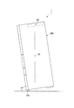
- FIG. 11 is a side view showing the refrigerator 1 tilted forward by a predetermined angle ⁇ (for example, 8 degrees) with respect to the horizontal plane.
- a predetermined angle ⁇ for example, 8 degrees
- At least one of the center of gravity position G3 of the standby power supply device 300 and the center of gravity position G2 of the disaster prevention unit 200 has all of the plurality of doors 130 of the refrigerator main body 100 in the fully open position, and the refrigerator 1 is forward at a predetermined angle ⁇ (
- the refrigerator body 100 is located rearward of the center of gravity G1 of the refrigerator body 100 in a state of being inclined by 8 degrees. According to such a configuration, even if the refrigerator 1 sways relatively greatly due to an earthquake, the refrigerator 1 is less likely to fall forward.
- At least one of the center of gravity position G3 of the standby power supply device 300 and the center of gravity position G2 of the disaster prevention unit 200 has all of the plurality of doors 130 of the refrigerator body 100 in the fully closed position, and the refrigerator 1 is Even when the refrigerator is tilted forward by a predetermined angle ⁇ (for example, 8 degrees), it is located behind the center of gravity G1 of the refrigerator main body 100.
- a predetermined angle ⁇ for example, 8 degrees
- the center of gravity position G3 of the standby power supply device 300 (or the center of gravity position G2 of the disaster prevention unit 200) is the front leg of the refrigerator body 100 even when the refrigerator 1 is tilted forward by a predetermined angle ⁇ (for example, 8 degrees). It is located behind the portion 118. According to such a configuration, the weight of the disaster prevention unit 200 acts in a direction to restore the inclination of the refrigerator 1. This makes it difficult for the refrigerator 1 to fall forward.
- a predetermined angle ⁇ for example, 8 degrees
- the cushioning member 240 and the support surface forming member 250 will be described with reference to FIG. 7.
- a cushioning member 240 and a support surface forming member 250 are provided between the support portion 401 of the case 210 and the standby power supply device 300.
- the buffer member 240 is arranged between the support portion 401 of the case 210 and the standby power supply device main body 300U.
- the cushioning member 240 is formed of an elastic body such as rubber or a spring, and is elastically deformable.
- the standby power supply device main body 300U is supported by the support portion 401 of the case 210 via a cushioning member 240.
- the cushioning member 240 may be provided in the leg portion 280 described later, instead of the above example. That is, a part of the leg portion 280 may be formed by the cushioning member 240.
- the support surface forming member 250 is arranged between the buffer member 240 and the standby power supply device main body 300U.
- the support surface forming member 250 is formed of a member having a smaller friction coefficient than the cushioning member 240.
- the support surface forming member 250 is, for example, a metal plate, and is attached to the entire upper surface of the buffer member 240.
- the auxiliary power supply main body 300U (first and second auxiliary power supply devices 310 and 320) is inserted into the case 210 and the outside of the case 210 by sliding the support surface forming member 250 in a substantially horizontal direction. Ejection is performed. As a result, it is possible to smoothly take out the second standby power supply device 320 when a disaster occurs and to remove the first standby power supply device 310 when replacing due to aged deterioration.
- the liquid leak receiving section 260 is provided below the standby power supply device 300.
- the liquid leak receiving section 260 is arranged, for example, in the standby power source accommodating chamber PS below the standby power source device main body 300U.
- the liquid leakage receiver 260 receives and stores the liquid when the battery units 312 and 322 are damaged due to an earthquake or the like and the liquid leaks.
- the liquid leakage receiving section 260 is provided between the pair of supporting sections 401 of the case 210 supporting the standby power supply device 300.
- the liquid leak receiver 260 is, for example, an oil pan, but is not limited to this.
- the liquid leak receiving portion 260 may be a rib 265 (see FIG. 10) that is provided at the front end portion of the case 210 and prevents the leaked liquid from flowing out of the case 210 through the opening 210a of the case 210. ..
- the standby power supply fixing unit 270 is provided to fix the standby power supply device 300.
- the standby power supply fixing part 270 includes, for example, a pair of first power supply fixing parts 271 fixing the first standby power supply device 310 and a pair of second power supply fixing parts 272 fixing the second backup power supply device 320.
- the pair of first power supply fixing portions 271 are movable along the width direction of the refrigerator 1 in a direction toward each other and a direction away from each other.
- the pair of first power supply fixing portions 271 are moved in directions toward each other after the first standby power supply device 310 is housed in the case 210.
- the first standby power supply device 310 is sandwiched between the first power supply fixing portion 271 and the main body connector 330, and the position of the first backup power supply device 310 is fixed.
- the pair of first power supply fixing portions 271 are moved in directions away from each other by operating a release button (not shown). As a result, the first standby power supply device 310 can be removed.
- the pair of second power supply fixing portions 272 are movable along the width direction of the refrigerator 1 in a direction toward each other and a direction away from each other. After the second standby power supply device 320 is housed in the case 210, the pair of second power supply fixing portions 272 are moved in a direction in which they approach each other. As a result, the second backup power supply device 320 is sandwiched between the second power supply fixing portion 272 and the first backup power supply device 310, and the position of the second backup power supply device 320 is fixed. The pair of second power supply fixing portions 272 are moved in directions away from each other by operating a release button (not shown). As a result, the second standby power supply device 320 can be removed.
- the pair of legs 280 are provided, for example, on the lower surface of the bottom wall 212 of the case 210 of the disaster prevention unit 200, and extend in the front-rear direction of the case 210.
- the legs 280 are placed on the ceiling wall 111 of the refrigerator body 100.
- a gap S2 is formed between the bottom wall 212 of the case 210 of the disaster prevention unit 200 and the ceiling wall 111 of the refrigerator body 100.
- FIG. 12 is a plan view showing the refrigerator main body 100 of this embodiment.
- the ceiling wall 111 of the refrigerator main body 100 has a guide member 420 provided on the upper surface of the ceiling wall 111.
- the guide member 420 guides the leg portion 280 of the disaster prevention unit 200 toward the rear end portion of the ceiling wall 111.
- the guide member 420 includes, for example, a pair of upright portions 421 that are upright so as to sandwich the leg portions 280 of the disaster prevention unit 200.
- the leg portion 280 of the disaster prevention unit 200 is guided by the pair of upright portions 421, and thus is guided toward the rear end portion of the ceiling wall 111 without shifting the position of the refrigerator 1 in the widthwise direction.
- the refrigerator main body 100 and the disaster prevention unit 200 are carried into the installation place in the home while being separated from each other. Then, the disaster prevention unit 200 is installed in the refrigerator body 100 after the refrigerator body 100 is installed in the installation place in the home.
- the installation of the disaster prevention unit 200 on the refrigerator body 100 starts by placing the legs 280 of the disaster prevention unit 200 on the front end portion of the ceiling wall 111 of the refrigerator body 100 that was previously installed. Then, the leg portion 280 of the disaster prevention unit 200 is slid along the upper surface of the ceiling wall 111 of the refrigerator main body 100 while being guided by the guide member 420. Thereby, even if the weight of the disaster prevention unit 200 is relatively heavy, the refrigerator 1 including the disaster prevention unit 200 can be installed relatively easily.
- the case fixing portion 290 has a pair of first case fixing portions 291 and a pair of second case fixing portions 292.
- the pair of first case fixing portions 291 are provided, for example, at the front end portion of the case 210.
- the first case fixing portion 291 has a first portion 291a fixed to the case 210 and a second portion 291b along the ceiling wall 111 of the refrigerator body 100.
- the second portion 291b has a screw insertion hole 293 (see FIG. 7).
- the screw insertion hole 293 faces the screw hole 294 provided in the ceiling wall 111 of the refrigerator main body 100 (for example, the screw hole 294 provided in the reinforcing member 111b).
- the front end portion of the case 210 is fixed to the ceiling wall 111 of the refrigerator main body 100 by the fastening member (bolt or screw or the like) 295 passed through the screw insertion hole 293 engaging with the screw hole 294.
- the pair of second case fixing portions 292 are provided at the rear end of the case 210, for example.
- the second case fixing portion 292 has a first portion 292a fixed to the case 210 and a second portion 292b along the ceiling wall 111 of the refrigerator body 100.
- the second portion 292b has an engagement hole 296.
- the ceiling wall 111 has an engaging portion 297 that is detachably engaged with the engaging hole 296.
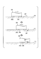
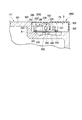
- FIG. 13 is a sectional view showing the movement of the engaging portion 297.
- the engaging portion 297 has, for example, an inclined portion whose height increases from the front end portion toward the rear end portion.
- the rear end of the engaging portion 297 extends in a substantially vertical direction.
- the engaging portion 297 is provided so as to be vertically swingable with respect to the upper surface of the ceiling wall 111, and should be sunk toward the inside of the ceiling wall 111 when the disaster prevention unit 200 rides on the engaging portion 297. Allows the disaster prevention unit 200 to pass.
- the engaging portion 297 engages with the engaging hole 296, the disaster prevention unit 200 is supported by the rear end portion of the engaging portion 297 and cannot move forward. As a result, the rear end of the disaster prevention unit 200 is fixed.
- the engagement portion 297 is moved downward by operating a release button (not shown). Thereby, the disaster prevention unit 200 can be removed from the ceiling wall 111 of the refrigerator main body 100.
- control unit 190 of the refrigerator main body 100 the standby power supply overall control unit 360 of the disaster prevention unit 200, and the second standby power supply control unit 328 of the disaster prevention unit 200 will be described.
- control unit 190 of the refrigerator main body 100, the standby power supply overall control unit 360, and the second standby power supply control unit 328 are collectively referred to as the control unit 500 of the refrigerator 1.
- FIG. 14 is a block diagram showing the configuration of the control unit 500 of the refrigerator 1.
- a hardware processor such as a CPU (Central Processing Unit) or GPU (Graphics Processing Unit). It is realized by.
- some or all of these functional units are implemented by hardware (including the circuit unit; circuitry) such as ASIC (Application Specific Integrated Circuit), PLD (Programmable Logic Device), FPGA (Field Programmable Gate Array). It may be realized, or may be realized by the cooperation of software and hardware.
- the control unit 190 of the refrigerator body 100 includes, for example, a disaster detection unit 511, a cooling unit control unit 512, a charge / discharge control unit 513, an information acquisition unit 514, an information generation unit 515, and a display control unit 516.
- a disaster detection unit 511 a cooling unit control unit 512, a charge / discharge control unit 513, an information acquisition unit 514, an information generation unit 515, and a display control unit 516.
- some of these functional units may be provided as part of the standby power supply overall control unit 360 or the second standby power supply control unit 328 instead of the refrigerator main body 100.
- the disaster detection unit 511 detects the occurrence of a disaster (for example, an earthquake) based on at least one of the disaster information received via the network NW and the detection result of the acceleration sensor AS. When the occurrence of a disaster is detected, the disaster detection unit 511 transmits a predetermined signal indicating the occurrence of a disaster to the standby power supply overall control unit 360 and the second standby power supply control unit 328. Further, the disaster detection unit 511 detects that the occurrence of a disaster (for example, heavy rain) is imminent based on the disaster information received via the network NW, and when it is detected that the occurrence of a disaster is imminent, The predetermined signal is transmitted to the standby power supply overall control unit 360 and the second standby power supply control unit 328.
- occurrence of a disaster for example, an earthquake
- the cooling unit controller 512 controls driving of the refrigerating compartment fan 143, the freezing compartment fan 144, the compressor 145, and the like. For example, when the disaster detection unit 511 detects the occurrence of a disaster, the cooling unit control unit 512 shifts to a low power mode in which the power consumption of the cooling unit 140 is suppressed.
- the charging / discharging control unit 513 maintains the battery units 312 and 322 of the standby power supply device 300 in a charged state by using the electric power supplied from the commercial power supply P to the refrigerator main body 100 in a normal time (non-disaster time). On the other hand, the charging / discharging control unit 513 discharges at least the battery unit 312 of the first standby power supply device 310 at the time of power failure, and drives the cooling unit 140 using the electric power obtained by discharging the battery unit 312.
- the charging / discharging control unit 513 receives a user's operation indicating an instruction to supply power from the battery unit 322 of the second standby power supply device 320 to the refrigerator main body 100 through the operation unit 160 of the refrigerator main body 100 or the terminal device 2.
- the battery unit 322 of the second standby power supply device 320 is also discharged, and the cooling unit 140 is driven using the electric power obtained by discharging.
- the charging / discharging control unit 513 of the first standby power supply device 310 when the second standby power supply device 320 is used as a portable power source and the remaining capacity is reduced and then electrically connected to the first standby power supply device 310, the charging / discharging control unit 513 of the first standby power supply device 310.
- the battery unit 322 of the second standby power supply device 320 may be charged using the electric power discharged from the battery unit 312.
- the information acquisition unit 514 provides information indicating the presence / absence of abnormality of the standby power supply device 300, the deterioration state of the battery units 312 and 322 of the standby power supply device 300, and the remaining capacity of the battery units 312 and 322 of the standby power supply device 300 to the standby power supply. It is acquired from the overall control unit 360.
- the information acquisition unit 514 normally acquires the above information from the standby power supply overall control unit 360 at a predetermined cycle (for example, once a month).
- the information acquisition unit 514 reserves information indicating the presence or absence of an abnormality in the standby power supply device 300 and the remaining capacity of the battery units 312 and 322 of the standby power supply device 300. It is acquired from the power supply overall control unit 360.
- the information generation unit 515 based on the information acquired by the information acquisition unit 514, the display screen D2 of the display device 150 of the refrigerator main body 100, the display screen D1 of the display device 2a of the terminal device 2, the display device 325 of the standby power supply device 300.
- the information generation unit 515 includes information indicating whether or not there is an abnormality in the standby power supply devices 310 and 320, information regarding the deterioration states of the battery units 312 and 322 of the standby power supply devices 310 and 320, and the batteries of the standby power supply devices 310 and 320. At least one of the information regarding the remaining capacities of the units 312 and 322 is generated as information to be displayed in the display area D.
- the “information regarding the deterioration state of the battery units 312 and 322” includes, for example, the reference time for replacing the battery units 312 and 322 of the standby power supply devices 310 and 320 and the necessity of replacing the battery units 312 and 322. It includes information indicating at least one.
- the “information on the remaining capacity of the battery units 312 and 322” is, for example, the operation continuable time of the refrigerator main body 100 when the refrigerator main body 100 is operated by the power supplied from the first standby power supply device 310 (how long, Whether the operation can be continued) and information indicating the number of times charging is possible when the terminal device 2 or another terminal device is charged by the power supplied from the second standby power supply device 320. ..
- the “information regarding the remaining capacity of the battery units 312 and 322” is the information of the refrigerator main body 100 when the refrigerator main body 100 is operated by the power supplied from both the first standby power supply device 310 and the second standby power supply device 320. It may also include information indicating the continuous operation time.
- the information generation unit 515 has information about the presence / absence of abnormality of the standby power supply units 310 and 320, information indicating the deterioration state of the battery units 312 and 322 of the standby power supply units 310 and 320, and the standby power supply unit 310 in the above-described predetermined cycle. , 320 indicating the remaining capacities of the battery units 312, 322 are generated as information to be displayed in the display area D.
- the disaster detection unit 511 detects the occurrence of a disaster
- the information generation unit 515 determines whether there is an abnormality in the standby power supply devices 310 and 320, and the remaining battery units 312 and 322 of the standby power supply devices 310 and 320.
- Information indicating the capacity is generated as information to be displayed in the display area D.
- the display control unit 516 displays the information on the display device 150 of the refrigerator main body 100, the display device 2a of the terminal device 2, and the second standby power supply device 320.
- the information is transmitted to the display device 325 and the display device provided behind the front cover 220 of the disaster prevention unit 200, and the information is displayed in the display area D.
- the standby power supply overall control unit 360 includes, for example, an abnormality detection unit 521, a deterioration detection unit 522, and a remaining capacity detection unit 523. However, some of these functional units may be provided as part of the control unit 190 of the refrigerator main body 100 or the second standby power supply control unit 328 instead of the standby power supply device 300.
- the abnormality detection unit 521 performs, for example, test discharge of the battery units 312 and 322 of the standby power supply devices 310 and 320, and based on the detection results of the voltage sensors VS1 and VS2 and the current sensors IS1 and IS2, the standby power supply devices 310 and 320. Detect the presence or absence of abnormality. The detection result of the abnormality detection unit 521 is transmitted to the control unit 190 and the second standby power supply control unit 328 of the refrigerator main body 100.
- the deterioration detecting unit 522 detects the battery units 312 and 322 based on the detection results of the voltage sensors VS1 and VS2 and the current sensors IS1 and IS2 when the battery units 312 and 322 of the standby power supply devices 310 and 320 are subjected to the test discharge. Detect the deterioration state.
- the storage unit 370 of the standby power supply device 300 information indicating the deterioration characteristics of the battery units 312 and 322 (for example, the relationship between the combination of the integrated value of the discharge amount and the voltage drop amount of the terminal voltage and the deterioration degree). Is remembered.
- the deterioration detecting unit 522 detects the integrated value of the discharge amount from the battery units 312 and 322 detected in the test discharge, the voltage drop amount of the terminal voltage of the battery units 312 and 322, and the deterioration characteristic stored in the storage unit 370. And the information indicating that the deterioration state of the battery units 312 and 322 is detected.
- the method of detecting the deterioration state is not limited to the above example, and various known methods can be used.
- the detection result of the deterioration detection unit 522 is transmitted to the control unit 190 and the second standby power supply control unit 328 of the refrigerator main body 100.
- the remaining capacity detection unit 523 detects the remaining capacity of the battery units 312 and 322 based on the detection result of the terminal voltages of the battery units 312 and 322 of the standby power supply devices 310 and 320 detected by the voltage sensors VS1 and VS2.
- the method of detecting the remaining capacity is not limited to the above example, and various known methods can be used.
- the detection result of the remaining capacity detection unit 523 is transmitted to the control unit 190 and the second standby power supply control unit 328 of the refrigerator main body 100.
- the abnormality detection unit 521, the deterioration detection unit 522, and the remaining capacity detection unit 523 normally perform the test discharge of the battery units 312 and 322 at the above-described predetermined cycle to determine whether or not there is an abnormality in the battery units 312 and 322 and / or The deterioration state and the remaining capacities of the battery units 312 and 322 are detected.
- the abnormality detection unit 521 and the remaining capacity detection unit 523 receive a predetermined signal indicating the occurrence of a disaster from the disaster detection unit 511 of the refrigerator main body 100, for example, a change in the terminal voltage of the battery units 312, 322.
- the presence or absence of an abnormality in the battery units 312 and 322 and the remaining capacity of the battery units 312 and 322 are detected based on the presence or absence of the battery, and the detection results are transmitted to the control unit 190 and the second standby power supply control unit 328 of the refrigerator body 100. ..
- the abnormality detection unit 521 receives a predetermined signal indicating the occurrence of an earthquake from the disaster detection unit 511 of the refrigerator main body 100
- the battery is detected after the occurrence of the earthquake (after the detection result by the acceleration sensor AS falls within the threshold).
- the detection result is transmitted to the control unit 190 and the second standby power supply control unit 328 of the refrigerator main body 100.
- the second standby power supply control unit 328 includes, for example, a discharge control unit 531, a remaining capacity detection unit 532, an information generation unit 533, and a display control unit 534. However, some of these functional units may be provided as a part of the control unit 190 of the refrigerator main body 100 or the entire standby power supply control unit 360 instead of the second standby power supply device 320.
- the discharge control unit 531 discharges and discharges the battery unit 322 of the second standby power supply device 320 when the second standby power supply device 320 is used as a portable power supply and a device to be supplied with power is connected to the connector 326. The electric power obtained by this is supplied to the device.
- the remaining capacity detection unit 532 based on the detection result of the terminal voltage of the battery unit 322 of the second standby power supply 320 detected by the voltage sensor VS2, for example, when the second standby power supply 320 is used as a portable power supply, The remaining capacity of the battery unit 322 is detected.
- the method of detecting the remaining capacity is not limited to the above example, and various known methods can be used.
- the information generation unit 533 outputs information to be displayed on the display screen D4 of the second standby power supply device 320 based on the detection result of the remaining capacity detection unit 532 when the second standby power supply device 320 is used as a portable power supply, for example. To generate.
- the display control unit 534 transmits the information to the display device 325 and displays the information on the display screen D4. Further, when the display control unit 534 receives the information to be displayed on the display screen D4 from the control unit 190 of the refrigerator main body 100 or the standby power supply overall control unit 360, the display control unit 534 transmits the information to the display device 325, and the information is displayed on the display screen. Display on D4.
- the case 210 of the disaster prevention unit 200 arranged above the refrigerator body 100 is arranged, and the standby power supply device 300 is housed inside the case 210.
- electricity can be secured when a disaster occurs by utilizing the space above the refrigerator main body 100, which easily becomes a dead space.
- the standby power supply device 300 has a first standby power supply device 310 that supplies power to the refrigerator body 100 in the event of a power failure. With such a configuration, even if a power failure occurs, the operation of the refrigerator main body 100 can be continued, and it becomes easy to secure food for several days until the recovery proceeds. Further, in this embodiment, the standby power supply device 300 includes a second standby power supply device 320 that can be used as a portable power supply. With such a configuration, the second standby power supply device 320 can be used at a desired place in a home, an evacuation center, or the like.
- the second standby power supply device 320 is connected to the first standby power supply device 310, so that electric power is supplied from the refrigerator main body 100 via the first standby power supply device 310 and can be charged. With such a configuration, it becomes easier to dispose the second standby power supply device 320 in front of the first standby power supply device 310 as compared with the case where the main connector 330 is provided with the electrical connection portion for the second standby power supply device 320. .. When the second standby power supply device 320 is arranged in front of the first standby power supply device 310, the ease of taking out the second backup power supply device 320 is improved.
- the first standby power supply device 310 is heavier than the second standby power supply device 320, and is arranged behind the second backup power supply device 320 or below the second backup power supply device 320. With such a configuration, the center of gravity of the disaster prevention unit 200 is likely to be rearward or downward, and the refrigerator 1 including the disaster prevention unit 200 is easily stabilized.
- FIG. 15 is a side view which shows the refrigerator 1 of a 1st modification with a partial cross section.
- the refrigerator 1 is often arranged along the wall W of the house.
- a fan (not shown) for promoting heat radiation of the compressor 145 is provided in the machine room at the bottom of the refrigerator body 100.
- the air blown by the fan rises in the gap between the rear wall 115 and the wall W of the refrigerator main body 100 by the chimney effect. That is, the air blown by the fan rises along the rear wall 115 of the refrigerator body 100.
- FIG. 16 is a sectional view showing a disaster prevention unit 200 of this modification.
- the plurality of intake holes 411 are provided in the rear wall 215 of the case 210.
- the plurality of exhaust holes 412 are provided in the left and right side walls 213 and 214 of the case 210.
- the disaster prevention unit 200 is provided, for example, on the rear wall 215 of the case 210, and guides at least a part of the air that has risen along the rear wall 115 of the refrigerator main body 100 toward the intake hole 411 of the case 210. It has a guide member 601.
- the guide member 601 is provided, for example, slightly above the intake hole 411.
- the guide member 601 projects rearward of the case 210 and is located above the gap between the rear wall 115 and the wall W of the refrigerator body 100.
- the air that has risen along the rear wall 115 of the refrigerator main body 100 hits the guide member 601 and changes its flow direction, is guided to the intake hole 411, and is guided from the intake hole 411 to the standby power supply chamber PS.
- the fan 340 may be provided or may be omitted.
- the guide member 601 by providing the guide member 601, at least a part of the air that has risen due to the chimney effect along the rear wall 115 of the refrigerator body 100 can be efficiently taken into the inside of the case 210. .. Thereby, the heat dissipation of the standby power supply device 300 can be improved.
- the fan 340 is driven to take in air from the intake hole 411, so that the air in the gap between the rear wall 115 and the wall W of the refrigerator main body 100 is cased. It is possible to positively guide the inside of 210. If the air in the gap between the rear wall 115 and the wall W of the refrigerator main body 100 can be positively guided to the inside of the case 210, the air will be generated in the gap between the rear wall 115 and the wall W of the refrigerator main body 100. It becomes hard to stay, and heat dissipation of the heat dissipation pipe 146 provided on the rear wall 115 of the refrigerator main body 100 can be promoted. Thereby, the heat dissipation of the refrigerator main body 100 can be improved.
- FIG. 17 is sectional drawing which shows the disaster prevention unit 200 of a 2nd modification.
- the outer surface of the rear wall 115 of the case 210 of the disaster prevention unit 200 is embossed. That is, the outer surface of the rear wall 115 of the case 210 has a plurality of concave portions 605 and a plurality of convex portions 606.
- the concave portions 605 and the convex portions 606 are alternately arranged in the vertical direction.
- FIG. 18 is sectional drawing which shows the refrigerator 1 of a 3rd modification.
- the ceiling wall 111 of the refrigerator main body 100 has a first region R1 and a second region R2.
- the first region R1 is located below the backup power supply device 300 (below the backup power supply chamber PS).
- the second region R2 is located outside the first region R1. That is, the second region R2 does not overlap the standby power supply device 300 in the vertical direction.
- the thickness T1 of the heat insulating material 110c of at least a part of the first region R1 of the ceiling wall 111 is thinner than the thickness T2 of the heat insulating material 110c of the second region R2 of the ceiling wall 111.
- the heat insulating material 110c is thin in the region between the pair of legs 280 of the disaster prevention unit 200 in the first region R1.
- the vacuum heat insulating material 111a is not provided at least in the region where the heat insulating material 110c is thin.
- the upper surface of the ceiling wall 111 of the refrigerator main body 100 is easily cooled by the cold air in the storage chamber 120, and the temperature of the upper surface of the ceiling wall 111 does not easily rise. Therefore, the temperature of the air in the gap S2 between the ceiling wall 111 of the refrigerator body 100 and the disaster prevention unit 200 is unlikely to rise. As a result, the heat dissipation of the standby power supply device 300 can be improved.
- FIG. 19 is sectional drawing which shows the refrigerator 1 of a 4th modification.
- the thickness T1 of at least a part of the heat insulating material 110c in the first region R1 of the ceiling wall 111 (when the heat insulating material 110c exists so as to sandwich the vacuum heat insulating material 111a in the vertical direction
- the total thickness t1 of the heat insulating material 110c on the upper side and the heat insulating material 110c on the lower side of the vacuum heat insulating material 111a is greater than the thickness T2 of the heat insulating material 110c in the second region R2 of the ceiling wall 111.
- the heat insulating material 110c is thicker in a region larger than the region between the pair of legs 280 of the disaster prevention unit 200 in the widthwise direction of the refrigerator 1.
- FIG. 20 is sectional drawing which shows the refrigerator 1 of a 5th modification.
- the bottom wall 212 of the case 210 of the disaster prevention unit 200 has a heat insulating property.
- the case 210 has a heat insulating wall (bottom wall 212) between the standby power supply chamber PS and the refrigerator main body 100.
- the bottom wall 212 has, for example, a first portion 212a made of synthetic resin and a second portion 212b formed of a heat insulating member, and the first portion 212a and the second portion 212b are vertically arranged. overlapping.
- the second portion 212b is formed of, for example, a vacuum heat insulating material.
- the second portion 212b may be formed of a foamed heat insulating material such as urethane foam.
- FIG. 21 is sectional drawing which shows the refrigerator 1 of the 6th modification.
- the bottom wall 212 of the case 210 of the disaster prevention unit 200 has a pair of inclined surfaces 611 and 612. Each of the inclined surfaces 611 and 612 is located upward as it goes to the outer peripheral side of the case 210.
- the bottom wall 212 of the case 210 includes a flat surface 613 located at the center of the bottom wall 212, a left inclined surface 611 adjacent to the left side of the flat surface 613, and a right inclined surface 612 adjacent to the right side of the flat surface 613. Have.
- the sum of the width W1 in the lateral width direction of the left inclined surface 611 and the width W2 in the lateral width direction of the right inclined surface 612 is substantially the same as or larger than the width W3 of the flat surface 613 in the lateral width direction.
- the present embodiment is different from the first embodiment in that the disaster prevention unit 200 has disaster prevention article storage chambers GS1, GS2, GS3 capable of containing the disaster prevention article 700.
- the configuration other than that described below is similar to that of the first embodiment.
- FIG. 22 is a front view showing the refrigerator 1 according to the second embodiment.
- the disaster prevention unit 200 has a case 210 that is larger than that in the first embodiment.
- the center of the case 210 in the width direction substantially coincides with the center of the refrigerator body 100 in the width direction.
- the case 210 has four accommodation chambers.
- FIG. 23 is a cross-sectional view showing the disaster prevention unit 200 of this embodiment.
- the case 210 has first to third disaster prevention article accommodating chambers (disaster prevention article accommodating spaces) GS1, GS2, GS3 in addition to the auxiliary power source accommodating room PS in which the auxiliary power supply device 300 is accommodated.
- the four storage chambers including the disaster prevention article storage chambers GS1, GS2, GS3 and the standby power supply storage chamber PS are partitioned from each other by a partition wall 217 provided inside the case 210.
- the partition wall 217 is made of synthetic resin and has electrical insulation.
- FIG. 24 is a sectional view taken along line F24-F24 of the disaster prevention unit 200 shown in FIG.
- FIG. 25 is a sectional view taken along line F25-F25 of the disaster prevention unit 200 shown in FIG.
- the first to third disaster prevention article storage chambers GS1, GS2, GS3 have, for example, substantially the same depth as the standby power supply storage chamber PS in the front-rear direction of the refrigerator body 100.
- Disaster prevention supplies (disaster prevention goods) 700 are stored in each of the disaster prevention supplies storage rooms GS1, GS2, GS3.
- the disaster prevention article 700 is, for example, a plastic bottle of drinking water, long-term storable food (dry bread, canned food, retort food, instant food, candy, chocolate, etc.), plastic tank for water supply, cassette stove / cylinder, portable radio, helmet, disaster prevention. Examples include, but are not limited to, riding hoods, thick gloves, flashlights, all-purpose knives, masks, tissue paper, wet tissues, toilets, first aid kits, medicines, handheld warmers, lighter matches, and candles. Some or all of these are stored in the emergency supplies storage rooms GS1, GS2, GS3 in a state of being put in an emergency bag.
- the first and second disaster prevention article storage chambers GS1 and GS2 are arranged on the left side of the standby power supply storage chamber PS.
- the first disaster prevention article storage room GS1 and the standby power supply storage room PS are arranged at substantially the same height position.
- the second disaster prevention article storage room GS2 is arranged above the first disaster prevention article storage room GS1 and at a position higher than the standby power supply storage room PS.
- the third disaster prevention article storage room GS3 is arranged above the standby power supply storage room PS.
- the second disaster prevention article storage room GS2 and the third disaster prevention article storage room GS3 are arranged at the same height.
- the standby power source storage chamber PS is located at the lowest position among the four storage chambers including the first to third disaster prevention article storage chambers GS1, GS2, GS3 and the standby power source storage chamber PS.
- the weight of the standby power supply device 300 is heavier than the weight of the disaster prevention article 700. Therefore, when the standby power supply chamber PS is provided below, the center of gravity of the disaster prevention unit 200 is lowered, and the disaster prevention unit 200 is easily stabilized.
- the standby power supply chamber PS has the refrigerating compartment door 131A on the right side with respect to the center of the case 210 in the widthwise direction (right and left with respect to the center of the refrigerator body 100 in the widthwise direction).
- 131B are arranged so as to be biased on the side opposite to the side on which the boundary is biased.
- the entire standby power supply chamber PS has a position where the left and right refrigerating compartment doors 131A and 131B do not overlap with the left and right refrigerating compartment doors 131A and 131B in the front-rear direction. Are arranged on the right side.
- the refrigerator 1 of the third embodiment will be described.
- the present embodiment is different from the second embodiment in that the disaster prevention unit 200 has a lighting device housing chamber LS capable of housing the lighting device 800.
- the configuration other than that described below is similar to that of the second embodiment.
- FIG. 26 is a sectional view showing the disaster prevention unit 200 according to the third embodiment.
- the case 210 includes, in addition to the standby power source storage chamber PS and the first to third disaster prevention article storage chambers GS1, GS2, GS3, a lighting device storage chamber (a lighting device storage chamber) in which the lighting device 800 is stored. Space) LS.
- the lighting device accommodating chamber LS is arranged on the right side of the standby power source accommodating chamber PS.
- the lighting device accommodation chamber LS and the standby power source accommodation chamber PS are arranged at substantially the same height position.
- the lighting device accommodation room LS is arranged below the third disaster prevention article accommodation room GS3.
- the auxiliary power supply device 300 in the lateral direction of the case 210 is arranged. It is easy to place it near the center. Thereby, the stability of the refrigerator 1 including the disaster prevention unit 200 in the lateral width direction can be enhanced.
- the disaster prevention article storage room GS3 and the lighting device storage room LS are partitioned from each other by a partition wall 217 provided inside the case 210.
- a partition wall 218 that is attachable to and detachable from the case 210 is provided between the standby power source storage chamber PS and the lighting device storage chamber LS.
- the partition wall 218 is made of synthetic resin and has electrical insulation. If the partition wall 218 is provided between the standby power supply accommodation room PS and the lighting equipment accommodation room LS, even if the standby power supply equipment 300 is damaged by an earthquake, for example, the interior of the illumination equipment accommodation room LS The electrical safety of is more reliably ensured.
- the partition wall 218 can be removed from the case 210, even if the first auxiliary power supply device 310 is larger than the second auxiliary power supply device 320, the first auxiliary power supply device 310 can be taken out in front of the case 210. ..
- the lighting device 800 can be used as a portable light separately from the refrigerator body 100 (can be used separately from the case 210 of the disaster prevention unit 200). That is, the lighting device 800 can be carried and used in a place different from the place where the refrigerator body 100 is installed.
- FIG. 27 is a perspective view showing a lighting device 800 of this embodiment.
- the lighting device 800 includes, for example, a lighting device case 801, a battery 802 (see FIG. 28), a terminal portion 803, a first light portion 804, a second light portion 805, a handle 806, and a control portion 807.
- the lighting device case 801 is formed in a long and thin box shape, for example.
- the lighting device case 801 has a first end 801a and a second end 801b.
- the first end 801a is an end facing the first standby power supply device 310 (see FIG. 28).
- the second end portion 801b is an end portion that is located on the opposite side of the first end portion 801a and that is arranged toward the front of the refrigerator 1.
- the battery 802 is housed inside the lighting device case 801.
- the terminal portion 803 is provided on the first end portion 801a of the lighting device case 801.
- the terminal portion 803 is, for example, a terminal portion for connecting the lighting device 800 and the first standby power supply device 310, and is detachably connected to a third terminal portion 316 of the first standby power supply device 310 described later.
- the lighting device 800 is electrically connected to the refrigerator main body 100 through the first auxiliary power supply device 310, the main body connector 330, the power supply circuit unit 350, and the electric connection member 403 by being connected to the first auxiliary power supply device 310. To be done.
- the battery 802 of the lighting device 800 can be charged by being supplied with power from the refrigerator body 100.
- the battery 802 of the lighting device 800 is supplied with power from the power supply circuit section 350 and can be charged.
- the first light unit 804 is provided, for example, at the second end 801b of the lighting device case 801.
- the first light unit 804 is a light unit that functions as an emergency light.
- the first light unit 804 has a hemispherical lens 804a that is provided on the end surface of the second end 801b of the lighting device case 801, and that protrudes forward.
- the first light unit 804 has a hemispherical lens 804a, and thus emits light radially toward the front and the periphery of the first light unit 804.
- part of the light emitted from the first light portion 804 is rearward (first end portion) from the end surface of the second end portion 801b of the lighting device case 801, because the lens 804a is formed in a hemispherical shape. Head toward 801a).
- the second light portion 805 is provided, for example, between the first end portion 801a and the second end portion 801b in the lighting device case 801.
- the second light unit 805 is a light larger than the first light unit 804.
- the second light unit 805 is turned on when, for example, the lighting device 800 is used as a portable light and a light amount larger than that of the first light unit 804 is required.
- the handle 806 is provided on the second end 801b of the lighting device case 801.
- the handle 806 is a portion that the user holds when taking out the lighting device 800 from the case 210 of the disaster prevention unit 200 and when carrying the lighting device 800.
- the handle 806 is located closest to the opening 210a of the case 210 in the lighting device 800 when the lighting device 800 is housed in the case 210 of the disaster prevention unit 200.
- the handle 806 is exposed to the outside of the case 210 through the opening 210a of the case 210 toward the front of the case 210.
- the control unit 807 is realized by, for example, one or more control boards.
- the control unit 807 controls the lighting of the first light unit 804 and the second light unit 805.
- the disaster detection unit 511 of the refrigerator main body 100 detects the occurrence of the disaster based on at least one of the disaster information received via the network NW and the detection result of the acceleration sensor AS, the occurrence of the disaster is detected.
- the predetermined signal shown is also transmitted to the control unit 807 of the lighting device 800.
- the control unit 807 of the illumination device 800 receives the predetermined signal, the control unit 807 turns on the first light unit 804 for a certain period of time until the release operation is performed.
- the width W4 of the first standby power supply device 310 in the widthwise direction is larger than the width W5 of the second backup power supply device 320 in the widthwise direction.
- the first standby power supply device 310 has a first region 310a and a second region 310b.
- the first region 310a faces the second standby power supply device 320 in the front-back direction of the refrigerator 1.
- the first region 310a has a second terminal portion 314 connected to the second standby power supply device 320.
- the second region 310b faces the lighting device 800 in the front-back direction of the refrigerator 1.
- the second region 310b has a third terminal portion 316 connected to the lighting device 800.
- the first light unit 804 of the lighting device 800 is located in front of the front end portion of the standby power supply device 300 (for example, the second end 321b of the second standby power supply device 320). Accordingly, the first light unit 804 can illuminate the handle 324 and / or the display screen D4, the connector 326, and the like of the second standby power supply device 320.
- the first light unit 804 is located in front of the front end portion of the partition wall 218 located between the lighting device accommodation chamber LS and the standby power source accommodation chamber PS. Accordingly, the first light unit 804 can illuminate the handle 324, the display screen D4, the connector 326, and the like of the second auxiliary power supply device 320 without being obstructed by the partition wall 218.
- the first light portion 804 is located in front of the front end portion of the partition wall 217 located between the disaster prevention article storage chambers GS1, GS2, GS3 and the standby power supply storage chamber PS. Thereby, the 1st light part 804 can illuminate the front end part of the 1st-3rd disaster prevention article storage room GS1, GS2, GS3, without being interrupted by the partition wall 217.
- the charging / discharging control unit 513 of the refrigerator main body 100 when the charging / discharging control unit 513 of the refrigerator main body 100 is electrically connected to the first standby power supply device 310 after the lighting device 800 is used as a portable light and the remaining capacity of the battery 802 is reduced,
- the battery 802 of the lighting device 800 may be charged using electric power discharged from the battery unit 312 of the first standby power supply device 310.
- the space above the refrigerator main body 100 which tends to become a dead space, can be used to secure electricity, food, and lighting when a disaster occurs.
- the configuration of the lighting device 800 is not limited to the above example.
- the lighting device 800 may include only one of the first light unit 804 and the second light unit 805.
- the lighting device 800 is not limited to a lighting device that can be used as a portable light, and may be a lighting device fixed to the case 210 of the disaster prevention unit 200.
- FIG. 29 is a figure which shows the refrigerator 1 of a 1st modification.
- 29B is a cross-sectional view taken along line bb in FIG. 29A.
- the front cover 220 is formed of a translucent member.
- the “translucent member” may be transparent, semitransparent, or colored.
- the front cover 220 is formed as a light guide plate. That is, the front cover 220 includes the first surface 220a facing forward, the second surface 220b located on the opposite side of the first surface 220a, and the light located between the first surface 220a and the second surface 220b. It has a transmission part 220c.
- the second surface 220b is provided with unevenness for diffusing light.
- the front cover 220 of the disaster prevention unit 200 has a cutout portion C that avoids the lighting device 800.
- the front end of the lighting device 800 projects to the outside of the case 210.
- the first light portion 804 of the lighting device 800 is arranged in the cutout portion C of the front cover 220, is located below a part of the front cover 220, and is located beside a part of the front cover 220.
- the illumination device 800 allows light to enter the light transmitting portion 220c of the front cover 220 from below or from the side of the front cover 220.
- the light incident on the light transmitting portion 220c of the front cover 220 travels inside the front cover 220 and is diffused by the second surface 220b. As a result, the entire front cover 220 becomes bright. With such a configuration, the position of the disaster prevention unit 200 can be more easily understood when a power failure occurs.
- FIG. 30 is sectional drawing which shows the disaster prevention unit 200 of a 2nd modification.
- the front end of the upper wall 211 of the case 210 is located rearward of the front end of the bottom wall 212 of the case 210.
- the front cover 220 is disposed so as to be inclined toward the vertical direction so as to be positioned rearward as it advances upward. With such a configuration, it is possible to reduce the feeling of pressure when the refrigerator 1 is viewed from the front.
- the present embodiment is different from the first embodiment in that the standby power supply device 300 is arranged between the main freezer compartment 125 and the floor surface F.
- the configuration other than that described below is similar to that of the first embodiment.
- FIG. 31 is a perspective view showing the refrigerator 1 according to the fourth embodiment.
- the heat insulating casing 110 of the refrigerator main body 100 is provided between the lowest storage chamber (for example, the main freezing chamber 125) among the plurality of storage chambers 120 and the floor surface F on which the refrigerator 1 is installed.
- It has a disaster prevention unit accommodation section 900.
- the disaster prevention unit accommodating section 900 has, for example, a standby power supply accommodating room PS in which the auxiliary power supply device 300 is accommodated and a lighting device accommodating room LS in which the lighting device 800 is accommodated.
- the heat-insulating housing 110 has a heat-insulating partition wall 910 between the lowermost storage room (for example, the main freezing room 125) and the disaster prevention unit housing 900 (standby power supply housing PS, lighting device housing LS). (See FIG. 32).
- the partition wall 910 includes a heat insulating material 110c.
- the partition wall 910 may include a vacuum heat insulating material.
- the standby power supply device 300 is formed in a flat shape substantially parallel to the floor surface F on which the refrigerator 1 is installed.
- each of the first standby power supply device 310 and the second standby power supply device 320 is formed in a flat shape substantially parallel to the floor surface F.
- the first standby power supply device 310 and the second standby power supply device 320 are formed to have substantially the same thickness.
- the backup power supply device 300 (first and second backup power supply devices 310 and 320) is housed in the backup power supply storage chamber PS, and is located between the bottom storage room (for example, the main freezer compartment 125) and the floor surface F. To position.
- the standby power supply device 300 can be taken out toward the front of the refrigerator 1 from between the floor surface F and the storage room at the lowest stage (for example, the main freezing room 125).
- the first standby power supply device 310 is a standby power supply device that remains in the refrigerator main body 100 in the event of a power failure and supplies electric power to the refrigerator main body 100.
- the first standby power supply device 310 is removed from the refrigerator main body 100 at the time of replacement due to deterioration over time.
- the second standby power supply device 320 is a standby power supply device that is separated from the refrigerator main body 100 as a portable power supply at the time of power failure and can be carried to a desired place and used.
- the second standby power supply device 320 is located in front of at least a part of the first standby power supply device 310, and can be taken out toward the front of the refrigerator 1 without interfering with the first backup power supply device 310.
- the first standby power supply device 310 can be taken out from the standby power supply chamber PS toward the front of the refrigerator 1.
- the first standby power supply device 310 has a first portion 921 and a second portion 922.
- the first portion 921 is located behind the second standby power supply device 320.
- the second portion 922 does not overlap the second standby power supply device 320 in the front-back direction of the refrigerator 1.
- the front end portion of the second portion 922 is arranged at substantially the same position as the front end portion of the second auxiliary power supply device 320 in the front-back direction of the refrigerator 1.
- the second portion 922 has, for example, a handle 930.
- the handle 930 is a part that the user holds when taking out the first standby power supply device 310 from the refrigerator main body 100. With such a configuration, the first standby power supply device 310 can be easily removed from the refrigerator main body 100 at the time of replacement due to deterioration over time.
- the refrigerator 1 further includes a makeup cover 940 that is detachably attached to the refrigerator body 100.
- the makeup cover 940 is arranged in front of the standby power supply device 300 and the lighting device 800, and covers the backup power supply device 300 and the lighting device 800 from the outside of the refrigerator 1.
- the standby power supply device 300 and the lighting device 800 are exposed to the outside of the refrigerator 1 toward the front of the refrigerator 1.
- the handles 324 and 930 of the standby power supply device 300 and the handles 806 of the lighting device 800 are exposed to the outside of the refrigerator 1 toward the front of the refrigerator 1 when the makeup cover 940 is removed from the refrigerator body 100. To do.
- FIG. 32 is a sectional view taken along line F32-F32 of the refrigerator 1 according to the fourth embodiment.
- the disaster prevention unit accommodating portion 900 includes, for example, the support portion 401, the cushioning member 240, and the support surface forming member 250.
- the support portion 401 supports the standby power supply device 300 from below.
- the buffer member 240 is located between the support 401 and the standby power supply device 300.
- the support surface forming member 250 is located between the buffer member 240 and the standby power supply device 300.
- the buffer member 240 and / or the support surface forming member 250 may be omitted.
- the heavy standby power supply device 300 is arranged at the bottom of the refrigerator main body 100. This can improve the stability of the refrigerator 1 against an earthquake or the like. Further, when the standby power supply device 300 is arranged at the lowermost part of the refrigerator main body 100, it becomes easier to remove the standby power supply device 300 from the refrigerator 1 as compared with the case where the standby power supply device 300 is arranged above the refrigerator main body 100. As a result, it is possible to more smoothly remove the first standby power supply device 310 at the time of replacement due to deterioration over time and the removal of the second standby power supply device 320 at the time of occurrence of a disaster.
- the refrigerator 1 of the fifth embodiment will be described.
- This embodiment is different from the fourth embodiment in that the disaster prevention unit 200 is arranged on the side of the refrigerator body 100.
- the configuration other than that described below is similar to that of the fourth embodiment.
- FIG. 33 is a perspective view showing the refrigerator 1 according to the fifth embodiment.
- the case 210 of the disaster prevention unit 200 is arranged on the side of the refrigerator body 100 (on the right side in the drawing, it may be on the left side).
- the case 210, the standby power supply device 300, and the lighting device 800 are vertically arranged along the right side wall 114 (or the left side wall 113) of the refrigerator main body 100.
- the opening 210a of the case 210 is formed.
- the standby power supply device 300 and the lighting device 800 are detached upward from the case 210.
- the heavy power supply unit 300 is not arranged at a high position in the refrigerator main body 100. This can improve the stability of the refrigerator 1 against an earthquake or the like. Further, when the standby power supply device 300 is arranged on the side of the refrigerator main body 100, it becomes easier to remove the standby power supply device 300 from the refrigerator 1 as compared with the case where the standby power supply device 300 is arranged above the refrigerator main body 100. As a result, it is possible to more smoothly remove the first standby power supply device 310 at the time of replacement due to deterioration over time and the removal of the second standby power supply device 320 at the time of occurrence of a disaster.
- FIG. 34 is a front view showing the refrigerator 1 of the present embodiment.
- the refrigerator 1 has, for example, a refrigerator main body 100 and a disaster prevention unit housing portion 200Z (see FIG. 35).
- the disaster prevention unit accommodation section 200Z is an example of a “accommodation section”.
- the refrigerator main body 100 includes, for example, a heat insulating casing 110 (see FIG. 35), a plurality of doors 130, a cooling unit 140 (see FIG. 35), a display device 150, an operation unit 160, a wireless communication unit 170, a power supply circuit unit 180, an acceleration. It has a sensor AS and a control unit 190.
- the control unit 190 centrally controls the operations of the cooling unit 140, the display device 150, the operation unit 160, the wireless communication unit 170, the power supply circuit unit 180, and the disaster prevention unit accommodation unit 200Z.
- FIG. 35 is a sectional view taken along line F35-F35 of the refrigerator 1 shown in FIG.
- a duct 116 for guiding the cool air that has passed through the refrigerating compartment cooler 141 and is cooled is provided inside the refrigerating compartment 121.
- the duct 116 extends in a substantially vertical direction along the rear wall 115 of the heat insulating casing 110, and forms a flow path between the duct 116 and the rear wall 115, through which the cool air cooled by the refrigerator compartment cooler 141 flows. is doing.
- the duct 116 has a plurality of cold air outlets 116a for supplying the cool air flowing through the flow path to a plurality of height regions in the refrigerating chamber 121.
- the cool air flowing through the flow path is blown into the refrigerating chamber 121 from the cool air outlet 116a.
- the plurality of cold air outlets 116a are arranged in the refrigerating chamber 121 at a plurality of heights.
- FIG. 36 is a block diagram showing the connection relationship of the power lines of the refrigerator 1.
- the power supply circuit unit 180 converts the AC power supplied from the commercial power supply P into DC power having a voltage suitable for each device included in the refrigerator 1, and supplies the converted DC power to the above devices.
- the power supply circuit unit 180 supplies the DC power obtained by the conversion to the cooling unit 140, the display device 150, the operation unit 160, and the like.
- the disaster prevention unit accommodating portion 200Z is provided inside the heat insulating casing 110.
- the disaster prevention unit accommodating portion 200Z is provided at the uppermost portion inside the heat insulating casing 110. That is, the disaster prevention unit accommodating portion 200Z is provided between the uppermost storage chamber (for example, the refrigerating chamber 121) among the plurality of storage chambers 120 and the ceiling wall 111 of the heat insulating casing 110.
- the disaster prevention unit accommodation part 200Z of the present embodiment is an example of a "first accommodation part".
- an accommodation room (accommodation space) S for accommodating devices and / or supplies useful in the event of a disaster is formed inside the disaster prevention unit accommodation section 200Z.
- the disaster prevention unit accommodation section 200Z defines the accommodation room S.
- the accommodation chamber S is a space in which the cold air outlet 116a does not exist and cold air is not supplied.
- the cold air is not supplied means that the cold air is not positively (intentionally) supplied, such as a gap between the opening 200a of the disaster prevention unit accommodating portion 200Z and the front cover 220 described later. Includes the case where unintentional cold air flows in through.
- the disaster prevention unit accommodating portion 200Z has a configuration in which the accommodation chamber S of the disaster prevention unit accommodating portion 200Z is at least partially partitioned (eg, partitioned from the storage chamber 120) inside the heat insulating casing 110.
- the disaster prevention unit accommodating portion 200Z has, for example, a partition wall 210Z and a front cover 220 as a configuration for partitioning the accommodation chamber S of the disaster prevention unit accommodating portion 200Z inside the heat insulating casing 110.
- the disaster prevention unit accommodating portion 200Z has an opening 200a that opens toward the front of the refrigerator 1.
- the accommodation room S is exposed to the outside of the disaster prevention unit accommodation section 200Z through the opening 200a.
- the user can put an item in and out of the accommodation chamber S through the opening 200a.
- the opening 200a is located behind the upper ends of the refrigerating compartment doors 131A and 131B and faces the refrigerating compartment doors 131A and 131B.
- the front cover 220 is located in front of the opening 200a of the disaster prevention unit accommodation section 200Z.
- the front cover 220 is pivotally supported by, for example, a hinge hg (see FIG. 39) and closes the opening 200a of the disaster prevention unit accommodating portion 200Z so as to be openable and closable.
- the front cover 220 may be formed of, for example, a transparent member.
- the display screen D4 of the standby power supply device 300 which will be described later, becomes visible through the front cover 220.
- at least a part of the front cover 220 may be formed of a transparent or translucent member, and the display area D3 may be formed by the display device BD provided behind the front cover 220 (see FIG. 39). ..
- the display area D3 may be formed by the display device BD provided behind the front cover 220 (see FIG. 39). ..
- characters and / or graphics projected on the front cover 220 from the display device BD provided behind the front cover 220 are displayed.
- the partition wall 210Z is provided inside the heat insulating casing 110.
- the partition wall 210Z is provided between the uppermost storage chamber (for example, the refrigerating chamber 121) of the plurality of storage chambers 120 and the storage chamber S of the disaster prevention unit storage portion 200Z.
- the partition wall 210Z is provided above the uppermost cold air outlet 116a among the plurality of cold air outlets 116a, and the uppermost cold air outlet 116a and the ceiling wall of the heat insulating casing 110 are provided. It is arranged at a height position between 111.
- the partition wall 210Z extends in a substantially horizontal direction in the width direction of the refrigerator 1 and the front-rear direction of the refrigerator 1.
- the partition wall 210Z is provided over substantially the entire width of the heat insulating casing 110 in the widthwise direction of the refrigerator 1, and is connected to the left side wall 113 and the right side wall 114, respectively.
- the storage chamber S of the disaster prevention unit storing portion 200Z is partitioned between the uppermost storage chamber 120 (for example, the refrigerating chamber 121) and the ceiling wall 111 of the heat insulating casing 110. ing.
- the partition wall 210Z forms the bottom wall of the disaster prevention unit accommodation section 200Z.
- the partition wall 210Z may be provided integrally with the heat insulating casing 110, or may be provided separately from the heat insulating casing 110.
- the partition wall 210Z is provided integrally with the heat insulating casing 110.
- the partition wall 210Z has, for example, an inner box upper part 210aZ, an inner box lower part 210bZ, and a heat insulating material 210cZ filled between the inner box upper part 210aZ and the inner box lower part 210bZ, and has a heat insulating property.
- the heat insulating material 210cZ is, for example, a foamed heat insulating material such as urethane foam.
- the thickness of the partition wall 210Z (for example, the minimum thickness) is thicker than the thickness of the ceiling wall 111 of the heat insulating casing 110 (for example, the minimum thickness).
- the thickness (for example, the minimum thickness) of the heat insulating material 210cZ of the partition wall 210Z is thicker than the thickness (for example, the minimum thickness) of the heat insulating material 110c of the ceiling wall 111 of the heat insulating casing 110.
- FIG. 37 is a sectional view taken along line F37-F37 of the refrigerator 1 shown in FIG.
- the partition wall 210Z includes, for example, a vacuum heat insulating material (VIP: Vacuum Insulation Panel) 211a.
- the vacuum heat insulating material 211a is formed in a plate shape substantially parallel to the lower surface of the partition wall 210Z, and is arranged between the inner box lower portion 210bZ and the heat insulating material 210cZ.
- the vacuum heat insulating material 211a is provided, the cold air that circulates in the storage chamber 120 is hard to be warmed by the temperature of the disaster prevention unit accommodating portion 200Z.
- the vacuum heat insulating material 211a when the vacuum heat insulating material 211a is provided, it is possible to prevent the heat of the standby power supply device 300 from being transmitted to the cold air in the storage chamber 120 when the backup power supply device 300 of the disaster prevention unit accommodation section 200Z described later generates heat. it can.
- all or part of the partition wall 210Z does not necessarily have the heat insulating property, and may be formed of a material having no heat insulating property.
- the partition wall 210Z may have a reinforcing member 211b.
- the reinforcing member 211b is, for example, a member having higher rigidity than one or more of the inner box upper part 210aZ, the inner box lower part 210bZ, and the heat insulating material 210cZ, and is, for example, a metal member.
- the reinforcing member 211b is provided, for example, substantially parallel to the upper surface of the partition wall 210Z, and is arranged between the inner box upper portion 210aZ and the heat insulating material 210cZ.
- the reinforcing member 211b extends over at least a part of the left side wall 113 and over at least a part of the right side wall 114.
- the left side wall 113 and the right side wall 114 can easily support the load of the disaster prevention unit housing section 200Z.
- the reinforcing member 211b is not an essential component and may be omitted if sufficient rigidity is ensured.
- the storage room S includes a standby power supply storage room (standby power supply storage space) PS in which the standby power supply device 300 is stored, and a disaster prevention article storage room (disaster control article storage space) GS in which the disaster prevention supplies 700 are stored.
- a partition wall 217 is provided between the standby power source storage room PS and the disaster prevention article storage room GS.
- the standby power source storage room PS and the disaster prevention article storage room GS are separated from each other by a partition wall 217.
- the partition wall 217 is made of, for example, a synthetic resin and has electrical insulation.
- the standby power supply chamber PS is provided with a standby power supply device 300, a buffer member 240, a support surface forming member 250, a liquid leakage receiving portion 260, and a backup power source fixing portion 270.
- the standby power supply device 300 is a device that supplies electric power instead of the commercial power supply P in the event of a power failure (when a disaster occurs).
- the standby power supply device 300 is electrically connected to the refrigerator main body 100 via a power line 404 (see FIG. 36) in the refrigerator main body 100.
- the standby power supply device 300 is electrically connected to the commercial power supply P via the power line 404 in the refrigerator body 100, the power cable 185 of the refrigerator body 100, and the like (see FIG. 36).
- the standby power supply device 300 can be used as a portable power supply separately from the refrigerator main body 100.
- "separately usable from the refrigerator main body 100" and “separable from the refrigerator main body 100” can be used by being separated from the heat insulating casing 110 and carried to a place different from the place where the refrigerator main body 100 is installed.
- the term “portable power source” broadly refers to a portable power source, including a relatively small mobile battery.
- the standby power supply device main body 300U of the standby power supply device 300 includes the first standby power supply device 310 and the second backup power supply device 320.
- the first standby power supply device 310 is left integrally with the refrigerator main body 100 at the time of a power failure (remains in the storage chamber S of the disaster prevention unit storage portion 200Z), and the power for driving the compressor 145 and the cooling unit 140 is supplied to the refrigerator 1. Electric power necessary for maintaining the cooling function is supplied to the refrigerator main body 100.
- the first standby power supply device 310 includes, for example, a first standby power supply case 311, a battery unit 312, a first terminal portion 313, a second terminal portion 314, a voltage sensor VS1 (see FIG. 36), and a current sensor IS1 (see FIG. 36). ) Has.
- the first terminal portion 313 is provided on the first end portion 311a of the first standby power supply case 311.
- the first terminal portion 313 is a terminal portion for connecting the first standby power supply device 310 and the main body connector 330.
- the first standby power supply device 310 is electrically connected to the refrigerator main body 100 via the main body connector 330 and the power supply circuit section 350 by being connected to the main body connector 330. Accordingly, the battery unit 312 of the first standby power supply device 310 can be charged by being supplied with power from the refrigerator main body 100.
- the second terminal portion 314 is provided on the second end portion 311b of the first standby power supply case 311.
- the second terminal portion 314 is a terminal portion for connecting the first standby power supply device 310 and the second standby power supply device 320.
- the terminal portion 314 includes, for example, a power terminal PT through which a current for supplying power flows and a signal terminal ST through which a signal flows, and can transmit and receive power and a signal.
- the first terminal 313 described above and the terminal portions 316, 323, 331, 803 described below also have a power terminal PT and a signal terminal ST, respectively, similarly to the terminal portion 117, and can transmit and receive power and signals. ..
- the second standby power supply device 320 is a standby power supply device that is separated from the refrigerator main body 100 as a portable power supply and can be carried to a desired place and used in the event of a power failure or a disaster requiring evacuation. That is, the second standby power supply device 320 can be used as a standby power supply device in a state where it is taken out of the storage room S of the disaster prevention unit storage portion 200Z and carried to a living room, a bedroom, an evacuation center, or the like.
- the second standby power supply device 320 is used, for example, to charge various electronic devices (smartphones, tablet terminals, laptop computers, radios, mobile TVs, etc.) owned by the user.
- the second standby power supply device 320 can supply power to the refrigerator main body 100 together with the first standby power supply device 310 when it is not used separately from the refrigerator main body 100. That is, for example, when it is desired to lengthen the continuous operation time of the refrigerator main body 100 at the time of power failure, the second standby power supply device 320 is left integrally with the refrigerator main body 100 together with the first standby power supply device 310 (for the disaster prevention unit accommodating portion 200Z). By being left in the accommodation room S), the electric power necessary for maintaining the cooling function of the refrigerator 1 can be supplied to the refrigerator main body 100 together with the first standby power supply device 310.
- the second auxiliary power supply device 320 includes, for example, the second auxiliary power supply case 321, the battery unit 322, the terminal portion 323, the handle 324, the display device 325, the plurality of connectors 326, the power supply circuit portion 327, the voltage sensor VS2 ( 36), a current sensor IS2 (see FIG. 36), and a second standby power supply controller 328.
- the terminal portion 323 is provided on the first end portion 321a of the second auxiliary power supply case 321.
- the terminal part 323 is a terminal part for connecting the first standby power supply device 310 and the second standby power supply device 320, and is detachably connected to the second terminal part 314 of the first standby power supply device 310.
- the second standby power supply device 320 is electrically connected to the refrigerator main body 100 via the first standby power supply device 310, the main body connector 330, and the power supply circuit unit 350 by being connected to the first standby power supply device 310. ..
- the battery unit 322 of the second standby power supply device 320 can be charged by being supplied with power from the refrigerator body 100.
- the battery unit 322 of the second standby power supply device 320 is electrically connected in parallel to the battery unit 312 of the first standby power supply device 310, for example.
- the battery unit 322 of the second standby power supply device 320 may be electrically connected in series to the battery unit 312 of the first standby power supply device 310.
- the handle 324 is provided on the second end 321b of the second auxiliary power supply case 321.
- the handle 324 is a portion that the user holds when taking out the second auxiliary power supply device 320 from the inside of the accommodation room S of the disaster prevention unit accommodation portion 200Z and when carrying the second auxiliary power supply device 320.
- the handle 324 is positioned closest to the opening 200a of the disaster prevention unit accommodating portion 200Z in the auxiliary power supply main body 300U when the second auxiliary power supply device 320 is accommodated in the accommodation chamber S of the disaster prevention unit accommodating portion 200Z. To do.
- the handle 324 is exposed to the outside of the disaster prevention unit accommodation part 200Z through the opening 200a of the disaster prevention unit accommodation part 200Z toward the front of the refrigerator 1.
- the second standby power supply control unit 328 can communicate with the standby power supply overall control unit 360 via the terminal units 323, 313, 314 and the main body connector 330, for example. Further, the second standby power supply control unit 328 can communicate with the control unit 190 of the refrigerator main body 100 via the terminal units 323, 313, 314 and the main body connector 330, for example. However, instead of the above, the second standby power supply control unit 328 may be capable of communicating with the standby power supply overall control unit 360 and the control unit 190 of the refrigerator main body 100 by Bluetooth (registered trademark) or another method of wireless communication. ..
- the widths WA and WB of the left and right refrigerator doors 131A and 131B are different, and the boundary between the left and right refrigerator doors 131A and 131B is located to the left with respect to the center of the refrigerator main body 100 in the lateral width direction. To do.
- the impact applied to the disaster prevention unit housing part 200Z when the left and right refrigerator doors 131A and 131B are closed is more likely to be transmitted to the left side region than the right side region in the disaster prevention unit housing part 200Z.
- the power supply circuit unit 327 and the second backup power supply control unit 328 of the second backup power supply device 320 are located in the second backup power supply case 321 on the right side with respect to the center of the second backup power supply case 321. It is arranged unevenly. As a result, the impact applied to the disaster prevention unit housing section 200Z when the refrigerator doors 131A and 131B are closed is less likely to be transmitted to the power supply circuit section 327 and the second standby power supply control section 328.
- FIG. 38 is a sectional view taken along line F38-F38 of the disaster prevention unit housing portion 200Z shown in FIG. 39 is a cross-sectional view taken along line F39-F39 of the disaster prevention unit accommodating portion 200Z shown in FIG.
- the second standby power supply device 320 is arranged in front of the first standby power supply device 310 inside the storage chamber S of the disaster prevention unit storage portion 200Z, and compared with the first backup power supply device 310, the disaster prevention unit storage portion. It is located near the opening 200a of 200Z.
- the second standby power supply device 320 is removable from the inside of the storage chamber S toward the front of the storage chamber S (that is, toward the front of the refrigerator 1) without interfering with the first standby power supply device 310.
- the first standby power supply device 310 is larger than the second backup power supply device 320 and heavier than the second backup power supply device 320.
- the first standby power supply device 310 is arranged behind the second backup power supply device 320 inside the storage chamber S of the disaster prevention unit storage portion 200Z. As a result, the center of gravity of the standby power supply device main body 300U is easily located on the rear side.
- the first standby power supply device 310 and the second standby power supply device 320 are arranged at substantially the same height, and are arranged side by side in the front-rear direction of the refrigerator 1. As a result, the center of gravity position of the standby power supply device main body 300U can be lowered as compared with the case where one of the first standby power supply device 310 and the second standby power supply device 320 is arranged at a higher position.
- the first standby power supply device 310 and the second standby power supply device 320 are arranged vertically, the first standby power supply device 310 is the second backup power supply device inside the storage chamber S of the disaster prevention unit storage portion 200Z. It is arranged below 320. As a result, the position of the center of gravity of the standby power supply device main body 300U can be lowered.
- the standby power supply overall control unit 360 is realized by, for example, one or more control boards and is arranged in the standby power supply chamber PS.
- the power supply circuit section 350 and the standby power supply overall control section 360 may be realized by one board.
- the standby power supply overall control unit 360 controls the entire standby power supply device 300.
- the standby power supply overall control unit 360 controls the operation of the power supply circuit unit 350.
- the standby power supply overall control unit 360 can communicate with the control unit 190 via a communication line provided between the standby power supply overall control unit 360 and the control unit 190 of the refrigerator body 100, for example.
- the overall standby power supply control unit 360 may be capable of communicating with the control unit 190 of the refrigerator main body 100 by Bluetooth or another type of wireless communication. The function of the standby power supply overall control unit 360 will be described later in detail.
- the power supply circuit section 350 and the standby power supply overall control section 360 are arranged in the accommodation room S with a bias toward the right side with respect to the center of the accommodation room S. As a result, the impact applied to the disaster prevention unit housing section 200Z when the refrigerator doors 131A and 131B are closed is less likely to be transmitted to the power supply circuit section 350 and the standby power supply overall control section 360.
- the center of gravity G3 of the standby power supply device 300 is located behind the center of gravity G1 of the refrigerator main body 100 in a state where all of the plurality of doors 130 of the refrigerator main body 100 are in the fully open position. With such a configuration, even if the refrigerator 1 shakes due to an earthquake, the refrigerator 1 provided with the disaster prevention unit housing portion 200Z is unlikely to fall forward.
- the center of gravity position G3 of the standby power supply device 300 is located behind the center of gravity position G1 of the refrigerator main body 100 even when all of the plurality of doors 103 of the refrigerator main body 100 are in the fully closed position.
- the center position in the front-rear dimension of the standby power supply device 300 (for example, the center position in the front-rear direction of the standby power supply device main body 300U) C3 is the refrigerator main body 100. Is located rearward of the center position C1 in the front-back direction. From another perspective, the distance L3a in the front-rear direction between the rear end of the standby power supply device 300 (for example, the rear end of the standby power supply device main body 300U) and the rear end of the refrigerator main body 100 is equal to that of the standby power supply device 300. It is smaller than the distance L3b in the front-rear direction between the front end (for example, the front end of the auxiliary power supply device main body 300U) and the front end of the refrigerator main body 100.
- FIG. 40 is a side view showing the refrigerator 1 tilted forward by a predetermined angle ⁇ (eg, 8 degrees) with respect to the horizontal plane.
- the center of gravity G3 of the standby power supply device 300 is in a state where all of the plurality of doors 130 of the refrigerator main body 100 are in the fully open position and the refrigerator 1 is tilted forward by a predetermined angle ⁇ (for example, 8 degrees). Is located behind the center of gravity position G1. According to such a configuration, even if the refrigerator 1 sways relatively greatly due to an earthquake, the refrigerator 1 is less likely to fall forward.
- the refrigerator 1 in the center of gravity position G3 of the standby power supply device 300, all of the plurality of doors 130 of the refrigerator body 100 are in the fully closed position, and the refrigerator 1 is tilted forward by a predetermined angle ⁇ (for example, 8 degrees). Even in the state, it is located behind the center of gravity G1 of the refrigerator body 100. With such a configuration, the stability of the refrigerator 1 is increased and the refrigerator 1 is less likely to fall forward.
- a predetermined angle ⁇ for example, 8 degrees
- the center of gravity position G3 of the standby power supply device 300 is located behind the front leg portion 118 of the refrigerator main body 100 even when the refrigerator 1 is tilted forward by a predetermined angle ⁇ (for example, 8 degrees).
- a predetermined angle ⁇ for example, 8 degrees.
- the cushioning member 240 and the support surface forming member 250 will be described with reference to FIG.
- a buffer member 240 and a support surface forming member 250 are provided between the partition wall 210Z of the disaster prevention unit accommodating portion 200Z and the standby power supply device 300.
- the buffer member 240 is arranged between the partition wall 210Z of the disaster prevention unit accommodation section 200Z and the standby power supply device main body 300U.
- the cushioning member 240 is formed of an elastic body such as rubber or a spring, and is elastically deformable.
- the standby power supply device main body 300U is supported by the partition wall 210Z via a buffer member 240.
- a pair of cushioning members 240 are provided corresponding to the left and right ends of the standby power supply device 300, and form a pair of support portions that support the left and right ends of the standby power supply device 300.
- the pair of cushioning members 240 are separated from each other in the widthwise direction of the refrigerator 1.
- a space is provided between the pair of cushioning members 240.
- a gap S1 is formed between the standby power supply device 300 and the partition wall 210Z to allow expansion (expansion of battery units 312 and 322 to be described later) of the standby power supply device 300 due to deterioration over time.
- the support surface forming member 250 is arranged between the buffer member 240 and the standby power supply device main body 300U.
- the support surface forming member 250 is formed of a member having a smaller friction coefficient than the cushioning member 240.
- the support surface forming member 250 is, for example, a metal plate, and is attached to the entire upper surface of the buffer member 240.
- the standby power supply device main body 300U (first and second standby power supply devices 310 and 320) is inserted into the storage chamber S and outside the storage chamber S by sliding the support surface forming member 250 in a substantially horizontal direction. Is taken out. As a result, it is possible to smoothly take out the second standby power supply device 320 when a disaster occurs and to remove the first standby power supply device 310 when replacing due to aged deterioration.
- the liquid leakage receiving section 260 is provided below the standby power supply device 300.
- the liquid leak receiving section 260 is arranged, for example, in the standby power source accommodating chamber PS below the standby power source device main body 300U.
- the liquid leakage receiver 260 receives and stores the liquid when the battery units 312 and 322 are damaged due to an earthquake or the like and the liquid leaks.
- the liquid leakage receiving section 260 is provided between the pair of cushioning members 240 that support the standby power supply device 300.
- the liquid leak receiver 260 is, for example, an oil pan, but is not limited to this.
- the liquid leak receiving portion 260 is provided at the front end of the storage chamber S and prevents the leaked liquid from flowing out of the disaster prevention unit housing portion 200Z through the opening 200a of the disaster prevention unit housing portion 200Z. (See FIG. 39).
- the disaster prevention article storage room GS is arranged to the left of the standby power supply storage room PS.
- the standby power source storage chamber PS is located on the right side of the center of the storage chamber S in the widthwise direction (the side where the boundaries of the left and right refrigerating chamber doors 131A and 131B deviate from the center of the refrigerator body 100 in the widthwise direction). The other side) is biased.
- the refrigerator doors 131A and 131B are closed, the impact applied to the disaster prevention unit housing portion 200Z is less likely to be transmitted to the standby power supply device 300.
- Disaster prevention supplies (disaster prevention goods) 700 are stored in the disaster prevention supplies storage room GS.
- the disaster prevention article 700 is, for example, a plastic bottle of drinking water, long-term storable food (dry bread, canned food, retort food, instant food, candy, chocolate, etc.), plastic tank for water supply, cassette stove / cylinder, portable radio, helmet, disaster prevention. Examples include, but are not limited to, riding hoods, thick gloves, flashlights, all-purpose knives, masks, tissue paper, wet tissues, toilets, first aid kits, medicines, handheld warmers, lighter matches, and candles. Some or all of these are stored in the emergency supplies storage room GS in a state of being put in an emergency bag.
- FIG. 41 is a block diagram showing the configuration of the control unit 500 of the refrigerator 1.
- the control unit 190 of the refrigerator main body 100, the standby power supply overall control unit 360, and the second standby power supply control unit 328 are collectively referred to as the control unit 500 of the refrigerator 1.
- the control unit 190 of the refrigerator main body 100, the overall standby power supply control unit 360 of the disaster prevention unit accommodation unit 200Z, and the second auxiliary power supply control unit 328 of the disaster prevention unit accommodation unit 200Z are the control unit 190 of the first embodiment and the overall auxiliary power source.
- the same control as the control unit 360 and the second standby power supply control unit 328 is performed.
- the refrigerator 1 includes the disaster prevention unit accommodating portion 200Z that is provided inside the heat insulating casing 110 and that can accommodate the standby power supply device 300 and the disaster prevention article 700.
- the space inside the heat insulating casing 110 can be used to secure electricity and food when a disaster occurs.
- the heat insulating housing 110 includes a plurality of storage chambers 120.
- the disaster prevention unit accommodating portion 200Z is provided between the uppermost storage chamber (for example, the refrigerating chamber 121) among the plurality of storage chambers 120 and the ceiling wall 111 of the heat insulating casing 110.
- the disaster prevention unit accommodating portion 200Z can be provided by utilizing the uppermost portion in the heat insulating casing 110 that easily becomes a dead space. Thereby, electricity and food can be secured when a disaster occurs, while suppressing a decrease in the internal volume of the space portion in the refrigerator 1 that is frequently used.
- the standby power supply device 300 has a first standby power supply device 310 that supplies power to the refrigerator body 100 in the event of a power failure. With such a configuration, it is possible to continue the operation of the refrigerator main body 100 even if a power failure occurs, and it becomes easier to secure food for several days until the recovery proceeds. Further, in this embodiment, the standby power supply device 300 includes a second standby power supply device 320 that can be used as a portable power supply. With such a configuration, the second standby power supply device 320 can be used at a desired place in a home, an evacuation center, or the like.
- the second standby power supply device 320 is connected to the first standby power supply device 310, so that electric power is supplied from the refrigerator main body 100 via the first standby power supply device 310 and can be charged. With such a configuration, it becomes easier to dispose the second standby power supply device 320 in front of the first standby power supply device 310 as compared with the case where the main connector 330 is provided with the electrical connection portion for the second standby power supply device 320. .. When the second standby power supply device 320 is arranged in front of the first standby power supply device 310, the ease of taking out the second backup power supply device 320 is improved.
- the first standby power supply device 310 is heavier than the second standby power supply device 320, and is arranged behind the second backup power supply device 320 or below the second backup power supply device 320. With such a configuration, the center of gravity of the disaster prevention unit accommodating portion 200Z is likely to be rearward or downward, and the refrigerator 1 including the disaster prevention unit accommodating portion 200Z is easily stabilized.
- the refrigerator 1 of the seventh embodiment will be described.
- the present embodiment is different from the sixth embodiment in that the disaster prevention unit housing portion 200Z has a lighting device housing chamber LS capable of housing the lighting device 800.
- the configuration other than that described below is similar to that of the sixth embodiment.
- FIG. 42 is a cross-sectional view showing the disaster prevention unit accommodation section 200Z of the seventh embodiment.
- the accommodation room S of the disaster prevention unit accommodation section 200Z includes a standby power supply accommodation room PS and an emergency equipment accommodation room GS, as well as an illumination device accommodation room (illumination device accommodation space) LS in which the illumination device 800 is accommodated. Have.
- the lighting device accommodating chamber LS is arranged on the right side of the standby power source accommodating chamber PS.
- the lighting device accommodation chamber LS and the standby power source accommodation chamber PS are arranged at substantially the same height position.
- the standby power supply device 300 having a heavier weight has a lateral width of the accommodating chamber S. It is easy to place near the center of the direction. As a result, the stability of the refrigerator 1 including the disaster prevention unit accommodating portion 200Z in the lateral width direction can be improved.
- a partition wall 218 that is detachable from the storage chamber S is provided between the standby power supply chamber PS and the lighting device storage chamber LS.
- the partition wall 218 is made of synthetic resin and has electrical insulation. If the partition wall 218 is provided between the standby power supply accommodation room PS and the lighting equipment accommodation room LS, even if the standby power supply equipment 300 is damaged by an earthquake, for example, the interior of the illumination equipment accommodation room LS The electrical safety of is more reliably ensured. Further, if the partition wall 218 can be removed from the storage chamber S, even if the first standby power supply device 310 is larger than the second standby power supply device 320, the first standby power supply device 310 can be taken out in front of the storage chamber S. You can
- the lighting device 800 can be used as a portable light separately from the refrigerator main body 100 (can be taken out of the storage chamber S of the disaster prevention unit storage portion 200Z and used). That is, the lighting device 800 can be carried and used in a place different from the place where the refrigerator body 100 is installed.
- the lighting device 800 includes the lighting device case 801, the battery 802 (see FIG. 43), the terminal portion 803, the first light portion 804, the second light portion 805, the handle 806, and the control, as in the third embodiment. It has a part 807.
- the handle 806 is provided on the second end 801b of the lighting device case 801.
- the handle 806 is a portion that the user holds when taking out the lighting device 800 from the storage room S of the disaster prevention unit housing portion 200Z and when carrying the lighting device 800.
- the handle 806 is located closest to the opening 200a of the disaster prevention unit accommodating section 200Z in the illumination apparatus 800 when the lighting apparatus 800 is accommodated in the accommodation room S of the disaster prevention unit accommodating section 200Z.
- the handle 806 is exposed to the outside of the accommodation room S through the opening 200a of the disaster prevention unit accommodation part 200Z toward the front of the accommodation room S.
- FIG. 43 is a sectional view taken along line F43-F43 of the disaster prevention unit accommodating portion 200Z shown in FIG.
- the width W1 of the first standby power supply device 310 in the width direction is larger than the width W2 of the second backup power supply device 320 in the width direction.
- the first standby power supply device 310 has a first region 310a and a second region 310b.
- the first region 310a faces the second standby power supply device 320 in the front-back direction of the refrigerator 1.
- the first region 310a has a second terminal portion 314 connected to the second standby power supply device 320.
- the second region 310b faces the lighting device 800 in the front-back direction of the refrigerator 1.
- the second region 310b has a third terminal portion 316 connected to the lighting device 800.
- the first light unit 804 of the lighting device 800 is located in front of the front end portion of the standby power supply device 300 (for example, the second end 321b of the second standby power supply device 320). Accordingly, the first light unit 804 can illuminate the handle 324 and / or the display screen D4, the connector 326, and the like of the second standby power supply device 320.
- the first light unit 804 is located in front of the front end portion of the partition wall 218 located between the lighting device accommodation chamber LS and the standby power source accommodation chamber PS. Accordingly, the first light unit 804 can illuminate the handle 324, the display screen D4, the connector 326, and the like of the second auxiliary power supply device 320 without being obstructed by the partition wall 218.
- the first light portion 804 is located in front of the front end portion of the partition wall 217 located between the disaster prevention article storage room GS and the standby power supply storage room PS. Accordingly, the first light unit 804 can illuminate the front end portion of the disaster prevention article storage chamber GS without being obstructed by the partition wall 217.
- the charging / discharging control unit 513 of the refrigerator main body 100 when the charging / discharging control unit 513 of the refrigerator main body 100 is electrically connected to the first standby power supply device 310 after the lighting device 800 is used as a portable light and the remaining capacity of the battery 802 is reduced,
- the battery 802 of the lighting device 800 may be charged using electric power discharged from the battery unit 312 of the first standby power supply device 310.
- the space inside the heat insulating casing 110 can be used to secure electricity, food, and lighting when a disaster occurs.
- the configuration of the lighting device 800 is not limited to the above example.
- the lighting device 800 may include only one of the first light unit 804 and the second light unit 805.
- FIG. 44 is a cross-sectional view showing a disaster prevention unit accommodating portion 200Z of the first modified example.
- the front cover 220 is formed of a translucent member.
- the “translucent member” may be transparent, semitransparent, or colored.
- the front cover 220 is formed as a light guide plate. That is, the front cover 220 includes the first surface 220a facing forward, the second surface 220b located on the opposite side of the first surface 220a, and the light located between the first surface 220a and the second surface 220b. It has a transmission part 220c.
- the second surface 220b is provided with unevenness for diffusing light.
- the front cover 220 of the disaster prevention unit accommodation section 200Z has a notch C that avoids the lighting device 800.
- the front end portion of the lighting device 800 projects to the outside of the storage chamber S.
- the first light portion 804 of the lighting device 800 is disposed in the cutout portion C of the front cover 220 and is located at a side of a part of the front cover 220.
- the illumination device 800 allows light to enter from the side of the front cover 220 toward the light transmitting portion 220c of the front cover 220.
- the light incident on the light transmitting portion 220c of the front cover 220 travels inside the front cover 220 and is diffused by the second surface 220b. As a result, the entire front cover 220 becomes bright.
- the position of the disaster prevention unit accommodating portion 200Z can be more easily understood when a power failure occurs.
- FIG. 45 is a cross-sectional view showing the refrigerator 1 of the second modified example.
- the upper ends of the refrigerating compartment doors 131A and 131B are located lower than the ceiling wall 111 of the heat insulating casing 110, and the front cover 220 of the disaster prevention unit accommodating portion 200Z is exposed to the outside of the refrigerator body 100.
- an airtight packing PK is provided between the refrigerating compartment doors 131A and 131B and the partition wall 210Z.
- a space between the refrigerating compartment doors 131A and 131B and the partition wall 210Z is airtightly closed by a packing PK.
- the user can open the front cover 220 of the disaster prevention unit accommodating portion 200Z without opening the refrigerating compartment doors 131A and 131B in the event of a disaster, and can be accommodated in the accommodation chamber S of the disaster prevention unit accommodating portion 200Z. It is possible to take out the second standby power supply device 320, the disaster prevention article 700, and the lighting device 800 that have been removed. Further, according to the configuration of this modification, the space in which the cool air circulates can be limited to be smaller than that in the sixth and seventh embodiments, and thus the cooling efficiency of the refrigerating chamber 121 can be improved.
- the refrigerator 1 of the eighth embodiment will be described.
- This embodiment is different from the sixth embodiment in that a disaster prevention unit accommodating portion 200Z is provided in the recess R on the upper surface of the ceiling wall 111 of the heat insulating casing 110.
- the configuration other than that described below is similar to that of the sixth embodiment.
- FIG. 46 is a sectional view showing the refrigerator 1 according to the eighth embodiment.
- the disaster prevention unit accommodating portion 200Z is provided in the recess R formed in the upper surface of the ceiling wall 111 of the heat insulating casing 110.
- the disaster prevention unit accommodation part 200Z of the present embodiment is an example of a "second accommodation part".
- the ceiling wall 111 has a first portion 901 and a second portion 902 located behind the first portion 901.
- the second portion 902 is located at a lower height than the first portion 901.
- a recess R is formed in the ceiling wall 111 by the step 903.
- An example of the height H of the step 903 is larger than the thickness (for example, the minimum thickness) T1Z of the first portion 901 or the thickness (for example, the minimum thickness) T2Z of the second portion 902.
- the recess R is provided up to a position adjacent to the rear wall 115 of the heat insulating casing 110, for example.
- the dimensional center in the front-rear direction of the recess R is located rearward of the dimensional center in the front-rear direction of the ceiling wall 111.
- the accommodating chamber S of the disaster prevention unit accommodating portion 200Z includes the standby power source accommodating chamber PS in which the standby power supply device 300 is accommodated.
- the disaster prevention unit accommodation part 200Z has, for example, a configuration in which the accommodation chamber S of the disaster prevention unit accommodation part 200Z is at least partially partitioned from the external space of the refrigerator 1.
- the disaster prevention unit accommodation section 200Z has a cover 920 that covers the upper part of the accommodation chamber S. The cover 920 is detachably attached to the ceiling wall 111 of the heat insulating casing 110.
- FIG. 47 is a plan view showing the refrigerator 1 of this embodiment. Note that FIG. 47 shows a state in which the cover 920 has been removed.
- the storage chamber S of the disaster prevention unit storage portion 200Z is provided over substantially the entire width of the heat insulating casing 110.
- the width Wy in the lateral width direction of the storage chamber S of the disaster prevention unit storage portion 200Z is larger than the width Wx of the storage chamber S in the front-rear direction.
- the width Wy of the storage chamber S of the disaster prevention unit storage portion 200Z in the width direction is more than the width WB of the right refrigeration chamber door 131B in the width direction (or the width WA of the left refrigeration chamber door 131A in the width direction). Is also big.
- the backup power supply device 300 includes a first backup power supply device 310 and a second backup power supply device 320.
- the first standby power supply device 310 and the second standby power supply device 320 are arranged side by side in the width direction of the refrigerator 1.
- the main body connector 330 includes a first terminal portion 331A to which the first standby power supply device 310 is detachably connected and a second terminal portion 331B to which the second standby power supply device 320 is detachably connected.
- the second standby power supply device 320 is electrically connected to the refrigerator main body 100 and can be charged by being connected to the second terminal portion 331B of the main body connector 330.
- the second standby power supply device 320 is connected to the first standby power supply device 310 and electrically connected to the main body connector 330 via the first standby power supply device 310, as in the sixth embodiment. May be done.
- FIG. 48 is a sectional view taken along line F48-F48 of the disaster prevention unit housing section 200Z shown in FIG. 47.
- the handle 324 is provided on the upper portion of the second auxiliary power supply case 321.
- the handle 324 projects upward from the second auxiliary power supply case 321 in a state where the second auxiliary power supply device 320 is accommodated in the accommodation chamber S of the disaster prevention unit accommodation portion 200Z.
- the handle 324 is exposed to the outside of the disaster prevention unit accommodation part 200Z when the cover 920 of the disaster prevention unit accommodation part 200Z is removed.
- the refrigerator 1 includes the disaster prevention unit housing portion 200Z provided in the recess R formed on the upper surface of the ceiling wall 111 of the heat insulating casing 110.
- electricity can be secured in the event of a disaster by utilizing the upper end of the heat insulating casing 110, which easily becomes a dead space.
- the refrigerator 1 of the ninth embodiment will be described.
- the present embodiment is different from the eighth embodiment in that the storage room S of the disaster prevention unit storage section 200Z includes a disaster prevention article storage room GS.
- the configuration other than that described below is similar to that of the eighth embodiment.
- FIG. 49 is a plan view showing the refrigerator 1 of the present embodiment. Note that FIG. 49 shows a state in which the cover 920 has been removed.
- the accommodation room S of the disaster prevention unit accommodation section 200Z has an emergency supply accommodation room GS in addition to the standby power supply accommodation room PS.
- the disaster prevention equipment storage room GS is located to the left of the standby power supply storage room PS.
- the standby power source storage chamber PS is located on the right side of the center of the storage chamber S in the widthwise direction (the side where the boundaries of the left and right refrigerating chamber doors 131A and 131B deviate from the center of the refrigerator body 100 in the widthwise direction). The other side) is biased.
- the impact applied to the disaster prevention unit housing portion 200Z when the refrigerator doors 131A and 131B are closed is less likely to be transmitted to the standby power supply device 300.
- FIG. 50 is a sectional view taken along the line F50-F50 of the disaster prevention unit accommodation section 200Z shown in FIG.
- the first standby power supply device 310 and the second standby power supply device 320 are arranged, for example, in a vertically stacked manner. Specifically, the first standby power supply device 310 is arranged below the second standby power supply device 320. With such a configuration, the center of gravity of the disaster prevention unit accommodating portion 200Z is likely to be downward, and the refrigerator 1 including the disaster prevention unit accommodating portion 200Z is easily stabilized.
- the refrigerator 1 of the tenth embodiment will be described.
- the present embodiment is different from the ninth embodiment in that the storage chamber S of the disaster prevention unit storage portion 200Z includes a lighting device storage chamber LS.
- the configuration other than that described below is similar to that of the ninth embodiment.
- FIG. 51 is a plan view showing the refrigerator 1 of the present embodiment. Note that FIG. 51 shows a state in which the cover 920 has been removed.
- the disaster prevention unit accommodating section 200Z has a lighting device accommodating chamber LS in which the illuminating device 800 is accommodated, in addition to the standby power source accommodating chamber PS and the disaster prevention article accommodating chamber GS.
- the lighting device accommodating chamber LS is arranged on the right side of the standby power source accommodating chamber PS.
- the lighting device accommodation chamber LS and the standby power source accommodation chamber PS are arranged at substantially the same height position.
- the standby power supply device 300 having a heavier weight has a lateral width of the accommodating chamber S. It is easy to place near the center of the direction. As a result, the stability of the refrigerator 1 including the disaster prevention unit accommodating portion 200Z in the lateral width direction can be improved.
- the main body connector 330 has a first terminal portion 331 to which the standby power supply device 300 is detachably connected and a second terminal portion 332 to which the lighting device 800 is detachably connected.
- the lighting device 800 is electrically connected to the refrigerator main body 100 and can be charged by being connected to the second terminal portion 332 of the main body connector 330.
- the second standby power supply device 320 is connected to the first standby power supply device 310 and electrically connected to the main body connector 330 via the first standby power supply device 310, as in the sixth embodiment. May be done.
- the handle 806 is provided on the upper part of the lighting device case 801.
- the handle 806 projects upward from the lighting device case 801 in a state where the lighting device 800 is housed in the housing chamber S of the disaster prevention unit housing portion 200Z.
- the handle 806 is exposed to the outside of the disaster prevention unit accommodation part 200Z when the cover 920 of the disaster prevention unit accommodation part 200Z is removed.
- the disaster prevention unit accommodating portion 200Z includes a first accommodating portion 200A provided inside the heat insulating casing 110 and a second accommodating portion 200B provided in a recess R of the ceiling wall 111 of the heat insulating casing 110.
- the first accommodating portion 200A has the same configuration as the disaster prevention unit accommodating portion 200Z of the sixth embodiment.
- the first accommodating section 200A includes at least one of a standby power source accommodating room PS, a disaster prevention article accommodating room GS, and a lighting device accommodating room LS.
- the 2nd accommodation part 200B has the same structure as the disaster prevention unit accommodation part 200Z of 8th Embodiment.
- the second storage section 200B includes at least one of the standby power supply storage room PS, the disaster prevention article storage room GS, and the lighting device storage room LS.
- the standby power supply device 300 is not limited to a device that is supplied with electric power from the commercial power supply P via the refrigerator main body 100 to be charged, and is supplied with electric power from the commercial power supply P without the refrigerator main body 100 to be charged. You may. In this case, the refrigerator main body 100 may be supplied with power from the commercial power supply P via the standby power supply device 300.
- the disaster prevention unit 200 does not necessarily have to include the standby power supply device 300, and may have at least one disaster prevention article accommodation chamber in which the emergency article 700 is accommodated, and the illumination device 800 is accommodated. It may have only the lighting device accommodation room.
- the lighting device 800 is not limited to a portable lighting device, and may be a lighting device fixed to the heat insulating casing 110.
- the backup power supply device 300 is not limited to the configuration including the first backup power supply device 310 and the second backup power supply device 320.
- the standby power supply device 300 may be configured by only the first backup power supply device 310 or may be configured by only the second backup power supply device 320.
- the second standby power supply device 320 is electrically connected to the refrigerator main body 100 via the first standby power supply device 310. Instead of this, the second standby power supply device 320 is directly connected to the terminal portion provided in the main body connector 330, so that the second standby power supply device 320 is electrically connected to the refrigerator main body 100 without the first standby power supply device 310. It may be charged by the electric power supplied from the refrigerator main body 100.
- the second auxiliary power supply device 320 may be electrically connected to the refrigerator main body 100 via the first auxiliary power supply device 310, and by being directly connected to the terminal portion provided on the main body connector 330, the first auxiliary power supply device 320 It may be electrically connected to the refrigerator body 100 without the power supply device 310, and may be charged by the electric power supplied from the refrigerator body 100.
- the refrigerator is electrically connected to the refrigerator body and is rechargeable or supplied from the external power source by using a part of the electric power supplied from the external power source to the refrigerator body.
- the refrigerator body A disaster prevention unit disposed above the refrigerator main body and fixed to the refrigerator main body, and having a case capable of accommodating at least one of a standby power supply device, a disaster prevention article, and a lighting device; Refrigerator equipped with.
- the disaster prevention unit includes the standby power supply device housed inside the case.
- At least a part of the standby power supply device can be taken out from the inside of the case toward the front of the refrigerator while the case is fixed to the refrigerator body.
- the standby power supply device includes a first standby power supply device that supplies power to the refrigerator body in the event of a power failure, and a second standby power supply device that can be used outside the case as a portable power supply.
- the second standby power supply device is disposed inside the case in front of the first standby power supply device, and is taken out from the inside of the case toward the front of the case without interfering with the first backup power supply device. It is possible.
- the first standby power supply device is heavier than the second standby power supply device, and is arranged inside the case behind the second backup power supply device or below the second backup power supply device.
- the disaster prevention unit is provided inside the case and has a liquid leakage receiving portion arranged below the standby power supply device.
- the disaster prevention unit has a buffer member provided between the standby power supply device and the refrigerator body.
- the case has a standby power supply chamber in which the standby power supply device is stored, and a ventilation hole that communicates the standby power supply chamber with the outside of the case.
- the disaster prevention unit has a fan that is provided in the auxiliary power supply chamber and discharges air in the auxiliary power supply chamber from the ventilation hole to the outside of the case.
- At least one of the center of gravity of the standby power supply device and the center of gravity of the disaster prevention unit is located behind the center of gravity of the refrigerator body.
- At least one of the center of gravity of the standby power supply device and the center of gravity of the disaster prevention unit is located behind the center of gravity of the refrigerator body in a state where all of the plurality of doors are in the fully open position.
- the case has a standby power supply chamber in which the standby power supply device is stored, and an intake hole that communicates the standby power supply chamber with the outside of the case
- the disaster prevention unit has a guide member that guides at least a part of the air rising along the rear wall of the refrigerator main body toward the intake hole of the case.
- the disaster prevention unit includes the standby power supply device housed inside the case,
- the refrigerator body has a heat insulating casing including a ceiling wall,
- the ceiling wall has a first region located below the standby power supply device, and a second region outside the first region,
- the thickness of the heat insulating material in at least a part of the first region is smaller than the thickness of the heat insulating material in the second region.
- the disaster prevention unit includes the standby power supply device housed inside the case,
- the refrigerator body has a heat insulating casing including a ceiling wall,
- the ceiling wall has a first region located below the standby power supply device, and a second region outside the first region,
- the thickness of the heat insulating material in at least a part of the first region is thicker than the thickness of the heat insulating material in the second region.
- the disaster prevention unit includes the standby power supply device housed inside the case,
- the case has a heat insulating wall between the standby power supply and the refrigerator body.
- the bottom surface of the case includes an inclined surface located upward as it goes to the outer peripheral side of the case.
- the case has a standby power supply storage chamber in which the standby power supply device is stored, and a disaster prevention supplies storage chamber capable of storing the disaster prevention supplies,
- the standby power source storage chamber is arranged below the disaster prevention article storage chamber.
- the case is provided between at least one of a disaster prevention article accommodation chamber in which the disaster prevention article is accommodated, a lighting device accommodation chamber in which the lighting device is accommodated, and a standby power source accommodation chamber in which the standby power source device is accommodated. Has an insulating wall.
- the disaster prevention unit includes the lighting device housed inside the case, The lighting device is electrically connected to the refrigerator body and can be charged by using a part of electric power supplied to the refrigerator body from an external power source.
- the lighting device can be used as a portable light separately from the case.
- a disaster prevention unit attached to a refrigerator which is arranged above the refrigerator main body and fixed to the refrigerator main body, and which has a case capable of accommodating at least one of a standby power supply device, a disaster prevention article, and a lighting device.
- a standby power supply device which is arranged above the refrigerator main body and fixed to the refrigerator main body, and which has a case capable of accommodating at least one of a standby power supply device, a disaster prevention article, and a lighting device.
- the refrigerator body It is electrically connected to the refrigerator main body and can be charged by using a part of electric power supplied to the refrigerator main body from an external power source, and at least a part of the electric power can be used as a portable power source separately from the refrigerator main body. Standby power supply, Refrigerator equipped with.
- the standby power supply device includes a first standby power supply device that supplies power to the refrigerator body in the event of a power failure, and a second standby power supply device that can be used as the portable power source separately from the refrigerator body.
- the second standby power supply device is connected to the first standby power supply device, so that power can be supplied from the refrigerator main body through the first standby power supply device to be charged.
- the second auxiliary power supply device may supply power to the refrigerator main body together with the first auxiliary power supply device when not used separately from the refrigerator main body.
- the second standby power supply device is disposed in front of the first standby power supply device and is removable toward the front of the refrigerator without interfering with the first backup power supply device.
- the first standby power supply device is heavier than the second backup power supply device, and is arranged behind the second backup power supply device or below the second backup power supply device.
- the second auxiliary power supply device is used as the portable power supply and is electrically connected to the first auxiliary power supply device after the remaining capacity is reduced, the second auxiliary power supply device is supplied with power from the first auxiliary power supply device and can be charged.
- the refrigerator body has a plurality of storage rooms,
- the standby power supply device is formed in a flat shape that is substantially parallel to the floor surface on which the refrigerator is installed, and is arranged between the lowermost storage chamber of the plurality of storage chambers and the floor surface.
- the standby power supply device can be taken out from between the storage room at the lowest stage and the floor surface toward the front of the refrigerator.
- a makeup cover that is detachably attached to the refrigerator body and that is arranged in front of the standby power supply device;
- the standby power supply device has a handle exposed to the front of the refrigerator when the decorative cover is removed from the refrigerator body.
- the display device provided in the refrigerator main body, the display device provided in the standby power supply device, and the display device of the terminal device used by the user of the refrigerator are provided in at least one display area of the backup power supply device.
- the standby power supply device includes a first standby power supply device that supplies electric power to the refrigerator main body in the event of a power failure, and a second standby power supply device that can be used as the portable power supply separately from the refrigerator main body.
- the information about the remaining capacity is the continuous operation possible time of the refrigerator main body when the refrigerator main body is operated by the electric power supplied from the first standby power supply device, and the power supplied from the second standby power supply device. At least one of the number of rechargeable times when the terminal device or another terminal device is charged is included.
- the control unit detects the occurrence of the disaster based on at least one of the disaster information received via a network and the detection result of the sensor provided in the refrigerator body, and when the occurrence of the disaster is detected, Presence / absence of abnormality of the standby power supply device is detected, and information indicating presence / absence of abnormality of the standby power supply device detected is displayed in the display area.
- the control unit causes the display area to display information indicating at least one of a reference time to replace the standby power supply device and a necessity to replace the standby power supply device.
- ⁇ Viewpoint C> [C1] A heat-insulating housing having a ceiling wall, A first accommodating portion that is provided inside the heat-insulating housing, has no cold air outlet, and can accommodate at least one of a standby power supply device, a disaster prevention article, and a portable lighting device; and the ceiling.
- a standby power supply device provided in a recess formed on the upper surface of the wall, at least a part of which can be used as a portable power supply; and a second housing part capable of housing at least one of a disaster prevention article and a lighting device.
- a storage unit that includes at least one of them, Refrigerator equipped with.
- the accommodation unit includes the first accommodation unit.
- the heat insulating housing includes a plurality of storage chambers, The first storage portion is provided between the uppermost storage chamber and the ceiling wall among the plurality of storage chambers.
- the first accommodating portion has a partition wall provided between the uppermost storage chamber and the accommodating space of the first accommodating portion.
- At least a part of the partition wall has a heat insulating property.
- the first accommodating portion has an opening that opens toward the front of the refrigerator and a front cover that closes the opening so that the opening can be opened and closed.
- the first accommodating portion has a connector to which the standby power supply device is electrically connected, The standby power supply device can be charged using a part of the electric power supplied from the external power supply to the refrigerator by electrically connecting the standby power supply device to the connector.
- the standby power supply device can be used as a portable power supply separately from the heat insulating casing.
- the first accommodating portion includes a disaster-prevention article storage chamber capable of accommodating the disaster-prevention article.
- the first housing portion has a connector to which the lighting device is electrically connected, The lighting device can be charged using a part of electric power supplied to the refrigerator from an external power source by electrically connecting the lighting device to the connector.
- the accommodation unit includes the second accommodation unit.
- the second accommodation portion is detachably attached to the ceiling wall and has a cover that covers the accommodation space of the second accommodation portion from above.
- the second accommodating portion has a connector to which the standby power supply device is electrically connected, The standby power supply device can be charged using a part of the electric power supplied from the external power supply to the refrigerator by electrically connecting the standby power supply device to the connector.
- the second storage unit includes a disaster prevention article storage chamber capable of storing the disaster prevention article.
- the second housing portion has a connector to which the lighting device is electrically connected,
- the lighting device can be charged using a part of electric power supplied to the refrigerator from an external power source by electrically connecting the lighting device to the connector.
- Second backup power supply device 324 ... Handle, 325 ... Display device, 328 ... Second backup power supply control part, 340 ... Fan, 360 ... Spare Power source overall control unit, 411 ... Intake hole (vent hole), 412 ... Exhaust hole (vent hole), 500 ... Control unit, 601 ... Guide member, 700 ... Disaster prevention article, 800 ... Lighting device, PS ... Standby power supply chamber, GS1, GS2, GS3 ... Disaster prevention article storage room, LS ... Lighting device storage room, R1 ... First area of ceiling wall, R2 ... Second area of ceiling wall, AS ... Acceleration sensor (sensor).
Landscapes
- Engineering & Computer Science (AREA)
- Chemical & Material Sciences (AREA)
- Combustion & Propulsion (AREA)
- Physics & Mathematics (AREA)
- Mechanical Engineering (AREA)
- Thermal Sciences (AREA)
- General Engineering & Computer Science (AREA)
- Devices That Are Associated With Refrigeration Equipment (AREA)
Abstract
実施形態の冷蔵庫は、冷蔵庫本体と、予備電源装置とを持つ。前記予備電源装置は、前記冷蔵庫本体と電気的に接続され、外部電源から前記冷蔵庫本体に供給される電力の一部を用いて充電可能または前記外部電源から供給される電力により充電可能であるとともに、少なくとも一部がポータブル電源として前記冷蔵庫本体から分離して使用可能である。
Description
本発明の実施形態は、冷蔵庫および冷蔵庫付属防災ユニットに関する。
本願は、日本特許出願2018-217692(出願日:2018年11月20日)、日本特許出願2018-217693(出願日:2018年11月20日)、および日本特許出願2018-217694(出願日:2018年11月20日)を基礎として、これら出願から優先の利益を享受する。本出願は、これら出願を参照することで、これら出願の内容の全てを含む。
本願は、日本特許出願2018-217692(出願日:2018年11月20日)、日本特許出願2018-217693(出願日:2018年11月20日)、および日本特許出願2018-217694(出願日:2018年11月20日)を基礎として、これら出願から優先の利益を享受する。本出願は、これら出願を参照することで、これら出願の内容の全てを含む。
二次電池を備えた冷蔵庫が提案されている。ところで、冷蔵庫は、ユーザの利便性のさらなる向上を図ることができると好ましい。
本発明が解決しようとする課題は、ユーザの利便性の向上を図ることができる冷蔵庫および冷蔵庫付属防災ユニットを提供することである。
実施形態の冷蔵庫は、冷蔵庫本体と、予備電源装置とを持つ。前記予備電源装置は、前記冷蔵庫本体と電気的に接続され、外部電源から前記冷蔵庫本体に供給される電力の一部を用いて充電可能または前記外部電源から供給される電力により充電可能であるとともに、少なくとも一部がポータブル電源として前記冷蔵庫本体から分離して使用可能である。
以下、実施形態の冷蔵庫を、図面を参照して説明する。以下の説明では、同一または類似の機能を有する構成に同一の符号を付す。そして、それら構成の重複する説明は省略する場合がある。本明細書では、冷蔵庫の正面に立つユーザから冷蔵庫を見た方向を基準に、左右を定義している。また、冷蔵庫から見て冷蔵庫の正面に立つユーザに近い側を「前」、遠い側を「後ろ」と定義している。本明細書において「横幅方向」とは、上記定義における左右方向を意味する。
本明細書で「XXに基づく」とは、「少なくともXXに基づく」ことを意味し、XXに加えて別の要素に基づく場合も含む。また、「XXに基づく」とは、XXを直接に用いる場合に限定されず、XXに対して演算および/または加工が行われたものに基づく場合も含む。「XX」は、任意の要素(例えば、任意の情報)である。
(第1の実施形態)
[1.冷蔵庫の設置環境の一例]
図1から図14を参照して、第1の実施形態の冷蔵庫1について説明する。図1は、第1の実施形態の冷蔵庫1が設置される環境の一例を示す図である。冷蔵庫1は、例えば、無線通信部170を有し、ネットワークNWを介して端末装置2およびサーバ装置3と通信可能である。ネットワークNWは、インターネット、WAN(Wide Area Network)、家庭内のLAN(Local Area Network)などを含んでよい。ネットワークNWにおける一部または全部の通信は、無線で実現されてもよい。なお、冷蔵庫1は、端末装置2と直接に無線通信を行ってもよい。
[1.冷蔵庫の設置環境の一例]
図1から図14を参照して、第1の実施形態の冷蔵庫1について説明する。図1は、第1の実施形態の冷蔵庫1が設置される環境の一例を示す図である。冷蔵庫1は、例えば、無線通信部170を有し、ネットワークNWを介して端末装置2およびサーバ装置3と通信可能である。ネットワークNWは、インターネット、WAN(Wide Area Network)、家庭内のLAN(Local Area Network)などを含んでよい。ネットワークNWにおける一部または全部の通信は、無線で実現されてもよい。なお、冷蔵庫1は、端末装置2と直接に無線通信を行ってもよい。
端末装置2は、冷蔵庫1のユーザが使用する端末装置であり、例えば、スマートフォンまたはタブレット端末装置のような携帯型端末装置である。端末装置2は、表示装置2aを有する。表示装置2aは、液晶ディスプレイまたは有機EL(Electro Luminescence)ディスプレイなどであり、画像および/または文字を表示可能な表示画面(表示領域)D1を有する。
サーバ装置3は、例えば、国または自治体などが管理するサーバ装置である。サーバ装置3は、地震、台風、大雨、洪水などの災害発生時に災害情報を発信する。災害情報は、例えば、地震発生時に発信される緊急地震速報を含む。冷蔵庫1は、サーバ装置3から発信された災害情報をネットワークNW経由で受信可能である。
[2.冷蔵庫の全体構成]
図2は、本実施形態の冷蔵庫1を示す正面図である。冷蔵庫1は、例えば、冷蔵庫本体100と、防災ユニット200とを有する。防災ユニット200は、「冷蔵庫付属防災ユニット」の一例である。
図2は、本実施形態の冷蔵庫1を示す正面図である。冷蔵庫1は、例えば、冷蔵庫本体100と、防災ユニット200とを有する。防災ユニット200は、「冷蔵庫付属防災ユニット」の一例である。
[3.冷蔵庫本体の構成]
まず、冷蔵庫本体100の構成について説明する。
冷蔵庫本体100は、例えば、断熱筐体110(図3参照)、複数の扉130、冷却ユニット140(図3参照)、表示装置150、操作部160、無線通信部170、電源回路部180、加速度センサAS、および制御部190を有する。
まず、冷蔵庫本体100の構成について説明する。
冷蔵庫本体100は、例えば、断熱筐体110(図3参照)、複数の扉130、冷却ユニット140(図3参照)、表示装置150、操作部160、無線通信部170、電源回路部180、加速度センサAS、および制御部190を有する。
図3は、図2中に示された冷蔵庫1のF3-F3線に沿う断面図である。断熱筐体110は、例えば、外箱110aと、内箱110bと、外箱110aと内箱110bとの間に充填された断熱材110cとを有し、断熱性を持つ。断熱材110cは、例えば、発泡ウレタンのような発泡断熱材である。
断熱筐体110は、天井壁111、底壁112、左右の側壁113,114(図4参照)、および後壁115を有する。左右の側壁113,114は、底壁112の左右の端部から上方に起立し、天井壁111の左右の端部に繋がっている。後壁115は、底壁112の後端部から上方に起立し、天井壁111の後端部に繋がっている。
断熱筐体110の内部には、複数の貯蔵室120が設けられている。複数の貯蔵室120は、例えば、冷蔵室121、野菜室122、製氷室123(図2参照)、小冷凍室124、および主冷凍室125を含む。本実施形態では、最上部に冷蔵室121が配置され、冷蔵室121の下方に野菜室122が配置され、野菜室122の下方に製氷室123および小冷凍室124が配置され、製氷室123および小冷凍室124の下方に主冷凍室125が配置されている。ただし、貯蔵室120の配置は、上記例に限定されず、例えば野菜室122と主冷凍室125の配置が逆でもよい。断熱筐体110は、各貯蔵室120の前面側に、各貯蔵室120に対して食材の出し入れを可能にする開口Oを有する。
貯蔵室120の開口Oは、複数の扉130によって開閉可能に閉じられている。複数の130は、例えば、冷蔵室121の開口Oを閉じる左右の冷蔵室扉131A,131B(図2参照)、野菜室122の開口Oを閉じる野菜室扉132、製氷室123の開口Oを閉じる製氷室扉133(図2参照)、小冷凍室124の開口Oを閉じる小冷凍室扉134、主冷凍室125の開口Oを閉じる主冷凍室扉135を含む。左右の冷蔵室扉131A,131Bは、例えば、観音開き式の扉である。本実施形態では、右冷蔵室扉131Bの横幅方向の幅WBは、左冷蔵室扉131Aの横幅方向の幅WAよりも大きい(図2参照)。すなわち、左右の冷蔵室扉131A,131Bの境界は、冷蔵庫本体100の横幅方向の中心(断熱筐体110の横幅方向の中心)に対して左側に偏って位置する。野菜室扉132、製氷室扉133、小冷凍室扉134、および主冷凍室扉135は、例えば、引き出し式の扉である。
ここで、天井壁111の一例について詳しく説明する。
図4は、図3中に示された断熱筐体110のF4-F4線に沿う断面図である。天井壁111は、例えば、真空断熱材(VIP:Vacuum Insulation Panel)111aを含む。真空断熱材111aは、天井壁111の上面(または下面)と略平行な板状に形成され、内箱110bと断熱材110cと間に配置されている。真空断熱材111aが設けられると、後述する防災ユニット200の予備電源装置300が発熱する場合に、予備電源装置300の熱が貯蔵室120の内部に伝わることを抑制することができる。
図4は、図3中に示された断熱筐体110のF4-F4線に沿う断面図である。天井壁111は、例えば、真空断熱材(VIP:Vacuum Insulation Panel)111aを含む。真空断熱材111aは、天井壁111の上面(または下面)と略平行な板状に形成され、内箱110bと断熱材110cと間に配置されている。真空断熱材111aが設けられると、後述する防災ユニット200の予備電源装置300が発熱する場合に、予備電源装置300の熱が貯蔵室120の内部に伝わることを抑制することができる。
天井壁111は、補強部材111bを有してもよい。補強部材111bは、例えば、外箱110a、内箱110b、および断熱材110cのうち1つ以上よりも剛性が高い部材であり、例えば金属部材である。補強部材111bは、例えば、天井壁111の上面(または下面)と略平行に設けられ、外箱110aと断熱材110cとの間に配置されている。補強部材111bは、左側壁113の少なくとも一部の上方と、右側壁114の少なくとも一部の上方とに亘る。補強部材111bが設けられると、防災ユニット200の荷重を左側壁113と右側壁114とによって支持しやすくなる。ただし、補強部材111bは、必須の構成要素ではなく、十分な剛性が確保される場合は無くてもよい。
天井壁111には、後述する防災ユニット200の電気接続部材403が着脱可能に接続される端子部117が設けられている(図5参照)。端子部117は、例えば、電力を供給するための電流が流れる電力用端子PTと、信号が流れる信号用端子STとを含み、電力および信号を送受可能である。なお以下に説明する防災ユニット200の端子部313,314,316,323,331,803も、それぞれ電力用端子PTおよび信号用端子STを端子部117と同様に有し、電力および信号を送受可能である。
次に、図3に戻り、冷却ユニット140について説明する。冷却ユニット140は、例えば、複数の冷却器141,142、複数のファン143,144、圧縮機145、および放熱パイプ146(図5参照)を含む。
複数の冷却器141,142は、例えば、冷蔵室121または野菜室122の背後に設けられた冷蔵室用冷却器141と、主冷凍室125または小冷凍室124の背後に設けられた冷凍室用冷却器142とを含む。複数のファン143は、冷蔵室用冷却器141で冷却された空気(冷気)を冷蔵室121および野菜室122で循環させる冷蔵室用ファン143と、冷凍室冷却器142で冷却された空気(冷気)を製氷室123、小冷凍室124、および主冷凍室125で循環させる冷凍室用ファン144とを含む。
圧縮機145は、例えば、冷蔵庫1の底部の機械室に設けられている。圧縮機145は、貯蔵室120の冷却に用いられる冷媒ガスを圧縮する。圧縮機145により圧縮された冷媒ガスは、放熱パイプ146などを経由して、冷蔵室用冷却器141および冷凍室用冷却器142に送られる。
図5は、冷蔵庫本体100を示す平面図である。なお図5では、後述するガイド部材420などの図示は省略されている。放熱パイプ146は、放熱パイプ146内を流れる冷媒の熱を放出させ、冷媒の温度を低下させる。放熱パイプ146は、断熱筐体110の左右の側壁113,114、および後壁115などに設けられている。放熱パイプ146の一部は、天井壁111に設けられ、例えば天井壁111の略中央部に配置されている。このため、天井壁111の一部は、放熱パイプ146から熱を受けて温度が上昇する場合がある。
次に、図2に戻り、冷蔵庫本体100の残りの構成について説明する。
表示装置150は、例えば、冷蔵室扉131Bの前面に設けられている。表示装置150は、液晶ディスプレイまたは有機ELディスプレイなどであり、画像および/または文字を表示可能な表示画面(表示領域)D2を有する。
表示装置150は、例えば、冷蔵室扉131Bの前面に設けられている。表示装置150は、液晶ディスプレイまたは有機ELディスプレイなどであり、画像および/または文字を表示可能な表示画面(表示領域)D2を有する。
操作部160は、例えば、タッチパネル式の入力装置であり、表示装置150の表示画面D2に対して重ねて設けられている。ユーザは、操作部160を操作することで、冷蔵庫本体100に対して所定の入力および/または選択を行うことができる。なお、操作部160は、タッチパネル式の入力装置に限定されず、冷蔵庫本体100に設けられたボタンなどでもよい。
無線通信部170は、高周波回路およびアンテナなどを含み、無線によりネットワークNWと接続可能である。例えば、無線通信部170は、冷蔵庫1が設置された家庭に設けられたアクセスポイントを介してネットワークNWに接続される。
電源回路部180は、例えば、1つ以上の電源回路基板によって実現され、冷蔵庫本体100の上端部に配置されている。電源回路部180は、冷蔵庫本体100の電源ケーブル185および家庭内のコンセントなどを介して、商用電源Pに電気的に接続される。電源回路部180には、通常時(非災害時)において、商用電源Pから交流電力が供給される。商用電源Pは、「外部電源」の一例である。
図6は、冷蔵庫1の電力線の接続関係を示すブロック図である。電源回路部180は、商用電源Pから供給される交流電力を、冷蔵庫1に含まれる個々の機器に適した電圧の直流電力に変換し、変換した直流電力を上記個々の機器に供給する。例えば、電源回路部180は、変換することで得られた直流電力を冷却ユニット140、表示装置150、および操作部160などに供給する。
加速度センサASは、断熱筐体110または扉130に設けられている。加速度センサASは、地震発生時に大きな加速度を検出する。加速度センサASの検出結果は、制御部190に出力される。加速度センサASは、「センサ」の一例である。
制御部190は、例えば、1つ以上の制御基板によって実現され、冷蔵庫本体100の上端部に配置されている。なお、電源回路部180と制御部190とは、1つの基板によって実現されてもよい。制御部190は、冷蔵庫1の全体を制御する。例えば、制御部190は、冷却ユニット140、表示装置150、操作部160、無線通信部170、電源回路部180、および防災ユニット200の動作を統括的に制御する。なお、制御部190の機能については、詳しく後述する。
[4.防災ユニットの構成]
次に、防災ユニット200の構成について説明する。
図7は、図3中に示された防災ユニット200のF7-F7線に沿う断面図である。防災ユニット200は、例えば、ケース210、前面カバー220(図10参照)、予備電源装置300、緩衝部材240、支持面形成部材250、液漏れ受け部260、予備電源固定部270、一対の脚部280、およびケース固定部290を有する。
次に、防災ユニット200の構成について説明する。
図7は、図3中に示された防災ユニット200のF7-F7線に沿う断面図である。防災ユニット200は、例えば、ケース210、前面カバー220(図10参照)、予備電源装置300、緩衝部材240、支持面形成部材250、液漏れ受け部260、予備電源固定部270、一対の脚部280、およびケース固定部290を有する。
[4.1 ケースおよび前面カバー]
まず、ケース210について説明する。
ケース210は、冷蔵庫本体100の上方に配置され、後述するケース固定部290により冷蔵庫本体100に固定されている。ケース210は、例えば、上壁211、底壁212、左右の側壁213,214、および後壁215を有する。上壁211および底壁212は、冷蔵庫本体100の天井壁111と略平行に広がる。左右の側壁213,214は、底壁212の左右の端部から上方に起立し、上壁211の左右の端部に繋がっている。後壁215は、底壁212の後端部から上方に起立し、上壁211の後端部に繋がっている。ケース210は、前面側に開口210aを有した箱状に形成されている。ケース210の横幅方向の中心は、冷蔵庫本体100の横幅方向の中心と略一致する。ケース210は、例えば合成樹脂製であり、電気絶縁性を有する。ケース210の内部には、災害の発生時に役立つ装置および/または用品などが収容される収容室(収容空間)が形成されている。
まず、ケース210について説明する。
ケース210は、冷蔵庫本体100の上方に配置され、後述するケース固定部290により冷蔵庫本体100に固定されている。ケース210は、例えば、上壁211、底壁212、左右の側壁213,214、および後壁215を有する。上壁211および底壁212は、冷蔵庫本体100の天井壁111と略平行に広がる。左右の側壁213,214は、底壁212の左右の端部から上方に起立し、上壁211の左右の端部に繋がっている。後壁215は、底壁212の後端部から上方に起立し、上壁211の後端部に繋がっている。ケース210は、前面側に開口210aを有した箱状に形成されている。ケース210の横幅方向の中心は、冷蔵庫本体100の横幅方向の中心と略一致する。ケース210は、例えば合成樹脂製であり、電気絶縁性を有する。ケース210の内部には、災害の発生時に役立つ装置および/または用品などが収容される収容室(収容空間)が形成されている。
本実施形態では、ケース210の内部には、予備電源装置300が収容される予備電源収容室(予備電源収容空間)PSが形成されている。例えば、ケース210は、予備電源収容室PSに収容された予備電源装置300の左右の端部を下方から支持する一対の支持部401を有する。一対の支持部401は、冷蔵庫1の奥行方向に延びている。一対の支持部401は、冷蔵庫1の横幅方向において互いに離間している。一対の支持部401の間には、空間が設けられている。これにより、予備電源装置300とケース210の底壁212との間には、予備電源装置300の経年劣化時の膨張(後述するバッテリユニット312,322の膨張)を許容する隙間S1が形成されている。
前面カバー220は、ケース210の開口210aの前方に位置する。前面カバー220は、例えば不図示のヒンジにより軸支され、ケース210の開口210aを開閉可能に閉じている。前面カバー220は、冷蔵庫本体100の扉130と類似の素材で形成されている。例えば、前面カバー220は、冷蔵庫本体100の扉130がガラス板を有する場合は、ガラス板により形成されており、冷蔵庫本体100の扉130が金属板を有する場合は、金属板により形成されている。これにより、防災ユニット200と冷蔵庫本体100との統一感が高められている。
なお、前面カバー220は、透明な部材で形成されてもよい。この場合、後述する予備電源装置300の表示画面D4は、前面カバー220を通して外部から視認可能になる。また、前面カバー220の少なくとも一部は、透明または半透明な部材で形成されるとともに、前面カバー220の背後に設けられた表示装置によって表示領域D3(図2参照)が形成されてもよい。この場合、表示領域D3には、前面カバー220の背後に設けられた表示装置から前面カバー220に投射された文字および/または図形が表示される。
[4.2 予備電源装置]
[4.2.1 予備電源装置の全体構成]
次に、予備電源装置300について説明する。
予備電源装置300は、停電時(災害の発生時)に、商用電源Pの代わりに電力を供給する装置である。予備電源装置300は、ケーブルまたはバスバーのような電気接続部材403を介して冷蔵庫本体100と電気的に接続されている。これにより、予備電源装置300は、電気接続部材403、冷蔵庫本体100内の電力線404(図6参照)、および冷蔵庫本体100の電源ケーブル185などを介して商用電源Pと電気的に接続されている。
[4.2.1 予備電源装置の全体構成]
次に、予備電源装置300について説明する。
予備電源装置300は、停電時(災害の発生時)に、商用電源Pの代わりに電力を供給する装置である。予備電源装置300は、ケーブルまたはバスバーのような電気接続部材403を介して冷蔵庫本体100と電気的に接続されている。これにより、予備電源装置300は、電気接続部材403、冷蔵庫本体100内の電力線404(図6参照)、および冷蔵庫本体100の電源ケーブル185などを介して商用電源Pと電気的に接続されている。
予備電源装置300は、通常時には、商用電源Pから冷蔵庫本体100に供給される電力の一部を用いて充電可能である。「商用電源Pから冷蔵庫本体100に供給される電力」とは、例えば、冷蔵庫本体100の電源ケーブル185を介して商用電源Pから冷蔵庫本体100の内部に導かれる電力を広く意味する。「商用電源Pから冷蔵庫本体100に供給される電力の一部を用いて充電可能」とは、商用電源Pから冷蔵庫本体100に供給された電力が冷蔵庫本体100で何も変換されずに予備電源装置300に供給される(例えば交流電力のまま供給される)ことで予備電源装置300が充電可能である場合と、商用電源Pから冷蔵庫本体100に供給された電力が冷蔵庫本体100で所望の電力(例えば直流電力)に変換されて予備電源装置300に供給されることで予備電源装置300が充電可能である場合とのいずれの場合も含む。言い換えると、予備電源装置300は、冷蔵庫本体100の電源回路部180を介さずに商用電源Pと電気的に接続されてもよく、冷蔵庫本体100の電源回路部180を介して商用電源Pと電気的に接続されてもよい。
また本明細書において「冷蔵庫本体100を介して商用電源Pから電力が供給されて充電可能」および「冷蔵庫本体100から電力が供給されて充電可能」とは、上述した「商用電源Pから冷蔵庫本体100に供給される電力の一部を用いて充電可能」と同じ意味で用いられている。すなわち、これら表現は互いに読み替え可能である。
本実施形態では、予備電源装置300の少なくとも一部は、ポータブル電源として冷蔵庫本体100から分離して使用可能である。本明細書において「冷蔵庫本体100から分離して使用可能」および「冷蔵庫本体100から分離可能」とは、冷蔵庫本体100の設置場所とは異なる場所に持ち運んで使用可能であることを意味する。また「ポータブル電源」とは、持ち運び可能な電源を広く意味し、比較的小型のモバイルバッテリーなども含む。
ここで、予備電源装置300の一例について詳しく説明する。予備電源装置300は、例えば、予備電源装置本体300U、本体コネクタ330、ファン340、電源回路部350、予備電源全体制御部360、および記憶部370(図14参照)を有する。
図8は、予備電源装置本体300Uを示す斜視図である。本実施形態では、予備電源装置本体300Uは、第1予備電源装置310と、第2予備電源装置320とを含む。
[4.2.2 第1予備電源装置]
まず、第1予備電源装置310の構成について説明する。
第1予備電源装置310は、停電時に冷蔵庫本体100に電力を供給する予備電源装置である。すなわち、第1予備電源装置310は、停電時に冷蔵庫本体100と一体に残され(防災ユニット200のケース210の内部に残され)、圧縮機145および冷却ユニット140を駆動するための電力など冷蔵庫1の冷却機能の維持に必要な電力を冷蔵庫本体100に供給する。
まず、第1予備電源装置310の構成について説明する。
第1予備電源装置310は、停電時に冷蔵庫本体100に電力を供給する予備電源装置である。すなわち、第1予備電源装置310は、停電時に冷蔵庫本体100と一体に残され(防災ユニット200のケース210の内部に残され)、圧縮機145および冷却ユニット140を駆動するための電力など冷蔵庫1の冷却機能の維持に必要な電力を冷蔵庫本体100に供給する。
詳しく述べると、第1予備電源装置310は、例えば、第1予備電源ケース311、バッテリユニット312、第1端子部313、第2端子部314、電圧センサVS1(図6参照)、および電流センサIS1(図6参照)を有する。
第1予備電源ケース311は、例えば箱状に形成されている。第1予備電源ケース311は、第1端部311aと、第2端部311bとを有する。第1端部311aは、後述する本体コネクタ330に面する端部である。第2端部311bは、第1端部311aとは反対側に位置し、第2予備電源装置320に面する端部である。
バッテリユニット312は、第1予備電源ケース311の内部に収容されている。バッテリユニット312は、1つ以上の二次電池を含む。二次電池は、例えばリチウムイオン二次電池であるが、その他の種類の二次電池でもよく、その種類は特に問わない。これは、第2予備電源装置320についても同様である。例えば、第1予備電源装置310のバッテリユニット312の容量は、第2予備電源装置320のバッテリユニット322の容量よりも大きい。例えば、第1予備電源装置310のバッテリユニット312の容量は、冷蔵庫本体100の冷却機能を停電後の数日間に亘り維持可能な容量である。
第1端子部313は、第1予備電源ケース311の第1端部311aに設けられている。第1端子部313は、第1予備電源装置310と本体コネクタ330とを接続するための端子部である。第1予備電源装置310は、本体コネクタ330と接続されることで、本体コネクタ330、電源回路部350、および電気接続部材403を介して冷蔵庫本体100と電気的に接続される。これにより、第1予備電源装置310のバッテリユニット312は、冷蔵庫本体100から電力が供給されて充電可能である。
第2端子部314は、第1予備電源ケース311の第2端部311bに設けられている。第2端子部314は、第1予備電源装置310と第2予備電源装置320とを接続するための端子部である。
電圧センサVS1は、バッテリユニット312の端子電圧の電圧値を検出する。電流センサIS1は、バッテリユニット312に充電される、またはバッテリユニット312から放電される電流の電流値を検出する。電圧センサVS1および電流センサIS1の検出結果は、例えば第1端子部313および本体コネクタ330を介して予備電源全体制御部360に出力される。
[4.2.3 第2予備電源装置]
次に、第2予備電源装置320の構成について説明する。
第2予備電源装置320は、停電時または避難が必要な災害時に、ポータブル電源として冷蔵庫本体100から分離され、所望の場所に持ち運ばれて利用することができる予備電源装置である。すなわち、第2予備電源装置320は、防災ユニット200のケース210の外部に取り出され、リビング、寝室、避難所などに持ち運ばれた状態で予備電源装置として利用可能である。第2予備電源装置320は、例えば、ユーザが所有する各種の電子機器(スマートフォン、タブレット端末、ノート型パソコン、ラジオ、携帯テレビなど)の充電などに利用される。
次に、第2予備電源装置320の構成について説明する。
第2予備電源装置320は、停電時または避難が必要な災害時に、ポータブル電源として冷蔵庫本体100から分離され、所望の場所に持ち運ばれて利用することができる予備電源装置である。すなわち、第2予備電源装置320は、防災ユニット200のケース210の外部に取り出され、リビング、寝室、避難所などに持ち運ばれた状態で予備電源装置として利用可能である。第2予備電源装置320は、例えば、ユーザが所有する各種の電子機器(スマートフォン、タブレット端末、ノート型パソコン、ラジオ、携帯テレビなど)の充電などに利用される。
なお、第2予備電源装置320は、冷蔵庫本体100から分離して使用されない場合、第1予備電源装置310とともに冷蔵庫本体100に電力を供給可能である。すなわち、第2予備電源装置320は、例えば、停電時の冷蔵庫本体100の運転継続可能時間を長くしたい場合、第1予備電源装置310とともに冷蔵庫本体100と一体に残される(防災ユニット200のケース210の内部に残される)ことで、第1予備電源装置310とともに冷蔵庫1の冷却機能の維持に必要な電力を冷蔵庫本体100に供給可能である。
詳しく述べると、第2予備電源装置320は、例えば、第2予備電源ケース321、バッテリユニット322、端子部323、取っ手324、表示装置325、複数のコネクタ326、電源回路部327、電圧センサVS2(図6参照)、電流センサIS2(図6参照)、および第2予備電源制御部328を有する。
第2予備電源ケース321は、例えば箱状に形成されている。第2予備電源ケース321は、第1端部321aと、第2端部321bとを有する。第1端部321aは、第1予備電源装置310に面する端部である。第2端部321bは、第1端部321aとは反対側に位置し、冷蔵庫1の前方に向けて配置される端部である。第2予備電源ケース321の内部には、バッテリユニット322が収容されている。バッテリリユニット322は、1つ以上の二次電池を含む。
端子部323は、第2予備電源ケース321の第1端部321aに設けられている。端子部323は、第1予備電源装置310と第2予備電源装置320とを接続するための端子部であり、第1予備電源装置310の第2端子部314と着脱可能に接続される。第2予備電源装置320は、第1予備電源装置310と接続されることで、第1予備電源装置310、本体コネクタ330、電源回路部350、および電気接続部材403を介して冷蔵庫本体100に電気的に接続される。これにより、第2予備電源装置320のバッテリユニット322は、冷蔵庫本体100から電力が供給されて充電可能になる。第2予備電源装置320のバッテリユニット322は、例えば、第1予備電源装置310のバッテリユニット312に対して電気的に並列に接続される。これに代えて、第2予備電源装置320のバッテリユニット322は、第1予備電源装置310のバッテリユニット312に対して電気的に直列に接続されてもよい。
取っ手324は、第2予備電源ケース321の第2端部321bに設けられている。取っ手324は、第2予備電源装置320を防災ユニット200のケース210から取り出す場合または第2予備電源装置320を持ち運ぶ場合に、ユーザが手を掛ける部分である。取っ手324は、第2予備電源装置320が防災ユニット200のケース210に収容された状態で、ケース210の開口210aに対して予備電源装置本体300Uのなかで最も近くに位置する。取っ手324は、防災ユニット200の前面カバー220が開かれた場合、ケース210の開口210aを通じて、冷蔵庫1の前方に向けてケース210の外部に露出される。
表示装置325は、第2予備電源ケース321の第2端部321bに設けられている。表示装置325は、液晶ディスプレイまたは有機ELディスプレイなどであり、画像および/または文字を表示可能な表示画面(表示領域)D4を有する。なお、表示装置325は、異常の有無および/または充電の要否を、色および/または点滅状態で示すLED素子などでもよい。
複数のコネクタ(電力供給部)326は、第2予備電源ケース321の第2端部321bに設けられている。複数のコネクタ326は、電力を必要とする各種機器が接続される接続部である。コネクタ326に接続された機器には、第2予備電源装置320のバッテリユニット322から電力が供給される。複数のコネクタ326は、例えば、USB(Universal Serial Bus)ポート、各種規格に対応したコンセント、およびシガーライターなどを含む。ただし、コネクタ326は、上記例に限定されず、microUSBまたは他の形式に対応したコネクタなどでもよい。
第2予備電源装置320の電源回路部327は、例えば1つ以上の電源回路基板によって実現され、第2予備電源ケース321の内部に収容されている。電源回路部327は、バッテリユニット322から出力される電力を所望の電圧の電力に変換して各コネクタ326に供給する。電源回路部327は、1つ以上のコネクタ326が交流電力に対応する場合、DC-ACコンバータを含む。
電圧センサVS2は、バッテリユニット322の端子電圧の電圧値を検出する。電流センサIS2は、バッテリユニット322に充電される、またはバッテリユニット322から放電される電流の電流値を検出する。電圧センサVS2および電流センサIS2の検出結果は、第2予備電源制御部328に出力される。また、電圧センサVS2および電流センサIS2の検出結果は、例えば端子部323,313,314および本体コネクタ330を介して予備電源全体制御部360に出力される。
第2予備電源制御部328は、例えば、1つ以上の制御基板により実現され、第2予備電源ケース321の内部に収容されている。なお、電源回路部327と第2予備電源制御部328とは、1つの基板によって実現されてもよい。第2予備電源制御部328は、第2予備電源装置320の全体を制御する。例えば、第2予備電源制御部328は、バッテリユニット322、表示装置325、電源回路部327の動作を制御する。
第2予備電源制御部328は、例えば、端子部323,313,314、および本体コネクタ330を介して予備電源全体制御部360と通信可能である。また、第2予備電源制御部328は、例えば、端子部323,313,314、本体コネクタ330、および電気接続部材403を介して、冷蔵庫本体100の制御部190と通信可能である。ただし、第2予備電源制御部328は、上記に代えて、Bluetooth(登録商標)または別方式の無線通信により予備電源全体制御部360および冷蔵庫本体100の制御部190と通信可能であってもよい。なお、第2予備電源制御部328の機能については、詳しく後述する。
ここで、冷蔵庫本体100において、左右の冷蔵庫扉131A,131Bの幅WA,WBが異なり、左右の冷蔵庫扉131A,131Bの境界は、冷蔵庫本体100の横幅方向の中心に対して左側に偏って位置する。その結果、左右の冷蔵庫扉131A,131Bが閉じられた時に防災ユニット200に加わる衝撃は、防災ユニット200のなかで右側寄り領域よりも左側寄り領域に伝わりやすい。そこで本実施形態では、第2予備電源装置320の電源回路部327および第2予備電源制御部328は、第2予備電源ケース321のなかで、第2予備電源ケース321の中心に対して右側に偏って配置されている。これにより、冷蔵庫扉131A,131Bが閉じられる時に防災ユニット200に加わる衝撃は、電源回路部327および第2予備電源制御部328には伝わりにくい。
[4.2.4 第1予備電源装置および第2予備電源装置の配置]
図9は、図7に示された防災ユニット200のF9―F9線に沿う断面図である。図10は、図7に示された防災ユニット200のF10―F10線に沿う断面図である。
図9は、図7に示された防災ユニット200のF9―F9線に沿う断面図である。図10は、図7に示された防災ユニット200のF10―F10線に沿う断面図である。
本実施形態では、第2予備電源装置320は、防災ユニット200のケース210の内部で第1予備電源装置310の前方に配置され、第1予備電源装置310と比べてケース210の開口210aの近くに位置する。第2予備電源装置320は、第1予備電源装置310とは干渉せずにケース210の内部からケース210の前方に向けて(すなわち、冷蔵庫1の前方に向けて)取り外し可能である。第2予備電源装置320は、防災ユニット200のケース210が冷蔵庫本体100に固定された状態で、ケース210の内部からケース210の前方に向けて取り出し可能である。
別の観点で見ると、第1予備電源装置310は、第2予備電源装置320よりも大きく、第2予備電源装置320よりも重い。第1予備電源装置310は、防災ユニット200のケース210の内部で第2予備電源装置320よりも後方に配置されている。これにより、予備電源装置本体300Uの重心が後方側に位置しやすくなる。
本実施形態では、第1予備電源装置310と第2予備電源装置320とは、互いに略同じ高さに配置され、冷蔵庫1の前後方向に並べて配置されている。これにより、第1予備電源装置310と第2予備電源装置320とうちいずれか一方が高い位置に配置される場合と比べて、予備電源装置本体300Uの重心位置を低くすることができる。なお、第1予備電源装置310と第2予備電源装置320とが上下に配置される場合は、第1予備電源装置310は、防災ユニット200のケース210の内部で第2予備電源装置320よりも下方に配置される。これにより、予備電源装置本体300Uの重心位置を低くすることができる。
[4.2.5 予備電源装置のその他の構成]
次に、本体コネクタ330について説明する。
本体コネクタ330は、例えば、予備電源収容室PSの後端部に設けられ、冷蔵庫1の前後方向で予備電源装置本体300Uに面する。本体コネクタ330は、第1予備電源装置310の第1端子部313と着脱可能に接続される端子部331を有する。第1予備電源装置310の第1端子部313は、第1予備電源装置310が本体コネクタ330に向けて押されることで、本体コネクタ330の端子部331と接続される。本体コネクタ330は、予備電源装置300の電源回路部350と電気的に接続されている。
次に、本体コネクタ330について説明する。
本体コネクタ330は、例えば、予備電源収容室PSの後端部に設けられ、冷蔵庫1の前後方向で予備電源装置本体300Uに面する。本体コネクタ330は、第1予備電源装置310の第1端子部313と着脱可能に接続される端子部331を有する。第1予備電源装置310の第1端子部313は、第1予備電源装置310が本体コネクタ330に向けて押されることで、本体コネクタ330の端子部331と接続される。本体コネクタ330は、予備電源装置300の電源回路部350と電気的に接続されている。
次に、ファン340について説明する。
ファン340は、予備電源収容室PSに設けられている。ここで、ケース210の左右の側壁213,214には、複数の吸気孔411が設けられている。一方で、ケース210の後壁215には、複数の排気孔412が設けられている。吸気孔411および排気孔412は、それぞれ予備電源収容室PSとケース210の外部とを連通させる通気孔である。なお、吸気孔411および排気孔412の配置は、上記例に限らず、それぞれケース210の別の部分に設けられてもよい。
ファン340は、予備電源収容室PSに設けられている。ここで、ケース210の左右の側壁213,214には、複数の吸気孔411が設けられている。一方で、ケース210の後壁215には、複数の排気孔412が設けられている。吸気孔411および排気孔412は、それぞれ予備電源収容室PSとケース210の外部とを連通させる通気孔である。なお、吸気孔411および排気孔412の配置は、上記例に限らず、それぞれケース210の別の部分に設けられてもよい。
ファン340は、予備電源収容室PSの空気を吸い込み、吸い込んだ空気を排気孔412からケース210の外部に排気する。ファン340が駆動されることで、ケース210の外部の比較的温度が低い空気が吸気孔411から予備電源収容室PSに流入する。予備電源収容室PSに流入した空気は、予備電源装置本体300U、電源回路部350、予備電源全体制御部360などの周囲を流れることで予備電源装置300の熱を奪う。予備電源装置300の熱を奪うことで温度が上昇した空気は、冷却ファン340によりケース210の外部に排気される。これにより、予備電源装置300の放熱が促進される。
ただし、予備電源装置300は、ファン340を有しなくてもよい。ファン340が設けられない場合でも、予備電源収容室PSとケース210の外部とを連通させる通気孔が設けられることで、予備電源装置300の放熱をある程度促進することができる。
次に、電源回路部350について説明する。
電源回路部350は、例えば、1つ以上の電源回路基板によって実現され、予備電源収容室PSの後端部に配置されている。電源回路部350は、電気接続部材403を介して冷蔵庫本体100と電気的に接続されている。電源回路部350には、冷蔵庫本体100から電力が供給される。電源回路部350は、冷蔵庫本体100から供給される電力を予備電源装置300のバッテリユニット312,322に適した電圧の直流電力に変換し、変換した直流電力をバッテリユニット312,322に供給する。これにより、バッテリユニット312,322が充電される。なお、電源回路部350の機能は、冷蔵庫本体100の電源回路部180の一部として設けられてもよい。この場合、予備電源装置300の電源回路部350は、省略されてもよい。
電源回路部350は、例えば、1つ以上の電源回路基板によって実現され、予備電源収容室PSの後端部に配置されている。電源回路部350は、電気接続部材403を介して冷蔵庫本体100と電気的に接続されている。電源回路部350には、冷蔵庫本体100から電力が供給される。電源回路部350は、冷蔵庫本体100から供給される電力を予備電源装置300のバッテリユニット312,322に適した電圧の直流電力に変換し、変換した直流電力をバッテリユニット312,322に供給する。これにより、バッテリユニット312,322が充電される。なお、電源回路部350の機能は、冷蔵庫本体100の電源回路部180の一部として設けられてもよい。この場合、予備電源装置300の電源回路部350は、省略されてもよい。
次に、予備電源全体制御部360について説明する。
予備電源全体制御部360は、例えば、1つ以上の制御基板によって実現され、予備電源収容室PSの後端部に配置されている。なお、電源回路部350と予備電源全体制御部360とは、1つの基板によって実現されてもよい。予備電源全体制御部360は、予備電源装置300の全体を制御する。例えば、予備電源全体制御部360は、ファン340および電源回路部350の動作を制御する。予備電源全体制御部360は、電気接続部材403を介して、冷蔵庫本体100の制御部190と通信可能である。ただし、予備電源全体制御部360は、上記に代えて、Bluetoothまたは別方式の無線通信により冷蔵庫本体100の制御部190と通信可能であってもよい。なお、予備電源全体制御部360の機能については、詳しく後述する。
予備電源全体制御部360は、例えば、1つ以上の制御基板によって実現され、予備電源収容室PSの後端部に配置されている。なお、電源回路部350と予備電源全体制御部360とは、1つの基板によって実現されてもよい。予備電源全体制御部360は、予備電源装置300の全体を制御する。例えば、予備電源全体制御部360は、ファン340および電源回路部350の動作を制御する。予備電源全体制御部360は、電気接続部材403を介して、冷蔵庫本体100の制御部190と通信可能である。ただし、予備電源全体制御部360は、上記に代えて、Bluetoothまたは別方式の無線通信により冷蔵庫本体100の制御部190と通信可能であってもよい。なお、予備電源全体制御部360の機能については、詳しく後述する。
電源回路部350および予備電源全体制御部360は、予備電源収容室PSのなかで、予備電源収容室PSの中心に対して右側に偏って配置されている。これにより、冷蔵庫扉131A,131Bが閉じる時に防災ユニット200に加わる衝撃は、電源回路部350および予備電源全体制御部360に伝わりにくい。
記憶部370は、例えば、EEPROM(Electrically Erasable Programmable Read-Only Memory)またはROM(read-only memory)により構成されている。なお、記憶部370に記憶される情報については、詳しく後述する。
[4.2.6 予備電源装置および防災ユニットの重心位置]
次に、図3を参照し、予備電源装置300および防災ユニット200の重心位置について説明する。予備電源装置300の重心位置G3と防災ユニット200の重心位置G2とのうち少なくとも一方は、冷蔵庫本体100の複数の扉130の全てが全開位置にある状態で、冷蔵庫本体100の重心位置G1よりも後方に位置する。このような構成によれば、地震により冷蔵庫1が揺れた場合でも、防災ユニット200が設けられた冷蔵庫1が前方に転倒しにくくなる。
次に、図3を参照し、予備電源装置300および防災ユニット200の重心位置について説明する。予備電源装置300の重心位置G3と防災ユニット200の重心位置G2とのうち少なくとも一方は、冷蔵庫本体100の複数の扉130の全てが全開位置にある状態で、冷蔵庫本体100の重心位置G1よりも後方に位置する。このような構成によれば、地震により冷蔵庫1が揺れた場合でも、防災ユニット200が設けられた冷蔵庫1が前方に転倒しにくくなる。
本実施形態では、予備電源装置300の重心位置G3と防災ユニット200の重心位置G2とのうち少なくとも一方は、冷蔵庫本体100の複数の扉103の全てが全閉位置にある状態でも、冷蔵庫本体100の重心位置G1よりも後方に位置する。このような構成によれば、地震により冷蔵庫1が揺れた場合でも、冷蔵庫1の安定性が増し、冷蔵庫1が前方に転倒しにくくなる。
別観点で見ると、図9に示すように、予備電源装置300の前後方向の寸法上の中心位置(例えば、予備電源装置本体300Uの前後方向の寸法上の中心位置)C3は、冷蔵庫本体100の前後方向の寸法上の中心位置C1よりも後方に位置する。また、防災ユニット200の前後方向の寸法上の中心位置C2は、冷蔵庫本体100の前後方向の寸法上の中心位置C1よりも後方に位置する。
また異なる別観点で見ると、予備電源装置300の後端(例えば予備電源装置本体300Uの後端)と、冷蔵庫本体100の後端との間の前後方向の距離L3aは、予備電源装置300の前端(例えば予備電源装置本体300Uの前端)と、冷蔵庫本体100の前端との間の前後方向の距離L3bよりも小さい。また、防災ユニット200の後端(例えばケース210の後端)と、冷蔵庫本体100の後端との間の前後方向の距離L2aは、防災ユニット200の前端(例えば前面カバー220の前端)と、冷蔵庫本体100の前端との間の前後方向の距離L2bよりも小さい。
図11は、水平面に対して前方に所定角度α(例えば8度)だけ傾いた冷蔵庫1を示す側面図である。予備電源装置300の重心位置G3と防災ユニット200の重心位置G2とのうち少なくとも一方は、冷蔵庫本体100の複数の扉130の全てが全開位置にあり、且つ、冷蔵庫1が前方に所定角度α(例えば8度)だけ傾いた状態で、冷蔵庫本体100の重心位置G1よりも後方に位置する。このような構成によれば、地震により冷蔵庫1が比較的大きく揺れた場合でも、冷蔵庫1が前方に転倒しにくくなる。
本実施形態では、予備電源装置300の重心位置G3と防災ユニット200の重心位置G2とのうち少なくとも一方は、冷蔵庫本体100の複数の扉130の全てが全閉位置にあり、且つ、冷蔵庫1が前方に所定角度α(例えば8度)だけ傾いた状態でも、冷蔵庫本体100の重心位置G1よりも後方に位置する。このような構成によれば、冷蔵庫1の安定性が増し、冷蔵庫1が前方に転倒しにくくなる。
また別の観点では、予備電源装置300の重心位置G3(または防災ユニット200の重心位置G2)は、冷蔵庫1が前方に所定角度α(例えば8度)だけ傾いた状態でも、冷蔵庫本体100の前脚部118よりも後方に位置する。このような構成によれば、防災ユニット200の重量は、冷蔵庫1の傾きを元に戻す方向に作用する。これにより、冷蔵庫1が前方に転倒しにくくなる。
次に、防災ユニット200の残りの構成について説明する。
[4.3 緩衝部材および支持表面形成部材]
図7を参照し、緩衝部材240および支持面形成部材250について説明する。
本実施形態では、ケース210の支持部401と予備電源装置300との間には、緩衝部材240と支持面形成部材250とが設けられている。
[4.3 緩衝部材および支持表面形成部材]
図7を参照し、緩衝部材240および支持面形成部材250について説明する。
本実施形態では、ケース210の支持部401と予備電源装置300との間には、緩衝部材240と支持面形成部材250とが設けられている。
緩衝部材240は、ケース210の支持部401と予備電源装置本体300Uとの間に配置されている。緩衝部材240は、ゴムまたはばねのような弾性体で形成され、弾性変形可能である。予備電源装置本体300Uは、緩衝部材240を介してケース210の支持部401に支持されている。緩衝部材240が設けられることで、冷蔵庫本体100の振動(例えば冷蔵庫本体100の圧縮機145の振動)が予備電源装置本体300Uに伝わることが抑制される。なお、緩衝部材240は、上記例に代えて、後述する脚部280に設けられてもよい。すなわち、脚部280の一部が緩衝部材240によって形成されてもよい。
支持面形成部材250は、緩衝部材240と予備電源装置本体300Uとの間に配置されている。支持面形成部材250は、緩衝部材240と比べて摩擦係数が小さい部材で形成されている。支持面形成部材250は、例えば金属板であり、緩衝部材240の上面の全面に貼り付けられている。予備電源装置本体300U(第1および第2の予備電源装置310,320)は、支持面形成部材250の上を略水平方向に滑らせることでケース210内への挿入およびケース210の外部への取り出しが行われる。これにより、災害の発生時における第2予備電源装置320の取り出し、および経年劣化による交換時における第1予備電源装置310の取り出しをスムーズに行うことができる。
[4.4 液漏れ受け部]
次に、図7を参照し、液漏れ受け部260について説明する。
本実施形態では、予備電源装置300の下方に液漏れ受け部260が設けられている。液漏れ受け部260は、例えば、予備電源収容室PSにおいて予備電源装置本体300Uの下方に配置されている。液漏れ受け部260は、地震の揺れなどに起因してバッテリユニット312,322が万が一に破損して液体が漏れる場合に、その液体を受けて貯留する。本実施形態では、液漏れ受け部260は、予備電源装置300を支持するケース210の一対の支持部401の間に設けられている。液漏れ受け部260は、例えばオイルパンであるが、これに限定されない。例えば、液漏れ受け部260は、ケース210の前端部に設けられて、漏れた液体がケース210の開口210aからケース210の外部に流出することを防止するリブ265(図10参照)などでもよい。
次に、図7を参照し、液漏れ受け部260について説明する。
本実施形態では、予備電源装置300の下方に液漏れ受け部260が設けられている。液漏れ受け部260は、例えば、予備電源収容室PSにおいて予備電源装置本体300Uの下方に配置されている。液漏れ受け部260は、地震の揺れなどに起因してバッテリユニット312,322が万が一に破損して液体が漏れる場合に、その液体を受けて貯留する。本実施形態では、液漏れ受け部260は、予備電源装置300を支持するケース210の一対の支持部401の間に設けられている。液漏れ受け部260は、例えばオイルパンであるが、これに限定されない。例えば、液漏れ受け部260は、ケース210の前端部に設けられて、漏れた液体がケース210の開口210aからケース210の外部に流出することを防止するリブ265(図10参照)などでもよい。
[4.5 予備電源固定部]
次に、図9を参照し、予備電源固定部270について説明する。
本実施形態では、予備電源装置300を固定するために予備電源固定部270が設けられている。予備電源固定部270は、例えば、第1予備電源装置310を固定する一対の第1電源固定部271と、第2予備電源装置320を固定する一対の第2電源固定部272とを含む。
次に、図9を参照し、予備電源固定部270について説明する。
本実施形態では、予備電源装置300を固定するために予備電源固定部270が設けられている。予備電源固定部270は、例えば、第1予備電源装置310を固定する一対の第1電源固定部271と、第2予備電源装置320を固定する一対の第2電源固定部272とを含む。
一対の第1電源固定部271は、冷蔵庫1の横幅方向に沿って、互いに近付く方向と、互いに離れる方向とに移動可能である。一対の第1電源固定部271は、第1予備電源装置310がケース210に収容された後に、互いに近付く方向に移動される。これにより、第1電源固定部271と本体コネクタ330との間に第1予備電源装置310が挟まり、第1予備電源装置310の位置が固定される。一対の第1電源固定部271は、不図示の解除ボタンが操作されることで、互いに離れる方向に移動される。これにより、第1予備電源装置310を取り外すことができる。
同様に、一対の第2電源固定部272は、冷蔵庫1の横幅方向に沿って、互いに近付く方向と、互いに離れる方向とに移動可能である。一対の第2電源固定部272は、第2予備電源装置320がケース210に収容された後に、互いに近付く方向に移動される。これにより、第2電源固定部272と第1予備電源装置310との間に第2予備電源装置320が挟まり、第2予備電源装置320の位置が固定される。一対の第2電源固定部272は、不図示の解除ボタンが操作されることで、互いに離れる方向に移動される。これにより、第2予備電源装置320を取り外すことができる。
[4.6 脚部に関連する構成]
次に、図7を参照し、脚部280に関連する構成について説明する。
一対の脚部280は、例えば、防災ユニット200のケース210の底壁212の下面に設けられ、ケース210の前後方向に延びている。脚部280は、冷蔵庫本体100の天井壁111の上に載せられる。脚部280が設けられることで、防災ユニット200のケース210の底壁212と冷蔵庫本体100の天井壁111との間に隙間S2が形成されている。これにより、天井壁111の一部が放熱パイプ146の影響で熱くなる場合であっても、その熱が防災ユニット200に伝わることが抑制される。
次に、図7を参照し、脚部280に関連する構成について説明する。
一対の脚部280は、例えば、防災ユニット200のケース210の底壁212の下面に設けられ、ケース210の前後方向に延びている。脚部280は、冷蔵庫本体100の天井壁111の上に載せられる。脚部280が設けられることで、防災ユニット200のケース210の底壁212と冷蔵庫本体100の天井壁111との間に隙間S2が形成されている。これにより、天井壁111の一部が放熱パイプ146の影響で熱くなる場合であっても、その熱が防災ユニット200に伝わることが抑制される。
図12は、本実施形態の冷蔵庫本体100を示す平面図である。冷蔵庫本体100の天井壁111は、天井壁111の上面に設けられたガイド部材420を有する。ガイド部材420は、防災ユニット200の脚部280を天井壁111の後端部に向けて案内する。ガイド部材420は、例えば、防災ユニット200の脚部280を挟むように起立した一対の起立部421を含む。防災ユニット200の脚部280は、一対の起立部421により案内されることで、冷蔵庫1の横幅方向の位置がずれることなく、天井壁111の後端部に向けて案内される。
本実施形態では、冷蔵庫本体100と防災ユニット200とは、互いに分離された状態で家庭内の設置場所に搬入される。そして、冷蔵庫本体100に対する防災ユニット200の設置は、家庭内の設置場所に冷蔵庫本体100が設置された後に行われる。例えば、冷蔵庫本体100に対する防災ユニット200の設置は、先に設置された冷蔵庫本体100の天井壁111の前端部に防災ユニット200の脚部280を載せることから始まる。そして、防災ユニット200の脚部280をガイド部材420に案内させながら冷蔵庫本体100の天井壁111の上面に沿って滑らせる。これにより、防災ユニット200の重量が比較的重い場合であっても、防災ユニット200を備える冷蔵庫1を比較的容易に設置することができる。
[4.7 ケース固定部]
次に、図9を参照し、ケース固定部290について説明する。
ケース固定部290は、一対の第1ケース固定部291と、一対の第2ケース固定部292とを有する。一対の第1ケース固定部291は、例えば、ケース210の前端部に設けられている。第1ケース固定部291は、ケース210に固定された第1部分291aと、冷蔵庫本体100の天井壁111に沿う第2部分291bとを有する。第2部分291bは、ねじ挿通穴293を有する(図7参照)。ねじ挿通穴293は、冷蔵庫本体100の天井壁111に設けられたねじ穴294(例えば、補強部材111bに設けられたねじ穴294)に面する。ねじ挿通穴293に通された締結部材(ボルトまたはねじなど)295がねじ穴294に係合することで、ケース210の前端部が冷蔵庫本体100の天井壁111に固定される。
次に、図9を参照し、ケース固定部290について説明する。
ケース固定部290は、一対の第1ケース固定部291と、一対の第2ケース固定部292とを有する。一対の第1ケース固定部291は、例えば、ケース210の前端部に設けられている。第1ケース固定部291は、ケース210に固定された第1部分291aと、冷蔵庫本体100の天井壁111に沿う第2部分291bとを有する。第2部分291bは、ねじ挿通穴293を有する(図7参照)。ねじ挿通穴293は、冷蔵庫本体100の天井壁111に設けられたねじ穴294(例えば、補強部材111bに設けられたねじ穴294)に面する。ねじ挿通穴293に通された締結部材(ボルトまたはねじなど)295がねじ穴294に係合することで、ケース210の前端部が冷蔵庫本体100の天井壁111に固定される。
一対の第2ケース固定部292は、例えば、ケース210の後端部に設けられている。第2ケース固定部292は、ケース210に固定された第1部分292aと、冷蔵庫本体100の天井壁111に沿う第2部分292bとを有する。第2部分292bは、係合穴296を有する。天井壁111は、係合穴296に着脱可能に係合する係合部297を有する。
図13は、係合部297の動きを示す断面図である。係合部297は、例えば、前端部から後端部に向かうに従い高さが高くなる傾斜部を有する。係合部297の後端部は、略鉛直方向に延びている。係合部297は、天井壁111の上面に対して上下方向に揺動可能に設けられており、防災ユニット200が係合部297に乗り上げた場合に、天井壁111の内部に向けて沈むことで防災ユニット200の通過を許容する。一方で、係合部297が係合穴296に係合した場合、防災ユニット200は、係合部297の後端部によって支持され、前方に向けては移動できなくなる。これにより、防災ユニット200の後端部が固定される。係合部297は、不図示の解除ボタンが操作されることで下方に移動される。これにより、冷蔵庫本体100の天井壁111から防災ユニット200を取り外すことができる。
[5.制御部]
次に、冷蔵庫本体100の制御部190、防災ユニット200の予備電源全体制御部360、および防災ユニット200の第2予備電源制御部328について説明する。本実施形態では、冷蔵庫本体100の制御部190、予備電源全体制御部360、および第2予備電源制御部328を纏めて、冷蔵庫1の制御部500と称する。
次に、冷蔵庫本体100の制御部190、防災ユニット200の予備電源全体制御部360、および防災ユニット200の第2予備電源制御部328について説明する。本実施形態では、冷蔵庫本体100の制御部190、予備電源全体制御部360、および第2予備電源制御部328を纏めて、冷蔵庫1の制御部500と称する。
図14は、冷蔵庫1の制御部500の構成を示すブロック図である。ここで、以下に説明する各機能部の全部または一部は、CPU(Central Processing Unit)またはGPU(Graphics Processing Unit)などのハードウェアプロセッサが記憶部に格納されたプログラム(ソフトウェア)を実行することにより実現される。ただし、これらの機能部のうち一部または全部は、ASIC(Application Specific Integrated Circuit)、PLD(Programmable Logic Device)、FPGA(Field Programmable Gate Array)などのハードウェア(回路部;circuitryを含む)によって実現されてもよいし、ソフトウェアとハードウェアとの協働によって実現されてもよい。
[5.1 冷蔵庫本体の制御部]
まず、冷蔵庫本体100の制御部190について説明する。
冷蔵庫本体100の制御部190は、例えば、災害検出部511、冷却ユニット制御部512、充放電制御部513、情報取得部514、情報生成部515、および表示制御部516を有する。ただし、これら機能部の一部は、冷蔵庫本体100に代えて、予備電源全体制御部360または第2予備電源制御部328の一部として設けられてもよい。
まず、冷蔵庫本体100の制御部190について説明する。
冷蔵庫本体100の制御部190は、例えば、災害検出部511、冷却ユニット制御部512、充放電制御部513、情報取得部514、情報生成部515、および表示制御部516を有する。ただし、これら機能部の一部は、冷蔵庫本体100に代えて、予備電源全体制御部360または第2予備電源制御部328の一部として設けられてもよい。
災害検出部511は、ネットワークNWを介して受信する災害情報と、加速度センサASの検出結果とのうち少なくとも一方に基づき、災害(例えば地震)の発生を検出する。災害検出部511は、災害の発生が検出された場合、災害の発生を示す所定の信号を予備電源全体制御部360および第2予備電源制御部328に送信する。また、災害検出部511は、ネットワークNWを介して受信する災害情報に基づいて災害(例えば大雨)の発生が迫っていることを検出し、災害の発生が迫っていることが検出された場合、上記所定の信号を予備電源全体制御部360および第2予備電源制御部328に送信する。以下では、説明の便宜上、「災害が実際に発生した場合」と「災害の発生が迫っている場合(災害が発生する可能性が高い場合)」とを纏めて「災害の発生」と称する。
冷却ユニット制御部512は、冷蔵室用ファン143、冷凍室用ファン144、および圧縮機145などの駆動を制御する。例えば、冷却ユニット制御部512は、災害検出部511により災害の発生が検出された場合、冷却ユニット140の消費電力を抑える低電力モードに移行する。
充放電制御部513は、通常時(非災害時)には、商用電源Pから冷蔵庫本体100に供給される電力を用いて、予備電源装置300のバッテリユニット312,322を充電状態に維持する。一方で、充放電制御部513は、停電時には、少なくとも第1予備電源装置310のバッテリユニット312を放電させ、放電させることで得られる電力を用いて冷却ユニット140を駆動させる。このとき、充放電制御部513は、冷蔵庫本体100に第2予備電源装置320のバッテリユニット322からも電力を供給させる指示を示すユーザの操作が冷蔵庫本体100の操作部160または端末装置2により受け付けられた場合、第1予備電源装置310のバッテリユニット312に加えて、第2予備電源装置320のバッテリユニット322も放電させ、放電させることで得られる電力を用いて冷却ユニット140を駆動させる。
また、充放電制御部513は、第2予備電源装置320がポータブル電源として使用されて残容量が低下した後に第1予備電源装置310と電気的に接続された場合、第1予備電源装置310のバッテリユニット312から放電される電力を用いて第2予備電源装置320のバッテリユニット322を充電してもよい。
情報取得部514は、予備電源装置300の異常の有無、予備電源装置300のバッテリユニット312,322の劣化状態、および予備電源装置300のバッテリユニット312,322の残容量を示す情報を、予備電源全体制御部360から取得する。例えば、情報取得部514は、通常時には、所定の周期(例えば1ヶ月に1回)で、上記情報を予備電源全体制御部360から取得する。一方で、情報取得部514は、災害検出部511により災害の発生が検出された場合、予備電源装置300の異常の有無、および予備電源装置300のバッテリユニット312,322の残容量を示す情報予備電源全体制御部360から取得する。
情報生成部515は、情報取得部514により取得された情報に基づき、冷蔵庫本体100の表示装置150の表示画面D2、端末装置2の表示装置2aの表示画面D1、予備電源装置300の表示装置325の表示画面D4、および防災ユニット200の前面カバー220の表示領域D3のうち少なくとも1つ(以下、「表示領域D」と称する)に表示させる情報を生成する。例えば、情報生成部515は、予備電源装置310,320の異常の有無を示す情報、予備電源装置310,320のバッテリユニット312,322の劣化状態に関する情報、および、予備電源装置310,320のバッテリユニット312,322の残容量に関する情報のうち少なくとも1つを、表示領域Dに表示させる情報として生成する。
ここで、「バッテリユニット312,322の劣化状態に関する情報」は、例えば、予備電源装置310,320のバッテリユニット312,322の交換目安時期と、バッテリユニット312,322の交換の要否とのうち少なくとも一方を示す情報を含む。「バッテリユニット312,322の残容量に関する情報」は、例えば、第1予備電源装置310から供給される電力で冷蔵庫本体100が運転される場合における冷蔵庫本体100の運転継続可能時間(どのくらいの期間、運転を継続することができるか)と、第2予備電源装置320から供給される電力で端末装置2または別の端末装置が充電される場合における充電可能回数を示す情報とのうち少なくとも一方を含む。また、「バッテリユニット312,322の残容量に関する情報」は、第1予備電源装置310および第2予備電源装置320の両方から供給される電力で冷蔵庫本体100が運転される場合における冷蔵庫本体100の運転継続可能時間を示す情報を含んでもよい。
情報生成部515は、通常時には、上記所定の周期で、予備電源装置310,320の異常の有無、予備電源装置310,320のバッテリユニット312,322の劣化状態を示す情報、および予備電源装置310,320のバッテリユニット312,322の残容量を示す情報を、表示領域Dに表示させる情報として生成する。一方で、情報生成部515は、災害検出部511により災害の発生が検出された場合、予備電源装置310,320の異常の有無、および、予備電源装置310,320のバッテリユニット312,322の残容量を示す情報を、表示領域Dに表示させる情報として生成する。
表示制御部516は、表示領域Dに表示させる情報が情報生成部515により生成された場合、その情報を冷蔵庫本体100の表示装置150、端末装置2の表示装置2a、第2予備電源装置320の表示装置325、および防災ユニット200の前面カバー220の背後に設けられる表示装置に送信し、その情報を表示領域Dに表示させる。
[5.2 防災ユニットの予備電源全体制御部]
次に、予備電源装置300の予備電源全体制御部360について説明する。
予備電源全体制御部360は、例えば、異常検出部521、劣化検出部522、および残容量検出部523を有する。ただし、これら機能部の一部は、予備電源装置300に代えて、冷蔵庫本体100の制御部190または第2予備電源制御部328の一部として設けられてもよい。
次に、予備電源装置300の予備電源全体制御部360について説明する。
予備電源全体制御部360は、例えば、異常検出部521、劣化検出部522、および残容量検出部523を有する。ただし、これら機能部の一部は、予備電源装置300に代えて、冷蔵庫本体100の制御部190または第2予備電源制御部328の一部として設けられてもよい。
異常検出部521は、例えば、予備電源装置310,320のバッテリユニット312,322の試験放電を行い、電圧センサVS1,VS2および電流センサIS1,IS2の検出結果に基づき、予備電源装置310,320の異常の有無を検出する。異常検出部521の検出結果は、冷蔵庫本体100の制御部190および第2予備電源制御部328に送信される。
劣化検出部522は、予備電源装置310,320のバッテリユニット312,322の試験放電が行われる場合に、電圧センサVS1,VS2および電流センサIS1,IS2の検出結果に基づき、バッテリユニット312,322の劣化状態を検出する。ここで、予備電源装置300の記憶部370には、バッテリユニット312,322の劣化特性(例えば、放電量の積算値と端子電圧の電圧降下量との組み合わせと劣化度合いとの関係)を示す情報が記憶されている。劣化検出部522は、上記試験放電において検出されたバッテリユニット312,322からの放電量の積算値と、バッテリユニット312,322の端子電圧の電圧降下量と、記憶部370に記憶された劣化特性を示す情報とに基づき、バッテリユニット312,322の劣化状態を検出する。ただし、劣化状態の検出方法は、上記例に限定されず、既知の種々の方法が利用可能である。劣化検出部522の検出結果は、冷蔵庫本体100の制御部190および第2予備電源制御部328に送信される。
残容量検出部523は、電圧センサVS1,VS2により検出された予備電源装置310,320のバッテリユニット312,322の端子電圧の検出結果に基づき、バッテリユニット312,322の残容量を検出する。ただし、残容量の検出方法は、上記例に限定されず、既知の種々の方法が利用可能である。残容量検出部523の検出結果は、冷蔵庫本体100の制御部190および第2予備電源制御部328に送信される。
異常検出部521、劣化検出部522、および残容量検出部523は、通常時には、上記所定の周期でバッテリユニット312,322の試験放電などを行い、バッテリユニット312,322の異常の有無および/または劣化状態、バッテリユニット312,322の残容量を検出する。一方で、異常検出部521および残容量検出部523は、災害の発生を示す所定の信号を冷蔵庫本体100の災害検出部511から受信した場合に、例えば、バッテリユニット312,322の端子電圧の変化の有無などに基づき、バッテリユニット312,322の異常の有無およびバッテリユニット312,322の残容量を検出し、それら検出結果を冷蔵庫本体100の制御部190および第2予備電源制御部328に送信する。例えば、異常検出部521は、地震の発生を示す所定の信号を冷蔵庫本体100の災害検出部511から受信した場合、地震発生後(加速度センサASによる検出結果が閾値以内に収まった後)にバッテリユニット312,322の異常の有無を検出し、その検出結果を冷蔵庫本体100の制御部190および第2予備電源制御部328に送信する。
[5.3 防災ユニットの第2予備電源制御部]
次に、防災ユニット200の第2予備電源制御部328について説明する。
第2予備電源制御部328は、例えば、放電制御部531、残容量検出部532、情報生成部533、および表示制御部534を有する。ただし、これら機能部の一部は、第2予備電源装置320に代えて、冷蔵庫本体100の制御部190または予備電源全体制御部360の一部として設けられてもよい。
次に、防災ユニット200の第2予備電源制御部328について説明する。
第2予備電源制御部328は、例えば、放電制御部531、残容量検出部532、情報生成部533、および表示制御部534を有する。ただし、これら機能部の一部は、第2予備電源装置320に代えて、冷蔵庫本体100の制御部190または予備電源全体制御部360の一部として設けられてもよい。
放電制御部531は、第2予備電源装置320がポータブル電源として使用され、コネクタ326に電力供給対象の機器が接続された場合に、第2予備電源装置320のバッテリユニット322を放電させ、放電させることで得られる電力をその機器に供給する。
残容量検出部532は、例えば第2予備電源装置320がポータブル電源として使用される場合に、電圧センサVS2により検出された第2予備電源装置320のバッテリユニット322の端子電圧の検出結果に基づき、バッテリユニット322の残容量を検出する。ただし、残容量の検出方法は、上記例に限定されず、既知の種々の方法が利用可能である。
情報生成部533は、例えば第2予備電源装置320がポータブル電源として使用される場合に、残容量検出部532の検出結果などに基づき、第2予備電源装置320の表示画面D4に表示させる情報を生成する。
表示制御部534は、表示画面D4に表示させる情報が情報生成部533により生成された場合、その情報を表示装置325に送信し、その情報を表示画面D4に表示させる。また、表示制御部534は、表示画面D4に表示させる情報を冷蔵庫本体100の制御部190または予備電源全体制御部360から受信した場合、その情報を表示装置325に送信し、その情報を表示画面D4に表示させる。
以上の構成によれば、ユーザの利便性の向上を図ることができる。すなわち、本実施形態では、冷蔵庫本体100の上方に配置される防災ユニット200のケース210が配置され、このケース210の内部には予備電源装置300が収容されている。このような構成によれば、デッドスペースになりやすい冷蔵庫本体100の上方の空間を利用して、災害の発生時に電気を確保することができる。
本実施形態では、予備電源装置300は、停電時に冷蔵庫本体100に電力を供給する第1予備電源装置310を有する。このような構成によれば、停電が生じた場合でも冷蔵庫本体100の運転を継続させることができ、復旧が進むまでの数日間の食糧を確保しやすくなる。また、本実施形態では、予備電源装置300は、ポータブル電源として使用可能な第2予備電源装置320を含む。このような構成によれば、家庭内の所望の場所または避難所などで第2予備電源装置320を使用することができる。
本実施形態では、第2予備電源装置320は、第1予備電源装置310と接続されることで、第1予備電源装置310を介して冷蔵庫本体100から電力が供給されて充電可能である。このような構成によれば、本体コネクタ330に第2予備電源装置320用の電気接続部を設ける場合と比べて、第2予備電源装置320を第1予備電源装置310の前方に配置しやすくなる。第1予備電源装置310の前方に第2予備電源装置320が配置されると、第2予備電源装置320の取り出しやすさが向上する。
本実施形態では、第1予備電源装置310は、第2予備電源装置320と比べて重いとともに、第2予備電源装置320よりも後方または第2予備電源装置320よりも下方に配置されている。このような構成によれば、防災ユニット200の重心が後方または下方になりやすく、防災ユニット200を備える冷蔵庫1が安定しやすくなる。
次に、第1の実施形態のいくつかの変形例について説明する。なお、各変形例において、以下に説明する以外の構成は、第1の実施形態の構成と同様である。
(第1変形例)
図15は、第1変形例の冷蔵庫1を一部断面で示す側面図である。ここで、冷蔵庫1は、家屋の壁Wに沿って配置される場合が多い。冷蔵庫本体100の底部の機械室には、圧縮機145の放熱を促進するための不図示のファンが設けられている。このファンにより送風された空気は、冷蔵庫本体100の後壁115と壁Wとの間の隙間を煙突効果で上昇する。すなわち、ファンにより送風された空気は、冷蔵庫本体100の後壁115に沿って上昇する。
図15は、第1変形例の冷蔵庫1を一部断面で示す側面図である。ここで、冷蔵庫1は、家屋の壁Wに沿って配置される場合が多い。冷蔵庫本体100の底部の機械室には、圧縮機145の放熱を促進するための不図示のファンが設けられている。このファンにより送風された空気は、冷蔵庫本体100の後壁115と壁Wとの間の隙間を煙突効果で上昇する。すなわち、ファンにより送風された空気は、冷蔵庫本体100の後壁115に沿って上昇する。
図16は、本変形例の防災ユニット200を示す断面図である。本変形例では、複数の吸気孔411は、ケース210の後壁215に設けられている。一方で、複数の排気孔412は、ケース210の左右の側壁213,214に設けられている。
本変形例では、防災ユニット200は、例えばケース210の後壁215に設けられ、冷蔵庫本体100の後壁115に沿って上昇した空気の少なくとも一部をケース210の吸気孔411に向けて案内する案内部材601を有する。案内部材601は、例えば、吸気孔411の僅かに上方に設けられている。案内部材601は、ケース210の後方に突出し、冷蔵庫本体100の後壁115と壁Wとの間の隙間の上方に位置する。冷蔵庫本体100の後壁115に沿って上昇した空気は、案内部材601にぶつかり流れ方向が変わることで吸気孔411に案内され、吸気孔411から予備電源収容室PSに導かれる。本変形例では、ファン340は、設けられてもよく、省略されてもよい。
このような構成によれば、案内部材601が設けられることで、冷蔵庫本体100の後壁115に沿って煙突効果で上昇した空気の少なくとも一部をケース210の内部に効率的に取り込むことができる。これにより、予備電源装置300の放熱性の向上を図ることができる。
また、本変形例においてファン340が設けられた場合、ファン340が駆動されて吸気孔411から空気が取り入れられることで、冷蔵庫本体100の後壁115と壁Wとの間の隙間の空気をケース210の内部に積極的に導くことができる。冷蔵庫本体100の後壁115と壁Wとの間の隙間の空気をケース210の内部に積極的に導くことができると、冷蔵庫本体100の後壁115と壁Wとの間の隙間で空気が滞留しにくくなり、冷蔵庫本体100の後壁115に設けられた放熱パイプ146の放熱を促進することができる。これにより、冷蔵庫本体100の放熱性を高めることができる。
(第2変形例)
図17は、第2変形例の防災ユニット200を示す断面図である。本変形例では、防災ユニット200のケース210の後壁115の外表面にエンボス加工が施されている。すなわち、ケース210の後壁115の外表面は、複数の凹部605と複数の凸部606とを有する。凹部605と凸部606は、鉛直方向に互いに交互に配置されている。
図17は、第2変形例の防災ユニット200を示す断面図である。本変形例では、防災ユニット200のケース210の後壁115の外表面にエンボス加工が施されている。すなわち、ケース210の後壁115の外表面は、複数の凹部605と複数の凸部606とを有する。凹部605と凸部606は、鉛直方向に互いに交互に配置されている。
このような構成によれば、冷蔵庫本体100の後壁115に沿って上昇する空気の一部が乱流状態になりやすく、防災ユニット200のケース210の後壁215と壁Wとの間の隙間を空気がスムーズに通過して上方に抜けやすくなる。これにより、冷蔵庫1の周囲の空気の循環性を高めることができ、冷蔵庫1の放熱性の向上を図ることができる。
(第3変形例)
図18は、第3変形例の冷蔵庫1を示す断面図である。本変形例では、冷蔵庫本体100の天井壁111は、第1領域R1と、第2領域R2とを有する。第1領域R1は、予備電源装置300の下方(予備電源収容室PSの下方)に位置する。第2領域R2は、第1領域R1を外れた場所に位置する。すなわち、第2領域R2は、予備電源装置300と鉛直方向で重ならない。
図18は、第3変形例の冷蔵庫1を示す断面図である。本変形例では、冷蔵庫本体100の天井壁111は、第1領域R1と、第2領域R2とを有する。第1領域R1は、予備電源装置300の下方(予備電源収容室PSの下方)に位置する。第2領域R2は、第1領域R1を外れた場所に位置する。すなわち、第2領域R2は、予備電源装置300と鉛直方向で重ならない。
本変形例では、天井壁111の第1領域R1の少なくとも一部の断熱材110cの厚さT1は、天井壁111の第2領域R2の断熱材110cの厚さT2よりも薄い。例えば、断熱材110cは、第1領域R1のなかで、防災ユニット200の一対の脚部280の間の領域で薄くなっている。また本変形例では、少なくとも断熱材110cが薄くなっている領域では、真空断熱材111aが設けられていない。
このような構成によれば、冷蔵庫本体100の天井壁111の上面が貯蔵室120の冷気によって冷却されやすく、天井壁111の上面の温度が上昇しにくい。このため、冷蔵庫本体100の天井壁111と防災ユニット200との間の隙間S2の空気の温度が上昇しにくい。その結果、予備電源装置300の放熱性の向上を図ることができる。
(第4変形例)
図19は、第4変形例の冷蔵庫1を示す断面図である。本変形例では、天井壁111の第1領域R1の少なくとも一部の断熱材110cの厚さT1(真空断熱材111aを上下に挟むように断熱材110cが存在する場合は、真空断熱材111aの上側の断熱材110cの厚さt1と真空断熱材111aの下側の断熱材110cの厚さt2の合計)は、天井壁111の第2領域R2の断熱材110cの厚さT2よりも厚い。例えば、断熱材110cは、冷蔵庫1の横幅方向において、防災ユニット200の一対の脚部280の間の領域よりも大きな領域で厚くなっている。
図19は、第4変形例の冷蔵庫1を示す断面図である。本変形例では、天井壁111の第1領域R1の少なくとも一部の断熱材110cの厚さT1(真空断熱材111aを上下に挟むように断熱材110cが存在する場合は、真空断熱材111aの上側の断熱材110cの厚さt1と真空断熱材111aの下側の断熱材110cの厚さt2の合計)は、天井壁111の第2領域R2の断熱材110cの厚さT2よりも厚い。例えば、断熱材110cは、冷蔵庫1の横幅方向において、防災ユニット200の一対の脚部280の間の領域よりも大きな領域で厚くなっている。
このような構成によれば、予備電源装置300が発熱する場合に、予備電源装置300の熱が貯蔵室120の内部に伝わることが抑制される。これにより、貯蔵室120内の温度上昇を抑制することができる。
(第5変形例)
図20は、第5変形例の冷蔵庫1を示す断面図である。本変形例では、防災ユニット200のケース210の底壁212は、断熱性を持つ。言い換えると、ケース210は、予備電源収容室PSと冷蔵庫本体100との間に断熱性の壁部(底壁212)を有する。底壁212は、例えば、合成樹脂製の第1部分212aと、断熱性を持つ部材で形成された第2部分212bとを有し、第1部分212aと第2部分212bとは、鉛直方向に重なっている。第2部分212bは、例えば、真空断熱材により形成されている。なお、第2部分212bは、発泡ウレタンのような発泡断熱材により形成されてもよい。
図20は、第5変形例の冷蔵庫1を示す断面図である。本変形例では、防災ユニット200のケース210の底壁212は、断熱性を持つ。言い換えると、ケース210は、予備電源収容室PSと冷蔵庫本体100との間に断熱性の壁部(底壁212)を有する。底壁212は、例えば、合成樹脂製の第1部分212aと、断熱性を持つ部材で形成された第2部分212bとを有し、第1部分212aと第2部分212bとは、鉛直方向に重なっている。第2部分212bは、例えば、真空断熱材により形成されている。なお、第2部分212bは、発泡ウレタンのような発泡断熱材により形成されてもよい。
このような構成によれば、予備電源装置300が発熱する場合に、予備電源装置300の熱が貯蔵室120の内部に伝わることが抑制される。これにより、貯蔵室120内の温度上昇を抑制することができる。
(第6変形例)
図21は、第6変形例の冷蔵庫1を示す断面図である。本変形例では、防災ユニット200のケース210の底壁212は、一対の傾斜面611,612を有する。傾斜面611,612の各々は、ケース210の外周側に進むに従い上方に位置する。本変形例では、ケース210の底壁212は、底壁212の中央部に位置した平面613と、平面613の左側に隣接する左傾斜面611と、平面613の右側に隣接する右傾斜面612とを有する。例えば、左傾斜面611の横幅方向の幅W1と右傾斜面612の横幅方向の幅W2の合計は、平面613の横幅方向の幅W3と略同じかそれよりも大きい。
図21は、第6変形例の冷蔵庫1を示す断面図である。本変形例では、防災ユニット200のケース210の底壁212は、一対の傾斜面611,612を有する。傾斜面611,612の各々は、ケース210の外周側に進むに従い上方に位置する。本変形例では、ケース210の底壁212は、底壁212の中央部に位置した平面613と、平面613の左側に隣接する左傾斜面611と、平面613の右側に隣接する右傾斜面612とを有する。例えば、左傾斜面611の横幅方向の幅W1と右傾斜面612の横幅方向の幅W2の合計は、平面613の横幅方向の幅W3と略同じかそれよりも大きい。
このような構成によれば、防災ユニット200のケース210と冷蔵庫本体100の天井壁111との間の隙間S2に空気は、ケース210の外周側(左側または右側)に抜けやすくなる。これにより、隙間S2に空気が滞留しにくく、隙間S2に比較的冷たい空気が流入しやすくなる。これにより、予備電源装置300の放熱性の向上を図ることができるとともに、貯蔵室120内の温度上昇も抑制することができる。
(第2の実施形態)
次に、第2の実施形態の冷蔵庫1について説明する。本実施形態は、防災ユニット200が防災用品700を収容可能な防災用品収容室GS1,GS2,GS3を有した点で、第1の実施形態とは異なる。なお以下に説明する以外の構成は、第1の実施形態と同様である。
次に、第2の実施形態の冷蔵庫1について説明する。本実施形態は、防災ユニット200が防災用品700を収容可能な防災用品収容室GS1,GS2,GS3を有した点で、第1の実施形態とは異なる。なお以下に説明する以外の構成は、第1の実施形態と同様である。
図22は、第2の実施形態の冷蔵庫1を示す正面図である。本実施形態では、防災ユニット200は、第1の実施形態と比べて大型のケース210を有する。ケース210の横幅方向の中心は、冷蔵庫本体100の横幅方向の中心と略一致する。例えば、ケース210は、4つの収容室を有する。
図23は、本実施形態の防災ユニット200を示す断面図である。本実施形態では、ケース210は、予備電源装置300が収容される予備電源収容室PSに加え、第1から第3の防災用品収容室(防災用品収容空間)GS1,GS2,GS3を有する。防災用品収容室GS1,GS2,GS3と予備電源収容室PSとを含む4つの収容室は、ケース210の内部に設けられた仕切り壁217によって互いに仕切られている。例えば、仕切り壁217は、合成樹脂製であり、電気絶縁性を有する。これにより、例えば地震の揺れにより万が一に予備電源装置300が破損した場合であっても、防災用品収容室GS1,GS2,GS3の内部の電気的な安全性がより確実に確保されている。
図24は、図23中に示された防災ユニット200のF24-F24線に沿う断面図である。図25は、図23中に示された防災ユニット200のF25-F25線に沿う断面図である。第1から第3の防災用品収容室GS1,GS2,GS3は、例えば、冷蔵庫本体100の前後方向において予備電源収容室PSと略同じ奥行きを有する。
防災用品収容室GS1,GS2,GS3の各々には、防災用品(防災グッズ)700が収容される。防災用品700は、例えば、飲料水のペットボトル、長期保存可能な食糧(乾パン、缶詰、レトルト食品、インスタント食品、飴、チョコレートなど)、給水用ポリタンク、カセットコンロ・ボンベ、携帯ラジオ、ヘルメット、防災ずきん、厚手の手袋、懐中電灯、万能ナイフ、マスク、ティッシュペーパー、ウェットティッシュ、簡易トイレ、救急用品セット、薬、携帯カイロ、ライター・マッチ、ロウソクなどであるが、これらに限らない。これらの一部または全部は、非常持ち出し品袋に入れられた状態で、防災用品収容室GS1,GS2,GS3に収容されている。
次に、図23に戻り、3つの防災用品収容室GS1,GS2,GS3と、予備電源収容室PSとの配置関係について説明する。本実施形態では、第1および第2の防災用品収容室GS1,GS2は、予備電源収容室PSの左方に配置されている。第1防災用品収容室GS1と予備電源収容室PSとは、略同じ高さ位置に配置されている。第2防災用品収容室GS2は、第1防災用品収容室GS1の上方に配置され、予備電源収容室PSよりも高い位置に配置されている。第3防災用品収容室GS3は、予備電源収容室PSの上方に配置されている。第2防災用品収容室GS2と第3防災用品収容室GS3とは互いに同じ高さに配置されている。
以上の配置を言い換えると、予備電源収容室PSは、第1から第3の防災用品収容室GS1,GS2,GS3と予備電源収容室PSとを含む4つの収容室のなかで、最も下方に位置する。ここで、予備電源装置300の重量は、防災用品700の重量よりも重い。このため、予備電源収容室PSが下方に設けられると、防災ユニット200の重心が低くなり、防災ユニット200が安定しやすくなる。
また、以上の配置を別の観点で見ると、予備電源収容室PSは、ケース210の横幅方向の中心に対して、右側(冷蔵庫本体100の横幅方向の中心に対して左右の冷蔵室扉131A,131Bの境界が偏る側とは反対側)に偏って配置されている。これにより、冷蔵庫扉131A,131Bが閉じられた時に防災ユニット200に加わる衝撃が予備電源装置300に伝わりにくい。本実施形態では、予備電源収容室PSの全体は、左右の冷蔵室扉131A,131Bの境界に対して冷蔵庫1の前後方向で重ならない位置まで、左右の冷蔵室扉131A,131Bの境界に対して右側にずれて配置されている。
このような構成によれば、デッドスペースになりやすい冷蔵庫本体100の上方の空間を利用して、災害の発生時に電気および食料を確保することができる。なお、防災用品収容室は、3つ設けられる必要はなく、1つまたは2つでもよく、4つ以上でもよい。
(第3の実施形態)
次に、第3の実施形態の冷蔵庫1について説明する。本実施形態は、防災ユニット200が照明装置800を収容可能な照明装置収容室LSを有した点で、第2の実施形態とは異なる。なお以下に説明する以外の構成は、第2の実施形態と同様である。
次に、第3の実施形態の冷蔵庫1について説明する。本実施形態は、防災ユニット200が照明装置800を収容可能な照明装置収容室LSを有した点で、第2の実施形態とは異なる。なお以下に説明する以外の構成は、第2の実施形態と同様である。
図26は、第3の実施形態の防災ユニット200を示す断面図である。本実施形態では、ケース210は、予備電源収容室PSと、第1から第3の防災用品収容室GS1,GS2,GS3とに加え、照明装置800が収容される照明装置収容室(照明装置収容空間)LSを有する。
本実施形態では、照明装置収容室LSは、予備電源収容室PSの右方に配置されている。照明装置収容室LSと予備電源収容室PSとは、略同じ高さ位置に配置されている。別の観点で見ると、照明装置収容室LSは、第3防災用品収容室GS3の下方に配置されている。このような構成によれば、照明装置収容室LSが第1防災用品収容室GS1と予備電源収容室PSとの間に配置される場合と比べて、予備電源装置300がケース210の横幅方向の中心近くに配置されやすくなる。これにより、防災ユニット200を備える冷蔵庫1の横幅方向の安定性を高めることができる。
防災用品収容室GS3と照明装置収容室LSとは、ケース210の内部に設けられた仕切り壁217によって互いに仕切られている。一方で、本実施形態では、予備電源収容室PSと照明装置収容室LSとの間には、ケース210に対して着脱可能な仕切り壁218が設けられている。仕切り壁218は、合成樹脂製であり、電気絶縁性を有する。予備電源収容室PSと照明装置収容室LSとの間に仕切り壁218が設けられると、例えば地震の揺れにより万が一に予備電源装置300が破損した場合であっても、照明装置収容室LSの内部の電気的な安全性がより確実に確保される。また、仕切り壁218がケース210から取り外すことができると、第1予備電源装置310が第2予備電源装置320よりも大きい場合でも、第1予備電源装置310をケース210の前方に取り出すことができる。
本実施形態では、照明装置800は、ポータブルライトとして冷蔵庫本体100から分離して使用可能(防災ユニット200のケース210から分離して使用可能)である。すなわち、照明装置800は、冷蔵庫本体100の設置場所とは異なる場所に持ち運んで使用可能である。
図27は、本実施形態の照明装置800を示す斜視図である。照明装置800は、例えば、照明装置ケース801、バッテリ802(図28参照)、端子部803、第1ライト部804、第2ライト部805、取っ手806、および制御部807を有する。
照明装置ケース801は、例えば長細い箱状に形成されている。照明装置ケース801は、第1端部801aと、第2端部801bとを有する。第1端部801aは、第1予備電源装置310に面する端部である(図28参照)。第2端部801bは、第1端部801aとは反対側に位置し、冷蔵庫1の前方に向けて配置される端部である。バッテリ802は、照明装置ケース801の内部に収容されている。
端子部803は、照明装置ケース801の第1端部801aに設けられている。端子部803は、例えば、照明装置800と第1予備電源装置310とを接続するための端子部であり、後述する第1予備電源装置310の第3端子部316と着脱可能に接続される。照明装置800は、第1予備電源装置310と接続されることで、第1予備電源装置310、本体コネクタ330、電源回路部350、および電気接続部材403を介して冷蔵庫本体100に電気的に接続される。これにより、照明装置800のバッテリ802は、冷蔵庫本体100から電力が供給されて充電可能になる。本実施形態では、照明装置800のバッテリ802は、電源回路部350から電力が供給されて充電可能になる。
第1ライト部804は、例えば、照明装置ケース801の第2端部801bに設けられている。第1ライト部804は、非常灯として機能するライト部である。例えば、第1ライト部804は、照明装置ケース801の第2端部801bの端面に設けられ、前方に向けて突出した半球状のレンズ804aを有する。第1ライト部804は、半球状のレンズ804aを有することで、第1ライト部804の前方および周囲に対して放射状に光を放つ。また、第1ライト部804から放射される光の一部は、レンズ804aが半球状に形成されていることで、照明装置ケース801の第2端部801bの端面よりも後方(第1端部801a側)にも向かう。
第2ライト部805は、例えば、照明装置ケース801において第1端部801aと第2端部801bとの間に設けられている。第2ライト部805は、第1ライト部804よりも大きいライトである。第2ライト部805は、例えば照明装置800がポータブルライトとして使用され、第1ライト部804よりも大きな光量が必要な場合に点灯される。
取っ手806は、照明装置ケース801の第2端部801bに設けられている。取っ手806は、照明装置800を防災ユニット200のケース210から取り出す場合および照明装置800を持ち運ぶ場合に、ユーザが手を掛ける部分である。取っ手806は、照明装置800が防災ユニット200のケース210に収容された状態で、ケース210の開口210aに対して照明装置800のなかで最も近くに位置する。取っ手806は、防災ユニット200の前面カバー220が開かれた場合、ケース210の開口210aを通じて、ケース210の前方に向けてケース210の外部に露出される。
制御部807は、例えば、1つ以上の制御基板により実現されている。制御部807は、第1ライト部804および第2ライト部805の点灯を制御する。本実施形態では、冷蔵庫本体100の災害検出部511は、ネットワークNWを介して受信する災害情報と加速度センサASの検出結果とのうち少なくとも一方に基づき災害の発生を検出した場合、災害の発生を示す所定の信号を照明装置800の制御部807にも送信する。照明装置800の制御部807は、上記所定の信号を受信した場合、解除の操作がされるまで一定時間に亘り第1ライト部804を点灯させる。
図28は、図26中に示された防災ユニット200のF28―F28線に沿う断面図である。本実施形態では、第1予備電源装置310の横幅方向の幅W4は、第2予備電源装置320の横幅方向の幅W5よりも大きい。第1予備電源装置310は、第1領域310aと、第2領域310bとを有する。第1領域310aは、冷蔵庫1の前後方向で第2予備電源装置320と面する。第1領域310aは、第2予備電源装置320と接続される第2端子部314を有する。一方で、第2領域310bは、冷蔵庫1の前後方向で照明装置800と面する。第2領域310bは、照明装置800と接続される第3端子部316を有する。
本実施形態では、照明装置800の第1ライト部804の少なくとも一部は、予備電源装置300の前端部(例えば第2予備電源装置320の第2端部321b)よりも前方に位置する。これにより、第1ライト部804は、第2予備電源装置320の取っ手324および/または表示画面D4、コネクタ326などを照らすことができる。例えば、第1ライト部804の少なくとも一部は、照明装置収容室LSと予備電源収容室PSとの間に位置する仕切り壁218の前端部よりも前方に位置する。これにより、第1ライト部804は、仕切り壁218に邪魔されずに、第2予備電源装置320の取っ手324、表示画面D4、コネクタ326などを照らすことができる。
また、第1ライト部804の少なくとも一部は、防災用品収容室GS1,GS2,GS3と予備電源収容室PSとの間に位置する仕切り壁217の前端部よりも前方に位置する。これにより、第1ライト部804は、仕切り壁217に邪魔されずに、第1から第3の防災用品収容室GS1,GS2,GS3の前端部を照らすことができる。
本実施形態では、冷蔵庫本体100の充放電制御部513は、照明装置800がポータブルライトとして使用されてバッテリ802の残容量が低下した後に第1予備電源装置310と電気的に接続された場合、第1予備電源装置310のバッテリユニット312から放電される電力を用いて照明装置800のバッテリ802を充電してもよい。
このような構成によれば、デッドスペースになりやすい冷蔵庫本体100の上方の空間を利用して、災害の発生時に電気、食料、および照明を確保することができる。なお、照明装置800の構成は、上記例に限定されない。例えば、照明装置800は、第1ライト部804と第2ライト部805とのうち一方のみを有してもよい。また、照明装置800は、ポータブルライトとして使用可能な照明装置に限らず、防災ユニット200のケース210に固定された照明装置でもよい。
次に、第3の実施形態のいくつかの変形例について説明する。なお、各変形例において、以下に説明する以外の構成は、第3の実施形態の構成と同様である。
(第1変形例)
図29は、第1変形例の冷蔵庫1を示す図である。図29中の(b)は、図29中の(a)におけるb-b線に沿う断面図である。本変形例では、前面カバー220は、透光性の部材で形成されている。「透光性の部材」とは、透明でもよく、半透明でもよく、有色であってもよい。例えば、前面カバー220は、導光板として形成されている。すなわち、前面カバー220は、前方に向いた第1面220aと、第1面220aとは反対側に位置した第2面220bと、第1面220aと第2面220bとの間に位置する光透過部220cとを有する。第2面220bには、光を拡散させる凹凸が設けられている。
図29は、第1変形例の冷蔵庫1を示す図である。図29中の(b)は、図29中の(a)におけるb-b線に沿う断面図である。本変形例では、前面カバー220は、透光性の部材で形成されている。「透光性の部材」とは、透明でもよく、半透明でもよく、有色であってもよい。例えば、前面カバー220は、導光板として形成されている。すなわち、前面カバー220は、前方に向いた第1面220aと、第1面220aとは反対側に位置した第2面220bと、第1面220aと第2面220bとの間に位置する光透過部220cとを有する。第2面220bには、光を拡散させる凹凸が設けられている。
本変形例では、防災ユニット200の前面カバー220は、照明装置800を避ける切欠き部Cを有する。照明装置800の前端部は、ケース210の外部に突出している。照明装置800の第1ライト部804は、前面カバー220の切欠き部Cに配置され、前面カバー220の一部の下方に位置するとともに、前面カバー220の一部の側方に位置する。照明装置800は、前面カバー220の下方または側方から、前面カバー220の光透過部220cに向けて光を入射する。前面カバー220の光透過部220cに入射された光は、前面カバー220の内部を進むとともに、第2面220bによって拡散される。これにより、前面カバー220の全体が明るくなる。このような構成によれば、停電時に防災ユニット200の位置がより分かりやすくなる。
(第2変形例)
図30は、第2変形例の防災ユニット200を示す断面図である。本変形例では、ケース210の上壁211の前端部は、ケース210の底壁212の前端部と比べて、後方に位置する。本変形例では、前面カバー220は、上方に進むに従い後方に位置するように鉛直方向に対して傾けて配置されている。このような構成によれば、冷蔵庫1の前方から見た場合の圧迫感を小さくすることができる。
図30は、第2変形例の防災ユニット200を示す断面図である。本変形例では、ケース210の上壁211の前端部は、ケース210の底壁212の前端部と比べて、後方に位置する。本変形例では、前面カバー220は、上方に進むに従い後方に位置するように鉛直方向に対して傾けて配置されている。このような構成によれば、冷蔵庫1の前方から見た場合の圧迫感を小さくすることができる。
(第4の実施形態)
次に、第4の実施形態の冷蔵庫1について説明する。本実施形態は、予備電源装置300が主冷凍室125と床面Fとの間に配置された点で、第1の実施形態とは異なる。なお以下に説明する以外の構成は、第1の実施形態と同様である。
次に、第4の実施形態の冷蔵庫1について説明する。本実施形態は、予備電源装置300が主冷凍室125と床面Fとの間に配置された点で、第1の実施形態とは異なる。なお以下に説明する以外の構成は、第1の実施形態と同様である。
図31は、第4の実施形態の冷蔵庫1を示す斜視図である。本実施形態では、冷蔵庫本体100の断熱筐体110は、複数の貯蔵室120のなかで最下段の貯蔵室(例えば主冷凍室125)と、冷蔵庫1が設置される床面Fとの間に、防災ユニット収容部900を有する。防災ユニット収容部900は、例えば、予備電源装置300が収容される予備電源収容室PSと、照明装置800が収容される照明装置収容室LSとを有する。
断熱筐体110は、最下段の貯蔵室(例えば主冷凍室125)と、防災ユニット収容部900(予備電源収容室PS、照明装置収容室LS)との間に断熱性の仕切り壁910を有する(図32参照)。仕切り壁910は、断熱材110cを含む。なお、仕切り壁910は、真空断熱材を含んでもよい。
本実施形態では、予備電源装置300は、冷蔵庫1が設置される床面Fと略平行な平状に形成されている。例えば、第1予備電源装置310および第2予備電源装置320の各々は、床面Fと略平行な平状に形成されている。例えば、第1予備電源装置310および第2予備電源装置320は、互いに略同じ厚さに形成されている。予備電源装置300(第1および第2の予備電源装置310,320)は、予備電源収容室PSに収容され、最下段の貯蔵室(例えば主冷凍室125)と、床面Fとの間に位置する。予備電源装置300は、最下段の貯蔵室(例えば主冷凍室125)と、床面Fとの間から冷蔵庫1の前方に向けて取り出し可能である。
第1予備電源装置310は、第1の実施形態と同様に、停電時に冷蔵庫本体100と一体に残され、冷蔵庫本体100に電力を供給する予備電源装置である。第1予備電源装置310は、経年劣化による交換時における冷蔵庫本体100から取り外される。
第2予備電源装置320は、第1の実施形態と同様に、停電時にポータブル電源として冷蔵庫本体100から分離され、所望の場所に持ち運ばれて利用することができる予備電源装置である。第2予備電源装置320は、第1予備電源装置310の少なくとも一部の前方に位置し、第1予備電源装置310とは干渉せずに冷蔵庫1の前方に向けて取り出し可能である。
本実施形態では、第1予備電源装置310は、予備電源収容室PSから冷蔵庫1の前方に向けて取り出し可能である。例えば、第1予備電源装置310は、第1部分921と、第2部分922とを有する。第1部分921は、第2予備電源装置320の後方に位置する。一方で、第2部分922は、冷蔵庫1の前後方向で第2予備電源装置320とは重ならない。本実施形態では、第2部分922の前端部は、冷蔵庫1の前後方向において、第2予備電源装置320の前端部と略同じ位置に配置されている。第2部分922は、例えば、取っ手930を有する。取っ手930は、第1予備電源装置310を冷蔵庫本体100から取り出す場合に、ユーザが手を掛ける部分である。このような構成によれば、経年劣化による交換時に第1予備電源装置310が冷蔵庫本体100から取り外しやすい。
本実施形態では、冷蔵庫1は、冷蔵庫本体100に着脱可能に取り付けられる化粧カバー940をさらに備える。化粧カバー940は、予備電源装置300および照明装置800の前方に配置され、予備電源装置300および照明装置800を冷蔵庫1の外部から覆い隠す。予備電源装置300および照明装置800は、化粧カバー940が冷蔵庫本体100から取り外された場合、冷蔵庫1の前方に向けて冷蔵庫1の外部に露出される。本実施形態では、予備電源装置300の取っ手324,930、および照明装置800の取っ手806は、化粧カバー940が冷蔵庫本体100から取り外された場合、冷蔵庫1の前方に向けて冷蔵庫1の外部に露出する。
図32は、第4の実施形態の冷蔵庫1のF32-F32線に沿う断面図である。本実施形態では、防災ユニット収容部900は、例えば、支持部401、緩衝部材240、および支持面形成部材250を有する。支持部401は、予備電源装置300を下方から支持する。緩衝部材240は、支持部401と予備電源装置300との間に位置する。支持面形成部材250は、緩衝部材240と予備電源装置300との間に位置する。ただし、予備電源装置300の耐震性が比較的高い場合、緩衝部材240および/または支持面形成部材250は省略されてもよい。
このような構成によれば、災害の発生時に電気を確保することができる。また本実施形態では、重量が重たい予備電源装置300が冷蔵庫本体100の最も下方に配置される。これにより、地震などに対する冷蔵庫1の安定性を高めることができる。また、予備電源装置300が冷蔵庫本体100の最も下方に配置されると、冷蔵庫本体100の上方に予備電源装置300が配置される場合と比べて、冷蔵庫1から予備電源装置300を取り外しやすくなる。これにより、経年劣化による交換時における第1予備電源装置310の取り外し、および災害の発生時の第2予備電源装置320の取り外しをよりスムーズに行うことができるようになる。
(第5の実施形態)
次に、第5の実施形態の冷蔵庫1について説明する。本実施形態は、防災ユニット200が冷蔵庫本体100の側方に配置された点で、第4の実施形態とは異なる。なお以下に説明する以外の構成は、第4の実施形態と同様である。
次に、第5の実施形態の冷蔵庫1について説明する。本実施形態は、防災ユニット200が冷蔵庫本体100の側方に配置された点で、第4の実施形態とは異なる。なお以下に説明する以外の構成は、第4の実施形態と同様である。
図33は、第5の実施形態の冷蔵庫1を示す斜視図である。本実施形態では、防災ユニット200のケース210は、冷蔵庫本体100の側方(図中では右側方であるが、左側方でもよい)に配置されている。本変形例では、ケース210、予備電源装置300、および照明装置800は、冷蔵庫本体100の右側壁114(または左側壁113に沿うようにして縦置きに配置されている。ケース210の開口210aは、上方に向けて開口している。予備電源装置300および照明装置800は、ケース210から上方に向けて取り外される。
このような構成によれば、災害の発生時に電気を確保することができる。また本実施形態では、重量が重たい予備電源装置300が冷蔵庫本体100の高い位置には配置されない。これにより、地震などに対する冷蔵庫1の安定性を高めることができる。また、予備電源装置300が冷蔵庫本体100の側方に配置されると、冷蔵庫本体100の上方に予備電源装置300が配置される場合と比べて、冷蔵庫1から予備電源装置300を取り外しやすくなる。これにより、経年劣化による交換時における第1予備電源装置310の取り外し、および災害の発生時の第2予備電源装置320の取り外しをよりスムーズに行うことができるようになる。
(第6の実施形態)
次に、第6の実施形態の冷蔵庫1について説明する。本実施形態は、断熱筐体110の内部に防災ユニット収容部200Zが設けられた点で、第2の実施形態とは異なる。なお以下に説明する以外の構成は、第2の実施形態と同様である。
次に、第6の実施形態の冷蔵庫1について説明する。本実施形態は、断熱筐体110の内部に防災ユニット収容部200Zが設けられた点で、第2の実施形態とは異なる。なお以下に説明する以外の構成は、第2の実施形態と同様である。
[1.冷蔵庫の全体構成]
図34は、本実施形態の冷蔵庫1を示す正面図である。冷蔵庫1は、例えば、冷蔵庫本体100と、防災ユニット収容部200Z(図35参照)とを有する。防災ユニット収容部200Zは、「収容部」の一例である。
図34は、本実施形態の冷蔵庫1を示す正面図である。冷蔵庫1は、例えば、冷蔵庫本体100と、防災ユニット収容部200Z(図35参照)とを有する。防災ユニット収容部200Zは、「収容部」の一例である。
[2.冷蔵庫本体の構成]
まず、冷蔵庫本体100の構成について説明する。
冷蔵庫本体100は、例えば、断熱筐体110(図35参照)、複数の扉130、冷却ユニット140(図35参照)、表示装置150、操作部160、無線通信部170、電源回路部180、加速度センサAS、および制御部190を有する。制御部190は、冷却ユニット140、表示装置150、操作部160、無線通信部170、電源回路部180、および防災ユニット収容部200Zの動作を統括的に制御する。
まず、冷蔵庫本体100の構成について説明する。
冷蔵庫本体100は、例えば、断熱筐体110(図35参照)、複数の扉130、冷却ユニット140(図35参照)、表示装置150、操作部160、無線通信部170、電源回路部180、加速度センサAS、および制御部190を有する。制御部190は、冷却ユニット140、表示装置150、操作部160、無線通信部170、電源回路部180、および防災ユニット収容部200Zの動作を統括的に制御する。
図35は、図34中に示された冷蔵庫1のF35-F35線に沿う断面図である。冷蔵室121の内部には、冷蔵室用冷却器141を通過して冷却された冷気を案内するダクト116が設けられている。ダクト116は、断熱筐体110の後壁115に沿って略鉛直方向に延びており、ダクト116と後壁115との間に冷蔵室用冷却器141により冷却された冷気が流れる流路を形成している。ダクト116は、上記流路を流れる冷気を冷蔵室121内の複数の高さ領域に供給する複数の冷気吹出口116aを有する。上記流路を流れた冷気は、冷気吹出口116aから冷蔵室121内に吹き出される。複数の冷気吹出口116aは、冷蔵室121内で複数の高さに分かれて配置されている。
図36は、冷蔵庫1の電力線の接続関係を示すブロック図である。電源回路部180は、商用電源Pから供給される交流電力を、冷蔵庫1に含まれる個々の機器に適した電圧の直流電力に変換し、変換した直流電力を上記個々の機器に供給する。例えば、電源回路部180は、変換することで得られた直流電力を冷却ユニット140、表示装置150、および操作部160などに供給する。
[3.防災ユニット収容部の構成]
次に、防災ユニット収容部200Zの構成について説明する。
図35に示すように、防災ユニット収容部200Zは、断熱筐体110の内部に設けられている。例えば、防災ユニット収容部200Zは、断熱筐体110の内部の最上部に設けられている。すなわち、防災ユニット収容部200Zは、複数の貯蔵室120のなかで最上段の貯蔵室(例えば冷蔵室121)と、断熱筐体110の天井壁111との間に設けられている。本実施形態の防災ユニット収容部200Zは、「第1収容部」の一例である。
次に、防災ユニット収容部200Zの構成について説明する。
図35に示すように、防災ユニット収容部200Zは、断熱筐体110の内部に設けられている。例えば、防災ユニット収容部200Zは、断熱筐体110の内部の最上部に設けられている。すなわち、防災ユニット収容部200Zは、複数の貯蔵室120のなかで最上段の貯蔵室(例えば冷蔵室121)と、断熱筐体110の天井壁111との間に設けられている。本実施形態の防災ユニット収容部200Zは、「第1収容部」の一例である。
防災ユニット収容部200Zの内部には、災害の発生時に役立つ装置および/または用品などが収容される収容室(収容空間)Sが形成されている。言い換えると、防災ユニット収容部200Zは、収容室Sを規定している。収容室Sは、冷気吹出口116aが存在せず、冷気が供給されない空間である。本明細書において「冷気が供給されない」とは、冷気が積極的(意図的)には供給されないことを意味し、後述する防災ユニット収容部200Zの開口200aと前面カバー220との間の隙間などを通じて意図しない冷気が流入する場合は含む。
[3.1 防災ユニット収容部200Zの外郭構成]
防災ユニット収容部200Zは、防災ユニット収容部200Zの収容室Sを断熱筐体110の内部で少なくとも部分的に区画する(例えば貯蔵室120から区画する)構成を有する。本実施形態では、防災ユニット収容部200Zは、この防災ユニット収容部200Zの収容室Sを断熱筐体110の内部で区画する構成として、例えば、仕切り壁210Zと、前面カバー220とを有する。
防災ユニット収容部200Zは、防災ユニット収容部200Zの収容室Sを断熱筐体110の内部で少なくとも部分的に区画する(例えば貯蔵室120から区画する)構成を有する。本実施形態では、防災ユニット収容部200Zは、この防災ユニット収容部200Zの収容室Sを断熱筐体110の内部で区画する構成として、例えば、仕切り壁210Zと、前面カバー220とを有する。
ここでは先に、前面カバー220について説明する。
防災ユニット収容部200Zは、冷蔵庫1の前方に向けて開口した開口200aを有する。収容室Sは、開口200aを通じて防災ユニット収容部200Zの外部に露出する。ユーザは、開口200aを通じて収容室Sに対して物を出し入れすることができる。本実施形態では、開口200aは、冷蔵室扉131A,131Bの上端部の背後に位置し、冷蔵室扉131A,131Bに面している。
防災ユニット収容部200Zは、冷蔵庫1の前方に向けて開口した開口200aを有する。収容室Sは、開口200aを通じて防災ユニット収容部200Zの外部に露出する。ユーザは、開口200aを通じて収容室Sに対して物を出し入れすることができる。本実施形態では、開口200aは、冷蔵室扉131A,131Bの上端部の背後に位置し、冷蔵室扉131A,131Bに面している。
前面カバー220は、防災ユニット収容部200Zの開口200aの前方に位置する。前面カバー220は、例えばヒンジhg(図39参照)により軸支され、防災ユニット収容部200Zの開口200aを開閉可能に閉じている。
前面カバー220は、例えば透明な部材で形成されてもよい。この場合、後述する予備電源装置300の表示画面D4は、前面カバー220を通して視認可能になる。また、前面カバー220の少なくとも一部は、透明または半透明な部材で形成されるとともに、前面カバー220の背後に設けられた表示装置BDによって表示領域D3が形成されてもよい(図39参照)。この場合、表示領域D3には、前面カバー220の背後に設けられた表示装置BDから前面カバー220に投射された文字および/または図形が表示される。
次に、仕切り壁210Zについて説明する。
仕切り壁210Zは、断熱筐体110の内部に設けられている。仕切り壁210Zは、複数の貯蔵室120のなかで最上段の貯蔵室(例えば冷蔵室121)と防災ユニット収容部200Zの収容室Sとの間に設けられている。別の観点で見ると、仕切り壁210Zは、複数の冷気吹出口116aのなかで最上方の冷気吹出口116aよりも上方に設けられ、最上方の冷気吹出口116aと断熱筐体110の天井壁111との間の高さ位置に配置されている。
仕切り壁210Zは、断熱筐体110の内部に設けられている。仕切り壁210Zは、複数の貯蔵室120のなかで最上段の貯蔵室(例えば冷蔵室121)と防災ユニット収容部200Zの収容室Sとの間に設けられている。別の観点で見ると、仕切り壁210Zは、複数の冷気吹出口116aのなかで最上方の冷気吹出口116aよりも上方に設けられ、最上方の冷気吹出口116aと断熱筐体110の天井壁111との間の高さ位置に配置されている。
仕切り壁210Zは、冷蔵庫1の横幅方向および冷蔵庫1の前後方向において略水平方向に広がっている。仕切り壁210Zは、冷蔵庫1の横幅方向において断熱筐体110の略全幅に亘って設けられ、左側壁113と右側壁114とにそれぞれ接続されている。これにより、断熱筐体110の内部において、最上段の貯蔵室120(例えば冷蔵室121)と、断熱筐体110の天井壁111との間に、防災ユニット収容部200Zの収容室Sが区画されている。言い換えると、仕切り壁210Zは、防災ユニット収容部200Zの底壁を形成している。なお、仕切り壁210Zは、断熱筐体110と一体に設けられてもよく、断熱筐体110とは別体に設けられてもよい。
本実施形態では、仕切り壁210Zは、断熱筐体110と一体に設けられている。仕切り壁210Zは、例えば、内箱上方部210aZと、内箱下方部210bZと、内箱上方部210aZと内箱下方部210bZとの間に充填された断熱材210cZとを有し、断熱性を持つ。断熱材210cZは、例えば、発泡ウレタンのような発泡断熱材である。
本実施形態では、仕切り壁210Zの厚さ(例えば最小厚さ)は、断熱筐体110の天井壁111の厚さ(例えば最小厚さ)よりも厚い。例えば、仕切り壁210Zの断熱材210cZの厚さ(例えば最小厚さ)は、断熱筐体110の天井壁111の断熱材110cの厚さ(例えば最小厚さ)よりも厚い。
図37は、図35中に示された冷蔵庫1のF37-F37線に沿う断面図である。仕切り壁210Zは、例えば、真空断熱材(VIP:Vacuum Insulation Panel)211aを含む。真空断熱材211aは、仕切り壁210Zの下面と略平行な板状に形成され、内箱下方部210bZと断熱材210cZと間に配置されている。真空断熱材211aが設けられると、貯蔵室120内を循環する冷気が防災ユニット収容部200Zの温度によって暖められにくい。例えば、真空断熱材211aが設けられると、後述する防災ユニット収容部200Zの予備電源装置300が発熱する場合に、予備電源装置300の熱が貯蔵室120内の冷気に伝わることを抑制することができる。ただし、仕切り壁210Zの全部または一部は、断熱性を必ず有する必要はなく、断熱性を有しない素材で形成されてもよい。
また、仕切り壁210Zは、補強部材211bを有してもよい。補強部材211bは、例えば、内箱上方部210aZ、内箱下方部210bZ、断熱材210cZのうち1つ以上よりも剛性が高い部材であり、例えば金属部材である。補強部材211bは、例えば、仕切り壁210Zの上面と略平行に設けられ、内箱上方部210aZと断熱材210cZとの間に配置されている。補強部材211bは、左側壁113の少なくとも一部の上方と、右側壁114の少なくとも一部の上方とに亘る。補強部材211bが設けられると、防災ユニット収容部200Zの荷重を左側壁113と右側壁114とによって支持しやすくなる。ただし、補強部材211bは、必須の構成要素ではなく、十分な剛性が確保される場合は無くてもよい。
次に、防災ユニット収容部200Zの収容室Sに配置される部材について説明する。本実施形態では、収容室Sは、予備電源装置300が収容される予備電源収容室(予備電源収容空間)PSと、防災用品700が収容される防災用品収容室(防災用品収容空間)GSとを含む。予備電源収容室PSと防災用品収容室GSとの間には、仕切り壁217が設けられている。予備電源収容室PSと防災用品収容室GSとは、仕切り壁217によって互いに仕切られている。仕切り壁217は、例えば、合成樹脂製であり、電気絶縁性を有する。これにより、例えば地震の揺れにより万が一に予備電源装置300が破損した場合であっても、防災用品収容室GSの内部の電気的な安全性がより確実に確保されている。
[3.2 予備電源収容室および予備電源装置]
予備電源収容室PSには、予備電源装置300、緩衝部材240、支持面形成部材250、液漏れ受け部260、および予備電源固定部270が設けられている。
予備電源収容室PSには、予備電源装置300、緩衝部材240、支持面形成部材250、液漏れ受け部260、および予備電源固定部270が設けられている。
[3.2.1 予備電源装置の全体構成]
次に、予備電源装置300について説明する。
予備電源装置300は、停電時(災害の発生時)に、商用電源Pの代わりに電力を供給する装置である。予備電源装置300は、冷蔵庫本体100内の電力線404(図36参照)を介して、冷蔵庫本体100と電気的に接続されている。また、予備電源装置300は、冷蔵庫本体100内の電力線404および冷蔵庫本体100の電源ケーブル185などを介して商用電源Pと電気的に接続されている(図36参照)。
次に、予備電源装置300について説明する。
予備電源装置300は、停電時(災害の発生時)に、商用電源Pの代わりに電力を供給する装置である。予備電源装置300は、冷蔵庫本体100内の電力線404(図36参照)を介して、冷蔵庫本体100と電気的に接続されている。また、予備電源装置300は、冷蔵庫本体100内の電力線404および冷蔵庫本体100の電源ケーブル185などを介して商用電源Pと電気的に接続されている(図36参照)。
本実施形態では、予備電源装置300の少なくとも一部は、ポータブル電源として冷蔵庫本体100から分離して使用可能である。本明細書において「冷蔵庫本体100から分離して使用可能」および「冷蔵庫本体100から分離可能」とは、断熱筐体110から分離して冷蔵庫本体100の設置場所とは異なる場所に持ち運んで使用可能であることを意味する。また「ポータブル電源」とは、持ち運び可能な電源を広く意味し、比較的小型のモバイルバッテリーなども含む。
予備電源装置300のその他の詳細は、第1の実施形態の予備電源装置300と同様である。すなわち、予備電源装置300の予備電源装置本体300Uは、第1予備電源装置310と、第2予備電源装置320とを含む。
[3.2.2 第1予備電源装置]
第1予備電源装置310は、停電時に冷蔵庫本体100と一体に残され(防災ユニット収容部200Zの収容室Sに残され)、圧縮機145および冷却ユニット140を駆動するための電力など冷蔵庫1の冷却機能の維持に必要な電力を冷蔵庫本体100に供給する。第1予備電源装置310は、例えば、第1予備電源ケース311、バッテリユニット312、第1端子部313、第2端子部314、電圧センサVS1(図36参照)、および電流センサIS1(図36参照)を有する。
第1予備電源装置310は、停電時に冷蔵庫本体100と一体に残され(防災ユニット収容部200Zの収容室Sに残され)、圧縮機145および冷却ユニット140を駆動するための電力など冷蔵庫1の冷却機能の維持に必要な電力を冷蔵庫本体100に供給する。第1予備電源装置310は、例えば、第1予備電源ケース311、バッテリユニット312、第1端子部313、第2端子部314、電圧センサVS1(図36参照)、および電流センサIS1(図36参照)を有する。
第1端子部313は、第1予備電源ケース311の第1端部311aに設けられている。第1端子部313は、第1予備電源装置310と本体コネクタ330とを接続するための端子部である。第1予備電源装置310は、本体コネクタ330と接続されることで、本体コネクタ330および電源回路部350を介して冷蔵庫本体100と電気的に接続される。これにより、第1予備電源装置310のバッテリユニット312は、冷蔵庫本体100から電力が供給されて充電可能である。
第2端子部314は、第1予備電源ケース311の第2端部311bに設けられている。第2端子部314は、第1予備電源装置310と第2予備電源装置320とを接続するための端子部である。端子部314は、例えば、電力を供給するための電流が流れる電力用端子PTと、信号が流れる信号用端子STとを含み、電力および信号を送受可能である。上述した第1端子313および以下に説明する端子部316,323,331,803も、それぞれ電力用端子PTおよび信号用端子STを端子部117と同様に有し、電力および信号を送受可能である。
[3.2.3 第2予備電源装置]
第2予備電源装置320は、停電時または避難が必要な災害時に、ポータブル電源として冷蔵庫本体100から分離され、所望の場所に持ち運ばれて利用することができる予備電源装置である。すなわち、第2予備電源装置320は、防災ユニット収容部200Zの収容室Sの外部に取り出され、リビング、寝室、避難所などに持ち運ばれた状態で予備電源装置として利用可能である。第2予備電源装置320は、例えば、ユーザが所有する各種の電子機器(スマートフォン、タブレット端末、ノート型パソコン、ラジオ、携帯テレビなど)の充電などに利用される。
第2予備電源装置320は、停電時または避難が必要な災害時に、ポータブル電源として冷蔵庫本体100から分離され、所望の場所に持ち運ばれて利用することができる予備電源装置である。すなわち、第2予備電源装置320は、防災ユニット収容部200Zの収容室Sの外部に取り出され、リビング、寝室、避難所などに持ち運ばれた状態で予備電源装置として利用可能である。第2予備電源装置320は、例えば、ユーザが所有する各種の電子機器(スマートフォン、タブレット端末、ノート型パソコン、ラジオ、携帯テレビなど)の充電などに利用される。
なお、第2予備電源装置320は、冷蔵庫本体100から分離して使用されない場合、第1予備電源装置310とともに冷蔵庫本体100に電力を供給可能である。すなわち、第2予備電源装置320は、例えば、停電時の冷蔵庫本体100の運転継続可能時間を長くしたい場合、第1予備電源装置310とともに冷蔵庫本体100と一体に残される(防災ユニット収容部200Zの収容室Sに残される)ことで、第1予備電源装置310とともに冷蔵庫1の冷却機能の維持に必要な電力を冷蔵庫本体100に供給可能である。
詳しく述べると、第2予備電源装置320は、例えば、第2予備電源ケース321、バッテリユニット322、端子部323、取っ手324、表示装置325、複数のコネクタ326、電源回路部327、電圧センサVS2(図36参照)、電流センサIS2(図36参照)、および第2予備電源制御部328を有する。
端子部323は、第2予備電源ケース321の第1端部321aに設けられている。端子部323は、第1予備電源装置310と第2予備電源装置320とを接続するための端子部であり、第1予備電源装置310の第2端子部314と着脱可能に接続される。第2予備電源装置320は、第1予備電源装置310と接続されることで、第1予備電源装置310、本体コネクタ330、および電源回路部350を介して冷蔵庫本体100に電気的に接続される。これにより、第2予備電源装置320のバッテリユニット322は、冷蔵庫本体100から電力が供給されて充電可能になる。第2予備電源装置320のバッテリユニット322は、例えば、第1予備電源装置310のバッテリユニット312に対して電気的に並列に接続される。これに代えて、第2予備電源装置320のバッテリユニット322は、第1予備電源装置310のバッテリユニット312に対して電気的に直列に接続されてもよい。
取っ手324は、第2予備電源ケース321の第2端部321bに設けられている。取っ手324は、第2予備電源装置320を防災ユニット収容部200Zの収容室Sの内部から取り出す場合、および第2予備電源装置320を持ち運ぶ場合に、ユーザが手を掛ける部分である。取っ手324は、第2予備電源装置320が防災ユニット収容部200Zの収容室Sに収容された状態で、防災ユニット収容部200Zの開口200aに対して予備電源装置本体300Uのなかで最も近くに位置する。取っ手324は、防災ユニット収容部200Zの前面カバー220が開かれた場合、防災ユニット収容部200Zの開口200aを通じて、冷蔵庫1の前方に向けて防災ユニット収容部200Zの外部に露出される。
第2予備電源制御部328は、例えば、端子部323,313,314、および本体コネクタ330を介して予備電源全体制御部360と通信可能である。また、第2予備電源制御部328は、例えば、端子部323,313,314、および本体コネクタ330を介して、冷蔵庫本体100の制御部190と通信可能である。ただし、第2予備電源制御部328は、上記に代えて、Bluetooth(登録商標)または別方式の無線通信により予備電源全体制御部360および冷蔵庫本体100の制御部190と通信可能であってもよい。
ここで、冷蔵庫本体100において、左右の冷蔵庫扉131A,131Bの幅WA,WBが異なり、左右の冷蔵庫扉131A,131Bの境界は、冷蔵庫本体100の横幅方向の中心に対して左側に偏って位置する。その結果、左右の冷蔵庫扉131A,131Bが閉じられた時に防災ユニット収容部200Zに加わる衝撃は、防災ユニット収容部200Zのなかで右側寄り領域よりも左側寄り領域に伝わりやすい。そこで本実施形態では、第2予備電源装置320の電源回路部327および第2予備電源制御部328は、第2予備電源ケース321のなかで、第2予備電源ケース321の中心に対して右側に偏って配置されている。これにより、冷蔵庫扉131A,131Bが閉じられる時に防災ユニット収容部200Zに加わる衝撃は、電源回路部327および第2予備電源制御部328には伝わりにくい。
[3.2.4 第1予備電源装置および第2予備電源装置の配置]
図38は、図37に示された防災ユニット収容部200ZのF38―F38線に沿う断面図である。図39は、図37に示された防災ユニット収容部200ZのF39―F39線に沿う断面図である。
図38は、図37に示された防災ユニット収容部200ZのF38―F38線に沿う断面図である。図39は、図37に示された防災ユニット収容部200ZのF39―F39線に沿う断面図である。
本実施形態では、第2予備電源装置320は、防災ユニット収容部200Zの収容室Sの内部で第1予備電源装置310の前方に配置され、第1予備電源装置310と比べて防災ユニット収容部200Zの開口200aの近くに位置する。第2予備電源装置320は、第1予備電源装置310とは干渉せずに収容室Sの内部から収容室Sの前方に向けて(すなわち、冷蔵庫1の前方に向けて)取り外し可能である。
別の観点で見ると、第1予備電源装置310は、第2予備電源装置320よりも大きく、第2予備電源装置320よりも重い。第1予備電源装置310は、防災ユニット収容部200Zの収容室Sの内部で第2予備電源装置320よりも後方に配置されている。これにより、予備電源装置本体300Uの重心が後方側に位置しやすくなる。
本実施形態では、第1予備電源装置310と第2予備電源装置320とは、互いに略同じ高さに配置され、冷蔵庫1の前後方向に並べて配置されている。これにより、第1予備電源装置310と第2予備電源装置320とうちいずれか一方が高い位置に配置される場合と比べて、予備電源装置本体300Uの重心位置を低くすることができる。なお、第1予備電源装置310と第2予備電源装置320とが上下に配置される場合は、第1予備電源装置310は、防災ユニット収容部200Zの収容室Sの内部で第2予備電源装置320よりも下方に配置される。これにより、予備電源装置本体300Uの重心位置を低くすることができる。
[3.2.5 予備電源装置のその他の構成]
次に、予備電源全体制御部360について説明する。
予備電源全体制御部360は、例えば、1つ以上の制御基板によって実現され、予備電源収容室PSに配置されている。なお、電源回路部350と予備電源全体制御部360とは、1つの基板によって実現されてもよい。予備電源全体制御部360は、予備電源装置300の全体を制御する。例えば、予備電源全体制御部360は、電源回路部350の動作を制御する。予備電源全体制御部360は、例えば、冷蔵庫本体100の制御部190との間に設けられた通信線を介して制御部190と通信可能である。上記に代えて、予備電源全体制御部360は、Bluetoothまたは別方式の無線通信により冷蔵庫本体100の制御部190と通信可能であってもよい。なお、予備電源全体制御部360の機能については、詳しく後述する。
次に、予備電源全体制御部360について説明する。
予備電源全体制御部360は、例えば、1つ以上の制御基板によって実現され、予備電源収容室PSに配置されている。なお、電源回路部350と予備電源全体制御部360とは、1つの基板によって実現されてもよい。予備電源全体制御部360は、予備電源装置300の全体を制御する。例えば、予備電源全体制御部360は、電源回路部350の動作を制御する。予備電源全体制御部360は、例えば、冷蔵庫本体100の制御部190との間に設けられた通信線を介して制御部190と通信可能である。上記に代えて、予備電源全体制御部360は、Bluetoothまたは別方式の無線通信により冷蔵庫本体100の制御部190と通信可能であってもよい。なお、予備電源全体制御部360の機能については、詳しく後述する。
電源回路部350および予備電源全体制御部360は、収容室Sのなかで、収容室Sの中心に対して右側に偏って配置されている。これにより、冷蔵庫扉131A,131Bが閉じる時に防災ユニット収容部200Zに加わる衝撃は、電源回路部350および予備電源全体制御部360に伝わりにくい。
[3.2.6 予備電源装置および防災ユニットの重心位置]
次に、図35を参照し、予備電源装置300の重心位置G3について説明する。予備電源装置300の重心位置G3は、冷蔵庫本体100の複数の扉130の全てが全開位置にある状態で、冷蔵庫本体100の重心位置G1よりも後方に位置する。このような構成によれば、地震により冷蔵庫1が揺れた場合でも、防災ユニット収容部200Zが設けられた冷蔵庫1が前方に転倒しにくくなる。
次に、図35を参照し、予備電源装置300の重心位置G3について説明する。予備電源装置300の重心位置G3は、冷蔵庫本体100の複数の扉130の全てが全開位置にある状態で、冷蔵庫本体100の重心位置G1よりも後方に位置する。このような構成によれば、地震により冷蔵庫1が揺れた場合でも、防災ユニット収容部200Zが設けられた冷蔵庫1が前方に転倒しにくくなる。
本実施形態では、予備電源装置300の重心位置G3は、冷蔵庫本体100の複数の扉103の全てが全閉位置にある状態でも、冷蔵庫本体100の重心位置G1よりも後方に位置する。このような構成によれば、地震により冷蔵庫1が揺れた場合でも、冷蔵庫1の安定性が増し、冷蔵庫1が前方に転倒しにくくなる。
別観点で見ると、図38に示すように、予備電源装置300の前後方向の寸法上の中心位置(例えば、予備電源装置本体300Uの前後方向の寸法上の中心位置)C3は、冷蔵庫本体100の前後方向の寸法上の中心位置C1よりも後方に位置する。また異なる別観点で見ると、予備電源装置300の後端(例えば予備電源装置本体300Uの後端)と、冷蔵庫本体100の後端との間の前後方向の距離L3aは、予備電源装置300の前端(例えば予備電源装置本体300Uの前端)と、冷蔵庫本体100の前端との間の前後方向の距離L3bよりも小さい。
図40は、水平面に対して前方に所定角度α(例えば8度)だけ傾いた冷蔵庫1を示す側面図である。予備電源装置300の重心位置G3は、冷蔵庫本体100の複数の扉130の全てが全開位置にあり、且つ、冷蔵庫1が前方に所定角度α(例えば8度)だけ傾いた状態で、冷蔵庫本体100の重心位置G1よりも後方に位置する。このような構成によれば、地震により冷蔵庫1が比較的大きく揺れた場合でも、冷蔵庫1が前方に転倒しにくくなる。
本実施形態では、予備電源装置300の重心位置G3は、冷蔵庫本体100の複数の扉130の全てが全閉位置にあり、且つ、冷蔵庫1が前方に所定角度α(例えば8度)だけ傾いた状態でも、冷蔵庫本体100の重心位置G1よりも後方に位置する。このような構成によれば、冷蔵庫1の安定性が増し、冷蔵庫1が前方に転倒しにくくなる。
また別の観点では、予備電源装置300の重心位置G3は、冷蔵庫1が前方に所定角度α(例えば8度)だけ傾いた状態でも、冷蔵庫本体100の前脚部118よりも後方に位置する。このような構成によれば、防災ユニット収容部200Zの重量は、冷蔵庫1の傾きを元に戻す方向に作用する。これにより、冷蔵庫1が前方に転倒しにくくなる。
次に、防災ユニット収容部200Zの残りの構成について説明する。
[3.3 緩衝部材および支持表面形成部材]
図37を参照し、緩衝部材240および支持面形成部材250について説明する。
本実施形態では、防災ユニット収容部200Zの仕切り壁210Zと予備電源装置300との間には、緩衝部材240と支持面形成部材250とが設けられている。
[3.3 緩衝部材および支持表面形成部材]
図37を参照し、緩衝部材240および支持面形成部材250について説明する。
本実施形態では、防災ユニット収容部200Zの仕切り壁210Zと予備電源装置300との間には、緩衝部材240と支持面形成部材250とが設けられている。
緩衝部材240は、防災ユニット収容部200Zの仕切り壁210Zと予備電源装置本体300Uとの間に配置されている。緩衝部材240は、ゴムまたはばねのような弾性体で形成され、弾性変形可能である。予備電源装置本体300Uは、緩衝部材240を介して仕切り壁210Zに支持されている。緩衝部材240が設けられることで、冷蔵庫本体100の振動(例えば冷蔵庫本体100の圧縮機145の振動)が予備電源装置本体300Uに伝わることが抑制される。
本実施形態では、緩衝部材240は、予備電源装置300の左右の端部に対応して一対設けられ、予備電源装置300の左右の端部を支持する一対の支持部を形成している。一対の緩衝部材240は、冷蔵庫1の横幅方向において互いに離間している。一対の緩衝部材240は、空間が設けられている。これにより、予備電源装置300と仕切り壁210Zとの間には、予備電源装置300の経年劣化時の膨張(後述するバッテリユニット312,322の膨張)を許容する隙間S1が形成されている。
支持面形成部材250は、緩衝部材240と予備電源装置本体300Uとの間に配置されている。支持面形成部材250は、緩衝部材240と比べて摩擦係数が小さい部材で形成されている。支持面形成部材250は、例えば金属板であり、緩衝部材240の上面の全面に貼り付けられている。予備電源装置本体300U(第1および第2の予備電源装置310,320)は、支持面形成部材250の上を略水平方向に滑らせることで収容室S内への挿入および収容室Sの外部への取り出しが行われる。これにより、災害の発生時における第2予備電源装置320の取り出し、および経年劣化による交換時における第1予備電源装置310の取り出しをスムーズに行うことができる。
[3.4 液漏れ受け部]
次に、図37を参照し、液漏れ受け部260について説明する。
本実施形態では、予備電源装置300の下方に液漏れ受け部260が設けられている。液漏れ受け部260は、例えば、予備電源収容室PSにおいて予備電源装置本体300Uの下方に配置されている。液漏れ受け部260は、地震の揺れなどに起因してバッテリユニット312,322が万が一に破損して液体が漏れる場合に、その液体を受けて貯留する。本実施形態では、液漏れ受け部260は、予備電源装置300を支持する一対の緩衝部材240の間に設けられている。液漏れ受け部260は、例えばオイルパンであるが、これに限定されない。例えば、液漏れ受け部260は、収容室Sの前端部に設けられて、漏れた液体が防災ユニット収容部200Zの開口200aから防災ユニット収容部200Zの外部に流出することを防止するリブ265(図39参照)などでもよい。
次に、図37を参照し、液漏れ受け部260について説明する。
本実施形態では、予備電源装置300の下方に液漏れ受け部260が設けられている。液漏れ受け部260は、例えば、予備電源収容室PSにおいて予備電源装置本体300Uの下方に配置されている。液漏れ受け部260は、地震の揺れなどに起因してバッテリユニット312,322が万が一に破損して液体が漏れる場合に、その液体を受けて貯留する。本実施形態では、液漏れ受け部260は、予備電源装置300を支持する一対の緩衝部材240の間に設けられている。液漏れ受け部260は、例えばオイルパンであるが、これに限定されない。例えば、液漏れ受け部260は、収容室Sの前端部に設けられて、漏れた液体が防災ユニット収容部200Zの開口200aから防災ユニット収容部200Zの外部に流出することを防止するリブ265(図39参照)などでもよい。
[3.5 防災商品収容室および防災用品]
次に、図38を参照し、防災用品収容室GSについて説明する。
防災用品収容室GSは、予備電源収容室PSの左方に配置されている。これにより、予備電源収容室PSは、収容室Sの横幅方向の中心に対して、右側(冷蔵庫本体100の横幅方向の中心に対して左右の冷蔵室扉131A,131Bの境界が偏る側とは反対側)に偏って配置されている。これにより、冷蔵庫扉131A,131Bが閉じられた時に防災ユニット収容部200Zに加わる衝撃が予備電源装置300に伝わりにくい。
次に、図38を参照し、防災用品収容室GSについて説明する。
防災用品収容室GSは、予備電源収容室PSの左方に配置されている。これにより、予備電源収容室PSは、収容室Sの横幅方向の中心に対して、右側(冷蔵庫本体100の横幅方向の中心に対して左右の冷蔵室扉131A,131Bの境界が偏る側とは反対側)に偏って配置されている。これにより、冷蔵庫扉131A,131Bが閉じられた時に防災ユニット収容部200Zに加わる衝撃が予備電源装置300に伝わりにくい。
防災用品収容室GSには、防災用品(防災グッズ)700が収容される。防災用品700は、例えば、飲料水のペットボトル、長期保存可能な食糧(乾パン、缶詰、レトルト食品、インスタント食品、飴、チョコレートなど)、給水用ポリタンク、カセットコンロ・ボンベ、携帯ラジオ、ヘルメット、防災ずきん、厚手の手袋、懐中電灯、万能ナイフ、マスク、ティッシュペーパー、ウェットティッシュ、簡易トイレ、救急用品セット、薬、携帯カイロ、ライター・マッチ、ロウソクなどであるが、これらに限らない。これらの一部または全部は、非常持ち出し品袋に入れられた状態で、防災用品収容室GSに収容されている。
[4.制御部]
図41は、冷蔵庫1の制御部500の構成を示すブロック図である。本実施形態では、冷蔵庫本体100の制御部190、予備電源全体制御部360、および第2予備電源制御部328を纏めて、冷蔵庫1の制御部500と称する。冷蔵庫本体100の制御部190、防災ユニット収容部200Zの予備電源全体制御部360、および防災ユニット収容部200Zの第2予備電源制御部328は、第1の実施形態の制御部190、予備電源全体制御部360、第2予備電源制御部328と同様の制御を行う。
図41は、冷蔵庫1の制御部500の構成を示すブロック図である。本実施形態では、冷蔵庫本体100の制御部190、予備電源全体制御部360、および第2予備電源制御部328を纏めて、冷蔵庫1の制御部500と称する。冷蔵庫本体100の制御部190、防災ユニット収容部200Zの予備電源全体制御部360、および防災ユニット収容部200Zの第2予備電源制御部328は、第1の実施形態の制御部190、予備電源全体制御部360、第2予備電源制御部328と同様の制御を行う。
以上の構成によれば、ユーザの利便性の向上を図ることができる。すなわち、本実施形態では、冷蔵庫1は、断熱筐体110の内部に設けられ、予備電源装置300と、防災用品700とを収容可能な防災ユニット収容部200Zを備えている。このような構成によれば、断熱筐体110内の空間を利用して、災害の発生時に電気および食糧を確保することができる。
本実施形態では、断熱筐体110は、複数の貯蔵室120を含む。そして、防災ユニット収容部200Zは、複数の貯蔵室120のなかで最上段の貯蔵室(例えば冷蔵室121)と断熱筐体110の天井壁111との間に設けられている。このような構成によれば、デッドスペースになりやすい断熱筐体110内の最上部を利用して防災ユニット収容部200Zを設けることができる。これにより、冷蔵庫1内の利用頻度が高い空間部分の内容積の減少を抑制しつつ、災害の発生時に電気および食糧を確保することができる。
本実施形態では、予備電源装置300は、停電時に冷蔵庫本体100に電力を供給する第1予備電源装置310を有する。このような構成によれば、停電が生じた場合でも冷蔵庫本体100の運転を継続させることができ、復旧が進むまでの数日間の食糧を確保しやすくなる。また、本実施形態では、予備電源装置300は、ポータブル電源として使用可能な第2予備電源装置320を含む。このような構成によれば、家庭内の所望の場所または避難所などで第2予備電源装置320を使用することができる。
本実施形態では、第2予備電源装置320は、第1予備電源装置310と接続されることで、第1予備電源装置310を介して冷蔵庫本体100から電力が供給されて充電可能である。このような構成によれば、本体コネクタ330に第2予備電源装置320用の電気接続部を設ける場合と比べて、第2予備電源装置320を第1予備電源装置310の前方に配置しやすくなる。第1予備電源装置310の前方に第2予備電源装置320が配置されると、第2予備電源装置320の取り出しやすさが向上する。
本実施形態では、第1予備電源装置310は、第2予備電源装置320と比べて重いとともに、第2予備電源装置320よりも後方または第2予備電源装置320よりも下方に配置されている。このような構成によれば、防災ユニット収容部200Zの重心が後方または下方になりやすく、防災ユニット収容部200Zを備える冷蔵庫1が安定しやすくなる。
(第7の実施形態)
次に、第7の実施形態の冷蔵庫1について説明する。本実施形態は、防災ユニット収容部200Zが照明装置800を収容可能な照明装置収容室LSを有した点で、第6の実施形態とは異なる。なお以下に説明する以外の構成は、第6の実施形態と同様である。
次に、第7の実施形態の冷蔵庫1について説明する。本実施形態は、防災ユニット収容部200Zが照明装置800を収容可能な照明装置収容室LSを有した点で、第6の実施形態とは異なる。なお以下に説明する以外の構成は、第6の実施形態と同様である。
図42は、第7の実施形態の防災ユニット収容部200Zを示す断面図である。本実施形態では、防災ユニット収容部200Zの収容室Sは、予備電源収容室PSと、防災用品収容室GSとに加え、照明装置800が収容される照明装置収容室(照明装置収容空間)LSを有する。
本実施形態では、照明装置収容室LSは、予備電源収容室PSの右方に配置されている。照明装置収容室LSと予備電源収容室PSとは、略同じ高さ位置に配置されている。このような構成によれば、照明装置収容室LSが防災用品収容室GSと予備電源収容室PSとの間に配置される場合と比べて、重量が重い予備電源装置300が収容室Sの横幅方向の中心近くに配置されやすくなる。これにより、防災ユニット収容部200Zを備える冷蔵庫1の横幅方向の安定性を高めることができる。
予備電源収容室PSと照明装置収容室LSとの間には、収容室Sに対して着脱可能な仕切り壁218が設けられている。仕切り壁218は、合成樹脂製であり、電気絶縁性を有する。予備電源収容室PSと照明装置収容室LSとの間に仕切り壁218が設けられると、例えば地震の揺れにより万が一に予備電源装置300が破損した場合であっても、照明装置収容室LSの内部の電気的な安全性がより確実に確保される。また、仕切り壁218が収容室Sから取り外すことができると、第1予備電源装置310が第2予備電源装置320よりも大きい場合でも、第1予備電源装置310を収容室Sの前方に取り出すことができる。
本実施形態では、照明装置800は、ポータブルライトとして冷蔵庫本体100から分離して使用可能(防災ユニット収容部200Zの収容室Sの外部に取り出して使用可能)である。すなわち、照明装置800は、冷蔵庫本体100の設置場所とは異なる場所に持ち運んで使用可能である。
例えば、照明装置800は、第3の実施形態と同様に、照明装置ケース801、バッテリ802(図43参照)、端子部803、第1ライト部804、第2ライト部805、取っ手806、および制御部807を有する。
本実施形態では、取っ手806は、照明装置ケース801の第2端部801bに設けられている。取っ手806は、照明装置800を防災ユニット収容部200Zの収容室Sから取り出す場合、および照明装置800を持ち運ぶ場合に、ユーザが手を掛ける部分である。取っ手806は、照明装置800が防災ユニット収容部200Zの収容室Sに収容された状態で、防災ユニット収容部200Zの開口200aに対して照明装置800のなかで最も近くに位置する。取っ手806は、防災ユニット収容部200Zの前面カバー220が開かれた場合、防災ユニット収容部200Zの開口200aを通じて、収容室Sの前方に向けて収容室Sの外部に露出される。
図43は、図42中に示された防災ユニット収容部200ZのF43―F43線に沿う断面図である。本実施形態では、第1予備電源装置310の横幅方向の幅W1は、第2予備電源装置320の横幅方向の幅W2よりも大きい。第1予備電源装置310は、第1領域310aと、第2領域310bとを有する。第1領域310aは、冷蔵庫1の前後方向で第2予備電源装置320と面する。第1領域310aは、第2予備電源装置320と接続される第2端子部314を有する。一方で、第2領域310bは、冷蔵庫1の前後方向で照明装置800と面する。第2領域310bは、照明装置800と接続される第3端子部316を有する。
本実施形態では、照明装置800の第1ライト部804の少なくとも一部は、予備電源装置300の前端部(例えば第2予備電源装置320の第2端部321b)よりも前方に位置する。これにより、第1ライト部804は、第2予備電源装置320の取っ手324および/または表示画面D4、コネクタ326などを照らすことができる。例えば、第1ライト部804の少なくとも一部は、照明装置収容室LSと予備電源収容室PSとの間に位置する仕切り壁218の前端部よりも前方に位置する。これにより、第1ライト部804は、仕切り壁218に邪魔されずに、第2予備電源装置320の取っ手324、表示画面D4、コネクタ326などを照らすことができる。
また、第1ライト部804の少なくとも一部は、防災用品収容室GSと予備電源収容室PSとの間に位置する仕切り壁217の前端部よりも前方に位置する。これにより、第1ライト部804は、仕切り壁217に邪魔されずに、防災用品収容室GSの前端部を照らすことができる。
本実施形態では、冷蔵庫本体100の充放電制御部513は、照明装置800がポータブルライトとして使用されてバッテリ802の残容量が低下した後に第1予備電源装置310と電気的に接続された場合、第1予備電源装置310のバッテリユニット312から放電される電力を用いて照明装置800のバッテリ802を充電してもよい。
このような構成によれば、断熱筐体110内の空間を利用して、災害の発生時に電気、食糧、および照明を確保することができる。なお、照明装置800の構成は、上記例に限定されない。例えば、照明装置800は、第1ライト部804と第2ライト部805とのうち一方のみを有してもよい。
次に、第7の実施形態のいくつかの変形例について説明する。なお、各変形例において、以下に説明する以外の構成は、第7の実施形態の構成と同様である。
(第1変形例)
図44は、第1変形例の防災ユニット収容部200Zを示す断面図である。本変形例では、前面カバー220は、透光性の部材で形成されている。「透光性の部材」とは、透明でもよく、半透明でもよく、有色であってもよい。例えば、前面カバー220は、導光板として形成されている。すなわち、前面カバー220は、前方に向いた第1面220aと、第1面220aとは反対側に位置した第2面220bと、第1面220aと第2面220bとの間に位置する光透過部220cとを有する。第2面220bには、光を拡散させる凹凸が設けられている。
図44は、第1変形例の防災ユニット収容部200Zを示す断面図である。本変形例では、前面カバー220は、透光性の部材で形成されている。「透光性の部材」とは、透明でもよく、半透明でもよく、有色であってもよい。例えば、前面カバー220は、導光板として形成されている。すなわち、前面カバー220は、前方に向いた第1面220aと、第1面220aとは反対側に位置した第2面220bと、第1面220aと第2面220bとの間に位置する光透過部220cとを有する。第2面220bには、光を拡散させる凹凸が設けられている。
本変形例では、防災ユニット収容部200Zの前面カバー220は、照明装置800を避ける切欠き部Cを有する。照明装置800の前端部は、収容室Sの外部に突出している。照明装置800の第1ライト部804は、前面カバー220の切欠き部Cに配置され、前面カバー220の一部の側方に位置する。照明装置800は、例えば前面カバー220の側方から、前面カバー220の光透過部220cに向けて光を入射する。前面カバー220の光透過部220cに入射された光は、前面カバー220の内部を進むとともに、第2面220bによって拡散される。これにより、前面カバー220の全体が明るくなる。このような構成によれば、停電時に防災ユニット収容部200Zの位置がより分かりやすくなる。
(第2変形例)
図45は、第2変形例の冷蔵庫1を示す断面図である。本変形例では、冷蔵室扉131A,131Bの上端部が断熱筐体110の天井壁111と比べて低い位置に存在し、防災ユニット収容部200Zの前面カバー220が冷蔵庫本体100の外部に露出している。一方で、冷蔵室扉131A,131Bと、仕切り壁210Zとの間には、気密性のパッキンPKが設けられている。冷蔵室扉131A,131Bと、仕切り壁210Zとの間は、パッキンPKにより気密に塞がれる。
図45は、第2変形例の冷蔵庫1を示す断面図である。本変形例では、冷蔵室扉131A,131Bの上端部が断熱筐体110の天井壁111と比べて低い位置に存在し、防災ユニット収容部200Zの前面カバー220が冷蔵庫本体100の外部に露出している。一方で、冷蔵室扉131A,131Bと、仕切り壁210Zとの間には、気密性のパッキンPKが設けられている。冷蔵室扉131A,131Bと、仕切り壁210Zとの間は、パッキンPKにより気密に塞がれる。
このような構成によれば、ユーザは、災害の発生時に冷蔵室扉131A,131Bを開けることなく、防災ユニット収容部200Zの前面カバー220を開けて、防災ユニット収容部200Zの収容室Sに収容された第2予備電源装置320、防災用品700、および照明装置800を取り出すことができる。また、本変形例の構成によれば、第6および第7の実施形態と比べて冷気が循環する空間を小さく限定することができ、これにより冷蔵室121の冷却効率を高めることができる。
(第8の実施形態)
次に、第8の実施形態の冷蔵庫1について説明する。本実施形態は、断熱筐体110の天井壁111の上面の窪み部Rに防災ユニット収容部200Zが設けられた点で、第6の実施形態とは異なる。なお以下に説明する以外の構成は、第6の実施形態と同様である。
次に、第8の実施形態の冷蔵庫1について説明する。本実施形態は、断熱筐体110の天井壁111の上面の窪み部Rに防災ユニット収容部200Zが設けられた点で、第6の実施形態とは異なる。なお以下に説明する以外の構成は、第6の実施形態と同様である。
図46は、第8の実施形態の冷蔵庫1を示す断面図である。本実施形態では、防災ユニット収容部200Zは、断熱筐体110の天井壁111の上面に形成された窪み部Rに設けられている。本実施形態の防災ユニット収容部200Zは、「第2収容部」の一例である。
詳しく述べると、天井壁111は、第1部分901と、第1部分901よりも後方に位置した第2部分902とを有する。第2部分902は、第1部分901と比べて低い高さに位置する。第1部分901と第2部分902との間には、例えば略鉛直方向に起立した段差903が存在する。段差903により天井壁111には、窪み部Rが形成されている。段差903の高さHの一例は、第1部分901の厚さ(例えば最小厚さ)T1Z、または第2部分902の厚さ(例えば最小厚さ)T2Zよりも大きい。
窪み部Rは、例えば断熱筐体110の後壁115に隣接する位置まで設けられている。窪み部Rの前後方向の寸法上の中心は、天井壁111の前後方向の寸法上の中心よりも後方に位置する。
本実施形態では、防災ユニット収容部200Zの収容室Sは、予備電源装置300が収容される予備電源収容室PSを含む。また、防災ユニット収容部200Zは、例えば、防災ユニット収容部200Zの収容室Sを冷蔵庫1の外部空間から少なくとも部分的に区画する構成を有する。本実施形態では、防災ユニット収容部200Zは、収容室Sの上方を覆うカバー920を有する。カバー920は、断熱筐体110の天井壁111に着脱可能に取り付けられている。
図47は、本実施形態の冷蔵庫1を示す平面図である。なお図47は、カバー920が取り外された状態を示す。本実施形態では、防災ユニット収容部200Zの収容室Sは、断熱筐体110の略全幅に亘って設けられている。例えば、防災ユニット収容部200Zの収容室Sの横幅方向の幅Wyは、収容室Sの前後方向の幅Wxよりも大きい。別の観点で見ると、防災ユニット収容部200Zの収容室Sの横幅方向の幅Wyは、右冷蔵室扉131Bの横幅方向の幅WB(または左冷蔵室扉131Aの横幅方向の幅WA)よりも大きい。
本実施形態では、予備電源装置300は、第1予備電源装置310と、第2予備電源装置320とを含む。例えば、第1予備電源装置310と、第2予備電源装置320は、冷蔵庫1の横幅方向に並べて配置されている。本実施形態では、本体コネクタ330は、第1予備電源装置310が着脱可能に接続される第1端子部331Aと、第2予備電源装置320が着脱可能に接続される第2端子部331Bとを有する。第2予備電源装置320は、本体コネクタ330の第2端子部331Bに接続されることで、冷蔵庫本体100と電気的に接続されて充電可能になる。なお上記に代えて、第2予備電源装置320は、第6の実施形態と同様に、第1予備電源装置310に接続され、第1予備電源装置310を介して本体コネクタ330と電気的に接続されてもよい。
図48は、図47中に示された防災ユニット収容部200ZのF48-F48線に沿う断面図である。本実施形態では、取っ手324は、第2予備電源ケース321の上部に設けられている。取っ手324は、第2予備電源装置320が防災ユニット収容部200Zの収容室Sに収容された状態で、第2予備電源ケース321から上方に向いて突出している。取っ手324は、防災ユニット収容部200Zのカバー920が取り外された場合、防災ユニット収容部200Zの外部に露出される。
このような構成によれば、ユーザの利便性の向上を図ることができる。すなわち、本実施形態では、冷蔵庫1は、断熱筐体110の天井壁111の上面に形成された窪み部Rに設けられた防災ユニット収容部200Zを備えている。このような構成によれば、デッドスペースになりやすい断熱筐体110の上端部を利用して、災害の発生時に電気を確保することができる。
(第9の実施形態)
次に、第9の実施形態の冷蔵庫1について説明する。本実施形態は、防災ユニット収容部200Zの収容室Sが防災用品収容室GSを含む点で、第8の実施形態とは異なる。なお以下に説明する以外の構成は、第8の実施形態と同様である。
次に、第9の実施形態の冷蔵庫1について説明する。本実施形態は、防災ユニット収容部200Zの収容室Sが防災用品収容室GSを含む点で、第8の実施形態とは異なる。なお以下に説明する以外の構成は、第8の実施形態と同様である。
図49は、本実施形態の冷蔵庫1を示す平面図である。なお図49は、カバー920が取り外された状態を示す。本実施形態では、防災ユニット収容部200Zの収容室Sは、予備電源収容室PSに加え、防災用品収容室GSを有する。
防災用品収容室GSは、予備電源収容室PSの左方に配置されている。これにより、予備電源収容室PSは、収容室Sの横幅方向の中心に対して、右側(冷蔵庫本体100の横幅方向の中心に対して左右の冷蔵室扉131A,131Bの境界が偏る側とは反対側)に偏って配置されている。これにより、冷蔵庫扉131A,131Bが閉じられた時に防災ユニット収容部200Zに加わる衝撃が予備電源装置300に伝わりにくい。
図50は、図49中に示された防災ユニット収容部200ZのF50-F50線に沿う断面図である。本実施形態では、第1予備電源装置310と第2予備電源装置320とは、例えば、上下に重ねて配置されている。具体的には、第1予備電源装置310は、第2予備電源装置320の下方に配置されている。このような構成によれば、防災ユニット収容部200Zの重心が下方になりやすく、防災ユニット収容部200Zを備える冷蔵庫1が安定しやすくなる。
(第10の実施形態)
次に、第10の実施形態の冷蔵庫1について説明する。本実施形態は、防災ユニット収容部200Zの収容室Sが照明装置収容室LSを含む点で、第9の実施形態とは異なる。なお以下に説明する以外の構成は、第9の実施形態と同様である。
次に、第10の実施形態の冷蔵庫1について説明する。本実施形態は、防災ユニット収容部200Zの収容室Sが照明装置収容室LSを含む点で、第9の実施形態とは異なる。なお以下に説明する以外の構成は、第9の実施形態と同様である。
図51は、本実施形態の冷蔵庫1を示す平面図である。なお図51は、カバー920が取り外された状態を示す。本実施形態では、防災ユニット収容部200Zは、予備電源収容室PSと、防災用品収容室GSとに加え、照明装置800が収容される照明装置収容室LSを有する。
本実施形態では、照明装置収容室LSは、予備電源収容室PSの右方に配置されている。照明装置収容室LSと予備電源収容室PSとは、略同じ高さ位置に配置されている。このような構成によれば、照明装置収容室LSが防災用品収容室GSと予備電源収容室PSとの間に配置される場合と比べて、重量が重い予備電源装置300が収容室Sの横幅方向の中心近くに配置されやすくなる。これにより、防災ユニット収容部200Zを備える冷蔵庫1の横幅方向の安定性を高めることができる。
本実施形態では、本体コネクタ330は、予備電源装置300が着脱可能に接続される第1端子部331と、照明装置800が着脱可能に接続される第2端子部332とを有する。照明装置800は、本体コネクタ330の第2端子部332に接続されることで、冷蔵庫本体100と電気的に接続されて充電可能になる。なお上記に代えて、第2予備電源装置320は、第6の実施形態と同様に、第1予備電源装置310に接続され、第1予備電源装置310を介して本体コネクタ330と電気的に接続されてもよい。
本実施形態では、取っ手806は、照明装置ケース801の上部に設けられている。取っ手806は、照明装置800が防災ユニット収容部200Zの収容室Sに収容された状態で、照明装置ケース801から上方に向いて突出している。取っ手806は、防災ユニット収容部200Zのカバー920が取り外された場合、防災ユニット収容部200Zの外部に露出される。
(第11の実施形態)
次に、第11の実施形態の冷蔵庫1について説明する。本実施形態は、防災ユニット収容部200Zは、断熱筐体110の内部に設けられた第1収容部200Aと、断熱筐体110の天井壁111の窪み部Rに設けられた第2収容部200Bとを含む。第1収容部200Aは、第6の実施形態の防災ユニット収容部200Zと同様の構成を有する。第1収容部200Aは、予備電源収容室PSと、防災用品収容室GSと、照明装置収容室LSとのうち少なくとも1つを含む。一方で、第2収容部200Bは、第8の実施形態の防災ユニット収容部200Zと同様の構成を有する。第2収容部200Bは、予備電源収容室PSと、防災用品収容室GSと、照明装置収容室LSとのうち少なくとも1つを含む。
次に、第11の実施形態の冷蔵庫1について説明する。本実施形態は、防災ユニット収容部200Zは、断熱筐体110の内部に設けられた第1収容部200Aと、断熱筐体110の天井壁111の窪み部Rに設けられた第2収容部200Bとを含む。第1収容部200Aは、第6の実施形態の防災ユニット収容部200Zと同様の構成を有する。第1収容部200Aは、予備電源収容室PSと、防災用品収容室GSと、照明装置収容室LSとのうち少なくとも1つを含む。一方で、第2収容部200Bは、第8の実施形態の防災ユニット収容部200Zと同様の構成を有する。第2収容部200Bは、予備電源収容室PSと、防災用品収容室GSと、照明装置収容室LSとのうち少なくとも1つを含む。
このような構成によれば、第6または第8の実施形態と同様に、ユーザの利便性の向上を図ることができる。
以上、いくつかの実施形態および変形例について説明したが、実施形態は、上記例に限定されない。例えば、第1から第11の実施形態、およびそれらの変形例は、互いに組み合わせて実現可能である。
例えば、予備電源装置300は、冷蔵庫本体100を介して商用電源Pから電力が供給されて充電される装置に限定されず、冷蔵庫本体100を介さずに商用電源Pから電力が供給されて充電されてもよい。この場合、冷蔵庫本体100は、予備電源装置300を介して商用電源Pから電力が供給されてもよい。
ある観点によれば、防災ユニット200は、予備電源装置300を必ず備える必要はなく、防災用品700が収容される少なくとも1つの防災用品収容室のみを有してもよく、照明装置800が収容される照明装置収容室のみを有してもよい。また照明装置800は、持ち運び可能な照明装置に限定されず、断熱筐体110に固定された照明装置でもよい。
予備電源装置300は、第1予備電源装置310と第2予備電源装置320とを含む構成に限定されない。例えば、予備電源装置300は、第1予備電源装置310のみによって構成されてもよいし、第2予備電源装置320のみによって構成されてもよい。また、上述した実施形態では、第2予備電源装置320は、第1予備電源装置310を介して冷蔵庫本体100に電気的に接続される。これに代えて、第2予備電源装置320は、本体コネクタ330に設けられた端子部に直接接続されることで、第1予備電源装置310を介さずに冷蔵庫本体100と電気的に接続され、冷蔵庫本体100から供給される電力により充電されてもよい。
第2予備電源装置320は、第1予備電源装置310を介して冷蔵庫本体100に電気的に接続されてもよく、本体コネクタ330に設けられた端子部に直接接続されることで、第1予備電源装置310を介さずに冷蔵庫本体100と電気的に接続され、冷蔵庫本体100から供給される電力により充電されてもよい。
以上説明した少なくともひとつの実施形態によれば、冷蔵庫は、冷蔵庫本体と電気的に接続され、外部電源から前記冷蔵庫本体に供給される電力の一部を用いて充電可能または前記外部電源から供給される電力により充電可能であるとともに、少なくとも一部がポータブル電源として前記冷蔵庫本体から分離して使用可能な予備電源装置を備えることで、ユーザの利便性の向上を図ることができる。
本発明のいくつかの実施形態を説明したが、これらの実施形態は、例として提示したものであり、発明の範囲を限定することは意図していない。これら実施形態は、その他の様々な形態で実施されることが可能であり、発明の要旨を逸脱しない範囲で、種々の省略、置き換え、変更を行うことができる。これら実施形態およびその変形は、発明の範囲および要旨に含まれると同様に、特許請求の範囲に記載された発明とその均等の範囲に含まれるものである。
以下、いくつかの冷蔵庫および防災ユニットについて付記する。
<観点A>
[A1]冷蔵庫本体と、
前記冷蔵庫本体の上方に配置されて前記冷蔵庫本体に固定され、予備電源装置と、防災用品と、照明装置とのうち少なくとも1つを収容可能なケースを有した防災ユニットと、
を備えた冷蔵庫。
[A2]、[A1]に記載の冷蔵庫において、
前記防災ユニットは、前記ケースの内部に収容された前記予備電源装置を含む。
[A3]、[A2]に記載の冷蔵庫において、
前記予備電源装置の少なくとも一部は、前記ケースが前記冷蔵庫本体に固定された状態で、前記ケースの内部から前記冷蔵庫の前方に向けて取り出し可能である。
[A4]、[A2]または[A3]に記載の冷蔵庫において、
前記予備電源装置は、停電時に前記冷蔵庫本体に電力を供給する第1予備電源装置と、ポータブル電源として前記ケースの外部で使用可能な第2予備電源装置とを含む。
[A5]、[A4]に記載の冷蔵庫において、
前記第2予備電源装置は、前記ケースの内部で前記第1予備電源装置の前方に配置され、前記第1予備電源装置とは干渉せずに前記ケースの内部から前記ケースの前方に向けて取り出し可能である。
[A6]、[A4]または[A5]に記載の冷蔵庫において、
前記第1予備電源装置は、前記第2予備電源装置と比べて重いとともに、前記ケースの内部で前記第2予備電源装置よりも後方または前記第2予備電源装置よりも下方に配置されている。
[A7]、[A2]から[A6]のうちいずれか1つに記載の冷蔵庫において、
前記防災ユニットは、前記ケースの内部に設けられ、前記予備電源装置の下方に配置された液漏れ受け部を有する。
[A8]、[A2]から[A7]のうちいずれか1つに記載の冷蔵庫において、
前記防災ユニットは、前記予備電源装置と前記冷蔵庫本体との間に設けられた緩衝部材を有する。
[A9]、[A2]から[A8]のうちいずれか1つに記載の冷蔵庫において、
前記ケースは、前記予備電源装置が収容される予備電源収容室と、前記予備電源収容室と前記ケースの外部とを連通させる通気孔を有する。
[A10]、[A9]に記載の冷蔵庫において、
前記防災ユニットは、前記予備電源収容室内に設けられ、前記予備電源収容室内の空気を前記通気孔から前記ケースの外部に排出するファンを有する。
[A11]、[A1]から[A10]のうちいずれか1つに記載の冷蔵庫において、
前記予備電源装置の重心位置と前記防災ユニットの重心位置とのうち少なくとも一方は、前記冷蔵庫本体の重心位置よりも後方に位置する。
[A12]、[A1]から[A11]のうちいずれか1つに記載の冷蔵庫において、
前記冷蔵庫本体の貯蔵室を閉じる複数の扉をさらに備え、
前記予備電源装置の重心位置と前記防災ユニットの重心位置とのうち少なくとも一方は、前記複数の扉の全てが全開位置にある状態で、前記冷蔵庫本体の重心位置よりも後方に位置する。
[A13]、[A1]から[A12]のうちいずれか1つに記載の冷蔵庫において、
前記ケースは、前記予備電源装置が収容される予備電源収容室と、前記予備電源収容室と前記ケースの外部とを連通させる吸気孔とを有し、
前記防災ユニットは、前記冷蔵庫本体の後壁に沿って上昇した空気の少なくとも一部を前記ケースの吸気孔に向けて案内する案内部材を有した。
[A14]、[A1]から[A13]のうちいずれか1つに記載の冷蔵庫において、
前記防災ユニットは、前記ケースの内部に収容された前記予備電源装置を含み、
前記冷蔵庫本体は、天井壁を含む断熱筐体を有し、
前記天井壁は、前記予備電源装置の下方に位置する第1領域と、前記第1領域を外れた第2領域とを有し、
前記第1領域の少なくとも一部の断熱材の厚さは、前記第2領域の断熱材の厚さよりも薄い。
[A15]、[A1]から[A13]のうちいずれか1つに記載の冷蔵庫において、
前記防災ユニットは、前記ケースの内部に収容された前記予備電源装置を含み、
前記冷蔵庫本体は、天井壁を含む断熱筐体を有し、
前記天井壁は、前記予備電源装置の下方に位置する第1領域と、前記第1領域を外れた第2領域とを有し、
前記第1領域の少なくとも一部の断熱材の厚さは、前記第2領域の断熱材の厚さよりも厚い。
[A16]、[A1]から[A15]のうちいずれか1つに記載の冷蔵庫において、
前記防災ユニットは、前記ケースの内部に収容された前記予備電源装置を含み、
前記ケースは、前記予備電源装置と前記冷蔵庫本体との間に断熱性の壁部を有する。
[A17]、[A1]から[A16]のうちいずれか1つに記載の冷蔵庫において、
前記ケースの底面は、前記ケースの外周側に進むに従い上方に位置する傾斜面を含む。
[A18]、[A1]から[A17]のうちいずれか1つに記載の冷蔵庫において、
前記ケースは、前記予備電源装置が収容される予備電源収容室と、前記防災用品を収容可能な防災用品収容室とを有し、
前記予備電源収容室は、前記防災用品収容室の下方に配置されている。
[A19]、[A1]から[A18]のうちいずれか1つに記載の冷蔵庫において、
前記ケースは、前記防災用品が収容される防災用品収容室と、前記照明装置が収容される照明装置収容室とのうち少なくとも一方と、前記予備電源装置が収容される予備電源収容室との間に絶縁性の壁部を有する。
[A20]、[A1]から[A19]のうちいずれか1つに記載の冷蔵庫において、
前記防災ユニットは、前記ケースの内部に収容された前記照明装置を含み、
前記照明装置は、前記冷蔵庫本体と電気的に接続され、外部電源から前記冷蔵庫本体に供給される電力の一部を用いて充電可能である。
[A21]、[A20]に記載の冷蔵庫において、
前記照明装置は、ポータブルライトとして前記ケースから分離して使用可能である。
[A22]冷蔵庫本体の上方に配置されて前記冷蔵庫本体に固定され、予備電源装置と、防災用品と、照明装置とのうち少なくとも1つを収容可能なケースを有した冷蔵庫付属防災ユニット。
<観点B>
[B1]冷蔵庫本体と、
前記冷蔵庫本体と電気的に接続され、外部電源から前記冷蔵庫本体に供給される電力の一部を用いて充電可能であるとともに、少なくとも一部がポータブル電源として前記冷蔵庫本体から分離して使用可能な予備電源装置と、
を備えた冷蔵庫。
[B2]、[B1]に記載の冷蔵庫において、
前記予備電源装置は、停電時に前記冷蔵庫本体に電力を供給する第1予備電源装置と、前記ポータブル電源として前記冷蔵庫本体から分離して使用可能な第2予備電源装置とを含む。
[B3]、[B2]に記載の冷蔵庫において、
前記第2予備電源装置は、前記第1予備電源装置と接続されることで、前記第1予備電源装置を介して前記冷蔵庫本体から電力が供給されて充電可能である。
[B4]、[B2]または[B3]に記載の冷蔵庫において、
前記第2予備電源装置は、前記冷蔵庫本体から分離して使用されない場合、前記第1予備電源装置とともに前記冷蔵庫本体に電力を供給可能である。
[B5]、[B2]から[B4]のうちいずれか1つに記載の冷蔵庫において、
前記第2予備電源装置は、前記第1予備電源装置の前方に配置され、前記第1予備電源装置とは干渉せずに前記冷蔵庫の前方に向けて取り外し可能である。
[B6]、[B2]から[B5]のうちいずれか1つに記載の冷蔵庫において、
前記第1予備電源装置は、前記第2予備電源装置と比べて重いとともに、前記第2予備電源装置よりも後方または前記第2予備電源装置よりも下方に配置されている。
[B7]、[B2]から[B6]のうちいずれか1つに記載の冷蔵庫において、
前記第2予備電源装置は、前記ポータブル電源として使用されて残容量が低下した後に前記第1予備電源装置と電気的に接続された場合、前記第1予備電源装置から電力が供給されて充電可能である。
[B8]、[B1]から[B7]のうちいずれか1つに記載の冷蔵庫において、
前記冷蔵庫本体は、複数の貯蔵室を有し、
前記予備電源装置は、前記冷蔵庫が設置される床面と略平行な平状に形成され、前記複数の貯蔵室のなかで最下段の貯蔵室と前記床面との間に配置されている。
[B9]、[B8]に記載の冷蔵庫において、
前記予備電源装置は、前記最下段の貯蔵室と前記床面との間から前記冷蔵庫の前方に向けて取り出し可能である。
[B10]、[B9]に記載の冷蔵庫において、
前記冷蔵庫本体に着脱可能に取り付けられ、前記予備電源装置の前方に配置される化粧カバーをさらに備え、
前記予備電源装置は、前記化粧カバーが前記冷蔵庫本体から取り外れた場合に、前記冷蔵庫の前方に露出する取っ手を有する。
[B11]、[B1]から[B10]のうちいずれか1つに記載の冷蔵庫において、
前記冷蔵庫本体に設けられた表示装置と、前記予備電源装置に設けられた表示装置と、前記冷蔵庫のユーザが使用する端末装置の表示装置とのうち少なくとも1つの表示領域に、前記予備電源装置の残容量に関する情報を表示させる制御部をさらに備える。
[B12]、[B11]に記載の冷蔵庫において、
前記予備電源装置は、停電時に前記冷蔵庫本体に電力を供給する第1予備電源装置と、前記ポータブル電源として前記冷蔵庫本体から分離して使用可能な第2予備電源装置とを含み、
前記残容量に関する情報は、前記第1予備電源装置から供給される電力で前記冷蔵庫本体が運転される場合における前記冷蔵庫本体の運転継続可能時間と、前記第2予備電源装置から供給される電力で前記端末装置または別の端末装置が充電される場合における充電可能回数とのうち少なくとも一方を含む。
[B13]、[B11]または[B12]に記載の冷蔵庫において、
前記制御部は、ネットワークを介して受信される災害情報と前記冷蔵庫本体に設けられたセンサの検出結果とのうち少なくとも一方に基づき災害の発生を検出し、災害の発生が検出された場合、前記予備電源装置の異常の有無を検出し、検出された前記予備電源装置の異常の有無を示す情報を前記表示領域に表示させる。
[B14]、[B11]から[B13]のうちいずれか1つに記載の冷蔵庫において、
前記制御部は、前記予備電源装置の交換目安時期と前記予備電源装置の交換の要否とのうち少なくとも一方を示す情報を前記表示領域に表示させる。
[B15]複数の貯蔵室を有した冷蔵庫本体と、
冷蔵庫が設置される床面と略平行な平状に形成され、前記複数の貯蔵室のなかで最下段の貯蔵室と前記床面と間に配置された予備電源装置と、
を備えた冷蔵庫。
<観点C>
[C1]天井壁を有した断熱筐体と、
前記断熱筐体の内部に設けられ、冷気吹出口が存在しないとともに、予備電源装置と、防災用品と、持ち運び可能な照明装置とのうち少なくとも1つを収容可能な第1収容部と、前記天井壁の上面に形成された窪み部に設けられ、少なくとも一部がポータブル電源として使用可能な予備電源装置と、防災用品と、照明装置とのうち少なくとも1つを収容可能な第2収容部とのうち少なくとも一方を含む収容部と、
を備えた冷蔵庫。
[C2]、[C1]に記載の冷蔵庫において、
前記収容部は、前記第1収容部を含む。
[C3]、[C2]に記載の冷蔵庫において、
前記断熱筐体は、複数の貯蔵室を含み、
前記第1収容部は、前記複数の貯蔵室のなかで最上段の貯蔵室と前記天井壁との間に設けられている。
[C4]、[C3]に記載の冷蔵庫において、
前記第1収容部は、前記最上段の貯蔵室と前記第1収容部の収容空間との間に設けられた仕切り壁を有する。
[C5]、[C4]に記載の冷蔵庫において、
前記仕切り壁の少なくとも一部は、断熱性を持つ。
[C6]、[C2]から[C5]のうちいずれか1つに記載の冷蔵庫において、
前記第1収容部は、前記冷蔵庫の前方に向けて開口した開口と、前記開口を開閉可能に閉じる前面カバーとを有する。
[C7]、[C2]から[C6]のうちいずれか1つに記載の冷蔵庫において、
前記第1収容部は、前記予備電源装置が電気的に接続されるコネクタを有し、
前記予備電源装置は、前記予備電源装置が前記コネクタに電気的に接続されることで、外部電源から前記冷蔵庫に供給される電力の一部を用いて充電可能である。
[C8]、[C7]に記載の冷蔵庫において、
前記予備電源装置の少なくとも一部は、ポータブル電源として前記断熱筐体から分離して使用可能である。
[C9]、[C2]から[C8]のうちいずれか1つに記載の冷蔵庫において、
前記第1収容部は、前記防災用品を収容可能な防災用品収容室を含む。
[C10]、[C2]から[C9]のうちいずれか1つに記載の冷蔵庫において、
前記第1収容部は、前記照明装置が電気的に接続されるコネクタを有し、
前記照明装置は、前記照明装置が前記コネクタに電気的に接続されることで、外部電源から前記冷蔵庫に供給される電力の一部を用いて充電可能である。
[C11]、[C1]から[C10]のうちいずれか1つに記載の冷蔵庫において、
前記収容部は、前記第2収容部を含む。
[C12]、[C11]に記載の冷蔵庫において、
前記第2収容部は、前記天井壁に着脱可能に取り付けられ、前記第2収容部の収容空間を上方から覆うカバーを有する。
[C13]、[C11]または[C12]に記載の冷蔵庫において、
前記第2収容部は、前記予備電源装置が電気的に接続されるコネクタを有し、
前記予備電源装置は、前記予備電源装置が前記コネクタに電気的に接続されることで、外部電源から前記冷蔵庫に供給される電力の一部を用いて充電可能である。
[C14]、[C11]から[C13]のうちいずれか1つに記載の冷蔵庫において、
前記第2収容部は、前記防災用品を収容可能な防災用品収容室を含む。
[C15]、[C11]から[C14]のうちいずれか1つに記載の冷蔵庫において、
前記第2収容部は、前記照明装置が電気的に接続されるコネクタを有し、
前記照明装置は、前記照明装置が前記コネクタに電気的に接続されることで、外部電源から前記冷蔵庫に供給される電力の一部を用いて充電可能である。
<観点A>
[A1]冷蔵庫本体と、
前記冷蔵庫本体の上方に配置されて前記冷蔵庫本体に固定され、予備電源装置と、防災用品と、照明装置とのうち少なくとも1つを収容可能なケースを有した防災ユニットと、
を備えた冷蔵庫。
[A2]、[A1]に記載の冷蔵庫において、
前記防災ユニットは、前記ケースの内部に収容された前記予備電源装置を含む。
[A3]、[A2]に記載の冷蔵庫において、
前記予備電源装置の少なくとも一部は、前記ケースが前記冷蔵庫本体に固定された状態で、前記ケースの内部から前記冷蔵庫の前方に向けて取り出し可能である。
[A4]、[A2]または[A3]に記載の冷蔵庫において、
前記予備電源装置は、停電時に前記冷蔵庫本体に電力を供給する第1予備電源装置と、ポータブル電源として前記ケースの外部で使用可能な第2予備電源装置とを含む。
[A5]、[A4]に記載の冷蔵庫において、
前記第2予備電源装置は、前記ケースの内部で前記第1予備電源装置の前方に配置され、前記第1予備電源装置とは干渉せずに前記ケースの内部から前記ケースの前方に向けて取り出し可能である。
[A6]、[A4]または[A5]に記載の冷蔵庫において、
前記第1予備電源装置は、前記第2予備電源装置と比べて重いとともに、前記ケースの内部で前記第2予備電源装置よりも後方または前記第2予備電源装置よりも下方に配置されている。
[A7]、[A2]から[A6]のうちいずれか1つに記載の冷蔵庫において、
前記防災ユニットは、前記ケースの内部に設けられ、前記予備電源装置の下方に配置された液漏れ受け部を有する。
[A8]、[A2]から[A7]のうちいずれか1つに記載の冷蔵庫において、
前記防災ユニットは、前記予備電源装置と前記冷蔵庫本体との間に設けられた緩衝部材を有する。
[A9]、[A2]から[A8]のうちいずれか1つに記載の冷蔵庫において、
前記ケースは、前記予備電源装置が収容される予備電源収容室と、前記予備電源収容室と前記ケースの外部とを連通させる通気孔を有する。
[A10]、[A9]に記載の冷蔵庫において、
前記防災ユニットは、前記予備電源収容室内に設けられ、前記予備電源収容室内の空気を前記通気孔から前記ケースの外部に排出するファンを有する。
[A11]、[A1]から[A10]のうちいずれか1つに記載の冷蔵庫において、
前記予備電源装置の重心位置と前記防災ユニットの重心位置とのうち少なくとも一方は、前記冷蔵庫本体の重心位置よりも後方に位置する。
[A12]、[A1]から[A11]のうちいずれか1つに記載の冷蔵庫において、
前記冷蔵庫本体の貯蔵室を閉じる複数の扉をさらに備え、
前記予備電源装置の重心位置と前記防災ユニットの重心位置とのうち少なくとも一方は、前記複数の扉の全てが全開位置にある状態で、前記冷蔵庫本体の重心位置よりも後方に位置する。
[A13]、[A1]から[A12]のうちいずれか1つに記載の冷蔵庫において、
前記ケースは、前記予備電源装置が収容される予備電源収容室と、前記予備電源収容室と前記ケースの外部とを連通させる吸気孔とを有し、
前記防災ユニットは、前記冷蔵庫本体の後壁に沿って上昇した空気の少なくとも一部を前記ケースの吸気孔に向けて案内する案内部材を有した。
[A14]、[A1]から[A13]のうちいずれか1つに記載の冷蔵庫において、
前記防災ユニットは、前記ケースの内部に収容された前記予備電源装置を含み、
前記冷蔵庫本体は、天井壁を含む断熱筐体を有し、
前記天井壁は、前記予備電源装置の下方に位置する第1領域と、前記第1領域を外れた第2領域とを有し、
前記第1領域の少なくとも一部の断熱材の厚さは、前記第2領域の断熱材の厚さよりも薄い。
[A15]、[A1]から[A13]のうちいずれか1つに記載の冷蔵庫において、
前記防災ユニットは、前記ケースの内部に収容された前記予備電源装置を含み、
前記冷蔵庫本体は、天井壁を含む断熱筐体を有し、
前記天井壁は、前記予備電源装置の下方に位置する第1領域と、前記第1領域を外れた第2領域とを有し、
前記第1領域の少なくとも一部の断熱材の厚さは、前記第2領域の断熱材の厚さよりも厚い。
[A16]、[A1]から[A15]のうちいずれか1つに記載の冷蔵庫において、
前記防災ユニットは、前記ケースの内部に収容された前記予備電源装置を含み、
前記ケースは、前記予備電源装置と前記冷蔵庫本体との間に断熱性の壁部を有する。
[A17]、[A1]から[A16]のうちいずれか1つに記載の冷蔵庫において、
前記ケースの底面は、前記ケースの外周側に進むに従い上方に位置する傾斜面を含む。
[A18]、[A1]から[A17]のうちいずれか1つに記載の冷蔵庫において、
前記ケースは、前記予備電源装置が収容される予備電源収容室と、前記防災用品を収容可能な防災用品収容室とを有し、
前記予備電源収容室は、前記防災用品収容室の下方に配置されている。
[A19]、[A1]から[A18]のうちいずれか1つに記載の冷蔵庫において、
前記ケースは、前記防災用品が収容される防災用品収容室と、前記照明装置が収容される照明装置収容室とのうち少なくとも一方と、前記予備電源装置が収容される予備電源収容室との間に絶縁性の壁部を有する。
[A20]、[A1]から[A19]のうちいずれか1つに記載の冷蔵庫において、
前記防災ユニットは、前記ケースの内部に収容された前記照明装置を含み、
前記照明装置は、前記冷蔵庫本体と電気的に接続され、外部電源から前記冷蔵庫本体に供給される電力の一部を用いて充電可能である。
[A21]、[A20]に記載の冷蔵庫において、
前記照明装置は、ポータブルライトとして前記ケースから分離して使用可能である。
[A22]冷蔵庫本体の上方に配置されて前記冷蔵庫本体に固定され、予備電源装置と、防災用品と、照明装置とのうち少なくとも1つを収容可能なケースを有した冷蔵庫付属防災ユニット。
<観点B>
[B1]冷蔵庫本体と、
前記冷蔵庫本体と電気的に接続され、外部電源から前記冷蔵庫本体に供給される電力の一部を用いて充電可能であるとともに、少なくとも一部がポータブル電源として前記冷蔵庫本体から分離して使用可能な予備電源装置と、
を備えた冷蔵庫。
[B2]、[B1]に記載の冷蔵庫において、
前記予備電源装置は、停電時に前記冷蔵庫本体に電力を供給する第1予備電源装置と、前記ポータブル電源として前記冷蔵庫本体から分離して使用可能な第2予備電源装置とを含む。
[B3]、[B2]に記載の冷蔵庫において、
前記第2予備電源装置は、前記第1予備電源装置と接続されることで、前記第1予備電源装置を介して前記冷蔵庫本体から電力が供給されて充電可能である。
[B4]、[B2]または[B3]に記載の冷蔵庫において、
前記第2予備電源装置は、前記冷蔵庫本体から分離して使用されない場合、前記第1予備電源装置とともに前記冷蔵庫本体に電力を供給可能である。
[B5]、[B2]から[B4]のうちいずれか1つに記載の冷蔵庫において、
前記第2予備電源装置は、前記第1予備電源装置の前方に配置され、前記第1予備電源装置とは干渉せずに前記冷蔵庫の前方に向けて取り外し可能である。
[B6]、[B2]から[B5]のうちいずれか1つに記載の冷蔵庫において、
前記第1予備電源装置は、前記第2予備電源装置と比べて重いとともに、前記第2予備電源装置よりも後方または前記第2予備電源装置よりも下方に配置されている。
[B7]、[B2]から[B6]のうちいずれか1つに記載の冷蔵庫において、
前記第2予備電源装置は、前記ポータブル電源として使用されて残容量が低下した後に前記第1予備電源装置と電気的に接続された場合、前記第1予備電源装置から電力が供給されて充電可能である。
[B8]、[B1]から[B7]のうちいずれか1つに記載の冷蔵庫において、
前記冷蔵庫本体は、複数の貯蔵室を有し、
前記予備電源装置は、前記冷蔵庫が設置される床面と略平行な平状に形成され、前記複数の貯蔵室のなかで最下段の貯蔵室と前記床面との間に配置されている。
[B9]、[B8]に記載の冷蔵庫において、
前記予備電源装置は、前記最下段の貯蔵室と前記床面との間から前記冷蔵庫の前方に向けて取り出し可能である。
[B10]、[B9]に記載の冷蔵庫において、
前記冷蔵庫本体に着脱可能に取り付けられ、前記予備電源装置の前方に配置される化粧カバーをさらに備え、
前記予備電源装置は、前記化粧カバーが前記冷蔵庫本体から取り外れた場合に、前記冷蔵庫の前方に露出する取っ手を有する。
[B11]、[B1]から[B10]のうちいずれか1つに記載の冷蔵庫において、
前記冷蔵庫本体に設けられた表示装置と、前記予備電源装置に設けられた表示装置と、前記冷蔵庫のユーザが使用する端末装置の表示装置とのうち少なくとも1つの表示領域に、前記予備電源装置の残容量に関する情報を表示させる制御部をさらに備える。
[B12]、[B11]に記載の冷蔵庫において、
前記予備電源装置は、停電時に前記冷蔵庫本体に電力を供給する第1予備電源装置と、前記ポータブル電源として前記冷蔵庫本体から分離して使用可能な第2予備電源装置とを含み、
前記残容量に関する情報は、前記第1予備電源装置から供給される電力で前記冷蔵庫本体が運転される場合における前記冷蔵庫本体の運転継続可能時間と、前記第2予備電源装置から供給される電力で前記端末装置または別の端末装置が充電される場合における充電可能回数とのうち少なくとも一方を含む。
[B13]、[B11]または[B12]に記載の冷蔵庫において、
前記制御部は、ネットワークを介して受信される災害情報と前記冷蔵庫本体に設けられたセンサの検出結果とのうち少なくとも一方に基づき災害の発生を検出し、災害の発生が検出された場合、前記予備電源装置の異常の有無を検出し、検出された前記予備電源装置の異常の有無を示す情報を前記表示領域に表示させる。
[B14]、[B11]から[B13]のうちいずれか1つに記載の冷蔵庫において、
前記制御部は、前記予備電源装置の交換目安時期と前記予備電源装置の交換の要否とのうち少なくとも一方を示す情報を前記表示領域に表示させる。
[B15]複数の貯蔵室を有した冷蔵庫本体と、
冷蔵庫が設置される床面と略平行な平状に形成され、前記複数の貯蔵室のなかで最下段の貯蔵室と前記床面と間に配置された予備電源装置と、
を備えた冷蔵庫。
<観点C>
[C1]天井壁を有した断熱筐体と、
前記断熱筐体の内部に設けられ、冷気吹出口が存在しないとともに、予備電源装置と、防災用品と、持ち運び可能な照明装置とのうち少なくとも1つを収容可能な第1収容部と、前記天井壁の上面に形成された窪み部に設けられ、少なくとも一部がポータブル電源として使用可能な予備電源装置と、防災用品と、照明装置とのうち少なくとも1つを収容可能な第2収容部とのうち少なくとも一方を含む収容部と、
を備えた冷蔵庫。
[C2]、[C1]に記載の冷蔵庫において、
前記収容部は、前記第1収容部を含む。
[C3]、[C2]に記載の冷蔵庫において、
前記断熱筐体は、複数の貯蔵室を含み、
前記第1収容部は、前記複数の貯蔵室のなかで最上段の貯蔵室と前記天井壁との間に設けられている。
[C4]、[C3]に記載の冷蔵庫において、
前記第1収容部は、前記最上段の貯蔵室と前記第1収容部の収容空間との間に設けられた仕切り壁を有する。
[C5]、[C4]に記載の冷蔵庫において、
前記仕切り壁の少なくとも一部は、断熱性を持つ。
[C6]、[C2]から[C5]のうちいずれか1つに記載の冷蔵庫において、
前記第1収容部は、前記冷蔵庫の前方に向けて開口した開口と、前記開口を開閉可能に閉じる前面カバーとを有する。
[C7]、[C2]から[C6]のうちいずれか1つに記載の冷蔵庫において、
前記第1収容部は、前記予備電源装置が電気的に接続されるコネクタを有し、
前記予備電源装置は、前記予備電源装置が前記コネクタに電気的に接続されることで、外部電源から前記冷蔵庫に供給される電力の一部を用いて充電可能である。
[C8]、[C7]に記載の冷蔵庫において、
前記予備電源装置の少なくとも一部は、ポータブル電源として前記断熱筐体から分離して使用可能である。
[C9]、[C2]から[C8]のうちいずれか1つに記載の冷蔵庫において、
前記第1収容部は、前記防災用品を収容可能な防災用品収容室を含む。
[C10]、[C2]から[C9]のうちいずれか1つに記載の冷蔵庫において、
前記第1収容部は、前記照明装置が電気的に接続されるコネクタを有し、
前記照明装置は、前記照明装置が前記コネクタに電気的に接続されることで、外部電源から前記冷蔵庫に供給される電力の一部を用いて充電可能である。
[C11]、[C1]から[C10]のうちいずれか1つに記載の冷蔵庫において、
前記収容部は、前記第2収容部を含む。
[C12]、[C11]に記載の冷蔵庫において、
前記第2収容部は、前記天井壁に着脱可能に取り付けられ、前記第2収容部の収容空間を上方から覆うカバーを有する。
[C13]、[C11]または[C12]に記載の冷蔵庫において、
前記第2収容部は、前記予備電源装置が電気的に接続されるコネクタを有し、
前記予備電源装置は、前記予備電源装置が前記コネクタに電気的に接続されることで、外部電源から前記冷蔵庫に供給される電力の一部を用いて充電可能である。
[C14]、[C11]から[C13]のうちいずれか1つに記載の冷蔵庫において、
前記第2収容部は、前記防災用品を収容可能な防災用品収容室を含む。
[C15]、[C11]から[C14]のうちいずれか1つに記載の冷蔵庫において、
前記第2収容部は、前記照明装置が電気的に接続されるコネクタを有し、
前記照明装置は、前記照明装置が前記コネクタに電気的に接続されることで、外部電源から前記冷蔵庫に供給される電力の一部を用いて充電可能である。
1…冷蔵庫、2…端末機器、2a…表示装置、100…冷蔵庫本体、110…断熱筐体、110c…断熱材、111…天井壁、115…後壁、120…貯蔵室、130…扉、150…表示装置、190…制御部、200…防災ユニット(冷蔵庫付属防災ユニット)、200Z…防災ユニット収容部、210…ケース、210Z…仕切り壁、220…前面カバー、240…緩衝部材、260…液漏れ受け部、300…予備電源装置、310…第1予備電源装置、320…第2予備電源装置、324…取っ手、325…表示装置、328…第2予備電源制御部、340…ファン、360…予備電源全体制御部、411…吸気孔(通気孔)、412…排気孔(通気孔)、500…制御部、601…案内部材、700…防災用品、800…照明装置、PS…予備電源収容室、GS1,GS2,GS3…防災用品収容室、LS…照明装置収容室、R1…天井壁の第1領域、R2…天井壁の第2領域、AS…加速度センサ(センサ)。
Claims (20)
- 冷蔵庫本体と、
前記冷蔵庫本体と電気的に接続され、外部電源から前記冷蔵庫本体に供給される電力の一部を用いて充電可能または前記外部電源から供給される電力により充電可能であるとともに、少なくとも一部がポータブル電源として前記冷蔵庫本体から分離して使用可能な予備電源装置と、
を備えた冷蔵庫。 - 前記予備電源装置は、前記外部電源から前記冷蔵庫本体に供給される電力の一部を用いて充電される、
請求項1に記載の冷蔵庫。 - 前記予備電源装置は、停電時に前記冷蔵庫本体に電力を供給する第1予備電源装置と、前記ポータブル電源として前記冷蔵庫本体から分離して使用可能な第2予備電源装置とを含む、
請求項2に記載の冷蔵庫。 - 前記第2予備電源装置は、前記第1予備電源装置と接続されることで、前記第1予備電源装置を介して前記冷蔵庫本体から電力が供給されて充電可能である、
請求項3に記載の冷蔵庫。 - 前記第2予備電源装置は、前記冷蔵庫本体から分離して使用されない場合、前記第1予備電源装置とともに前記冷蔵庫本体に電力を供給可能である、
請求項3に記載の冷蔵庫。 - 前記第2予備電源装置は、前記第1予備電源装置の前方に配置され、前記第1予備電源装置とは干渉せずに前記冷蔵庫の前方に向けて取り外し可能である、
請求項3に記載の冷蔵庫。 - 前記第1予備電源装置は、前記第2予備電源装置と比べて重いとともに、前記第2予備電源装置よりも後方または前記第2予備電源装置よりも下方に配置されている、
請求項3に記載の冷蔵庫。 - 前記第2予備電源装置は、前記ポータブル電源として使用されて残容量が低下した後に前記第1予備電源装置と電気的に接続された場合、前記第1予備電源装置から電力が供給されて充電可能である、
請求項3に記載の冷蔵庫。 - 前記冷蔵庫本体は、複数の貯蔵室を有し、
前記予備電源装置は、前記冷蔵庫が設置される床面と略平行な平状に形成され、前記複数の貯蔵室のなかで最下段の貯蔵室と前記床面との間に配置されている、
請求項1に記載の冷蔵庫。 - 前記予備電源装置は、前記最下段の貯蔵室と前記床面との間から前記冷蔵庫の前方に向けて取り出し可能である、
請求項9に記載の冷蔵庫。 - 前記冷蔵庫本体に着脱可能に取り付けられ、前記予備電源装置の前方に配置される化粧カバーをさらに備え、
前記予備電源装置は、前記化粧カバーが前記冷蔵庫本体から取り外れた場合に、前記冷蔵庫の前方に露出する取っ手を有する、
請求項10に記載の冷蔵庫。 - 前記冷蔵庫本体の上方に配置されて前記冷蔵庫本体に固定され、前記予備電源装置と、防災用品と、照明装置とのうち少なくとも1つを収容可能なケースを有した防災ユニットをさらに備えた、
請求項1に記載の冷蔵庫。 - 前記防災ユニットは、前記ケースの内部に収容された前記予備電源装置を含む、
請求項12に記載の冷蔵庫。 - 前記予備電源装置の重心位置と前記防災ユニットの重心位置とのうち少なくとも一方は、前記冷蔵庫本体の重心位置よりも後方に位置する、
請求項12に記載の冷蔵庫。 - 前記冷蔵庫本体の貯蔵室を閉じる複数の扉をさらに備え、
前記予備電源装置の重心位置と前記防災ユニットの重心位置とのうち少なくとも一方は、前記複数の扉の全てが全開位置にある状態で、前記冷蔵庫本体の重心位置よりも後方に位置する、
請求項12に記載の冷蔵庫。 - 前記冷蔵庫本体は、断熱筐体を有し、
前記断熱筐体の内部には、冷気吹出口が存在しないとともに、前記予備電源装置と、防災用品と、持ち運び可能な照明装置とのうち少なくとも1つを収容可能な第1収容部が設けられている、
請求項1に記載の冷蔵庫。 - 前記断熱筐体は、天井壁と、複数の貯蔵室とを有し、
前記第1収容部は、前記複数の貯蔵室のなかで最上段の貯蔵室と前記天井壁との間に設けられている、
請求項16に記載の冷蔵庫。 - 前記冷蔵庫本体は、天井壁を有した断熱筐体を有し、
前記天井壁の上面には窪み部が設けられ、
前記窪み部には、前記予備電源装置と、防災用品と、照明装置とのうち少なくとも1つを収容可能な第2収容部が設けられている、
請求項1に記載の冷蔵庫。 - 複数の貯蔵室を有した冷蔵庫本体と、
冷蔵庫が設置される床面と略平行な平状に形成され、前記複数の貯蔵室のなかで最下段の貯蔵室と前記床面と間に配置された予備電源装置と、
を備えた冷蔵庫。 - 冷蔵庫本体の上方に配置されて前記冷蔵庫本体に固定され、予備電源装置と、防災用品と、照明装置とのうち少なくとも1つを収容可能なケース、
を有した冷蔵庫付属防災ユニット。
Priority Applications (1)
| Application Number | Priority Date | Filing Date | Title |
|---|---|---|---|
| CN201980075053.0A CN113015878B (zh) | 2018-11-20 | 2019-07-04 | 冰箱及冰箱附属防灾单元 |
Applications Claiming Priority (6)
| Application Number | Priority Date | Filing Date | Title |
|---|---|---|---|
| JP2018-217692 | 2018-11-20 | ||
| JP2018-217693 | 2018-11-20 | ||
| JP2018217694A JP7181063B2 (ja) | 2018-11-20 | 2018-11-20 | 冷蔵庫 |
| JP2018217693A JP7181062B2 (ja) | 2018-11-20 | 2018-11-20 | 冷蔵庫 |
| JP2018217692A JP7181061B2 (ja) | 2018-11-20 | 2018-11-20 | 冷蔵庫および冷蔵庫付属防災ユニット |
| JP2018-217694 | 2018-11-20 |
Publications (1)
| Publication Number | Publication Date |
|---|---|
| WO2020105214A1 true WO2020105214A1 (ja) | 2020-05-28 |
Family
ID=70774215
Family Applications (1)
| Application Number | Title | Priority Date | Filing Date |
|---|---|---|---|
| PCT/JP2019/026643 Ceased WO2020105214A1 (ja) | 2018-11-20 | 2019-07-04 | 冷蔵庫および冷蔵庫付属防災ユニット |
Country Status (2)
| Country | Link |
|---|---|
| CN (1) | CN113015878B (ja) |
| WO (1) | WO2020105214A1 (ja) |
Citations (15)
| Publication number | Priority date | Publication date | Assignee | Title |
|---|---|---|---|---|
| JPS5660081U (ja) * | 1979-10-15 | 1981-05-22 | ||
| JPS5918262U (ja) * | 1982-07-26 | 1984-02-03 | 株式会社東芝 | 冷蔵庫 |
| JPS5918266U (ja) * | 1982-07-27 | 1984-02-03 | 株式会社東芝 | 収納箱付コンプトツプ式冷蔵庫 |
| JPS5960475U (ja) * | 1982-10-15 | 1984-04-20 | 三洋電機株式会社 | 冷凍冷蔵庫 |
| JPH1019457A (ja) * | 1996-07-01 | 1998-01-23 | Shigekazu Ito | 多機能形冷蔵庫 |
| JP2005083666A (ja) * | 2003-09-09 | 2005-03-31 | Matsushita Electric Ind Co Ltd | 収納庫 |
| US20080165504A1 (en) * | 2007-01-04 | 2008-07-10 | Whirlpool Corporation | Host and Adapter for Selectively Positioning a Consumer Electronic Display in Visible and Concealed Orientations |
| JP3171131U (ja) * | 2011-08-04 | 2011-10-13 | 株式会社ドウシシャ | 無停電源機能付モバイルバッテリー |
| JP2014138432A (ja) * | 2013-01-15 | 2014-07-28 | Full Time System:Kk | 電源装置及び電源ユニット |
| JP2015019580A (ja) * | 2012-08-24 | 2015-01-29 | パナソニックIpマネジメント株式会社 | 電源装置 |
| JP2015078809A (ja) * | 2013-10-18 | 2015-04-23 | シャープ株式会社 | 蓄電池が着脱可能な電気機器 |
| US20150121925A1 (en) * | 2013-11-05 | 2015-05-07 | Lg Electronics Inc. | Refrigerator |
| JP2018084344A (ja) * | 2016-11-21 | 2018-05-31 | パナソニックIpマネジメント株式会社 | 冷蔵庫 |
| JP2018139467A (ja) * | 2017-02-24 | 2018-09-06 | パナソニックIpマネジメント株式会社 | 蓄電システム |
| JP3221623U (ja) * | 2019-03-28 | 2019-06-06 | 株式会社コシダアート | 防災用品収納パネルおよび防災用品収納構造 |
Family Cites Families (10)
| Publication number | Priority date | Publication date | Assignee | Title |
|---|---|---|---|---|
| KR20020012440A (ko) * | 2000-08-07 | 2002-02-16 | 구자홍 | 이동식 냉장고 |
| KR20040027688A (ko) * | 2004-02-24 | 2004-04-01 | 성화전기공업 주식회사 | 휴대용 냉온장고 |
| US7736179B2 (en) * | 2007-09-12 | 2010-06-15 | Whirlpool Corporation | Refrigerator with plug-in power supply |
| JP2013039013A (ja) * | 2011-08-11 | 2013-02-21 | Toshiba Corp | 非常用電源装置 |
| JP2014033300A (ja) * | 2012-08-02 | 2014-02-20 | Toshiba Lighting & Technology Corp | 家電制御装置、家電制御システムおよび家電制御方法 |
| CN203443213U (zh) * | 2013-07-15 | 2014-02-19 | 浙江飞龙制冷科技股份有限公司 | 一种充电式冰柜 |
| CN204043264U (zh) * | 2014-08-06 | 2014-12-24 | 江苏双鹿电器有限公司 | 带移动电源冰柜 |
| JP6563255B2 (ja) * | 2015-06-10 | 2019-08-21 | シャープ株式会社 | 冷蔵庫 |
| CN206755732U (zh) * | 2017-05-07 | 2017-12-15 | 马鞍山和田电子智控系统有限公司 | 一种新型防停电冰箱 |
| CN207831764U (zh) * | 2018-02-07 | 2018-09-07 | 杭州象上网络科技有限公司 | 一种停电自供电冰箱 |
-
2019
- 2019-07-04 WO PCT/JP2019/026643 patent/WO2020105214A1/ja not_active Ceased
- 2019-07-04 CN CN201980075053.0A patent/CN113015878B/zh active Active
Patent Citations (15)
| Publication number | Priority date | Publication date | Assignee | Title |
|---|---|---|---|---|
| JPS5660081U (ja) * | 1979-10-15 | 1981-05-22 | ||
| JPS5918262U (ja) * | 1982-07-26 | 1984-02-03 | 株式会社東芝 | 冷蔵庫 |
| JPS5918266U (ja) * | 1982-07-27 | 1984-02-03 | 株式会社東芝 | 収納箱付コンプトツプ式冷蔵庫 |
| JPS5960475U (ja) * | 1982-10-15 | 1984-04-20 | 三洋電機株式会社 | 冷凍冷蔵庫 |
| JPH1019457A (ja) * | 1996-07-01 | 1998-01-23 | Shigekazu Ito | 多機能形冷蔵庫 |
| JP2005083666A (ja) * | 2003-09-09 | 2005-03-31 | Matsushita Electric Ind Co Ltd | 収納庫 |
| US20080165504A1 (en) * | 2007-01-04 | 2008-07-10 | Whirlpool Corporation | Host and Adapter for Selectively Positioning a Consumer Electronic Display in Visible and Concealed Orientations |
| JP3171131U (ja) * | 2011-08-04 | 2011-10-13 | 株式会社ドウシシャ | 無停電源機能付モバイルバッテリー |
| JP2015019580A (ja) * | 2012-08-24 | 2015-01-29 | パナソニックIpマネジメント株式会社 | 電源装置 |
| JP2014138432A (ja) * | 2013-01-15 | 2014-07-28 | Full Time System:Kk | 電源装置及び電源ユニット |
| JP2015078809A (ja) * | 2013-10-18 | 2015-04-23 | シャープ株式会社 | 蓄電池が着脱可能な電気機器 |
| US20150121925A1 (en) * | 2013-11-05 | 2015-05-07 | Lg Electronics Inc. | Refrigerator |
| JP2018084344A (ja) * | 2016-11-21 | 2018-05-31 | パナソニックIpマネジメント株式会社 | 冷蔵庫 |
| JP2018139467A (ja) * | 2017-02-24 | 2018-09-06 | パナソニックIpマネジメント株式会社 | 蓄電システム |
| JP3221623U (ja) * | 2019-03-28 | 2019-06-06 | 株式会社コシダアート | 防災用品収納パネルおよび防災用品収納構造 |
Also Published As
| Publication number | Publication date |
|---|---|
| CN113015878B (zh) | 2022-08-30 |
| CN113015878A (zh) | 2021-06-22 |
Similar Documents
| Publication | Publication Date | Title |
|---|---|---|
| JP6945131B2 (ja) | 冷蔵庫 | |
| US10619911B2 (en) | Refrigerator | |
| EP3040773A1 (en) | Camera device for refrigerator and refrigerator comprising same | |
| JP2010230226A (ja) | 温度表示器及び温度表示器を備えた冷却貯蔵庫 | |
| JP2010230225A (ja) | 冷却貯蔵庫 | |
| JP6223747B2 (ja) | 食品貯蔵庫用カメラ装置及びこれを備えた食品貯蔵庫 | |
| SG193742A1 (en) | Refrigerator | |
| US20160054042A1 (en) | Ice maker assembly and refrigerator appliance | |
| JP7181062B2 (ja) | 冷蔵庫 | |
| JP7181061B2 (ja) | 冷蔵庫および冷蔵庫付属防災ユニット | |
| JP2014238218A (ja) | 貯蔵庫 | |
| JP2022138895A (ja) | 冷蔵庫 | |
| JP2005241052A (ja) | 除湿機および除湿機の梱包箱 | |
| CN113015878B (zh) | 冰箱及冰箱附属防灾单元 | |
| KR102605622B1 (ko) | 냉장고 | |
| JP7181063B2 (ja) | 冷蔵庫 | |
| JP2017058114A (ja) | 冷蔵庫 | |
| AU2005200497B2 (en) | Refrigerating storage | |
| CN215675995U (zh) | 一种组合式冰箱 | |
| JP6688951B2 (ja) | 冷蔵庫 | |
| JP2022098048A (ja) | 冷蔵庫 | |
| JP4552800B2 (ja) | 冷蔵庫 | |
| CN218750505U (zh) | 一种消防后勤保障冷藏拖车 | |
| JP2005224018A (ja) | 防災倉庫 | |
| JP2015042926A (ja) | 冷蔵庫 |
Legal Events
| Date | Code | Title | Description |
|---|---|---|---|
| 121 | Ep: the epo has been informed by wipo that ep was designated in this application |
Ref document number: 19886466 Country of ref document: EP Kind code of ref document: A1 |
|
| NENP | Non-entry into the national phase |
Ref country code: DE |
|
| 122 | Ep: pct application non-entry in european phase |
Ref document number: 19886466 Country of ref document: EP Kind code of ref document: A1 |