WO2020105195A1 - 映像制御装置、及び映像制御方法 - Google Patents
映像制御装置、及び映像制御方法Info
- Publication number
- WO2020105195A1 WO2020105195A1 PCT/JP2018/043295 JP2018043295W WO2020105195A1 WO 2020105195 A1 WO2020105195 A1 WO 2020105195A1 JP 2018043295 W JP2018043295 W JP 2018043295W WO 2020105195 A1 WO2020105195 A1 WO 2020105195A1
- Authority
- WO
- WIPO (PCT)
- Prior art keywords
- video
- beat
- image
- timing
- control device
- Prior art date
- Legal status (The legal status is an assumption and is not a legal conclusion. Google has not performed a legal analysis and makes no representation as to the accuracy of the status listed.)
- Ceased
Links
Images












Classifications
-
- G—PHYSICS
- G10—MUSICAL INSTRUMENTS; ACOUSTICS
- G10H—ELECTROPHONIC MUSICAL INSTRUMENTS; INSTRUMENTS IN WHICH THE TONES ARE GENERATED BY ELECTROMECHANICAL MEANS OR ELECTRONIC GENERATORS, OR IN WHICH THE TONES ARE SYNTHESISED FROM A DATA STORE
- G10H1/00—Details of electrophonic musical instruments
- G10H1/36—Accompaniment arrangements
- G10H1/40—Rhythm
-
- G—PHYSICS
- G10—MUSICAL INSTRUMENTS; ACOUSTICS
- G10H—ELECTROPHONIC MUSICAL INSTRUMENTS; INSTRUMENTS IN WHICH THE TONES ARE GENERATED BY ELECTROMECHANICAL MEANS OR ELECTRONIC GENERATORS, OR IN WHICH THE TONES ARE SYNTHESISED FROM A DATA STORE
- G10H1/00—Details of electrophonic musical instruments
- G10H1/0008—Associated control or indicating means
-
- G—PHYSICS
- G10—MUSICAL INSTRUMENTS; ACOUSTICS
- G10H—ELECTROPHONIC MUSICAL INSTRUMENTS; INSTRUMENTS IN WHICH THE TONES ARE GENERATED BY ELECTROMECHANICAL MEANS OR ELECTRONIC GENERATORS, OR IN WHICH THE TONES ARE SYNTHESISED FROM A DATA STORE
- G10H1/00—Details of electrophonic musical instruments
- G10H1/36—Accompaniment arrangements
- G10H1/361—Recording/reproducing of accompaniment for use with an external source, e.g. karaoke systems
- G10H1/368—Recording/reproducing of accompaniment for use with an external source, e.g. karaoke systems displaying animated or moving pictures synchronized with the music or audio part
-
- H—ELECTRICITY
- H04—ELECTRIC COMMUNICATION TECHNIQUE
- H04N—PICTORIAL COMMUNICATION, e.g. TELEVISION
- H04N5/00—Details of television systems
- H04N5/76—Television signal recording
- H04N5/91—Television signal processing therefor
- H04N5/93—Regeneration of the television signal or of selected parts thereof
-
- G—PHYSICS
- G10—MUSICAL INSTRUMENTS; ACOUSTICS
- G10H—ELECTROPHONIC MUSICAL INSTRUMENTS; INSTRUMENTS IN WHICH THE TONES ARE GENERATED BY ELECTROMECHANICAL MEANS OR ELECTRONIC GENERATORS, OR IN WHICH THE TONES ARE SYNTHESISED FROM A DATA STORE
- G10H2210/00—Aspects or methods of musical processing having intrinsic musical character, i.e. involving musical theory or musical parameters or relying on musical knowledge, as applied in electrophonic musical tools or instruments
- G10H2210/031—Musical analysis, i.e. isolation, extraction or identification of musical elements or musical parameters from a raw acoustic signal or from an encoded audio signal
- G10H2210/076—Musical analysis, i.e. isolation, extraction or identification of musical elements or musical parameters from a raw acoustic signal or from an encoded audio signal for extraction of timing, tempo; Beat detection
-
- G—PHYSICS
- G10—MUSICAL INSTRUMENTS; ACOUSTICS
- G10H—ELECTROPHONIC MUSICAL INSTRUMENTS; INSTRUMENTS IN WHICH THE TONES ARE GENERATED BY ELECTROMECHANICAL MEANS OR ELECTRONIC GENERATORS, OR IN WHICH THE TONES ARE SYNTHESISED FROM A DATA STORE
- G10H2240/00—Data organisation or data communication aspects, specifically adapted for electrophonic musical tools or instruments
- G10H2240/325—Synchronizing two or more audio tracks or files according to musical features or musical timings
-
- G—PHYSICS
- G10—MUSICAL INSTRUMENTS; ACOUSTICS
- G10H—ELECTROPHONIC MUSICAL INSTRUMENTS; INSTRUMENTS IN WHICH THE TONES ARE GENERATED BY ELECTROMECHANICAL MEANS OR ELECTRONIC GENERATORS, OR IN WHICH THE TONES ARE SYNTHESISED FROM A DATA STORE
- G10H2250/00—Aspects of algorithms or signal processing methods without intrinsic musical character, yet specifically adapted for or used in electrophonic musical processing
- G10H2250/131—Mathematical functions for musical analysis, processing, synthesis or composition
- G10H2250/215—Transforms, i.e. mathematical transforms into domains appropriate for musical signal processing, coding or compression
- G10H2250/235—Fourier transform; Discrete Fourier Transform [DFT]; Fast Fourier Transform [FFT]
-
- G—PHYSICS
- G10—MUSICAL INSTRUMENTS; ACOUSTICS
- G10H—ELECTROPHONIC MUSICAL INSTRUMENTS; INSTRUMENTS IN WHICH THE TONES ARE GENERATED BY ELECTROMECHANICAL MEANS OR ELECTRONIC GENERATORS, OR IN WHICH THE TONES ARE SYNTHESISED FROM A DATA STORE
- G10H2250/00—Aspects of algorithms or signal processing methods without intrinsic musical character, yet specifically adapted for or used in electrophonic musical processing
- G10H2250/131—Mathematical functions for musical analysis, processing, synthesis or composition
- G10H2250/215—Transforms, i.e. mathematical transforms into domains appropriate for musical signal processing, coding or compression
- G10H2250/251—Wavelet transform, i.e. transform with both frequency and temporal resolution, e.g. for compression of percussion sounds; Discrete Wavelet Transform [DWT]
-
- G—PHYSICS
- G10—MUSICAL INSTRUMENTS; ACOUSTICS
- G10H—ELECTROPHONIC MUSICAL INSTRUMENTS; INSTRUMENTS IN WHICH THE TONES ARE GENERATED BY ELECTROMECHANICAL MEANS OR ELECTRONIC GENERATORS, OR IN WHICH THE TONES ARE SYNTHESISED FROM A DATA STORE
- G10H2250/00—Aspects of algorithms or signal processing methods without intrinsic musical character, yet specifically adapted for or used in electrophonic musical processing
- G10H2250/131—Mathematical functions for musical analysis, processing, synthesis or composition
- G10H2250/261—Window, i.e. apodization function or tapering function amounting to the selection and appropriate weighting of a group of samples in a digital signal within some chosen time interval, outside of which it is zero valued
- G10H2250/285—Hann or Hanning window
Definitions
- the present invention relates to a video control device and a video control method.
- a content reproduction device that corrects a beat position detected from the pulsation of an external performance sound based on input correction information, reads a lyrics track in synchronization with the external performance sound, and generates a lyrics telop (for example, a patent Reference 1).
- an image browsing device that sets a threshold value from a peak value of a high frequency band and / or a low frequency band of an audio and switches a video display according to a time interval when the audio level exceeds the threshold value (for example, Patent Document 2).
- a method of mixing a plurality of media including audio and video by synchronizing beats for example, Patent Documents 3 and 4.
- a timing control device that displays an animation of hitting a drum (for example, Patent Document 5).
- An object of the present invention is to provide a technique capable of changing the display content of a display device according to the sound.
- a detection unit that detects the beat timing of voice
- It is an image control device including a control unit that changes the display mode of the video based on the beat timing and change information indicating the change content of the display mode of the video displayed on the display device.
- the control unit changes the display mode, (I) Switching from the above video to a different video, (Ii) Addition of effects to the image, A configuration may be adopted in which any one of (iii) changing the effect added to the video and (iv) canceling the effect added to the video.
- the display mode when the display mode is changed to a different video, the display mode is changed.
- the video includes a first video to which the audio is added, and a second video different from the first video,
- the control unit performs a parallel reproduction process of the first video and the second video, and ends the first video during the reproduction of one of the first video and the second video. Also, a configuration may be adopted in which the other side of the second video is repeatedly reproduced.
- the display mode when the display mode is changed to a different video, the display mode is changed.
- the image includes a first image and a second image different from the first image,
- the control unit performs a parallel reproduction process of the audio, the first video, and the second video, and ends the first video or the second video during the reproduction of the audio. May be repeatedly reproduced.
- the control unit when the control unit adds an effect to the video as the change of the display mode, the control unit may change the parameter of the video related to the effect. ..
- control unit may change the size of the parameter according to the waveform of a predetermined signal that changes with time.
- the predetermined signal may be, for example, the voice signal or a signal obtained by mixing the voice signal with a signal different from the voice signal.
- a configuration may be adopted in which the control unit changes the display mode in response to detection of the beat timing for a plurality of consecutive times. Further, a configuration may be adopted in which the control unit changes the display mode a plurality of times within the interval of the beat timing. Further, a configuration may be adopted in which the control unit changes the display mode at an interval of the finally detected beat timing in a non-detection section in which the beat timing is not detected.
- the control section changes timing of the display mode based on intervals of the beat timing before and after the non-detection section with respect to the non-detection section in which the beat timing is not detected. You may employ the structure which determines. Further, the control unit, with respect to the music that is the voice, the interval between the first beat timing and the next beat timing from the first beat timing with respect to the section from the start of the music to the first beat timing. Alternatively, a configuration may be adopted in which the display mode is changed every time the process goes back in the past.
- a second aspect of the present invention is a detection unit that detects a beat timing of voice
- An image control device including a control unit that controls an image displayed on a display device based on the beat timing.
- the control unit switches the video displayed on the display device to a different video, for example.
- the control unit performs at least one of, for example, adding, changing, and canceling the effect of the effect displayed on the display device.
- a third aspect of the present invention detects the beat timing of voice
- An image control method including controlling an image displayed on a display device based on the beat timing.
- the control of the video is, for example, switching the video displayed on the display device to a different video.
- the control of the image is to perform at least one of adding an effect to the image displayed on the display device, changing the effect, and canceling the addition of the effect.
- a detection unit that detects the beat timing of the audio from the video with audio being reproduced
- a video control device including a control unit that controls the video with audio displayed on a display device based on the beat timing.
- the beat timing may be detected in advance or may be detected in real time.
- the detection unit generates timing information that controls the beat of the voice and intensity data indicating power at the timing from the input voice data;
- a configuration may be adopted in which processing for calculating the cycle and phase of the beat of the voice using intensity data and processing for detecting beat timing based on the cycle and phase of the beat are performed.
- the detection unit performs a Fourier transform having an attenuation term on the intensity data for a plurality of BPMs (Beats Per Minute) to obtain a value of the Fourier transform.
- BPMs Beats Per Minute
- a configuration may be adopted in which the BPM when the absolute value becomes maximum is calculated as the cycle of the beat of the voice.
- the detection unit obtains a plurality of window functions obtained by multiplying the intensity data by each of the window functions shifted by 1 / n cycle of BPM corresponding to the cycle of the voice beat.
- a plurality of wavelet transform values are obtained, and the phase when the absolute value of the plurality of wavelet transform values is maximum is calculated as the phase of the voice beat. May be adopted.
- the detection unit includes a counter that obtains a count value that indicates the cycle of the beat and the phase of the beat, and that increments for each sample of the sampling rate.
- a configuration may be adopted in which the count value is timed using the timing and the timing at which the value of the counter reaches the count value is detected as the beat timing.
- FIG. 1 shows a configuration example of an information processing device (computer) that can operate as a video control device.
- FIG. 2 is a diagram schematically showing a video control device (controller).
- FIG. 3A shows the beat timing
- FIG. 3B shows the variation amount of the parameter according to the beat timing.
- FIG. 3C shows a voice waveform that is an example of the predetermined signal waveform.
- FIG. 4 is an explanatory diagram of a method of determining the execution timing of changing the display mode in the beat non-detection section.
- FIG. 5 shows an example of a user interface (UI) of the information processing device.
- FIG. 6 shows another example of the user interface (UI) of the information processing apparatus.
- FIG. 7 is a flowchart showing a processing example of the video control device (controller).
- FIG. 8 shows a configuration example of the beat timing detection unit.
- FIG. 9 is a flowchart showing a processing example of the generation unit.
- FIG. 10A shows an example of a digital signal (also referred to as a music signal) of 12 seconds of music input to the generation unit
- FIG. 4B shows an example of Spx data generated from the music signal of FIG. 4A.
- FIG. 11 is a flowchart showing a processing example of the calculation unit.
- FIG. 12 is a diagram showing an example of the BPM sine wave used for Spx data and Fourier transform.
- FIG. 13 illustrates the relationship between the cosine wave indicating BPM and the beat generation timing.
- FIG. 14 is a flowchart showing an example of the beat generation timing detection processing by the detection unit.
- FIG. 14 is a flowchart showing an example of the beat generation timing detection processing by the detection unit.
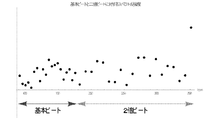
- FIG. 15 is a diagram illustrating the spectral intensities of the 1 ⁇ (basic beat) and the 2 ⁇ beat.
- FIG. 16 is a flowchart showing an example of calculation processing of period data and phase data in the second beat timing detection method.
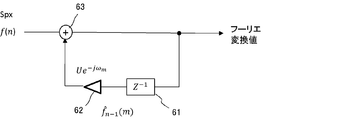
- FIG. 17 is a circuit diagram of Expression 3.
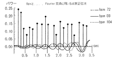
- FIG. 18 shows an example of Spx data and an attenuated sine wave having a BPM frequency used in the Fourier transform of Expression 3.
- FIG. 19 schematically shows a circuit for calculating the wavelet transform value w n . 20A, B, and C show the relationship between Spx data and a periodic Hann window sequence.
- FIG. 21 is a flowchart showing an example of the phase data calculation process.
- FIG. 22 is an explanatory diagram of wavelet transform values.
- FIG. 23 is a graph showing the beat intensity (IBS) for a certain music piece.
- IBS beat intensity
- a detection unit for detecting the beat timing of voice An image control apparatus including: the beat timing; and a control unit that changes the display mode of the video based on change information indicating a change content of the display mode of the video displayed on the display device.
- a detection unit that detects the beat timing of voice An image control device including a control unit that controls an image displayed on a display device based on the beat timing.
- audio includes sounds of musical instruments, human voices, musical compositions, and various sounds other than these.
- the voice may be a reproduced voice or a voice generated in real time.
- a video (moving image: movie, video) is composed of a plurality of still images (frame images) that are switched and displayed according to a predetermined frame rate.
- the video includes a case where there is no difference in motion vector or pixel value between the frame images for a predetermined period, that is, a case where a still image is displayed. Therefore, the image includes an image showing the movement of the object and the background in the screen, an image in which one still image is continuously displayed, and an image (slide show) in which a plurality of still images are switched and displayed over time.
- the video may be a playback video using information recorded on the medium or a real-time playback video using information obtained from the data stream.
- the beat timing may be a beat timing detected in advance or a beat timing detected in real time with respect to the output sound.
- Each of the “display mode change” and the “video control” can include at least one of the following (i) to (iv).
- the original image and the switching destination image may be switched alternately, or two or more switching destination images may be prepared.
- “Effect” is a visual effect (video effect) that appears on the display screen. For example, changing the brightness (blinking) or color (pixel value) of an image, inverting the pixel value, adding a 2D or 3D image (such as a figure), changing the degree of emphasis of an edge (outline) in the image, Includes image distortion (distortion).
- the parameters of the video relating to the effect are managed.
- the parameters relating to the effect include the brightness of the image, the pixel value, the degree of edge enhancement, and the like. However, other than these may be used.
- the effect is added or released. Alternatively, the effect is changed by changing the type of parameter.
- the length of time that the display mode is changed (video control) (time to switch to different video or time when one or more effects are added to the video) can be appropriately determined.
- the start timing of changing the display mode can be, for example, the time point of the beat timing or a predetermined time point before and after the beat timing. Further, the change start timing may be equal to the beat timing interval, n times (n is an integer of 2 or more), or 1 / n times.
- the end timing of the display mode change (video control) is the time when a certain time has elapsed from the start of the change, the time when the next beat timing is detected, the same time the beat timing interval, n times, or 1 / n times. Can be the point in time.
- the video control device when the video is switched from the video to a different video to change the display mode of the video (video control), the first video to which the audio is added and the first video A second video different from the video, and the control unit performs parallel reproduction processing of the first video and the second video, and also performs one of the first video and the second video. It is also possible to adopt a configuration in which the other of the first video and the second video that is ended during the reproduction is repeatedly played back.
- the video control device when the display mode of the video is changed (video control), the video is switched to a different video, the video is different from the first video. Including a second video, the control unit performs a parallel playback process of the audio, the first video, and the second video, and ends the first playback during the playback of the audio. It is also possible to adopt a configuration in which the image of or the second image is repeatedly reproduced.
- the control unit adds / changes / adds an effect to the video displayed on the display device as an addition of an effect to the video as a change of the display mode (control of the video). It is also possible to adopt a configuration in which at least one of the above is canceled.
- the effect is a visual effect that appears in the image (image effect). For example, changing the brightness of the video (including blinking), changing the color (pixel value) (inversion, etc.), and the two-dimensional or three-dimensional image or video (characters, graphics, symbols, patterns, signal waveforms such as voice, etc.) Addition or superimposition, changing the degree of emphasis of edges (contour lines) in an image, image deformation, addition of distortion, and the like are included.
- the control unit may adopt a configuration in which the parameter of the video relating to the effect is changed when the effect is added to the video as the display mode change (video control).
- the control unit may adopt a configuration in which the magnitude of the parameter is changed according to the waveform of a predetermined signal that changes with time.
- the predetermined signal is, for example, a voice signal, one signal other than voice, a signal obtained by mixing a voice signal with a signal other than voice signals, a signal formed by mixing two or more signals other than voice signals, and the like.
- a plurality of types of waveforms (patterns) may be prepared as the waveform of the signal used to change the size of the parameter, and the pattern may be selected by the user.
- a configuration may be adopted in which the control unit changes the display mode (controls the video) triggered by the detection of the above-mentioned beat timings for a plurality of consecutive times. Further, a configuration may be adopted in which the control unit changes the display mode (controls the image) a plurality of times within the beat timing interval. In this case, the video control intervals within the interval may or may not be equal.
- the control unit may adopt a configuration in which a display mode is changed (video control) at an interval of the finally detected beat timing with respect to a non-detected section in which the beat timing is not detected. Good. Further, the control unit determines a timing for changing the display mode (video control) based on an interval of the beat timing before and after the non-detection section in the non-detection section in which the beat timing is not detected. May be adopted. As the timing for changing the display mode (controlling the image), the average value of the intervals of the preceding and following beat timings may be adopted, or the value interpolated between the two may be adopted.
- the control unit with respect to the music that is sound, the interval between the first beat timing and the next beat timing from the first beat timing to the section from the start of the music to the first beat timing, the past, You may employ the structure which controls a video image every time it goes back to.
- a video control device, a video control method, a beat sound generation timing generation device, and a beat sound generation timing generation method according to the embodiment will be described below with reference to the drawings.
- the configuration of the embodiment is an example. The configuration is not limited to the embodiment.
- FIG. 1 shows a configuration example of an information processing device (computer) that can operate as a video control device.
- the information processing device may be a smart computer such as a smartphone or a tablet terminal, a general-purpose computer such as a personal computer, or a dedicated computer.
- the information processing device 1 may or may not be portable. In the following description, the case where the information processing device 1 is a smartphone will be described.
- the information processing device 1 includes a CPU (Central Processing Unit) 10, a ROM (Read Only Memory) 11, a RAM (Random Access Memory) 12, and a hard disk drive (HDD) 13 connected to a bus 3.
- the input device 14, the display device 15, and the communication interface (communication I / F) 16 are included.
- the information processing device 1 further includes a digital-analog converter (D / A) 17 and an analog-digital converter (A / D) 20 connected to the bus 3.
- An amplifier (AMP) 18 is connected to the D / A 17, and a speaker 19 is connected to the AMP 18.
- a microphone (MIC) 21 is connected to the A / D 20.
- the ROM 11 stores various programs executed by the CPU 10 and data used in executing the programs.
- the RAM 12 is used as a program development area, a work area of the CPU 10, a data storage area, and the like.
- the RAM 12 is used as a video RAM that draws a frame image of an image displayed on the display device 15.
- the HDD 13 stores programs, data used for executing the programs, music data, and the like.
- the music data is audio (acoustic) data having a predetermined audio file format such as MP3 or WAVE format.
- the format format of the audio file may be other than MP3 or WAVE format.
- the HDD 13 also stores a plurality of types of video files.
- the format of the video file does not matter.
- a video file may include both video data and audio data, or may not include audio data.
- the audio file and the video file have a time table (reproduction time information), and the video and audio are reproduced according to the time table.
- information (called beat timing information) indicating the timing of occurrence of beat (called beat timing) is stored in association with the reproduction time.
- beat timing information indicating the timing of occurrence of beat
- the ROM 11 and the RAM 12 are examples of a main storage device, and the HDD 13 is an example of an auxiliary storage device.
- the main storage device and the auxiliary storage device are examples of a storage device, a storage medium, or a memory.
- the ROM 11, the RAM 12, and the HDD 13 may be collectively referred to as “storage device 57”.
- the input device 14 includes keys, buttons, a touch panel, etc., and is used for inputting information (including instructions and commands).
- the display device 15 is used to display information.
- the communication I / F 16 is connected to the network 2 and controls processing related to communication.
- the CPU 10 can download desired music data (music signal) from the network 2 and store it in the HDD 13 according to an instruction input from the input device 14, for example.
- the CPU 10 performs various processes by executing the program. As the processing, in addition to the above-mentioned processing related to music download, processing related to audio and video reproduction is performed. Further, the CPU 10 performs a process of detecting a beat timing by using the beat timing information in the audio file or the video file, and a process of controlling the video based on the detected beat timing.
- the control of the image includes switching of the image displayed on the display device 15, addition, change, and release of the effect to the image.
- the CPU 10 when reproducing the music data, the CPU 10 generates digital data (digital signal) representing the sound of the music from the music data read from the HDD 13 to the RAM 12 by executing the program, and supplies the digital data to the D / A 17.
- the D / A 17 converts digital data representing sound into an analog signal by digital-analog conversion and outputs the analog signal to the AMP 18.
- the analog signal whose amplitude is adjusted by the AMP 18 is output from the speaker 19.
- the MIC 21 picks up, for example, a singing sound that accompanies (karaoke) the sound of the music output from the speaker 19.
- the analog audio signal picked up by the MIC 21 is amplified in amplitude by the AMP 18 and amplified by the speaker 19.
- the singing sound may be mixed with the music sound or may be output from separate speakers.
- the MIC 21 also collects a sound produced by playing a musical instrument (so-called live performance) and a reproduced sound of a music piece from an external device to expand the sound (output from the speaker 19) or record the sound.
- a performance sound signal picked up by the MIC 21 is converted into a digital signal by the A / D 20 and passed to the CPU 10.
- the CPU 10 converts the signal of the performance sound into a format according to the format of the audio file to generate an audio file, and stores it in the HDD 13.
- the information processing device 1 may include a drive device (not shown) for a disc type recording medium such as a compact disc (CD), a DVD, or a Blu-ray disc.
- a digital signal representing the sound of the music read from the disc type recording medium using the drive device may be supplied to the D / A 17 to reproduce the music sound or video.
- the beat timing may be detected for the sound signal of the music read from the disc-type recording medium.
- FIG. 2 is a diagram schematically showing a video control device (controller).
- the CPU 10 operates as the controller 50 by executing the program stored in the storage device 57 in FIG.
- the CPU 10 operates as a reproduction unit 51, a detection unit 52, and a control unit 53.
- the storage device 57 is provided with a first VRAM (VRAM 54), a second VRAM (VRAM 55), a beat information storage unit 58, and a change information storage unit 59.
- Audio data, video data, and video data with audio are input to the reproduction unit 51.
- the input audio data, video data, and video data with audio are stream reproduction data received from the network 2 even if the reproduction data is read from a medium (such as the storage device 57 or a disk storage device). It may be data related to.
- the reproduction unit 51 performs reproduction processing of audio and video based on the input audio data, video data, and video data with audio. That is, the reproduction unit 51 generates and outputs an audio signal based on the audio data included in the audio data and the video data with audio.
- the audio signal reaches the speaker 19 through the processing of the D / A 17 and the AMP 18 (not shown in FIG. 2), and the audio based on the audio signal is output from the speaker 19.
- the image in the embodiment does not matter whether a frame rate or a difference in pixel value between frames is generated. That is, the video includes a case where only one still image (image) is displayed, and a case where a plurality of still images (images) are switched over time (slide show).
- the reproducing unit 51 also draws an image (frame image) based on the video data and the video data with audio in the VRAM. Rewriting of the frame image drawn in the VRAM is performed at a predetermined frame rate.
- the signal of the frame image written in the VRAM is output to the display device 15, and the display device 15 displays the image based on the signal of the image (that is, the frame image switched according to the frame rate) on the screen of the display device 15. ..
- the playback unit 51 performs playback processing on a plurality of video data (video files) in parallel and draws a frame image in the corresponding VRAM.
- the reproducing unit 51 draws a video (an example of the first video) based on the first video data in the VRAM 54, and a video (an example of the second video) based on the second video data. Is drawn in the VRAM 55.
- One of the video signal output from the VRAM 54 and the video signal output from the VRAM 55 is output to the display device 15 via the switch 56.
- the control of the switch 56 is performed by the control unit 53.
- the detection unit 52 receives the identifier and the audio reproduction time data from the reproduction unit 51.
- the identifier is, for example, an identifier of audio data or video data with audio, but is not limited to these.
- the identifier and the audio reproduction time data are included in the audio data or the video data with audio input to the reproduction unit 51.
- the beat information storage unit 58 stores, in association with the identifier, information (referred to as beat information) indicating the timing of occurrence of beats (beat timing) on the time axis of the reproduction time of audio or video with audio. ..
- the detection unit 52 outputs a signal indicating the detection of the beat timing at the timing when the time on the reproduction time matches the time of the beat timing of the beat information, and supplies the signal to the control unit 53.
- the detection unit 52 has a configuration that detects a predetermined beat timing. However, the detection unit 52 may receive the audio signal from the reproduction unit 51 and calculate the beat timing in real time.
- the control unit 53 changes the display mode of the video displayed on the display device 15 based on the beat timing input from the detection unit 52 and the change information stored in the change information storage unit 59 (video Control).
- the change information is information relating to the change of the display mode of the image displayed on the display device 15, and includes information indicating the type of change of the display mode, information indicating the image or effect used for the change, and addition of the effect. It includes information indicating a parameter of a video to be used and information indicating a change start timing.
- the information indicating the type is one of “change of video”, “addition of effect to video”, “change of effect added to video”, and “cancellation of effect added to video”. This is information indicating that.
- the information indicating the video used for the change is information that identifies the video of the switching destination when the type of change is the video switching.
- One video or two or more videos to be switched to may be prepared.
- the information indicating the video used for the change is information for specifying the effect to be added / changed / released when the type of the change is addition of the effect, change of the effect, and cancellation of the added effect.
- the information indicating the parameter of the video used for adding the effect is information that identifies the parameter in the video used for adding the effect.
- the parameters are the luminance of the image, the degree of emphasis of the edge of the image, the degree of color (pixel value) inversion, the degree of posterization (tone change), and the like.
- the parameters are not limited to these.
- the variation amount of the parameter for adding the effect may be determined in advance by the user or the like.
- the fluctuation may be an increase, a decrease, or an increase or decrease.
- the size of the parameter may be changed according to the waveform of a predetermined signal.
- FIG. 3A shows the beat timing
- FIG. 3B shows the variation amount of the parameter according to the beat timing.
- the waveform shown in FIG. 3B is an example of a waveform of a predetermined signal, and is an example of a signal waveform other than voice.
- FIG. 3C shows a waveform of an audio signal, which is an example of the waveform of a predetermined signal. In the example shown in FIGS.
- the control unit 53 increases or decreases the parameter value in a mountain shape in a predetermined section before and after the beat timing in accordance with each beat timing, and in the other sections, the parameter strength is Take the default value (value when no effect is added).
- the start timing of the section in which the parameter increases or decreases may be the same as or later than the beat timing.
- the length of the parameter increase / decrease section can be changed as appropriate. Even if it does not occur at each beat timing but occurs once for several beat timings, it does not occur twice between beat timings. The above may occur.
- FIG. 3C shows an example of the waveform of the audio signal reproduced by the reproducing unit 51.
- the size of the parameter may be changed according to the amplitude of the voice signal.
- a signal obtained by mixing a signal indicating the parameter strength shown in FIG. 3B and a voice signal may be obtained, and the parameter strength may be changed according to the waveform (for example, the magnitude of amplitude) of the signal. ..
- the waveform for example, the magnitude of amplitude
- the information indicating the change start timing is information indicating the change start timing based on the beat timing. For example, it is possible to set the change to be started (changed) at the same times as the beat interval, n times, or 1 / n times.
- the beat interval is the same size
- the display mode is changed for each beat interval.
- the beat interval is n times (n ⁇ 2)
- the display mode is changed at an interval n times the beat interval.
- the beat interval is 1 / n times (n ⁇ 2)
- the display mode is changed at an interval of 1 / n times the beat interval.
- the switching or the effect may be continued from the detection of a beat to the detection of the next beat.
- the first beat timing is the switching or effect addition start timing
- the next beat timing is the switching or effect addition cancellation timing.
- the change start timing is determined so that the display mode is changed even in such a section in which no beat is detected (non-detection section). For example, as shown in FIG. 4, there is a section B in which no beat occurs between a section A in which the average value of beat intervals is “a” and a section C in which the average value of beat intervals is “c”.
- the control unit 53 takes the average value “b” of the value “a” and the value “c” for the section B, and causes the display mode to be changed at the beat interval of the average value “b”. ..
- control unit 53 does not necessarily have to change the display mode for the beat non-detection section.
- the control unit 53 may change the display mode based on the beat interval “a” in the section before the non-detection section (section A in the example of FIG. 4).
- a varying beat interval may be applied so that the beat intervals before and after the non-detection section (the values “a” and “c” in the example of FIG. 4) are interpolated.
- the intro part of the music corresponds to the beat non-detection section
- the beat interval detected first in the music is applied to the intro part so that the beat interval is connected to the beat timing detected first. Is determined.
- control unit 53 changes the display mode when the start timing of changing the display mode, which is determined based on the beat timing and the change information, arrives. For example, it is assumed that the reproducing unit 51 reproduces the first image using the VRAM 54 and the second image different from the first image using the VRAM 55.
- the second video is the video of the switching destination.
- control unit 53 controls the switch 56 according to the change information (change type: video switching) when the display mode change timing comes, and connects the output of the VRAM 54 to the display device 15.
- the state is switched to a state in which the output of the VRAM 55 is connected to the display device 15 for a predetermined time.
- the display mode of the display device 15 is switched from the first video display to the second video display.
- control unit 53 does not control the switch 56 if the type of display mode change is any of addition, change, and cancellation of the effect (the state in which the output of the VRAM 54 is connected to the display device 15 is maintained. ), And controls the playback unit 51 to add, change, or cancel effects.
- the value of the parameter of the image referred to by the reproducing unit 51 for drawing in the VRAM 54 (for example, the degree of edge emphasis) is rewritten to the value when the effect is added or the value when the effect is released.
- the control unit 53 cancels the first effect (returns the emphasis degree to the original value) while the first effect (for example, the enhancement degree of the edge is being increased) is being performed, and the first effect A different second effect (for example, increasing the brightness value of the image) can be added. As a result, the effect is changed. It should be noted that a second effect different from the first effect may be applied in the added state of the first effect. Further, an effect may be added to the frame image drawn in the VRAM 55 and the frame image may be connected to the display device 15.
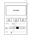
- FIG. 5 shows an example of a user interface (UI) of the information processing device 1.
- UI user interface
- FIG. 5 a screen 15A of the display device 15 is shown.
- the display device 15 has a touch panel, and various buttons (operators) displayed on the screen 15A serve as the input device 14.
- the screen 15A includes a display area 21 for video (first video), selection buttons 22, 23 and 24 for video to be switched to (second video), and a slide button 25 for increasing / decreasing parameter intensity. , A beat interval adjusting unit 26, and an indicator 27 indicating the reproduction time of the first video.
- the selection buttons 22, 23, 24 are selection buttons for images to be switched when the display mode is changed, and in the example shown in FIG. 5, a maximum of three images can be entered as switching destination images.
- the selection buttons 22, 23, and 24 may be configured to display a thumbnail image or video showing the video of the switching destination.
- the slide button 25 can operate the strength of the parameter by moving a linear operator (shown by a circle) left and right. In the example of FIG. 5, the strength increases as the operator is located on the right side, and the strength decreases as the operator is located on the left side.
- the parameter assigned to the slide button 25 can be appropriately selected. In the present embodiment, the degree of emphasis of the edge of the video displayed in the display area 21 can be changed by operating the slide button 25.
- the beat interval adjustment unit 26 is composed of a plurality of buttons for selecting the intervals at which the display mode is changed with respect to the beat intervals detected by the detection unit 52.
- the scaling factor for the beat interval can be selected from 1/8, 1/4, 1/2, 1, 2, 3, 4.
- the same magnification (1) is selected and the selected magnification is highlighted.
- the indicator 27 shows the time axis indicating the reproduction time of the video shown in the display area 21 by a straight line, and displays how the pointer (indicated by a triangle) indicating the current time in the reproduction time moves on the time axis.
- the user can select or determine the video to be switched, the parameter strength, and the switching execution timing (execution interval).
- the result of the determination is stored as change information in the change information storage unit 59 (storage device 57).
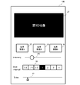
- FIG. 6 shows another example of the user interface (UI) of the information processing device 1.
- the UI (referred to as the first UI) displayed on the screen 15A shown in FIG. 5 is the UI for switching the video as the change of the display mode.
- a UI (referred to as a second UI) displayed on the screen 15B shown in FIG. 6 is a UI for adding an effect as a change of the display mode.
- the selection buttons 22, 23, 24 of the switching destination video are changed to selection buttons 32, 33, 34 for selecting the type of effect to be added to the video.
- the display area 21, the slide button 25, the adjustment unit 26, and the indicator 27 are the same as those in the first UI (FIG. 5).
- the type of effect can be assigned to the selection buttons 32, 33, 34.
- inversion of pixel values can be assigned to the selection button 32
- posterization gradient change
- edge enhancement can be assigned to the selection button 34.
- the selection buttons 32, 33, and 34 can display thumbnail images or videos when the effect is added. It is also possible to specify the effect to be changed when changing the effect by using the selection buttons 32, 33 and 34. For example, using the select button 32 to specify inversion as the first effect, and using the select button 33 to specify gradation change as the second effect, the effect to be applied is reversed from the inversion at the execution timing of the change. The gradation may be changed.
- the image shown in the display area 21 of FIG. 6 is an inverted image of the image shown in the display area 21 of FIG.
- the audio waveform may be displayed in real time so as to be superimposed on the image displayed in the display area 21.
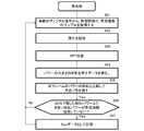
- FIG. 7 is a diagram illustrating an example of processing in the controller 50.
- change information is set.
- the user uses the input device 14 and the display device 15 to specify a video (first video) to be displayed in the display area 21 of the display device 15.
- a video with audio is designated as the first video.
- the CPU 10 displays the screen 15A (FIG. 5) or the screen 15B (FIG. 6) on the display device 15 in response to the calling operation using the input device 14 by the user.
- the user uses the screen 15A or the screen 15B to perform setting input of information (change information) relating to the change of the display mode.
- the user uses the input device 14 to specify an image to be displayed in the display area 21 of the display device 15. Subsequently, the user uses the selection buttons 22 to 24 on the screen 15A to input the designation of the switching destination video (second video). Further, the user uses the adjustment unit 26 to specify the execution timing (implementation interval) of switching the video. Information indicating the switching destination video and the switching execution interval is stored in the storage unit 59 as change information.
- the playback unit 51 starts playback processing for video with audio (S002).
- the reproduction process of the video of the switching destination is also started, and the drawing on the VRAM 54 and the VRAM 55 is started.
- the control unit 53 controls the switch 56 so that the switch 56 selects the output of the VRAM 54.
- the image from the VRAM 54 is displayed in the display area 21 of the display device 15.
- the reproduction unit 51 performs the reproduction processing of the audio added to the video, and the audio is output from the speaker 19.
- S004 it is determined whether or not there is a setting change of the change information, and if there is a setting change, the setting change of the change information is reflected (change information is overwritten).
- the slide button 25 and the adjusting unit 26 can be operated even during reproduction of the video.
- the results of these changes are reflected in the change information stored in the storage unit 29 in S004 (the change information is updated).
- the update processing of the change information accompanying the operation of the first or second UI may be performed by interrupt processing at any time.
- the detection unit 52 detects the beat timing by comparing the reproduction time information and the beat information (S005).
- Information indicating the detection of the beat timing is supplied from the detection unit 52 to the control unit 53.
- the control unit 53 uses the information indicating the change execution timing (execution interval) included in the change information based on the change information (type of change in display mode: video switching) stored in the storage unit 59.
- the switch 56 is controlled to switch to a state in which the output of the VRAM 55 (the signal of the video of the switching destination) is output to the display device 15. As a result, the image of the switching destination is displayed in the display area 21 for a predetermined time, instead of the image with the audio (S006).
- S007 it is determined whether the video playback time has expired. This determination is performed for both the video with audio and the video of the switching destination.
- the reproduction unit 51 repeats reproduction of the video for which the reproduction time has expired (S008). For example, when the reproduction time of the video with audio (first video) is longer than the reproduction time of the switching destination video (second video) and the reproduction time of the second video has expired, the reproduction of the first video is performed. If the time has not expired, the repeated reproduction of the second video is executed.
- the reproducing unit 51 performs repeated reproduction when the reproduction time of the first video expires ( S007, S008). However, as described above, when it is determined that the reproduction time of the first video has expired, the reproduction unit 51 may not reproduce the first video, and the process illustrated in FIG. 7 may end.
- the reproducing unit 51 starts reproducing the video with audio in response to the user's operation of the reproduction button
- the output of the VRAM 54 is connected to the display device 15 and the video is displayed in the display area 21.
- the control unit 53 draws the frame image of the video with audio to the reproduction unit 51 at the timing based on the beat timing detected by the detection unit 52 and the information indicating the execution interval of the effect included in the change information. Change the parameters related to. For example, if the effect type is inversion, the control unit 53 changes the pixel value of the image drawn by the reproduction unit 51 to a value obtained by inverting the pixel value before addition. As a result, the image when the pixel values are inverted is displayed in the display area 21 for a predetermined time.
- the effect type is gradation change, an image with a reduced number of gradations is displayed in the display area 21 for a predetermined time. If the effect type is the edge emphasis degree, the edge emphasized image is displayed in the display area 21 with the edge emphasis degree set using the slide button 25. The effect type may be changed or the added effect may be canceled at the execution timing subsequent to the execution timing of adding the certain effect.
- the first video is a video with audio
- the first video is video based on data of only video
- the audio data is independent (separate) data from the video. May be In this case, the reproducing unit 51 reproduces the audio in synchronization with the reproduction of the first video.
- the controller 50 is configured using the CPU 10 and the storage device 57.
- the CPU 10 is an example of a processor, and the processing performed by the processor may be performed by a plurality of CPUs (processors) or a multi-core CPU.
- the processing performed by the processor is a processor (DSP (Digital Signal Processor) or GPU (Graphical Processing Unit), etc.) other than the CPU, an integrated circuit (ASIC (Application Specific Integrated Circuit)) or FPGA (Field Programmable Gate Array) other than the processor.
- DSP Digital Signal Processor
- ASIC Application Specific Integrated Circuit
- FPGA Field Programmable Gate Array
- MPU Micro Processing Unit
- SoC System-on-a-Chip
- the display mode of the video displayed in the display area 21 of the display device 15 is automatically set based on the beat timing of the sound and the change information related to the change of the display mode of the video displayed on the display device 15. Will be changed (images are switched, effects are added, etc.). As a result, it is possible to reduce the work load for displaying in the display area 21 the manner in which the display mode of the video is changed in accordance with the beat of the sound as in the conventional case.
- the beat timing with respect to the sound is determined in advance, stored as the beat information in the storage unit 58, and used by the detection unit 52 to detect the beat timing.
- the second embodiment will describe a beat timing detection method in which the detection unit 52 can detect the beat timing in real time from a voice signal.
- a first beat timing detection method (first method) generates timing information governing the beat of the music and a plurality of intensity data indicating power at the timing from the input music data, Calculating the beat cycle and phase of the music using the intensity data, and detecting the beat sound generation timing based on the beat cycle and phase.
- first method from the input music data, timing information that governs the beat of the music, a generation unit that generates a plurality of intensity data indicating power at the timing, and the plurality of intensity data are used.
- a beat timing detection device is used that includes a calculation unit that calculates the cycle and phase of the beat of the song, and a detection unit that detects the timing at which the beat sound is generated based on the cycle and phase of the beat.
- the beat timing detection device may further include a reproduction processing unit that performs reproduction processing of the beat sound according to the generation timing of the beat sound.
- the calculation unit determines a BPM (Beats Per Minute) for the plurality of intensity data based on the timing indicated by the plurality of intensity data, and sets one cycle of the BPM as the cycle of the beat.
- the relative position of the generation timing of the beat sound in the sine wave indicating the BPM is calculated as the phase of the beat, and the detection unit obtains a count value indicating the cycle of the beat and the phase of the beat.
- a configuration may be adopted in which the count value is counted using a counter that increments for each sample of the sampling rate, and the timing at which the counter value reaches the count value is detected as the beat sound generation timing. Good.
- the calculation unit calculates one cycle of the BPM when the value of the Fourier transform data obtained by the Fourier transform performed for each of the plurality of intensity data and each of the plurality of BPMs is maximum. You may employ
- the calculating unit calculates the frequency of the first BPM. Using the second BPM and the value of the Fourier transform data calculated using the first BPM to obtain the Fourier transform data for at least one second BPM having an integral multiple frequency.
- a configuration may be adopted in which a value obtained by adding the calculated value of the Fourier transform data at a predetermined ratio is used as the value of the Fourier transform data for the first BPM.
- the generation unit acquires a frame composed of a predetermined number of consecutive sound samples from the input music data, thins out the samples in the frame, and performs fast Fourier transform on the thinned samples. While performing the processing for obtaining the data indicating the sum of the powers for each frequency bandwidth obtained by the fast Fourier transform at a predetermined interval, the state in which the data indicating the sum of the powers having a value larger than itself does not appear You may employ
- the information processing device 1 shown in FIG. 1 is applicable to a beat timing detection device.
- the CPU 10 executes the program stored in the storage device 57 to detect the beat timing of the voice (generate the beat sound generation timing).
- FIG. 8 is a diagram showing a configuration example of the beat timing detection unit.
- the CPU 10 operates as the beat timing detection unit 100 shown in FIG.
- the beat timing detection unit 100 is included in the detection unit 52 in the first embodiment. Alternatively, it can be replaced with the detection unit 52.
- the beat timing detection unit 100 includes a time sparse data (expressed as “Spx data”: equivalent to intensity data) generation unit 101, a buffer 102, a period data and phase data calculation unit 103, and a beat timing detection unit 104. ..
- the beat timing is notified to the control unit 53 (FIG. 1).
- the control unit 53 uses the beat timing for changing the display mode (video control). The operation and processing of the control unit 53 have been described in the first embodiment, and thus the repetitive description will be omitted.
- the beat timing is input to the beat sound reproduction processing unit 105 as a beat sound generation timing (output instruction).
- the reproduction processing unit 105 performs the reproduction processing of the beat sound according to the generation timing.
- the operation as the reproduction processing unit 105 is performed by the CPU 10, for example.
- the buffer 102 is provided in a predetermined storage area of the RAM 12 or the HDD 13, for example.
- the Spx data generation unit 101 generates and outputs Spx data using digital data that represents the sound of a song.
- the buffer 102 stores at least Spx data for a predetermined time (corresponding to a plurality of intensity data). In this embodiment, 6 seconds is illustrated as the predetermined time, but the predetermined time may be longer or shorter than 6 seconds.
- the calculation unit 103 calculates beat cycle data and phase data using a set of Spx data for a predetermined time accumulated in the buffer 102.
- the generation timing detection unit 104 detects the beat timing using the cycle data and the phase data.
- a digital signal representing the sound of music data (data sent to the D / A 17 for audio output) related to reproduction is input to the generation unit 101.
- the digital signal representing the sound may be obtained by reproducing the music data stored in the HDD 13 or obtained by A / D conversion of the audio signal picked up by the MIC 21.
- the digital data representing the sound is stored in the RAM 12 and used for the processing of the generation unit 101.
- the digital data representing sound is a set of sample data (normally, the voltage value of the analog signal) sampled from the analog signal at a predetermined sampling rate.
- the sampling rate is 44100 Hz.
- the sampling rate can be appropriately changed as long as a desired FFT resolution can be obtained.
- FIG. 9 is a flowchart showing a processing example of the generation unit 101.
- Digital data digital signal representing the sound of the musical composition, which is sent to the D / A 17 for musical sound output (reproduction), is input to the generator 101.
- the generation unit 101 acquires a predetermined number of samples (called "frames") from the input digital data (S01).
- the predetermined number is 1024 in this embodiment, but may be larger or smaller than this.
- the sample acquisition is performed at predetermined intervals.
- the predetermined interval is, for example, 5 ms, but may be longer or shorter than this.
- the generation unit 101 performs thinning processing. That is, the generation unit 101 thins out 1024 samples by 1/4 to obtain 256 samples. The decimation may be other than the 1/4 decimation.
- the generation unit 101 performs a fast Fourier transform (FFT) on 256 samples, and from the result of FFT (power for each frequency bandwidth), data indicating the magnitude of power in units of frames (power Data) is obtained (S04). Since the power is represented by the square of the amplitude, the concept of “power” includes the amplitude.
- FFT fast Fourier transform
- the power data is, for example, the sum of powers obtained by performing FFT on 256 samples.
- the power of the corresponding bandwidth in the previous frame is subtracted from the power of each frequency bandwidth of the current frame, and when the value is positive (the power is increasing), the power values are summed up. Values that are left for calculation and not negative (subtracted value is negative (decreased power)) may be ignored. This is because it is highly likely that the beat is where the increase in power is large.
- the value used to calculate the total sum is the total power of the current frame, but the power of the previous frame is subtracted from the power of the previous frame.
- the value may be the sum of positive powers or the difference obtained by subtracting the power of the previous frame from the power of the current frame.
- the above difference may be calculated only for frequencies lower than a predetermined frequency. Frequencies above a predetermined frequency may be cut using a low pass filter.
- the power data is stored in the RAM 12 or the HDD 13 in frame units.
- the generation unit 101 compares the magnitudes of power sums (peak values) each time the power data in units of frames is created, and leaves the larger one, and discards the smaller one (S05).
- the generation unit 101 determines whether a sum total larger than the sum total left in S05 has not appeared for a predetermined time (S06).
- the predetermined time is, for example, 100 ms, but may be longer or shorter than 100 ms.
- the generation unit 101 extracts the data indicating the total sum of the powers as Spx data, and stores (stores) the data in the buffer 102 (S07). ..
- the Spx data is data in which the peak value of digital data indicating a musical sound is extracted at 100 ms intervals, and is information indicating the timing (timing information) that controls the beat of the music and the power at that timing. is there.
- a plurality of Spx data are stored in the buffer 102.
- the generation unit 101 repeats the processing from S01 to S06.
- FIG. 10A shows a digital signal of 12 seconds of music input to the generation unit 101
- FIG. 10B shows an example of Spx data generated from the digital signal of the music shown in FIG. 10A
- the horizontal axis of the graph shown in FIG. 10B is time, and the vertical axis is power.
- a vertical line with a black circle at the upper end represents individual Spx data obtained from the digital signal of the music piece shown in FIG. 10A
- the position of the horizontal axis (time axis) represents timing
- the vertical line Length indicates power.
- FIG. 11 is a flowchart showing a processing example of the calculation unit 103.
- the new Spx data generated by the generation unit 101 arrives at the buffer 102 and is accumulated.
- Spx data (corresponding to a plurality of intensity data) for a predetermined time of the Spx data accumulated in the buffer 102 is acquired from the buffer 102.
- the predetermined time is, for example, 6 seconds, but may be longer or shorter than 6 seconds as long as the beat cycle and phase can be obtained.
- the subsequent processes of S12 to S16 are processes performed using the 6 seconds of Spx data acquired in S11.
- the Spx data for 6 seconds is subjected to Fourier transform corresponding to a predetermined number (for example, 20) of BPM (Beats Per Minute: indicating tempo (rhythm speed)), and the beat cycle (BPM The cycle) and the beat phase (beat sound generation timing) are calculated.
- BPM Beats Per Minute: indicating tempo (rhythm speed)
- the frequency (BPM frequency) corresponding to a predetermined number of Spx data for 6 seconds, for example, 20 corresponding to BPM 86 to 168 (BPM frequency) f ⁇ 86,90,94, ..., 168 ⁇ /
- BPM frequency BPM frequency
- f ⁇ 86,90,94, ..., 168 ⁇ /
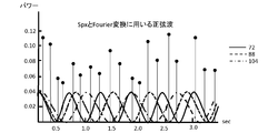
- FIG. 12 is a diagram showing an example of a sine wave having Spx data and a BPM frequency used for Fourier transform.
- a sine wave of BPM 72 shown by a solid line
- a sine wave of BPM 88 shown by a broken line
- a sine wave of BPM 104 shown by a dashed line
- the value of the Fourier transform data c (i) is calculated by the following equation 1. The value of BPM and the number thereof can be changed appropriately.
- t (k) in Expression 1 is the time position in the past 6 seconds in which the Spx data exists, and the unit is seconds.
- x (t (k)) represents the value (peak value size) of Spx data at that moment.
- f (i) is the BPM frequency, for example, BPM 120 is 2.0 Hz.
- the beat timing indicates a position relative to the generation timing of beats that periodically arrive.
- phase value ⁇ By calculating the phase value ⁇ , it is possible to know the relative position of the beat generation timing with respect to the sine wave of the BPM, that is, how much the beat generation timing is delayed with respect to one cycle of the BPM.
- FIG. 13 illustrates the relationship between the cosine wave (the real part of EXP (2 ⁇ jft)) indicating BPM and the beat generation timing.
- the number of Spx data is 4 and its BPM is 72.
- Each of the Spx data shown in FIG. 13 is a value (phase) of c (i) obtained by using Expression 2, and indicates a beat generation timing.
- the Spx data has a beat generation timing interval.
- the beat generation timing is a timing obtained by calculating the phase value ⁇ and delayed by ⁇ / 2 from the cosine wave having the BPM frequency.
- the calculation unit 103 sets the number of samples in one cycle of BPM as cycle data (S15).
- the cycle data is 25442 [pieces] and the phase value ⁇ is 0.34 [rad]
- the calculation unit 103 outputs the period data and the phase data (S16).
- the calculation unit 103 repeats the processing of S11 to S16 every time 6 seconds of Spx data is accumulated. This makes it possible to follow changes in the rhythm of the music.
- FIG. 14 is a flowchart showing an example of beat timing detection processing by the detection unit 104.
- the detection unit 104 determines whether new period data and phase data have been provided from the calculation unit 103. If new period data and phase data are provided, the process proceeds to S22, and if not, the process proceeds to S23.
- the detection unit 104 adopts the new cycle data and the phase data for detecting the beat generation timing, and discards the old cycle data and the phase data.
- the samples of the frames forming the Spx data are in a state in which a delay of 100 ms is given. Therefore, here, the music and rhythm being played or reproduced, and a hand clap sound described later are generated.
- the time adjustment (phase adjustment) is performed so that Then, the process proceeds to S23.
- the counter is set using the number of samples of the period data and the number of samples of the phase data.
- the detection unit 104 has a counter that counts up (increments) for each sample of the sampling rate (interval of voltage check of the analog signal according to the sampling rate), and the count value of the counter for each sample. Increment.
- the process waits until the count value becomes equal to or more than a predetermined value (a value indicating the sum of the number of samples of phase data (count value) and the number of samples of cycle data (count value)) (S24).
- the detection unit 104 detects a beat sound generation timing (beat timing) based on the prediction (S25).
- the detection unit 104 notifies the control unit 53 of the occurrence of beat timing and outputs a beat sound output instruction (S25).
- the control unit 53 performs the operation (change of display mode) described in the first embodiment based on the beat timing.
- the reproduction processing unit 105 sends to the D / A 17 the digital data of the beat sound (for example, hand clap sound) stored in advance in the ROM 11 or the HDD 13 according to the output instruction.
- the digital data is converted into an analog signal by the D / A 17, amplitude-amplified by the AMP 18, and then output from the speaker 19.
- the hand clap sound is output overlaid on the music being reproduced or played.
- the reproduced or played (past) music is input to the generation unit 101, and the generation unit 101 generates Spx data.
- Spx data is accumulated in the buffer 102, and the calculation unit 103 calculates the beat cycle and phase from a plurality of Spx data for a predetermined time (6 seconds), and adjusts the beat cycle and phase according to the music (voice) being reproduced or played.
- the detection unit 104 detects and outputs the beat timing.
- the control unit 53 can change the display mode based on the beat timing.
- the reproduction processing unit 105 can output a hand clap sound that matches the rhythm of the music being reproduced or played.
- the automatic output of the hand clap sound is performed by a simple algorithm with a small calculation amount, such as the generation of the Spx data described above, the calculation of the beat cycle and the phase based on the Fourier transform data, and the counting of the counter value. be able to. As a result, it is possible to avoid an increase in the load on the processing execution subject (CPU 10) and an increase in memory resources. Further, since the amount of processing is small, it is possible to output the clap sound without any delay with respect to the reproduced sound and the performance sound (a person cannot recognize it even if there is a delay).
- the processing performed by the beat timing detection unit 100 may be performed by a plurality of CPUs (processors) or a multi-core CPU. Further, the processing performed by the beat timing detection unit 100 is performed by a processor (DSP, GPU, etc.) other than the CPU 10, an integrated circuit (ASIC, FPGA, etc.) other than the processor, or a combination of the processor and the integrated circuit (MPU, SoC, etc.). It may be executed.
- processors DSP, GPU, etc.
- ASIC integrated circuit
- FPGA field-programmable gate array
- MPU integrated circuit
- FIG. 15 is a diagram illustrating the spectral intensities of the 1 ⁇ (basic beat) and the 2 ⁇ beat.
- the value obtained by adding the spectral intensities of 1 time, 2 times, and 4 times at a predetermined ratio is used to determine the BPM.
- the spectral intensity of BPM 91 an example of the first BPM
- the spectral intensity of BPM 182 and BPM 364 an example of at least one second BPM
- That value is used as the absolute value of c (i) for BPM 91.
- the power for BPM corresponding to subdivided eighth notes and 16th notes is greater than the basic beat symbolized by quarter notes, so double or quadruple the power It is possible to select a better BPM by reflecting it on the strength of.
- 2 times or 4 times is illustrated as an example of the integral multiple, but the same effect can be obtained even if the integer multiple of 3 times or 5 times or more is obtained.
- the configurations shown in the embodiments can be appropriately combined without departing from the purpose.
- the second beat timing detection method (second method)
- the beat timing detection unit 100 generates timing information for controlling the voice beat and intensity data indicating the power at the timing from the input voice data.
- the processing, the processing of calculating the cycle and phase of the audio beat using the intensity data, and the processing of detecting the beat timing based on the cycle and phase of the beat are performed.
- the second method is an improvement of the first method.
- the second method is the same as the first method with respect to the generation of Spx data, but differs with respect to the calculation of the period data and the phase data as follows.
- FIG. 16 is a flowchart showing an example of calculation processing of period data and phase data in the second beat timing detection method.
- the new Spx data generated by the generation unit 101 arrives at the buffer 102.
- the calculation unit 103 obtains Fourier transform data corresponding to a predetermined number of BPMs.
- a predetermined number for example, 20 to 40
- BPM Beats Per Minute: indicates the tempo (rhythm speed)
- Corresponding Fourier transform was performed (FIG. 11, S12).
- the Fourier transform having the attenuation term U k is used instead of the Fourier transform used in the first method.
- the formula (Formula 3) of the Fourier transform is shown below.
- U represents the amount of attenuation per sample and is a number close to 1.
- U indicates the rate of forgetting the past data.
- the interval is past infinity.
- FIG. 17 is a circuit diagram of Expression 3.
- the past signal f n-1 (m) delayed by the present delay block (Z ⁇ 1 ) 61 is multiplied by the attenuation term Ue ⁇ j ⁇ m in the multiplier 62, and the present signal f n in the adder 63. (N) is added. In this way, the Fourier transform value per sample is obtained.
- the Fourier transform value of Expression 3 can be expressed by Expression 4 and Expression 5 below.
- Expression 3 (the circuit shown in FIG. 17) is not used, Can be used to obtain Fourier transform values for L samples.
- the value of q m L in Expression 6 can be easily obtained using Expression 7. Note that f (n) is the value of Spx data, L is the arrival interval of Spx data, U is the attenuation coefficient, and ⁇ m is the angular frequency per sample corresponding to BPM.
- FIG. 18 shows an example of Spx data and a damped sine wave having a BPM frequency used in the Fourier transform of Expression 3.
- the wave with the longest cycle is the wave of BPM 72
- the next wave is the wave of BPM 88
- the wave with the shortest cycle is the wave of BPM 104.
- a predetermined number of BPMs for example, 20 are prepared, and the Fourier transform value using Equation 3 described above is obtained for each BPM.
- the number of BPMs may be more or less than 20.
- the second method does not require accumulating Spx data for a predetermined period (6 seconds). Therefore, the storage area of the memory (storage device 57) for accumulating Spx data can be effectively used. Further, in the first method, the product-sum calculation of a plurality of BPM ⁇ Spx data numbers was performed, whereas in the second method, the calculation of Formula 3 is performed for each BPM, so that the calculation amount is significantly increased. Can be reduced.
- the calculation unit 103 obtains a predetermined number (for example, 5) of wavelet transform values corresponding to a predetermined number (for example, 20) of BPM.
- FIG. 19 schematically shows a circuit for calculating the wavelet transform value w n .
- the circuit has a configuration in which a multiplier 64 is added to the circuit for calculating the Fourier transform value shown in FIG.
- the multiplier 64 multiplies the Spx data by a periodic Hann window sequence whose period is the number of samples corresponding to the BPM value.
- the Fourier transform of Expression 3 described above is performed on the output of the multiplier 64, and the wavelet transform value w n is output.
- the Hann window is an example of the window function, and in addition to the Hann window, a triangular window or a Hamming window can be applied.
- the wavelet transform value w n is obtained for each BPM at a timing shifted by 1 ⁇ 5 cycle of each BPM. That is, a periodic Hann window sequence shifted by 1 ⁇ 5 cycle of BPM is prepared, and the wavelet transform value ⁇ w n ⁇ 0 ⁇ n ⁇ 5 corresponding to each periodic Hann window sequence is obtained.
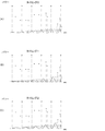
- FIG. 20A, 20B, and 20C show the relationship between Spx data and a periodic Hann window sequence.
- FIG. 20A shows a damped sine wave indicating a periodic Hann window sequence at timing 0 according to a certain BPM by a thick line, and a damped sine wave indicating a periodic Hann window sequence other than timing 0 by a thin line.
- FIG. 20B shows a damped sine wave showing a periodic Hann window sequence at timing 1 (advancing by 1/5 period from timing 0) according to a certain BPM by a thick line, and a periodic Hann window sequence other than timing 1 is shown.
- the attenuated sine wave indicating is shown by a thin line.
- 20C shows a damped sine wave showing a periodic Hann window sequence at timing 2 (advancing 1/5 period from timing 1) according to a certain BPM by a thick line, and a periodic Hann window sequence other than timing 1 is shown.
- the attenuated sine wave shown is indicated by a thin line.
- the calculation unit 103 determines the BPM corresponding to the Fourier transform value having the maximum absolute value among the Fourier transform values corresponding to the plurality of BPMs as the BPM of the Spx data (beat). To do. In addition, the calculation unit 103 determines the number of samples of one cycle of the beat of the determined BPM as the beat cycle data (S54).
- the calculation unit 103 calculates a phase value from a predetermined number of wavelet transform values corresponding to BPM and converts it into a sample value for the periodic data. That is, the calculation unit 103 obtains n when the absolute value of the wavelet transform value w n becomes maximum (S551 in FIG. 21) and obtains the phase value Arg (w n ) corresponding to n (S552 in FIG. 21). .. The calculation unit 103 converts the phase value into a sample value (phase data) for the cycle data (S55), and outputs the cycle data and the phase data (S56).
- FIG. 22 is an explanatory diagram of wavelet transform values.
- the wavelet transform values are unevenly distributed in time and have complex phase information. That is, the wavelet transform value has a Hann window curve, a curve related to the product of the Hann window and the real part (cosine), and a curve related to the product of the Hann window and the imaginary part (sine).
- the storage capacity and the amount of calculation required for the processing can be reduced and the detection accuracy of the phase (beat timing) is improved as compared with the first method.
- the beat intensity can be calculated, for example, by the controller 50 in the first embodiment or the beat timing detection unit 100 (for example, the calculation unit 103) in the second embodiment.
- the average of the beat intervals (the number of samples) of the past 5 times is set to m.
- the fluctuation rate Qrate of the cycle from the new beat interval I can be calculated using the following equation 8. It can be said that the smaller the variation rate Qrate, the more stable the beat.
- FIG. 23 is a graph showing IBS for a certain song. About 12 seconds after the performance starts, the tempo is uncertain. In this case, IBS starts at a small value and rises to around 1.0 when the tempo becomes clear.
- the detected beat timing and beat interval can represent how much the music can be trusted. For example, in the first embodiment, a section in which IBS is less than a predetermined value (eg, 0.6) can be determined as a beat non-detection section.
- a predetermined value eg, 0.6
Landscapes
- Engineering & Computer Science (AREA)
- Multimedia (AREA)
- Physics & Mathematics (AREA)
- Acoustics & Sound (AREA)
- Signal Processing (AREA)
- Controls And Circuits For Display Device (AREA)
Abstract
映像制御装置は、音声のビートタイミングを検出する検出部と、ビートタイミングと、表示装置に表示されている映像の表示態様の変更内容を示す変更情報とに基づいて、映像の表示態様の変更を行う制御部とを含む。
Description
本発明は、映像制御装置、及び映像制御方法に関する。
従来、外部演奏音の脈動から検出した拍位置を入力された補正情報に基づいて修正し、外部演奏音に同期して歌詞トラックを読み出して歌詞テロップを生成するコンテンツ再生装置がある(例えば、特許文献1)。また、オーディオの高域および/または低域のピーク値から閾値を設定し、オーディオのレベルが閾値を超える時間間隔に応じて映像の表示を切り替える画像閲覧装置がある(例えば、特許文献2)。また、音声と映像を含む複数のメディアをビートを同期させてミックスする方法がある(例えば、特許文献3、4)。また、太鼓を打撃するアニメーションを表示するタイミング制御装置がある(例えば、特許文献5)。
従来技術では、音声に合わせて映像の制御を行う場合、ユーザが音声を聞きながらマニュアルで行う必要があった。本発明は、音声に合わせて表示装置の表示内容を変化させることを可能とする技術を提供することを目的とする。
本発明の一態様は、
音声のビートタイミングを検出する検出部と、
前記ビートタイミングと、表示装置に表示されている映像の表示態様の変更内容を示す変更情報とに基づいて、前記映像の表示態様の変更を行う制御部と
を含む映像制御装置である。
音声のビートタイミングを検出する検出部と、
前記ビートタイミングと、表示装置に表示されている映像の表示態様の変更内容を示す変更情報とに基づいて、前記映像の表示態様の変更を行う制御部と
を含む映像制御装置である。
本発明に係る映像制御装置において、前記制御部が、前記表示態様の変更として、
(i)前記映像から異なる映像への切り替え、
(ii)前記映像に対する効果の付加、
(iii)前記映像に付加する効果の変更、及び
(iv)前記映像に付加した効果の解除
のうちのいずれかを行う構成を採用してもよい。
(i)前記映像から異なる映像への切り替え、
(ii)前記映像に対する効果の付加、
(iii)前記映像に付加する効果の変更、及び
(iv)前記映像に付加した効果の解除
のうちのいずれかを行う構成を採用してもよい。
本発明に係る映像制御装置において、前記表示態様の変更として、前記映像から異なる映像への切り替えが行われる場合において、
前記映像が、前記音声が付加されている第1の映像と、前記第1の映像と異なる第2の映像とを含み、
前記制御部は、前記第1の映像と前記第2の映像との並列な再生処理を行うとともに、前記第1の映像及び前記第2の映像の一方の再生中に終了した前記第1の映像及び前記第2の映像の他方についての繰り返し再生を行う構成を採用してもよい。
前記映像が、前記音声が付加されている第1の映像と、前記第1の映像と異なる第2の映像とを含み、
前記制御部は、前記第1の映像と前記第2の映像との並列な再生処理を行うとともに、前記第1の映像及び前記第2の映像の一方の再生中に終了した前記第1の映像及び前記第2の映像の他方についての繰り返し再生を行う構成を採用してもよい。
本発明に係る映像制御装置において、前記表示態様の変更として、前記映像から異なる映像への切り替えが行われる場合において、
前記映像が、第1の映像と、前記第1の映像と異なる第2の映像とを含み、
前記制御部は、前記音声と、前記第1の映像と、前記第2の映像との並列な再生処理を行うとともに、前記音声の再生中に終了した前記第1の映像又は前記第2の映像についての繰り返し再生を行う構成を採用してもよい。
前記映像が、第1の映像と、前記第1の映像と異なる第2の映像とを含み、
前記制御部は、前記音声と、前記第1の映像と、前記第2の映像との並列な再生処理を行うとともに、前記音声の再生中に終了した前記第1の映像又は前記第2の映像についての繰り返し再生を行う構成を採用してもよい。
本発明に係る映像制御装置において、前記制御部が、前記表示態様の変更として、前記映像に対する効果の付加を行う場合に、前記効果に係る前記映像のパラメータを変更する構成を採用してもよい。
本発明に係る映像制御装置において、前記制御部が、時間的に変化する所定の信号の波形に従って、前記パラメータの大きさを変更する構成を採用してもよい。前記所定の信号は、例えば、前記音声の信号、又は前記音声の信号に、前記音声の信号と異なる信号を混合した信号であってもよい。
本発明に係る映像制御装置において、前記制御部が、前記表示態様の変更を、連続する複数回の前記ビートタイミングの検出を契機に行う構成を採用してもよい。また、前記制御部が、前記表示態様の変更を、前記ビートタイミングの間隔内において複数回行う構成を採用してもよい。また、前記制御部が、前記ビートタイミングが検出されない非検出区間に関して、最後に検出された前記ビートタイミングの間隔で、前記表示態様の変更を行う構成を採用してもよい。
また、本発明に係る映像制御装置において、前記制御部が、前記ビートタイミングが検出されない非検出区間に関して、前記非検出区間の前後における前記ビートタイミングの間隔に基づいて前記表示態様の変更を行うタイミングを決定する構成を採用してもよい。また、前記制御部が、前記音声である楽曲に関して、前記楽曲の開始から最初のビートタイミングまでの区間に対し、前記最初のビートタイミングから、前記最初のビートタイミングと次のビートタイミングとの間隔分、過去に遡る毎に、前記表示態様の変更を行う構成を採用してもよい。
本発明の第2の態様は、音声のビートタイミングを検出する検出部と、
前記ビートタイミングに基づいて、表示装置に表示される映像の制御を行う制御部と
を含む映像制御装置である。前記制御部は、前記映像の制御として、例えば、前記表示装置に表示されている映像を異なる映像に切り替える。或いは、前記制御部は、前記映像の制御として、例えば、前記表示装置に表示されている前記映像に対する効果の付加、変更、前記付加の解除の少なくとも一つを行う。
前記ビートタイミングに基づいて、表示装置に表示される映像の制御を行う制御部と
を含む映像制御装置である。前記制御部は、前記映像の制御として、例えば、前記表示装置に表示されている映像を異なる映像に切り替える。或いは、前記制御部は、前記映像の制御として、例えば、前記表示装置に表示されている前記映像に対する効果の付加、変更、前記付加の解除の少なくとも一つを行う。
本発明の第3の態様は、音声のビートタイミングを検出し、
前記ビートタイミングに基づいて、表示装置に表示されている映像の制御を行う
ことを含む映像制御方法である。前記映像の制御は、例えば、前記表示装置に表示されている映像を異なる映像に切り替えることである。或いは、前記映像の制御は、前記表示装置に表示されている前記映像に対する効果の付加、効果の変更、前記効果の付加の解除の少なくとも一つを行うことである。
前記ビートタイミングに基づいて、表示装置に表示されている映像の制御を行う
ことを含む映像制御方法である。前記映像の制御は、例えば、前記表示装置に表示されている映像を異なる映像に切り替えることである。或いは、前記映像の制御は、前記表示装置に表示されている前記映像に対する効果の付加、効果の変更、前記効果の付加の解除の少なくとも一つを行うことである。
本発明の第4の態様は、再生中の音声付き映像から、前記音声のビートタイミングを検出する検出部と、
前記ビートタイミングに基づいて、表示装置に表示される前記音声付き映像の制御を行う制御部と
を含む映像制御装置である。
前記ビートタイミングに基づいて、表示装置に表示される前記音声付き映像の制御を行う制御部と
を含む映像制御装置である。
本発明の第1~4の態様において、ビートタイミングは、予め検出されたものであっても、リアルタイムに検出されるものであってもよい。
例えば、第1、2、4の態様において、前記検出部が、入力された音声のデータから、前記音声のビートを司るタイミング情報と、そのタイミングにおけるパワーを示す強度データを生成する処理と、前記強度データを用いて、前記音声のビートの周期及び位相を算出する処理と、前記ビートの周期及び位相に基づいて、ビートタイミングを検出する処理とを行う構成を採用してもよい。
また、第1、2、4の態様において、前記検出部が、複数個のBPM(Beats Per Minute)に関して、減衰項を有するフーリエ変換を、前記強度データに対して行い、前記フーリエ変換の値の絶対値が最大となるときのBPMを、前記音声のビートの周期として算出する構成を採用してもよい。
また、第1、2、4の態様において、前記検出部が、前記音声のビートの周期に対応するBPMの1/n周期ずつずれた窓関数のそれぞれを前記強度データに乗じて得られた複数の値に対し、前記フーリエ変換を行うことで、複数のウェーブレット変換値を求め、前記複数のウェーブレット変換値の絶対値が最大になるときの位相を、前記音声のビートの位相として算出する構成を採用してもよい。
また、第1、2、4の態様において、前記検出部が、前記検出部は、前記ビートの周期及び前記ビートの位相を示すカウント値を求め、サンプリングレートの1サンプル毎にインクリメントを行うカウンタを用いて前記カウント値の計時を行い、前記カウンタの値が前記カウント値に達したタイミングを前記ビートタイミングとして検出する構成を採用してもよい。
実施形態に係る映像制御装置として、以下のような映像制御装置について説明する。
[1] 音声のビートタイミングを検出する検出部と、
上記ビートタイミングと、表示装置に表示されている映像の表示態様の変更内容を示す変更情報とに基づいて、上記映像の表示態様の変更を行う制御部と
を含む映像制御装置。
[2] 音声のビートタイミングを検出する検出部と、
上記ビートタイミングに基づいて、表示装置に表示される映像の制御を行う制御部と
を含む映像制御装置。
[3] 再生中の音声付き映像から、上記音声のビートタイミングを検出する検出部と、
上記ビートタイミングに基づいて、表示装置に表示される上記音声付き映像の制御を行う制御部と
を含む映像制御装置。
[1] 音声のビートタイミングを検出する検出部と、
上記ビートタイミングと、表示装置に表示されている映像の表示態様の変更内容を示す変更情報とに基づいて、上記映像の表示態様の変更を行う制御部と
を含む映像制御装置。
[2] 音声のビートタイミングを検出する検出部と、
上記ビートタイミングに基づいて、表示装置に表示される映像の制御を行う制御部と
を含む映像制御装置。
[3] 再生中の音声付き映像から、上記音声のビートタイミングを検出する検出部と、
上記ビートタイミングに基づいて、表示装置に表示される上記音声付き映像の制御を行う制御部と
を含む映像制御装置。
ここに、音声(audio:音響ともいう)は、楽器の音、人の声、楽曲、これら以外の様々な音を含む。音声は、再生音声でもリアルタイムに発生する音声でもよい。映像(動画:movie、video)は、所定のフレームレートに従って切り替え表示される複数の静止画(フレーム画像)からなる。映像は、所定期間、フレーム画像間で動きベクトルや画素値の差分が生じない場合、すなわち、静止画を表示する場合を含む。よって、映像は、画面中の物体や背景の動きを示す映像の他、1枚の静止画を表示しつづける映像や、複数の静止画を時間経過とともに切り替えて表示する映像(スライドショー)を含む。映像は、媒体に記録された情報を用いた再生映像でも、データストリームから得られる情報を用いたリアルタイム再生の映像でもよい。また、ビートタイミングは、予め検出されたビートタイミングであっても、出力音声に対してリアルタイムに検出されるビートタイミングであってもよい。
「表示態様の変更」及び「映像の制御」のそれぞれは、以下の(i)~(iv)のうちの少なくとも一つを含むことができる。
(i)表示装置に表示されている映像から異なる映像への切り替え、
(ii)表示装置に表示されている映像に対する効果の付加、
(iii)表示装置に表示されている映像に付加する効果の変更、及び
(iv)表示装置に表示されている映像に付加した効果の解除
(i)表示装置に表示されている映像から異なる映像への切り替え、
(ii)表示装置に表示されている映像に対する効果の付加、
(iii)表示装置に表示されている映像に付加する効果の変更、及び
(iv)表示装置に表示されている映像に付加した効果の解除
表示装置に表示されている映像を異なる映像に切り替える場合、元の映像と切替先の映像とを交互に切り替えてもよく、二つ以上の切替先の映像が用意されてもよい。「効果」は、表示画面に現れる視覚効果(映像効果)である。例えば、映像の輝度(点滅)や、色(画素値)の変更、画素値の反転、二次元又は三次元映像(図形など)の付加、映像中のエッジ(輪郭線)の強調度合いの変更、映像の変形(ゆがみ)などを含む。効果に係る映像のパラメータが管理される。効果に係るパラメータは、映像の輝度、画素値、エッジの強調度、などを含む。但し、これら以外であってもよい。効果に係るパラメータの値が変更されることで、効果の付加、付加の解除がなされる。或いは、パラメータの種類が変更されることで、効果の変更がなされる。
表示態様の変更(映像の制御)がなされている時間(異なる映像に切り替えられる時間や、映像に1又は2以上の効果が付加されている時間)の長さは、適宜決定可能である。表示態様の変更(映像の制御)の開始タイミングは、例えば、ビートタイミングの時点、またはそのビートタイミングの前後の所定の時点とすることができる。また、変更の開始タイミングは、ビートタイミングの間隔の等倍、n倍(nは2以上の整数)、1/n倍で生じるようにしてもよい。表示態様の変更(映像の制御)の終了タイミングは、変更の開始から一定時間経過した時点や、次のビートタイミングが検出された時点、ビートタイミングの間隔の等倍、n倍、1/n倍の時点とすることができる。
映像制御装置において、上記映像の表示態様の変更(映像の制御)として、上記映像から異なる映像への切り替えが行われる場合において、上記音声が付加されている第1の映像と、上記第1の映像と異なる第2の映像とを含み、上記制御部は、上記第1の映像と上記第2の映像との並列な再生処理を行うとともに、上記第1の映像及び上記第2の映像の一方の再生中に終了した上記第1の映像及び上記第2の映像の他方についての繰り返し再生を行う構成を採用してもよい。
映像制御装置において、上記映像の表示態様の変更(映像の制御)として、上記映像から異なる映像への切り替えが行われる場合において、上記映像が、第1の映像と、上記第1の映像と異なる第2の映像とを含み、上記制御部は、上記音声と、上記第1の映像と、上記第2の映像との並列な再生処理を行うとともに、上記音声の再生中に終了した上記第1の映像又は上記第2の映像についての繰り返し再生を行う構成を採用しても良い。
映像制御装置において、上記制御部は、上記表示態様の変更(映像の制御)として、上記映像に対す効果の付加として、上記表示装置に表示されている上記映像に対する効果の付加・変更・上記付加の解除の少なくとも一つを行う構成を採用しても良い。効果は、映像中に現れる視覚効果(映像効果)である。例えば、映像の輝度の変更(点滅含む)や、色(画素値)の変更(反転など)、二次元又は三次元画像又は映像(文字、図形、記号、図柄、音声などの信号波形など)の付加又は重ね合わせ、映像中のエッジ(輪郭線)の強調度の変更、映像の変形、ゆがみの付加などを含む。
映像制御装置において、上記制御部は、上記表示態様の変更(映像の制御)として、上記映像に対する効果の付加を行う場合に、上記効果に係る上記映像のパラメータを変更する構成を採用してもよい。上記制御部は、時間的に変化する所定の信号の波形に従って、上記パラメータの大きさを変更する構成を採用してもよい。所定の信号は、例えば、音声の信号、音声以外の一つの信号、音声の信号に音声の信号以外の信号を混合した信号、音声信号以外の信号が二つ以上混合されてできた信号などを含む。パラメータの大きさの変更に使用する信号の波形として、複数種類の波形(パターン)が用意され、パターンがユーザによって選択される構成を採用してもよい。
映像制御装置において、制御部が、表示態様の変更(映像の制御)を、連続する複数回の上記ビートタイミングの検出を契機に行う構成を採用してもよい。また、制御部が、表示態様の変更(映像の制御)を、上記ビートタイミングの間隔内において複数回行う構成を採用してもよい。この場合、間隔内における映像制御の間隔は、等間隔であってもなくてもよい。
映像制御装置において、上記制御部は、上記ビートタイミングが検出されない非検出区間に関して、最後に検出された上記ビートタイミングの間隔で、表示態様の変更(映像の制御)を行う構成を採用してもよい。また、上記制御部は、上記ビートタイミングが検出されない非検出区間に関して、上記非検出区間の前後における上記ビートタイミングの間隔に基づいて表示態様の変更(映像の制御)を行うタイミングを決定する構成を採用してもよい。表示態様の変更(映像の制御)を行うタイミングとして、前後のビートタイミングの間隔の平均値を採用しても、両者間を補間した値を採用してもよい。
映像制御装置において、制御部は、音声である楽曲に関して、楽曲の開始から最初のビートタイミングまでの区間に対し、最初のビートタイミングから、最初のビートタイミングと次のビートタイミングとの間隔分、過去に遡る毎に、映像の制御を行う構成を採用してもよい。
以下、図面を参照して、実施形態に係る映像制御装置、及び映像制御方法、ビート音発生タイミング生成装置及びビート音発生タイミング生成方法について説明する。実施形態の構成は例示である。実施形態の構成に限定されない。
〔第1実施形態〕
<情報処理装置の構成>
図1は、映像制御装置として動作可能な情報処理装置(コンピュータ)の構成例を示す。情報処理装置は、スマートフォンやタブレット端末などのスマートメディア、パーソナルコンピュータなどの汎用のコンピュータであっても、専用のコンピュータであってもよい。情報処理装置1は、可搬型であってもなくてもよい。以下の説明では、情報処理装置1がスマートフォンである場合について説明する。
<情報処理装置の構成>
図1は、映像制御装置として動作可能な情報処理装置(コンピュータ)の構成例を示す。情報処理装置は、スマートフォンやタブレット端末などのスマートメディア、パーソナルコンピュータなどの汎用のコンピュータであっても、専用のコンピュータであってもよい。情報処理装置1は、可搬型であってもなくてもよい。以下の説明では、情報処理装置1がスマートフォンである場合について説明する。
図1において、情報処理装置1は、バス3に接続された、CPU(Central Processing Unit)10と、ROM(Read Only Memory)11と、RAM(Random Access Memory)12と、ハードディスクドライブ(HDD)13と、入力装置14と、表示装置15と、通信インタフェース(通信I/F)16とを含む。情報処理装置1は、さらに、バス3に接続された、ディジタルアナログ変換器(D/A)17と、アナログディジタル変換器(A/D)20とを含む。D/A17にはアンプ(AMP)18が接続され、AMP18にはスピーカ19が接続されている。A/D20には、マイクロフォン(MIC)21が接続されている。
ROM11は、CPU10によって実行される様々なプログラムやプログラムの実行に際して使用されるデータを記憶している。RAM12は、プログラムの展開領域、CPU10の作業領域、データの記憶領域などとして使用される。また、RAM12は、表示装置15に表示される映像のフレーム画像を描画するビデオRAMとして使用される。
HDD13は、プログラムやプログラムの実行に際して使用されるデータ、楽曲データなどを記憶する。楽曲データは、例えばMP3やWAVE形式などの所定の音声ファイルのフォーマットを有する音声(音響)データである。音声ファイルのフォーマット形式は、MP3やWAVE形式以外でもよい。
また、HDD13は、複数種類の映像ファイルを記憶する。映像ファイルのフォーマット形式は問わない。映像ファイルは、映像データと音声データとのうちの双方を含む場合と、音声データを含まない場合とがある。音声ファイル及び映像ファイルは、タイムテーブル(再生時間の情報)を有し、タイムテーブルに従って、映像及び音声の再生が行われる。音声ファイルの音声、映像ファイル中の音声は、ビートの発生タイミング(ビートタイミングという)を示す情報(ビートタイミング情報という)が、再生時間と関連づけて記憶されている。但し、ビートタイミングを示す情報が映像ファイルや音声ファイルに含まれていることは必須ではない。
ROM11及びRAM12は、主記憶装置の一例であり、HDD13は補助記憶装置の一例である。主記憶装置及び補助記憶装置は、記憶装置、記憶媒体、又はメモリの一例である。以下、ROM11、RAM12、HDD13をまとめて「記憶装置57」と表記する場合がある。
入力装置14は、キー、ボタン、タッチパネルなどであり、情報(指示や命令を含む)の入力に使用される。表示装置15は、情報の表示に使用される。通信I/F16は、ネットワーク2に接続されており、通信に係る処理を司る。CPU10は、例えば入力装置14から入力された指示に応じて、ネットワーク2から所望の楽曲データ(楽曲信号)をダウンロードし、HDD13に記憶することができる。
CPU10は、プログラムの実行によって、様々な処理を行う。処理は、上記した楽曲ダウンロードに係る処理の他、音声や映像の再生に係る処理を行う。また、CPU10は、音声ファイルや映像ファイル中のビートタイミング情報を用いて、ビートタイミングを検出する処理と、検出したビートタイミングに基づいて、映像を制御する処理を行う。映像の制御は、表示装置15の表示される映像の切り替え、映像に対する効果の付加、変更、付加の解除などを含む。
例えば、CPU10は、楽曲データを再生する場合、プログラムの実行によって、HDD13からRAM12に読み出した楽曲データから楽曲の音を表すディジタルデータ(ディジタル信号)を生成し、D/A17に供給する。D/A17は、音を表すディジタルデータをディジタルアナログ変換によってアナログ信号に変換し、AMP18に出力する。AMP18によって振幅が調整されたアナログ信号はスピーカ19から出力される。
MIC21は、例えば、スピーカ19から出力される楽曲の音を伴奏(カラオケ)とする歌唱音などを収音する。MIC21で収音されたアナログの音声信号は、AMP18で振幅を増幅され、スピーカ19から増幅される。このとき、歌唱音は楽曲音とミキシングされても、それぞれ別個のスピーカから出力されてもよい。
また、MIC21は、楽器を用いた演奏(いわゆる生演奏)による音声や外部機器からの楽曲の再生音声を収音して音を拡大(スピーカ19から出力)したり、録音したりする場合にも使用される。例えば、MIC21で収音された演奏音の信号は、A/D20によってディジタル信号に変換され、CPU10に渡される。CPU10は、演奏音の信号を音声ファイルのフォーマットに従った形式に変換して音声ファイルを生成し、HDD13に記憶する。
なお、情報処理装置1はコンパクトディスク(CD)やDVD、ブルーレイディスクなどのディスク型記録媒体のドライブ装置(図示せず)を含んでもよい。この場合、ドライブ装置を用いてディスク型記録媒体から読み出された楽曲の音を表すディジタル信号がD/A17に供給され、楽曲音や映像が再生されてもよい。この場合、ディスク型記録媒体から読み出された楽曲の音信号について、ビートタイミングの検出が行われてもよい。
<映像制御装置の構成>
図2は、映像制御装置(コントローラ)を模式的に示す図である。CPU10は、図2において、記憶装置57に記憶されたプログラムを実行することによって、コントローラ50として動作する。コントローラ50において、CPU10は、再生部51、検出部52、制御部53、として動作する。また、記憶装置57には、第1のVRAM(VRAM54)と、第2のVRAM(VRAM55)と、ビート情報の格納部58と、変更情報の格納部59とが設けられる。
図2は、映像制御装置(コントローラ)を模式的に示す図である。CPU10は、図2において、記憶装置57に記憶されたプログラムを実行することによって、コントローラ50として動作する。コントローラ50において、CPU10は、再生部51、検出部52、制御部53、として動作する。また、記憶装置57には、第1のVRAM(VRAM54)と、第2のVRAM(VRAM55)と、ビート情報の格納部58と、変更情報の格納部59とが設けられる。
再生部51には、音声データ、映像データ、及び音声付き映像データが入力される。入力される音声データ、映像データ、及び音声付き映像データは、媒体(記憶装置57やディスク記憶装置など)から読み出された再生に係るデータであっても、ネットワーク2から受信された、ストリーム再生に係るデータであってもよい。
再生部51は、入力された音声データ、映像データ、及び音声付き映像データに基づいて、音声及び映像の再生処理を行う。すなわち、再生部51は、音声データ、音声付き映像データに含まれた音声データに基づく音声信号を生成して出力する。音声信号は、D/A17及びAMP18(図2では省略)の処理を経て、スピーカ19に到達し、音声信号に基づく音声がスピーカ19から出力される。実施形態における映像は、フレームレートやフレーム間での画素値の差分の発生の有無を問わない。つまり、映像は、1つの静止画(画像)だけが表示される場合や、複数の静止画(画像)が時間経過に伴って切り替わる場合(スライドショー)を含む。
また、再生部51は、映像データ、音声付き映像データに基づく画像(フレーム画像)をVRAMに描画する。VRAMに描画されるフレーム画像の書き換えは、所定のフレームレートに従って行われる。VRAMに書き込まれたフレーム画像の信号が表示装置15に出力され、表示装置15は、表示装置15が有する画面上に、映像の信号に基づく映像(すなわち、フレームレートに従って切り替わるフレーム画像)を表示する。
図2に示す例では、複数のVRAM(一例として、二つのVRAM54、VRAM55)が設けられている。但し、VRAMの数(並列処理可能な再生数)は、2より多くてもよい。再生部51は、複数の映像データ(映像ファイル)に対する再生処理を並列に行って、フレーム画像を、対応するVRAMに描画する。図2に示す例では、再生部51は、第1の映像データに基づく映像(第1の映像の一例)をVRAM54に描画し、第2の映像データに基づく映像(第2の映像の一例)をVRAM55に描画する。VRAM54から出力される映像の信号と、VRAM55から出力される映像の信号との一方が、スイッチ56を介して表示装置15へ出力される。スイッチ56の制御は制御部53によって行われる。
検出部52は、再生部51から、識別子と、音声の再生時間のデータとを受け取る。識別子は、例えば音声データ又は音声付き映像データの識別子であるが、これらに限られない。識別子及び音声の再生時間のデータは、再生部51に入力される音声データ又は音声付き映像データに含まれている。
ビート情報の格納部58には、識別子と関連づけて、音声又は音声付き映像の再生時間の時間軸上での、ビートの発生タイミング(ビートタイミング)を示す情報(ビート情報という)が格納されている。検出部52は、再生時間上の時刻と、ビート情報のビートタイミングの時刻とが一致するタイミングで、ビートタイミングの検出を示す信号を出力し、制御部53に供給する。なお、検出部52は、図2に示す例では、予め決定されたビートタイミングを検出する構成を説明している。但し、検出部52が音声信号を再生部51から受け取って、ビートタイミングをリアルタイムで算出する構成であってもよい。
制御部53は、検出部52から入力されるビートタイミングと、変更情報の格納部59に格納された変更情報とに基づいて、表示装置15に表示されている映像の表示態様の変更(映像の制御)を行う。
変更情報は、表示装置15に表示されている映像の表示態様の変更に係る情報であり、表示態様の変更の種別を示す情報と、変更に用いる映像又は効果を示す情報と、効果の付加に用いる映像のパラメータを示す情報と、変更の開始タイミングを示す情報とを含む。
種別を示す情報は、変更又は制御が、「映像の切り替え」、「映像に対する効果の付加」、「映像に付加する効果の変更」、及び「映像に付加された効果の解除」のいずれであるかを示す情報である。
変更に用いる映像を示す情報は、変更の種別が映像の切り替えである場合における、切り替え先の映像を特定する情報である。切り替え先の映像は、1つ用意されても2以上用意されてもよい。変更に用いる映像を示す情報は、変更の種別が効果の付加、効果の変更、付加効果の解除である場合において、付加・変更・解除の対象となる効果を特定する情報である。
効果の付加に用いる映像のパラメータを示す情報は、効果の付加のために用いる映像中のパラメータを特定する情報である。例えば、パラメータは、映像の輝度や、映像のエッジの強調度、色(画素値)の反転の度合い、ポスタリゼーション(階調変更)の度合いなどである。パラメータはこれらに限定されない。効果を付加するためのパラメータの変動量は、ユーザ等が予め決めておいてもよい。変動は増加であっても減少であっても増減であってもよい。
また、効果の付加の間、所定の信号の波形に従って、パラメータの大きさが変動するようにしてもよい。図3Aは、ビートタイミングを示し、図3Bは、ビートタイミングに合わせたパラメータの変動量を示す。図3Bに示した波形は、所定の信号の波形の一例であり、音声以外の信号波形の一例を示す。図3Cは、所定の信号の波形の一例である、音声信号の波形を示す。図3A及び図3Bに示す例では、制御部53は、各ビートタイミングに合わせて、ビートタイミングの前後における所定区間で山型にパラメータの値を増減させて、それ以外の区間では、パラメータ強度がデフォルト値(効果が付加されていない場合の値)をとる。パラメータが増減する区間の開始タイミングは、ビートタイミングと同時でも、それより後でもよい。また、パラメータの増減の区間の長さは、適宜変更可能であり、ビートタイミング毎に発生せずとも、数回のビートタイミングに対して1回発生するようにしても、ビートタイミング間で2回以上発生してもよい。
図3Cは、再生部51で再生される音声の信号の波形の一例を示す。図3(B)に示したパラメータの強度を示す信号の代わりに、音声の信号の振幅の大きさに従って、パラメータの大きさが変動するようにしてもよい。また、図3Bに示したパラメータの強度を示す信号と、音声の信号とを混合した信号を得て、その信号の波形(例えば振幅の大きさ)に応じて、パラメータ強度が変更されてもよい。このようにすれば、効果の付加に伴う効果の強弱に或る程度の歪みや不規則性が出るようになり、映像の視聴者に対する視覚効果を高めることができる。
変更の開始タイミングを示す情報は、ビートタイミングを基準とする、変更の開始タイミングを示す情報である。例えば、ビート間隔と等倍、n倍、1/n倍で変更が開始される(変更が行われる)設定を施すことができる。ビート間隔と等倍の場合、ビート間隔毎に表示態様の変更が行われる。ビート間隔のn倍(n≧2)の場合では、ビート間隔のn倍の間隔で表示態様の変更が行われる。逆に、ビート間隔の1/n倍(n≧2)の場合では、ビート間隔の1/n倍の間隔で表示態様の変更が行われる。また、ビートの検出から次のビートの検出までの間、切り替えや効果が継続するようにしてもよい。この場合、1つ目のビートタイミングが切り替えや効果付加の開始タイミングとなり、次のビートタイミングが切り替えや効果付加の解除タイミングとなる。
音声によっては、例えば、ビートが発生しない部分がある。例えば、楽曲のイントロ部分では、定まったビートがない場合が少なくない。このようなビートが検出されない区間(非検出区間)でも、表示態様の変更が発生するように、変更の開始タイミングが定められる。例えば、図4に示す様に、ビート間隔の平均値が“a”である区間Aと、ビート間隔の平均値が“c”である区間Cとの間に、ビートが発生しない区間Bがあると仮定する。この場合、制御部53は、区間Bに関して、値“a”と値“c”との平均値“b”をとって、この平均値“b”のビート間隔で、表示態様の変更を発生させる。
なお、ビートの非検出区間については、必ずしも制御部53が表示態様の変更を行わなくてもよい。或いは、非検出区間の前の区間(図4の例であれば区間A)におけるビート間隔“a”に基づいて、表示態様の変更を制御部53が行うようにしてもよい。或いは、非検出区間の前後のビート間隔(図4の例では値“a”及び値“c”)が補間されるように変動するビート間隔が適用されてもよい。また、楽曲のイントロ部分がビートの非検出区間に該当する場合には、その楽曲において最初に検出されるビート間隔を、イントロ部分に適用し、最初に検出されたビートタイミングに繋がるようにビート間隔が定められる。
図2に戻って、制御部53は、ビートタイミングと変更情報とに基づいて決まる、表示態様の変更の開始タイミングが到来すると、表示態様の変更を行う。例えば、再生部51が、第1の映像をVRAM54を用いて再生し、第1の映像と異なる第2の映像をVRAM55を用いて再生している場合を仮定する。第2の映像は、切替先の映像である。
この場合、制御部53は、表示態様の変更のタイミングが到来した場合に、変更情報(変更の種別:映像の切り替え)に従ってスイッチ56を制御し、VRAM54の出力を表示装置15に接続している状態を、VRAM55の出力が表示装置15に接続される状態に、所定時間切り替える。これによって、表示装置15の表示態様が、第1の映像表示から第2の映像表示に切り替わる。
また、制御部53は、表示態様の変更の種別が効果の付加、変更、解除のいずれかであれば、スイッチ56の制御は行わず(VRAM54の出力が表示装置15に接続された状態を維持)、再生部51に、効果の付加、変更、解除を行うための制御を行う。例えば、再生部51がVRAM54への描画に参照する映像のパラメータの値(例えば、エッジの強調度)を、効果付加時の値や解除時の値に書き換える。或いは、制御部53は、第1の効果(例えばエッジの強調度増大)が行われている状態で、第1の効果を解除し(強調度を元の値に戻し)、第1の効果と異なる第2の効果(例えば、映像の輝度値を上げる)を付加することができる。これによって、効果の変更が行われる。なお、第1の効果の付加状態において、第1の効果と異なる第2の効果を付与する場合もあり得る。また、VRAM55に描画されるフレーム画像に効果を付加し、表示装置15に接続する場合もあり得る。
<ユーザインタフェース>
図5は、情報処理装置1のユーザインタフェース(UI)の例を示す。図5には、表示装置15の画面15Aが図示されている。表示装置15は、タッチパネルを有し、画面15Aに表示された各種のボタン(操作子)が入力装置14となる。画面15Aは、映像(第1の映像)の表示領域21と、切り替え先の映像(第2の映像)の選択ボタン22、23及び24と、パラメータの強度(Intensity)を増減するスライドボタン25と、ビート間隔の調整部26と、第1の映像の再生時間を示すインジケータ27とを含む。
図5は、情報処理装置1のユーザインタフェース(UI)の例を示す。図5には、表示装置15の画面15Aが図示されている。表示装置15は、タッチパネルを有し、画面15Aに表示された各種のボタン(操作子)が入力装置14となる。画面15Aは、映像(第1の映像)の表示領域21と、切り替え先の映像(第2の映像)の選択ボタン22、23及び24と、パラメータの強度(Intensity)を増減するスライドボタン25と、ビート間隔の調整部26と、第1の映像の再生時間を示すインジケータ27とを含む。
選択ボタン22,23、24は、表示態様の変更時の切り替え先となる映像の選択ボタンであり、図5に示す例では、最大3つの映像を、切替先の映像としてエントリさせることができる。選択ボタン22,23、24には、切り替え先の映像を示すサムネイル画像又は映像が表示されるようになっていてもよい。スライドボタン25は、直線上の操作子(円形で示す)を左右に移動させることで、パラメータの強弱を操作できる。図5の例では、操作子が右側に位置する程、強度が高くなり、左側に位置する程、強度が低下する。スライドボタン25に割り当てられるパラメータは、適宜選択可能である。本実施形態では、表示領域21に表示される映像のエッジの強調度がスライドボタン25の操作によって変更可能となっている。
ビート間隔の調整部26は、検出部52で検出されるビート間隔に対する、表示態様の変更の実施の間隔を選択する複数のボタンからなる。図5に示す例では、ビート間隔に対する倍率を、1/8、1/4、1/2、1、2、3、4のいずれかから選択可能なっている。図5では、等倍(1)が選択され、選択された倍率が反転表示された様子が示されている。
インジケータ27は、表示領域21に示される映像の再生時間を示す時間軸を直線で示し、その時間軸上を、再生時間における現時刻を示すポインタ(三角形で示す)が移動する様子を表示する。ポインタをタッチパネル操作で左右方向に移動することで、映像の早送りや巻き戻しが可能である。
選択ボタン22~24、スライドボタン25、調整部26を用いて、ユーザは、切り替え先の映像、パラメータの強度、切り替えの実施タイミング(実施間隔)を、選択乃至決定することができる。決定の結果は、変更情報として、変更情報の格納部59(記憶装置57)に格納される。
図6は、情報処理装置1のユーザインタフェース(UI)の他の例を示す。図5に示した画面15Aに表示されたUI(第1のUIとする)は、表示態様の変更として映像の切り替えを行う場合のUIであった。図6に示す画面15Bに表示されたUI(第2のUIとする)は、表示態様の変更として効果を付加する場合のUIである。
図6に示すように、画面15B(第2のUI)では、切替先の映像の選択ボタン22、23、24が、映像に付加する効果の種類を選択する選択ボタン32、33、34に変更されている。表示領域21、スライドボタン25、調整部26、インジケータ27は、第1のUI(図5)と同じである。
選択ボタン32、33、34は、効果の種類を割り当てることができる。例えば、選択ボタン32には、画素値の反転を割り当て、選択ボタン33には、ポスタリゼーション(階調変更)を割り当て、選択ボタン34には、エッジの強調を割り当てることができる。選択ボタン32、33、34には、効果を付加した場合のサムネイル画像又は映像を表示することができる。なお、選択ボタン32、33、34を用いて、効果を変更する場合の変更先の効果を指定することもできる。例えば、選択ボタン32を用いて反転を第1の効果に指定し、選択ボタン33を用いて階調変更を第2の効果に指定して、変更の実施タイミングで、付与対象の効果が反転から階調変更に変更されるようにしてもよい。なお、図6の表示領域21に示した画像は、図5に示した表示領域21に示した画像を反転させた画像である。他の効果の例として、表示領域21に表示された映像に重ねて、音声の波形をリアルタイムに表示してもよい。
<処理例>
図7は、コントローラ50における処理の例を示す図である。S001では、変更情報の設定が行われる。ユーザは、入力装置14及び表示装置15を用いて、表示装置15の表示領域21に表示する映像(第1の映像)を指定する。この処理例では、第1の映像として、音声付きの映像が指定される。その後、CPU10は、ユーザの入力装置14を用いた呼び出し操作に応じて、表示装置15に、画面15A(図5)又は画面15B(図6)を表示する。ユーザは、画面15A又は画面15Bを用いて、表示態様の変更に係る情報(変更情報)の設定入力を行う。
図7は、コントローラ50における処理の例を示す図である。S001では、変更情報の設定が行われる。ユーザは、入力装置14及び表示装置15を用いて、表示装置15の表示領域21に表示する映像(第1の映像)を指定する。この処理例では、第1の映像として、音声付きの映像が指定される。その後、CPU10は、ユーザの入力装置14を用いた呼び出し操作に応じて、表示装置15に、画面15A(図5)又は画面15B(図6)を表示する。ユーザは、画面15A又は画面15Bを用いて、表示態様の変更に係る情報(変更情報)の設定入力を行う。
<<映像の切り替えを行う場合>>
例えば、ユーザは、入力装置14を用いて、表示装置15の表示領域21に表示する映像を特定する。続いて、ユーザは、画面15Aの選択ボタン22~24を用いて、切替先の映像(第2の映像)の指定を入力する。また、ユーザは、調整部26を用いて、映像の切り替えの実施タイミング(実施間隔)を指定する。切替先の映像や切り替えの実施間隔を示す情報は、変更情報として、格納部59に格納される。
例えば、ユーザは、入力装置14を用いて、表示装置15の表示領域21に表示する映像を特定する。続いて、ユーザは、画面15Aの選択ボタン22~24を用いて、切替先の映像(第2の映像)の指定を入力する。また、ユーザは、調整部26を用いて、映像の切り替えの実施タイミング(実施間隔)を指定する。切替先の映像や切り替えの実施間隔を示す情報は、変更情報として、格納部59に格納される。
その後、ユーザが、例えば、音声付きの映像の再生ボタン(例えば、表示領域21に表示される)を押すと、再生部51が音声付き映像の再生処理を開始する(S002)。このとき、音声付き映像の再生処理と並列に、切替先の映像の再生処理も開始され、VRAM54及びVRAM55に対する描画が開始される。
制御部53はスイッチ56がVRAM54の出力を選択するようにスイッチ56を制御する。これによって、表示装置15の表示領域21には、VRAM54からの映像が表示される。また、音声付き映像の再生処理において、再生部51は映像に付加されている音声の再生処理を行い、音声がスピーカ19から出力される。
S003では、音声付き映像の再生終了が指示されたか(例えば、再生終了ボタンが押されたか)が判定される。ここで、再生終了が指示されたと判定される場合には、図7の処理が終了する。これに対し、再生終了が指示されていない場合には、S004に処理が進む。
S004では、変更情報の設定変更があるかが判定され、設定変更がある場合には、その変更情報の設定変更が反映(変更情報が上書き)される。ここに、スライドボタン25や調整部26は、映像の再生中でも操作することができる。また、映像の再生中に、選択ボタン22,23,24を用いた切り替え先の映像の変更や、選択ボタン32,33、34を用いた効果の種類の変更を行うこともできる。これらの変更の結果は、S004で格納部29に格納された変更情報に反映される(変更情報が更新される)。なお、S004の代わりに、第1又は第2のUIの操作に伴う変更情報の更新処理が随時の割り込み処理によって行われてもよい。
音声付き映像の再生に伴い、再生時間の情報が検出部52に送られる。検出部52は、再生時間の情報とビート情報とを対比することによって、ビートタイミングの検出を行う(S005)。
ビートタイミングの検出を示す情報は、検出部52から制御部53に供給される。制御部53は、格納部59に格納されている変更情報(表示態様の変更の種別:映像の切り替え)に基づいて、変更情報に含まれた変更の実施タイミング(実施間隔)を示す情報にて、スイッチ56を制御し、表示装置15へVRAM55の出力(切替先の映像の信号)が出力される状態に切り替える。これによって、表示領域21には、音声付き映像の映像に変わって、所定時間、切替先の映像が表示される(S006)。
S007では、映像の再生時間が満了したかの判定が行われる。この判定は、音声付き映像と、切替先の映像との双方について行われる。映像の再生時間が満了していると判定される場合、再生時間が満了した映像に関する繰り返し再生を再生部51は行う(S008)。例えば、音声付き映像(第1の映像)の再生時間が切替先の映像(第2の映像)の再生時間より長く、第2の映像の再生時間が満了した場合に、第1の映像の再生時間が満了していなければ、第2の映像に対する繰り返し再生が実行される。また、第1の映像の再生時間が満了によって、第1の映像の再生を自動的に終了する設定がなければ、再生部51は、第1の映像の再生時間満了に伴う繰り返し再生を行う(S007、S008)。但し、上述したように、第1の映像の再生時間が満了したと判定すると、再生部51が第1の映像の再生を行わず、図7に示す処理が終了するようにしてもよい。
<<効果の付加を行う場合>>
図7に示す処理において、表示態様の変更として、効果の付加が行われる場合、図6に示した画面15Bの選択ボタン32~34を用いて、付加対象の効果の指定が行われる。また、パラメータの強度の指定がスライドボタン25を用いて行われるとともに、効果の付加の実施タイミング(実施間隔)が、調整部26を用いて行われる。付加対象の効果の指定、パラメータの強度、効果の付加の実施間隔を示す情報は、格納部59に格納され、制御部53により参照される。
図7に示す処理において、表示態様の変更として、効果の付加が行われる場合、図6に示した画面15Bの選択ボタン32~34を用いて、付加対象の効果の指定が行われる。また、パラメータの強度の指定がスライドボタン25を用いて行われるとともに、効果の付加の実施タイミング(実施間隔)が、調整部26を用いて行われる。付加対象の効果の指定、パラメータの強度、効果の付加の実施間隔を示す情報は、格納部59に格納され、制御部53により参照される。
再生部51が、ユーザの再生ボタンの操作に応じて音声付き映像の再生を開始すると、VRAM54の出力が表示装置15に接続され、映像が表示領域21に表示される。制御部53は、検出部52で検出されるビートタイミングと、変更情報に含まれる効果の付加の実施間隔を示す情報とに基づくタイミングで、再生部51に対し、音声付き映像のフレーム画像の描画に関するパラメータの変更を行う。例えば、効果の種別が反転であれば、制御部53は、再生部51が描画する画像の画素値を、付加前の画素値から反転した値に変更する。これによって、表示領域21には、画素値が反転した場合の映像が、所定時間、表示される。効果の種別が階調変更であれば、階調数が減少した映像が、所定時間、表示領域21に表示される。また、効果の種別がエッジの強調度であれば、スライドボタン25を用いて設定したエッジの強調度で、エッジが強調された映像が表示領域21に表示される。或る効果の付加の実施タイミングの次の実施タイミングで、効果の種類を変更したり、付加されている効果を解除したりしてもよい。なお、上記処理例では、第1の映像が音声付き映像である例について説明したが、第1の映像が映像のみのデータに基づく映像であり、音声データが映像から独立した(別個)のデータであってもよい。この場合、再生部51は、第1の映像の再生に合わせて(同期させて)音声の再生を行う。
なお、上記した実施形態では、コントローラ50が、CPU10及び記憶装置57を用いて構成される例を示した。CPU10は、プロセッサの一例であり、プロセッサが行う処理は、複数のCPU(プロセッサ)によって行うのでも、マルチコア構成のCPUによって行うのでもよい。また、プロセッサが行う処理は、CPU以外のプロセッサ(DSP(Digital Signal Processor)やGPU(Graphical Processing Unit)など)、プロセッサ以外の集積回路(ASIC(Application Specific Integrated Circuit)やFPGA(Field Programmable Gate Array)など)、或いはプロセッサと集積回路との組み合わせ(MPU(Micro Processing Unit)、SoC(System-on-a-Chip)など)によって実行されてもよい。
<第1実施形態の作用効果>
実施形態では、音声のビートタイミングと、表示装置15に表示される映像の表示態様の変更に係る変更情報とに基づいて、表示装置15の表示領域21に表示されている映像の表示態様が自動的に変更される(映像の切り替えや、効果の付加等が行われる)。これによって、従来のように、音声のビートに合わせて映像の表示態様が変更される様子を表示領域21に表示させるための作業負荷の低減が図られる。
実施形態では、音声のビートタイミングと、表示装置15に表示される映像の表示態様の変更に係る変更情報とに基づいて、表示装置15の表示領域21に表示されている映像の表示態様が自動的に変更される(映像の切り替えや、効果の付加等が行われる)。これによって、従来のように、音声のビートに合わせて映像の表示態様が変更される様子を表示領域21に表示させるための作業負荷の低減が図られる。
〔第2実施形態〕
第1実施形態では、音声に対するビートタイミングを予め決定しておき、ビート情報として格納部58に格納し、検出部52がビートタイミングの検出に使用していた。第2実施形態では、検出部52が、音声の信号から、ビートタイミングをリアルタイムに検出することが可能なビートタイミング検出方法に関して説明する。
第1実施形態では、音声に対するビートタイミングを予め決定しておき、ビート情報として格納部58に格納し、検出部52がビートタイミングの検出に使用していた。第2実施形態では、検出部52が、音声の信号から、ビートタイミングをリアルタイムに検出することが可能なビートタイミング検出方法に関して説明する。
(第1の方法)
第1のビートタイミング検出方法(第1の方法)は、入力された楽曲のデータから、前記楽曲のビートを司るタイミング情報と、そのタイミングにおけるパワーを示す複数の強度データを生成し、前記複数の強度データを用いて、前記楽曲のビートの周期及び位相を算出し、前記ビートの周期及び位相に基づいて、ビート音の発生タイミングを検出することを含む。第1の方法では、入力された楽曲のデータから、前記楽曲のビートを司るタイミング情報と、そのタイミングにおけるパワーを示す複数の強度データを生成する生成部と、前記複数の強度データを用いて、前記楽曲のビートの周期及び位相を算出する算出部と、前記ビートの周期及び位相に基づいて、ビート音の発生タイミングを検出する検出部とを含むビートタイミング検出装置を用いる。
第1のビートタイミング検出方法(第1の方法)は、入力された楽曲のデータから、前記楽曲のビートを司るタイミング情報と、そのタイミングにおけるパワーを示す複数の強度データを生成し、前記複数の強度データを用いて、前記楽曲のビートの周期及び位相を算出し、前記ビートの周期及び位相に基づいて、ビート音の発生タイミングを検出することを含む。第1の方法では、入力された楽曲のデータから、前記楽曲のビートを司るタイミング情報と、そのタイミングにおけるパワーを示す複数の強度データを生成する生成部と、前記複数の強度データを用いて、前記楽曲のビートの周期及び位相を算出する算出部と、前記ビートの周期及び位相に基づいて、ビート音の発生タイミングを検出する検出部とを含むビートタイミング検出装置を用いる。
ビートタイミング検出装置は、前記ビート音の発生タイミングに従って前記ビート音の再生処理を行う再生処理部をさらに含んでもよい。
ビートタイミング検出装置において、前記算出部が、前記複数の強度データが示す前記タイミングに基づいて前記複数の強度データについてのBPM(Beats Per Minute)を定め、前記BPMの一周期を前記ビートの周期として算出するともに、前記BPMを示す正弦波における前記ビート音の発生タイミングの相対位置を前記ビートの位相として算出し、前記検出部は、前記ビートの周期及び前記ビートの位相を示すカウント値を求め、サンプリングレートの1サンプル毎にインクリメントを行うカウンタを用いて前記カウント値の計時を行い、前記カウンタの値が前記カウント値に達したタイミングを前記ビート音の発生タイミングとして検出する構成を採用してもよい。
ビートタイミング検出装置において、前記算出部が、前記複数の強度データの夫々と複数個のBPMの夫々について行うフーリエ変換によって得られたフーリエ変換データの値が最大となるときのBPMの一周期を前記ビートの周期として算出する構成を採用してもよい。
ビートタイミング検出装置において、前記複数の強度データの夫々と前記複数個のBPMのうちの第1のBPMについて前記フーリエ変換データを得る場合に、前記算出部が、前記第1のBPMの振動数の整数倍の振動数を有する少なくとも1つの第2のBPMについての前記フーリエ変換データを取得し、前記第1のBPMを用いて算出した前記フーリエ変換データの値と、前記第2のBPMを用いて算出した前記フーリエ変換データの値とを、所定の比率で足し合わせた値を、前記第1のBPMについての前記フーリエ変換データの値として用いる構成を採用してもよい。
ビートタイミング検出装置において、前記生成部が、前記入力された楽曲のデータから所定数の連続する音のサンプルからなるフレームを取得し、前記フレーム中のサンプルを間引きし、間引きしたサンプルについて高速フーリエ変換を行い、高速フーリエ変換によって得られた周波数バンド幅毎のパワーの総和を示すデータを求める処理を所定間隔で行う一方で、自身より大きい値を示す前記パワーの総和を示すデータが出現しない状態が所定時間継続した場合の前記パワーの総和を示すデータを前記強度データとして抽出する構成を採用してもよい。
<ビートタイミング検出装置の構成>
図1に示した情報処理装置1は、ビートタイミング検出装置に適用可能である。CPU10は、記憶装置57に記憶されたプログラムを実行することによって、音声のビートタイミングを検出(ビート音発生タイミングを生成)する処理を行う。
図1に示した情報処理装置1は、ビートタイミング検出装置に適用可能である。CPU10は、記憶装置57に記憶されたプログラムを実行することによって、音声のビートタイミングを検出(ビート音発生タイミングを生成)する処理を行う。
図8は、ビートタイミング検出部の構成例を示す図である。プログラムの実行によって、CPU10は、図8に示すビートタイミング検出部100として動作する。ビートタイミング検出部100は、第1実施形態における検出部52に含める。もしくは、検出部52と置換することが可能である。
ビートタイミング検出部100は、時間スパースデータ(「Spxデータ」と表記:強度データに相当)の生成部101、バッファ102、周期データ及び位相データの算出部103、ビートタイミングの検出部104とを含む。ビートタイミングは、制御部53(図1)に通知される。制御部53は、ビートタイミングを、表示態様の変更(映像の制御)に用いる。制御部53の動作及び処理は第1実施形態において説明したため、再度の説明は省略する。また、ビートタイミングは、ビート音発生タイミング(出力指示)として、ビート音の再生処理部105に入力される。再生処理部105は、発生タイミングに合わせたビート音の再生処理を行う。再生処理部105としての動作は、例えばCPU10によって行われる。バッファ102は、例えば、RAM12やHDD13の所定の記憶領域に設けられる。
Spxデータの生成部101は、楽曲の音を表すディジタルデータを用いて、Spxデータを生成して出力する。バッファ102は、少なくとも所定時間分のSpxデータ(複数の強度データに相当)を蓄積する。本実施形態では、所定時間として6秒を例示するが、所定時間は6秒より長くても短くてもよい。算出部103は、バッファ102に蓄積された所定時間分のSpxデータの集合を用いて、ビートの周期データ及び位相データを算出する。発生タイミングの検出部104は、周期データ及び位相データを用いてビートタイミングを検出する。
<Spxデータの生成>
生成部101によるSpxデータの生成について説明する。生成部101には、再生に係る楽曲データ(音声出力のためにD/A17に送られたデータ)の音を表すディジタル信号が入力される。音を表すディジタル信号(楽曲信号)は、HDD13に記憶された楽曲データの再生処理によるものでも、MIC21で収音された音声信号のA/D変換によって得られたものでもよい。
生成部101によるSpxデータの生成について説明する。生成部101には、再生に係る楽曲データ(音声出力のためにD/A17に送られたデータ)の音を表すディジタル信号が入力される。音を表すディジタル信号(楽曲信号)は、HDD13に記憶された楽曲データの再生処理によるものでも、MIC21で収音された音声信号のA/D変換によって得られたものでもよい。
音を表すディジタルデータは、RAM12に記憶され、生成部101の処理に使用される。音を表すディジタルデータは、アナログ信号から所定のサンプリングレートに従って採取されたサンプル(標本)データ(通常、アナログ信号の電圧値)の集合である。本実施形態では、一例として、サンプリングレートは44100Hzであるとする。但し、サンプリングレートは、所望のFFT解像度が得られる限りにおいて適宜変更可能である。
図9は、生成部101の処理例を示すフローチャートである。生成部101には、楽音出力(再生)のためにD/A17へ送られた、楽曲の音を表すディジタルデータ(ディジタル信号)が入力される。生成部101は、入力されたディジタルデータから、所定個数のサンプル(「フレーム」と呼ぶ)を取得する(S01)。所定個数は、本実施形態では1024であるがこれより多くても少なくてもよい。サンプルの取得は、所定間隔で行われる。所定間隔は、例えば5msであるが、これより多くても少なくてもよい。
S02では、生成部101は、間引き処理を行う。すなわち、生成部101は、1024個のサンプルに対する1/4間引きを行って、256個のサンプルを得る。間引きは1/4間引き以外でもよい。S03では、生成部101は、256個のサンプルに対して高速フーリエ変換(FFT)を施し、FFTの結果(周波数バンド幅毎のパワー)から、フレーム単位でのパワーの大きさを示すデータ(パワーデータという)を得る(S04)。なお、パワーは振幅の2乗で表されることから、「パワー」との概念には振幅も含まれる。
パワーデータは、例えば、256個のサンプルに対するFFTの実施によって得られるパワーの総和である。但し、今回のフレームの各周波数バンド幅のパワーから前回のフレームにおける、対応するバンド幅のパワーを差し引き、その値が正である(パワーが増加している)場合にはそのパワーの値を総和計算のために残し、そうでない(差し引いた値が負である(パワーが減少している))値は無視してもよい。パワーの増加分が大きいところがビートである可能性が高いからである。
また、他のフレームとの比較対象が同じである限りにおいて、総和の算出に用いる値は、今回のフレームのパワーの総和であっても、今回のフレームのパワーから前回のフレームのパワーを引いた値が正の値のパワーの総和であっても、今回のフレームのパワーから前回のフレームのパワーを差し引いた差分であってもよい。また、FFTの実施によって得られるパワースペクトルにおいて、所定の周波数より低い周波数についてのみ、上記した差分の算出が行われてもよい。所定の周波数以上の周波数については、ローパスフィルタを用いてカットしてもよい。
パワーデータは、フレーム単位で、RAM12やHDD13に記憶される。生成部101は、フレーム単位のパワーデータが作成される毎に、パワーの総和(ピーク値)の大きさを比較して大きい方を残し、小さい方は破棄する(S05)。生成部101は、S05で残した総和より大きい総和が所定時間出現していないか否かを判定する(S06)。所定時間は例えば100msであるが、100msより大きくても小さくてもよい。より大きい総和を示すデータが出現していない状態が所定時間続いた場合に、生成部101は、そのパワーの総和を示すデータをSpxデータとして抽出し、バッファ102に記憶(保存)する(S07)。このように、Spxデータは、楽音を示すディジタルデータのピーク値を100ms間隔で抽出したデータであり、楽曲のビートを司るタイミングを示す情報(タイミング情報)と、そのタイミングにおけるパワーとを示すデータである。Spxデータは、バッファ102に複数個蓄積される。生成部101は、S01からS06までの処理を繰り返し行う。
図10Aは、生成部101に入力される12秒分の楽曲のディジタル信号であり、図10Bは、図10Aに示した楽曲のディジタル信号から生成されたSpxデータの例を示す。図10Bに示すグラフの横軸は時間で、縦軸はパワーである。このグラフにおいて、上端に黒丸のついた縦線が、図10Aに示した楽曲のディジタル信号から得られた個々のSpxデータを示し、横軸(時間軸)の位置がタイミングを示し、縦線の長さがパワーを示す。Spxデータは、100ms間隔で生成される場合、1秒間に10個程度生成される。
<周期データ及び位相データの算出>
図11は、算出部103の処理例を示すフローチャートである。S10において、生成部101にて生成された新たなSpxデータがバッファ102に到来し、蓄積される。S11において、バッファ102に蓄積されたSpxデータのうち所定時間分のSpxデータ(複数の強度データに相当)がバッファ102から取得される。所定時間は、例えば6秒間であるが、ビートの周期及び位相を得られる限りにおいて6秒より長くても短くてもよい。以降のS12~S16の処理は、S11で取得した6秒分のSpxデータを用いて行われる処理である。S12では、6秒分のSpxデータについて、所定個数(例えば20個)のBPM(Beats Per Minute:テンポ(リズムの速さ)を示す)に対応したフーリエ変換を施し、ビートの周期(BPMの一周期)とビートの位相(ビート音の発生タイミング)とを算出する。
図11は、算出部103の処理例を示すフローチャートである。S10において、生成部101にて生成された新たなSpxデータがバッファ102に到来し、蓄積される。S11において、バッファ102に蓄積されたSpxデータのうち所定時間分のSpxデータ(複数の強度データに相当)がバッファ102から取得される。所定時間は、例えば6秒間であるが、ビートの周期及び位相を得られる限りにおいて6秒より長くても短くてもよい。以降のS12~S16の処理は、S11で取得した6秒分のSpxデータを用いて行われる処理である。S12では、6秒分のSpxデータについて、所定個数(例えば20個)のBPM(Beats Per Minute:テンポ(リズムの速さ)を示す)に対応したフーリエ変換を施し、ビートの周期(BPMの一周期)とビートの位相(ビート音の発生タイミング)とを算出する。
具体的に説明すると、6秒分のSpxデータについて所定個数、例えばBPM86~168に対応する20個、のBPMに対応する周波数(BPM周波数)f = {86,90,94,…,168}/60 について、Exp(2πjft)(BPM周波数で振動する正弦波、振動数に関係無く振幅は同じ)に対する積和をとる。すなわちフーリエ変換を行う。フーリエ変換の結果をフーリエ変換データc(i) (i=0,1, 2, 3,…,19)とする。
図12は、Spxデータとフーリエ変換に用いるBPM周波数を有する正弦波の例を示す図である。図12の例では、BPM72の正弦波(実線で示す)と、BPM88の正弦波(破線で示す)と、BPM104の正弦波(一点鎖線で示す)とが例示されている。フーリエ変換データc(i)の値は以下の式1により求められる。なお、BPMの値及びその個数は適宜変更することができる。

ここに、式1におけるt(k)は、Spxデータの存在する過去6秒のうちの時間位置であり、単位は秒である。kはそのSpxデータのインデックスであり、k=1,...,Mである(MはSpxデータの個数)。また、x(t(k))は、その瞬間のSpxデータの値(ピーク値の大きさ)を示す。jは虚数単位(j2=-1)である。f(i)はBPM周波数であり、例えばBPM120は2.0Hzである。
算出部103は、c(i)=(c0, 1, c2, c3, ... ,c19)のうち、その絶対値が最大値に対応するBPMをSpxデータ(ビート)のBPMに決定する(S13)。また、その位相値(Phase)φ= Arg(c(i))[rad] を、6秒間分のSpxデータについてのビートタイミングとする。 ビートタイミングは、周期的に到来するビートの発生タイミングに対する相対的な位置を示す。
位相値φは複素数の偏角であり、c=cre+jcim(creは実部でcimは虚部)とした場合に、以下の式2により得られる。

位相値φの算出によって、BPMの正弦波に対するビートの発生タイミングの相対位置、すなわち、BPMの一周期に対してビート発生タイミングがどのくらい遅れているかがわかる。
図13は、BPMを示す余弦波(EXP(2πjft)の実部)と、ビートの発生タイミングとの関係を図示する。図13に示す例では、Spxデータの個数が4であり、そのBPMが72である。図13に示すSpxデータの夫々は、式2を用いて求められるc(i)の値(位相)であり、ビートの発生タイミングを示す。Spxデータ間がビート発生タイミングの間隔をなす。図13に示す例では、位相値φの計算によって得られる、BPM周波数を有する余弦波からπ/2遅れたタイミングがビートの発生タイミングとなる。算出部103は、BPMの一周期のサンプル数を周期データとする(S15)。
例えば、BPMが104であり、サンプリングレートが44100Hzの場合では、周期データ(サンプル数)は、44100[個]/(104/60)=25442[個]となる。また、周期データが25442[個]の場合において、位相値φが0.34[rad]であった場合、位相データ(サンプル数)は、25442[個]×0.34[rad]/2π[rad]=1377[個]となる。そして、算出部103は、周期データ及び位相データを出力する(S16)。なお、算出部103は、6秒分のSpxデータが蓄積されるごとに、S11~S16の処理を繰り返し行う。これにより、楽曲のリズムの変更に追従することができる。
<ビートタイミングの検出>
図14は、検出部104によるビートタイミングの検出処理の例を示すフローチャートである。S21において、検出部104は、新しい周期データ及び位相データが算出部103から提供されたかを判定する。新しい周期データ及び位相データが提供された場合には、処理がS22に進み、そうでない場合には、処理がS23に進む。
図14は、検出部104によるビートタイミングの検出処理の例を示すフローチャートである。S21において、検出部104は、新しい周期データ及び位相データが算出部103から提供されたかを判定する。新しい周期データ及び位相データが提供された場合には、処理がS22に進み、そうでない場合には、処理がS23に進む。
S22では、検出部104は、新しい周期データ及び位相データをビート発生タイミングの検出に採用し、古い周期データ及び位相データは破棄する。このとき、Spxデータの作成時に、Spxデータをなすフレームのサンプルは、100ms遅延が与えられた状態となっているため、ここで、演奏又は再生中の楽曲とリズムと、後述するハンドクラップ音とが一致するように時間調整(位相調整)が行われる。その後、処理がS23に進む。
S23では、周期データのサンプル数及び位相データのサンプル数を用いたカウンタの設定を行う。例えば、検出部104は、サンプリングレートの1サンプル(サンプリングレートに従ったアナログ信号の電圧チェックの間隔)毎にカウントアップ(インクリメント)を行うカウンタを有し、当該カウンタのカウント値を1サンプル毎にインクリメントする。これによってカウント値が零から所定値(位相データのサンプル数(カウント値)及び周期データのサンプル数(カウント値)の和を示す値)以上になるのを待つ(S24)。
カウンタのカウント値が所定値以上になると、検出部104は、予測に基づく、ビート音の発生タイミング(ビートタイミング)を検出する(S25)。検出部104は、制御部53にビートタイミングの発生を通知するとともに、ビート音の出力指示を出力する(S25)。制御部53は、ビートタイミングに基づき、第1実施形態で説明した動作(表示態様の変更)を行う。再生処理部105は、出力指示に応じて、ROM11又はHDD13に予め記憶していたビート音(例えば、ハンドクラップ音)のディジタルデータをD/A17へ送る。ディジタルデータはD/A17でアナログ信号に変換され、AMP18で振幅増幅された後、スピーカ19から出力される。これによって、再生又は演奏中の楽曲に重ねてハンドクラップ音が出力される。
第1の方法によれば、再生又は演奏済みの(過去の)楽曲が生成部101に入力され、生成部101がSpxデータを生成する。このようなSpxデータがバッファ102に蓄積され、算出部103が所定時間(6秒)分の複数のSpxデータから、ビートの周期及び位相を算出し、再生または演奏中の楽曲(音声)に合わせたビートタイミングを検出部104が検出して出力する。これによって、制御部53がビートタイミングに基づく表示態様の変更を行うことができる。また、再生処理部105が再生又は演奏中の楽曲のリズムに合致したハンドクラップ音を出力させることができる。このハンドクラップ音の自動的な出力は、上述したSpxデータの生成や、フーリエ変換データに基づくビートの周期及び位相の算出、並びにカウンタ値のカウントのような、計算量の少ない簡易なアルゴリズムにより行うことができる。これにより、処理の実行主体(CPU10)に対する負荷増大や、メモリリソースの増大を回避することができる。また、処理量が少ないが故に、再生音や演奏音に対する遅延のない(遅延があっても人がそれを認識できない)クラップ音出力が可能となる。
なお、ビートタイミング検出部100が行う処理は、複数のCPU(プロセッサ)によって行うのでも、マルチコア構成のCPUによって行うのでもよい。また、ビートタイミング検出部100が行う処理は、CPU10以外のプロセッサ(DSPやGPUなど)、プロセッサ以外の集積回路(ASICやFPGAなど)、或いはプロセッサと集積回路との組み合わせ(MPU、SoCなど)によって実行されてもよい。
<第1の方法の変形例>
上述した実施形態では、周期データの算出に用いるBPMとして、BPM86~168を用いた例を示した。これに対し、BMP86~168(夫々が第1のBPMに相当する)だけでなく、その2倍のBPM172~336や4倍のBPM344~672(第1のBPMの振動数の整数倍の振動数を有する少なくとも1つの第2のBPMに相当)についても、c(i)の絶対値(スペクトル強度)を得る。図15は、1倍(基本ビート)と2倍ビートのスペクトル強度を例示する図である。そして、1倍、2倍、4倍のそれぞれに係るスペクトル強度を、所定の比で加算した値を、BPMの決定に用いる。例えば、BPM91(第1のBPMの一例)のスペクトル強度と、BPM182及びBPM364(少なくとも1つの第2のBPMの一例)のスペクトル強度を0.34:0.33:0.33の比で足し合わせ、その数値をBPM91についてのc(i)の絶対値として用いる。
上述した実施形態では、周期データの算出に用いるBPMとして、BPM86~168を用いた例を示した。これに対し、BMP86~168(夫々が第1のBPMに相当する)だけでなく、その2倍のBPM172~336や4倍のBPM344~672(第1のBPMの振動数の整数倍の振動数を有する少なくとも1つの第2のBPMに相当)についても、c(i)の絶対値(スペクトル強度)を得る。図15は、1倍(基本ビート)と2倍ビートのスペクトル強度を例示する図である。そして、1倍、2倍、4倍のそれぞれに係るスペクトル強度を、所定の比で加算した値を、BPMの決定に用いる。例えば、BPM91(第1のBPMの一例)のスペクトル強度と、BPM182及びBPM364(少なくとも1つの第2のBPMの一例)のスペクトル強度を0.34:0.33:0.33の比で足し合わせ、その数値をBPM91についてのc(i)の絶対値として用いる。
楽曲によっては、4分音符に象徴される基本ビートよりも、細分された8分音符、16分音符に対応するBPMに対するパワーが大きいものがあるので、2倍や4倍のパワーを、基本ビートの強度に反映させることで、よりよいBPMを選出可能となる。上記した例では、整数倍の例として2倍や4倍を例示したが、3倍や5倍以上の整数倍でも、同様の効果を得ることができる。実施形態にて示した構成は、目的を逸脱しない範囲で適宜組み合わせることができる。
(第2の方法)
以下、第2のビートタイミング検出方法(第2の方法)について説明する。第2のビートタイミング検出方法(第2の方法)では、ビートタイミング検出部100が、入力された音声のデータから、音声のビートを司るタイミング情報と、そのタイミングにおけるパワーを示す強度データを生成する処理と、強度データを用いて、音声のビートの周期及び位相を算出する処理と、ビートの周期及び位相に基づいて、ビートタイミングを検出する処理とを行う。第2の方法は、第1の方法の改良に当たる。第2の方法は、Spxデータの生成に関して第1の方法と同じであるが、周期データ及び位相データの算出に関して、以下のように異なる。
以下、第2のビートタイミング検出方法(第2の方法)について説明する。第2のビートタイミング検出方法(第2の方法)では、ビートタイミング検出部100が、入力された音声のデータから、音声のビートを司るタイミング情報と、そのタイミングにおけるパワーを示す強度データを生成する処理と、強度データを用いて、音声のビートの周期及び位相を算出する処理と、ビートの周期及び位相に基づいて、ビートタイミングを検出する処理とを行う。第2の方法は、第1の方法の改良に当たる。第2の方法は、Spxデータの生成に関して第1の方法と同じであるが、周期データ及び位相データの算出に関して、以下のように異なる。
図16は、第2のビートタイミング検出方法における、周期データ及び位相データの算出処理の例を示すフローチャートである。S50では、生成部101にて生成された新たなSpxデータがバッファ102に到来する。
S51では、算出部103は、所定個数のBPMに対応したフーリエ変換データを得る。第1の方法では、周期データ及び位相データの算出に関して、6秒分のSpxデータについて、所定個数(例えば20~40個)のBPM(Beats Per Minute:テンポ(リズムの速さ)を示す)に対応したフーリエ変換を施していた(図11、S12)。
これに対し、第2の方法(S51)では、第1の方法で用いたフーリエ変換の代わりに、減衰項Ukをもつフーリエ変換を用いる。フーリエ変換の式(式3)を以下に示す。

式3において、Uは1サンプルあたりの減衰量を示し、1に近い数である。Uは過去データを忘却していく割合を示す。区間は過去の無限大までである。図17は、式3の回路図である。現在の遅延ブロック(Z-1)61により遅延が与えられた過去の信号fn-1(m)に対し、乗算器62で減衰項Ue-jωmが乗じられ、加算器63で現在の信号f(n)と加算される。このようにして、1サンプル当たりのフーリエ変換値が得られる。
式3のフーリエ変換値は、以下の式4及び式5で表すことができる。

Spxデータの値が到来することなくL(Lは正の整数)サンプルが経過する区間(空区間)については、式3(図17に示した回路)を用いず、以下の式6及び式7を用いて、Lサンプル分のフーリエ変換値を得ることができる。式6におけるqm
Lの値は、式7を用いて簡便に求めることができる。なお、f(n) は、Spxデータの値、LはSpxデータの到来間隔であり、Uは減衰係数、ωm はBPMに対応する一サンプル当たりの角周波数である。

図18は、Spxデータと、式3のフーリエ変換に用いるBPM周波数を有する減衰正弦波の例を示す。図18の例において、周期が最も長い波がBPM72の波であり、次の波がBPM88の波であり、周期が最も短い波がBPM104の波である。第2の方法においても、所定個数の複数個のBPM(例えば20個)が用意され、各BPMについて上記した式3を用いたフーリエ変換値が求められる。BPMの数は、20より多くても少なくてもよい。
第2の方法では、第1の方法と異なり、所定期間(6秒)のSpxデータを蓄積することを要しない。このため、Spxデータを蓄積するためのメモリ(記憶装置57)の記憶領域を有効に活用することができる。また、第1の方法では、複数個のBPM×Spxデータ数の積和計算を行っていたのに対し、第2の方法では、各BPMについて式3の演算を行うため、大幅に演算量を減らすことができる。
S52では、算出部103は、所定個数(例えば20個)のBPMに対応した所定個数(例えば5個)のウェーブレット変換値を得る。図19は、ウェーブレット変換値wnを算出する回路を模式的に示す。回路は、図16に示したフーリエ変換値の算出用の回路に、乗算器64が追加された構成となっている。乗算器64は、BPM値に相当するサンプル数を周期とする周期的ハン窓列をSpxデータに乗じる。乗算器64の出力に対し、上述した式3のフーリエ変換が行われ、ウェーブレット変換値wnとして出力される。ハン窓は窓関数の一例であり、ハン窓以外に、三角窓やハミング窓などを適用可能である。
ウェーブレット変換値wnは、各BPMについて、各BPMの1/5周期だけずれたタイミングについて求められる。すなわち、BPMの1/5周期ずつずれた周期的ハン窓列が用意され、各周期的ハン窓列に対応するウェーブレット変換値{wn}0≦n<5が求められる。
図20A、図20B及び図20Cは、Spxデータと周期的ハン窓列との関係を示す。図20Aは、或るBPMに係る、タイミング0の周期的ハン窓列を示す減衰正弦波を太線で示し、タイミング0以外の周期的ハン窓列を示す減衰正弦波を細線で示す。図20Bは、或るBPMに係る、タイミング1(タイミング0より1/5周期分進んでいる)の周期的ハン窓列を示す減衰正弦波を太線で示し、タイミング1以外の周期的ハン窓列を示す減衰正弦波を細線で示す。図20Cは、或るBPMに係る、タイミング2(タイミング1より1/5周期進んでいる)の周期的ハン窓列を示す減衰正弦波を太線で示し、タイミング1以外の周期的ハン窓列を示す減衰正弦波を細線で示す。
S53では、算出部103は、S13と同様に、複数のBPMに対応するフーリエ変換値のうち、その絶対値が最大となるフーリエ変換値に対応するBPMを、Spxデータ(ビート)のBPMに決定する。また、算出部103は、決定したBPMのビートの一周期のサンプル数をビートの周期データに決定する(S54)。
S55では、算出部103は、BPMに対応する所定個数のウェーブレット変換値から位相値を算出し、周期データに対するサンプル値に変換する。すなわち、算出部103は、ウェーブレット変換値wnの絶対値が最大となるときのnを求め(図21のS551)、nに対応する位相値Arg(wn)を求める(図21のS552)。算出部103は、位相値を周期データに対するサンプル値(位相データ)に変換し(S55)、周期データ及び位相データを出力する(S56)。
図22は、ウェーブレット変換値の説明図である。ウェーブレット変換値は、時間偏在するともに、複素数の位相情報を持つ。すなわち、ウェーブレット変換値は、ハン窓のカーブと、ハン窓と実部(余弦)との積に係るカーブと、ハン窓と虚部(正弦)との積に係るカーブとを有する。本実施形態では、1つのSpxデータ(ビート)に関してタイミングが1/5周期(n=5)ずれた複数のウェーブレット変換値を用いることで、ビートの位相をより精度よく検出することができる。なお、ビートタイミングの検出処理については、第1の方法(図14)と同じであるので、説明を省略する。
第2の方法によれば、第1の方法に比べて、処理に要する記憶容量と演算量とを減らすことができ、また、位相(ビートタイミング)の検出精度が上がる。
<ビート強度の算出>
以下、第1及び第2実施形態に適用可能なビート強度の算出方法について説明する。ビート強度の算出は、例えば、第1実施形態におけるコントローラ50や、第2実施形態におけるビートタイミング検出部100(例えば、算出部103)によって行うことができる。
以下、第1及び第2実施形態に適用可能なビート強度の算出方法について説明する。ビート強度の算出は、例えば、第1実施形態におけるコントローラ50や、第2実施形態におけるビートタイミング検出部100(例えば、算出部103)によって行うことができる。
例えば、過去5回のビート間隔(サンプル数)の平均をmとする。このmに対して、新しいビート間隔Iから周期の変動率Qrateを、以下の式8を用いて計算することができる。変動率Qrateの値が小さいほど、ビートが安定しているといえる。

以下の式9に示すように、変動率Qrateが2%以下であれば、ビート強度“強”とみなし、5%以上の変動は、ビート強度“弱”と見なすことができる。以下の式9に示すibtの値が大きい程、安定したビートを示す。例えば、以下の式10を用いて、ibtを平滑化し、突発的なビート周期の変動を抑えることが考えられる。

[現在のIBS]=[直前のIBS]+0.1*(ibt-[直前のIBS])・・・(10)
[現在のIBS]=[直前のIBS]+0.1*(ibt-[直前のIBS])・・・(10)
図23は、或る楽曲についてのIBSを示すグラフである。演奏の開始から約12秒までは、テンポのはっきりしない曲である。この場合、IBSは小さな値で始まり、テンポが明確になった時点で、1.0付近に上昇する。検出されたビートタイミングやビート間隔どの程度音楽的に信用ができるかを表すことができる。例えば、第1実施形態において、IBSが所定値(例えば0.6)未満の区間を、ビートの不検出区間と判断することができる。以上説明した構成は例示であり、適宜組み合わせることができる。
1・・・情報処理装置
2・・・ネットワーク
10・・・CPU
11・・・ROM
12・・・RAM
13・・・HDD
14・・・入力装置
15・・・表示装置
16・・・通信インタフェース
17・・・ディジタルアナログ変換器
18・・・アンプ
19・・・スピーカ
20・・・アナログディジタル変換器
21・・・マイクロフォン
50・・・映像制御装置(コントローラ)
51・・・再生部
52・・・検出部
53・・・制御部
54,55・・・ビデオRAM(VRAM)
57・・・記憶装置
58・・・ビート情報の格納部
59・・・変更情報の格納部
100・・・ビートタイミング検出部
101・・・生成部
102・・・バッファ
103・・・算出部
104・・・検出部
105・・・再生処理部
2・・・ネットワーク
10・・・CPU
11・・・ROM
12・・・RAM
13・・・HDD
14・・・入力装置
15・・・表示装置
16・・・通信インタフェース
17・・・ディジタルアナログ変換器
18・・・アンプ
19・・・スピーカ
20・・・アナログディジタル変換器
21・・・マイクロフォン
50・・・映像制御装置(コントローラ)
51・・・再生部
52・・・検出部
53・・・制御部
54,55・・・ビデオRAM(VRAM)
57・・・記憶装置
58・・・ビート情報の格納部
59・・・変更情報の格納部
100・・・ビートタイミング検出部
101・・・生成部
102・・・バッファ
103・・・算出部
104・・・検出部
105・・・再生処理部
Claims (27)
- 音声のビートタイミングを検出する検出部と、
前記ビートタイミングと、表示装置に表示されている映像の表示態様の変更内容を示す変更情報とに基づいて、前記表示態様の変更を行う制御部と
を含む映像制御装置。 - 前記制御部は、前記表示態様の変更として、
(i)前記映像から異なる映像への切り替え、
(ii)前記映像に対する効果の付加、
(iii)前記映像に付加する効果の変更、及び
(iv)前記映像に付加した効果の解除
のうちのいずれかを行う
請求項1に記載の映像制御装置。 - 前記映像の表示態様の変更として、前記映像から異なる映像への切り替えが行われる場合において、
前記映像が、前記音声が付加されている第1の映像と、前記第1の映像と異なる第2の映像とを含み、
前記制御部は、前記第1の映像と前記第2の映像との並列な再生処理を行うとともに、前記第1の映像及び前記第2の映像の一方の再生中に終了した前記第1の映像及び前記第2の映像の他方についての繰り返し再生を行う
請求項1又は2に記載の映像制御装置。 - 前記映像の表示態様の変更として、前記映像から異なる映像への切り替えが行われる場合において、
前記映像が、第1の映像と、前記第1の映像と異なる第2の映像とを含み、
前記制御部は、前記音声と、前記第1の映像と、前記第2の映像との並列な再生処理を行うとともに、前記音声の再生中に終了した前記第1の映像又は前記第2の映像についての繰り返し再生を行う
請求項1又は2に記載の映像制御装置。 - 前記制御部は、前記表示態様の変更として、前記映像に対する効果の付加を行う場合に、前記効果に係る前記映像のパラメータを変更する
請求項1から4のいずれか一項に記載の映像制御装置。 - 前記制御部は、時間的に変化する所定の信号の波形に従って、前記パラメータの大きさを変更する
請求項5に記載の映像制御装置。 - 前記所定の信号は、前記音声の信号、又は前記音声の信号に、前記音声の信号と異なる信号を混合した信号である
請求項6に記載の映像制御装置。 - 前記制御部は、前記表示態様の変更を、連続する複数回の前記ビートタイミングの検出を契機に行う
請求項1から7のいずれか一項に記載の映像制御装置。 - 前記制御部は、前記表示態様の変更を、前記ビートタイミングの間隔内において複数回行う
請求項1から7のいずれか一項に記載の映像制御装置。 - 前記制御部は、前記ビートタイミングが検出されない非検出区間に関して、最後に検出された前記ビートタイミングの間隔で、前記表示態様の変更を行う
請求項1から7のいずれか一項に記載の映像制御装置。 - 前記制御部は、前記ビートタイミングが検出されない非検出区間に関して、前記非検出区間の前後における前記ビートタイミングの間隔に基づいて前記表示態様の変更を行うタイミングを決定する
請求項1から7のいずれか一項に記載の映像制御装置。 - 前記制御部は、前記音声である楽曲に関して、前記楽曲の開始から最初のビートタイミングまでの区間に対し、前記最初のビートタイミングから、前記最初のビートタイミングと次のビートタイミングとの間隔分、過去に遡る毎に、前記表示態様の変更を行う
請求項1から7のいずれか一項に記載の映像制御装置。 - 音声のビートタイミングを検出する検出部と、
前記ビートタイミングに基づいて、表示装置に表示される映像の制御を行う制御部と
を含む映像制御装置。 - 前記制御部は、前記映像の制御として、前記表示装置に表示されている映像を異なる映像に切り替える
請求項13に記載の映像制御装置。 - 前記映像が、前記音声付きの第1の映像と、前記第1の映像と異なる第2の映像とを含み、
前記制御部は、前記第1の映像と前記第2の映像との並列な再生処理を行うとともに、前記第1の映像及び前記第2の映像の一方の再生中に終了した前記第1の映像及び前記第2の映像の他方についての繰り返し再生を行う
請求項13又は14に記載の映像制御装置。 - 前記映像が、第1の映像と、前記第1の映像と異なる第2の映像とを含み、
前記制御部は、前記音声と、前記第1の映像と、前記第2の映像との並列な再生処理を行うとともに、前記音声の再生中に終了した前記第1の映像又は前記第2の映像についての繰り返し再生を行う
請求項13又は14に記載の映像制御装置。 - 前記制御部は、前記映像の制御として、前記表示装置に表示されている前記映像に対する効果の付加、変更、前記付加の解除の少なくとも一つを行う
請求項16に記載の映像制御装置。 - 前記制御部は、前記映像の制御として、前記効果に係る前記映像のパラメータを変更する
請求項17に記載の映像制御装置。 - 前記制御部は、時間的に変化する所定の信号の波形に従って、前記パラメータの大きさを変更する
請求項17に記載の映像制御装置。 - 音声のビートタイミングを検出し、
前記ビートタイミングに基づいて、表示装置に表示されている映像の制御を行う
ことを含む映像制御方法。 - 前記制御部は、前記映像の制御として、前記表示装置に表示されている映像を異なる映像に切り替える
請求項20に記載の映像制御方法。 - 前記制御部は、前記映像の制御として、前記表示装置に表示されている前記映像に対する効果の付加、変更、前記付加の解除の少なくとも一つを行う
請求項20に記載の映像制御方法。 - 再生中の音声付き映像から、前記音声のビートタイミングを検出する検出部と、
前記ビートタイミングに基づいて、表示装置に表示される前記音声付き映像の制御を行う制御部と
を含む映像制御装置。 - 前記検出部は、入力された音声のデータから、前記音声のビートを司るタイミング情報と、そのタイミングにおけるパワーを示す強度データを生成する処理と、前記強度データを用いて、前記音声のビートの周期及び位相を算出する処理と、前記ビートの周期及び位相に基づいて、ビートタイミングを検出する処理とを行う
請求項1から19、23のいずれか一項に記載の映像制御装置。 - 前記検出部は、複数個のBPM(Beats Per Minute)に関して、減衰項を有するフーリエ変換を、前記強度データに対して行い、前記フーリエ変換の値の絶対値が最大となるときのBPMを、前記音声のビートの周期として算出する
請求項24に記載の映像制御装置。 - 前記検出部は、前記音声のビートの周期に対応するBPMの1/n周期ずつずれた窓関数のそれぞれを前記強度データに乗じて得られた複数の値に対し、前記フーリエ変換を行うことで、複数のウェーブレット変換値を求め、前記複数のウェーブレット変換値の絶対値が最大になるときの位相を、前記音声のビートの位相として算出する
請求項24又は25に記載の映像制御装置。 - 前記検出部は、前記ビートの周期及び前記ビートの位相を示すカウント値を求め、サンプリングレートの1サンプル毎にインクリメントを行うカウンタを用いて前記カウント値の計時を行い、前記カウンタの値が前記カウント値に達したタイミングを前記ビートタイミングとして検出する
請求項24から26のいずれか一項に記載の映像制御装置。
Priority Applications (3)
| Application Number | Priority Date | Filing Date | Title |
|---|---|---|---|
| CN201880099605.7A CN113170074B (zh) | 2018-11-22 | 2018-11-22 | 影像控制装置 |
| PCT/JP2018/043295 WO2020105195A1 (ja) | 2018-11-22 | 2018-11-22 | 映像制御装置、及び映像制御方法 |
| US17/295,853 US12159611B2 (en) | 2018-11-22 | 2018-11-22 | Video control device and video control method |
Applications Claiming Priority (1)
| Application Number | Priority Date | Filing Date | Title |
|---|---|---|---|
| PCT/JP2018/043295 WO2020105195A1 (ja) | 2018-11-22 | 2018-11-22 | 映像制御装置、及び映像制御方法 |
Publications (1)
| Publication Number | Publication Date |
|---|---|
| WO2020105195A1 true WO2020105195A1 (ja) | 2020-05-28 |
Family
ID=70774511
Family Applications (1)
| Application Number | Title | Priority Date | Filing Date |
|---|---|---|---|
| PCT/JP2018/043295 Ceased WO2020105195A1 (ja) | 2018-11-22 | 2018-11-22 | 映像制御装置、及び映像制御方法 |
Country Status (3)
| Country | Link |
|---|---|
| US (1) | US12159611B2 (ja) |
| CN (1) | CN113170074B (ja) |
| WO (1) | WO2020105195A1 (ja) |
Cited By (1)
| Publication number | Priority date | Publication date | Assignee | Title |
|---|---|---|---|---|
| WO2022271087A1 (en) | 2021-06-21 | 2022-12-29 | Lemon Inc. | Segmentation contour synchronization with beat |
Families Citing this family (4)
| Publication number | Priority date | Publication date | Assignee | Title |
|---|---|---|---|---|
| JP7105880B2 (ja) * | 2018-05-24 | 2022-07-25 | ローランド株式会社 | ビート音発生タイミング生成装置 |
| CN112435687B (zh) * | 2020-11-25 | 2024-06-25 | 腾讯科技(深圳)有限公司 | 一种音频检测方法、装置、计算机设备和可读存储介质 |
| CN117351120B (zh) * | 2023-12-06 | 2024-03-19 | 青岛蓝飞互娱科技股份有限公司 | 一种3d游戏动画生成方法 |
| CN117894286B (zh) * | 2023-12-28 | 2025-09-09 | 广州酷狗计算机科技有限公司 | 音乐节拍检测的后处理方法、装置、设备及存储介质 |
Citations (6)
| Publication number | Priority date | Publication date | Assignee | Title |
|---|---|---|---|---|
| JP2000148107A (ja) * | 1998-11-09 | 2000-05-26 | Olympus Optical Co Ltd | 画像処理装置および記録媒体 |
| JP2002150689A (ja) * | 2000-11-10 | 2002-05-24 | Teac Corp | 記録媒体再生装置 |
| JP2003289494A (ja) * | 2002-01-23 | 2003-10-10 | Konica Corp | 情報記録媒体及びその生産方法 |
| JP2006153923A (ja) * | 2004-11-25 | 2006-06-15 | Sony Corp | 画像閲覧装置および画像閲覧方法 |
| JP2017219595A (ja) * | 2016-06-05 | 2017-12-14 | 衞 田中 | 音楽生成法 |
| US20180054648A1 (en) * | 2016-04-07 | 2018-02-22 | Gopro, Inc. | Systems and methods for audio track selection in video editing |
Family Cites Families (18)
| Publication number | Priority date | Publication date | Assignee | Title |
|---|---|---|---|---|
| JPS4622479Y1 (ja) | 1967-11-01 | 1971-08-04 | ||
| WO2003063132A1 (en) | 2002-01-23 | 2003-07-31 | Konica Corporation | Image delivery apparatus |
| JP3982443B2 (ja) | 2003-03-31 | 2007-09-26 | ソニー株式会社 | テンポ解析装置およびテンポ解析方法 |
| US7301092B1 (en) | 2004-04-01 | 2007-11-27 | Pinnacle Systems, Inc. | Method and apparatus for synchronizing audio and video components of multimedia presentations by identifying beats in a music signal |
| JP4542863B2 (ja) | 2004-10-05 | 2010-09-15 | 株式会社アイ・エム・エス | 音楽ゲーム装置、プログラムおよびコンピュータ読取可能な記録媒体 |
| JP4940588B2 (ja) | 2005-07-27 | 2012-05-30 | ソニー株式会社 | ビート抽出装置および方法、音楽同期画像表示装置および方法、テンポ値検出装置および方法、リズムトラッキング装置および方法、音楽同期表示装置および方法 |
| JP4561735B2 (ja) | 2006-12-13 | 2010-10-13 | ヤマハ株式会社 | コンテンツ再生装置およびコンテンツ同期再生システム |
| JPWO2008129837A1 (ja) | 2007-03-27 | 2010-07-22 | 新世代株式会社 | タイミング制御装置及びタイミング制御方法 |
| JP4916947B2 (ja) | 2007-05-01 | 2012-04-18 | 株式会社河合楽器製作所 | リズム検出装置及びリズム検出用コンピュータ・プログラム |
| JP4467601B2 (ja) | 2007-05-08 | 2010-05-26 | ソニー株式会社 | ビート強調装置、音声出力装置、電子機器、およびビート出力方法 |
| US8269093B2 (en) | 2007-08-21 | 2012-09-18 | Apple Inc. | Method for creating a beat-synchronized media mix |
| JP4973426B2 (ja) | 2007-10-03 | 2012-07-11 | ヤマハ株式会社 | テンポクロック生成装置およびプログラム |
| JP2009098262A (ja) | 2007-10-15 | 2009-05-07 | Yamaha Corp | テンポクロック生成装置およびプログラム |
| JP5604824B2 (ja) | 2008-07-29 | 2014-10-15 | ヤマハ株式会社 | テンポ情報出力装置、音声処理システム、および電子楽器 |
| US8071869B2 (en) | 2009-05-06 | 2011-12-06 | Gracenote, Inc. | Apparatus and method for determining a prominent tempo of an audio work |
| KR101963753B1 (ko) * | 2016-01-07 | 2019-04-01 | 주식회사 엠에프유 | 음악의 분절별 동영상 재생 방법 및 장치 |
| JP6705422B2 (ja) | 2017-04-21 | 2020-06-03 | ヤマハ株式会社 | 演奏支援装置、及びプログラム |
| US10665265B2 (en) * | 2018-02-02 | 2020-05-26 | Sony Interactive Entertainment America Llc | Event reel generator for video content |
-
2018
- 2018-11-22 WO PCT/JP2018/043295 patent/WO2020105195A1/ja not_active Ceased
- 2018-11-22 US US17/295,853 patent/US12159611B2/en active Active
- 2018-11-22 CN CN201880099605.7A patent/CN113170074B/zh active Active
Patent Citations (6)
| Publication number | Priority date | Publication date | Assignee | Title |
|---|---|---|---|---|
| JP2000148107A (ja) * | 1998-11-09 | 2000-05-26 | Olympus Optical Co Ltd | 画像処理装置および記録媒体 |
| JP2002150689A (ja) * | 2000-11-10 | 2002-05-24 | Teac Corp | 記録媒体再生装置 |
| JP2003289494A (ja) * | 2002-01-23 | 2003-10-10 | Konica Corp | 情報記録媒体及びその生産方法 |
| JP2006153923A (ja) * | 2004-11-25 | 2006-06-15 | Sony Corp | 画像閲覧装置および画像閲覧方法 |
| US20180054648A1 (en) * | 2016-04-07 | 2018-02-22 | Gopro, Inc. | Systems and methods for audio track selection in video editing |
| JP2017219595A (ja) * | 2016-06-05 | 2017-12-14 | 衞 田中 | 音楽生成法 |
Cited By (4)
| Publication number | Priority date | Publication date | Assignee | Title |
|---|---|---|---|---|
| WO2022271087A1 (en) | 2021-06-21 | 2022-12-29 | Lemon Inc. | Segmentation contour synchronization with beat |
| JP2024522504A (ja) * | 2021-06-21 | 2024-06-21 | レモン インコーポレイテッド | ビートによるセグメンテーション輪郭同期 |
| EP4327283A4 (en) * | 2021-06-21 | 2024-09-25 | Lemon Inc. | SEGMENTATION CONTOUR SYNCHRONIZATION WITH RHYTHM |
| JP7615358B2 (ja) | 2021-06-21 | 2025-01-16 | レモン インコーポレイテッド | ビートによるセグメンテーション輪郭同期 |
Also Published As
| Publication number | Publication date |
|---|---|
| CN113170074A (zh) | 2021-07-23 |
| US12159611B2 (en) | 2024-12-03 |
| US20220020348A1 (en) | 2022-01-20 |
| CN113170074B (zh) | 2025-04-04 |
Similar Documents
| Publication | Publication Date | Title |
|---|---|---|
| US12159611B2 (en) | Video control device and video control method | |
| JP4940588B2 (ja) | ビート抽出装置および方法、音楽同期画像表示装置および方法、テンポ値検出装置および方法、リズムトラッキング装置および方法、音楽同期表示装置および方法 | |
| TW518557B (en) | Continuously variable time scale modification of digital audio signals | |
| US9087501B2 (en) | Sound signal analysis apparatus, sound signal analysis method and sound signal analysis program | |
| US8204239B2 (en) | Audio processing method and audio processing apparatus | |
| US11749240B2 (en) | Beat timing generation device and method thereof | |
| JP2002215195A (ja) | 音楽信号処理装置 | |
| JP4608650B2 (ja) | 既知音響信号除去方法及び装置 | |
| JP2017049349A (ja) | 楽音信号発生装置 | |
| CN113674723A (zh) | 一种音频处理方法、计算机设备及可读存储介质 | |
| JP4031813B2 (ja) | オーディオ信号処理装置、オーディオ信号処理方法およびその方法をコンピュータに実行させるプログラム | |
| JP4985570B2 (ja) | ディジタル音響信号処理方法及び処理装置 | |
| JP2014102317A (ja) | 雑音除去装置、雑音除去方法、及びプログラム | |
| JP7158583B2 (ja) | 楽音信号のパワーの平坦化方法及び装置、並びに、楽曲のビートタイミング検出方法及び装置 | |
| JP2002175099A (ja) | 雑音抑制方法および雑音抑制装置 | |
| JP2009282536A (ja) | 既知音響信号除去方法及び装置 | |
| JP7457111B2 (ja) | ビート音発生タイミング生成装置、ビート音発生タイミング生成方法、及びプログラム | |
| WO2024197574A1 (en) | Party speaker and method thereof | |
| WO2019054012A1 (ja) | 情報処理装置、及びプログラム | |
| JP6028489B2 (ja) | 動画再生装置、動画再生方法、及びプログラム | |
| WO2020157888A1 (ja) | 周波数帯域拡張装置、周波数帯域拡張方法、及び周波数帯域拡張プログラム | |
| CN112309419B (zh) | 多路音频的降噪、输出方法及其系统 | |
| JP6314803B2 (ja) | 信号処理装置、信号処理方法及びプログラム | |
| JP2009150920A (ja) | エコーキャンセル装置、カラオケ装置、エコーキャンセル方法およびプログラム | |
| JP4361919B2 (ja) | カラオケ装置 |
Legal Events
| Date | Code | Title | Description |
|---|---|---|---|
| 121 | Ep: the epo has been informed by wipo that ep was designated in this application |
Ref document number: 18940623 Country of ref document: EP Kind code of ref document: A1 |
|
| NENP | Non-entry into the national phase |
Ref country code: DE |
|
| 122 | Ep: pct application non-entry in european phase |
Ref document number: 18940623 Country of ref document: EP Kind code of ref document: A1 |
|
| NENP | Non-entry into the national phase |
Ref country code: JP |
|
| WWG | Wipo information: grant in national office |
Ref document number: 201880099605.7 Country of ref document: CN |