WO2020100836A1 - 連続体の連続成形方法 - Google Patents
連続体の連続成形方法 Download PDFInfo
- Publication number
- WO2020100836A1 WO2020100836A1 PCT/JP2019/044200 JP2019044200W WO2020100836A1 WO 2020100836 A1 WO2020100836 A1 WO 2020100836A1 JP 2019044200 W JP2019044200 W JP 2019044200W WO 2020100836 A1 WO2020100836 A1 WO 2020100836A1
- Authority
- WO
- WIPO (PCT)
- Prior art keywords
- resin
- continuous body
- discharge
- discharge port
- continuum
- Prior art date
- Legal status (The legal status is an assumption and is not a legal conclusion. Google has not performed a legal analysis and makes no representation as to the accuracy of the status listed.)
- Ceased
Links
Images


Classifications
-
- B—PERFORMING OPERATIONS; TRANSPORTING
- B29—WORKING OF PLASTICS; WORKING OF SUBSTANCES IN A PLASTIC STATE IN GENERAL
- B29C—SHAPING OR JOINING OF PLASTICS; SHAPING OF MATERIAL IN A PLASTIC STATE, NOT OTHERWISE PROVIDED FOR; AFTER-TREATMENT OF THE SHAPED PRODUCTS, e.g. REPAIRING
- B29C48/00—Extrusion moulding, i.e. expressing the moulding material through a die or nozzle which imparts the desired form; Apparatus therefor
- B29C48/03—Extrusion moulding, i.e. expressing the moulding material through a die or nozzle which imparts the desired form; Apparatus therefor characterised by the shape of the extruded material at extrusion
- B29C48/07—Flat, e.g. panels
- B29C48/08—Flat, e.g. panels flexible, e.g. films
-
- B—PERFORMING OPERATIONS; TRANSPORTING
- B29—WORKING OF PLASTICS; WORKING OF SUBSTANCES IN A PLASTIC STATE IN GENERAL
- B29C—SHAPING OR JOINING OF PLASTICS; SHAPING OF MATERIAL IN A PLASTIC STATE, NOT OTHERWISE PROVIDED FOR; AFTER-TREATMENT OF THE SHAPED PRODUCTS, e.g. REPAIRING
- B29C48/00—Extrusion moulding, i.e. expressing the moulding material through a die or nozzle which imparts the desired form; Apparatus therefor
- B29C48/25—Component parts, details or accessories; Auxiliary operations
- B29C48/255—Flow control means, e.g. valves
-
- B—PERFORMING OPERATIONS; TRANSPORTING
- B29—WORKING OF PLASTICS; WORKING OF SUBSTANCES IN A PLASTIC STATE IN GENERAL
- B29C—SHAPING OR JOINING OF PLASTICS; SHAPING OF MATERIAL IN A PLASTIC STATE, NOT OTHERWISE PROVIDED FOR; AFTER-TREATMENT OF THE SHAPED PRODUCTS, e.g. REPAIRING
- B29C48/00—Extrusion moulding, i.e. expressing the moulding material through a die or nozzle which imparts the desired form; Apparatus therefor
- B29C48/25—Component parts, details or accessories; Auxiliary operations
- B29C48/30—Extrusion nozzles or dies
- B29C48/305—Extrusion nozzles or dies having a wide opening, e.g. for forming sheets
-
- B—PERFORMING OPERATIONS; TRANSPORTING
- B29—WORKING OF PLASTICS; WORKING OF SUBSTANCES IN A PLASTIC STATE IN GENERAL
- B29C—SHAPING OR JOINING OF PLASTICS; SHAPING OF MATERIAL IN A PLASTIC STATE, NOT OTHERWISE PROVIDED FOR; AFTER-TREATMENT OF THE SHAPED PRODUCTS, e.g. REPAIRING
- B29C48/00—Extrusion moulding, i.e. expressing the moulding material through a die or nozzle which imparts the desired form; Apparatus therefor
- B29C48/25—Component parts, details or accessories; Auxiliary operations
- B29C48/88—Thermal treatment of the stream of extruded material, e.g. cooling
-
- B—PERFORMING OPERATIONS; TRANSPORTING
- B29—WORKING OF PLASTICS; WORKING OF SUBSTANCES IN A PLASTIC STATE IN GENERAL
- B29C—SHAPING OR JOINING OF PLASTICS; SHAPING OF MATERIAL IN A PLASTIC STATE, NOT OTHERWISE PROVIDED FOR; AFTER-TREATMENT OF THE SHAPED PRODUCTS, e.g. REPAIRING
- B29C48/00—Extrusion moulding, i.e. expressing the moulding material through a die or nozzle which imparts the desired form; Apparatus therefor
- B29C48/25—Component parts, details or accessories; Auxiliary operations
- B29C48/92—Measuring, controlling or regulating
Definitions
- the present invention relates to a continuous molding method for a continuous body, and more particularly to a continuous molding method for a continuous body such as a resin sheet.
- FIG. 4 is a schematic view of a continuous body forming step and a post-step.
- thermoplastic elastic resin is extruded from the T die 111 to form a film-shaped continuous body 103 ′ in a molten state. Then, the melted film-like continuous body 103 ′ is cooled by the cooling roll 120.
- the cooled film-like continuous body 103 ′′ is sandwiched between two continuous nonwoven fabrics 102 to form a laminate 101 ′, which is then embossed.
- the laminated body 101 ' is pressed and nipped by the embossing roll 112 and the backup roll 113 in which the convex portions 112a having a circular shape are formed. It is wound on a winding roll 116 (see, for example, Patent Document 1).
- the post-process line is stopped. At this time, the rotation of the cooling roll is stopped and the supply of the molten resin is stopped.
- the line may often be stopped due to a change in the size of the product to be manufactured. There is also a lot of work like.
- the problem to be solved by the present invention is to provide a continuous molding method for a continuous body that can reduce the work before re-operation.
- the present invention provides a continuous molding method for a continuous body configured as follows.
- a resin that is heated and melted is discharged from a discharge port, and the resin is brought into contact with a cooling member that is driven in a first direction to cool the continuous body. Then, the formed continuous body is supplied to the line of the subsequent step.
- the continuous molding method for a continuous body includes (i) stopping the line so that the rear end side of the continuous body remains on the cooling member whose driving is stopped, and driving the cooling member and discharging from the discharge port. After the first step of stopping the discharge of the resin, and (ii) after the first step, the cooling member is driven in a second direction opposite to the first direction, and then the cooling member.
- step 2 and (iii) the second step And driving the rear end of the continuous body to the second direction side from the contact start position where the resin discharged from the discharge port starts contact with the cooling member.
- step 2 and (iii) the second step the line is restarted, and the driving of the cooling member in the first direction and the discharge of the resin from the discharge port are restarted.
- a third step in which the resin immediately after the ejection from the ejection port is restarted is connected to the rear end side of the continuous body.
- the continuous body formed after the restart is supplied to the subsequent process after the continuous body formed before the restart. Therefore, the work of passing the continuum through the pass line before the re-operation is unnecessary, and the preparation before the re-operation can be completed in a short time without the troublesome work. Therefore, the work before re-operation can be reduced.
- a discharge part having the discharge port, a supply part for pressurizing and supplying the heated and melted resin to the discharge part, and a flow of the resin from the supply part to the discharge part are blocked.
- the valve In the first step, the valve is closed to stop the discharge of the resin from the discharge port. In the third step, the valve is opened to restart the discharge of the resin from the discharge port.
- the resin contains a thermoplastic elastic resin as a main component.
- the continuum is an elastic member, which has a great effect of reducing the work before restarting.
- FIG. 1 is a schematic view of an apparatus for forming a continuous body.
- FIG. 2 is an explanatory view of the movement of the device.
- FIG. 3 is a timing chart of a continuous body forming step and a post-step.
- FIG. 4 is a schematic diagram of a forming process and a post process of the continuous body.
- Example 1 The continuous molding method of the continuous body of Example 1 will be described with reference to FIGS. 1 to 3.
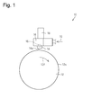
- FIG. 1 is a schematic view of an apparatus 10 for forming a continuous body.
- the device 10 includes a supply unit 16, a discharge unit 14, a cooling roll 12, and a valve 15.
- the resin material is supplied to the supply unit 16 as indicated by an arrow 19.
- the supply unit 16 has a built-in heater (not shown), and heats the supplied resin material to a molten state.
- the heated and melted resin may be supplied to the supply unit 16.
- the supply unit 16 pressurizes and supplies the heated and melted resin to the discharge unit 14.
- the discharge part 14 has a discharge port 14a, and discharges the resin supplied from the supply part 16 from the discharge port 14a.
- the rotatable cooling roll 12 is disposed below the discharge port 14a, and the molten resin discharged from the discharge port 14a is applied to the outer peripheral surface 12s of the cooling roll 12 rotating in the first direction indicated by the arrow 12f. It is configured to come into contact and be cooled.
- the cooling roll 12 is a cooling member, and has, for example, a flow path (not shown) in which a refrigerant circulates.
- an endless belt-shaped cooling member or the like may be used.
- the valve 15 can block the flow of the resin from the supply unit 16 to the discharge unit 14, and the solenoid 18 opens and closes the valve 15.
- the valve 15 When the valve 15 is used, the discharge of the resin from the discharge port 14a can be controlled with high accuracy, and therefore the connection of the continuous body before and after restarting described later becomes easy.
- a shutter mechanism including a shielding plate or the like may be used to control the discharge of the resin from the discharge port 14a.
- FIG. 2 is an explanatory diagram of the movement of the device 10.
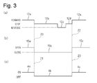
- FIG. 3 is a timing chart of the molding process and the post-process of the continuous body 2.
- 3A is a cooling roll 12
- FIG. 3B is a valve 15
- FIG. 3C is a timing chart of a post process.
- the cooling roll 12 rotates in the first direction (normal rotation) and the valve 15 is open.
- the resin discharged from the discharge port 14 a is brought into contact with the cooling roll 12 rotating in the first direction indicated by the arrow 12 f to cool the resin, whereby the continuous body is cooled.
- Mold 2 The formed continuous body 2 is supplied to a post-process line (not shown) as indicated by an arrow 2x.
- the post-process includes, for example, a process of laminating the molded continuous body 2 and another sheet.
- the resin material for molding the continuous body 2 contains a thermoplastic resin as a main component, and preferably has a thermoplastic elastic resin as a main component.
- a resin material containing a thermoplastic elastic resin as a main component such as elastic hot melt
- the continuous body 2 having elasticity can be molded, and connection of the continuous body before and after restarting described later becomes easy. ..
- the continuum 2 has a sheet shape, a film shape, a mesh shape according to the shape of the discharge port 14a, the amount of resin discharged from the discharge port 14a, the distance from the discharge port 14a to the cooling roll 12, the rotation speed of the cooling roll 12, and the like. It can be formed into various forms such as a strip shape, a strip shape of one or a plurality of strips, and a strip shape of a strip of one or a plurality of strips. For example, if the discharge port 14a is slit-shaped, the sheet-shaped, film-shaped, or strip-shaped continuous body 2 can be molded.
- a flow of air is formed in the space between the discharge port 14a and the cooling roll 12, and the flow of the resin moves the flow of the resin discharged from the discharge port 14a or divides the flow of the resin, and then the cooling is performed.
- the roll 12 cools, the mesh-like continuous body 2 can be formed.
- the rear end 2 a of the continuous body 2 stops at a position below the discharge port 14 a, that is, at the contact start position 13 at which the resin discharged from the discharge port 14 a starts contact with the cooling roll 12.
- the rear end 2a of the continuous body 2 may stop on the first direction side (the downstream side in the transport direction) with respect to the contact start position 13.
- the timing of stopping the line of the post-process, the timing of stopping the rotation of the cooling roll 12, and the timing of closing the valve 15 may be the same or may be the same. It doesn't matter. For example, when the continuum 2 does not expand or contract, or when the elasticity is small, the drive of the cooling roll 12, that is, the rotation of the cooling roll 12 is stopped and the valve 15 is closed with a slight delay from the stop of the line in the subsequent process. The slack may be generated in the continuum 2 after the first step.
- the sagging of the continuum 2 may occur after the first step as described above, or after the first step and before the second step.
- the tension adjusting mechanism of the continuous body 2 provided on the downstream side of the cooling roll 12 in the transport direction is operated to cause slack in the continuous body 2, the cooling roll 12 rotates in the second direction.
- the cooling roll 12 rotates in the first direction indicated by the arrow 12f, and the rear end 2a of the continuous body 2 formed before the restart is cooled. As the roll 12 rotates, it passes through the contact start position 13. When the resin immediately after the discharge from the discharge port 14a reaches the molded continuous body 2 before restarting until the rear end 2a of the continuous body 2 passes the contact start position 13, The continuous body formed after the operation and the continuous body 2 formed before the restart can be connected to each other.
- the continuum formed after the restart is connected to the continuum 2 formed before the restart so that the continuum 2 formed before the restart is supplied to the subsequent process. Therefore, the work of passing the continuum through the pass line before the re-operation becomes unnecessary, and the preparation before the re-operation can be completed in a short time without performing a troublesome work. Therefore, the work before re-operation can be reduced.
- the continuous body formed after the re-operation may be connected to the rear end 2a side of the continuous body 2 formed before the re-operation in a state of being overlapped with each other.
- a continuous body formed after restarting may be connected to the rear end 2a of the continuous body 2 thus formed.
- the mode in which the continuous body formed after the restart is connected to the continuous body 2 formed before the restart is the amount of rotation of the cooling roll 12 in the second direction and the timing at which the rotation of the cooling roll 12 is restarted. Alternatively, it can be adjusted depending on the timing at which the valve 15 opens. Therefore, the re-operation of the line in the post-process, the restart of the rotation of the cooling roll 12 in the first direction, and the opening of the valve 15 may be performed at the same time as indicated by broken lines 22 and 23 in FIG. You don't have to.
- the amount of rotation of the cooling roll 12 in the second direction in the second step is sufficiently large, and after the second step, from the rear end 2a of the continuous body 2 formed before the restart to the contact start position 13. Is sufficiently long and the distance from the discharge port 14a to the cooling roll 12 is short, restart of the line in the subsequent process, restart of rotation of the cooling roll 12, and switching of the valve 15 to "open". Even at the same time, the resin immediately after the ejection from the ejection port 14a is restarted can be connected to the continuous body 2 formed before the restart.
- the rotation amount of the cooling roll 12 in the second direction in the second step is small, and after the second step, the distance from the rear end 2a of the continuous body 2 formed before the restart to the contact start position 13 is short.
- the distance from the discharge port 14a to the cooling roll 12 is long, when the rotation of the cooling roll 12 is restarted after a lapse of a predetermined time after switching the valve 15 to "open", the discharge from the discharge port 14a is restarted.
- the resin immediately after can be connected to the continuous body 2 formed before the restart.
- a continuous body can be formed in the same manner as in Example 1 by using an apparatus provided with a cooling member such as an endless belt that circulates in a predetermined path instead of the rotating cooling roll 12.
- a cooling member such as an endless belt that circulates in a predetermined path instead of the rotating cooling roll 12.
- driving or the like for circulating the cooling member in the first direction is stopped, and in the second step, the cooling member is moved by a predetermined amount in a second direction opposite to the first direction.
- the driving of the cooling member is stopped, and in the third step, the driving of circulating the cooling member in the first direction is restarted, so that the resin immediately after the ejection is restarted is restarted. It can be connected to a molded continuum.
- the continuous body may be molded using a device other than the device described in the embodiment.
- a plurality of devices may be used to form a plurality of continuous bodies, and each continuous body may be supplied to the same post-process line.
Landscapes
- Engineering & Computer Science (AREA)
- Mechanical Engineering (AREA)
- Physics & Mathematics (AREA)
- Thermal Sciences (AREA)
- Manufacturing & Machinery (AREA)
- Extrusion Moulding Of Plastics Or The Like (AREA)
- Casting Or Compression Moulding Of Plastics Or The Like (AREA)
Abstract
再稼動前の作業を軽減することができる連続体の連続成形方法を提供する。 吐出口(14a)から吐出した樹脂を、第1の方向(12f)に駆動している冷却部材(12)に接触させて冷却することによって連続体(2)を成形し、成形された連続体(2)を後工程ラインに供給する。連続体(2)の後端(2a)側が、駆動を停止した冷却部材(12)上に残るように、後工程ラインと冷却部材(12)の駆動と樹脂の吐出とを停止する。次いで、冷却ロール(12)を第2の方向(12r)に駆動した後、駆動を停止して、連続体(2)の後端(2a)を、吐出された樹脂が冷却部材(12)との接触を開始する接触開始位置(13)よりも第2の方向(12r)側に移動させる。次いで、後工程ラインを再稼動し、冷却部材(12)の第1の方向(12f)の駆動と樹脂の吐出とを再開し、吐出が再開された直後の樹脂が、連続体(2)の後端(2a)側に接続されるようにする。
Description
本発明は、連続体の連続成形方法に関し、詳しくは、樹脂シート等の連続体の連続成形方法に関する。
樹脂シート等の連続体を成形する成形工程と、成形性した連続体を用いて積層シートを製造する後工程とを連続的に行うことが提案されている。図4は、連続体の成形工程及び後工程の略図である。
図4に示すように、連続体の成形工程では、熱可塑性弾性樹脂をTダイ111から押出成型して、溶融状態のフィルム状連続体103'を形成する。次いで、溶融状態のフィルム状連続体103'を冷却ロール120で冷却する。
後工程では、冷却されたフィルム状連続体103"を、2枚の連続した不織布102の間に挟み込んで積層体101'を形成し、エンボス処理を行う。エンボス処理は、その表面に多数のドット状の凸状部112aが形成されたエンボスロール112とバックアップロール113とで、積層体101'を加圧・挟持することにより行う。エンボス処理により各層が接合され一体化された積層シート101を、巻き取りロール116に巻き取る(例えば、特許文献1参照)。
上記のように、溶融状態の樹脂を冷却ロールに接触させて冷却することにより連続的に成形した連続体を、下流側の後工程のラインで連続的に加工する場合、後工程のラインを停止するとき、冷却ロールの回転を停止するとともに、溶融状態の樹脂の供給も停止する。
この状態から後工程のラインを再稼動するとともに、冷却ロールの回転や溶融状態の樹脂の供給を再開すると、連続体が途切れた状態になる。特に、樹脂の溶融粘度が低い場合、途切れやすい。
そのため、後工程のラインを再稼動する前に、連続体の成形のみを再開し、成形した連続体を、後工程において連続体が通るパスラインに通す作業が必要となる。
例えば、吸収性物品の製造ラインにおいて、樹脂シートの連続体を成形し、樹脂シートの連続体を弾性部材として用いる場合では、製造する製品のサイズ変更等でしばしばラインが停止することがあり、上記のような作業も多くなる。
かかる実情に鑑み、本発明が解決しようとする課題は、再稼動前の作業を軽減することができる連続体の連続成形方法を提供することである。
本発明は、上記課題を解決するために、以下のように構成した連続体の連続成形方法を提供する。
連続体の連続成形方法は、加熱されて溶融している樹脂を吐出口から吐出し、前記樹脂を、第1の方向に駆動している冷却部材に接触させて冷却することによって連続体を成形し、成形された前記連続体を後工程のラインに供給する。連続体の連続成形方法は,(i)前記連続体の後端側が、駆動を停止した前記冷却部材上に残るように、前記ラインを停止するとともに、前記冷却部材の駆動と前記吐出口からの前記樹脂の吐出とを停止する第1の工程と、(ii)前記第1の工程の後に、前記冷却部材を前記第1の方向とは反対の第2の方向に駆動した後、前記冷却部材の駆動を停止して、前記連続体の前記後端を、前記吐出口から吐出された前記樹脂が前記冷却部材との接触を開始する接触開始位置よりも前記第2の方向側に移動させる第2の工程と、(iii)前記第2の工程の後に、前記ラインを再稼動するとともに、前記冷却部材の前記第1の方向の駆動と前記吐出口からの前記樹脂の吐出とを再開して、前記吐出口からの吐出が再開された直後の前記樹脂が、前記連続体の前記後端側に接続されるようにする第3の工程と、を含む。
上記方法によれば、再稼動後に成形する連続体は、再稼動前に成形した連続体に続いて後工程に供給される。そのため、再稼動前に連続体をパスラインに通す作業が不要になり、面倒な作業をすることなく、短時間で再稼動前の準備を完了することができる。したがって、再稼動前の作業を、軽減することができる。
好ましくは、前記吐出口を有する吐出部と、前記吐出部に、加熱されて溶融している前記樹脂を加圧供給する供給部と、前記供給部から前記吐出部への前記樹脂の流れを遮断可能なバルブと、を備えた装置を用いる。前記第1の工程において、前記バルブを閉じて、前記吐出口からの前記樹脂の吐出を停止する。前記第3の工程において、前記バルブを開いて、前記吐出口からの前記樹脂の吐出を再開する。
この場合、吐出口からの樹脂の吐出を精度よく制御することができるので、再稼動前後の連続体の接続が容易になる。
好ましくは、前記樹脂は、熱可塑性弾性樹脂を主成分とする。
この場合、連続体は弾性部材であり、再稼動前の作業軽減効果が大きい。
本発明によれば、再稼動前の作業を軽減することができる。
以下、本発明の実施の形態について、図面を参照しながら説明する。
<実施例1> 実施例1の連続体の連続成形方法について、図1~図3を参照しながら説明する。
図1は、連続体を成形する装置10の略図である。図1に示すように、装置10は、供給部16と、吐出部14と、冷却ロール12と、バルブ15とを備える。
供給部16は、矢印19で示すように、樹脂材料が供給される。供給部16は、不図示のヒータを内蔵しており、供給された樹脂材料を加熱して溶融状態にする。供給部16に、加熱されて溶融している樹脂が供給されても構わない。供給部16は、加熱されて溶融している樹脂を、吐出部14に加圧供給する。吐出部14は、吐出口14aを有し、供給部16から供給された樹脂を吐出口14aから吐出する。
吐出口14aの下方に、回転可能な冷却ロール12が配置され、吐出口14aから吐出した溶融状態の樹脂が、矢印12fで示す第1の方向に回転している冷却ロール12の外周面12sに接触して冷却されるように構成されている。冷却ロール12は冷却部材であり、例えば、内部に冷媒が循環する不図示の流路が設けられている。冷却ロール12に代えて、無端ベルト状等の冷却部材を用いても構わない。
バルブ15は、供給部16から吐出部14への樹脂の流れを遮断可能であり、ソレノイド18によってバルブ15が開閉する。バルブ15を用いると、吐出口14aからの樹脂の吐出を精度よく制御することできるので、後述する再稼動前後の連続体の接続が容易になる。バルブ15以外、例えば、遮蔽板を含むシャッター機構等を用いて、吐出口14aからの樹脂の吐出を制御してもよい。
次に、装置10を用いて連続体2を成形する方法、すなわち、連続体の連続成形方法について、図2及び図3を参照しながら説明する。図2は、装置10の動きの説明図である。図3は、連続体2の成形工程及び後工程のタイミングチャートある。図3(a)は冷却ロール12、図3(b)はバルブ15、図3(c)は後工程のタイミングチャートである。
図3において符号4a,12a,15aで示すように、後工程のラインが稼動しているとき、冷却ロール12は第1の方向に回転(正転)し、バルブ15は開いている。このとき、図2(a)に示すように、吐出口14aから吐出された樹脂を、矢印12fで示す第1の方向に回転している冷却ロール12に接触させて冷却することによって、連続体2を成形する。成形した連続体2は、矢印2xで示すように、不図示の後工程のラインに供給する。後工程は、例えば、成形した連続体2と他のシートとを積層する工程を含む。
連続体2を成形するための樹脂材料は、熱可塑性樹脂を主成分し、好ましくは、熱可塑性弾性樹脂を主成分とする。例えば、弾性ホットメルトのように、熱可塑性弾性樹脂を主成分する樹脂材料を用いると、弾性を有する連続体2を成形することができ、後述する再稼動前後の連続体の接続が容易になる。
連続体2は、吐出口14aの形状、吐出口14aからの樹脂の吐出量、吐出口14aから冷却ロール12までの距離、冷却ロール12の回転速度等に応じて、シート状、フィルム状、網目状、1本又は複数本の帯状、1本又は複数本の紐状など、種々の態様に成形することができる。例えば、吐出口14aがスリット状であれば、シート状や、フィルム状や、帯状の連続体2を成形することができる。吐出口14aと冷却ロール12との間の空間に空気の流れを形成し、この空気の流れで、吐出口14aから吐出した樹脂の流れを動かしたり、樹脂の流れを分断したりした後に、冷却ロール12で冷却すると、網目状の連続体2を成形することができる。
後工程のラインにおいて製品の品種変更等を行う場合等には、一旦、稼動を停止した後に、再稼動する。その際の手順は、次のとおりである。
(1)まず、図3において符号4b,12b,15bで示すように、後工程のラインを停止するとともに、冷却ロール12の駆動、すなわち冷却ロール12の回転を停止し、バルブ15を閉じて、吐出口14aからの樹脂の吐出を停止する。このとき、図2(b)に示すように、連続体2の後端2a側が、回転を停止した冷却ロール12上に残るようにする。これは、第1の工程である。
図2(b)では、連続体2の後端2aが吐出口14aの下の位置、すなわち、吐出口14aから吐出された樹脂が冷却ロール12との接触を開始する接触開始位置13に停止しているが、連続体2の後端2aが、接触開始位置13よりも第1の方向側(搬送方向下流側)で停止してもよい。
図3において破線20,21で示すように、後工程のラインが停止するタイミングと、冷却ロール12の回転が停止するタイミングと、バルブ15が閉になるタイミングとが同時であっても、同時でなくても構わない。例えば、連続体2が伸縮しない場合や、伸縮性が小さい場合、後工程のラインの停止から若干遅れて、冷却ロール12の駆動、すなわち冷却ロール12の回転を停止するとともにバルブ15を閉にして、第1の工程後に連続体2にたるみが生じるようにしてもよい。
(2)次いで、すなわち第1の工程の後に、図3において符号12cで示すように、冷却ロール12を第1の方向とは反対の第2の方向に駆動して回転(逆転)させた後、符号12dで示すように、冷却ロール12の駆動を停止して、図2(c)に示すように、連続体2の後端2aを、接触開始位置13よりも第2の方向側(搬送方向上流側)に移動させる。これは、第2の工程である。
第1の工程後に、連続体2の後端2aが、接触開始位置13よりも第1の方向側(搬送方向下流側)で停止している場合、連続体2の後端2aが接触開始位置13を通過するように、冷却ロール12は、矢印12rで示す第2の方向に回転する。
第2の工程において、冷却ロール12の第2の方向の回転に伴って連続体2が引っ張られても、連続体2が破断しないようにする。
連続体2が伸縮しない場合や、伸縮性が小さい場合、前述したように第1の工程後に連続体2にたるみが生じるようにしたり、第1の工程の後、かつ、第2の工程の前に、冷却ロール12よりも搬送方向下流側に設けた連続体2の張力調整機構等を操作して、連続体2にたるみが生じるようにしたりすると、冷却ロール12が第2の方向に回転しても、連続体2が破断しないようにすることができる。
伸縮性が大きい連続体2の場合は、冷却ロール12が第2の方向に回転しても、連続体2が破断することなく伸びるようにすることが容易である。
(3)次いで、すなわち第2の工程の後に、図3において符号4c,12e,15cで示すように、後工程のラインを再稼動するとともに、冷却ロール12の第1の方向の駆動、すなわち回転(正転)を再開し、バルブ15を開いて吐出口14aからの樹脂の吐出を再開して、吐出口14aからの吐出が再開された直後の樹脂が、連続体2の後端2a側に接続されるようにする。これは第3の工程である。
第3の工程において、図2(d)に示すように、冷却ロール12は、矢印12fで示す第1の方向に回転し、再稼動前に成形された連続体2の後端2aは、冷却ロール12の回転に伴って、接触開始位置13を通過する。連続体2の後端2aが接触開始位置13を通過するまでの間に、吐出口14aからの吐出が再開された直後の樹脂が、再稼動前に成形された連続体2に達すると、再稼動後に成形される連続体と、再稼動前に成形された連続体2とが互いに接続されるようにすることができる。
再稼動後に成形される連続体は、再稼動前に成形された連続体2に接続されることによって、再稼動前に成形された連続体2に続いて後工程に供給される。そのため、再稼動前に連続体をパスラインに通す作業が不要になり、面倒な作業をすることなく、短時間で再稼動前の準備を完了することができる。したがって、再稼動前の作業を、軽減することができる。
再稼動後に成形される連続体は、再稼動前に成形された連続体2の後端2a側に重なる状態で接続されてもよいし、重なりが生じないように、すなわち、再稼動前に成形された連続体2の後端2aに、再稼動後に成形される連続体が接続されてもよい。
再稼動後に成形される連続体と、再稼動前に成形された連続体2とが接続される態様は、冷却ロール12の第2の方向の回転量や、冷却ロール12の回転を再開するタイミングや、バルブ15が開になるタイミング等によって調整することができる。そのため、後工程のラインの再稼動と、冷却ロール12の第1の方向の回転の再開と、バルブ15の開とは、図3において破線22,23で示すように同時でもよいし、同時でなくてもよい。
例えば、第2の工程における冷却ロール12の第2の方向の回転量が十分に大きく、第2の工程後において、再稼動前に成形された連続体2の後端2aから接触開始位置13までの距離が十分に長く、吐出口14aから冷却ロール12までの距離が短い場合、後工程のラインの再稼動と、冷却ロール12の回転の再開と、バルブ15の「開」への切り替えとが同時でも、吐出口14aからの吐出が再開された直後の樹脂を、再稼動前に成形された連続体2に接続することができる。
第2の工程における冷却ロール12の第2の方向の回転量が少なく、第2の工程後において、再稼動前に成形された連続体2の後端2aから接触開始位置13までの距離が短く、吐出口14aから冷却ロール12までの距離が長い場合、バルブ15を「開」に切り替えてから所定時間が経過した後に冷却ロール12の回転を再開すると、吐出口14aからの吐出が再開された直後の樹脂を、再稼動前に成形された連続体2に接続することができる。
<変形例1> 回転する冷却ロール12ではなく、所定経路を循環する無端ベルト状等の冷却部材を備えた装置を用いても、実施例1と同様に、連続体を成形することができる。その場合、第1の工程では、冷却部材を第1の方向に循環させる駆動等を停止し、第2の工程では、冷却部材を、第1の方向とは反対の第2の方向に所定量駆動した後、冷却部材の駆動を停止し、第3の工程では、冷却部材を第1の方向に循環させる駆動等を再開することによって、吐出が再開された直後の樹脂を、再稼動前に成形された連続体に接続することができる。
<まとめ> 以上に説明したように、再稼動後に成形される連続体が、再稼動前に成形された連続体に接続されるようにすることによって、再稼動前の作業を軽減することができる。
なお、本発明は、上記実施の形態に限定されるものではなく、種々変更を加えて実施することが可能である。
例えば、実施例で説明した装置以外を用いて、連続体を成形してもよい。また、複数台の装置を用いて複数の連続体を成形し、それぞれの連続体を同じ後工程のラインに供給してもよい。
2 連続体
2a 後端
10 装置
12 冷却ロール(冷却部材)
12f 第1の方向
12r 第2の方向
13 接触開始位置
14 吐出部
14a 吐出口
15 バルブ
16 供給部
2a 後端
10 装置
12 冷却ロール(冷却部材)
12f 第1の方向
12r 第2の方向
13 接触開始位置
14 吐出部
14a 吐出口
15 バルブ
16 供給部
Claims (3)
- 加熱されて溶融している樹脂を吐出口から吐出し、前記樹脂を、第1の方向に駆動している冷却部材に接触させて冷却することによって連続体を成形し、成形された前記連続体を後工程のラインに供給する連続体の連続成形方法であって、
前記連続体の後端側が、駆動を停止した前記冷却部材上に残るように、前記ラインを停止するとともに、前記冷却部材の駆動と前記吐出口からの前記樹脂の吐出とを停止する第1の工程と、
前記第1の工程の後に、前記冷却部材を前記第1の方向とは反対の第2の方向に駆動した後、前記冷却部材の駆動を停止して、前記連続体の前記後端を、前記吐出口から吐出された前記樹脂が前記冷却部材との接触を開始する接触開始位置よりも前記第2の方向側に移動させる第2の工程と、
前記第2の工程の後に、前記ラインを再稼動するとともに、前記冷却部材の前記第1の方向の駆動と前記吐出口からの前記樹脂の吐出とを再開して、前記吐出口からの吐出が再開された直後の前記樹脂が、前記連続体の前記後端側に接続されるようにする第3の工程と、
を含むことを特徴とする、連続体の連続成形方法。 - 前記吐出口を有する吐出部と、
前記吐出部に、加熱されて溶融している前記樹脂を加圧供給する供給部と、
前記供給部から前記吐出部への前記樹脂の流れを遮断可能なバルブと、
を備えた装置を用い、
前記第1の工程において、前記バルブを閉じて、前記吐出口からの前記樹脂の吐出を停止し、
前記第3の工程において、前記バルブを開いて、前記吐出口からの前記樹脂の吐出を再開することを特徴とする、請求項1に記載の連続体の連続成形方法。 - 前記樹脂は、熱可塑性弾性樹脂を主成分とすることを特徴とする、請求項1又は2に記載の連続体の連続成形方法。
Priority Applications (2)
| Application Number | Priority Date | Filing Date | Title |
|---|---|---|---|
| JP2020555691A JPWO2020100836A1 (ja) | 2018-11-13 | 2019-11-11 | 連続体の連続成形方法 |
| CN201980070511.1A CN112912226B (zh) | 2018-11-13 | 2019-11-11 | 连续体的连续成型方法 |
Applications Claiming Priority (2)
| Application Number | Priority Date | Filing Date | Title |
|---|---|---|---|
| JP2018-212750 | 2018-11-13 | ||
| JP2018212750 | 2018-11-13 |
Publications (1)
| Publication Number | Publication Date |
|---|---|
| WO2020100836A1 true WO2020100836A1 (ja) | 2020-05-22 |
Family
ID=70731089
Family Applications (1)
| Application Number | Title | Priority Date | Filing Date |
|---|---|---|---|
| PCT/JP2019/044200 Ceased WO2020100836A1 (ja) | 2018-11-13 | 2019-11-11 | 連続体の連続成形方法 |
Country Status (3)
| Country | Link |
|---|---|
| JP (1) | JPWO2020100836A1 (ja) |
| CN (1) | CN112912226B (ja) |
| WO (1) | WO2020100836A1 (ja) |
Citations (2)
| Publication number | Priority date | Publication date | Assignee | Title |
|---|---|---|---|---|
| JPH03234611A (ja) * | 1990-02-13 | 1991-10-18 | Aisin Seiki Co Ltd | 樹脂モール押出し成形方法 |
| JPH1029259A (ja) * | 1996-07-17 | 1998-02-03 | Kao Corp | 積層シートおよびその製造方法 |
Family Cites Families (7)
| Publication number | Priority date | Publication date | Assignee | Title |
|---|---|---|---|---|
| JPH0673901B2 (ja) * | 1986-03-05 | 1994-09-21 | 三菱重工業株式会社 | 熱可塑性樹脂シートの冷却成形装置 |
| DE10152843A1 (de) * | 2000-11-29 | 2002-06-13 | Heidelberger Druckmasch Ag | Vorrichtung zur Anpassung der Lage bogenförmigen Material bei Bewegungsrichtungsumkehr |
| CN201712158U (zh) * | 2010-07-21 | 2011-01-19 | 宁波市派特勒粉末涂料有限公司 | 挤出机急停开关装置 |
| US9855682B2 (en) * | 2011-06-10 | 2018-01-02 | Columbia Insurance Company | Methods of recycling synthetic turf, methods of using reclaimed synthetic turf, and products comprising same |
| JP2011218814A (ja) * | 2011-06-21 | 2011-11-04 | Fujifilm Corp | 熱可塑性フィルムの製造方法 |
| JP5874211B2 (ja) * | 2011-06-23 | 2016-03-02 | 大日本印刷株式会社 | 積層体製造装置 |
| US20140264979A1 (en) * | 2013-03-13 | 2014-09-18 | Transitions Opticals, Inc. | Method of preparing photochromic-dichroic films having reduced optical distortion |
-
2019
- 2019-11-11 JP JP2020555691A patent/JPWO2020100836A1/ja not_active Ceased
- 2019-11-11 WO PCT/JP2019/044200 patent/WO2020100836A1/ja not_active Ceased
- 2019-11-11 CN CN201980070511.1A patent/CN112912226B/zh not_active Expired - Fee Related
Patent Citations (2)
| Publication number | Priority date | Publication date | Assignee | Title |
|---|---|---|---|---|
| JPH03234611A (ja) * | 1990-02-13 | 1991-10-18 | Aisin Seiki Co Ltd | 樹脂モール押出し成形方法 |
| JPH1029259A (ja) * | 1996-07-17 | 1998-02-03 | Kao Corp | 積層シートおよびその製造方法 |
Also Published As
| Publication number | Publication date |
|---|---|
| CN112912226B (zh) | 2022-11-29 |
| JPWO2020100836A1 (ja) | 2021-09-27 |
| CN112912226A (zh) | 2021-06-04 |
Similar Documents
| Publication | Publication Date | Title |
|---|---|---|
| US8980030B2 (en) | Method and apparatus for forming a multi-layered tire component | |
| RU2009134723A (ru) | Способ и установка для нанесения пленочного материала на последовательно перемещаемые листы | |
| CN110049856B (zh) | 纵向拉伸装置 | |
| US10214377B2 (en) | Sheet processing apparatus | |
| JP2009082962A (ja) | 小片シートの製造方法 | |
| TWI236965B (en) | Film adhering method and device | |
| CN101410241A (zh) | 层压设备 | |
| CN101274485B (zh) | 拉伸聚合物膜的方法和用于回收切割膜边缘的设备 | |
| WO2020100836A1 (ja) | 連続体の連続成形方法 | |
| CN109152667B (zh) | 吸收性物品的制造方法 | |
| CN104191634A (zh) | 挤出式宽幅膜材、片材生产线 | |
| JP6178152B2 (ja) | 熱成形装置 | |
| JP2911870B2 (ja) | フィルム製造設備から溶融フィルムを連続的に引取るための方法及び装置 | |
| JP2014162111A (ja) | パターン転写用金型とこれを用いたパターン転写装置 | |
| JP7786717B2 (ja) | ラミネートシステム、フィルム貼合カット装置、ラミネート方法、及びラミネート形成物の製造方法 | |
| JP7203118B2 (ja) | 積層体の製造方法および製造装置 | |
| JP7256998B2 (ja) | 積層体の製造方法および製造装置 | |
| JP2016176986A5 (ja) | ||
| JP7337834B2 (ja) | 熱可塑性フィルムの生成方法および生成装置 | |
| JP2016008110A (ja) | 用紙搬送装置 | |
| KR100446095B1 (ko) | 원단 합포장치 | |
| CN106029340A (zh) | 拉伸膜的制造方法 | |
| JP2019118451A (ja) | 吸収性物品の製造方法及び吸収性物品製造装置 | |
| JPH06278356A (ja) | 転写方法及びその転写装置 | |
| JP2025105059A (ja) | ボンディング装置 |
Legal Events
| Date | Code | Title | Description |
|---|---|---|---|
| 121 | Ep: the epo has been informed by wipo that ep was designated in this application |
Ref document number: 19884104 Country of ref document: EP Kind code of ref document: A1 |
|
| ENP | Entry into the national phase |
Ref document number: 2020555691 Country of ref document: JP Kind code of ref document: A |
|
| NENP | Non-entry into the national phase |
Ref country code: DE |
|
| 122 | Ep: pct application non-entry in european phase |
Ref document number: 19884104 Country of ref document: EP Kind code of ref document: A1 |