WO2020100576A1 - 近接センサ - Google Patents
近接センサ Download PDFInfo
- Publication number
- WO2020100576A1 WO2020100576A1 PCT/JP2019/042354 JP2019042354W WO2020100576A1 WO 2020100576 A1 WO2020100576 A1 WO 2020100576A1 JP 2019042354 W JP2019042354 W JP 2019042354W WO 2020100576 A1 WO2020100576 A1 WO 2020100576A1
- Authority
- WO
- WIPO (PCT)
- Prior art keywords
- clamp
- rib
- sealing ring
- resin
- cable
- Prior art date
- Legal status (The legal status is an assumption and is not a legal conclusion. Google has not performed a legal analysis and makes no representation as to the accuracy of the status listed.)
- Ceased
Links
Images

Classifications
-
- H—ELECTRICITY
- H01—ELECTRIC ELEMENTS
- H01H—ELECTRIC SWITCHES; RELAYS; SELECTORS; EMERGENCY PROTECTIVE DEVICES
- H01H36/00—Switches actuated by change of magnetic field or of electric field, e.g. by change of relative position of magnet and switch, by shielding
-
- H—ELECTRICITY
- H01—ELECTRIC ELEMENTS
- H01H—ELECTRIC SWITCHES; RELAYS; SELECTORS; EMERGENCY PROTECTIVE DEVICES
- H01H9/00—Details of switching devices, not covered by groups H01H1/00 - H01H7/00
- H01H9/02—Bases, casings, or covers
- H01H9/04—Dustproof, splashproof, drip-proof, waterproof, or flameproof casings
-
- H—ELECTRICITY
- H01—ELECTRIC ELEMENTS
- H01H—ELECTRIC SWITCHES; RELAYS; SELECTORS; EMERGENCY PROTECTIVE DEVICES
- H01H9/00—Details of switching devices, not covered by groups H01H1/00 - H01H7/00
- H01H9/16—Indicators for switching condition, e.g. "on" or "off"
Definitions
- the present invention relates to a proximity sensor.
- the proximity sensor includes a housing that houses electronic components and a clamp.
- a cable is inserted into the clamp through an opening provided in the clamp. The cable is electrically connected to the electronic component.
- Patent Document 1 discloses a closed structure of a proximity sensor in which a packing (corresponding to an O ring) is provided between a case and a cable.
- an object of the present invention is to provide a proximity sensor with high sealing property.
- a proximity sensor includes a tubular housing having an opening formed at one end, an electronic component housed in the housing, and a tubular shape having one end inserted into the housing through the opening.
- the clamp the cable inserted into the clamp from the other end of the clamp and connected to the electronic component, the sealing ring that surrounds the cable and seals the gap between the clamp and the cable, and is provided inside the clamp.
- the sealing ring has a rib portion that is raised so as to come into contact with the inner wall of the clamp, and the rib portions are formed side by side in a direction along the central axis of the sealing ring.
- the rib located on the resin side (front side of the sensor) can prevent the resin from leaking out of the sensor. Even if resin adheres to the rib located on the resin side, resin does not adhere to the rib located on the rear side of the sensor and the rib located on the rear side remains elastic. Is. Therefore, the sealing ring can prevent liquid or dust from entering the inside of the sensor through the gap between the cable and the clamp by the rear rib portion.
- the rib portion may be formed in an annular shape along the outer peripheral direction of the sealing ring.
- the rib portion may have two rib side walls standing from the outer peripheral surface of the sealing ring, and the surfaces of the two rib side walls may intersect at the top of the rib portion.
- the sealing ring can be easily housed inside the clamp.
- the rib portion may have two rib sidewalls that stand upright from the outer peripheral surface of the sealing ring, and a connecting surface that connects the surfaces of the two rib sidewalls at the top of the rib portion.
- the rib portion and the inner wall of the clamp are more appropriately brought into close contact with each other. Therefore, the sealing quality in mass production of the sensor can be homogenized.
- three or more rib portions may be formed side by side in the direction along the central axis of the sealing ring.
- the sealing quality in mass production of the sensor can be homogenized.
- the sealing ring may be formed of an elastic material.
- the sealing ring properly contacts the inner wall of the clamp and the outer peripheral surface of the cable.
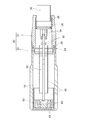
- FIG. 2 is a cross-sectional view taken along the line II-II in the assembled state of the sensor shown in FIG. 1.
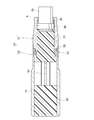
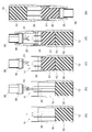
- FIG. 3 is a diagram showing a state in which a sealing resin is provided inside the sensor shown in FIG. 2. It is a figure which shows the process of providing sealing resin inside a sensor.
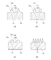
- FIG. 4 is an enlarged view of a broken line area A shown in FIG. 3. It is a figure which shows the variation of the rib part which a sealing ring has.
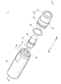
- FIG. 1 is an exploded perspective view of a sensor 1 according to an embodiment of the present invention.
- FIG. 2 is a cross-sectional view taken along the line II-II in the assembled state of the sensor 1 shown in FIG.
- the sensor 1 is a proximity sensor that can detect that a detection target approaches without contact, and includes the housing 10, the clamp 20, the O ring 25, the substrate 30, the cable strand 34, the cable 35, and the ring.
- the component 36, the detector 40, and the shield 45 are provided.
- the housing 10 is formed in a tubular shape, and accommodates electronic components such as the substrate 30 inside.
- the housing 10 has an opening 11 at one end, and electronic components such as the substrate 30 are inserted through the opening 11.
- the housing 10 may be made of metal, resin, or the like.
- the sensor 1 has a cylindrical outer shape, but may have a prismatic shape in which the outer circumferences of the housing 10 and the clamp 20 are polygonal.
- the end of the clamp 20 is connected to the opening 11 of the housing 10, and protects electronic components such as the substrate 30 housed in the housing 10.
- the front portion of the clamp 20 is inserted into the housing 10 through the opening 11.
- a large area of the board 30 is housed in the housing 10, but a rear area of the board 30 is housed in the clamp 20.
- the clamp 20 accommodates a part of the cable strand 34, the ring component 36, and the cable 35.
- the clamp 20 includes a tubular first part 21 and a second part 22. Specifically, the front end of the first component 21 is fitted inside the second component 22.
- the clamp 20 has a recess 24 between the first component 21 and the second component 22, and an O-ring 25 is attached to the recess 24. As shown in FIG. 2, the O-ring 25 is located inside the housing 10 in a state where the sensor 1 is assembled, and seals a gap between the inner wall of the housing 10 and the outer wall of the clamp 20.
- the clamp 20 (the first component 21 and the second component 22) can be formed of resin, metal, or the like, but is formed of a transparent material that transmits visible light, and the indicator lamp 32 positioned inside the sensor 1 is It is preferably visible from the outside.
- the board 30 is a board on which a control circuit (not shown) that controls the detection unit 40 and a current supply circuit (not shown) that supplies a current to the detection unit 40 are mounted, and a part of the housing 10 is housed.
- the detection unit 40 is attached to the front end of the substrate 30.
- the detection unit 40 detects the presence or absence of a detection target in a non-contact manner.
- the detection unit 40 includes a core 41 that accommodates the coil 42, and a coil 42 that is wound in an annular shape.
- a land 31 is provided on the rear end of the substrate 30, and is electrically connected to the cable strand 34.
- an exciting current is supplied to the coil 42 from the current supply circuit mounted on the substrate 30.
- the coil 42 generates a magnetic field based on the supplied exciting current.
- a detection target such as a metal approaches the coil 42 in this state
- an eddy current is generated inside the detection target according to the law of electromagnetic induction. Since this eddy current generates a magnetic field, the magnetic flux penetrating the coil 42, and consequently the impedance of the coil 42, changes.
- the control circuit connected to the detection unit 40 measures the change in the impedance of the coil 42 and detects the presence or absence of the detection target.
- the board 30 is equipped with an indicator light 32 for displaying the operating state of the sensor 1.
- the indicator light 32 may be, for example, an LED or the like. In the present embodiment, the indicator light 32 lights up when the sensor 1 is powered on or when the sensor 1 detects a detection target.
- the cable 35 is formed by applying a protective coating to a plurality of cable strands 34.
- the cable strand 34 is electrically connected to the land 31 of the substrate 30.
- the cable strand 34 may supply the electric power from the external power supply to the circuit mounted on the substrate 30. Further, the cable strand 34 may transmit the output signal from the control circuit mounted on the substrate 30 to an external device such as an amplifier.
- the ring component 36 is provided on the outer circumference of the cable 35, and is mainly responsible for centering the cable 35 and positioning the sealing ring.
- the ring component 36 may have a shape that covers only the outer periphery of the protective coating. Further, the ring component 36 may have a shape that covers the end of the protective coating of the cable 35. Since the ring component 36 has a shape that covers the end of the protective coating, it is possible to secure a large adhesiveness with the sealing resin filled inside the sensor 1 and a large adhesive creepage surface, and the thermal shock resistance performance and oil resistance performance of the sensor 1. Is improved. Further, the ring component 36 is in close contact with the sealing resin with which the inside of the housing 10 is filled, and fixes the cable 35 to the clamp 20.
- a sealing ring 38 is provided in a region between the cable 35 and the first component 21 and behind the ring component 36 so as to surround the cable 35.
- the sealing ring 38 seals the gap between the inner wall of the clamp 20 and the outer periphery of the cable 35.
- the sealing ring 38 prevents liquid or dust from entering from the outside of the sensor 1.
- the sealing ring 38 prevents the sealing resin with which the inside of the sensor 1 is filled from leaking to the outside.
- Shield 45 removes noise from the outside.
- the shield 45 is provided so as to surround a part of the detection unit 40 and the substrate 30, and prevents noise from reaching the detection unit 40 and the substrate 30.
- the shield 45 may be formed of, for example, a metal film or a laminated member of copper foil and polyimide resin.
- FIG. 3 is a diagram showing a state in which a sealing resin (first resin 50 and second resin 51) is provided inside the sensor 1 shown in FIG.
- FIG. 4 is a diagram showing a step of providing a sealing resin inside the sensor 1.
- the first resin 50 of the sealing resin is provided in the front region inside the housing 10 as shown in FIG. 3, and covers a part of the detection unit 40 and the substrate 30.
- the first resin 50 fixes the substrate 30 to the housing 10 and prevents the substrate 30 from being displaced.
- the second resin 51 is provided in the rear region inside the housing 10 and inside the clamp 20.
- the second resin 51 seals the gap between the housing 10 and the clamp 20.
- a void in which no resin exists is provided between the first resin 50 and the second resin 51.
- FIG. 4A A process of providing the first resin 50 and the second resin 51 inside the housing 10 will be described with reference to FIG.
- the housing 10 is arranged so that the front surface 12 is located on the lower side, and the first resin 50 in a liquid state is poured into the housing 10 through the opening 11.
- the substrate 30 to which the detection unit 40 and the shield 45 are attached is inserted into the housing 10. In this state, the first resin 50 is solidified and the substrate 30 is fixed to the housing 10.
- the cable wire 34 is connected to the land of the board 30.
- the connection between the cable wire 34 and the land may be performed by soldering.
- the second resin 51 is poured into the housing 10 through the opening 11.
- the clamp 20 is inserted into the opening 11 of the housing 10. Then, before the second resin 51 is solidified, the entire sensor 1 is turned upside down as shown in FIG. Then, the second resin 51 moves to the clamp 20 side due to the influence of gravity, and a space is provided between the first resin 50 and the second resin 51. In this state, the second resin 51 is solidified.
- the sealing resin is provided inside the housing 10 by the above method. The method is not limited to the above-described method, and the sealing resin is provided inside the sensor 1 by a method in which a minute hole is provided in the housing 10 or the clamp 20 and the inside of the sensor 1 is filled with the sealing resin. Good.
- the second resin 51 is poured into the sensor 1 in the liquid state. Therefore, when the second resin 51 is provided inside the sensor 1, the liquid second resin 51 may reach the rear end portion of the clamp 20. Specifically, the second resin 51 passes through the gap between the ring component 36 and the clamp 20 and reaches the sealing ring 38.
- the sealing ring 38 impedes the flow of the second resin 51 and prevents the second resin 51 from leaking out of the sensor 1 through the gap between the clamp 20 and the cable 35.
- the sealing ring 38 will be described with reference to FIG.
- FIG. 5 is an enlarged view of the broken line area A shown in FIG. 3, and is a view showing an example of the cross-sectional shape of the sealing ring 38.
- the ring component 36 is not shown for the sake of explanation.
- the sensor to which the present invention is applied may be a sensor that does not include the ring component 36.
- the sealing ring 38 is provided so as to surround the cable 35 and is located between the outer peripheral surface 35 a of the cable 35 and the inner wall 20 a of the clamp 20.
- the sealing ring 38 has, on its outer peripheral surface 38a, two rib portions 60 and 61 that are raised so as to come into contact with the inner wall 20a of the clamp 20.
- the rib portion 60 located on the front side of the sensor 1 has a top portion 60a and two rib side walls 60b and 60c.
- the surface of the rib side wall 60b is an inclined surface that descends from the top portion 60a to the front side of the sensor 1.
- the surface of the rib side wall 60c is an inclined surface that descends from the top 60a toward the rear side of the sensor 1.
- the rib portion 61 located on the rear side of the sensor 1 includes a top portion 61a and rib side walls 61b and 61c.
- the top portion 61a and the rib side walls 61b and 61c of the rib portion 61 have the same configurations as the top portion 60a and the rib side walls 60b and 60c of the rib portion 60, respectively.
- the sealing ring 38 is made of an elastic material.
- the sealing ring 38 may be formed of a resin such as fluororubber. Since the sealing ring 38 is formed of an elastic material, the top portion 60a of the rib portion 60 is in close contact with the inner wall 20a of the clamp 20, and the inner peripheral surface 38b of the sealing ring 38 is in close contact with the outer peripheral surface 35a of the cable 35. is doing.
- the second resin 51 in the liquid state poured into the sensor 1 moves between the cable 35 and the clamp 20 in the direction of the arrow shown in FIG. Specifically, the second resin 51 moves from the front side of the sensor 1 toward the sealing ring 38.
- the sealing ring 38 is in close contact with the cable 35 and the clamp 20 as described above, and seals the gap between the cable 35 and the clamp 20. Therefore, the second resin 51 is stopped by the sealing ring 38.
- the second resin 51 does not adhere to the rib portion 61 or the rear side surface 39b of the sealing ring 38. Further, the rib portion 60 and the rib portion 61 are located apart from each other. Therefore, even if the second resin 51 adheres to the rib side wall 60b of the rib portion 60, the front side surface 39a of the sealing ring 38, and the like, and the elasticity of the front portion of the sealing ring 38 is lost, the rib portion is lost.
- the rear portion of the sealing ring 38, including 61 remains elastic.
- the top 61a of the rib portion 61 is in close contact with the inner wall 20a of the clamp 20, and at least the region of the inner peripheral surface 38b of the sealing ring 38 located on the rear side is in close contact with the outer peripheral surface 35a of the cable 35.
- the rib portion 60 located on the front side (the second resin 51 side) of the sensor 1 allows the second resin 51 to be formed. Can be prevented from leaking out of the sensor 1. Further, even when the second resin 51 is attached to the rib portion 60 located on the second resin 51 side, the second resin 51 does not attach to the rib portion 61 located on the rear side of the sensor 1 and the rear portion The rib portion 61 located on the side remains elastic. Therefore, the sealing ring 38 can prevent liquid or dust from entering the inside of the sensor through the gap between the cable 35 and the clamp 20 by the rib portion 61 on the rear side.
- FIG. 6A is a diagram showing an example of the shape of the rib portion.
- the rib portion 70 shown in FIG. 6 (a) has a top portion 70 a that abuts the inner wall 20 a of the clamp 20, and two rib side walls 70 b and 70 c that stand upright from the outer peripheral surface 38 a of the sealing ring 38.
- the surface of the rib side wall 70b and the surface of the rib side wall 70c intersect at the top portion 70a. That is, in the cross-sectional view shown in FIG. 6A, the top portion 70a of the rib portion 70 has a pointed shape.
- the rib portion 70 since the contact area between the inner wall 20a of the clamp 20 and the rib portion 70 is small, when the sealing ring 38 is housed in the clamp 20, the rib portion 70 and the rib portion 70 are separated from each other. The frictional force generated between is small. Therefore, the sealing ring 38 can be easily accommodated inside the clamp 20.
- the rib portion 71 shown in FIG. 6 (b) has a top portion 71 a that comes into contact with the inner wall 20 a of the clamp 20, and two rib side walls 71 b and c that stand from the outer peripheral surface 38 a of the sealing ring 38.
- the top portion 71a is a connection surface that connects the surface of the rib side wall 70b and the surface of the rib side wall 70c.
- the rib portion 71 has a trapezoidal shape.
- the top portion 71a is in surface contact with the inner wall 20a of the clamp 20 when the sensor 1 is assembled.
- the top portion 71a of the rib portion 71 is in surface contact with the inner wall 20a of the clamp 20, so that the rib portion 71 and the inner wall 20a of the clamp 20 are more appropriately brought into close contact with each other. Therefore, the sealing quality in mass production of the sensor 1 can be made uniform.
- the rib portion 72 shown in FIG. 6C has a top portion 72a that abuts the inner wall 20a of the clamp 20, and two rib sidewalls 72b and 72c that stand upright from the outer peripheral surface 38a of the sealing ring 38.
- the surface of the rib side wall 72b and the surface of the rib side wall 72c are curved so as to be closer to each other toward the apex 72a, and are smoothly connected at the apex 72a. That is, the rib portion 72 has a dome shape in the cross-sectional view shown in FIG. According to the rib portion 72 according to this aspect, since the rib portion 72 does not have a corner portion protruding outward, a defect such as a breakage of the corner portion does not occur at the time of manufacturing the sealing ring 38.
- the rib portions 73 shown in FIG. 6 (d) are formed side by side in three or more in the direction along the central axis of the sealing ring 38. In the example shown in FIG. 6D, five rib portions 73 are formed on the sealing ring 38. According to the rib portion 73 according to this aspect, even if the second resin 51 rides over the rib portion 73 located on the front side, the second resin 51 can be moved to the second rib portion 73 located on the more rear side. The resin 51 is dammed. Therefore, the sealing quality in mass production of the sensor 1 can be homogenized.
Landscapes
- Switches That Are Operated By Magnetic Or Electric Fields (AREA)
- Switch Cases, Indication, And Locking (AREA)
Abstract
封止性の高い近接センサを提供する。 一端に開口部11が形成された筒形状の筐体10と、筐体10に収容された電子部品と、一端が開口部11から筐体10内部に挿入された筒形状のクランプ20と、クランプ20の他端からクランプ20内部に挿入され電子部品に接続されたケーブル35と、ケーブル35を取り囲むように設けられクランプ20とケーブル35との隙間を封止する封止リング38と、クランプ20の内部に設けられる樹脂51と、を備え、封止リング38は、クランプ20の内壁20aと当接するように隆起したリブ部60を有し、リブ部60は、封止リング38の中心軸に沿う方向に複数並んで形成されている。
Description
本発明は、近接センサに関する。
従来から、検出対象の有無を非接触で検出する近接センサが存在する。近接センサは、電子部品を収容する筐体とクランプとを備える。クランプに設けられた開口部からはケーブルがクランプ内部へと挿通されている。ケーブルは、電子部品と電気的に接続されている。
また、クランプとケーブルとの間には、ケーブルを取り囲むようにOリングが設けられている。Oリングは、クランプとケーブルとの隙間を封止し、クランプ内部からの樹脂漏れ等を防止する。特許文献1には、ケースとケーブルとの間にパッキン(Oリングに相当)が設けられた近接センサの密閉構造が開示されている。
しかしながら、Oリングに樹脂が付着するとOリングの弾性が低下する。すると、クランプとケーブルとの隙間をOリングが適切に封止できなくなり、外部から液体や粉塵等がセンサ内部へと浸入してしまうおそれがあった。
そこで、本発明は、封止性の高い近接センサを提供することを目的とする。
本発明の一態様に係る近接センサは、一端に開口部が形成された筒形状の筐体と、筐体に収容された電子部品と、一端が開口部から筐体内部に挿入された筒形状のクランプと、クランプの他端からクランプ内部に挿入され電子部品に接続されたケーブルと、ケーブルを取り囲むように設けられクランプとケーブルとの隙間を封止する封止リングと、クランプの内部に設けられる樹脂と、を備え、封止リングは、クランプの内壁と当接するように隆起したリブ部を有し、リブ部は、封止リングの中心軸に沿う方向に複数並んで形成されている。
この態様によれば、封止リングに形成された複数のリブ部のうち、樹脂側(センサの前方側)に位置するリブ部によって、樹脂がセンサ外部へ漏れ出ることを防止できる。また、樹脂側に位置するリブ部に樹脂が付着した場合であっても、センサの後方側に位置するリブ部には樹脂が付着せず、後方側に位置するリブ部は弾性を有したままである。そのため、封止リングは後方側のリブ部によってケーブルとクランプとの隙間から液体や粉塵がセンサ内部へ浸入することを防止できる。
上記態様において、リブ部は、封止リングの外周方向に沿って環状に形成されてもよい。
この態様によれば、封止リングの全周にわたって樹脂の漏れを防止できる。
上記態様において、リブ部は、封止リングの外周面から立設する二つのリブ側壁を有し、二つのリブ側壁の表面は、リブ部の頂部において交わってもよい。
この態様によれば、クランプの内壁とリブ部との接触面積が小さいため、クランプの内部に封止リングを挿入する際に、クランプとリブ部の間に発生する摩擦力が小さい。そのため、封止リングを容易にクランプの内部に収容することができる。
上記態様において、リブ部は、封止リングの外周面から立設する二つのリブ側壁と、リブ部の頂部において二つのリブ側壁の表面を接続する接続面と、を有してもよい。
この態様によれば、リブ部の頂部がクランプの内壁と面接触するため、リブ部とクランプの内壁とがより適切に密接する。そのため、センサの量産における封止品質を均質化できる。
上記態様において、リブ部は、封止リングの中心軸に沿う方向に三つ以上並んで形成されてよい。
この態様によれば、仮に樹脂が前方側に位置するリブ部を乗りこえてしまった場合であっても、他のリブ部において樹脂をせき止めることができる。そのため、センサの量産における封止品質を均質化できる。
上記態様において、封止リングは、弾性材料で形成されてよい。
この態様によれば、封止リングがクランプの内壁やケーブルの外周面と適切に密接する。
本発明によれば、封止性の高い近接センサを提供することができる。
添付図面を参照して、本発明の実施形態について説明する。なお、各図において、同一の符号を付したものは、同一又は同様の構成を有する。
図1及び図2を参照して、センサ1の内部構造について説明する。図1は、本発明の実施形態に係るセンサ1の分解斜視図である。図2は、図1に示すセンサ1を組み立てた状態におけるII-II線の断面図である。
本実施形態に係るセンサ1は、非接触で検出対象が近づいたことを検出可能な近接センサであり、筐体10、クランプ20、Oリング25、基板30、ケーブル素線34、ケーブル35、リング部品36、検出部40及びシールド45を備える。筐体10は、筒形状に形成されており、内部に基板30等の電子部品が収容される。筐体10は、一端に開口部11を有しており、この開口部11から基板30等の電子部品が差し込まれる。筐体10は、金属や樹脂等で形成されてもよい。センサ1は、その外形が円柱形状となっているが、筐体10やクランプ20の外周が多角形である角柱形状であってもよい。
クランプ20は、その端部が筐体10の開口部11に接続され、筐体10に収容された基板30等の電子部品を保護する。図1の矢印で示すように、センサ1の軸方向に沿って、クランプ20から筐体10に向かう方向を前方とし、筐体10からクランプ20に向かう方向を後方とすると、図2に示すように、クランプ20の前方部分が開口部11から筐体10内部に挿入される。基板30はその多くの領域が筐体10内に収容されているが、基板30における後方の領域はクランプ20内に収容されている。また、クランプ20には、ケーブル素線34、リング部品36及びケーブル35の一部が収容されている。
クランプ20は、筒形状の第1部品21及び第2部品22を備えている。具体的には、第1部品21の前方側端部が第2部品22の内部に嵌め込まれている。クランプ20は、第1部品21と第2部品22との間に凹部24を有しており、当該凹部24にはOリング25が取り付けられる。図2に示すように、Oリング25は、センサ1が組み立てられた状態で筐体10の内部に位置し、筐体10の内壁とクランプ20の外壁との隙間を封止する。
クランプ20(第1部品21、第2部品22)は、樹脂や金属等で形成することができるが、可視光を透過する透明な材料により形成し、センサ1の内部に位置する表示灯32を外部から視認可能とすることが好ましい。
基板30は、検出部40を制御する制御回路(不図示)及び検出部40に電流を供給する電流供給回路(不図示)を搭載する基板であり、筐体10に一部が収容される。基板30の前方側の端部には、図2に示すように検出部40が取り付けられている。検出部40は、検出対象の有無を非接触で検出する。検出部40は、コイル42が収容されるコア41と、環状に巻かれたコイル42とを備える。一方、基板30の後方側の端部には、ランド31が設けられており、ケーブル素線34と電気的に接続される。ここで、センサ1による検出対象の検出方法を説明する。まず、基板30に搭載された電流供給回路からコイル42に励磁電流が供給される。コイル42は、供給された励磁電流に基づいて磁場を発生させる。この状態でコイル42に金属等の検出対象が接近すると、電磁誘導の法則により検出対象内部に渦電流が発生する。この渦電流は磁場を発生させるため、コイル42を貫く磁束、ひいてはコイル42のインピーダンスが変化する。検出部40に接続された制御回路は、コイル42のインピーダンスの変化を測定し、検出対象の有無を検出する。
基板30には、センサ1の動作状態を表示する表示灯32が搭載されている。表示灯32は、例えば、LED等であってよい。本実施形態において、表示灯32は、センサ1の電源がオンになっている場合や、センサ1が検出対象を検出した場合に点灯する。
ケーブル35は、複数のケーブル素線34に保護被覆を施したものである。ケーブル素線34は、基板30のランド31と電気的に接続される。ケーブル素線34は、外部電源からの電力を基板30に搭載された回路へ供給してもよい。また、ケーブル素線34は、基板30に搭載された制御回路からの出力信号をアンプ等の外部機器へ伝達してもよい。
リング部品36は、ケーブル35の外周に設けられ、主に、ケーブル35の軸出しと封止リングの位置決めを担う。リング部品36は、保護被覆外周のみを覆う形状でもよい。また、リング部品36は、ケーブル35における保護被覆の端部を覆う形状でもよい。リング部品36が、保護被覆の端部を覆う形状であることで、センサ1の内部に充填される封止樹脂との接着性及び接着沿面を大きく確保でき、センサ1の耐熱衝撃性能及び耐油性能が向上する。また、リング部品36は、筐体10の内部に充填される封止樹脂と密着し、ケーブル35をクランプ20に固定する。
ケーブル35と第1部品21との間であって、且つ、リング部品36より後方の領域には、ケーブル35を取り囲むように封止リング38が設けられている。封止リング38は、クランプ20の内壁とケーブル35の外周との隙間を封止する。封止リング38は、センサ1の外部から液体や粉塵が浸入することを防止する。また、封止リング38は、センサ1の内部に充填される封止樹脂が外部へ漏れ出ることを防止する。
シールド45は、外部からのノイズを除去する。シールド45は、検出部40及び基板30の一部を囲むように設けられており、検出部40及び基板30へとノイズが到達することを防止する。シールド45は、例えば、金属膜で形成されてもよいし、銅箔とポリイミド樹脂との積層部材で形成されてもよい。
図3は、図2に示すセンサ1の内部に封止樹脂(第1樹脂50及び第2樹脂51)が設けられた状態の図である。また、図4は、センサ1の内部に封止樹脂を設ける工程を示す図である。
封止樹脂のうち第1樹脂50は、図3に示すように筐体10内部の前方領域に設けられ、検出部40や基板30の一部を覆っている。第1樹脂50は、基板30を筐体10に固定し基板30の位置ずれを防止する。第2樹脂51は、筐体10内部の後方領域及びクランプ20内部に設けられている。第2樹脂51は、筐体10とクランプ20との隙間を封止している。また、第1樹脂50と第2樹脂51との間には樹脂が存在しない空隙が設けられている。
図4を参照して第1樹脂50及び第2樹脂51を筐体10内部に設ける工程を説明する。まず、図4(a)に示すように、筐体10を前面12が下側に位置するように配置し、開口部11から液体状態の第1樹脂50を筐体10内部へと注ぎ込む。その後、検出部40及びシールド45が取り付けられた基板30が、筐体10の内部へと挿入される。この状態で、第1樹脂50を凝固させ、基板30を筐体10に固定する。
次に、図4(b)に示すように、ケーブル素線34を基板30のランドに接続する。ケーブル素線34とランドとの接続は、ハンダ付けにより行われてもよい。その後、図4(c)に示すように、開口部11から第2樹脂51を筐体10の内部に注ぎ込む。
次に、図4(d)に示すように、クランプ20を筐体10の開口部11に挿入する。その後、第2樹脂51が凝固する前に、図4(e)に示すように、センサ1全体を上下反転させる。すると、第2樹脂51が重力の影響によりクランプ20側に移動し、第1樹脂50及び第2樹脂51との間に空隙が設けられる。この状態で、第2樹脂51を凝固させる。以上の方法により、封止樹脂が筐体10内部に設けられる。なお、上述の方法に限られず、筐体10又はクランプ20に微小な孔を設け、当該孔からセンサ1内部に封止樹脂を充填する方法等により、封止樹脂がセンサ1内部に設けられてもよい。
上述したように第2樹脂51は液体状態でセンサ1内部へと注ぎ込まれる。そのため、センサ1の内部に第2樹脂51を設ける際に、液体状態の第2樹脂51がクランプ20の後方端部まで到達することがある。具体的には、第2樹脂51は、リング部品36とクランプ20との隙間を通り、封止リング38まで到達する。封止リング38は、第2樹脂51の流れを妨げ、クランプ20とケーブル35との隙間から第2樹脂51がセンサ1の外部へと漏れ出ることを防止している。ここで、封止リング38について図5を用いて説明する。
図5は、図3に示す破線領域Aの拡大図であり、封止リング38の断面形状の一例を示す図である。図5においては、説明のためにリング部品36の図示を省略している。なお、本発明が適用されるセンサは、リング部品36を備えないセンサであってもよい。
封止リング38は、ケーブル35を取り囲むように設けられ、ケーブル35の外周面35aとクランプ20の内壁20aとの間に位置する。封止リング38は、その外周面38aに、クランプ20の内壁20aと当接するように隆起した二つのリブ部60、61を有している。センサ1の前方側に位置するリブ部60は、頂部60aと、二つのリブ側壁60b、cとを有している。リブ側壁60bの表面は、頂部60aからセンサ1の前方側へと下る斜面である。リブ側壁60cの表面は、頂部60aからセンサ1の後方側へと下る斜面である。また、センサ1の後方側に位置するリブ部61は、頂部61aとリブ側壁61b、61cとを備える。リブ部61の頂部61a、リブ側壁61b、61cは、それぞれリブ部60の頂部60a、リブ側壁60b、60cと同様の構成を有している。
封止リング38は、弾性を有する材料で形成されている。封止リング38は、例えばフッ素ゴム等の樹脂で形成されてもよい。封止リング38は弾性を有する材料で形成されているため、リブ部60の頂部60aがクランプ20の内壁20aに密接し、封止リング38の内周面38bがケーブル35の外周面35aに密接している。
センサ1内部に注ぎ込まれた液体状態の第2樹脂51は、ケーブル35とクランプ20との間を図5に示す矢印方向に向かって移動する。具体的には、第2樹脂51は、センサ1の前方側から封止リング38に向かって移動する。封止リング38は、上述したようにケーブル35とクランプ20とに密接し、ケーブル35とクランプ20との隙間を封止している。そのため、第2樹脂51は、封止リング38によってせき止められる。
このとき、リブ部61や封止リング38の後方側側面39b等には、第2樹脂51が付着しない。また、リブ部60とリブ部61とは離間して位置している。そのため、リブ部60のリブ側壁60bや封止リング38の前方側側面39a等に第2樹脂51が付着し、封止リング38の前方部分について弾性が失われた場合であっても、リブ部61を含む封止リング38の後方部分については弾性を有したままである。すなわち、リブ部61の頂部61aはクランプ20の内壁20aに密接し、封止リング38の内周面38bのうち少なくとも後方側に位置する領域はケーブル35の外周面35aに密接している。
本実施形態に係るセンサ1によれば、封止リング38に形成された複数のリブ部のうち、センサ1の前方側(第2樹脂51側)に位置するリブ部60によって、第2樹脂51がセンサ1外部へ漏れ出ることを防止できる。また、第2樹脂51側に位置するリブ部60に第2樹脂51が付着した場合であっても、センサ1の後方側に位置するリブ部61には第2樹脂51が付着せず、後方側に位置するリブ部61は弾性を有したままである。そのため、封止リング38は後方側のリブ部61によってケーブル35とクランプ20との隙間から液体や粉塵がセンサ内部へ浸入することを防止できる。
図6を用いて、封止リング38が有するリブ部のバリエーションついて説明する。図6(a)は、リブ部の形状の一例を示す図である。図6(a)に示すリブ部70は、クランプ20の内壁20aと当接する頂部70aと、封止リング38の外周面38aから立設する二つのリブ側壁70b、cとを有している。リブ側壁70bの表面とリブ側壁70cの表面とは、頂部70aにおいて交わっている。すなわち、図6(a)に示す断面視において、リブ部70の頂部70aは尖端形状を呈している。この態様に係るリブ部70によれば、クランプ20の内壁20aとリブ部70との接触面積が小さいため、クランプ20の内部に封止リング38を収容する際に、クランプ20とリブ部70との間に発生する摩擦力が小さい。そのため、封止リング38を容易にクランプ20の内部に収容することができる。
図6(b)に示すリブ部71は、クランプ20の内壁20aと当接する頂部71aと、封止リング38の外周面38aから立設する二つのリブ側壁71b、cとを有している。頂部71aは、リブ側壁70bの表面とリブ側壁70cの表面と接続する接続面である。図6(b)に示す断面視において、リブ部71は台形形状を呈している。頂部71aは、センサ1が組み立てられた状態において、クランプ20の内壁20aと面接触する。この態様に係るリブ部70によれば、リブ部71の頂部71aがクランプ20の内壁20aと面接触するため、リブ部71とクランプ20の内壁20aとがより適切に密接する。そのため、センサ1の量産における封止品質を均質化できる。
図6(c)に示すリブ部72は、クランプ20の内壁20aと当接する頂部72aと、封止リング38の外周面38aから立設する二つのリブ側壁72b、cとを有している。リブ側壁72bの表面とリブ側壁72cの表面とは、頂部72aに向かうほど、互いに近接するように湾曲し、頂部72aおいてなめらかに繋がっている。すなわち、リブ部72は、図6(c)に示す断面視においてドーム形状を有している。この態様に係るリブ部72によれば、リブ部72は外側に突き出る角部を有していないため、封止リング38の製造時において、角部が欠損するといった不良が生じない。
図6(d)に示すリブ部73は、封止リング38の中心軸に沿う方向に三つ以上並んで形成されている。図6(d)に示す例においては、リブ部73は、封止リング38に五つ形成されている。この態様に係るリブ部73によれば、仮に第2樹脂51が前方側に位置するリブ部73を乗りこえてしまった場合であっても、より後方側に位置する他のリブ部73によって第2樹脂51がせき止められる。そのため、センサ1の量産における封止品質を均質化できる。
以上説明した実施形態は、本発明の理解を容易にするためのものであり、本発明を限定して解釈するためのものではない。実施形態が備える各要素並びにその配置、材料、条件、形状及びサイズ等は、例示したものに限定されるわけではなく適宜変更することができる。また、異なる実施形態で示した構成同士を部分的に置換し又は組み合わせることが可能である。
1…センサ、10…筐体、11…開口部、12…前面、20…クランプ、20a…内壁、21…第1部品、22…第2部品、24…凹部、25…Oリング、30…基板、31…ランド、32…表示灯、34…ケーブル素線、35…ケーブル、35a…外周面、36…リング部品、38…封止リング、38a…外周面、38b…内周面、39a…前方側側面、39b…後方側側面、40…検出部、41…コア、42…コイル、45…シールド、50…第1樹脂、51…第2樹脂、60…リブ部、60a…頂部、60b…リブ側壁、60c…リブ側壁、61…リブ部、61a…頂部、61b…リブ側壁、61c…リブ側壁、70…リブ部、70a…頂部、70b…リブ側壁、70c…リブ側壁、71…リブ部、71a…頂部、71b…リブ側壁、71c…リブ側壁、72…リブ部、72a…頂部、72b…リブ側壁、72c…リブ側壁、73…リブ部
Claims (6)
- 一端に開口部が形成された筒形状の筐体と、
前記筐体に収容された電子部品と、
一端が前記開口部から前記筐体の内部に挿入された筒形状のクランプと、
前記クランプの他端から前記クランプの内部に挿入され前記電子部品に接続されたケーブルと、
前記ケーブルを取り囲むように設けられ前記クランプと前記ケーブルとの隙間を封止する封止リングと、
前記クランプの内部に設けられる樹脂と、を備え、
前記封止リングは、前記クランプの内壁と当接するように隆起したリブ部を有し、
前記リブ部は、前記封止リングの中心軸に沿う方向に複数並んで形成されている、
近接センサ。 - 前記リブ部は、前記封止リングの外周方向に沿って環状に形成されている、
請求項1に記載の近接センサ。 - 前記リブ部は、前記封止リングの外周面から立設する二つのリブ側壁を有し、
前記二つのリブ側壁の表面は、前記リブ部の頂部において交わる、
請求項1又は2に記載の近接センサ。 - 前記リブ部は、前記封止リングの外周面から立設する二つのリブ側壁と、前記リブ部の頂部において前記二つのリブ側壁の表面を接続する接続面と、を有する、
請求項1又は2に記載の近接センサ。 - 前記リブ部は、前記封止リングの中心軸に沿う方向に三つ以上並んで形成されている、
請求項1から4のいずれか一項に記載の近接センサ。 - 前記封止リングは、弾性材料で形成されている、
請求項1から5のいずれか一項に記載の近接センサ。
Applications Claiming Priority (2)
| Application Number | Priority Date | Filing Date | Title |
|---|---|---|---|
| JP2018212391A JP7052682B2 (ja) | 2018-11-12 | 2018-11-12 | 近接センサ |
| JP2018-212391 | 2018-11-12 |
Publications (1)
| Publication Number | Publication Date |
|---|---|
| WO2020100576A1 true WO2020100576A1 (ja) | 2020-05-22 |
Family
ID=70731484
Family Applications (1)
| Application Number | Title | Priority Date | Filing Date |
|---|---|---|---|
| PCT/JP2019/042354 Ceased WO2020100576A1 (ja) | 2018-11-12 | 2019-10-29 | 近接センサ |
Country Status (2)
| Country | Link |
|---|---|
| JP (1) | JP7052682B2 (ja) |
| WO (1) | WO2020100576A1 (ja) |
Citations (3)
| Publication number | Priority date | Publication date | Assignee | Title |
|---|---|---|---|---|
| JPS6212211U (ja) * | 1985-07-08 | 1987-01-24 | ||
| JPH0935568A (ja) * | 1995-07-20 | 1997-02-07 | Omron Corp | 電子機器 |
| US20170095308A1 (en) * | 2015-10-06 | 2017-04-06 | Roesler IP GmbH | Packaging sleeve for medical purposes |
-
2018
- 2018-11-12 JP JP2018212391A patent/JP7052682B2/ja active Active
-
2019
- 2019-10-29 WO PCT/JP2019/042354 patent/WO2020100576A1/ja not_active Ceased
Patent Citations (3)
| Publication number | Priority date | Publication date | Assignee | Title |
|---|---|---|---|---|
| JPS6212211U (ja) * | 1985-07-08 | 1987-01-24 | ||
| JPH0935568A (ja) * | 1995-07-20 | 1997-02-07 | Omron Corp | 電子機器 |
| US20170095308A1 (en) * | 2015-10-06 | 2017-04-06 | Roesler IP GmbH | Packaging sleeve for medical purposes |
Also Published As
| Publication number | Publication date |
|---|---|
| JP7052682B2 (ja) | 2022-04-12 |
| JP2020080229A (ja) | 2020-05-28 |
Similar Documents
| Publication | Publication Date | Title |
|---|---|---|
| WO2020100545A1 (ja) | センサ及びその製造方法 | |
| US20080164866A1 (en) | Angle sensor | |
| CN102193110A (zh) | 非接触式传感器 | |
| US11664802B2 (en) | Proximity sensor | |
| EP2775514B1 (en) | Resin-sealed electronic device | |
| JP7008285B2 (ja) | センサの製造方法 | |
| JP7052682B2 (ja) | 近接センサ | |
| CN203365699U (zh) | 检测传感器 | |
| JP7021629B2 (ja) | 近接センサ、及び近接センサの組立方法 | |
| JP2010205894A (ja) | ケーブル取り出し構造 | |
| JP7253356B2 (ja) | センサ | |
| JP2020078878A (ja) | 近接センサの製造方法 | |
| JP2016189284A (ja) | 近接センサ | |
| JP4981698B2 (ja) | ポジションセンサ | |
| JP2017026528A (ja) | 回転角度検出装置 | |
| JP2005216515A (ja) | 近接センサ | |
| JP2011047656A (ja) | 磁気センサとその製造方法 | |
| JP5385478B2 (ja) | 電球形ランプ及び電球形蛍光ランプ及び照明装置 | |
| CN210405003U (zh) | 一种伺服电机结构 | |
| JP2015176714A (ja) | 電子機器 | |
| JP2009098047A (ja) | リード端子接続構造 | |
| JP2011169758A (ja) | 移動物体検出装置 | |
| JP2009265454A (ja) | 光ファイバハーメチック端子及び複合端子盤 |
Legal Events
| Date | Code | Title | Description |
|---|---|---|---|
| 121 | Ep: the epo has been informed by wipo that ep was designated in this application |
Ref document number: 19883937 Country of ref document: EP Kind code of ref document: A1 |
|
| NENP | Non-entry into the national phase |
Ref country code: DE |
|
| 122 | Ep: pct application non-entry in european phase |
Ref document number: 19883937 Country of ref document: EP Kind code of ref document: A1 |