WO2020100280A1 - システム - Google Patents
システム Download PDFInfo
- Publication number
- WO2020100280A1 WO2020100280A1 PCT/JP2018/042445 JP2018042445W WO2020100280A1 WO 2020100280 A1 WO2020100280 A1 WO 2020100280A1 JP 2018042445 W JP2018042445 W JP 2018042445W WO 2020100280 A1 WO2020100280 A1 WO 2020100280A1
- Authority
- WO
- WIPO (PCT)
- Prior art keywords
- wall
- cartridge
- contact
- contact surface
- mounting portion
- Prior art date
- Legal status (The legal status is an assumption and is not a legal conclusion. Google has not performed a legal analysis and makes no representation as to the accuracy of the status listed.)
- Ceased
Links
Images








Classifications
-
- B—PERFORMING OPERATIONS; TRANSPORTING
- B41—PRINTING; LINING MACHINES; TYPEWRITERS; STAMPS
- B41J—TYPEWRITERS; SELECTIVE PRINTING MECHANISMS, i.e. MECHANISMS PRINTING OTHERWISE THAN FROM A FORME; CORRECTION OF TYPOGRAPHICAL ERRORS
- B41J2/00—Typewriters or selective printing mechanisms characterised by the printing or marking process for which they are designed
- B41J2/005—Typewriters or selective printing mechanisms characterised by the printing or marking process for which they are designed characterised by bringing liquid or particles selectively into contact with a printing material
- B41J2/01—Ink jet
- B41J2/17—Ink jet characterised by ink handling
- B41J2/175—Ink supply systems ; Circuit parts therefor
Definitions
- the present invention relates to a system that includes a liquid cartridge that stores a liquid and a mounting portion that can mount the liquid cartridge.
- the inkjet recording device includes a mounting portion into which an ink cartridge is mounted and pulled out.
- the inkjet recording apparatus includes a mechanism for maintaining a state in which the ink cartridge is mounted in the mounting portion.
- Patent Document 1 required a space for disposing the lever. As a result, the volume of ink that can be stored in the ink cartridge has decreased.
- the ink cartridge does not have a lever, but the ink cartridge has a lever.
- the space for arranging the lever is required, which is the same as the printer disclosed in Patent Document 1, and therefore the volume of ink that can be stored in the ink cartridge is reduced.
- the present invention has been made in view of the above-described circumstances, and an object thereof is to provide a system capable of maintaining a state in which a liquid cartridge is mounted in a mounting portion while maintaining a liquid volume that can be stored in the liquid cartridge. To provide.
- the system according to the present invention includes a liquid cartridge and a mounting portion into which the liquid cartridge is inserted in an insertion direction intersecting the gravity direction.
- the liquid cartridge has a housing having a storage chamber for storing a liquid, and the liquid cartridge is opened forward in the insertion direction of the housing when the liquid cartridge is mounted in the mounting portion, and A liquid circulation hole that communicates with the outside of the housing, a circuit board that faces upward in the mounted state and has a contact on the cartridge side, and is above the storage chamber in the mounted state, and can come into contact with the mounting portion A first contact surface facing upward, and a second contact surface opposite to the first contact surface across the storage chamber in the mounted state and capable of contacting the mounting portion. , Is provided.
- the mounting portion connects a bottom wall, a top wall that is separated from the bottom wall in the gravity direction, a pair that connects the top wall and the bottom wall, and is separated in a width direction that intersects the gravity direction and the insertion direction.
- a cartridge holder capable of holding the liquid cartridge in a space defined by a side wall of the storage device, a liquid distribution hole in the liquid distribution hole in the mounted state, and a distribution pipe through which liquid flows from the storage chamber, and the top wall,
- a connector having a contact point capable of contacting the cartridge side contact point in the mounted state, and a wall extending downward from the ceiling wall and extending along the insertion direction are provided.
- At least one of the first contact surface and the second contact surface is an elastic member that is elastically deformable in the gravity direction. In the mounted state, the elastic member is in a state of being compressed by elastic deformation between the housing and one of the bottom wall and the top wall.
- the elastic member in the mounted state, the elastic member is in elastically deformed contact with either the bottom wall or the top wall. Therefore, the elastic member is pressed against one of the bottom wall and the top wall by the restoring force.
- the reaction force of the restoring force of the elastic member acts on the surface that is in contact with the other of the bottom wall or the top wall. As a result, the surface comes into pressure contact with the other of the bottom wall or the top wall.
- the liquid cartridge can be maintained in the mounted state without adding a component such as a lever to the liquid cartridge. Further, the user can take out the liquid cartridge only by pulling it in the direction opposite to the insertion direction without moving the liquid cartridge in the gravity direction.
- one of the first contact surface and the second contact surface is on the elastic member.
- One of the first contact surface and the second contact surface contacts the ceiling wall from below in the mounted state.
- the other of the first contact surface or the second contact surface contacts the bottom wall from above in the mounted state.
- the first contact surface or the second contact surface contacts the wall from below in the mounted state.
- the wall extends in the insertion direction. Therefore, even when the position of the liquid cartridge with respect to the mounting portion is displaced in the insertion direction, it is possible to increase the possibility that the state where the wall is in contact with the first contact surface or the second contact surface can be maintained.
- the surface contacting the wall extends in the insertion direction.
- both the wall and the surface extend in the insertion direction. Thereby, the wall and the surface can be in line contact in a side view. As a result, the above-mentioned creep deformation can be suppressed.
- the contact surface that contacts the wall is longer than the wall in the width direction.
- a distance W1 in the width direction between an end on one side in the width direction of both ends in the width direction of the wall and an end on the one side of both ends in the width direction of the contact surface is as follows. Expression 1 is satisfied. W1 ⁇ (L2 / L1) ⁇ W2 (Equation 1)
- W2 is the length in the width direction of the contact on the cartridge side
- L1 is the contact position between the contact on the cartridge side and the contact from the contact position between the flow pipe and the surface defining the liquid flow hole.
- the distance in the insertion direction to the contact position, and L2 is the distance in the insertion direction from the contact position between the flow pipe and the surface to the contact position between the contact surface and the wall. ..
- the width of the cartridge side contact in the width direction is increased.
- the length of misalignment can be suppressed within the width of the contact on the cartridge side.
- the contact position between one of the bottom wall or the top wall and one of the first contact surface or the second contact surface is the bottom wall or the top wall. Of the first contact surface or the second contact surface of the second contact surface overlaps with the other.
- the contact position between one of the bottom wall or the top wall and one of the first contact surface or the second contact surface, and the other of the bottom wall or the top wall and the first contact surface or the second contact surface may occur. That is, the force acting on the liquid cartridge downward from the top wall and the force acting on the liquid cartridge upward from the bottom wall may cause the liquid cartridge to tilt with respect to the width direction and the insertion direction.
- the contact position between one of the bottom wall or the top wall and one of the first contact surface or the second contact surface and the other of the bottom wall or the top wall and the first The contact position with the other of the contact surface or the second contact surface overlaps. Therefore, it is possible to suppress the inclination of the liquid cartridge as described above and stabilize the posture of the liquid cartridge.
- the contact position between one of the bottom wall or the top wall and one of the first contact surface or the second contact surface is the front end or rear of the housing in the insertion direction in the insertion direction. It is rearward in the insertion direction from the middle position of the end.
- the liquid cartridge If one of the first contact surface and the second contact surface is caught by the mounting portion when the is removed from the mounting portion, it is difficult to release this catch.
- the contact position between one of the bottom wall or the top wall and one of the first contact surface or the second contact surface is rearward from the intermediate position in the insertion direction (front side of the mounting portion). Therefore, even if one of the first contact surface and the second contact surface is caught in the mounting portion when the liquid cartridge is taken out from the mounting portion, it is easy to cancel the catch.
- the mounting portion includes a bar provided on the ceiling wall, extending along the width direction, and supported by the pair of side walls.
- the first contact surface contacts the rod in the mounted state.
- the mounting portion is provided on the ceiling wall, includes a rod extending along the width direction and supported by the pair of side walls. In the mounted state, the rear end of the elastic member is behind the rod in the insertion direction.
- the connector is provided with a wall that is behind the circuit board in the insertion direction and has a lower end below the contact in the mounted state.
- the circuit board is movably supported by the housing in a first position and a second position below the first position.
- the liquid cartridge further includes a biasing member that biases the circuit board to the first position. The circuit board in the first position moves toward the second position by coming into contact with the wall in the process of inserting the liquid cartridge into the mounting portion.
- the circuit board in the mounted state, the circuit board is in front of the wall in the insertion direction, and the lower end of the wall is below the contact. Therefore, in the mounted state, it is possible to prevent the contact and the contact on the cartridge side from being touched by the user by the wall.
- the circuit board is pushed downward by the wall to urge the biasing member. It is possible to move to the second position against the biasing force of. Therefore, it is possible to prevent the wall from inhibiting the insertion of the liquid cartridge into the mounting portion.
- the liquid cartridge according to the present invention can be defined as follows. That is, the liquid cartridge is a liquid cartridge that is inserted into the mounting portion in an insertion direction that intersects the direction of gravity, and has a housing having a storage chamber for storing liquid, and a mounting in which the liquid cartridge is mounted in the mounting portion. Circuit board having a cartridge side contact pointed upward in the mounted state, and a liquid circulation hole that is open in the insertion direction of the housing in the state and communicates the storage chamber with the outside of the housing. A biasing member that biases the circuit board upward, and an elastic member that is above the storage chamber in the mounted state and that is elastically deformable in the gravity direction.
- a second abutting surface that includes a first abutting surface that is capable of abutting against the upper portion and that faces the upper side, and that is abuttable with the mounting portion on the opposite side of the first abutting surface across the storage chamber. Has a face.
- the liquid cartridge may further have the features of the liquid cartridge described in (1) to (10) above.
- the liquid cartridge according to the present invention can be defined as follows. That is, the liquid cartridge is a liquid cartridge that is inserted into the mounting portion in an insertion direction that intersects the direction of gravity, and has a housing having a storage chamber for storing liquid, and a mounting in which the liquid cartridge is mounted in the mounting portion. Circuit board having a cartridge side contact pointed upward in the mounted state, and a liquid circulation hole that is open in the insertion direction of the housing in the state and communicates the storage chamber with the outside of the housing.
- An elastic member including a second contact surface capable of contacting the mounting portion is provided on the opposite side of the first contact surface with the storage chamber interposed therebetween.
- the liquid cartridge may further have the features of the liquid cartridge described in (1) to (10) above.
- the present invention it is possible to maintain the state in which the liquid cartridge is mounted in the mounting portion while maintaining the liquid volume that can be stored in the liquid cartridge.
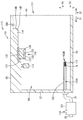
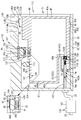
- FIG. 1 is a vertical cross-sectional view schematically showing the internal structure of the printer 10.
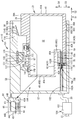
- FIG. 2 is a vertical sectional view of the cartridge mounting portion 110.
- FIG. 3A is a perspective view of the connector 130
- FIG. 3B is a cross-sectional view showing a IIIB-IIIB cross section of FIG. 3A.
- FIG. 4 is a perspective view of the ink cartridge 30 in the standing posture.
- FIG. 5 is a vertical cross-sectional view of the ink cartridge 30 in the standing posture.
- FIG. 6A is a perspective view around the elastic member 90 and the circuit board 64 in the ink cartridge 30 in the upright posture
- FIG. 6B is a perspective view around the circuit board 64 in the ink cartridge 30 in the upright posture. is there.
- FIG. 6A is a perspective view around the elastic member 90 and the circuit board 64 in the ink cartridge 30 in the upright posture
- FIG. 6B is a perspective view around the circuit board 64 in the ink cartridge 30 in the upright posture. is there.
- FIG. 7 is a vertical cross-sectional view showing a state where the ink cartridge 30 is being inserted into the cartridge mounting portion 110.
- FIG. 8 is a vertical cross-sectional view showing a state where the ink cartridge 30 is being inserted into the cartridge mounting portion 110 and is being inserted farther than FIG.
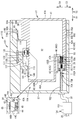
- FIG. 9 is a vertical cross-sectional view showing a state where the ink cartridge 30 is mounted in the cartridge mounting portion 110.
- FIG. 10 is a diagram of the ink cartridge 30 and the cartridge mounting portion 110 in the state of FIG. 9 as viewed from the rear.
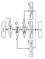
- FIG. 11 is a flowchart for explaining detection of insertion of the ink cartridge 30 into the cartridge mounting portion 110.
- FIG. 12 is a flowchart for explaining insertion detection of the ink cartridge 30 into the cartridge mounting portion 110.
- FIG. 13 is a vertical cross-sectional view showing a state in which the ink cartridge 30 is mounted on the cartridge mounting portion 110 provided with the shaft 145.
- FIG. 14 is a vertical cross-sectional view showing a state in which the ink cartridge 30 in which the elastic member 90 is provided on the lower wall 42 and the convex portion 95 is provided on the upper wall 39 is attached to the cartridge attaching portion 110.
- FIG. 15 is a vertical cross-sectional view of the modified ink cartridge 30.
- the printer 10 records an image by ejecting ink droplets onto a sheet based on an inkjet recording method.
- the printer 10 includes a recording head 21, a cartridge mounting portion 110 (an example of a mounting portion), and an ink tube 20.
- the ink cartridge 30 (an example of a liquid cartridge) in which ink (an example of a liquid) supplied to the recording head 21 is stored is attached to the cartridge mounting unit 110.
- the ink tube 20 connects the recording head 21 and the cartridge mounting portion 110.
- An opening 112 is formed at one end of the cartridge mounting portion 110.
- the ink cartridge 30 and the printer 10 form the system of the present invention.
- FIG. 1 shows a mounting state in which the mounting of the ink cartridge 30 to the cartridge mounting portion 110 is completed
- FIG. 9 shows the ink cartridge 30 and the cartridge mounting portion 110 in FIG. There is. That is, FIG. 9 shows the mounted state of the ink cartridge 30.
- the direction in which the ink cartridge 30 is inserted into the cartridge mounting portion 110 is defined as the front direction 51 (an example of the insertion direction). Further, the posture of the ink cartridge 30 when the ink cartridge 30 is inserted into the cartridge mounting portion 110 forward and mounted is defined as the standing posture. That is, in the mounted state, the ink cartridge 30 is in the standing posture. 1, FIG. 4 to FIG. 10, and FIG. 13 to FIG. 15, the ink cartridge 30 in the standing posture is shown. Further, the direction opposite to the front direction 51 and in which the ink cartridge 30 is pulled out from the cartridge mounting portion 110 is defined as the rear direction 52. In this embodiment, a horizontal direction orthogonal to the gravity direction is defined, and the horizontal direction is parallel to the insertion direction.
- the front direction 51 and the rear direction 52 are parallel to the horizontal direction (direction orthogonal to the gravity direction).
- the front direction 51 and the back direction 52 are directions intersecting with the gravity direction.
- the gravity direction is defined as the downward direction 53, and the direction opposite to the gravity direction is defined as the upward direction 54.
- the directions orthogonal to the front direction 51 and the down direction 53 are defined as the right direction 55 and the left direction 56. More specifically, when the ink cartridge 30 is in the upright posture (the posture shown in FIG. 1), as shown in FIGS. 4 and 6A, when the ink cartridge 30 is viewed from the rear to the front,
- the direction extending to the right is defined as the right direction 55, and the direction extending to the left is defined as the left direction 56.
- the front direction 51 and the rear direction 52 are defined as the front-back direction.
- the upward direction 54 and the downward direction 53 are defined as the up-down direction.
- the right direction 55 and the left direction 56 are defined as the left and right directions.
- the left-right direction is the width direction of the ink cartridge 30
- the up-down direction is the height direction of the ink cartridge 30
- the front-back direction is the depth direction of the ink cartridge 30.
- the ink cartridge 30 In the standing posture, the ink cartridge 30 is inserted into the cartridge mounting portion 110 through the opening 112 (see FIGS. 7 and 8) and mounted (see FIG. 9). In the standing posture, the ink cartridge 30 is pulled out rearward from the cartridge mounting portion 110.
- the ink that can be used in the printer 10 is stored in the ink cartridge 30.
- the ink cartridge 30 and the recording head 21 are connected by the ink tube 20.
- the recording head 21 includes a sub tank 28.
- the sub tank 28 temporarily stores the ink supplied through the ink tube 20.
- the recording head 21 ejects the ink supplied from the sub tank 28 from the nozzle 29 by an inkjet recording method. Specifically, a drive voltage is selectively applied from a head control substrate (not shown) provided in the recording head 21 to the piezo element 29A provided corresponding to each nozzle 29. As a result, ink is ejected from the nozzle 29.
- the printer 10 includes a feeding tray 15, a feeding roller 23, a conveying roller pair 25, a platen 26, a discharging roller pair 27, and a discharging tray 16.
- the sheet fed from the feeding tray 15 to the conveying path 24 by the feeding roller 23 is conveyed onto the platen 26 by the conveying roller pair 25.
- the recording head 21 ejects ink onto a sheet of paper passing over the platen 26. As a result, the image is recorded on the paper.
- the sheet that has passed through the platen 26 is discharged by the discharge roller pair 27 to the discharge tray 16 provided on the most downstream side of the transport path 24.
- the cartridge mounting portion 110 includes a cartridge holder 101, a tube 102 (an example of a distribution tube), a tank 103, an optical sensor 113, a rib 114 (an example of a wall), and a connector 130. Is equipped with.
- the cartridge holder 101 shown in FIG. 2 constitutes a housing of the cartridge mounting portion 110.
- the cartridge holder 101 has a box shape.
- An internal space 104 (an example of a space) is formed in the cartridge holder 101.
- the cartridge holder 101 includes a rear wall 57, a lower wall 59 (an example of a bottom wall), an upper wall 58 (an example of a ceiling wall), and a pair of side walls 60.
- the lower wall 59 extends rearward from the lower end of the inner wall 57.
- the upper wall 58 is vertically separated from the lower wall 59 and extends rearward from the upper end of the inner wall 57.
- the pair of side walls 60 extends rearward from the right end portion and the left end portion of the back wall 57.
- the side wall 60 extending from the right end of the back wall 57 is connected to the right end of the lower wall 59 and the right end of the upper wall 58.
- the side wall 60 extending from the left end of the inner wall 57 is connected to the left end of the lower wall 59 and the left end of the upper wall 58. That is, the pair of side walls 60 are separated from each other in the left-right direction, and each connect the upper wall 58 and the lower wall 59.
- the front end of the cartridge holder 101 facing the back wall 57 in the front-rear direction is an opening 112 that is connected to the internal space 104 of the cartridge holder 101.
- the opening 112 faces when the user uses the printer 10.
- the inner space 104 of the cartridge holder 101 is partitioned by a back wall 57, a lower wall 59, an upper wall 58, and a pair of side walls 60.
- the internal space 104 of the cartridge holder 101 is partitioned into four chambers by a partition wall (not shown).
- the pipe 102, the tank 103, the optical sensor 113, the rib 114, and the connector 130 are provided corresponding to each room in the partitioned internal space 104.
- the number of internal spaces 104 of the cartridge holder 101 is not limited to four.
- the pipe 102 shown in FIG. 2 is made of a cylindrical resin. As shown in FIG. 2, the tube 102 is located below the inner wall 57 of the cartridge holder 101. The tube 102 projects rearward from the inner wall 57 of the cartridge holder 101. The rear end (tip) of the pipe 102 and the front end (base end) of the pipe 102 are open.
- a valve 115 and a coil spring 116 are housed in the internal space 102A of the pipe 102.
- the valve 115 opens and closes the opening 102B formed at the tip of the pipe 102 by moving along the front-rear direction.
- the coil spring 116 biases the valve 115 rearward. Therefore, the valve 115 closes the opening 102B when the external force is not applied (the ink cartridge 30 is not mounted in the cartridge mounting portion 110). Further, the rear end of the valve 115 biased by the coil spring 116 projects rearward from the opening 102B when no external force is applied.
- a notch (not shown) is formed in the tip portion of the side wall of the pipe 102 (specifically, the side wall behind the portion of the valve 115 that closes the opening 102B (front end portion of the valve 115)).
- Cover 111 As shown in FIG. 1, there is a cover 111 near the opening 112 of the cartridge holder 101.
- the cover 111 can expose or cover the opening 112 to the outside by opening and closing.
- the cover 111 is supported by a rotating shaft 109 extending in the left-right direction near the lower end of the opening 112 of the cartridge holder 101.
- the cover 111 can rotate from the closed position (see FIG. 1) that closes the opening 112 so that the upper end of the cover 111 moves forward, and then can rotate to the open position.
- the cover 111 When the cover 111 is in the open position, the user can insert the ink cartridge 30 into the cartridge holder 101 through the opening 112 of the cartridge holder 101.
- the cover 111 When the cover 111 is in the closed position, the user cannot insert or remove the ink cartridge 30 into or from the cartridge holder 101.
- the tank 103 is located in front of the cartridge holder 101.
- the tank 103 has a box shape capable of storing ink inside.
- the upper portion of the tank 103 is opened to the outside by the atmosphere communication port 124.
- the internal space of the tank 103 communicates with the atmosphere.
- the inner space of the tank 103 communicates with the front end of the tube 102 via the ink tube 20.
- the ink that has flowed out of the internal space 102A of the tube 102 is stored in the tank 103.
- the ink tube 20 communicates with the recording head 21 in the internal space of the tank 103.
- the ink stored in the internal space of the tank 103 is supplied to the recording head 21 through the ink tube 20.
- the cartridge mounting unit 110 does not have to include the tank 103.
- the rear end of the tube 102 is communicated with the recording head 21 by the ink tube 20 without the tank 103.
- optical sensor 113 As shown in FIG. 2, the optical sensor 113 is located near the upper wall 58 of the cartridge holder 101.
- the optical sensor 113 includes a light emitting unit and a light receiving unit.
- the light emitting unit is arranged to the right or left of the light receiving unit with a space from the light receiving unit.
- the optical sensor 113 outputs different detection signals to the controller 1 (see FIG. 1) depending on whether or not the light emitted from the light emitting unit along the left-right direction is received by the light receiving unit. For example, the optical sensor 113 outputs a low level signal to the controller 1 on condition that the light emitted from the light emitting unit cannot be received by the light receiving unit (that is, the received light intensity is less than the predetermined intensity). On the other hand, the optical sensor 113 outputs a high level signal to the controller 1 on condition that the light output from the light emitting unit can be received by the light receiving unit (that is, the light receiving intensity is equal to or higher than a predetermined intensity).
- the controller 1 controls the operation of the printer 10, and is composed of, for example, a CPU, a ROM, a RAM, and the like.
- a cover sensor 118 is provided near the upper end of the opening 112 of the cartridge holder 101.
- the cover sensor 118 includes a light emitting unit and a light receiving unit. In the cover sensor 118, when the cover 111 is at the closed position, the optical path of the light emitted from the light emitting unit to the light receiving unit is blocked by the cover 111, so that the cover sensor 118 outputs a low level signal to the controller 1.
- the cover sensor 118 At the position where the cover 111 is not in the closed position, in other words, at the position where the cover 111 is away from the cover sensor 118, the optical path of the light emitted from the light emitting unit to the light receiving unit is not blocked by the cover 111, so the cover sensor 118 outputs a high level signal. Is output to the controller 1.
- the rib 114 is provided on the upper wall 58.
- the rib 114 is behind the optical sensor 113.
- the rib 114 projects downward from the upper wall 58 and extends along the front-rear direction.
- the rib 114 is provided at the center of the upper wall 58 in the left-right direction.
- the lower portion of the rearward-facing surface 114A of the rib 114 is an inclined surface 114B that extends upward as it goes rearward. It should be noted that the entire surface 114A may be the inclined surface 114B.
- the connector 130 includes a contact point 132 and a case 131 that houses the contact point 132.
- a substrate 133 is fixed near the upper wall 58 of the cartridge holder 101.
- the substrate 133 is behind the tube 102 and the optical sensor 113 and in front of the rib 114.
- the substrate 133 is fixed to the cartridge holder 101.
- the case 131 of the connector 130 is fixed to the lower surface of the substrate 133 with screws, solder or the like (not shown). That is, the connector 130 is fixed to the upper wall 58 of the cartridge holder 101 via the substrate 133.
- the connector 130 does not necessarily have to be fixed to the cartridge holder 101.
- the connector 130 may be removably attached to the lower surface of the substrate 133 by fitting or the like.
- the case 131 has a substantially rectangular parallelepiped shape.
- a notch 135 is formed in the case 131 from the lower surface 131A to the front surface 131B to the upper surface 131C.
- Four notches 135 are formed at intervals in the left-right direction.
- Four internal spaces are formed in the case 131 by the four notches 135.
- One contact 132 is arranged in each of the four internal spaces. That is, the connector 130 has four contacts 132.
- the number of notches 135 is not limited to four. That is, the number of contacts 132 included in the connector 130 is not limited to four.
- the contact point 132 is supported by the case 131 in the internal space formed by the notch 135.
- the contact 132 is composed of a member having conductivity and elasticity.
- the lower end portion 132A of the contact point 132 projects downward from the lower surface 131A of the case 131.
- the lower end portion 132A of the contact point 132 is elastically deformable upward.
- the upper end 132B (see FIG. 3B) of the contact 132 is mounted on the board 133.
- the contact 132 is electrically connected to the electric circuit also mounted on the board 133.
- the contact 132 is electrically connected to the electric circuit.
- the electric circuit is electrically connected to the controller 1 (see FIG. 1).
- the case 131 includes a rear wall 136 (an example of a wall), a front wall 137, a right wall 138, and a left wall 139.
- the rear wall 136, the front wall 137, the right wall 138, and the left wall 139 are walls protruding downward from the lower surface 131A of the case 131.
- the lower ends of the rear wall 136, the front wall 137, the right wall 138, and the left wall 139 are below the lower end of the contact point 132.
- the rear wall 136 is behind the lower end portion 132A of the contact point 132.
- the front wall 137 is located in front of the lower end 132A of the contact 132.
- the rear wall 136 and the front wall 137 are lined up in the front-rear direction.
- the right wall 138 is on the right side of the lower end portion 132A of the contact point 132.
- the left wall 139 is on the left side of the lower end portion 132A of the contact point 132.
- the right wall 138 and the left wall 139 are arranged in the left-right direction.
- the front end of the right wall 138 is connected to the right end of the front wall 137.
- the rear end of the right wall 138 is connected to the right end of the rear wall 136.
- the front end of the left wall 139 is connected to the left end of the front wall 137.
- the rear end of the left wall 139 is connected to the left end of the rear wall 136.
- the ink cartridge 30 shown in FIGS. 4 to 6 is a container that stores ink.
- the ink cartridge 30 is housed in each room of the internal space 104 (see FIG. 2) divided into four parts of the cartridge holder 101 of the cartridge mounting portion 110. That is, in this embodiment, the cartridge mounting portion 110 can accommodate four ink cartridges 30.
- Each of the four ink cartridges 30 corresponds to each color of cyan, magenta, yellow, and black. Ink of each color is stored in each of the four ink cartridges 30.
- the number of ink cartridges 30 that can be accommodated in the cartridge mounting unit 110 is not limited to four.
- the ink cartridge 30 includes a housing 31, a seal member 76, a protrusion 67, an elastic member 90, a convex portion 95, a concave portion 43, a support piece 44, and a coil spring. 45 (an example of a biasing member) and a circuit board 64.
- the front-rear direction, the up-down direction, and the left-right direction are defined assuming that the ink cartridge 30 is in the upright posture, unless otherwise specified.
- the housing 31 includes a front wall 40, a rear wall 41, an upper wall 39, a lower wall 42, and a pair of side walls 37 and 38.
- the front wall 40 and the rear wall 41 are separated from each other in the front-rear direction.
- the upper wall 39 is located between the front wall 40 and the rear wall 41, and extends from the upper portion of the front wall 40 to the upper portion of the rear wall 41.
- the lower wall 42 is between the front wall 40 and the rear wall 41, and extends from the lower portion of the front wall 40 to the lower portion of the rear wall 41. That is, the upper wall 39 and the lower wall 42 connect the front wall 40 and the rear wall 41.
- the upper wall 39 and the lower wall 42 are separated from each other in the direction of gravity.
- the side wall 37 and the side wall 38 are separated from each other in the left-right direction.
- the peripheral edges of the side walls 37 and 38 are continuous with the front wall 40, the rear wall 41, the upper wall 39, and the lower wall 42.
- the direction from the rear wall 41 to the front wall 40 corresponds to the front direction 51
- the direction from the front wall 40 to the rear wall 41 corresponds to the rear direction 52
- the direction from the upper wall 39 to the lower wall 42 corresponds to the lower direction 53
- the direction from the lower wall 42 to the upper wall 39 corresponds to the upper direction 54
- the direction from the side wall 38 to the side wall 37 corresponds to the right direction 55
- the direction from the side wall 37 to the side wall 38 corresponds to the left direction 56.
- the front surface 40A of the front wall 40 faces forward
- the rear surface 41A of the rear wall 41 faces rearward
- the lower surface 42A of the lower wall 42 faces downward
- the upper surface 39A of the upper wall 39 faces upward
- the right surface 37A of the side wall 37 faces the right side
- the left surface 38A of the side wall 38 faces the left side.
- the front wall 40 is composed of a front wall 40B and a front wall 40C that is behind the front wall 40B.
- the lower wall 42 is composed of a lower wall 42B and a lower wall 42C above the lower wall 42B.
- the lower wall 42C extends rearward continuously with the lower end of the front wall 40B.
- the lower wall 42B and the lower wall 42C are continuous by the front wall 40C.
- the ink cartridge 30 is in the standing posture unless otherwise specified. That is, the vertical direction, the front-back direction, and the left-right direction are defined assuming that the ink cartridge 30 is in the standing posture.
- the ink cartridge 30 as a whole has a flat shape in which the dimension along the left-right direction is smaller than the dimension along the front-rear direction, and the dimension along each of the up-down direction and the front-rear direction is larger than the dimension along the left-right direction. .
- the ink cartridge 30 is inserted into the cartridge holder 101 through the opening 112 of the cartridge holder 101 of the cartridge mounting portion 110 so that the ink cartridge 30 is mounted frontward, and is pulled out rearward.
- the housing 31 includes a storage chamber 32 that stores ink therein.
- the storage chamber 32 is formed between the front wall 40 and the rear wall 41, between the upper wall 39 and the lower wall 42, and between the pair of side walls 37 and 38.
- the surface on the side opposite to the side surface, the surface on the side opposite to the right surface 37A of the side wall 37 (the left surface of the side wall 37), and the surface on the side opposite to the left surface 38A of the side wall 38 (the right surface of the side wall 38) define the storage chamber 32. ..
- At least the rear wall 41 of the housing 31 has a light-transmitting property so that the liquid surface of the ink stored in the storage chamber 32 can be visually recognized from the outside.
- the housing 31 includes a cylinder 75 protruding forward from the front surface 40A of the front wall 40B.
- the cylinder 75 extends in the front-rear direction.
- the through hole 75A (an example of a liquid circulation hole) of the cylinder 75 also extends in the front-rear direction.
- the direction in which the cylinder 75 and the through hole 75A extend corresponds to the insertion direction of the ink cartridge 30.
- the rear end of the through hole 75A communicates with the storage chamber 32.
- An opening 75B is formed at the front end of the cylinder 75. That is, the through hole 75A of the cylinder 75 is opened forward in the front surface 40A of the front wall 40B. That is, the through hole 75A penetrates the front wall 40C and communicates the storage chamber 32 with the outside of the housing 31.
- a valve 79 and a coil spring 80 are housed in the through hole 75A.
- the valve 79 opens and closes the opening 75B by moving along the front-rear direction.
- the coil spring 80 biases the valve 79 forward. Therefore, the valve 79 is in close contact with the seal member 76 when no external force is applied.
- the valve 79 separates from the seal member 76 when the external force is applied.
- the ink stored in the storage chamber 32 is supplied to the outside from the opening 75B through the through hole 75A.
- the configuration for switching the communication of the through hole 75A with the atmosphere is not limited to the one using the valve 79, and the opening 75B may be closed by, for example, attaching a seal to the tube 75.
- the atmosphere communication port 140 is formed on the upper wall 39 of the housing 31. Before the ink cartridge 30 is inserted into the cartridge mounting portion 110, the atmosphere communication port 140 is sealed by the seal 141. The seal 141 can be peeled off from the atmosphere communication port 140. By removing the seal 141 before the ink cartridge 30 is inserted into the cartridge mounting portion 110, the storage chamber 32 communicates with the atmosphere via the atmosphere communication port 140. The storage chamber 32 may be communicated with the atmosphere by means other than removing the seal 141.
- the atmosphere communication port 140 may be provided with a valve, and the presence or absence of the atmosphere communication of the storage chamber 32 may be switched by the valve.
- the front wall 40, the rear wall 41, the upper wall 39, the lower wall 42, and the pair of side walls 37, 38 may be composed of a plurality of walls like the front wall 40, or like the rear wall 41. It may be composed of one wall.
- front surface 40A of the front wall 40 of the ink cartridge 30, the rear surface 41A of the rear wall 41, the upper surface 39A of the upper wall 39, the lower surface 42A of the lower wall 42, the right surface 37A of the side wall 37, and the left surface 38A of the side wall 38 are not necessarily 1 It does not have to be in one plane.
- the front surface 40A of the front wall 40 is a surface that can be visually recognized when the ink cartridge 30 in the standing posture is viewed from the front to the rear.
- the frontmost surface of the housing 31, the frontmost surface, and the surface in front of the center of the dimension of the rear surface 41A in the front-rear direction are included in the concept of the front surface of the present invention.
- the rear surface 41A of the rear wall 41 is a surface that can be visually recognized when the ink cartridge 30 in the standing posture is viewed from the rear to the front.
- the rearmost surface of the housing 31 and the rearward surface of the rearmost surface and the frontmost surface of the housing 31 are the rear surface of the present invention. Included in the concept.
- the upper surface 39A of the upper wall 39 is a surface that can be visually recognized when the ink cartridge 30 in the standing posture is viewed from above.
- the uppermost surface of the housing 31, the uppermost surface, and the surface above the center of the vertical dimension of the lower surface 42A are included in the concept of the upper surface of the present invention.
- the lower surface 42A of the lower wall 42 is a surface that can be visually recognized when the ink cartridge 30 in the standing posture is viewed from below.
- the lowermost surface of the casing 31, the lowermost surface, and the lower surface of the uppermost surface of the casing 31 below the center of the vertical dimension are the concept of the lower surface of the present invention. include.
- the right surface 37A of the side wall 37 is a surface that can be visually recognized when the casing 31 of the ink cartridge 30 in the standing posture is viewed from right to left.
- the left surface 38A of the side wall 38 is a surface that can be visually recognized when the casing 31 of the ink cartridge 30 in the standing posture is viewed from left to right.
- the seal member 76 As shown in FIG. 5, the seal member 76 is in the through hole 75A.
- the seal member 76 is made of an elastic member such as rubber.
- the seal member 76 is a ring-shaped member, and has a circular through hole 76A in the center.
- the diameter of the through hole 76A is smaller than the diameter of the tube 102 (see FIG. 2) of the cartridge mounting portion 110.
- the seal member 76 is arranged near the opening 75B of the through hole 75A of the cylinder 75 so that the through hole 76A coincides with the position of the opening 75B.
- the diameter of the seal member 76 is larger than the diameter of the opening 75B.
- the seal member 76 is prevented from coming off the cylinder 75 by a known means.
- the seal member 76 may be fixed to the cylinder 75 by being sandwiched between the cylinder 75 and a cap (not shown) covering the cylinder 75, or may be fixed to the cylinder 75 by being bonded to the cylinder 75. It may have been done.
- Protrusion 67 As shown in FIGS. 4 and 5, on the upper surface 39A of the upper wall 39, there is a protrusion 67 protruding upward. The protrusion 67 extends in the front-rear direction.
- the right surface or the left surface of the protrusion 67 is a surface on which the light emitted by the optical sensor 113 (see FIG. 2) of the cartridge mounting portion 110 falls.
- the surface of the projection 67 on which the light strikes can also be called the light blocking surface.
- the protrusion 67 is a resin plate containing a color material (black pigment) capable of blocking or attenuating light, for example.
- a material such as an aluminum foil that cannot transmit light may be attached to at least the light blocking surface of the protrusion 67.
- the elastic member 90 As shown in FIGS. 4 and 5, the elastic member 90 is provided on the upper surface 39A of the upper wall 39. The elastic member 90 is behind the protrusion 67. The elastic member 90 is in the range R1 behind the intermediate position P1 of the front end (front surface 40A) and the rear end (rear surface 41A) of the housing 31 in the front-rear direction. As shown in FIGS. 4, 5 and 6A, the elastic member 90 projects upward from the upper surface 39A and extends upward as it goes rearward.
- the elastic member 90 is elastically deformable.
- the elastic member 90 is a leaf spring having a dimension in the front-rear direction longer than that in the up-down direction.
- the elastic member 90 is elastically deformed in the vertical direction, so that the tip (rear end) can be bent so as to move vertically (see FIG. 9).
- the upper surface 90A of the elastic member 90 (an example of the first contact surface) is directed obliquely upward to the front. In other words, the upper surface 90A faces forward and upward.
- the upper surface 90A is above the storage chamber 32.
- the dimension LA (see FIG. 5) in the front-rear direction of the upper surface 90A is longer than the dimension LB (see FIG. 10) in the left-right direction of the upper surface 90A. That is, the upper surface 90A extends in the front-rear direction.
- the horizontal dimension LB (see FIG. 10) of the upper surface 90A is longer than the horizontal dimension LC (see FIG. 10) of the rib 114.
- the size LA may be smaller than or equal to the size LB. Further, the size LB may be equal to or smaller than the size LC.
- FIG. 10 only one room of the internal space 104 partitioned into four rooms is shown, and the other three rooms are not shown.
- the convex portion 95 projects downward from the lower surface 42A of the lower wall 42.
- the convex portion 95 is in the range R1 behind the intermediate position P1 in the front-rear direction.
- the ink cartridge 30 is viewed in the vertical direction, that is, in a plan view, at least a part of the convex portion 95 overlaps with the elastic member 90.
- the rear surface 95A of the convex portion 95 is inclined so as to go upward as it goes rearward.
- the front surface 95B of the convex portion 95 is inclined so as to go upward as it goes forward.
- the lower surface 95C (an example of the second contact surface) of the convex portion 95 is between the rear surface 95A and the front surface 95B.
- the rear end of the lower surface 95C is connected to the front end of the rear surface 95A.
- the front end of the lower surface 95C is connected to the rear end of the front surface 95B.
- the lower surface 95C faces downward.
- the lower surface 95C is below the storage chamber 32. That is, the lower surface 95C is on the opposite side of the elastic member 90 with the storage chamber 32 interposed therebetween.
- the upper wall 39 has a recess 43 recessed downward from the upper surface 39A.
- the recess 43 is located behind the protrusion 67 and ahead of the elastic member 90.
- the coil spring 45 is arranged in the recess 43.
- the lower end of the coil spring 45 is connected to the bottom surface 43A of the recess 43.
- the upper end of the coil spring 45 is connected to the lower surface of the support piece 44.
- the support piece 44 is a member having a substantially rectangular parallelepiped shape in the present embodiment, but may have a shape other than the rectangular parallelepiped.
- At least a part of the rear surface 44A of the support piece 44 (the upper portion of the rear surface 44A in the present embodiment) is an inclined surface 44B that is inclined downward toward the rear.
- At least part of the front surface 44C of the support piece 44 (the upper portion of the front surface 44C in the present embodiment) is an inclined surface 44D that is inclined downward toward the front. Note that all of the rear surface 44A may be the inclined surface 44B and all of the front surface 44C may be the inclined surface 44D.
- the support piece 44 supports the circuit board 64 on its upper surface.
- the rear surface of the circuit board 64 may be inclined like the inclined surface 44B, or the front surface of the circuit board 64 may be inclined like the inclined surface 44D.
- the circuit board 64 has a board 63 and electrodes 65.
- the circuit board 64 is a board 63, which is a rigid board made of glass epoxy or the like, on which a memory (not shown) and four electrodes 65 (an example of contacts on the cartridge side) are formed.
- the number of electrodes 65 is determined according to the number of contacts 132 (see FIG. 2) of the cartridge mounting portion 110, and is not limited to four.
- the circuit board 64 is not limited to the rigid board, but may be a flexible board having flexibility, for example.
- the substrate 63 is adhered to the upper surface of the support piece 44 with a photocurable resin.
- the circuit board 64 may be adhered to the upper surface of the support piece 44 with an adhesive other than the photo-curable resin. Further, the circuit board 64 may be crimped or may be attached to the upper surface of the support piece 44 by means other than adhesion.
- Information about the ink cartridge 30 is stored in the memory so that it can be read by the controller 1 (see FIG. 1) of the printer 10.
- the information regarding the ink cartridge 30 is data indicating information such as a lot number, a manufacturing date, and an ink color.
- a battery may be mounted on the substrate 63. The battery supplies electricity to the memory and is electrically connected to the memory.
- each of the four electrodes 65 corresponds to each of the four contacts 132 of the cartridge mounting portion 110. That is, the number of the electrodes 65 is not limited to four like the contacts 132. As shown in FIGS. 4 and 6A, each of the electrodes 65 extends in the front-rear direction and is arranged in the left-right direction with a space therebetween. Each electrode 65 is electrically connected to the memory.
- the circuit board 64 can move to a first position shown in FIGS. 4 and 5 and a second position not shown by the coil spring 45 contracting and extending in the vertical direction, that is, elastically deforming in the vertical direction.
- the second position is a position below the first position. That is, the support piece 44 at the second position is in the recess 43 more than at the first position.
- the circuit board 64 is in the first position.
- the coil spring 45 is contracted from its natural length. That is, the coil spring 45 biases the support piece 44 and the circuit board 64 upward, that is, to the first position in a state where the coil spring 45 contracts from its natural length.
- the atmosphere communication port 140 is sealed by the seal 141, so the storage chamber 32 is not in communication with the atmosphere. Therefore, the seal 141 is peeled off before the ink cartridge 30 is mounted in the cartridge mounting portion 110. As a result, the storage chamber 32 is opened to the atmosphere. Further, in the ink cartridge 30 before being mounted in the cartridge mounting portion 110, the valve 79 is in close contact with the seal member 76. As a result, the ink stored in the storage chamber 32 is prevented from flowing out of the ink cartridge 30 through the through hole 76A.
- the optical sensor 113 outputs a high-level detection signal to the controller 1 (see FIG. 1). Further, in the cartridge mounting portion 110 in which the ink cartridge 30 is not mounted, the valve 115 closes the opening 102B, and the rear end portion of the valve 115 projects rearward from the opening 102B.
- the ink cartridge 30 is inserted forward into the cartridge holder 101 through the opening 112 of the cartridge mounting portion 110 (see FIG. 7).
- the ink cartridge 30 is inserted into the cartridge holder 101 in the upright posture, but not limited to this, it may be inserted into the cartridge holder 101 in a posture inclined with respect to the horizontal direction.
- the tube 102 of the cartridge mounting portion 110 penetrates through the through hole 76A (opening 75B) of the seal member 76, and the cylinder 75. To the through hole 75A. At this time, the outer peripheral surface of the tube 102 and the inner peripheral surface (the surface defining the through hole 76A) of the seal member 76 are in close contact with each other. As a result, the cylinder 75 and the tube 102 are sealed and the cylinder 75 is positioned so that the ink does not leak into the cartridge holder 101 in the mounted state.
- the pipe 102 that has entered the through hole 75A contacts the valve 79 and pushes it backward.
- the valve 79 is separated from the seal member 76 against the rearward biasing force of the coil spring 80.
- the valve 79 contacts the valve 115 from the rear and pushes it forward. Then, the valve 115 moves forward against the biasing force of the coil spring 116. As a result, the internal space 102A of the tube 102 communicates with the outside of the tube 102 through the opening 102B.
- the ink stored in the storage chamber 32 can be circulated to the tank 103 and the recording head 21 via the internal space 102A of the tube 102.
- the circuit board 64 is not yet in contact with the cartridge mounting portion 110.
- the ink cartridge 30 is inserted forward into the cartridge holder 101 with the convex portion 95 being supported by the lower wall 59.
- the convex portion 95 contacts the rear end of the lower wall 59 from the rear. ..
- the rear end of the lower wall 59 is guided relatively to the front surface 95B of the convex portion 95, so that the convex portion 95 rides on the lower wall 59.
- the convex portion 95 is supported by the lower wall 59.
- the inclined surface 44D of the support piece 44 contacts the rear wall 136 from the rear.
- the rear wall 136 is relatively guided along the inclined surface 44D by the reaction force acting from the rear wall 136 to the inclined surface 44D.
- the support piece 44 and the circuit board 64 move from the first position to the second position against the biasing force of the coil spring 45.
- the support piece 44 and the circuit board 64 move below the rear wall 136.
- the elastic member 90 elastically deforms. Specifically, the elastic member 90 has its tip (rear end) elastically deformed downward. That is, the elastic member 90 is elastically deformed to be in a state of being compressed downward from a state of not being elastically deformed. As shown in FIG. 8, the elastically deformed elastic member 90 has an upwardly convex curved shape.
- the electrode 65 comes into contact with the corresponding contact 132 and becomes conductive, the voltage Vc is applied to the electrode 65, the electrode 65 is grounded, or power is supplied to the electrode 65.
- the memory mounted on the circuit board 64 is electrically connected to the controller 1 (see FIG. 1) by the electrical connection between the contact 132 and the electrode 65. As a result, the controller 1 can access the memory. As a result, the data stored in the memory is input to the controller 1 (see FIG. 1).
- the state shown in FIG. 9 is the mounted state.
- the tube 102 of the cartridge mounting portion 110 has entered the through hole 75A of the cylinder 75.
- ink can flow from the storage chamber 32 to the internal space 102A of the tube 102.
- the protrusion 67 is located between the light emitting portion and the light receiving portion of the optical sensor 113. Thereby, the protrusion 67 blocks light from traveling from the light emitting portion to the light receiving portion. That is, the protrusion 67 is on the optical path of the light emitted from the light emitting unit in the mounted state. That is, in the mounted state, the optical sensor 113 is at a position where the light blocking surface of the protrusion 67 is located on the optical path of the light emitted from the light emitting unit. At this time, the optical sensor 113 outputs a low-level detection signal to the controller 1 (see FIG. 1).
- the front wall 137 of the connector 130 is in front of the circuit board 64 in the mounted state. Further, the rear wall 136 of the connector 130 is behind the circuit board 64. As described above, in the mounted state, the front wall 137 and the rear wall 136 sandwich the electrode 65 from the front and the back. That is, the rear wall 136 and the front wall 137 are arranged in the front-rear direction so as to sandwich the electrode 65.
- the right wall 138 of the connector 130 in the mounted state, is on the right side of the circuit board 64, and the left wall 139 of the connector 130 is on the left side of the circuit board 64.
- the lower end of the right wall 138 and the lower end of the left wall 139 are below the electrode 65.
- the right wall 138 and the left wall 139 sandwich the electrode 65 from the left and right. That is, the right wall 138 and the left wall 139 are arranged in the left-right direction so as to sandwich the electrode 65.
- the upper surface 90A of the elastic member 90 is in contact with the rib 114 from below in the mounted state.
- the elastic member 90 is elastically deformed as described above. That is, in the mounted state, the elastic member 90 is in a state of being compressed by elastic deformation between the housing 31 and the rib 114.
- the lower surface 95C of the convex portion 95 is in contact with the lower wall 59 from above.
- the elastic member 90 in the mounted state, when the elastic member 90 is elastically deformed, the upper surface 90A of the elastic member 90 contacts the rib 114 from below and the lower surface 95C of the convex portion 95 contacts the lower wall 59 from above. Accordingly, the resistance force against the rearward movement of the ink cartridge 30 acts between the upper surface 90A and the rib 114 and between the lower surface 95C and the lower wall 59. Due to this resistance, the ink cartridge 30 is held in the cartridge holder 101. In other words, the ink cartridge 30 is in a state of being pressed into the cartridge holder 101.
- the vertical distance from the lower surface 95C to the upper end of the elastic member 90 is longer than the distance from the floor surface of the lower wall 59 of the cartridge holder 101 to the surface of the rib 114 facing downward.
- a part of the contact position P2 of the upper surface 90A and the rib 114 is the same position in the front-rear direction as a part of the contact position P3 of the lower surface 95C and the lower wall 59.
- the contact position P2 of the upper surface 90A and the rib 114 is the same position in the left-right direction as the lower surface 95C and a part of the contact position P3 of the lower wall 59. That is, the contact position P2 of the upper surface 90A and the rib 114 overlaps the contact position P3 of the lower surface 95C and the lower wall 59 in a plan view in the mounted state.
- the contact position P2 and the contact position P3 overlap in a plan view in the mounted state, but they do not have to overlap.
- the contact position P2 and the contact position P3 are preferably behind the intermediate position P1, but at least one of the contact position P2 and the contact position P3 may be ahead of the intermediate position P1. ..
- W2 is the dimension of the electrode 65 in the left-right direction, as shown in FIG. 6 (A).
- the four electrodes 65 have the same horizontal dimension, but when the four electrodes 65 have different horizontal dimensions, the smallest value is preferably W2.
- L1 indicates the electrode 65 and the contact point 132 from the contact position P4 between the tube 102 and the surface defining the through hole 75A (the inner surface of the seal member 76). Is the distance in the front-rear direction to the contact position P5.
- L2 is the distance in the front-rear direction from the contact position P4 to the contact position P2 between the upper surface 90A and the rib 114, as shown in FIG.
- the user When the ink cartridge 30 is pulled out from the cartridge holder 101 of the cartridge mounting portion 110, the user holds the ink cartridge 30 and pulls the ink cartridge 30 rearward. At this time, the ink cartridge 30 is pulled rearward by a force larger than the above resistance force, whereby the ink cartridge 30 moves rearward. As a result, the user can take out the ink cartridge 30 from the cartridge mounting portion 110.
- the controller 1 determines whether or not the cover 111 is in the closed position, depending on whether or not the signal output from the cover sensor 118 is a low level signal (see FIG. 1). S10).
- the controller 1 determines whether or not the memory 66 of the circuit board 64 of the ink cartridge 30 can be accessed, that is, whether or not the memory 66 can be written or read. S20).
- the controller 1 can access the memory of the circuit board 64. If the contacts 132 do not contact the electrodes 65 of the circuit board 64, the controller 1 cannot access the memory 66 of the circuit board 64.
- the controller 1 determines that the ink cartridge 30 is not mounted in the cartridge mounting unit 110 (S30). In this case, the controller 1 prompts the user to “mount the ink cartridge 30 by displaying a message on a display panel (not shown) provided in the housing of the printer 10 or a buzzer or voice from a speaker (not shown). It has not been done ”.
- the controller 1 determines whether the signal output from the optical sensor 113 to the controller 1 is at a high level or a low level.
- the optical sensor 113 outputs a low level signal to the controller 1.
- the optical sensor 113 outputs a high level signal to the controller 1.
- the controller 1 determines that the abnormal ink cartridge 30 is mounted in the cartridge mounting unit 110 (S50). In this case, the controller 1 prompts the user to "display an abnormal ink cartridge 30" by displaying a message on a display panel (not shown) provided in the housing of the printer 10 or a buzzer or voice from a speaker (not shown). Is attached ”.
- the controller 1 determines that the normal ink cartridge 30 is mounted in the cartridge mounting unit 110 (S60).
- the controller 1 determines whether or not the ink cartridge 30 is mounted in the cartridge mounting portion 110 based on whether or not the circuit board 64 is accessible, and based on the level of the signal output from the optical sensor 113. Then, it is determined whether or not the ink cartridge 30 mounted in the cartridge mounting portion 110 is normal.
- the controller 1 determines whether or not the ink cartridge 30 is mounted in the cartridge mounting portion 110 based on the level of the signal output from the optical sensor 113, and based on whether or not the circuit board 64 is accessible, the cartridge mounting portion. It may be determined whether or not the ink cartridge 30 mounted in 110 is normal.
- the determination procedure in this case will be described with reference to the flowchart of FIG.
- the controller 1 determines whether the signal output from the optical sensor 113 to the controller 1 is at a high level or a low level. A determination is made (S120).
- the controller 1 determines that the ink cartridge 30 is not mounted in the cartridge mounting unit 110 (S130). In this case, similar to step S30 of FIG. 11, the user is notified that "the ink cartridge 30 is not mounted".
- the controller 1 determines whether the circuit board 64 of the ink cartridge 30 can be accessed (S140).
- the controller 1 determines that the abnormal ink cartridge 30 is mounted in the cartridge mounting unit 110 (S150). In this case, similar to step S50 of FIG. 11, the user is notified that "the abnormal ink cartridge 30 is mounted".
- the controller 1 determines that the normal ink cartridge 30 is mounted in the cartridge mounting unit 110 (S160).
- the rib 114 extends in the front-rear direction. Therefore, even when the position of the ink cartridge 30 with respect to the cartridge mounting portion 110 is displaced in the front-rear direction, it is possible to increase the possibility that the state in which the rib 114 contacts the upper surface 90A can be maintained.
- both the rib 114 and the upper surface 90A extend in the front-rear direction. As a result, the rib 114 and the upper surface 90A can be in line contact with each other in a side view. As a result, the above-mentioned creep deformation can be suppressed.
- the positional deviation of the upper surface 90A in the left-right direction with respect to the rib 114 is maintained as long as the upper surface 90A and the rib 114 are kept in contact with each other. Regardless of the length, the lateral displacement of the electrode 65 can be suppressed within the lateral length of the electrode 65. Accordingly, as long as the state where the upper surface 90A and the rib 114 are in contact with each other is maintained, it is possible to prevent the contact between the contact 132 and the electrode 65 from being released due to the lateral displacement of the electrode 65. ..
- the contact position P2 of the upper surface 90A and the rib 114 and the contact position P3 of the lower surface 95C and the lower wall 59 do not overlap with each other in plan view, the following problem may occur. That is, the force acting on the ink cartridge 30 from the upper wall 58 downward and the force acting on the ink cartridge 30 from the lower wall 59 upward tilts the ink cartridge 30 in the left-right direction or the front-back direction. There is a risk.
- the contact position P2 and the contact position P3 overlap in a plan view. Therefore, it is possible to suppress the inclination of the ink cartridge 30 as described above and stabilize the posture of the ink cartridge 30.
- the contact position P2 of the upper surface 90A and the rib 114 and the contact position P3 of the lower surface 95C and the lower wall 59 are in front of the intermediate position P1, when the ink cartridge 30 is taken out from the cartridge mounting portion 110. Further, if one of the upper surface 90A and the lower surface 95C is caught by the cartridge mounting portion 110, it is difficult to release this catch. However, according to the present embodiment, since the contact position P2 and the contact position P3 are behind the intermediate position P1, when the ink cartridge 30 is taken out of the cartridge mounting portion 110, one of the upper surface 90A and the lower surface 95C is removed. Even if the cartridge mounting portion 110 is caught, it is easy to cancel the catch.
- the circuit board 64 in the mounted state, the circuit board 64 is in front of the rear wall 136, and the lower end of the rear wall 136 is below the contact point 132. Therefore, in the mounted state, the rear wall 136 can prevent the contacts 132 and the electrodes 65 from being touched by a user or the like.
- the circuit board 64 and the rear wall 136 interfere with each other when the ink cartridge 30 is inserted in the cartridge mounting portion 110 in the horizontal direction, the circuit board 64 does not interfere with the rear wall 136.
- the coil spring 45 can be moved to the second position against the biasing force of the coil spring 45. Therefore, it is possible to prevent the rear wall 136 from inhibiting the insertion of the ink cartridge 30 into the cartridge mounting portion 110.
- the cartridge mounting portion 110 may include a shaft 145 (an example of a rod).
- the shaft 145 extends in the left-right direction near the upper wall 58 of the cartridge holder 101 and near the opening 112.
- the shaft 145 is a rod-shaped member that extends in the left-right direction across the internal space 104 of the cartridge holder 101.
- the shaft 145 is, for example, a metal cylinder. Both ends in the left-right direction of the shaft 145 are fixed to the pair of side walls 60 of the cartridge holder 101.
- the upper surface 90A of the elastic member 90 may contact the shaft 145 instead of contacting the rib 114. That is, as shown in FIG. 13, in the mounted state, the elastic member 90 may be in a state of being compressed between the housing 31 and the shaft 145 by elastic deformation. Further, in the mounted state, the rear end 90B of the elastic member 90 is preferably behind the shaft 145.
- the elastic member 90 is provided on the upper surface 39A of the upper wall 39, and the convex portion 95 is provided on the lower surface 42A of the lower wall 42.
- the elastic member 90 in the mounted state, is elastically deformed and compressed upward by the lower surface 90C (an example of the second contact surface) of the elastic member 90 contacting the lower wall 59 from above.
- the upper surface 95D of the convex portion 95 (an example of the first contact surface) is in contact with the rib 114 from below.
- the convex portion 95 may contact the shaft 145 from below.
- the elastic members 90 may be provided on both the upper surface 39A of the upper wall 39 and the lower surface 42A of the lower wall 42.
- the elastic member 90 and the convex portion 95 contact the rib 114 or the shaft 145 from below, but the elastic member 90 and the convex portion 95 contact from below at any portion of the upper wall 58. is there.
- the elastic member 90 and the convex portion 95 may contact the lower surface 58A (see FIG. 2) of the upper wall 58 from below.
- the elastic member 90 is a leaf spring, but it is not limited to a leaf spring.
- the elastic member 90 may be a coil spring.
- the circuit board 64 is supported by the upper wall 39 via the coil spring 45, but the circuit board 64 is supported by the upper wall 39 via an elastic member other than the coil spring 45, such as a leaf spring or rubber. You may.
- the convex portion 95 abuts the lower wall 59 from above, so that the ink cartridge 30 is held in the cartridge holder 101 in cooperation with the elastic member 90.
- the portion of the ink cartridge 30 other than the convex portion 95 may perform the function of the convex portion 95 (the function of holding the ink cartridge 30 in the cartridge holder 101 in cooperation with the elastic member 90).
- the ink cartridge 30 may not include the convex portion 95.
- the lower wall 42 of the housing 31 contacts the lower wall 59 from above.
- the lower surface 42A of the lower wall 42 cooperates with the elastic member 90 to hold the ink cartridge 30 in the cartridge holder 101. That is, in this case, the lower surface 42A is an example of the second contact surface.
- the communication between the through hole 75A and the outside was switched by the valve 79.
- the opening 75B may be sealed with a seal. More specifically, a seal is attached to the front surface of the cylinder 75 when the ink cartridge 30 is not inserted in the cartridge mounting portion 110. As a result, the through hole 76A is sealed by the seal. Therefore, the ink in the storage chamber 32 does not flow from the through hole 76A to the outside of the ink cartridge 30 through the through hole 75A. In the process of inserting the ink cartridge 30 into the cartridge mounting portion 110, the tube 102 breaks through the seal, so that the sealing is released.
- the ink cartridge 30 is not limited to the configuration shown in FIGS. 4 to 6, 13, and 14.
- the ink cartridge 30 may have a configuration as shown in FIG. In the configuration shown in FIG. 15, the outer shape of the ink cartridge 30 is substantially a rectangular parallelepiped, and the ink cartridge 30 does not include the protrusion 67, the cylinder 75, the valve 79, the coil spring 80 and the like.
- the through hole 75A is closed by the seal 142.
- the ink is described as an example of the liquid, but for example, instead of the ink, the pretreatment liquid ejected onto the paper or the like prior to the ink during printing may be stored in the liquid cartridge. Further, water for cleaning the recording head 21 may be stored in the liquid cartridge.
Landscapes
- Ink Jet (AREA)
Abstract
液体カートリッジに貯留可能な液体容積を維持しつつ、液体カートリッジを装着部に装着された状態を維持可能なシステムを提供する。システムは、インクカートリッジ30と、インクカートリッジ30が装着されるカートリッジ装着部110とを備える。インクカートリッジ30は、筐体31の上壁39に設けられた弾性部材90と、筐体31の下壁42に設けられた凸部95とを備える。カートリッジ装着部110は、下壁59と、上壁58と、一対の側壁60とによって区画される内部空間104にインクカートリッジ30を保持可能なカートリッジホルダ101を備える。弾性部材90は、インクカートリッジ30がカートリッジ装着部110に装着された装着状態において、下方から上壁58に当接して筐体31と上壁58の間で弾性変形により圧縮した状態である。凸部95は、装着状態において、上方から下壁59に当接している。
Description
本発明は、液体を貯留する液体カートリッジと当該液体カートリッジが装着可能な装着部とを備えるシステムに関する。
従来から、インクカートリッジと、インクジェット記録装置とを含むシステムが知られている。インクジェット記録装置は、インクカートリッジが装着され及び抜き出される装着部を備える。インクジェット記録装置は、インクカートリッジが装着部に装着された状態を維持するための機構を備えている。
例えば、特許文献1に開示されたプリンタでは、装着部に設けられたレバーが押し下げられることによって、レバーがインクカートリッジに引っ掛かり、インクカートリッジが装着部から抜け出すことが防止されている。当該プリンタでは、レバーが操作されることによって、インクカートリッジが装着部から抜き出し可能な状態となる。
しかしながら、特許文献1に開示されたプリンタでは、レバーを配置するためのスペースが必要であった。これにより、インクカートリッジに貯留可能なインクの容積が少なくなってしまっていた。
装着部がレバーを備えるのでなく、インクカートリッジがレバーを備える構成とすることが考えられる。しかしながら、この場合でも、レバーを配置するためのスペースが必要であることは、特許文献1に開示されたプリンタと同様であるため、インクカートリッジに貯留可能なインクの容積が少なくなってしまう。
本発明は、前述された事情に鑑みてなされたものであり、その目的は、液体カートリッジに貯留可能な液体容積を維持しつつ、液体カートリッジを装着部に装着された状態を維持可能なシステムを提供することにある。
(1) 本発明に係るシステムは、液体カートリッジと、上記液体カートリッジが重力方向と交差する挿入方向に挿入される装着部と、を備える。上記液体カートリッジは、液体を貯留する貯留室を有する筐体と、上記液体カートリッジが上記装着部に装着された装着状態において上記筐体の上記挿入方向の前方に開口しており、上記貯留室と上記筐体の外部とを連通する液体流通孔と、上記装着状態において上方を向き、カートリッジ側接点を有する回路基板と、上記装着状態において上記貯留室より上にあり、上記装着部に当接可能であって上記上方を向く第1当接面と、上記装着状態において上記貯留室を挟んで上記第1当接面の反対側にあり、上記装着部に当接可能な第2当接面と、を備える。上記装着部は、底壁と、上記底壁に対し上記重力方向に離間した天壁と、上記天壁及び上記底壁を繋ぎ、上記重力方向及び上記挿入方向と交差する幅方向に離間した一対の側壁とによって区画される空間に上記液体カートリッジを保持可能なカートリッジホルダと、上記装着状態において上記液体流通孔内にあり、上記貯留室から液体が流通する流通管と、上記天壁にあり、上記装着状態において上記カートリッジ側接点に接触可能な接点を有するコネクタと、上記天壁から下方へ向かって延び且つ上記挿入方向に沿って延びる壁と、を備える。上記第1当接面または上記第2当接面の少なくとも一方は、上記重力方向に弾性変形可能な弾性部材にある。上記弾性部材は、上記装着状態において、上記筐体と上記底壁または上記天壁の一方との間で弾性変形により圧縮した状態である。
上記構成によれば、装着状態において、弾性部材は弾性変形した状態で底壁または天壁の一方に当接している。よって、弾性部材は、復元力によって底壁または天壁の一方に圧接する。一方、底壁または天壁の他方に当接している面には、弾性部材の復元力の反力が作用する。これにより、当該面は、底壁または天壁の他方に圧接する。その結果、液体カートリッジにレバーなどの部品を追加することなく、液体カートリッジを装着状態に維持することができる。また、ユーザは液体カートリッジを重力方向に動かすことなく、挿入方向と逆向きに引っ張るだけで液体カートリッジを取り出すことができる。
(2) 例えば、上記第1当接面または上記第2当接面の一方は、上記弾性部材にある。上記第1当接面または上記第2当接面の一方は、上記装着状態において下方から上記天壁と当接する。上記第1当接面または上記第2当接面の他方は、上記装着状態において上方から上記底壁と当接する。
(3) 上記第1当接面または上記第2当接面は、上記装着状態において下方から上記壁と当接する。
上記構成によれば、壁が挿入方向に延びている。そのため、液体カートリッジの装着部に対する位置が挿入方向にずれた場合であっても、壁が第1当接面または第2当接面と接触した状態を維持できる可能性を高めることができる。
(4) 上記第1当接面または上記第2当接面のうち上記壁に当接する面は、上記挿入方向に延びている。
仮に、液体カートリッジを側方から視た側面視において、壁及び面が点接触である場合、壁または面の少なくとも一方は、当接する相手からの力の作用によってクリープ変形し易い。しかし、上記構成によれば、壁及び面の双方が挿入方向に延びている。これにより、側面視において、壁及び面を線接触とすることができる。その結果、上述したクリープ変形を抑制することができる。
(5) 上記第1当接面または上記第2当接面のうち上記壁に当接する当接面は、上記幅方向において上記壁よりも長い。上記壁の上記幅方向の両端のうちの上記幅方向の一方側の端と、上記当接面の上記幅方向の両端のうちの上記一方側の端との上記幅方向の距離W1が、下記の式1を満たす。
W1<(L2/L1)×W2・・・(式1)
但し、W2は、上記カートリッジ側接点の上記幅方向の長さであり、L1は、上記流通管と上記液体流通孔を区画する面との当接位置から、上記カートリッジ側接点と上記接点との当接位置までの上記挿入方向の距離であり、L2は、上記流通管と上記面との当接位置から、上記当接面と上記壁との当接位置までの上記挿入方向の距離である。
W1<(L2/L1)×W2・・・(式1)
但し、W2は、上記カートリッジ側接点の上記幅方向の長さであり、L1は、上記流通管と上記液体流通孔を区画する面との当接位置から、上記カートリッジ側接点と上記接点との当接位置までの上記挿入方向の距離であり、L2は、上記流通管と上記面との当接位置から、上記当接面と上記壁との当接位置までの上記挿入方向の距離である。
上記構成によれば、当接面及び壁が当接している状態が維持されている限りにおいて、当接面の壁に対する幅方向の位置ずれの長さにかかわらず、カートリッジ側接点の幅方向の位置ずれの長さをカートリッジ側接点の幅方向の長さ以内に抑えることができる。これにより、当接面及び壁が当接している状態が維持されている限りにおいて、カートリッジ側接点の幅方向の位置ずれによって接点とカートリッジ側接点との接触が解除されることを防止することができる。
(6) 上記装着状態における平面視で、上記底壁または上記天壁の一方と上記第1当接面または上記第2当接面の一方との当接位置は、上記底壁または上記天壁の他方と上記第1当接面または上記第2当接面の他方との当接位置と重複している。
仮に、平面視で、底壁または天壁の一方と第1当接面または第2当接面の一方との当接位置と、底壁または天壁の他方と第1当接面または第2当接面の他方との当接位置とが、重複していない場合、以下の問題が生じるおそれがある。つまり、液体カートリッジに対して天壁から下方へ作用する力と、液体カートリッジに対して底壁から上方へ作用する力とによって、液体カートリッジが幅方向や挿入方向に対して傾くおそれがある。しかし、上記構成によれば、平面視で、底壁または天壁の一方と第1当接面または第2当接面の一方との当接位置と、底壁または天壁の他方と第1当接面または第2当接面の他方との当接位置とが、重複している。そのため、上記のような液体カートリッジが傾くことを抑制して、液体カートリッジの姿勢を安定させることができる。
(7) 上記底壁または上記天壁の一方と上記第1当接面または上記第2当接面の一方との当接位置は、上記装着状態における上記筐体の上記挿入方向の前端及び後端の中間位置より上記挿入方向の後方にある。
仮に、底壁または天壁の一方と第1当接面または第2当接面の一方との当接位置が、中間位置より挿入方向の前方(装着部の奥側)にあると、液体カートリッジが装着部から取り出されるときに、第1当接面または第2当接面の一方が装着部に引っ掛かると、この引っ掛かりを解除し難い。しかし、上記構成によれば、底壁または天壁の一方と第1当接面または第2当接面の一方との当接位置が、中間位置より挿入方向の後方(装着部の手前側)にあるため、液体カートリッジが装着部から取り出されるときに、第1当接面または第2当接面の一方が装着部に引っ掛かった場合でも、この引っ掛かりを解除することが容易である。
(8) 例えば、上記装着部は、上記天壁に設けられており、上記幅方向に沿って延び、上記一対の側壁に支持される棒を備える。上記第1当接面は、上記装着状態において上記棒と当接するものである。
(9) 上記装着部は、上記天壁に設けられており、上記幅方向に沿って延び、上記一対の側壁に支持される棒を備える。上記弾性部材の後端は、上記装着状態において、上記棒よりも上記挿入方向の後方にある。
上記構成によれば、弾性部材の後端が棒よりも後方にあるため、液体カートリッジを装着部から抜き出すときに、弾性部材が棒に引っ掛かって破損することがない。
(10) 上記コネクタは、上記装着状態において上記回路基板より上記挿入方向の後方にあり且つ下端が上記接点より下方にある壁を備える。上記回路基板は、第1位置と上記第1位置より下方の第2位置とに移動可能に上記筐体によって支持されている。上記液体カートリッジは、上記回路基板を上記第1位置へ付勢する付勢部材を更に備える。上記第1位置の上記回路基板は、上記液体カートリッジが上記装着部に挿入される過程において、上記壁と当接することによって上記第2位置へ向けて移動する。
上記構成によれば、装着状態において、回路基板は壁よりも挿入方向の前方にあり、且つ壁の下端が接点より下方にある。そのため、装着状態において、接点やカートリッジ側接点がユーザなどによって触れられることを壁によって抑制することができる。
また、上記構成によれば、液体カートリッジが装着部に対して水平方向に挿入された場合に、回路基板と壁とが干渉しても、回路基板は壁に下方へ押されることで付勢部材の付勢力に抗して第2位置へ移動することができる。そのため、壁が液体カートリッジの装着部への挿入を阻害することを抑制できる。
(11) また、本発明に係る液体カートリッジは、次のように定義することもできる。すなわち、液体カートリッジは、重力方向と交差する挿入方向に装着部に挿入される液体カートリッジであって、液体を貯留する貯留室を有する筐体と、上記液体カートリッジが上記装着部に装着された装着状態において上記筐体の上記挿入方向の前方に開口しており、上記貯留室と上記筐体の外部とを連通する液体流通孔と、上記装着状態において上方を向き、カートリッジ側接点を有する回路基板と、上記回路基板を上方に付勢する付勢部材と、上記装着状態において上記貯留室より上にあり、上記重力方向に弾性変形可能な弾性部材と、を備え、上記弾性部材は、上記装着部に当接可能であって上記上方を向く第1当接面を含み、さらに、上記貯留室を挟んで上記第1当接面の反対側に上記装着部に当接可能な第2当接面を有する。上記液体カートリッジは、さらに上記(1)~(10)に記載の液体カートリッジの特徴を有していてもよい。
(12)また、本発明に係る液体カートリッジは、次のように定義することもできる。すなわち、液体カートリッジは、重力方向と交差する挿入方向に装着部に挿入される液体カートリッジであって、液体を貯留する貯留室を有する筐体と、上記液体カートリッジが上記装着部に装着された装着状態において上記筐体の上記挿入方向の前方に開口しており、上記貯留室と上記筐体の外部とを連通する液体流通孔と、上記装着状態において上方を向き、カートリッジ側接点を有する回路基板と、上記回路基板を上方に付勢する付勢部材と、上記装着状態において上記貯留室より上にあり、上記装着部に当接可能であって上記上方を向く第1当接面と、上記貯留室を挟んで上記第1当接面の反対側に上記装着部に当接可能な第2当接面を含む弾性部材とを有する。上記液体カートリッジは、さらに上記(1)~(10)に記載の液体カートリッジの特徴を有していてもよい。
本発明によれば、液体カートリッジに貯留可能な液体容積を維持しつつ、液体カートリッジを装着部に装着された状態を維持することができる。
以下、適宜図面を参照して本発明の実施形態について説明する。なお、以下に説明される実施形態は本発明が具体化された一例にすぎず、本発明の要旨を変更しない範囲で実施形態を適宜変更できることは言うまでもない。
[プリンタ10の概要]
図1に示されるように、プリンタ10は、インクジェット記録方式に基づいて、用紙に対してインク滴を吐出することにより画像を記録する。プリンタ10は、記録ヘッド21と、カートリッジ装着部110(装着部の一例)と、インクチューブ20とを備えている。カートリッジ装着部110は、記録ヘッド21に供給するインク(液体の一例)が貯留されたインクカートリッジ30(液体カートリッジの一例)が装着される。インクチューブ20は、記録ヘッド21とカートリッジ装着部110とを接続する。カートリッジ装着部110の一端に開口112が形成されている。インクカートリッジ30とプリンタ10は、本発明のシステムを構成する。
図1に示されるように、プリンタ10は、インクジェット記録方式に基づいて、用紙に対してインク滴を吐出することにより画像を記録する。プリンタ10は、記録ヘッド21と、カートリッジ装着部110(装着部の一例)と、インクチューブ20とを備えている。カートリッジ装着部110は、記録ヘッド21に供給するインク(液体の一例)が貯留されたインクカートリッジ30(液体カートリッジの一例)が装着される。インクチューブ20は、記録ヘッド21とカートリッジ装着部110とを接続する。カートリッジ装着部110の一端に開口112が形成されている。インクカートリッジ30とプリンタ10は、本発明のシステムを構成する。
インクカートリッジ30は、開口112を通じてカートリッジ装着部110に挿入されて装着される。また、インクカートリッジ30は、開口112を通じてカートリッジ装着部110から抜き出される。図1には、インクカートリッジ30のカートリッジ装着部110への装着が完了した状態である装着状態が示されており、図9には、図1におけるインクカートリッジ30及びカートリッジ装着部110が示されている。つまり、図9には、インクカートリッジ30の装着状態が示されている。
インクカートリッジ30がカートリッジ装着部110に挿入される向きが前方向51(挿入方向の一例)と定義される。また、インクカートリッジ30がカートリッジ装着部110に前方へ挿入されて装着されるときのインクカートリッジ30の姿勢が、起立姿勢と定義される。つまり、装着状態において、インクカートリッジ30は起立姿勢である。図1、図4~図10、図13~図15には、起立姿勢のインクカートリッジ30が示されている。また、前方向51と反対方向であって、インクカートリッジ30がカートリッジ装着部110から抜き出される向きが後方向52と定義される。本実施形態において、重力方向と直交する水平方向が定義され、水平方向は挿入方向と平行である。前方向51及び後方向52は水平方向(重力方向と直交する方向)と平行である。前方向51及び後方向52は、重力方向と交差する方向である。また、重力方向が下方向53と定義され、重力方向と反対方向が上方向54と定義される。また、図4及び図6に示されるように、前方向51及び下方向53と直交する方向が、右方向55及び左方向56と定義される。より具体的には、インクカートリッジ30が起立姿勢(図1に示される姿勢)において、図4及び図6(A)に示されるように、インクカートリッジ30を後方から前方に視た場合において、右に延びる方向が右方向55と定義され、左に延びる方向が左方向56と定義される。
また、前方向51及び後方向52は、前後方向と定義される。また、上方向54及び下方向53は、上下方向と定義される。また、右方向55及び左方向56は、左右方向と定義される。
また、インクカートリッジ30が起立姿勢において、左右方向がインクカートリッジ30の幅方向であり、上下方向がインクカートリッジ30の高さ方向であり、前後方向がインクカートリッジ30の奥行き方向である。
インクカートリッジ30は、起立姿勢において、開口112を通じてカートリッジ装着部110に前方へ挿入されて(図7及び図8参照)、装着される(図9参照)。インクカートリッジ30は、起立姿勢において、カートリッジ装着部110から後方へ抜き出される。
インクカートリッジ30には、プリンタ10で使用可能なインクが貯留されている。図1に示されるように、装着状態において、インクカートリッジ30と記録ヘッド21とは、インクチューブ20で接続されている。記録ヘッド21は、サブタンク28を備えている。サブタンク28は、インクチューブ20を通じて供給されるインクを一時的に貯留する。記録ヘッド21は、インクジェット記録方式によって、サブタンク28から供給されたインクをノズル29から吐出する。具体的には、記録ヘッド21に設けられたヘッド制御基板(不図示)から各ノズル29に対応して設けられたピエゾ素子29Aに選択的に駆動電圧が印加される。これにより、ノズル29からインクが吐出される。
プリンタ10は、給送トレイ15と、給送ローラ23と、搬送ローラ対25と、プラテン26と、排出ローラ対27と、排出トレイ16と、を備えている。給送トレイ15から給送ローラ23によって搬送路24へ給送された用紙は、搬送ローラ対25によってプラテン26上へ搬送される。記録ヘッド21は、プラテン26上を通過する用紙に対してインクを吐出する。これにより、用紙に画像が記録される。プラテン26を通過した用紙は、排出ローラ対27によって、搬送路24の最下流に設けられた排出トレイ16に排出される。
[カートリッジ装着部110]
図2に示されるように、カートリッジ装着部110は、カートリッジホルダ101と、管102(流通管の一例)と、タンク103と、光学センサ113と、リブ114(壁の一例)と、コネクタ130とを備えている。
図2に示されるように、カートリッジ装着部110は、カートリッジホルダ101と、管102(流通管の一例)と、タンク103と、光学センサ113と、リブ114(壁の一例)と、コネクタ130とを備えている。
[カートリッジホルダ101]
図2に示されるカートリッジホルダ101は、カートリッジ装着部110の筐体を構成する。カートリッジホルダ101は、箱形状である。カートリッジホルダ101には、内部空間104(空間の一例)が形成されている。
図2に示されるカートリッジホルダ101は、カートリッジ装着部110の筐体を構成する。カートリッジホルダ101は、箱形状である。カートリッジホルダ101には、内部空間104(空間の一例)が形成されている。
図2に示されるように、カートリッジホルダ101は、奥壁57、下壁59(底壁の一例)、上壁58(天壁の一例)、及び一対の側壁60を備えている。下壁59は、奥壁57の下端部から後方へ延びている。上壁58は、下壁59に対し上下方向に離間しており、奥壁57の上端部から後方へ延びている。一対の側壁60は、奥壁57の右端部及び左端部から後方へ延びている。奥壁57の右端部から延びた側壁60は、下壁59の右端部及び上壁58の右端部と繋がっている。奥壁57の左端部から延びた側壁60は、下壁59の左端部及び上壁58の左端部と繋がっている。つまり、一対の側壁60は、左右方向に離間しており、それぞれが上壁58と下壁59とを繋いでいる。
前後方向において奥壁57と対向するカートリッジホルダ101の前端は、カートリッジホルダ101の内部空間104と繋がる開口112となっている。開口112は、ユーザがプリンタ10を使用するときに対面する。
カートリッジホルダ101の内部空間104は、奥壁57、下壁59、上壁58、及び一対の側壁60によって区画されている。カートリッジホルダ101の内部空間104は、不図示の隔壁によって4つの部屋に仕切られている。管102、タンク103、光学センサ113、リブ114、及びコネクタ130は、仕切られた内部空間104それぞれの部屋に対応して設けられている。なお、カートリッジホルダ101の内部空間104の数は、4つに限定されない。
[管102]
図2に示される管102は、円筒状の樹脂からなる。図2に示されるように、管102は、カートリッジホルダ101の奥壁57の下部にある。管102は、カートリッジホルダ101の奥壁57よりも後方へ突出している。管102の後端(先端)、及び管102の前端(基端)は、開口している。
図2に示される管102は、円筒状の樹脂からなる。図2に示されるように、管102は、カートリッジホルダ101の奥壁57の下部にある。管102は、カートリッジホルダ101の奥壁57よりも後方へ突出している。管102の後端(先端)、及び管102の前端(基端)は、開口している。
管102の内部空間102Aには、バルブ115及びコイルバネ116が収容されている。バルブ115は、前後方向に沿って移動することにより、管102の先端部に形成された開口102Bを開閉する。コイルバネ116はバルブ115を後方へ付勢している。したがって、外力が付与されていない状態(インクカートリッジ30がカートリッジ装着部110に装着されていない状態)において、バルブ115は開口102Bを閉じている。また、外力が付与されていない状態において、コイルバネ116に付勢されたバルブ115の後端部は、開口102Bよりも後方へ突出している。
管102の側壁の先端部(詳細にはバルブ115のうちの開口102Bを閉じている部分(バルブ115の前端部)より後方の側壁)には、図示しない切り欠きが形成されている。
[カバー111]
図1に示されるように、カートリッジホルダ101の開口112付近には、カバー111がある。カバー111は、開閉によって開口112を外部に対し露出または被覆可能である。カバー111は、カートリッジホルダ101の開口112の下端付近に左右方向に沿って延びる回動軸109に支持されている。これにより、カバー111は、開口112を閉塞する閉位置(図1参照)から、カバー111の上端が前方へ向かって移動するように回動して、開位置へ回動可能である。カバー111が開位置にあると、ユーザは、カートリッジホルダ101の開口112を通じてインクカートリッジ30をカートリッジホルダ101へ挿入可能である。カバー111が閉位置にあると、ユーザはインクカートリッジ30をカートリッジホルダ101へ挿入または抜き出すことができない。
図1に示されるように、カートリッジホルダ101の開口112付近には、カバー111がある。カバー111は、開閉によって開口112を外部に対し露出または被覆可能である。カバー111は、カートリッジホルダ101の開口112の下端付近に左右方向に沿って延びる回動軸109に支持されている。これにより、カバー111は、開口112を閉塞する閉位置(図1参照)から、カバー111の上端が前方へ向かって移動するように回動して、開位置へ回動可能である。カバー111が開位置にあると、ユーザは、カートリッジホルダ101の開口112を通じてインクカートリッジ30をカートリッジホルダ101へ挿入可能である。カバー111が閉位置にあると、ユーザはインクカートリッジ30をカートリッジホルダ101へ挿入または抜き出すことができない。
[タンク103]
図2に示されるように、カートリッジホルダ101の前方に、タンク103がある。タンク103は、内部にインクを貯留可能な箱形状である。タンク103の上部は、大気連通ポート124によって外部へ開口している。これにより、タンク103の内部空間は、大気と連通している。タンク103の内部空間は、インクチューブ20を介して管102の前端と連通している。これにより、管102の内部空間102Aから流出したインクがタンク103に貯留される。また、タンク103の内部空間は、インクチューブ20によって記録ヘッド21と連通している。これにより、タンク103の内部空間に貯留されたインクがインクチューブ20を通じて記録ヘッド21へ供給される。
図2に示されるように、カートリッジホルダ101の前方に、タンク103がある。タンク103は、内部にインクを貯留可能な箱形状である。タンク103の上部は、大気連通ポート124によって外部へ開口している。これにより、タンク103の内部空間は、大気と連通している。タンク103の内部空間は、インクチューブ20を介して管102の前端と連通している。これにより、管102の内部空間102Aから流出したインクがタンク103に貯留される。また、タンク103の内部空間は、インクチューブ20によって記録ヘッド21と連通している。これにより、タンク103の内部空間に貯留されたインクがインクチューブ20を通じて記録ヘッド21へ供給される。
なお、カートリッジ装着部110は、タンク103を備えていなくてもよい。この場合、管102の後端は、インクチューブ20によって、タンク103を介することなく記録ヘッド21と連通している。
[光学センサ113]
図2に示されるように、カートリッジホルダ101の上壁58付近に、光学センサ113がある。光学センサ113は、発光部及び受光部を備える。発光部は、受光部よりも右方または左方に、受光部と間隔を空けて配置されている。
図2に示されるように、カートリッジホルダ101の上壁58付近に、光学センサ113がある。光学センサ113は、発光部及び受光部を備える。発光部は、受光部よりも右方または左方に、受光部と間隔を空けて配置されている。
光学センサ113は、発光部から左右方向に沿って照射された光が受光部で受光されたか否かに応じて、異なる検知信号をコントローラ1(図1参照)へ出力する。例えば、光学センサ113は、発光部から照射された光が受光部で受光できない(つまり、受光強度が所定の強度未満である)ことを条件として、ローレベル信号をコントローラ1へ出力する。一方、光学センサ113は、発光部から出力された光が受光部で受光できた(つまり、受光強度が所定の強度以上である)ことを条件として、ハイレベル信号をコントローラ1へ出力する。なお、コントローラ1は、プリンタ10の動作を制御するものであり、例えばCPU,ROM,RAMなどからなるものである。
[カバーセンサ118]
図1に示されるように、カートリッジホルダ101の開口112の上端付近には、カバーセンサ118が設けられている。カバーセンサ118は、発光部及び受光部を備える。カバーセンサ118は、カバー111が閉位置にあると、発光部から受光部へ照射された光の光路がカバー111によって遮断されるため、カバーセンサ118からローレベル信号がコントローラ1へ出力される。カバー111が閉位置にない、換言するとカバーセンサ118からカバー111が離れた位置においては、発光部から受光部へ照射された光の光路がカバー111によって遮断されないため、カバーセンサ118からハイレベル信号がコントローラ1へ出力される。
図1に示されるように、カートリッジホルダ101の開口112の上端付近には、カバーセンサ118が設けられている。カバーセンサ118は、発光部及び受光部を備える。カバーセンサ118は、カバー111が閉位置にあると、発光部から受光部へ照射された光の光路がカバー111によって遮断されるため、カバーセンサ118からローレベル信号がコントローラ1へ出力される。カバー111が閉位置にない、換言するとカバーセンサ118からカバー111が離れた位置においては、発光部から受光部へ照射された光の光路がカバー111によって遮断されないため、カバーセンサ118からハイレベル信号がコントローラ1へ出力される。
[リブ114]
図2に示されるように、リブ114は、上壁58に設けられている。リブ114は、光学センサ113よりも後方にある。リブ114は、上壁58から下方へ突出しており、前後方向に沿って延びている。図10に示されるように、リブ114は、左右方向において、上壁58の中央部に設けられている。図2に示されるように、リブ114の後方を向く面114Aの下部は、後方を向かうにしたがって上方へ向かう傾斜面114Bである。なお、面114Aの全てが、傾斜面114Bであってもよい。
図2に示されるように、リブ114は、上壁58に設けられている。リブ114は、光学センサ113よりも後方にある。リブ114は、上壁58から下方へ突出しており、前後方向に沿って延びている。図10に示されるように、リブ114は、左右方向において、上壁58の中央部に設けられている。図2に示されるように、リブ114の後方を向く面114Aの下部は、後方を向かうにしたがって上方へ向かう傾斜面114Bである。なお、面114Aの全てが、傾斜面114Bであってもよい。
[コネクタ130]
図2及び図3に示されるように、コネクタ130は、接点132と、接点132を収容するケース131とを備えている。
図2及び図3に示されるように、コネクタ130は、接点132と、接点132を収容するケース131とを備えている。
図2に示されるように、カートリッジホルダ101の上壁58付近に、基板133が固定されている。基板133は、管102及び光学センサ113よりも後方且つリブ114よりも前方にある。基板133は、カートリッジホルダ101に固定されている。コネクタ130のケース131は、基板133の下面に、ネジやはんだなど(不図示)によって固定されている。つまり、コネクタ130は、基板133を介してカートリッジホルダ101の上壁58に固定されている。なお、コネクタ130は、必ずしもカートリッジホルダ101に固定されていなくてもよい。例えば、コネクタ130は、基板133の下面に、嵌合などによって取り外し可能に取り付けられていてもよい。
図3に示されるように、ケース131は、概ね直方体形状である。ケース131には、下面131Aから前面131Bを経て上面131Cに亘って、切り欠き135が形成されている。切り欠き135は、左右方向に間隔を空けて4つ形成されている。4つの切り欠き135によって、ケース131には、4つの内部空間が形成されている。この4つの内部空間の各々に、接点132が1つずつ配置されている。つまり、コネクタ130は、4つの接点132を備えている。なお、切り欠き135の数は、4つに限定されない。つまり、コネクタ130が備える接点132の数も、4つに限定されない。
接点132は、切り欠き135によって形成される内部空間において、ケース131に支持されている。接点132は、導電性及び弾性を有する部材で構成されている。接点132の下端部132Aは、ケース131の下面131Aよりも下方へ突出している。接点132の下端部132Aは、上方へ弾性的に変形可能である。
接点132の上端部132B(図3(B)参照)は、基板133に実装されている。これにより、接点132は、同じく基板133に実装された電気回路と電気的に接続されている。換言すると、接点132は、当該電気回路と導通している。当該電気回路は、コントローラ1(図1参照)と電気的に接続されている。
ケース131は、後壁136(壁の一例)、前壁137、右壁138、及び左壁139を備えている。後壁136、前壁137、右壁138、及び左壁139は、ケース131の下面131Aから下方へ突出した壁である。後壁136、前壁137、右壁138、及び左壁139の下端は、接点132の下端より下方にある。
後壁136は、接点132の下端部132Aよりも後方にある。前壁137は、接点132の下端部132Aよりも前方にある。後壁136及び前壁137は、前後方向に並んでいる。右壁138は、接点132の下端部132Aよりも右方にある。左壁139は接点132の下端部132Aよりも左方にある。右壁138及び左壁139は、左右方向に並んでいる。右壁138の前端は、前壁137の右端と繋がっている。右壁138の後端は、後壁136の右端と繋がっている。左壁139の前端は、前壁137の左端と繋がっている。左壁139の後端は、後壁136の左端と繋がっている。
[インクカートリッジ30]
図4~図6に示されるインクカートリッジ30はインクが貯留される容器である。インクカートリッジ30は、カートリッジ装着部110のカートリッジホルダ101の4つに区切られた内部空間104(図2参照)の各々の部屋に収容される。つまり、本実施形態において、カートリッジ装着部110には、4つのインクカートリッジ30が収容可能である。4つのインクカートリッジ30の各々は、シアン、マゼンタ、イエロー、ブラックの各色に対応している。4つのインクカートリッジ30の各々には、当該各色のインクが貯留される。なお、カートリッジ装着部110に収容可能なインクカートリッジ30の数は、4つに限定されない。
図4~図6に示されるインクカートリッジ30はインクが貯留される容器である。インクカートリッジ30は、カートリッジ装着部110のカートリッジホルダ101の4つに区切られた内部空間104(図2参照)の各々の部屋に収容される。つまり、本実施形態において、カートリッジ装着部110には、4つのインクカートリッジ30が収容可能である。4つのインクカートリッジ30の各々は、シアン、マゼンタ、イエロー、ブラックの各色に対応している。4つのインクカートリッジ30の各々には、当該各色のインクが貯留される。なお、カートリッジ装着部110に収容可能なインクカートリッジ30の数は、4つに限定されない。
図4~図6に示されるように、インクカートリッジ30は、筐体31と、シール部材76と、突起67と、弾性部材90と、凸部95と、凹部43と、支持片44と、コイルバネ45(付勢部材の一例)と、回路基板64とを備える。以下のインクカートリッジ30の構成の説明において、特に記載のない限り、インクカートリッジ30が起立姿勢であるとして、前後方向、上下方向、及び左右方向が定義される。
筐体31は、前壁40と、後壁41と、上壁39と、下壁42と、一対の側壁37、38とを備える。前壁40と後壁41とは前後方向に離れている。上壁39は、前壁40及び後壁41の間にあり、前壁40の上部から後壁41の上部へ延びている。下壁42は、前壁40及び後壁41の間にあり、前壁40の下部から後壁41の下部へ延びている。つまり、上壁39及び下壁42は、前壁40及び後壁41を繋いでいる。上壁39と下壁42とは重力方向に離れている。側壁37と側壁38とは左右方向に離れている。側壁37、38の周縁は、前壁40、後壁41、上壁39、及び下壁42と連続している。
起立姿勢において、後壁41から前壁40に向かう方向が前方向51に一致し、前壁40から後壁41に向かう方向が後方向52に一致し、上壁39から下壁42に向かう方向が下方向53に一致し、下壁42から上壁39に向かう方向が上方向54に一致し、側壁38から側壁37へ向かう方向が右方向55に一致し、側壁37から側壁38へ向かう方向が左方向56に一致する。また、起立姿勢において、前壁40の前面40Aは前方を向き、後壁41の後面41Aは後方を向き、下壁42の下面42Aは下方を向き、上壁39の上面39Aは上方を向き、側壁37の右面37Aは右方を向き、側壁38の左面38Aは左方を向く。
前壁40は、前壁40Bと、前壁40Bより後方にある前壁40Cとで構成されている。下壁42は、下壁42Bと、下壁42Bより上方にある下壁42Cとで構成されている。下壁42Cは、前壁40Bの下端と連続して後方へ延びている。下壁42Bと下壁42Cとは、前壁40Cによって連続している。
以下において、特に記載がない限り、インクカートリッジ30が起立姿勢であるとして説明がされる。つまり、インクカートリッジ30が起立姿勢であるとして、上下方向、前後方向、及び左右方向が規定される。
インクカートリッジ30は、全体として、左右方向に沿った寸法が前後方向に沿った寸法よりも小さく、上下方向及び前後方向それぞれに沿った寸法が、左右方向に沿った寸法よりも大きい扁平形状である。
インクカートリッジ30は、カートリッジ装着部110のカートリッジホルダ101の開口112を通じて、カートリッジホルダ101に対して、前方に向けて挿入されて装着され、後方に向けて抜き出される。
図5に示されるように、筐体31は、その内部にインクを貯留する貯留室32を備える。貯留室32は、前壁40及び後壁41の間、上壁39及び下壁42の間、且つ一対の側壁37、38の間に形成されている。本実施形態においては、前壁40の前面と反対側の面と、後壁41の後面41Aの反対側の面と、上壁39の上面39Aと反対側の面と、下壁42の下面42Aと反対側の面と、側壁37の右面37Aと反対側の面(側壁37の左面)と、側壁38の左面38Aと反対側の面(側壁38の右面)とが、貯留室32を定義する。
筐体31において、少なくとも後壁41が、貯留室32に貯留されたインクの液面を外部から視認可能な透光性を有する。
筐体31は、前壁40Bの前面40Aから前方へ突出した筒75を備えている。筒75は、前後方向に延びている。筒75の貫通孔75A(液体流通孔の一例)も、前後方向に延びている。筒75及び貫通孔75Aが延びている方向が、インクカートリッジ30の挿入方向に一致する。貫通孔75Aの後端は、貯留室32と連通している。筒75の前端に、開口75Bが形成されている。つまり、筒75の貫通孔75Aは、前壁40Bの前面40Aにおいて前方に開口している。すなわち、貫通孔75Aは、前壁40Cを貫通しており、貯留室32と筐体31の外部とを連通している。
貫通孔75Aには、バルブ79及びコイルバネ80が収容されている。バルブ79は、前後方向に沿って移動することにより、開口75Bを開閉する。コイルバネ80はバルブ79を前方へ付勢している。したがって、外力が付与されていない状態において、バルブ79は、シール部材76と密着している。一方、外力が付与された状態において、バルブ79は、シール部材76から離れる。これにより、貯留室32に貯留されたインクは、貫通孔75Aを通って開口75Bから外部へ供給される。なお、貫通孔75Aの大気との連通を切り替える構成は、バルブ79によるものに限らず、例えば筒75にシールが貼られることによって開口75Bが閉じてもよい。
筐体31の上壁39に、大気連通ポート140が形成されている。インクカートリッジ30がカートリッジ装着部110に挿入される前において、大気連通ポート140はシール141によって封止されている。シール141は、大気連通ポート140から剥離可能である。インクカートリッジ30がカートリッジ装着部110に挿入される前にシール141が剥がされることで、貯留室32は、大気連通ポート140を介して大気連通する。なお、貯留室32は、シール141を剥がすこと以外の手段によって大気連通されてもよい。例えば、大気連通ポート140にバルブが設けられており、バルブによって貯留室32の大気連通の有無が切り替えられてもよい。
前壁40、後壁41、上壁39、下壁42、及び一対の側壁37、38は、前壁40などのように複数の壁で構成されていてもよいし、後壁41などのように一つの壁で構成されていてもよい。
また、インクカートリッジ30の前壁40の前面40A、後壁41の後面41A、上壁39の上面39A、下壁42の下面42A、側壁37の右面37A、及び側壁38の左面38Aは、必ずしも1つの平面をなしている必要はない。
前壁40の前面40Aは、起立姿勢のインクカートリッジ30を前方から後方に視たときに視認し得る面である。筐体31のうち最も前方にある面と、当該最も前方にある面と後面41Aの前後方向の寸法の中心よりも前方にある面とが本発明の前面の概念に含まれる。
後壁41の後面41Aは、起立姿勢のインクカートリッジ30を後方から前方に視たときに視認し得る面である。筐体31のうち最も後方にある面と、当該最も後方にある面と筐体31のうち最も前方にある面との前後方向の寸法の中心よりも後方にある面とが本発明の後面の概念に含まれる。
上壁39の上面39Aは、起立姿勢のインクカートリッジ30を上方から下方に視たときに視認し得る面である。筐体31のうち最も上方にある面と、当該最も上方にある面と下面42Aの上下方向の寸法の中心よりも上方にある面とが本発明の上面の概念に含まれる。
下壁42の下面42Aは、起立姿勢のインクカートリッジ30を下方から上方に視たときに視認し得る面である。筐体31のうち最も下方にある面と、当該最も下方にある面と筐体31のうち最も上方にある面の上下方向の寸法の中心よりも下方にある面とが本発明の下面の概念に含まれる。
側壁37の右面37Aは、起立姿勢のインクカートリッジ30の筐体31を右方から左方に視たときに視認し得る面である。
側壁38の左面38Aは、起立姿勢のインクカートリッジ30の筐体31を左方から右方に視たときに視認し得る面である。
[シール部材76]
図5に示されるように、シール部材76は、貫通孔75Aにある。シール部材76は、ゴムなどの弾性部材で構成されている。シール部材76は、リング形状の部材であり、中央部に円形の貫通孔76Aを有している。貫通孔76Aの直径は、カートリッジ装着部110の管102(図2参照)の直径よりも小さい。図5に示されるように、シール部材76は、筒75の貫通孔75Aの開口75B付近に、貫通孔76Aが開口75Bの位置と一致するように配置されている。シール部材76の直径は、開口75Bの直径よりも大きい。これにより、シール部材76は開口75Bに押し込められ、開口75Bに押し込められたシール部材76と筒75との間は、液密に封止される。
図5に示されるように、シール部材76は、貫通孔75Aにある。シール部材76は、ゴムなどの弾性部材で構成されている。シール部材76は、リング形状の部材であり、中央部に円形の貫通孔76Aを有している。貫通孔76Aの直径は、カートリッジ装着部110の管102(図2参照)の直径よりも小さい。図5に示されるように、シール部材76は、筒75の貫通孔75Aの開口75B付近に、貫通孔76Aが開口75Bの位置と一致するように配置されている。シール部材76の直径は、開口75Bの直径よりも大きい。これにより、シール部材76は開口75Bに押し込められ、開口75Bに押し込められたシール部材76と筒75との間は、液密に封止される。
シール部材76は、公知の手段によって、筒75から外れることを防止されている。例えば、シール部材76は、筒75と筒75に被せられたキャップ(不図示)とによって挟まれることで筒75に固定されていてもよいし、筒75に接着されることで筒75に固定されていてもよい。
[突起67]
図4及び図5に示されるように、上壁39の上面39Aには、上方に突出する突起67がある。突起67は、前後方向に延びている。
図4及び図5に示されるように、上壁39の上面39Aには、上方に突出する突起67がある。突起67は、前後方向に延びている。
突起67の右面または左面は、カートリッジ装着部110の光学センサ113(図2参照)が照射する光が当たる面である。突起67のうち光が当たる面を光遮断面と呼ぶこともできる。本実施形態において、突起67は、例えば光を遮断または減衰可能な色材料(黒色顔料)を含む樹脂製の板である。その他の形態としては、突起67の少なくとも光遮断面に、アルミ箔などの光が透過不能な材料が貼り付けられたものであってもよい。
[弾性部材90]
図4及び図5に示されるように、弾性部材90は、上壁39の上面39Aに設けられている。弾性部材90は、突起67より後方にある。弾性部材90は、前後方向において、筐体31の前端(前面40A)及び後端(後面41A)の中間位置P1より後方の範囲R1にある。図4、図5及び図6(A)に示されるように、弾性部材90は、上面39Aから上方へ突出しており、且つ後方へ向かうにしたがって上方へ向かうように延出している。
図4及び図5に示されるように、弾性部材90は、上壁39の上面39Aに設けられている。弾性部材90は、突起67より後方にある。弾性部材90は、前後方向において、筐体31の前端(前面40A)及び後端(後面41A)の中間位置P1より後方の範囲R1にある。図4、図5及び図6(A)に示されるように、弾性部材90は、上面39Aから上方へ突出しており、且つ後方へ向かうにしたがって上方へ向かうように延出している。
弾性部材90は、弾性変形可能である。本実施形態において、弾性部材90は、前後方向の寸法が上下方向の寸法より長い板バネである。弾性部材90は、外部から力が作用すると、上下方向に弾性変形することによって、先端部(後端部)が上下に移動するように湾曲可能である(図9参照)。
弾性部材90の上面90A(第1当接面の一例)は、前斜め上を向いている。換言すると、上面90Aは、前方且つ上方を向いている。上面90Aは、貯留室32より上方にある。上面90Aの前後方向の寸法LA(図5参照)は、上面90Aの左右方向の寸法LB(図10参照)より長い。つまり、上面90Aは、前後方向に延びている。上面90Aの左右方向の寸法LB(図10参照)は、リブ114の左右方向の寸法LC(図10参照)より長い。なお、寸法LAは寸法LB以下であってもよい。また、寸法LBは寸法LC以下であってもよい。
なお、図10では、4つの部屋に仕切られた内部空間104のうちの1つの部屋のみが示されており、他の3つの部屋の図示は省略されている。
[凸部95]
図4、図5、及び図6(B)に示されるように、凸部95は、下壁42の下面42Aから下方へ突出している。凸部95は、前後方向において、中間位置P1より後方の範囲R1にある。インクカートリッジ30を上下方向に沿って視た場合において、つまり平面視において、凸部95の少なくとも一部は、弾性部材90と重複している。凸部95の後面95Aは、後方へ向かうにしたがって上方へ向かうように傾斜している。凸部95の前面95Bは、前方へ向かうにしたがって上方へ向かうように傾斜している。
図4、図5、及び図6(B)に示されるように、凸部95は、下壁42の下面42Aから下方へ突出している。凸部95は、前後方向において、中間位置P1より後方の範囲R1にある。インクカートリッジ30を上下方向に沿って視た場合において、つまり平面視において、凸部95の少なくとも一部は、弾性部材90と重複している。凸部95の後面95Aは、後方へ向かうにしたがって上方へ向かうように傾斜している。凸部95の前面95Bは、前方へ向かうにしたがって上方へ向かうように傾斜している。
凸部95の下面95C(第2当接面の一例)は、後面95A及び前面95Bの間にある。下面95Cの後端は、後面95Aの前端と繋がっている。下面95Cの前端は、前面95Bの後端と繋がっている。下面95Cは、下方を向いている。下面95Cは、貯留室32より下方にある。つまり、下面95Cは、貯留室32を挟んで弾性部材90の反対側にある。
[回路基板64]
図4、図5、及び図6(A)に示されるように、上壁39は、上面39Aから下方へ凹んだ凹部43を備えている。凹部43は、突起67より後方にあり、弾性部材90より前方にある。コイルバネ45が、凹部43内に配置されている。コイルバネ45の下端は、凹部43の底面43Aに接続されている。コイルバネ45の上端は、支持片44の下面に接続されている。支持片44は、本実施形態において概ね直方体の形状の部材であるが、直方体以外の形状であってもよい。支持片44の後面44Aの少なくとも一部(本実施形態では後面44Aの上部)は、後方へ向かうにしたがって下方へ向かうように傾斜した傾斜面44Bである。支持片44の前面44Cの少なくとも一部(本実施形態では前面44Cの上部)は、前方へ向かうにしたがって下方へ向かうように傾斜した傾斜面44Dである。なお、後面44Aの全てが傾斜面44Bであってもよく、前面44Cの全てが傾斜面44Dであってもよい。支持片44は、その上面に回路基板64を支持している。
図4、図5、及び図6(A)に示されるように、上壁39は、上面39Aから下方へ凹んだ凹部43を備えている。凹部43は、突起67より後方にあり、弾性部材90より前方にある。コイルバネ45が、凹部43内に配置されている。コイルバネ45の下端は、凹部43の底面43Aに接続されている。コイルバネ45の上端は、支持片44の下面に接続されている。支持片44は、本実施形態において概ね直方体の形状の部材であるが、直方体以外の形状であってもよい。支持片44の後面44Aの少なくとも一部(本実施形態では後面44Aの上部)は、後方へ向かうにしたがって下方へ向かうように傾斜した傾斜面44Bである。支持片44の前面44Cの少なくとも一部(本実施形態では前面44Cの上部)は、前方へ向かうにしたがって下方へ向かうように傾斜した傾斜面44Dである。なお、後面44Aの全てが傾斜面44Bであってもよく、前面44Cの全てが傾斜面44Dであってもよい。支持片44は、その上面に回路基板64を支持している。
なお、回路基板64の後面が傾斜面44Bと同様に傾斜していてもよいし、回路基板64の前面が傾斜面44Dと同様に傾斜していてもよい。
回路基板64は、基板63と、電極65とを有する。回路基板64は、ガラスエポキシなどで形成されたリジッド基板である基板63に、メモリ(不図示)と、4つの電極65(カートリッジ側接点の一例)が形成されたものである。なお、電極65の数は、カートリッジ装着部110の接点132(図2参照)の数に応じて決定されるものであり、4つに限定されない。また、回路基板64は、リジッド基板に限らず、例えば可撓性を有するフレキシブル基板でもよい。
基板63は、光硬化性樹脂によって支持片44の上面に接着されている。なお、回路基板64は、光硬化性樹脂以外の接着剤によって支持片44の上面に接着されていてもよい。また、回路基板64は、カシメされてもよく、その他接着以外の手段によって支持片44の上面に取り付けられていてもよい。
メモリには、インクカートリッジ30に関する情報がプリンタ10のコントローラ1(図1参照)によって読み出し可能に格納されている。インクカートリッジ30に関する情報は、例えば、ロット番号や製造年月日、インク色などの情報を示すデータである。なお、基板63には、電池が実装されていてもよい。電池は、メモリに電気を供給するものであり、メモリと電気的に接続される。
図3(B)に示されるように、4つの電極65の各々は、カートリッジ装着部110の4つの接点132の各々に対応している。つまり、電極65の数は、接点132と同様に4つに限定されない。図4及び図6(A)に示されるように、各電極65は、それぞれが前後方向に沿って延びており、左右方向に離間されて並んでいる。各電極65はメモリと電気的に接続されている。
回路基板64は、コイルバネ45が上下方向に収縮及び伸長、つまり上下方向に弾性変形することによって図4及び図5に示される第1位置、及び図示されていない第2位置に移動可能である。第2位置は、第1位置より下方の位置である。つまり、第2位置の支持片44は、第1位置のときよりも凹部43に入り込んでいる。コイルバネ45が自然長のとき、回路基板64は第1位置にある。回路基板64が第2位置のとき、コイルバネ45は自然長より収縮している。つまり、コイルバネ45は、自然長より収縮した状態において、支持片44及び回路基板64を上方へ、つまり第1位置へ付勢している。
[インクカートリッジ30がカートリッジ装着部110へ装着される動作]
以下、インクカートリッジ30がカートリッジ装着部110のカートリッジホルダ101に装着される動作が説明される。
以下、インクカートリッジ30がカートリッジ装着部110のカートリッジホルダ101に装着される動作が説明される。
図4及び図5に示されるように、カートリッジ装着部110に装着されていないインクカートリッジ30において、大気連通ポート140はシール141によって封止されているため、貯留室32は大気連通していない。そのため、カートリッジ装着部110にインクカートリッジ30が装着される前に、シール141が剥がされる。これにより、貯留室32は大気開放される。また、カートリッジ装着部110に装着される前のインクカートリッジ30において、バルブ79は、シール部材76と密着している。これにより、貯留室32に貯留されたインクが貫通孔76Aを通じてインクカートリッジ30の外部へ流出することが防止されている。
また、図2に示されるように、インクカートリッジ30が装着されていないカートリッジ装着部110において、光学センサ113の発光部と受光部との間には、他の部材がない。これにより、光が発光部から受光部に進むことができる。このとき、光学センサ113は、ハイレベルの検知信号をコントローラ1(図1参照)へ出力する。また、インクカートリッジ30が装着されていないカートリッジ装着部110において、バルブ115は開口102Bを閉じており、バルブ115の後端部は開口102Bよりも後方へ突出している。
インクカートリッジ30は、カートリッジ装着部110の開口112を通じてカートリッジホルダ101に前方へ挿入される(図7参照)。なお、本実施形態において、インクカートリッジ30は、起立姿勢でカートリッジホルダ101に挿入されるが、これに限らず、水平方向に対して傾斜した姿勢でカートリッジホルダ101に挿入されてもよい。
図7に示されるように、インクカートリッジ30がカートリッジホルダ101に前方へ挿入されると、カートリッジ装着部110の管102が、シール部材76の貫通孔76A(開口75B)を貫通して、筒75の貫通孔75Aへ進入する。このとき、管102の外周面とシール部材76の内周面(貫通孔76Aを定義する面)とが密着する。これにより、装着状態でインクがカートリッジホルダ101内に漏れ出さないように筒75と管102との間がシールされると共に、筒75が位置決めされる。
また、貫通孔75Aに進入した管102は、バルブ79と当接して後方へ押す。これにより、バルブ79は、コイルバネ80の後方への付勢力に抗してシール部材76から離間される。
また、管102の先端がバルブ79に当接する一方で、バルブ79は後方からバルブ115を当接してこれを前方へ押す。すると、バルブ115は、コイルバネ116の付勢力に抗して前方へ移動する。これにより、管102の内部空間102Aは開口102Bを通じて管102の外部と連通する。
その結果、貯留室32に貯留されているインクが、管102の内部空間102Aを介してタンク103及び記録ヘッド21へ流通することが可能になる。このとき(図7に示される状態のとき)、回路基板64は未だカートリッジ装着部110と当接していない。
また、インクカートリッジ30は、凸部95が下壁59に支持された状態で、カートリッジホルダ101に前方へ挿入される。なお、インクカートリッジ30が、下壁42の下面42Aが下壁59に支持された状態で、カートリッジホルダ101に前方へ挿入された場合、凸部95が後方から下壁59の後端に当接する。この場合、下壁59の後端が凸部95の前面95Bに対して相対的に案内されることによって、凸部95が下壁59に乗り上げる。これにより、凸部95が下壁59に支持された状態となる。
インクカートリッジ30がカートリッジホルダ101に対して図7に示される状態から更に前方へ挿入されると、支持片44の傾斜面44Dが後方から後壁136に当接する。この状態からインクカートリッジ30が更に前方へ挿入されると、後壁136から傾斜面44Dへ作用する反力によって、後壁136が傾斜面44Dに沿って相対的に案内される。これにより、支持片44及び回路基板64は、コイルバネ45の付勢力に抗して第1位置から第2位置へ向けて移動する。その結果、図8に示されるように、支持片44及び回路基板64は後壁136よりも下方へ移動する。
また、インクカートリッジ30がカートリッジホルダ101に対して図7に示される状態から更に前方へ挿入されると、弾性部材90の上面90Aが後方からリブ114の面114Aに当接する。この状態からインクカートリッジ30が更に前方へ挿入されると、面114Aから上面90Aへ作用する反力によって、上面90Aが面114Aに沿って案内される。これにより、弾性部材90が弾性変形する。詳細には、弾性部材90は、その先端部(後端部)が下方へ弾性変形する。つまり、弾性部材90は、弾性変形することによって、弾性変形していない状態から下方へ圧縮した状態となる。弾性変形した弾性部材90は、図8に示されるように、上に凸の湾曲形状である。
図8に示される状態において、インクカートリッジ30には、コイルバネ80、116から後方への付勢力が作用している。インクカートリッジ30が、コイルバネ80、116の後方への付勢力に抗して図8に示される状態よりも更に前方へ挿入されると、接点132の下方に回路基板64が到達する。このとき、支持片44及び回路基板64は、後壁136より前方にあり、後壁136から離間している。そのため、支持片44及び回路基板64は、コイルバネ45の付勢力によって第2位置から第1位置へ移動する。これにより、図9に示されるように、回路基板64の各電極65は、下方から対応する接点132に当接する。電極65が対応する接点132と接触して導通することによって、電圧Vcが電極65に印加されたり、電極65がアースされたり、電極65に電力が供給されたりする。また、接点132と電極65との導通により、回路基板64に実装されたメモリがコントローラ1(図1参照)と導通する。これにより、コントローラ1は、メモリにアクセス可能となる。その結果、メモリに格納されたデータは、コントローラ1(図1参照)に入力される。図9に示される状態が装着状態である。
以下に、図9に示される装着状態におけるインクカートリッジ30及びカートリッジ装着部110の各部の状態が、図9を参照しつつ説明される。
図9に示されるように、カートリッジ装着部110の管102が、筒75の貫通孔75Aへ進入している。これにより、貯留室32から管102の内部空間102Aへインクが流通可能である。
また、図9に示されるように、突起67は、光学センサ113の発光部と受光部との間にある。これにより、突起67は、光が発光部から受光部に進むのを遮断している。つまり、突起67は、装着状態において、発光部から照射される光の光路上にある。すなわち、光学センサ113は、装着状態において、発光部から照射される光の光路上に突起67の光遮断面が位置する位置にある。このとき、光学センサ113は、ローレベルの検知信号をコントローラ1(図1参照)へ出力する。
また、図9に示されるように、装着状態において、コネクタ130の前壁137は回路基板64の前方にある。また、コネクタ130の後壁136は、回路基板64の後方にある。以上より、装着状態において、前壁137及び後壁136は、前後から電極65を挟む。つまり、後壁136及び前壁137は、電極65を挟むように前後方向に並んでいる。
また、図3(B)に示されるように、装着状態において、コネクタ130の右壁138は回路基板64の右方にあり、コネクタ130の左壁139は回路基板64の左方にある。また、右壁138の下端及び左壁139の下端は、電極65より下方にある。以上より、装着状態において、右壁138及び左壁139は、左右から電極65を挟む。つまり、右壁138及び左壁139は、電極65を挟むように左右方向に並んでいる。
また、図9に示されるように、装着状態において、弾性部材90の上面90Aは、リブ114に下方から当接している。このとき、弾性部材90は、上述したように弾性変形している。つまり、装着状態において、弾性部材90は、筐体31とリブ114との間で弾性変形により圧縮した状態である。
また、図9に示されるように、装着状態において、凸部95の下面95Cは、下壁59に上方から当接している。
以上のように、装着状態において、弾性部材90が弾性変形した状態で、弾性部材90の上面90Aが下方からリブ114に当接し、且つ凸部95の下面95Cが上方から下壁59に当接していることによって、インクカートリッジ30の後方への移動に対する抵抗力が、上面90A及びリブ114の間、及び下面95C及び下壁59の間に作用する。この抵抗力により、インクカートリッジ30はカートリッジホルダ101内に保持されている。換言すると、インクカートリッジ30はカートリッジホルダ101に対し圧入されたような状態である。なお、下面95Cから弾性部材90の上端までの上下方向の距離は、カートリジホルダ101における下壁59の床面からリブ114の下を向く面までの距離よりも長い。
また、図9に示されるように、装着状態において、上面90A及びリブ114の当接位置P2の一部は、下面95C及び下壁59の当接位置P3の一部と、前後方向に同位置である。また、図10に示されるように、装着状態において、上面90A及びリブ114の当接位置P2は、下面95C及び下壁59の当接位置P3の一部と、左右方向に同位置である。つまり、装着状態における平面視で、上面90A及びリブ114の当接位置P2は、下面95C及び下壁59の当接位置P3と重複している。
なお。装着状態における平面視で、当接位置P2及び当接位置P3は重複していることが好ましいが、重複していなくてもよい。
また、図9に示されるように、装着状態において、上面90A及びリブ114の当接位置P2、及び下面95C及び下壁59の当接位置P3は、中間位置P1より後方にある。
なお。装着状態において、当接位置P2及び当接位置P3は中間位置P1より後方にあることが好ましいが、当接位置P2または当接位置P3の少なくとも一方が中間位置P1よりも前方にあってもよい。
また、本実施形態では、装着状態において、下記の(式1)が満たされている。(数1)
W1<(L2/L1)×W2・・・(式1)
W1<(L2/L1)×W2・・・(式1)
(式1)において、W1は、図10に示されるように、リブ114の右端と上面90Aの右端との左右方向の距離W11である。なお、W1は、リブ114の左端と上面90Aの左端との左右方向の距離W12であってもよい。本実施形態において、W11=W12であるが、W11及びW12が異なる値である場合、小さい方の値がW1とされることが好ましい。
また、(式1)において、W2は、図6(A)に示されるように、電極65の左右方向の寸法である。なお、本実施形態において、4つの電極65の左右方向の寸法は同値であるが、4つの電極65の左右方向の寸法が異なる値である場合、最も小さい値がW2とされることが好ましい。
また、(式1)において、L1は、図9に示されるように、管102と貫通孔75Aを区画する面(シール部材76の内面)との当接位置P4から、電極65と接点132との当接位置P5までの前後方向の距離である。
また、(式1)において、L2は、図9に示されるように、当接位置P4から、上面90Aとリブ114との当接位置P2までの前後方向の距離である。
なお、(式1)が満たされていることが好ましいが、(式1)は必ずしも満たされている必要はない。
インクカートリッジ30がカートリッジ装着部110のカートリッジホルダ101から抜き出されるときには、ユーザは、インクカートリッジ30を把持して、インクカートリッジ30を後方へ引っ張る。このとき、上記の抵抗力より大きな力でインクカートリッジ30が後方へ引っ張られることによって、インクカートリッジ30は後方へ移動する。これにより、ユーザはインクカートリッジ30をカートリッジ装着部110から取り出すことができる。
[インクカートリッジ30のカートリッジ装着部110への装着検知]
以下、図11及び図12に示されるフローチャートを参照しつつ、インクカートリッジ30のカートリッジ装着部110への挿入検知が説明される。
以下、図11及び図12に示されるフローチャートを参照しつつ、インクカートリッジ30のカートリッジ装着部110への挿入検知が説明される。
図11に示されるように、コントローラ1(図1参照)は、カバーセンサ118から出力された信号がローレベル信号であるか否かによって、カバー111が閉位置にあると否かを判断する(S10)。カバー111が閉位置にある場合(S10:Yes)、コントローラ1は、インクカートリッジ30の回路基板64のメモリ66にアクセス可能か否か、すなわちメモリ66に書き込みまたは読み出し可能か否かを判定する(S20)。接点132が回路基板64の電極65に接触して導通している場合、コントローラ1は回路基板64のメモリにアクセス可能である。接点132が回路基板64の電極65に接触していない場合、コントローラ1は回路基板64のメモリ66にアクセス不可能である。
コントローラ1は、回路基板64のメモリ66にアクセス不可能である場合(S20:No)、カートリッジ装着部110にインクカートリッジ30が装着されていないと判定する(S30)。この場合、コントローラ1は、プリンタ10の筐体に設けられた表示パネル(不図示)へのメッセージの表示や、スピーカー(不図示)からのブザーや音声などによって、ユーザへ「インクカートリッジ30が装着されていない」旨を報知する。
一方、コントローラ1は、回路基板64にアクセス可能である場合(S20:Yes)、光学センサ113がコントローラ1へ出力した信号がハイレベル及びローレベルの何れかであるかを判定する。光学センサ113の発光部と受光部との間に突起67が位置する場合、光学センサ113はローレベル信号をコントローラ1へ出力する。光学センサ113の発光部と受光部との間に突起67がない場合、光学センサ113はハイレベル信号をコントローラ1へ出力する。
コントローラ1は、光学センサ113がコントローラ1へ出力した信号がハイレベルである場合(S40:High)、カートリッジ装着部110に正常でないインクカートリッジ30が装着されていると判定する(S50)。この場合、コントローラ1は、プリンタ10の筐体に設けられた表示パネル(不図示)へのメッセージの表示や、スピーカー(不図示)からのブザーや音声などによって、ユーザへ「正常でないインクカートリッジ30が装着されている」旨を報知する。
一方、コントローラ1は、光学センサ113がコントローラ1へ出力した信号がローレベルである場合(S40:Low)、カートリッジ装着部110に正常なインクカートリッジ30が装着されていると判定する(S60)。
図11のフローチャートでは、コントローラ1は、回路基板64へのアクセスの可否に基づいてカートリッジ装着部110へのインクカートリッジ30の装着の有無を判定し、光学センサ113から出力された信号のレベルに基づいてカートリッジ装着部110に装着されたインクカートリッジ30が正常なものであるか否かを判定した。
しかしながら、コントローラ1は、光学センサ113から出力された信号のレベルに基づいてカートリッジ装着部110へのインクカートリッジ30の装着の有無を判定し、回路基板64へのアクセスの可否に基づいてカートリッジ装着部110に装着されたインクカートリッジ30が正常なものであるか否かを判定してもよい。以下、この場合の判定手順が、図12のフローチャートを参照しつつ説明される。
図12に示されるように、コントローラ1は、カバー111が閉位置にある場合に(S110:Yes)、光学センサ113がコントローラ1へ出力した信号がハイレベル及びローレベルの何れかであるかを判定する(S120)。
コントローラ1は、光学センサ113がコントローラ1へ出力した信号がハイレベルである場合(S120:High)、カートリッジ装着部110にインクカートリッジ30が装着されていないと判定する(S130)。この場合、図11のステップS30と同様に、ユーザへ「インクカートリッジ30が装着されていない」旨を報知する。
一方、コントローラ1は、光学センサ113がコントローラ1へ出力した信号がローレベルである場合(S120:Low)、インクカートリッジ30の回路基板64にアクセス可能か否かを判定する(S140)。
コントローラ1は、回路基板64にアクセス不可能である場合(S140:No)、カートリッジ装着部110に正常でないインクカートリッジ30が装着されていると判定する(S150)。この場合、図11のステップS50と同様に、ユーザへ「正常でないインクカートリッジ30が装着されている」旨を報知する。
一方、コントローラ1は、回路基板64にアクセス可能である場合(S140:Yes)、カートリッジ装着部110に正常なインクカートリッジ30が装着されていると判定する(S160)。
[本実施形態の作用効果]
本実施形態によれば、装着状態において、弾性部材90が弾性変形した状態で弾性部材90の上面90Aが上壁58に当接している。よって、弾性部材90は、復元力によって上壁58に圧接する。一方、下壁59に当接している凸部95の下面95Cには、弾性部材90の復元力の反力が作用する。これにより、下面95Cは、下壁59に圧接する。その結果、インクカートリッジ30にレバーなどの部品を追加することなく、インクカートリッジ30を装着状態に維持することができる。また、ユーザはインクカートリッジ30を上下方向に動かすことなく、後方に引っ張るだけでインクカートリッジ30を取り出すことができる。
本実施形態によれば、装着状態において、弾性部材90が弾性変形した状態で弾性部材90の上面90Aが上壁58に当接している。よって、弾性部材90は、復元力によって上壁58に圧接する。一方、下壁59に当接している凸部95の下面95Cには、弾性部材90の復元力の反力が作用する。これにより、下面95Cは、下壁59に圧接する。その結果、インクカートリッジ30にレバーなどの部品を追加することなく、インクカートリッジ30を装着状態に維持することができる。また、ユーザはインクカートリッジ30を上下方向に動かすことなく、後方に引っ張るだけでインクカートリッジ30を取り出すことができる。
また、本実施形態によれば、リブ114が前後方向に延びている。そのため、インクカートリッジ30のカートリッジ装着部110に対する位置が前後方向にずれた場合であっても、リブ114が上面90Aと接触した状態を維持できる可能性を高めることができる。
また、仮に、インクカートリッジ30を右方または左方から視た側面視において、リブ114及び上面90Aが点接触である場合、リブ114または上面90Aの少なくとも一方は、当接する相手からの力の作用によってクリープ変形し易い。しかし、本実施形態によれば、リブ114及び上面90Aの双方が前後方向に延びている。これにより、側面視において、リブ114及び上面90Aを線接触とすることができる。その結果、上述したクリープ変形を抑制することができる。
また、本実施形態によれば、(式1)を満たしているため、上面90A及びリブ114が当接している状態が維持されている限りにおいて、上面90Aのリブ114に対する左右方向の位置ずれの長さにかかわらず、電極65の左右方向の位置ずれの長さを電極65の左右方向の長さ以内に抑えることができる。これにより、上面90A及びリブ114が当接している状態が維持されている限りにおいて、電極65の左右方向の位置ずれによって接点132と電極65との接触が解除されることを防止することができる。
また、仮に、平面視で、上面90A及びリブ114の当接位置P2と、下面95C及び下壁59の当接位置P3とが重複していない場合、以下の問題が生じるおそれがある。つまり、インクカートリッジ30に対して上壁58から下方へ作用する力と、インクカートリッジ30に対して下壁59から上方へ作用する力とによって、インクカートリッジ30が左右方向や前後方向に対して傾くおそれがある。しかし、上記実施形態によれば、平面視で、当接位置P2と当接位置P3とが重複している。そのため、上記のようなインクカートリッジ30が傾くことを抑制して、インクカートリッジ30の姿勢を安定させることができる。
また、仮に、上面90A及びリブ114の当接位置P2、及び下面95C及び下壁59の当接位置P3は、中間位置P1より前方にあると、インクカートリッジ30がカートリッジ装着部110から取り出されるときに、上面90Aまたは下面95Cの一方がカートリッジ装着部110に引っ掛かると、この引っ掛かりを解除し難い。しかし、本実施形態によれば、当接位置P2及び当接位置P3が中間位置P1より後方にあるため、インクカートリッジ30がカートリッジ装着部110から取り出されるときに、上面90Aまたは下面95Cの一方がカートリッジ装着部110に引っ掛かった場合でも、この引っ掛かりを解除することが容易である。
また、本実施形態によれば、装着状態において、回路基板64は後壁136よりも前方にあり、且つ後壁136の下端が接点132より下方にある。そのため、装着状態において、接点132や電極65がユーザなどによって触れられることを後壁136によって抑制することができる。
また、本実施形態によれば、インクカートリッジ30がカートリッジ装着部110に対して水平方向に挿入された場合に、回路基板64と後壁136とが干渉しても、回路基板64は後壁136に下方へ押されることでコイルバネ45の付勢力に抗して第2位置へ移動することができる。そのため、後壁136がインクカートリッジ30のカートリッジ装着部110への挿入を阻害することを抑制できる。
[変形例]
カートリッジ装着部110は、図13に示されるように、シャフト145(棒の一例)を備えていてもよい。シャフト145は、カートリッジホルダ101の上壁58付近且つ開口112付近において左右方向に延びている。シャフト145は、カートリッジホルダ101の内部空間104に亘って左右方向に沿って延びる棒状の部材である。シャフト145は、例えば、金属の円柱である。シャフト145の左右方向の両端は、カートリッジホルダ101の一対の側壁60に固定されている。
カートリッジ装着部110は、図13に示されるように、シャフト145(棒の一例)を備えていてもよい。シャフト145は、カートリッジホルダ101の上壁58付近且つ開口112付近において左右方向に延びている。シャフト145は、カートリッジホルダ101の内部空間104に亘って左右方向に沿って延びる棒状の部材である。シャフト145は、例えば、金属の円柱である。シャフト145の左右方向の両端は、カートリッジホルダ101の一対の側壁60に固定されている。
カートリッジ装着部110がシャフト145を備えた構成において、弾性部材90の上面90Aは、リブ114に当接する代わりにシャフト145に当接してもよい。つまり、図13に示されるように、装着状態において、弾性部材90は、筐体31とシャフト145との間で弾性変形により圧縮した状態であってもよい。また、装着状態において、弾性部材90の後端90Bは、シャフト145よりも後方にあることが好ましい。
図13に示された構成によれば、弾性部材90の後端90Bがシャフト145よりも後方にあるため、インクカートリッジ30をカートリッジ装着部110から抜き出すときに、弾性部材90がシャフト145に引っ掛かって破損することがない。
上記実施形態では、弾性部材90が上壁39の上面39Aに設けられており、凸部95が下壁42の下面42Aに設けられていた。しかし、図14に示されるように、上記実施形態とは逆に、弾性部材90が下壁42の下面42Aに設けられており、凸部95が上壁39の上面39Aに設けられていてもよい。この場合、装着状態において、弾性部材90は、その下面90C(第2当接面の一例)が上方から下壁59に当接することによって、弾性変形して上方へ圧縮した状態となっている。また、装着状態において、凸部95の上面95D(第1当接面の一例)は、下方からリブ114に当接している。なお、カートリッジ装着部110がシャフト145を備えた構成の場合、凸部95は、下方からシャフト145に当接してもよい。
また、弾性部材90は、上壁39の上面39Aと下壁42の下面42Aとの双方に設けられていてもよい。
上記実施形態では、弾性部材90や凸部95は、下方からリブ114またはシャフト145に当接したが、弾性部材90や凸部95が下方から当接するのは、上壁58の任意の部分である。例えば、弾性部材90や凸部95は下方から上壁58の下面58A(図2参照)に当接してもよい。
上記実施形態では、弾性部材90は板バネであったが、板バネに限らない。例えば、弾性部材90は、コイルバネであってもよい。
上記実施形態では、回路基板64はコイルバネ45を介して上壁39に支持されていたが、回路基板64はコイルバネ45以外の弾性部材、例えば板バネやゴムを介して上壁39に支持されていてもよい。
上記実施形態では、装着状態において、凸部95が上方から下壁59に当接することで、弾性部材90と協働してインクカートリッジ30をカートリッジホルダ101内に保持した。しかし、インクカートリッジ30における凸部95以外の部分が、凸部95の機能(弾性部材90と協働してインクカートリッジ30をカートリッジホルダ101内に保持する機能)を果たしてもよい。例えば、インクカートリッジ30は凸部95を備えていなくてもよい。この場合、装着状態において、筐体31の下壁42が上方から下壁59に当接する。これにより、下壁42の下面42Aが、弾性部材90と協働してインクカートリッジ30をカートリッジホルダ101内に保持する。つまり、この場合、下面42Aが第2当接面の一例である。
上記実施形態では、貫通孔75Aはバルブ79によって外部との連通が切り替えられていた。しかし、バルブ79の代わりにシールで開口75Bが封止されてもよい。詳述すると、インクカートリッジ30がカートリッジ装着部110に挿入されていない状態において、シールが筒75の前面に貼られている。これにより、貫通孔76Aはシールによって封止されている。そのため、貯留室32のインクが貫通孔75Aを通って貫通孔76Aからインクカートリッジ30の外部へ流通することはない。インクカートリッジ30がカートリッジ装着部110に挿入される過程において、管102がシールを突き破ることによって、当該封止は解除される。
インクカートリッジ30は、図4~図6、図13、及び図14に示されたような構成に限らない。例えば、インクカートリッジ30は、図15に示されるような構成であってもよい。図15に示される構成では、インクカートリッジ30の外形は、概ね直方体に構成されており、インクカートリッジ30は、突起67、筒75、バルブ79、コイルバネ80などを備えていない。貫通孔75Aは、シール142によって閉じられている。
上記実施形態では、インクが液体の一例として説明されているが、例えば、インクに代えて、印刷時にインクに先立って用紙などに吐出される前処理液が液体カートリッジに貯留されていてもよい。また、記録ヘッド21を洗浄するための水が液体カートリッジに貯留されていてもよい。
30・・・インクカートリッジ(液体カートリッジ)
31・・・筐体
32・・・貯留室
51・・・前方向(挿入方向)
53・・・下方向(重力方向)
58・・・上壁(天壁)
59・・・下壁(底壁)
60・・・側壁
64・・・回路基板
65・・・電極(カートリッジ側接点)
75A・・・貫通孔(液体流通孔)
90・・・弾性部材
90A・・・上面(第1当接面)
95・・・凸部
95C・・・下面(第2当接面)
101・・・カートリッジホルダ
102・・・管(流通管)
104・・・内部空間(空間)
110・・・カートリッジ装着部(装着部)
114・・・リブ(壁)
130・・・コネクタ
132・・・接点
31・・・筐体
32・・・貯留室
51・・・前方向(挿入方向)
53・・・下方向(重力方向)
58・・・上壁(天壁)
59・・・下壁(底壁)
60・・・側壁
64・・・回路基板
65・・・電極(カートリッジ側接点)
75A・・・貫通孔(液体流通孔)
90・・・弾性部材
90A・・・上面(第1当接面)
95・・・凸部
95C・・・下面(第2当接面)
101・・・カートリッジホルダ
102・・・管(流通管)
104・・・内部空間(空間)
110・・・カートリッジ装着部(装着部)
114・・・リブ(壁)
130・・・コネクタ
132・・・接点
Claims (10)
- 液体カートリッジと、
上記液体カートリッジが重力方向と交差する挿入方向に挿入される装着部と、を備え、 上記液体カートリッジは、
液体を貯留する貯留室を有する筐体と、
上記液体カートリッジが上記装着部に装着された装着状態において上記筐体の上記挿入方向の前方に開口しており、上記貯留室と上記筐体の外部とを連通する液体流通孔と、 上記装着状態において上方を向き、カートリッジ側接点を有する回路基板と、 上記装着状態において上記貯留室より上にあり、上記装着部に当接可能であって上記上方を向く第1当接面と、
上記装着状態において上記貯留室を挟んで上記第1当接面の反対側にあり、上記装着部に当接可能な第2当接面と、を備え、
上記装着部は、
底壁と、上記底壁に対し上記重力方向に離間した天壁と、上記天壁及び上記底壁を繋ぎ、上記重力方向及び上記挿入方向と交差する幅方向に離間した一対の側壁とによって区画される空間に上記液体カートリッジを保持可能なカートリッジホルダと、
上記装着状態において上記液体流通孔内にあり、上記貯留室から液体が流通する流通管と、
上記天壁にあり、上記装着状態において上記カートリッジ側接点に接触可能な接点を有するコネクタと、
上記天壁から下方へ向かって延び且つ上記挿入方向に沿って延びる壁と、を備え、 上記第1当接面または上記第2当接面の少なくとも一方は、上記重力方向に弾性変形可能な弾性部材にあり、
上記弾性部材は、上記装着状態において、上記筐体と上記底壁または上記天壁の一方との間で弾性変形により圧縮した状態であるシステム。 - 上記第1当接面または上記第2当接面の一方は、上記弾性部材にあり、
上記第1当接面または上記第2当接面の一方は、上記装着状態において下方から上記天壁と当接し、
上記第1当接面または上記第2当接面の他方は、上記装着状態において上方から上記底壁と当接する請求項1に記載のシステム。 - 上記第1当接面または上記第2当接面は、上記装着状態において下方から上記壁と当接する請求項1または2に記載のシステム。
- 上記第1当接面または上記第2当接面のうち上記壁に当接する面は、上記挿入方向に延びている請求項3に記載のシステム。
- 上記第1当接面または上記第2当接面のうち上記壁に当接する当接面は、上記幅方向において上記壁よりも長く、
上記壁の上記幅方向の両端のうちの上記幅方向の一方側の端と、上記当接面の上記幅方向の両端のうちの上記一方側の端との上記幅方向の距離W1が、下記の式1を満たす請求項3または4に記載のシステム。
(数1)
W1<(L2/L1)×W2・・・(式1)
但し、
W2は、上記カートリッジ側接点の上記幅方向の長さであり、
L1は、上記流通管と上記液体流通孔を区画する面との当接位置から、上記カートリッジ側接点と上記接点との当接位置までの上記挿入方向の距離であり、
L2は、上記流通管と上記面との当接位置から、上記当接面と上記壁との当接位置までの上記挿入方向の距離である。 - 上記装着状態における平面視で、上記底壁または上記天壁の一方と上記第1当接面または上記第2当接面の一方との当接位置は、上記底壁または上記天壁の他方と上記第1当接面または上記第2当接面の他方との当接位置と重複している請求項1から5のいずれかに記載のシステム。
- 上記底壁または上記天壁の一方と上記第1当接面または上記第2当接面の一方との当接位置は、上記装着状態における上記筐体の上記挿入方向の前端及び後端の中間位置より上記挿入方向の後方にある請求項1から6のいずれかに記載のシステム。
- 上記装着部は、上記天壁に設けられており、上記幅方向に沿って延び、上記一対の側壁に支持される棒を備え、
上記第1当接面は、上記装着状態において上記棒と当接するものである請求項1または2に記載のシステム。 - 上記装着部は、上記天壁に設けられており、上記幅方向に沿って延び、上記一対の側壁に支持される棒を備え、
上記弾性部材の後端は、上記装着状態において、上記棒よりも上記挿入方向の後方にある請求項1から3のいずれかに記載のシステム。 - 上記コネクタは、上記装着状態において上記回路基板より上記挿入方向の後方にあり且つ下端が上記接点より下方にある壁を備え、
上記回路基板は、第1位置と上記第1位置より下方の第2位置とに移動可能に上記筐体によって支持されており、
上記液体カートリッジは、上記回路基板を上記第1位置へ付勢する付勢部材を更に備えており、
上記第1位置の上記回路基板は、上記液体カートリッジが上記装着部に挿入される過程において、上記装着部と当接することによって上記第2位置へ向けて移動する請求項1から9のいずれかに記載のシステム。
Priority Applications (1)
| Application Number | Priority Date | Filing Date | Title |
|---|---|---|---|
| PCT/JP2018/042445 WO2020100280A1 (ja) | 2018-11-16 | 2018-11-16 | システム |
Applications Claiming Priority (1)
| Application Number | Priority Date | Filing Date | Title |
|---|---|---|---|
| PCT/JP2018/042445 WO2020100280A1 (ja) | 2018-11-16 | 2018-11-16 | システム |
Publications (1)
| Publication Number | Publication Date |
|---|---|
| WO2020100280A1 true WO2020100280A1 (ja) | 2020-05-22 |
Family
ID=70731452
Family Applications (1)
| Application Number | Title | Priority Date | Filing Date |
|---|---|---|---|
| PCT/JP2018/042445 Ceased WO2020100280A1 (ja) | 2018-11-16 | 2018-11-16 | システム |
Country Status (1)
| Country | Link |
|---|---|
| WO (1) | WO2020100280A1 (ja) |
Citations (5)
| Publication number | Priority date | Publication date | Assignee | Title |
|---|---|---|---|---|
| JP2005205893A (ja) * | 2003-12-26 | 2005-08-04 | Canon Inc | 液体収納容器 |
| JP2012000858A (ja) * | 2010-06-17 | 2012-01-05 | Brother Industries Ltd | インクカートリッジ |
| US20140300671A1 (en) * | 2011-12-27 | 2014-10-09 | Zhuhai Ninestar Management Co., Ltd. | Ink cartridge for inkjet printer |
| JP2017052220A (ja) * | 2015-09-11 | 2017-03-16 | ブラザー工業株式会社 | システム |
| JP2018052011A (ja) * | 2016-09-30 | 2018-04-05 | ブラザー工業株式会社 | 印刷流体収容装置、印刷流体供給装置、及びアダプタ |
-
2018
- 2018-11-16 WO PCT/JP2018/042445 patent/WO2020100280A1/ja not_active Ceased
Patent Citations (5)
| Publication number | Priority date | Publication date | Assignee | Title |
|---|---|---|---|---|
| JP2005205893A (ja) * | 2003-12-26 | 2005-08-04 | Canon Inc | 液体収納容器 |
| JP2012000858A (ja) * | 2010-06-17 | 2012-01-05 | Brother Industries Ltd | インクカートリッジ |
| US20140300671A1 (en) * | 2011-12-27 | 2014-10-09 | Zhuhai Ninestar Management Co., Ltd. | Ink cartridge for inkjet printer |
| JP2017052220A (ja) * | 2015-09-11 | 2017-03-16 | ブラザー工業株式会社 | システム |
| JP2018052011A (ja) * | 2016-09-30 | 2018-04-05 | ブラザー工業株式会社 | 印刷流体収容装置、印刷流体供給装置、及びアダプタ |
Similar Documents
| Publication | Publication Date | Title |
|---|---|---|
| JP7069963B2 (ja) | 液体カートリッジ及びシステム | |
| JP7159702B2 (ja) | システム | |
| US10518545B2 (en) | Liquid cartridge including circuit board and pivoting member | |
| CN111971182A (zh) | 包括可移动构件的液体盒和使用液体盒的系统 | |
| JP7067375B2 (ja) | システム | |
| EP3616922B1 (en) | Liquid cartridge | |
| JP2019171738A (ja) | 液体カートリッジ及びシステム | |
| JP7215020B2 (ja) | 液体カートリッジ及びシステム | |
| JP7243898B2 (ja) | システム | |
| WO2020100280A1 (ja) | システム | |
| JP7476620B2 (ja) | 液体カートリッジ | |
| WO2020100278A1 (ja) | 液体カートリッジ及びシステム | |
| JP7135379B2 (ja) | 液体カートリッジ及びシステム | |
| WO2020100279A1 (ja) | システム | |
| CN114103467B (zh) | 液体盒 | |
| EP3616923B1 (en) | Liquid cartridge | |
| WO2019186877A1 (ja) | 液体カートリッジ及びシステム |
Legal Events
| Date | Code | Title | Description |
|---|---|---|---|
| 121 | Ep: the epo has been informed by wipo that ep was designated in this application |
Ref document number: 18940461 Country of ref document: EP Kind code of ref document: A1 |
|
| NENP | Non-entry into the national phase |
Ref country code: DE |
|
| 122 | Ep: pct application non-entry in european phase |
Ref document number: 18940461 Country of ref document: EP Kind code of ref document: A1 |
|
| NENP | Non-entry into the national phase |
Ref country code: JP |