WO2020095618A1 - 車両用の制御装置、車両用の燃料噴射制御方法及び車両用の燃料噴射制御プログラム - Google Patents
車両用の制御装置、車両用の燃料噴射制御方法及び車両用の燃料噴射制御プログラム Download PDFInfo
- Publication number
- WO2020095618A1 WO2020095618A1 PCT/JP2019/040165 JP2019040165W WO2020095618A1 WO 2020095618 A1 WO2020095618 A1 WO 2020095618A1 JP 2019040165 W JP2019040165 W JP 2019040165W WO 2020095618 A1 WO2020095618 A1 WO 2020095618A1
- Authority
- WO
- WIPO (PCT)
- Prior art keywords
- valve body
- current
- mover
- solenoid
- fuel
- Prior art date
- Legal status (The legal status is an assumption and is not a legal conclusion. Google has not performed a legal analysis and makes no representation as to the accuracy of the status listed.)
- Ceased
Links
Images



Classifications
-
- F—MECHANICAL ENGINEERING; LIGHTING; HEATING; WEAPONS; BLASTING
- F02—COMBUSTION ENGINES; HOT-GAS OR COMBUSTION-PRODUCT ENGINE PLANTS
- F02D—CONTROLLING COMBUSTION ENGINES
- F02D41/00—Electrical control of supply of combustible mixture or its constituents
- F02D41/20—Output circuits, e.g. for controlling currents in command coils
-
- F—MECHANICAL ENGINEERING; LIGHTING; HEATING; WEAPONS; BLASTING
- F02—COMBUSTION ENGINES; HOT-GAS OR COMBUSTION-PRODUCT ENGINE PLANTS
- F02D—CONTROLLING COMBUSTION ENGINES
- F02D41/00—Electrical control of supply of combustible mixture or its constituents
- F02D41/30—Controlling fuel injection
- F02D41/38—Controlling fuel injection of the high pressure type
- F02D41/40—Controlling fuel injection of the high pressure type with means for controlling injection timing or duration
- F02D41/401—Controlling injection timing
-
- F—MECHANICAL ENGINEERING; LIGHTING; HEATING; WEAPONS; BLASTING
- F02—COMBUSTION ENGINES; HOT-GAS OR COMBUSTION-PRODUCT ENGINE PLANTS
- F02D—CONTROLLING COMBUSTION ENGINES
- F02D41/00—Electrical control of supply of combustible mixture or its constituents
- F02D41/30—Controlling fuel injection
- F02D41/38—Controlling fuel injection of the high pressure type
- F02D41/40—Controlling fuel injection of the high pressure type with means for controlling injection timing or duration
- F02D41/402—Multiple injections
-
- F—MECHANICAL ENGINEERING; LIGHTING; HEATING; WEAPONS; BLASTING
- F02—COMBUSTION ENGINES; HOT-GAS OR COMBUSTION-PRODUCT ENGINE PLANTS
- F02M—SUPPLYING COMBUSTION ENGINES IN GENERAL WITH COMBUSTIBLE MIXTURES OR CONSTITUENTS THEREOF
- F02M51/00—Fuel-injection apparatus characterised by being operated electrically
- F02M51/06—Injectors peculiar thereto with means directly operating the valve needle
- F02M51/061—Injectors peculiar thereto with means directly operating the valve needle using electromagnetic operating means
-
- F—MECHANICAL ENGINEERING; LIGHTING; HEATING; WEAPONS; BLASTING
- F02—COMBUSTION ENGINES; HOT-GAS OR COMBUSTION-PRODUCT ENGINE PLANTS
- F02M—SUPPLYING COMBUSTION ENGINES IN GENERAL WITH COMBUSTIBLE MIXTURES OR CONSTITUENTS THEREOF
- F02M61/00—Fuel-injectors not provided for in groups F02M39/00 - F02M57/00 or F02M67/00
- F02M61/16—Details not provided for in, or of interest apart from, the apparatus of groups F02M61/02 - F02M61/14
- F02M61/18—Injection nozzles, e.g. having valve seats; Details of valve member seated ends, not otherwise provided for
- F02M61/1886—Details of valve seats not covered by groups F02M61/1866 - F02M61/188
-
- F—MECHANICAL ENGINEERING; LIGHTING; HEATING; WEAPONS; BLASTING
- F02—COMBUSTION ENGINES; HOT-GAS OR COMBUSTION-PRODUCT ENGINE PLANTS
- F02D—CONTROLLING COMBUSTION ENGINES
- F02D41/00—Electrical control of supply of combustible mixture or its constituents
- F02D41/20—Output circuits, e.g. for controlling currents in command coils
- F02D2041/2003—Output circuits, e.g. for controlling currents in command coils using means for creating a boost voltage, i.e. generation or use of a voltage higher than the battery voltage, e.g. to speed up injector opening
-
- F—MECHANICAL ENGINEERING; LIGHTING; HEATING; WEAPONS; BLASTING
- F02—COMBUSTION ENGINES; HOT-GAS OR COMBUSTION-PRODUCT ENGINE PLANTS
- F02D—CONTROLLING COMBUSTION ENGINES
- F02D41/00—Electrical control of supply of combustible mixture or its constituents
- F02D41/20—Output circuits, e.g. for controlling currents in command coils
- F02D2041/202—Output circuits, e.g. for controlling currents in command coils characterised by the control of the circuit
- F02D2041/2051—Output circuits, e.g. for controlling currents in command coils characterised by the control of the circuit using voltage control
-
- F—MECHANICAL ENGINEERING; LIGHTING; HEATING; WEAPONS; BLASTING
- F02—COMBUSTION ENGINES; HOT-GAS OR COMBUSTION-PRODUCT ENGINE PLANTS
- F02D—CONTROLLING COMBUSTION ENGINES
- F02D41/00—Electrical control of supply of combustible mixture or its constituents
- F02D41/20—Output circuits, e.g. for controlling currents in command coils
- F02D2041/202—Output circuits, e.g. for controlling currents in command coils characterised by the control of the circuit
- F02D2041/2058—Output circuits, e.g. for controlling currents in command coils characterised by the control of the circuit using information of the actual current value
-
- F—MECHANICAL ENGINEERING; LIGHTING; HEATING; WEAPONS; BLASTING
- F02—COMBUSTION ENGINES; HOT-GAS OR COMBUSTION-PRODUCT ENGINE PLANTS
- F02D—CONTROLLING COMBUSTION ENGINES
- F02D2200/00—Input parameters for engine control
- F02D2200/02—Input parameters for engine control the parameters being related to the engine
- F02D2200/06—Fuel or fuel supply system parameters
- F02D2200/0602—Fuel pressure
-
- F—MECHANICAL ENGINEERING; LIGHTING; HEATING; WEAPONS; BLASTING
- F02—COMBUSTION ENGINES; HOT-GAS OR COMBUSTION-PRODUCT ENGINE PLANTS
- F02D—CONTROLLING COMBUSTION ENGINES
- F02D2200/00—Input parameters for engine control
- F02D2200/02—Input parameters for engine control the parameters being related to the engine
- F02D2200/06—Fuel or fuel supply system parameters
- F02D2200/0614—Actual fuel mass or fuel injection amount
-
- F—MECHANICAL ENGINEERING; LIGHTING; HEATING; WEAPONS; BLASTING
- F02—COMBUSTION ENGINES; HOT-GAS OR COMBUSTION-PRODUCT ENGINE PLANTS
- F02M—SUPPLYING COMBUSTION ENGINES IN GENERAL WITH COMBUSTIBLE MIXTURES OR CONSTITUENTS THEREOF
- F02M51/00—Fuel-injection apparatus characterised by being operated electrically
- F02M51/06—Injectors peculiar thereto with means directly operating the valve needle
- F02M51/061—Injectors peculiar thereto with means directly operating the valve needle using electromagnetic operating means
- F02M51/0625—Injectors peculiar thereto with means directly operating the valve needle using electromagnetic operating means characterised by arrangement of mobile armatures
- F02M51/0664—Injectors peculiar thereto with means directly operating the valve needle using electromagnetic operating means characterised by arrangement of mobile armatures having a cylindrically or partly cylindrically shaped armature, e.g. entering the winding; having a plate-shaped or undulated armature entering the winding
- F02M51/0685—Injectors peculiar thereto with means directly operating the valve needle using electromagnetic operating means characterised by arrangement of mobile armatures having a cylindrically or partly cylindrically shaped armature, e.g. entering the winding; having a plate-shaped or undulated armature entering the winding the armature and the valve being allowed to move relatively to each other or not being attached to each other
-
- Y—GENERAL TAGGING OF NEW TECHNOLOGICAL DEVELOPMENTS; GENERAL TAGGING OF CROSS-SECTIONAL TECHNOLOGIES SPANNING OVER SEVERAL SECTIONS OF THE IPC; TECHNICAL SUBJECTS COVERED BY FORMER USPC CROSS-REFERENCE ART COLLECTIONS [XRACs] AND DIGESTS
- Y02—TECHNOLOGIES OR APPLICATIONS FOR MITIGATION OR ADAPTATION AGAINST CLIMATE CHANGE
- Y02T—CLIMATE CHANGE MITIGATION TECHNOLOGIES RELATED TO TRANSPORTATION
- Y02T10/00—Road transport of goods or passengers
- Y02T10/10—Internal combustion engine [ICE] based vehicles
- Y02T10/40—Engine management systems
Definitions
- the present invention relates to a control device for a vehicle that drives a fuel injection device of an internal combustion engine, a fuel injection control method for the vehicle, and a fuel injection control program for the vehicle.
- the engine is required to have lean combustion, in which the fuel is leaner than the stoichiometric air-fuel ratio.
- lean burn the combustion speed becomes slow because the fuel is lean and the combustion becomes unstable.Therefore, the pressure in the engine cylinder fluctuates with each cycle, and this may be the limit of lean burn. It was Therefore, in the lean burn, in order to suppress the variation for each cycle, it is required to suppress the variation in the fuel (injection amount) injected from the fuel injection device for each injection.
- the injection amount of the fuel injection device is controlled by the pulse width of the injection pulse output from the engine control unit (ECU).
- the normally closed valve-type electromagnetic fuel injection device includes an urging unit that generates a force in the valve closing direction, and a drive unit that includes a solenoid, a fixed core, and a mover.
- a magnetic attraction force is generated between the fixed core and the mover, and when the magnetic attraction force exceeds the biasing force in the valve closing direction, the mover moves in the valve opening direction. Moving.
- the valve body separates from the valve seat and starts opening the valve.
- the magnetic attraction force generated between the fixed core and the mover decreases, and the valve closes when the magnetic attraction force becomes smaller than the biasing force in the valve closing direction.
- the drive circuit of the electromagnetic fuel injection device applies a high voltage from a high voltage source to a solenoid first when an injection pulse is output from the ECU in order to make a quick transition from the valve closed state to the valve open state. Then, the control for rapidly raising the solenoid current is performed. After that, after the valve body moves away from the valve seat toward the fixed core, the drive circuit switches the applied voltage to a low voltage and controls the switching so that a constant current is supplied to the solenoid.
- the injection amount of the fuel injection device is determined by the integral value of the displacement amount of the valve body, so it is necessary to keep the same motion of the valve body for each shot in order to suppress the variation (shot variation) for each injection.
- Patent Document 1 As a control method for suppressing the variation of the injection amount, there is a method disclosed in Patent Document 1.
- a reference fuel injection valve is selected from a plurality of fuel injection valves based on the information of the valve opening response delay time and / or the valve closing response delay time for each fuel injection valve, and the selected fuel is selected.
- a method of correcting the drive pulse width of another fuel injection valve so as to match the injection amount of the injection valve is disclosed.
- Patent Document 1 aims to correct the drive pulse width for each fuel injection valve that supplies fuel to each cylinder, and to suppress the relative variation in the injection amount supplied for each cylinder.
- the technique disclosed in Patent Document 1 does not mention reducing shot variation in the injection amount of the fuel injection valve (valve body).
- the present invention has been made in view of such a point, and an object of the present invention is to suppress variation in displacement of shots of a valve element and reduce shot variation in injection amount.
- a control device for a vehicle forms a valve element that contacts and separates from a valve seat, a mover that drives the valve element, and a space for introducing fuel between the valve seat and the valve element.
- a control device for a vehicle that controls a fuel injection device that includes a solenoid that generates a magnetic attraction force that attracts the mover and a fixed core that attracts the mover by the magnetic attraction force.
- the vehicle control device includes a control unit that controls the current supplied to the solenoid.
- the voltage applied to the solenoid before it collides with the solenoid is switched to the polarity opposite to the polarity of the voltage that was applied before the mover or the valve body collided with the fixed part.
- the first current control by the waveform is performed. Further, when the injection amount of the fuel injected until the valve body separates from the valve seat and comes into contact with the valve seat again is less than the set value, the control unit causes the mover or the valve body to operate.
- the second current waveform of the second current waveform is applied to the solenoid so that a current larger than a holding current capable of holding the movable element or the valve element in contact with the fixed portion flows to the solenoid until it collides with the fixed portion. Performs current control.
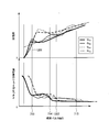
- FIG. 7 is a diagram showing a relationship between an injection amount, a standard deviation ( ⁇ ) of shot variations of the injection amount, and an injection pulse width when the fuel injection device is controlled by the drive current waveform of FIG. 6.
- FIG. 1 shows a configuration example of a fuel injection system 1 according to the first embodiment.
- the fuel injection system 1 is an example in which the present invention is applied to a cylinder direct injection engine (an example of an internal combustion engine), but the present invention is not limited to this example.
- the in-cylinder direct injection engine may be simply referred to as “engine”.
- the fuel injection system 1 is composed of four fuel injection devices 101A to 101D and a control device 150, as shown in FIG.
- the in-cylinder direct injection engine according to this embodiment includes four cylinders 108 (engine cylinders).
- the control device 150 is a control device for a vehicle that controls the fuel injection device 101, for example. In the following description, when the fuel injection devices 101A to 101D are not distinguished, they will be referred to as "fuel injection device 101".
- fuel injection devices 101A to 101D are installed so that mist-like fuel is directly injected into the combustion chamber 107 through injection holes 219 (see FIG. 2 described later). ..
- the fuel is boosted by the fuel pump 106, delivered to the fuel pipe 105, and delivered to the fuel injection devices 101A to 101D through the fuel pipe 105.
- a pressure sensor 102 that measures the fuel pressure in the fuel pipe 105 is installed at one end of the fuel pipe 105. The fuel pressure varies depending on the balance between the flow rate of fuel discharged by the fuel pump 106 and the injection amount of fuel injected into each combustion chamber 107 by the fuel injection device 101. Based on the measurement result of the pressure sensor 102, the discharge amount of fuel from the fuel pump 106 is controlled with a predetermined pressure as a target value.
- the fuel injection of the fuel injection devices 101A to 101D is controlled by the pulse width of the injection pulse sent from the engine control unit (ECU) 104 (hereinafter referred to as "injection pulse width"). That is, the injection amount of the injected fuel is determined based on the injection pulse width supplied to the fuel injection device 101.
- the command of the injection pulse width is input to the drive circuit 103 provided for each fuel injection device 101.
- the drive circuit 103 determines the waveform of the drive current (sometimes abbreviated as “current”) based on a command from the ECU 104, and causes the fuel injection device 101 to have the drive current of the above waveform for a time period based on the injection pulse width. To supply.
- the drive circuit 103 may be mounted as a component or a board integrated with the ECU 104. In this embodiment, a device in which the drive circuit 103 and the ECU 104 are integrated is referred to as a control device 150.
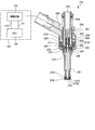
- FIG. 2 shows an example of a vertical cross section of the fuel injection device 101 and a configuration example of the drive circuit 103 and the ECU 104 connected to the fuel injection device 101.
- the ECU 104 takes in signals indicating the state of the engine from various sensors (not shown), and calculates the injection pulse width and the injection timing for controlling the injection amount injected from the fuel injection device 101 according to the operating conditions of the internal combustion engine. To do. Further, the ECU 104 is equipped with an A / D converter and an I / O port for taking in signals from various sensors. The injection pulse output from the ECU 104 is input to the drive circuit 103 through the signal line 110. The drive circuit 103 controls the voltage applied to the solenoid (coil) 205 and supplies a current. The ECU 104 communicates with the drive circuit 103 via the communication line 111. Through the communication line 111, the ECU 104 can switch the drive current generated by the drive circuit 103 according to the pressure of fuel supplied to the fuel injection device 101 and the operating conditions, and can change the set values of the current and time.
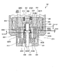
- FIG. 3 is an enlarged cross-sectional view showing an example of the drive unit structure of the fuel injection device 101.
- the relationship between the mover 202, the valve body 214, and the fixed core 207 will be described.
- the fuel injection device 101 shown in FIGS. 2 and 3 is an electromagnetic fuel injection device having a normally closed valve.
- the fuel injection device 101 has a substantially rod-shaped valve body 214 inside, and an orifice cup 216 having a valve seat 218 is provided at a position facing the tip end portion of the valve body 214.
- An injection hole 219 for injecting fuel is formed in the valve seat 218.
- a spring (hereinafter, referred to as “first spring”) 210 that urges the valve body 214 in the valve closing direction (downward direction) is provided above the valve body 214.
- first spring hereinafter, referred to as “first spring”
- a magnetic attraction force acts on the mover 202 to move the mover 202, and the valve body 214 moves in conjunction with the mover 202.
- the solenoid 205 is not energized, the valve body 214 is biased in the valve closing direction by the first spring 210, and the valve body 214 comes into contact with the valve seat 218 to seal the fuel (valve
- a recess 202C is formed on the upper end surface 202A of the mover 202 toward the lower end surface 202B.
- the intermediate member 220 is provided inside the recess 202C.
- the intermediate member 220 is a member located between the movable element 202 and the fixed core 207.
- a recess 220A is formed upward on the lower surface side of the intermediate member 220.
- the recess 220A has a diameter (inner diameter) and a depth in which a stepped portion 329 (collar portion) formed in an annular shape on the outer peripheral surface of the head portion 214A can be accommodated.
- the diameter (inner diameter) of the recess 220A is larger than the diameter (outer diameter) of the stepped portion 329, and the depth dimension of the recess 220A is greater than the dimension between the upper end surface and the lower end surface of the stepped portion 329. large.
- a through hole 220B through which the protrusion 331 of the head 214A penetrates is formed in the bottom (bottom surface 220E) of the recess 220A.
- a spring (hereinafter referred to as “third spring”) 234 is held between the intermediate member 220 and the cap 232.
- the upper end surface 220C of the intermediate member 220 constitutes a spring seat against which one end of the third spring 234 abuts.
- the third spring 234 biases the mover 202 in the valve closing direction from the fixed core 207 side.
- a lid-shaped cap 232 is arranged above the intermediate member 220.
- a flange portion 232A is formed at the upper end of the cap 232 so as to project in the radial direction, and a spring seat with which the other end of the third spring 234 abuts is formed at the lower end surface of the flange portion 232A. ..
- a tubular portion 232B is formed downward on the lower end surface of the collar portion 232A of the cap 232, and the upper portion (head portion 214a) of the valve body 214 is press-fitted and fixed in the tubular portion 232B.
- the cap 232 and the intermediate member 220 respectively form the spring seat of the third spring 234. Therefore, the diameter (inner diameter) of the through hole 220B of the intermediate member 220 is smaller than the diameter (outer diameter) of the collar portion 232A of the cap 232. Further, the diameter (outer diameter) of the tubular portion 232B of the cap 232 is smaller than the inner diameter of the third spring 234.
- the cap 232 receives the biasing force of the first spring 210 from above and the biasing force (set load) of the third spring 234 from below.
- the biasing force of the first spring 210 is larger than the biasing force of the third spring 234, and as a result, the cap 232 has a difference between the biasing force of the first spring 210 and the biasing force of the third spring 234. It is pressed against the protrusion 331 on the upper portion of the valve body 214 by the urging force. No force is applied to the cap 232 in the direction in which the valve body 214 comes off from the protrusion 331 of the valve body 214 (downward in the drawing). Therefore, it suffices to press-fit and fix the cap 232 to the protrusion 331, and it is not necessary to weld it.
- the state of the fuel injection device 101 shown in FIG. 2 is a state in which the valve body 214 receives the biasing force of the first spring 210 and the magnetic attraction force does not act on the mover 202. In this state, the tip end portion 214B (seat portion) of the valve body 214 contacts the valve seat 218, and the fuel injection device 101 is closed and in a stable state.
- the intermediate member 220 receives the biasing force of the third spring 234, and the bottom surface 220E of the recess 220A formed in the intermediate member 220 contacts the upper end surface of the stepped portion 329 of the valve body 214. ing. That is, the size (dimension) of the gap G3 between the bottom surface 220E of the recess 220A formed in the intermediate member 220 and the upper end surface of the stepped portion 329 of the valve body 214 is zero.
- the bottom surface 220E of the recess 220A formed in the intermediate member 220 and the upper end surface of the stepped portion 329 of the valve body 214 respectively form contact surfaces where the intermediate member 220 and the valve body 214 contact each other.
- a zero spring (hereinafter referred to as "second spring") 212 is provided between the lower end surface 202B of the mover 202 and the contact surface 303 formed inside the nozzle holder 201 (large-diameter cylindrical portion 240). Are arranged. Since the mover 202 is biased toward the fixed core 207 by the biasing force of the second spring 212, the bottom surface 202D of the recess 202C formed in the mover 202 is the lower end surface 220D of the intermediate member 220. Abut. The biasing force of the second spring 212 is smaller than the biasing force of the third spring 234. Therefore, the mover 202 cannot push back the intermediate member 220 biased downward by the third spring 234, and moves upward (valve opening direction) by the intermediate member 220 and the third spring 234. Can be stopped.
- the depth dimension of the recess 220A of the intermediate member 220 is larger than the height of the stepped portion 329 of the valve body 214 (dimension between the upper end surface and the lower end surface). Therefore, in the state shown in FIG. 3 (valve closed state), the bottom surface 202D of the recess 202C formed in the mover 202 and the lower end surface of the stepped portion 329 of the valve body 214 are not in contact with each other, and the recess 202C A gap G2 having a size (dimension) D2 is formed between the bottom surface 202D and the lower end surface of the stepped portion 329.
- the size D2 of the gap G2 is the size of the gap G1 between the upper end surface 202A of the mover 202 (the surface facing the fixed core 207) and the lower end surface 207B of the fixed core 207 (the surface facing the mover 202) ( Dimension) smaller than D1 (D2 ⁇ D1).
- the intermediate member 220 is a member that forms a gap G2 having a size of D2 between the mover 202 and the lower end surface of the stepped portion 329 of the valve body 214, and is a gap forming member. You may call.
- the third spring 234 urges the intermediate member (gap forming member) 220 in the valve closing direction (downward direction), and in the valve closed state of FIG. 3, the intermediate member 220 has the stepped portion 329 of the valve body 214. Is positioned on the upper end surface (reference position) of. In this state, the lower end surface 220D of the intermediate member 220 comes into contact with the mover 202, whereby the lower end surface of the stepped portion 329 that is the engaging portion of the valve body 214 and the recess 202C that is the engaging portion of the movable element 202. A gap G2 having a size D2 is formed between the bottom surface 202D and the bottom surface 202D. The intermediate member 220 is positioned on the upper end surface of the stepped portion 329 by the bottom surface 220E of the recess 220A contacting the upper end surface (reference position) of the stepped portion 329 of the valve body 214.
- the spring force (biasing force) of the first spring 210 is the largest.
- the spring force (biasing force) of the third spring 234 is large, and the spring force (biasing force) of the second spring 212 is the smallest.
- the diameter of the through hole formed in the mover 202 is smaller than the diameter of the stepped portion 329 of the valve body 214. Therefore, at the time of the valve opening operation in which the valve body 214 shifts from the closed state to the valve open state, or during the valve closing operation in which the valve body 214 shifts from the valve open state to the valve close state, the lower end surface of the stepped portion 329 of the valve body 214 Engages with the bottom surface 202D of the recess 202C formed in the mover 202, and the mover 202 and the valve body 214 move in cooperation with each other.
- valve body 214 and the mover 202 can move in different directions.
- the operations of the mover 202 and the valve body 214 will be described in detail later.
- the mover 202 is guided to move in the vertical direction (valve opening direction and valve closing direction) by the outer peripheral surface of the movable element 202 contacting the inner peripheral surface of the nozzle holder 201 (housing member). Further, the valve body 214 is guided to move in the vertical direction (valve opening direction and valve closing direction) by its outer peripheral surface being in contact with the inner peripheral surface of the through hole of the mover 202. That is, the inner peripheral surface of the nozzle holder 201 functions as a guide when the mover 202 moves in the axial direction. Further, the inner peripheral surface of the through hole of the mover 202 functions as a guide when the valve body 214 moves in the axial direction.
- a tip portion 214B of the valve body 214 is guided by a guide hole of an annular guide member 215.
- the valve body 214 is guided by the inner peripheral surface of the nozzle holder 201, the through hole of the mover 202, and the guide member 215 so as to reciprocate straight in the axial direction.
- the upper end surface 202A of the mover 202 and the lower end surface 207B of the fixed core 207 are described as abutting, but the present invention is not limited to this example.
- the upper end surface 202A of the mover 202 or the lower end surface 207B of the fixed core 207 is provided with a projection portion or both, and the projection portion and the end surface or the projection portions are in contact with each other. is there.
- the above-mentioned gap G1 is a gap between the contact portion on the side of the mover 202 and the contact portion on the side of the fixed core 207.
- the fixed core 207 is press-fitted into the inner peripheral portion of the large-diameter tubular portion 240 of the nozzle holder 201, and both members are welded and joined at the press-fitting contact position.
- the fixed core 207 is a component that applies a magnetic attraction force to the mover 202 to attract (attract) the mover 202 in the valve opening direction.
- the gap formed between the inside of the large-diameter cylindrical portion 240 of the nozzle holder 201 and the outside air is sealed by welding the fixed core 207.
- the fixed core 207 is provided at its center with a through hole (center hole) having a diameter slightly larger than the diameter of the intermediate member 220 as a fuel passage.
- the head 214A of the valve body 214 and the cap 232 are inserted into the inner periphery of the lower end of the through hole of the fixed core 207 in a non-contact state.
- the lower end of the first spring 210 for initial load setting is in contact with the spring receiving surface formed on the upper end surface of the cap 232 provided near the head 214A of the valve body 214.
- the upper end of the first spring 210 is received by the adjusting pin 224 (see FIG. 1) press-fitted into the through hole of the fixed core 207, so that the first spring 210 is held between the cap 232 and the adjusting pin 224. Has been done.
- the initial load by which the first spring 210 presses the valve body 214 against the valve seat 218 can be adjusted.
- the lower end surface 207B of the fixed core 207 faces the upper end surface 202A of the mover 202 with a magnetic attraction gap (gap G1) of about 40 to 100 ⁇ m. Is configured to. It should be noted that in FIG. 2, the ratio of dimensions is ignored and the display is enlarged.
- a cup-shaped housing 203 is fixed to the outer circumference of the large-diameter cylindrical portion 240 of the nozzle holder 201.
- a through hole 213 is provided at the center of the bottom of the housing 203, and the large diameter tubular portion 240 of the nozzle holder 201 is inserted into the through hole 213.
- An outer peripheral wall portion of the housing 203 forms an outer peripheral yoke portion facing the outer peripheral surface of the large-diameter cylindrical portion 240 of the nozzle holder 201.
- An annular or tubular solenoid 205 is arranged in an annular space formed between the housing 203 and the large-diameter tubular portion 240.
- the solenoid 205 is formed by an annular bobbin 204 having a U-shaped groove having a U-shaped cross section, which is open outward in the radial direction, and a copper wire 206 wound in the groove.
- a rigid conductor 209 is fixed to the winding start end and the winding end end of the solenoid 205.
- the conductor 209, the fixed core 207, and the outer periphery of the large-diameter cylindrical portion 240 of the nozzle holder 201 are molded by injecting an insulating resin from the inner peripheral side of the upper end opening of the housing 203 and covered with a resin molded body.
- An annular magnetic path is formed in the fixed core 207, the mover 202, the large-diameter cylindrical portion 240 of the nozzle holder 201, and the housing (outer peripheral yoke portion) 203 so as to surround the solenoid 205.
- the fuel supplied to the fuel injection device 101 is supplied from the fuel pipe 105 provided upstream of the fuel injection device 101 and flows through the first fuel passage hole 231 to the tip of the valve body 214.
- the seat is formed at the end of the valve body 214 on the valve seat 218 side and the valve seat 218 seals the fuel.
- a pressure difference is generated between the upper portion and the lower portion of the valve body 214 due to the fuel pressure, and the valve body 214 is pushed in the valve closing direction by the fuel pressure and the force corresponding to the pressure receiving surface of the seat portion inner diameter at the valve seat position. Has been done.
- a gap G2 is provided between the contact surfaces of the valve body 214 and the mover 202 (the lower end surface of the stepped portion 329 and the bottom surface 202D of the recess 202C) via the intermediate member 220.
- the mover 202 is arranged axially with the valve body 214 with a gap G2.
- the mover 202 Since the movement of the mover 202 is an idling movement that is performed separately from the valve body 214 that is subjected to the differential pressure due to the fuel pressure, the mover 202 is not affected by the fuel pressure or the like. It is possible to move fast.
- the load of the first spring 210 is configured not to act on the valve body 214, so that the valve body 214 can move at high speed.
- the mover 202 transmits a force to the valve body 214 through the contact surface (the bottom surface 202D of the recess 202C), and the valve body 214 is opened in the valve opening direction. Pull up. At this time, the mover 202 collides with the valve body 214 in a state of performing a free running motion and having kinetic energy. As a result, the valve body 214 receives the kinetic energy of the mover 202, and starts displacement in the valve opening direction at high speed.
- the valve body 214 is acted upon by a differential pressure that accompanies the fuel pressure.
- the differential pressure acting on the valve body 214 is due to a pressure drop caused by a decrease in static pressure due to the Bernoulli effect when the flow velocity of fuel in the seat section increases in a range where the flow passage cross-sectional area near the seat section of the valve body 214 is small. It occurs when the pressure of the fuel near the tip portion 214B of the valve body 214 decreases.
- the differential pressure acting on the valve body 214 is greatly affected by the flow passage cross-sectional area near the seat portion. Therefore, the differential pressure becomes large under the condition that the displacement amount of the valve body 214 is small, and becomes small under the condition that the displacement amount is large. Therefore, at the timing when the valve body 214 starts to be opened from the closed state, the displacement is small, and the differential pressure becomes large, it becomes difficult to perform the valve opening operation, and the valve opening of the valve body 214 is impacted by the idling motion of the mover 202. Is done in a regular manner. As a result, the fuel injection device 101 can perform the valve opening operation even when a higher fuel pressure is applied.
- the biasing force of the first spring 210 can be set to a stronger force in the fuel pressure range that requires the valve opening operation. By setting the first spring 210 to a stronger force, the time required for the valve closing operation described later can be shortened, which is effective in controlling the minute injection amount.
- the mover 202 collides with the fixed core 207.
- the mover 202 rebounds, but the magnetic attraction force acting on the mover 202 causes the mover 202 to be attracted to the fixed core 207 and eventually stops.
- the second spring 212 exerts a force on the mover 202 in the direction of the fixed core 207, the displacement amount of the rebound can be reduced, and the time until the rebound converges can be shortened. it can.
- the small bouncing action shortens the time during which a gap is generated between the mover 202 and the fixed core 207, and enables stable operation even with a smaller injection pulse width.
- a gap (an example of a space) is formed between the valve body 214 and the valve seat 218, and the fuel is injected from the injection hole 219 into the combustion chamber 107.
- the fuel passes through the center hole (through hole) provided in the fixed core 207, the fuel passage hole provided in the mover 202, and the fuel passage hole provided in the guide member 215, and then flows in the downstream direction (injection). It flows to the hole 219).
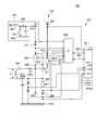
- FIG. 5 is a diagram showing an example of the drive circuit 103 and the ECU 104 of the fuel injection device 101.
- the control device 150 includes a drive circuit 103 and an ECU 104.
- the ECU 104 includes a drive IC (Integrated Circuit) 502 and a CPU (Central Processing Unit) 501 as an arithmetic processing unit.
- the CPU 501 (an example of a control unit) takes in signals indicating the state of the engine output from various sensors such as an A / F sensor, an oxygen sensor, and a crank angle sensor (not shown) in addition to the pressure sensor 102.
- the CPU 501 and the drive IC 502 can be collectively referred to as a control unit.
- the ECU 104 may include the drive circuit 103.
- the pressure sensor 102 is attached to the fuel pipe 105 upstream of the fuel injection device 101 (see FIG. 1).
- the A / F sensor measures the amount of air flowing into the cylinder 108 (engine cylinder).
- the oxygen sensor detects the oxygen concentration of the exhaust gas discharged from the cylinder 108.
- the CPU 501 controls the injection amount of the fuel injected from the fuel injection device 101 according to the operating conditions of the internal combustion engine based on the signals fetched from various sensors and the injection pulse width (injection pulse width Ti) and injection. Perform timing calculation.
- the CPU 501 calculates an appropriate value of the injection pulse width Ti (that is, the injection amount) and an injection timing according to the operating condition of the internal combustion engine, and the injection pulse width Ti to the drive IC 502 of the fuel injection device 101 through the communication line 504. Is output.
- the driving IC 502 switches the energization / non-energization of the switching elements 505, 506, 507 to supply a driving current to the fuel injection device 101 (solenoid 205).
- the switching elements 505, 506, 507 are composed of, for example, FETs or transistors, and can switch between energization / de-energization of the fuel injection device 101.
- the ECU 104 is equipped with a register and a memory 501M (an example of a recording medium) that stores numerical data necessary for controlling the engine such as calculation of the injection pulse width.
- the register and memory 501M is included in the control device 150 or the CPU 501 in the control device 150.
- the memory 501M is arranged outside the CPU 501.
- the memory 501M may store a computer program for the CPU 501 to control driving of the fuel injection device 101.
- the CPU 501 reads out and executes the computer program recorded in the memory 501M to realize all or part of the function of controlling the drive of the fuel injection device 101.
- another arithmetic processing device such as an MPU (Micro Processing Unit) may be used.
- MPU Micro Processing Unit
- the switching element 505 is connected between the booster circuit 514 (high voltage source) that supplies the boosted voltage VH and the high voltage side terminal (power source side terminal 590) of the solenoid 205 of the fuel injection device 101.
- the boosted voltage VH output by the booster circuit 514 is higher than the battery voltage VB supplied to the drive circuit 103 by the battery voltage source 520 (low voltage source).
- the boost voltage VH which is the initial voltage output from the boost circuit 514, is 60 V, and is generated by boosting the battery voltage VB by the boost circuit 514.
- the booster circuit 514 As a method of realizing the booster circuit 514, there are a method of using a DC / DC converter and the like, and a method of using a solenoid 530, a transistor 531, a diode 532, and a capacitor 533 as shown in FIG.
- a method of using a DC / DC converter and the like As a method of realizing the booster circuit 514, there are a method of using a DC / DC converter and the like, and a method of using a solenoid 530, a transistor 531, a diode 532, and a capacitor 533 as shown in FIG.
- the transistor 531 when the transistor 531 is turned on, the current due to the battery voltage VB flows to the ground potential 534 side via the solenoid 530.
- the transistor 531 when the transistor 531 is turned off, the high voltage generated in the solenoid 530 is rectified through the diode 532, and the charge is stored in the capacitor 533.
- the voltage of the capacitor 533 can be increased to the boost voltage VH.
- the transistor 531 is connected to the drive IC 502 or the CPU 501 and is configured so that the boosted voltage VH output from the booster circuit 514 can be detected by the drive IC 502 or the CPU 501.
- a diode 535 is provided between the power source side terminal 590 of the solenoid 205 and the switching element 505 so that a current flows from the booster circuit 514 (high voltage source) toward the solenoid 205 and the ground potential 515. ..
- a diode 511 is also provided between the power source side terminal 590 of the solenoid 205 and the switching element 507 so that a current flows from the battery voltage source 520 (low voltage source) toward the solenoid 205 and the ground potential 515. There is. While the switching element 506 is energized, no current flows from the ground potential 515 to the solenoid 205, the battery voltage source 520 and the booster circuit 514.
- the switching element 507 is connected between the battery voltage source 520 which is a low voltage source and the power source side terminal 590 of the fuel injection device 101.
- the value of the battery voltage VB output by the battery voltage source 520 is, for example, about 12V to 14V.
- the switching element 506 is connected between the low-voltage side terminal of the fuel injection device 101 and the ground potential 515.
- the drive IC 502 detects the current value flowing in the fuel injection device 101 (each part of the drive circuit 103) by each of the current detection resistors 508, 512, 513.
- the drive circuit 103 switches the energization / non-energization of the switching elements 505, 506, 507 according to the current value detected by the drive IC 502 to generate a desired drive current.
- the diodes 509 and 510 are provided to apply a reverse voltage to the solenoid 205 of the fuel injection device 101 and rapidly reduce the current supplied to the solenoid 205.
- the CPU 501 communicates with the drive IC 502 through the communication line 503, and can switch the drive current generated by the drive IC 502 according to the pressure of fuel supplied to the fuel injection device 101 and the operating conditions. Further, both ends of the resistors 508, 512, 513 are connected to the A / D conversion port of the driving IC 502, and the driving IC 502 is configured to detect the voltage applied across the resistors 508, 512, 513.
- FIG. 4 is a timing chart showing a general injection pulse for driving the fuel injection device 101, a drive voltage and a drive current supplied to the fuel injection device 101, a displacement amount of the valve element 214 and the mover 202, and time. Is.
- the drive circuit 103 When the ejection pulse is input to the drive circuit 103, the drive circuit 103 energizes the switching elements 505 and 506 according to the pulse width. As a result, the drive circuit 103 applies the high voltage 401 to the solenoid 205 with the boosted voltage VH boosted to a voltage higher than the battery voltage VB, and starts supplying the drive current to the solenoid 205. The drive circuit 103 stops the application of the high voltage 401 when the current value of the current supplied to the solenoid 205 reaches the maximum drive current I peak (hereinafter referred to as “maximum current”) that is predetermined in the ECU 104.
- maximum current the maximum drive current I peak
- the switching element 506 When the switching element 506 is turned on and the switching elements 505 and 507 are de-energized during the transition period from the maximum current I peak to the predetermined current 403, the voltage of almost 0 V is applied to the solenoid 205.
- the current supplied to the solenoid 205 flows through the fuel injection device 101, the switching element 506, the resistor 508, the ground potential 515, and the fuel injection device 101, whereby the current flowing through the solenoid 205 is gradually reduced.
- the current supplied to the solenoid 205 can be secured by gently reducing the current flowing through the solenoid 205. Therefore, even when the fuel pressure supplied to the fuel injection device 101 increases, the fuel injection device 101 can stably perform the valve opening operation until the mover 202 and the valve body 214 reach the maximum height position.
- the current 403 is a holding current for holding the mover 202 at the maximum height position.
- the switching elements 505, 506, 507 are turned off during the transition period from the maximum current I peak to the current 403, the diode 509 and the diode 510 are energized by the counter electromotive force due to the inductance of the fuel injection device 101.
- the diodes 509 and 510 are energized, the current of the solenoid 205 is returned to the booster circuit 514 side, and the current supplied to the fuel injection device 101 rapidly decreases from the maximum current I peak like the current 402.
- the time required for the current flowing through the solenoid 205 to reach the level of the current 403 is shortened. Therefore, when the switching elements 505, 506, and 507 are turned off, there is an effect of accelerating the time until the magnetic attraction force becomes constant after a certain delay time after the current flowing through the solenoid 205 reaches the current 403.
- the drive circuit 103 energizes the switching element 506.
- the switching element 507 is energized / de-energized.
- the battery voltage VB is applied to the solenoid 205 and the level of the current 403 is maintained.
- a switching period is provided to control such that the predetermined current 403 is maintained.
- the fluid force acting on the valve body 214 increases, and the time until the valve body 214 reaches the target opening degree increases due to the fluid resistance. As a result, the arrival timing of the target opening may be delayed with respect to the arrival time of the set maximum current I peak .
- the current of the solenoid 205 is rapidly reduced, the magnetic attraction force acting on the mover 202 is also rapidly reduced, and the behavior of the valve body 214 becomes unstable. It may happen.
- the switching element 506 is energized to gradually decrease the current during the transition of the maximum current I peak from the current 403, the magnetic attraction force can be suppressed from being lowered, and the stability of the valve body 214 at high fuel pressure can be secured. effective.
- the fuel injection device 101 is driven by the profile of the drive current supplied to the solenoid 205.
- the movable element 202 collides with the fixed core 207, performing a bound operation between the mover 202 and the fixed core 207.
- the valve body 214 is configured to be capable of relative displacement with respect to the mover 202. Therefore, the valve body 214 separates from the mover 202, and the displacement of the valve body 214 overshoots beyond the maximum height position. That is, the lower end surface of the stepped portion 329 of the valve body 214 is separated from the bottom surface 202D of the recess 202C formed in the mover 202.
- the mover 202 is stopped at a predetermined maximum height position by the magnetic attraction force generated by the current 403 and the force of the second spring 212 in the valve opening direction, and the valve body 214 is seated on the mover 202. Then, the vehicle stands still at the position corresponding to the maximum height position and the valve is opened (timing t 45 ).
- the displacement amount of the valve body 214 does not become larger than the maximum height position, and the maximum height position is reached after reaching the maximum height position.
- the mover 202 and the valve body 214 have the same displacement amount.
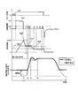
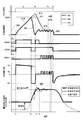
- FIG. 6 shows the injection pulse, the drive current supplied to the fuel injection device 101, the operation timing of the switching element of the fuel injection device 101, the voltage Vinj between the terminals of the solenoid 205, and the valve element 214 according to the first embodiment of the present invention.
- 3 is a timing chart showing the relationship between the amount of displacement of the movable element 202 and time, and time.
- the drive current, the behavior of the switching element, the terminal voltage V inj , and the displacement amount of the valve body 214 when the first current waveform 601 is used are indicated by thick lines, and the second current waveform 602 is used.
- the driving current, the behavior of the switching element, the terminal voltage V inj , and the displacement amount of the valve body 214 are indicated by thin lines.
- the amount of displacement of the mover 202 when the second current waveform 602 is used is indicated by the dotted line. Further, the switching element is described as "SW".
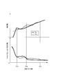
- FIG. 7 shows the relationship between the injection amount, the standard deviation ( ⁇ ) of shot variations of the injection amount, and the injection pulse width when the fuel injection device 101 is controlled with the drive current waveform of FIG. Note that, in FIG. 7, the injection amount characteristic when the fuel injection device 101 is controlled using the first current waveform 601 is shown by a thick line Q701, and the injection amount characteristic when controlled using the second current waveform 602. Is indicated by a thin line Q702.
- the drive IC 502 switches the energization / non-energization of the switching element 507, and controls the current so as to maintain the current value at the current value 604 or in the vicinity thereof.
- the period during which the current is controlled to have the current value 604 is referred to as a first current holding period 655.
- the time to reach the timing t 63 is a value obtained by adding a value preset by the ECU 104 to the value of the current 612, such as reaching the value obtained by adding the zero comma number ampere from the value of the current 612 (holding current). Use it to decide.
- the CPU 501 causes the solenoid 205 to supply a current having a current value higher than the current value 604 that can hold the valve body 214 at the maximum height position. It is better to control so that it is supplied to.
- the current value of the current is higher than the current value 604 in the section from the timing t 66 to the timing t 64 .
- the behavior of the valve body 214 before reaching the maximum height position is stabilized, and the variation in the displacement of the valve body 214 for each shot is increased. Suppressed. This makes it possible to reduce the shot variation ⁇ of the injection amount after the injection pulse width 713 (see FIG. 7) when the valve body 214 reaches the maximum height position.
- the CPU 501 controls the voltage applied to the solenoid 205 so that the drive current having the first current waveform 601 is supplied to the solenoid 205, as indicated by the thick line in FIG. 6.
- the first current waveform 601 is such that the maximum current I peak reaches before the mover 202 collides with the fixed core 207, and the current decreases from the maximum current I peak before the mover 202 collides with the fixed core 207. It has a nice waveform.
- the mover 202 starts to displace in the direction of the fixed core 207, and the switching element 505, at a timing t 66 when the mover 202 is sufficiently accelerated. Turn off 506 and 507.
- the counter electromotive force generated in the solenoid 205 of the fuel injection device 101 energizes the diode 509 and the diode 510.
- the current is returned to the booster circuit 514 side, and the current supplied to the fuel injection device 101 rapidly decreases from the maximum current I peak like the current 651.
- a voltage (-VH) having a magnitude corresponding to the boosted voltage VH and a reverse polarity is generated.
- the bound that occurs between the mover 202, the fixed core 207, and the valve body 214 becomes small, and the timing at which the bound of the valve body 214 converges is advanced to timing t 68 .
- the second current waveform 602 is used as the shot variation ⁇ of the injection amount after the injection pulse width 714 (see FIG. 7) after a certain time has elapsed since the valve body 214 reached the maximum height position. It can be smaller than the case.
- the speed at which the mover 202 collides with the fixed core 207 becomes smaller, so that there is also an effect that the driving sound generated from the fuel injection device 101 can be reduced as compared with the second current waveform 602. ..
- the valve body 214 has the maximum height.
- the behavior until reaching the position may become unstable.
- the shot variation in the injection amount under the condition that the injection pulse width is smaller than the injection pulse width 714 may be larger than that when the second current waveform 602 is used.
- the injection is performed before the valve body 214 contacts the valve seat 218 again after the valve body 214 is separated from the valve seat 218, which is calculated by the CPU 501 of the control device 150.
- the current control for the solenoid 205 is switched based on the fuel injection amount (the injection pulse width for injecting the injection amount).
- the CPU 501 moves the mover 202 to the fixed core until the mover 202 collides with the fixed core 207.
- the second current control based on the second current waveform 602 is performed on the solenoid 205 so that a current larger than the current 612 (holding current) that can be held in contact with the 207 flows to the solenoid 205.
- the CPU 501 changes the voltage applied to the solenoid 205 before the mover 202 collides with the fixed core 207. By switching the polarity of the voltage applied before the child 202 collides with the fixed core 207, the solenoid 205 performs the first current control with the first current waveform 601.
- the current control for the solenoid 205 is performed by switching between the first current waveform and the second current waveform according to the injection amount (injection pulse width) of the fuel injected in the valve open state.
- injection amount injection pulse width
- the current control for the solenoid 205 is performed by switching between the first current waveform and the second current waveform according to the injection amount (injection pulse width) of the fuel injected in the valve open state.
- the CPU 501 of the control device 150 lowers the voltage applied to the solenoid 205 after the mover 202 collides with the fixed core 207 to the set voltage at which the holding current (current 612) flows, thereby making the second current waveform 602.
- the used second current control may be performed.
- the valve body 214 can stably reach the maximum height position.
- the polarity of the set voltage in the second current control is the same as the polarity of the voltage before it has the opposite polarity in the first current control by the first current waveform 601. (In FIG. 6, positive polarity).
- the valve body 214 can stably reach the maximum height position. Therefore, in the second current waveform 602, the timing of stopping the maximum current I peak is not necessarily after the valve body 214 reaches the maximum height position, but before the valve body 214 reaches the maximum height position. You may set it.
- the second current waveform 602 when the injection pulse width is larger than the injection pulse width 715 such that the bound of the valve body 214 is sufficiently converged at the timing when the injection pulse is stopped,
- the shot variation in the injection amount may be the same regardless of which of the current waveform 601 and the second current waveform 602 is used.
- the CPU 501 when the fuel pressure of the fuel pipe 105 that supplies fuel to the fuel injection device 101 is high, the CPU 501 causes the valve body 214 to stably reach the maximum height position, so that the second current waveform 602. To use.
- the CPU 501 uses the first current waveform 601.
- the CPU 501 may perform control so as to switch the current waveform of the drive current according to the operating conditions when there is an instruction of an injection pulse width larger than the preset injection pulse width 715.
- the boosted voltage VH may be applied to the solenoid 205. While the valve body 214 is displaced, the current cannot be increased due to the counter electromotive force associated with the displacement of the mover 202. Therefore, by increasing the applied voltage, the current can surely reach the current 612 (holding current), and the valve body 214 can be stably held in the valve open state.
- the current waveform that can reduce shot variation of the injection amount is appropriately set according to the injection amount (or injection pulse width). This makes it possible to suppress shot variation in the injection amount from the small injection amount to the large injection amount, that is, from the low engine load region to the high load region.
- the present embodiment is suitable for application to fuel injection control of an internal combustion engine that requires a high accuracy of the injection amount, such as when the injection amount in the combustion cycle is minute.
- the switching element 505, 506, and 507 are all deenergized. Then, due to the counter electromotive force due to the inductance of the fuel injection device 101, the diode 509 and the diode 510 are energized, the current is fed back to the booster circuit 514 side, and the current supplied to the fuel injection device 101 becomes like the current 652. It drops rapidly and reaches 0A. Then, when the supply of the current is stopped, the magnetic attraction force acting on the mover 202 is reduced, and the valve opening, which is the resultant force of the magnetic attraction force, the load of the second spring 212, and the inertial force of the mover 202.
- valve body 214 closes the valve from a position lower than the maximum height position. To start. Then, the valve body 214 comes into contact with the valve seat 218 at the timing t 64 , and the fuel injection is stopped.
- the voltage applied to the solenoid 205 before the mover 202 collides with the fixed core 207 has a positive polarity. However, it may have a negative polarity.
- the polarity of the voltage applied to the solenoid 205 may be reversed before and after the mover 202 collides with the fixed core 207.
- the polarity of the voltage applied before the mover 202 collides with the fixed core 207 may be appropriately selected according to the displacement directions of the mover 202 and the valve body 214 and the configuration of the drive circuit 103.
- the displacement directions of the mover 202 and the valve body 214, the configuration of the drive circuit 103, and the polarity of the applied voltage can be flexibly designed.
- FIG. 8 is a diagram showing the relationship between the voltage across the terminals of the solenoid 205, the drive current supplied to the fuel injection device, and time according to the first modification of the first embodiment of the present invention.
- the maximum current I peak supplied to the solenoid 205 is It could grow.
- the heat generation of the fuel injection device 101 and the ECU 104 increases in proportion to the square of the supply current, so heat generation becomes a problem and the current given to the solenoid 205 may be restricted.
- a current waveform 603 (third current waveform) that maintains I peak (current 613) may be used.
- the CPU 501 controls the voltage applied to the solenoid 205 by turning ON / OFF the switching elements 505 and 507, so that the current waveform 603 reaches the maximum current I peak before the mover 202 collides with the fixed core 207 and moves.
- the shape is such that the maximum current I peak is maintained until after the child 202 collides with the fixed core 207.
- the maximum current I peak is maintained for a predetermined time even after the timing t 64 at which the mover 202 collides with the fixed core 207.
- the voltage application to the solenoid 205 may be realized by repeating the application of the boosted voltage VH and the application of the voltage of 0V.
- the solid line 801 shows the voltage between terminals due to the repetition of the application of the boosted voltage VH and the application of the battery voltage VB, and the solid line 803 shows the drive current at that time.
- the inter-terminal voltage due to the repetition of the application of the boosted voltage VH and the application of the voltage of 0 V is shown by a broken line 802, and the drive current at that time is shown by a broken line 804.
- the repeated application of the boosted voltage VH and the battery voltage VB (solid line 801) causes less variation in the inter-terminal voltage compared to the repeated application of the boosted voltage VH and the 0V voltage (broken line 802).
- the behavior of the valve body 214 becomes stable.
- the second current control using the current waveform 603 suppresses the heat generation of the ECU 104 and suppresses the variation in the displacement of the valve body 214 between shots.
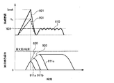
- FIG. 9 is a diagram showing the relationship between the drive current supplied to the fuel injection device 101 according to the second embodiment of the present invention, the amount of displacement of the valve element, and time.
- the valve body 214 When an injection amount smaller than the injection amount when closing the valve after the valve body 214 reaches the maximum height position, the valve body 214 does not reach the maximum height position and the valve is opened in a half lift state.
- Half-lift control for driving the body 214 may be performed.
- the displacement amount of the valve body 214 since the displacement amount of the valve body 214 is not restricted by the stopper (for example, the fixed core 207), the displacement amount of the valve body 214 may fluctuate with a slight change in force. Since the magnetic attraction force is strongly influenced by the magnetic resistance, the smaller the distance between the mover 202 and the fixed core 207, the smaller the magnetic resistance and the greater the magnetic attraction force.
- the magnetic attraction force does not instantaneously become zero due to the influence of the eddy current even if the injection pulse is stopped and the current flowing through the solenoid 205 becomes 0 A, but decreases with time. Therefore, if the magnetic attraction force is too strong, the valve body 214 may reach the maximum height position even if the ECU 104 stops outputting the injection pulse.
- the first current waveform 601 as shown in FIG. 6 is used. It is good to control.
- the CPU 501 applies a reverse voltage to the solenoid 205 after the mover 202 accelerates, and controls the mover 202 to reach the maximum height position by the current 610. This makes it possible to control the injection amount in the half lift state while suppressing a sudden increase in the magnetic attraction force acting on the mover 202.
- the maximum current during the half lift control may be smaller than that in the case of the first current waveform 601.
- a current waveform 901 indicated by a broken line is an example of a current waveform during half lift control.
- the maximum current I HL which is the maximum value, is smaller than the maximum current I peak of the first current waveform 601.
- the displacement gradient 920 of the valve body 214 due to the current waveform 901 is smaller than the displacement gradient 620 of the valve body 214 due to the first current waveform 601. Get smaller. Therefore, it is possible to control the injection amount in the half lift state while suppressing the sudden increase in the magnetic attraction force.
- the displacements 911a, 911b, and 911c respectively represent changes in the displacement amount when the moving direction of the valve body 214 is switched from the valve opening direction to the valve closing direction at each point of the current waveform 901.
- FIG. 10 shows the injection timing and the injection period of the intake stroke and the compression stroke when split injection is performed during one combustion cycle.
- the first injection 1003 is performed in the intake stroke 1001 when the flow in the cylinder 108 is strong, and a large injection is performed. Inject a quantity of fuel. Then, in order to form a rich air-fuel mixture around the spark plug in which fuel is more likely to be ignited than air, a second injection 1004, which is shorter in injection time than the injection 1003 in the compression stroke 1002, is required for one combustion cycle. It is advisable to inject a small amount of fuel. In this specification, the state of the air-fuel mixture containing more fuel than the stoichiometric air-fuel ratio is referred to as “rich”.
- the injection 1004 since the injection 1004 has a smaller injection amount than the injection 1003, the injection 1003 of the intake stroke 1001 is performed with the first current waveform 601 (see FIG. 6) according to the first embodiment, and the compression is performed.
- the injection 1004 of the stroke 1002 is performed with the second current waveform 602 (or the current waveform 603) (see FIG. 6) according to the first embodiment.
- the ignition timing may be retarded (delayed) from the top dead center to increase the exhaust loss, thereby controlling the temperature of the catalyst to be increased.
- retarding the ignition timing combustion becomes unstable. Therefore, fuel is injected in the latter stage of the compression stroke 1002 to form a rich air-fuel mixture around the ignition plug, thereby ensuring combustion stability. Is effective.
- the fuel injected in the compression stroke 1002 is 40% or less of the injection amount blown in one combustion cycle.
- the injection 1003 of the intake stroke 1001 is performed using the first current waveform 601 according to the first embodiment, and the injection of the compression stroke 1002 is performed. This is performed using the second current waveform 602 (or the current waveform 603) according to the first embodiment.
- the CPU 501 of the control device 150 uses the first current control using the first current waveform 601 for the solenoid 205 and the second current waveform 602 (or the current waveform 603) in one combustion cycle.
- the second current control that has been performed may be controlled to be performed at least once.
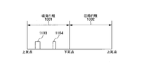
- FIG. 11 shows the injection timing and the injection period of the intake stroke and the compression stroke when split injection is performed during one combustion cycle. 11, the same symbols are used for the same configurations as in FIG.
- the first injection 1103 is performed at a timing when the flow is strong as in the intake stroke 1001, and a large injection amount is injected. To do. Then, at a timing when the flow becomes smaller, the second injection 1104 having a smaller injection amount than the injection 1103 is performed.
- the second and subsequent injections are for fine adjustment of the injection amount, so the injection amount is small. Therefore, since the injection amount of the second injection 1104 is smaller than that of the first injection 1103, the injection 1103 of the intake stroke 1001 is performed using the first current waveform 601 according to the first embodiment. Then, the subsequent injection 1104 is performed using the second current waveform 602 (or the current waveform 603) according to the first embodiment.
- the CPU 501 of the control device 150 may control the solenoid 205 to perform the first current waveform 601 and the second current waveform at least once in one combustion cycle.
- the CPU 501 mounted on the ECU 104 of the control device 150 performs the injection at least twice during the combustion cycle, and the injection amount of the fuel injected from the fuel injection device 101 at one time is determined by the ECU 104.
- the second current waveform 602 (or the current waveform 603) is compared with the number of times of performing the first current control using the first current waveform 601. The current control may be performed so that the number of times the second current control used is performed is larger.
- FIG. 12 shows the relationship between the injection amount, the standard deviation ( ⁇ ) of shot variations in the injection amount, and the injection pulse width according to the fifth embodiment of the present invention.
- the injection amount and the shot variation of the injection amount when the first current waveform 601 is used are indicated by a thick broken line Q101 in the second line.
- the injection amount and shot variation of the injection amount when the current waveform 602 (or the current waveform 603) is used are described by a thin broken line Q102.
- the control device 150 causes the control device 150 to inject fuel that is injected after the valve body 214 separates from the valve seat 218 and before it contacts the valve seat 218 again.
- the amount (injection pulse width) may be set to a larger value as the fuel pressure is higher.
- the CPU 501 sets the injection amount (or the injection amount from the time the valve body 214 opens to the time it closes, which is set to switch between the first current waveform 601 and the second current waveform 602).
- the set value of the injection pulse width is set to increase as the fuel pressure increases.
- the speed of the mover 202 may decrease, and the collision speed when the mover 202 and the fixed core 207 collide may decrease.
- the current should be controlled so that the higher the fuel pressure is, the later the stop timing of the maximum current I peak is delayed. That is, the CPU 501 controls the timing of switching the voltage applied to the solenoid 205 to less than 0 V (reverse polarity) by the first current control such that the higher the fuel pressure, the later the timing.
- the above-described embodiment is a detailed and specific description of the configurations of the fuel injection system 1 and the control device 150 in order to explain the present invention in an easy-to-understand manner. Not limited. Further, it is possible to replace a part of the configuration of a certain embodiment with the constituent elements of another embodiment. It is also possible to add the constituent elements of another embodiment to the configuration of one embodiment. In addition, it is possible to add, delete, or replace other components with respect to a part of the configuration of each embodiment.
- the internal structure of the fuel injection device 101 is configured such that the mover 202 attracted by the magnetic attraction force collides with the fixed core 207, but the invention is not limited to this configuration.
- the fixed core 207 is an example of a fixed portion.
- the fuel injection device 101 may be configured without using the intermediate member 220 (gap forming member).
- the current waveform of the drive current supplied to the solenoid 205 is appropriately set according to the injection amount (or injection pulse width). As a result, it is possible to obtain the effect of suppressing shot variation in the injection amount.
- each of the above-mentioned configurations, functions, processing units, etc. may be realized in hardware by designing a part or all of them with, for example, an integrated circuit.
- each of the above-described components, functions, and the like may be realized by software by a processor interpreting and executing a program that realizes each function.
- Information such as programs, tables, and files that realize each function can be stored in a recording device such as a semiconductor memory, a hard disk, an SSD (Solid State Drive), or a recording medium that uses magnetism or light.
- control lines and information lines are shown to be necessary for explanation, and not all the control lines and information lines are shown on the product. In practice, it may be considered that almost all the components are connected to each other.
Landscapes
- Engineering & Computer Science (AREA)
- Chemical & Material Sciences (AREA)
- Combustion & Propulsion (AREA)
- Mechanical Engineering (AREA)
- General Engineering & Computer Science (AREA)
- Physics & Mathematics (AREA)
- Electromagnetism (AREA)
- Fuel-Injection Apparatus (AREA)
- Electrical Control Of Air Or Fuel Supplied To Internal-Combustion Engine (AREA)
- Magnetically Actuated Valves (AREA)
Abstract
燃料噴射装置の噴射量のショットばらつきを低減する。そのため本発明の一態様の制御装置は、燃料噴射装置の弁体が開弁してから閉弁するまでの燃料の噴射量が設定値以上である場合には、可動子又は弁体が固定部に衝突する前にソレノイドに逆電圧を印加することで、ソレノイドに対し第1の電流波形による第1の電流制御を行う。また、制御装置は、弁体が開弁してから閉弁するまでの燃料の噴射量が設定値未満である場合には、可動子又は弁体が固定部に衝突するまでは、可動子又は弁体を固定部に接触した状態で保持可能な保持電流よりも大きな電流がソレノイドに流れるように、ソレノイドに対し第2の電流波形による第2の電流制御を行う。
Description
本発明は、内燃機関の燃料噴射装置を駆動する車両用の制御装置、及び車両用の燃料噴射制御方法、及び車両用の燃料噴射制御プログラムに関する。
近年、排気規制の強化や環境保護の観点から、エンジンでは、理論空燃比よりも燃料が希薄(リーン)な状態で燃焼させる希薄燃焼が求められている。希薄燃焼では、燃料が希薄の状態のため燃焼の速度が緩慢になり、燃焼が不安定となることで、エンジン筒内の圧力がサイクルごとに変動し、これが希薄燃焼の限界となる場合があった。したがって希薄燃焼では、サイクルごとの変動を抑えるため、燃料噴射装置から噴射される燃料(噴射量)の噴射ごとのばらつきを抑制することが求められる。
一般に、燃料噴射装置の噴射量は、エンジンコントロールユニット(Engine Control Unit:ECU)より出力される噴射パルスのパルス幅によって制御される。通常時閉弁型の電磁式燃料噴射装置は、閉弁方向に力を発生する付勢手段と、ソレノイドと固定コアと可動子で構成される駆動部とから構成される。駆動部においてソレノイドに電流を供給することによって、固定コアと可動子との間に磁気吸引力が発生し、磁気吸引力が閉弁方向の付勢力を超えた時点で可動子が開弁方向に移動する。そして、可動子が弁体に衝突したタイミングで、弁体が弁座から離脱し開弁を開始する。その後、ソレノイドへの電流供給を停止することによって、固定コアと可動子間に発生していた磁気吸引力が低下し、磁気吸引力が閉弁方向の付勢力よりも小さくなった時点で閉弁を開始する。
また一般的に、電磁式燃料噴射装置の駆動回路は、閉弁状態から素早く開弁状態へ移行させるために、ECUから噴射パルスが出力されると最初に高電圧源から高電圧をソレノイドに印加して、ソレノイドの電流を急速に立ち上げる制御を行う。その後、弁体が弁座と離間し固定コアの方向へ移動した後、駆動回路は、印加電圧を低電圧に切替えてソレノイドに一定の電流が供給されるようにスイッチング制御する。
燃料噴射装置の噴射量は、弁体の変位量の積分値で決まるため、噴射ごとのばらつき(ショットばらつき)を抑制するためには、ショットごとの弁体の運動を同一に保つ必要がある。
例えば、噴射量のばらつきを抑制する制御方法として、特許文献1に開示されている方法がある。特許文献1には、燃料噴射弁ごとの開弁応答遅れ時間及び/又は閉弁応答遅れ時間の情報に基づいて、複数の燃料噴射弁から基準となる燃料噴射弁を選定し、選定された燃料噴射弁の噴射量に合わせるように、他の燃料噴射弁の駆動パルス幅を補正する方法が開示されている。
特許文献1に開示された技術は、各気筒に燃料を供給する燃料噴射弁ごとに駆動パルス幅を補正し、気筒ごとに供給される噴射量の相対的なばらつきを抑えることを目的としている。しかし、特許文献1に開示された技術は、燃料噴射弁(弁体)の噴射量のショットばらつきを低減することについては言及していない。
本発明は、このような点に鑑みてなされたものであり、本発明の目的は、弁体のショットごとの変位のばらつきを抑制し、噴射量のショットばらつきを低減することにある。
本発明の一態様の車両用の制御装置は、弁座に接離する弁体と、この弁体を駆動させる可動子と、弁座と弁体との間に燃料を導入する空間を形成するように可動子を吸引する磁気吸引力を生じさせるソレノイドと、磁気吸引力により可動子を吸引する固定コアと、を有する燃料噴射装置を制御する車両用の制御装置である。この車両用の制御装置は、ソレノイドに供給する電流の制御を行う制御部を備える。
上記制御部は、弁体が弁座から離間した後、再び弁座に接触するまでの間に噴射される燃料の噴射量が設定値以上である場合には、可動子又は弁体が固定部に衝突する前にソレノイドに印加する電圧を、当該可動子又は弁体が固定部に衝突する前までに印加していた電圧の極性とは逆極性に切り替えることで、ソレノイドに対し第1の電流波形による第1の電流制御を行う。
また、上記制御部は、弁体が弁座から離間した後、再び弁座に接触するまでの間に噴射される燃料の噴射量が設定値未満である場合には、可動子又は弁体が固定部に衝突するまでは、当該可動子又は弁体を固定部に接触した状態で保持可能な保持電流よりも大きな電流がソレノイドに流れるように、ソレノイドに対し第2の電流波形による第2の電流制御を行う。
本発明によれば、小さい噴射量から大きい噴射量までの範囲において、弁体のショットごとの変位のばらつきを抑制し、噴射量のショットばらつきを低減することができる。
上記した以外の課題、構成及び効果は、以下の実施形態の説明により明らかにされる。
上記した以外の課題、構成及び効果は、以下の実施形態の説明により明らかにされる。
以下、本発明を実施するための形態(以下、「実施形態」と記述する)の例について、添付図面を参照して説明する。本明細書及び添付図面において実質的に同一の機能又は構成を有する構成要素については、同一の符号を付して重複する説明を省略する。
<第1の実施形態>[燃料噴射システムの構成]
以下、図1~図7を用いて、本発明の第1の実施形態に係る燃料噴射システムの構成について説明する。
以下、図1~図7を用いて、本発明の第1の実施形態に係る燃料噴射システムの構成について説明する。
始めに、図1を用いて、第1の実施形態に係る燃料噴射システムの概略を説明する。図1は、第1の実施形態に係る燃料噴射システム1の構成例を示す。燃料噴射システム1は本発明を筒内直接噴射式エンジン(内燃機関の一例)に適用した例であるが、本発明はこの例に限らない。本明細書において、筒内直接噴射式エンジンを単に「エンジン」と称することがある。
燃料噴射システム1は、図1に示すように、4つの燃料噴射装置101A~101D、及び制御装置150とで構成される。本実施形態に係る筒内直接噴射式エンジンは、4つの気筒108(エンジンシリンダ)を備える。制御装置150は、例えば燃料噴射装置101を制御する車両用の制御装置である。以下の説明において、燃料噴射装置101A乃至101Dを区別しない場合には、「燃料噴射装置101」と称する。
燃料噴射システム1の各気筒108には、燃料噴射装置101A~101Dが、その噴射孔219(後述する図2参照)から霧状の燃料が燃焼室107に直接噴射されるように設置されている。燃料は、燃料ポンプ106によって昇圧されて燃料配管105に送出され、燃料配管105を通じて燃料噴射装置101A乃至101Dに配送される。燃料配管105の一端部には、燃料配管105内の燃料圧力を測定する圧力センサ102が設置されている。燃料圧力は、燃料ポンプ106によって吐出された燃料の流量と、燃料噴射装置101によって各燃焼室107内に噴射された燃料の噴射量とのバランスによって変動する。圧力センサ102の測定結果に基づいて、所定の圧力を目標値として燃料ポンプ106からの燃料の吐出量が制御される。
燃料噴射装置101A乃至101Dの燃料の噴射は、エンジンコントロールユニット(ECU)104から送出される噴射パルスのパルス幅(以下「噴射パルス幅」と称する。)によって制御されている。すなわち、噴射される燃料の噴射量は、燃料噴射装置101に供給される噴射パルス幅に基づいて決定される。この噴射パルス幅の指令が、燃料噴射装置101ごとに設けられた駆動回路103に入力される。駆動回路103は、ECU104からの指令に基づいて駆動電流(「電流」と略称することがある。)の波形を決定し、上記噴射パルス幅に基づく時間だけ燃料噴射装置101に上記波形の駆動電流を供給する。なお、駆動回路103は、ECU104と一体の部品や基板として実装されている場合もある。本実施形態では、駆動回路103とECU104が一体となった装置を制御装置150と称する。
次に、燃料噴射装置101及び制御装置150の構成と基本的な動作を説明する。図2は、燃料噴射装置101の縦断面の例と、燃料噴射装置101に接続される駆動回路103及びECU104の構成例を示す。
ECU104は、エンジンの状態を示す信号を各種センサ(図示略)から取り込み、内燃機関の運転条件に応じて燃料噴射装置101から噴射する噴射量を制御するための噴射パルス幅や噴射タイミングの演算を行う。また、ECU104には、各種センサからの信号を取り込むためのA/D変換器とI/Oポートが備えられている。ECU104より出力された噴射パルスは、信号線110を通して駆動回路103に入力される。駆動回路103は、ソレノイド(コイル)205に印加する電圧を制御し、電流を供給する。ECU104は、通信ライン111を介して駆動回路103と通信を行っている。ECU104は、通信ライン111を通じて、燃料噴射装置101に供給する燃料の圧力や運転条件によって駆動回路103で生成する駆動電流を切替えることや、電流及び時間の設定値を変更することが可能である。
次に、図2の燃料噴射装置101の縦断面と図3を用いて、燃料噴射装置101の構成と動作について説明する。図3は、燃料噴射装置101の駆動部構造の例を示した拡大断面図である。特に、可動子202、弁体214、及び固定コア207の関係について説明する。
図2及び図3に示した燃料噴射装置101は、通常時閉弁型の電磁弁を備える電磁式燃料噴射装置である。燃料噴射装置101は、内部に略棒状の弁体214を有し、弁体214の先端部と対向する位置には、弁座218が形成されたオリフィスカップ216が設けられている。弁座218には、燃料を噴射する噴射孔219が形成されている。弁体214の上方には、弁体214を閉弁方向(下方向)に付勢するスプリング(以下「第1のばね」と称する。)210が設けられている。ソレノイド205が通電されると、可動子202に磁気吸引力が作用して可動子202が移動し、可動子202と連動して弁体214が移動する。ソレノイド205が通電されていないときには、弁体214は第1のばね210によって閉弁方向に付勢され、弁体214は弁座218と接触して燃料をシールする構造(閉弁状態)となっている。
可動子202の上端面202Aには、下端面202B側に向けて凹部202Cが形成されている。この凹部202Cの内側に、中間部材220が設けられている。中間部材220は、可動子202と固定コア207の中間に位置する部材である。中間部材220の下面側には、上方に向けて凹部220Aが形成されている。この凹部220Aは、頭部214A外周面に環状に形成された段付き部329(鍔部)が収まる直径(内径)と深さを有している。すなわち、凹部220Aの直径(内径)は、段付き部329の直径(外径)よりも大きく、凹部220Aの深さ寸法は、段付き部329の上端面と下端面との間の寸法よりも大きい。凹部220Aの底部(底面220E)には、頭部214Aの突起部331が貫通する貫通孔220Bが形成されている。
中間部材220とキャップ232との間には、スプリング(以下「第3のばね」と称する。)234が保持されている。中間部材220の上端面220Cは、第3のばね234の一端部が当接するばね座を構成する。第3のばね234は、可動子202を固定コア207側から閉弁方向に付勢する。
中間部材220の上方には、蓋状のキャップ232が配置されている。キャップ232の上端部には、径方向に張り出した鍔部232Aが形成されており、その鍔部232Aの下端面に、第3のばね234の他端部が当接するばね座が構成されている。キャップ232の鍔部232Aの下端面には、下方に向かって筒状部232Bが形成されており、筒状部232B内に、弁体214の上部(頭部214a)が圧入固定されている。
このように、キャップ232と中間部材220とがそれぞれ、第3のばね234のばね座を構成する。そのため、中間部材220の貫通孔220Bの直径(内径)は、キャップ232の鍔部232Aの直径(外径)よりも小さい。また、キャップ232の筒状部232Bの直径(外径)は、第3のばね234の内径よりも小さい。
キャップ232は、上方から第1のばね210の付勢力を受け、下方から第3のばね234の付勢力(セット荷重)を受ける。第1のばね210の付勢力は、第3のばね234の付勢力よりも大きく、結果的にキャップ232は、第1のばね210の付勢力と第3のばね234の付勢力との差分の付勢力によって弁体214の上部の突起部331に押し付けられている。キャップ232には、弁体214の突起部331から弁体214が抜ける方向(図中下方向)の力が加わらない。したがって、キャップ232は、突起部331に圧入固定するだけで十分であり、溶接する必要はない。
また、第3のばね234を配置するために、キャップ232の鍔部232Aの下端面と中間部材220の上端面220Cとの間には、ある程度の間隔を設ける必要がある。このため、キャップ232の筒状部232Bの長さを確保することが容易である。
再び、中間部材220について説明する。図2に示した燃料噴射装置101の状態は、弁体214が第1のばね210による付勢力を受け、且つ可動子202に磁気吸引力が作用していない状態である。この状態では、弁体214の先端部214B(シート部)が弁座218に当接し、燃料噴射装置101が閉弁して安定した状態にある。
この閉弁状態では、中間部材220は第3のばね234の付勢力を受けて、中間部材220に形成された凹部220Aの底面220Eが、弁体214の段付き部329の上端面に当接している。すなわち、中間部材220に形成された凹部220Aの底面220Eと、弁体214の段付き部329の上端面との隙間G3の大きさ(寸法)がゼロである。中間部材220に形成された凹部220Aの底面220Eと弁体214の段付き部329の上端面とはそれぞれ、中間部材220と弁体214とが当接する当接面を構成する。
可動子202の下端面202Bとノズルホルダ201(大径筒状部240)の内部に形成された当接面303との間には、ゼロスプリング(以下「第2のばね」と称す。)212が配置されている。可動子202は、第2のばね212の付勢力を受けて固定コア207側に向けて付勢されるため、可動子202に形成された凹部202Cの底面202Dが、中間部材220の下端面220Dに当接する。第2のばね212の付勢力は第3のばね234の付勢力より小さい。そのため、可動子202は、第3のばね234により下方向へ付勢された中間部材220を押し返すことはできず、中間部材220と第3のばね234とにより上方(開弁方向)への動きを止められる。
中間部材220の凹部220Aの深さ寸法は、弁体214の段付き部329の高さ(上端面と下端面との間の寸法)よりも大きい。このため、図3に示す状態(閉弁状態)では、可動子202に形成された凹部202Cの底面202Dと弁体214の段付き部329の下端面とは当接しておらず、凹部202Cの底面202Dと段付き部329の下端面との間に、大きさ(寸法)がD2の隙間G2が形成されている。この隙間G2の大きさD2は、可動子202の上端面202A(固定コア207との対向面)と固定コア207の下端面207B(可動子202との対向面)との隙間G1の大きさ(寸法)D1よりも小さい(D2<D1)。ここで説明したように、中間部材220は、可動子202と弁体214の段付き部329の下端面との間に、D2の大きさの隙間G2を形成する部材であり、間隙形成部材と呼んでもよい。
第3のばね234は、中間部材(間隙形成部材)220を閉弁方向(下方向)に付勢しており、図3の閉弁状態において中間部材220は、弁体214の段付き部329の上端面(基準位置)に位置づけられている。その状態で、中間部材220の下端面220Dが可動子202と当接することにより、弁体214の係合部である段付き部329の下端面と可動子202の係合部である凹部202Cの底面202Dとの間に、大きさD2の隙間G2を形成する。中間部材220は、その凹部220Aの底面220Eが弁体214の段付き部329の上端面(基準位置)と当接することにより、段付き部329の上端面に位置づけられる。
ここで、以上説明した3つのばねの付勢力について改めて説明しておく。第1のばね210と第2のばね212と第3のばね234のうち、第1のばね210のスプリング力(付勢力)が最も大きい。次に第3のばね234のスプリング力(付勢力)が大きく、第2のばね212のスプリング力(付勢力)が最も小さい。
本実施形態では、弁体214の段付き部329の直径よりも可動子202に形成された貫通孔の直径の方が小さい。そのため、弁体214が閉弁状態から開弁状態に移行する開弁動作時、或いは開弁状態から閉弁状態に移行する閉弁動作時においては、弁体214の段付き部329の下端面が可動子202に形成された凹部202Cの底面202Dと係合し、可動子202と弁体214とが協働して動く。しかし、弁体214を上方へ動かす力或いは可動子202を下方へ動かす力が独立して作用した場合、弁体214と可動子202とは別々の方向に動くことができる。可動子202及び弁体214の動作については、後で詳細に説明する。
本実施形態では、可動子202は、その外周面がノズルホルダ201(ハウジング部材)の内周面と接することによって、上下方向(開弁方向及び閉弁方向)の動きを案内されている。さらに、弁体214は、その外周面が可動子202の貫通孔の内周面に接することによって、上下方向(開弁方向及び閉弁方向)の動きを案内されている。つまり、ノズルホルダ201の内周面は、可動子202が軸方向に移動するときのガイドとして機能する。また、可動子202の貫通孔の内周面は、弁体214が軸方向に移動するときのガイドとして機能する。弁体214の先端部214Bは、円環状のガイド部材215のガイド孔によってガイドされている。このように弁体214は、ノズルホルダ201の内周面と可動子202の貫通孔、並びにガイド部材215によって、軸方向に真っ直ぐに往復動するようガイドされている。
なお、本実施形態では、可動子202の上端面202Aと固定コア207の下端面207Bとが当接するものとして説明しているが、この例に限られない。可動子202の上端面202A又は固定コア207の下端面207Bのいずれか一方、或いは両方に突起部が設けられ、突起部と端面とが、或いは突起部同士が当接するように構成される場合もある。この場合、上述した隙間G1は、可動子202側の当接部と固定コア207側の当接部との間の隙間になる。
再び図2に戻って説明する。ノズルホルダ201の大径筒状部240の内周部には固定コア207が圧入され、圧入接触位置で両部材が溶接接合されている。固定コア207は、可動子202に対して磁気吸引力を作用させて、可動子202を開弁方向に吸引する(引きつける)部品である。固定コア207の溶接接合によりノズルホルダ201の大径筒状部240の内部と外気との間に形成される隙間が密閉される。固定コア207は、その中心に中間部材220の直径よりわずかに大きい直径の貫通孔(中心孔)が燃料通路として設けられている。固定コア207の貫通孔の下端部内周には、弁体214の頭部214A及びキャップ232が非接触状態で挿通されている。
弁体214の頭部214A付近に設けられた、キャップ232の上端面に形成されたスプリング受け面には、初期荷重設定用の第1のばね210の下端が当接している。第1のばね210の上端が固定コア207の貫通孔の内部に圧入される調整ピン224(図1参照)で受け止められることで、第1のばね210がキャップ232と調整ピン224の間に保持されている。調整ピン224の固定位置を調整することで、第1のばね210が弁体214を弁座218に押し付ける初期荷重を調整することができる。
第1のばね210の初期荷重が調整された状態で、固定コア207の下端面207Bが可動子202の上端面202Aに対して約40乃至100μm程度の磁気吸引ギャップ(隙間G1)を隔てて対面するように構成されている。なお、図2では寸法の比率を無視して拡大して表示している。
また、ノズルホルダ201の大径筒状部240の外周には、カップ状のハウジング203が固定されている。ハウジング203の底部の中央には貫通孔213が設けられており、その貫通孔213にはノズルホルダ201の大径筒状部240が挿通されている。ハウジング203の外周壁の部分は、ノズルホルダ201の大径筒状部240の外周面に対面する外周ヨーク部を形成している。ハウジング203と大径筒状部240の間に形成される環状空間内には、環状若しくは筒状のソレノイド205が配置されている。
ソレノイド205は、半径方向外側に向かって開口する、断面がU字状の溝を持つ環状のボビン204と、この溝の中に巻きつけられた銅線206とにより形成される。ソレノイド205の巻始め端部及び巻終わり端部には剛性のある導体209が固定されている。この導体209と固定コア207、ノズルホルダ201の大径筒状部240の外周は、ハウジング203の上端開口部の内周側から絶縁樹脂を注入してモールド成形され、樹脂成形体で覆われる。ソレノイド205を囲むようにして、固定コア207、可動子202、ノズルホルダ201の大径筒状部240及びハウジング(外周ヨーク部)203の部分に、環状の磁気通路が形成される。
燃料噴射装置101に供給される燃料は、燃料噴射装置101の上流に設けられた燃料配管105から供給され、第1の燃料通路孔231を通って弁体214の先端まで流れる。弁体214の弁座218側の端部に形成されたシート部と弁座218とで、燃料をシールしている。閉弁状態では、燃料圧力によって弁体214の上部と下部で差圧が生じ、燃料圧力と弁座位置におけるシート部内径の受圧面に応じた力とによって、弁体214が閉弁方向に押されている。また、閉弁状態においては、弁体214と可動子202の互いの当接面(段付き部329の下端面と凹部202Cの底面202D)の間には、中間部材220を介して隙間G2を有している。このように、弁体214が弁座218に着座している状態において、可動子202が弁体214と軸方向に隙間G2を介して配置されることになる。
上記のように構成された燃料噴射装置101の動作について説明する。ソレノイド205に電流が供給されると、磁気回路によって発生する磁界により、固定コア207と可動子202との間に磁束が通過し、可動子202に対して磁気吸引力が作用する。可動子202に作用する磁気吸引力が、第3のばね234による荷重を超えるタイミングで、可動子202が、固定コア207の方向に変位を開始する。このとき、弁体214と弁座218が接触しているため、可動子202の運動は、燃料の流れが無い状態で行われる。この可動子202の運動は、燃料圧力による差圧力を受けている弁体214とは分離して行われる空走運動であるため、可動子202は、燃料の圧力などの影響を受けることがなく、高速に移動することが可能である。
また、気筒108内の燃焼圧が増加した場合であっても燃料の噴射を抑制するため、第1のばね210による荷重を強く設定する必要がある。すなわち閉弁状態において、第1のばね210による荷重が弁体214に作用しないように構成することで、弁体214は高速に移動することが可能となる。
そして、可動子202の変位量が隙間G2の大きさに達すると、可動子202が当接面(凹部202Cの底面202D)を通じて弁体214に力を伝達し、弁体214を開弁方向に引き上げる。このとき、可動子202は、空走運動を行って運動エネルギーを有した状態で弁体214と衝突する。これにより、弁体214は、可動子202の運動エネルギーを受け取り、高速に開弁方向に変位を開始する。
弁体214には、燃料の圧力に伴って生じる差圧力が作用している。弁体214に作用する差圧力は、弁体214のシート部近傍の流路断面積が小さい範囲において、シート部の燃料の流速が増加し、ベルヌーイ効果による静圧低下に伴って生じる圧力降下によって弁体214の先端部214B付近の燃料の圧力が低下することで生じる。
このように、弁体214に作用する差圧力は、シート部近傍の流路断面積の影響を大きく受ける。そのため、弁体214の変位量が小さい条件では、差圧力が大きくなり、変位量が大きい条件では、差圧力が小さくなる。したがって、弁体214が閉弁状態から開弁開始されて変位が小さく、差圧力が大きくなる開弁動作がし難くなるタイミングで、弁体214の開弁が可動子202の空走運動によって衝撃的に行われる。それにより、燃料噴射装置101は、より高い燃料圧力が作用している状態でも開弁動作を行うことができる。また、開弁動作することが必要な燃料圧力範囲に対して、第1のばね210の付勢力をより強い力に設定することができる。第1のばね210をより強い力に設定することで、後述する閉弁動作に要する時間を短縮することができ、微小噴射量の制御に有効である。
弁体214が開弁動作を開始した後、可動子202は固定コア207に衝突する。可動子202が固定コア207に衝突した時には、可動子202は跳ね返る動作をするが、可動子202に作用する磁気吸引力によって可動子202が固定コア207に吸引され、やがて停止する。このとき、可動子202には第2のばね212によって固定コア207の方向に力が作用しているため、跳ね返りの変位量を小さくでき、また、跳ね返りが収束するまでの時間を短縮することができる。跳ね返り動作が小さいことで、可動子202と固定コア207の間にギャップが生じる時間が短くなり、より小さい噴射パルス幅に対しても安定した動作が行えるようになる。
このようにして開弁動作を終えた可動子202及び弁体214は、開弁状態で静止する。開弁状態では、弁体214と弁座218との間には隙間(空間の一例)が生じており、燃料が噴射孔219から燃焼室107に噴射される。燃料は、固定コア207に設けられた中心孔(貫通孔)と、可動子202に設けられた燃料通路孔と、ガイド部材215に設けられた燃料通路孔とを通過して、下流方向(噴射孔219)へ流れてゆくようになっている。
その後、ソレノイド205への通電が断たれると、磁気回路中に生じていた磁束が消滅し、可動子202に対する磁気吸引力も消滅する。可動子202に作用する磁気吸引力が消滅することによって、弁体214は、第1のばね210による荷重と燃料圧力による力によって、弁座218に接触する閉位置に押し戻される。
[制御装置の駆動回路]
次に、図5を用いて、燃料噴射装置101の制御装置150の構成について説明する。
図5は、燃料噴射装置101の駆動回路103及びECU104の例を示した図である。
次に、図5を用いて、燃料噴射装置101の制御装置150の構成について説明する。
図5は、燃料噴射装置101の駆動回路103及びECU104の例を示した図である。
制御装置150は、駆動回路103及びECU104を備える。例えばECU104には、駆動IC(Integrated Circuit)502と、演算処理装置としてCPU(Central Processing Unit)501が内蔵されている。CPU501(制御部の一例)は、圧力センサ102に加え、図示しないA/Fセンサ、酸素センサ、及びクランク角センサ等の各種センサが出力するエンジンの状態を示す信号を取り込む。CPU501と駆動IC502を含めて、制御部と言うこともできる。なお、ECU104が駆動回路103を内包してもよい。
圧力センサ102は、燃料噴射装置101の上流の燃料配管105に取り付けられている(図1参照)。A/Fセンサは、気筒108(エンジンシリンダ)への流入空気量を測定する。酸素センサは、気筒108から排出された排気ガスの酸素濃度を検出する。CPU501は、各種センサから取り込んだ信号に基づいて、内燃機関の運転条件に応じて燃料噴射装置101から噴射する燃料の噴射量を制御するための噴射パルスのパルス幅(噴射パルス幅Ti)や噴射タイミングの演算を行う。
また、CPU501は、内燃機関の運転条件に応じて適切な噴射パルス幅Tiの値(すなわち噴射量)や噴射タイミングの演算を行い、通信ライン504を通して燃料噴射装置101の駆動IC502に噴射パルス幅Tiを出力する。その後、駆動IC502によって、スイッチング素子505,506,507の通電/非通電を切替えて燃料噴射装置101(ソレノイド205)へ駆動電流を供給する。スイッチング素子505,506,507は、例えばFETやトランジスタ等によって構成され、燃料噴射装置101への通電/非通電を切り替えることができる。
ECU104には、噴射パルス幅の演算等のエンジンの制御に必要な数値データを記憶するレジスタ及びメモリ501M(記録媒体の一例)が搭載されている。レジスタ及びメモリ501Mは、制御装置150もしくは制御装置150内のCPU501に内包されている。図5の例では、CPU501の外部にメモリ501Mが配置されている。メモリ501Mには、CPU501が燃料噴射装置101の駆動を制御するためのコンピュータープログラムが格納されていてもよい。この場合、CPU501が、メモリ501Mに記録されたコンピュータープログラムを読み出して実行することにより、燃料噴射装置101の駆動を制御する機能の全部又は一部が実現される。なお、CPU501に代えてMPU(Micro Processing Unit)等の他の演算処理装置を用いてもよい。
スイッチング素子505は、昇圧電圧VHを供給する昇圧回路514(高電圧源)と、燃料噴射装置101のソレノイド205の高電圧側の端子(電源側端子590)との間に接続されている。昇圧回路514が出力する昇圧電圧VHは、バッテリ電圧源520(低電圧源)が駆動回路103に供給するバッテリ電圧VBよりも高い。例えば、昇圧回路514が出力する初期電圧である昇圧電圧VHは60Vであり、バッテリ電圧VBを昇圧回路514によって昇圧することで生成する。
昇圧回路514を実現する方法には、例えばDC/DCコンバータ等により構成する方法と、図5に示すようにソレノイド530、トランジスタ531、ダイオード532及びコンデンサ533で構成する方法がある。後者の昇圧回路514の場合、トランジスタ531をONにすると、バッテリ電圧VBによる電流はソレノイド530を介して接地電位534側へ流れる。一方、トランジスタ531をOFFにすると、ソレノイド530に発生する高い電圧がダイオード532を通して整流され、コンデンサ533に電荷が蓄積される。このトランジスタ531のON/OFFを繰り返すことで、コンデンサ533の電圧を昇圧電圧VHまで増加させることができる。トランジスタ531は、駆動IC502もしくはCPU501と接続され、昇圧回路514から出力される昇圧電圧VHが、駆動IC502もしくはCPU501で検出できるように構成されている。
また、ソレノイド205の電源側端子590とスイッチング素子505との間には、昇圧回路514(高電圧源)から、ソレノイド205及び接地電位515の方向へ電流が流れるようにダイオード535が設けられている。また、ソレノイド205の電源側端子590とスイッチング素子507との間にも、バッテリ電圧源520(低電圧源)から、ソレノイド205及び接地電位515の方向へ電流が流れるようにダイオード511が設けられている。スイッチング素子506が通電している間は、接地電位515から、ソレノイド205、バッテリ電圧源520及び昇圧回路514へ向けては電流が流れない構成となっている。
また、スイッチング素子507は、低電圧源であるバッテリ電圧源520と燃料噴射装置101の電源側端子590との間に接続されている。バッテリ電圧源520が出力するバッテリ電圧VBの値は、例えば12Vから14V程度である。スイッチング素子506は、燃料噴射装置101の低電圧側の端子と接地電位515との間に接続されている。駆動IC502は、電流検出用の抵抗508,512,513の各々により、燃料噴射装置101(駆動回路103の各部)に流れている電流値を検出する。駆動回路103は、駆動IC502が検出した電流値によってスイッチング素子505,506,507の通電/非通電を切替え、所望の駆動電流を生成している。
ダイオード509,510は、燃料噴射装置101のソレノイド205に逆電圧を印加し、ソレノイド205に供給されている電流を急速に低減するために備え付けられている。CPU501は、通信ライン503を通して、駆動IC502と通信を行っており、燃料噴射装置101に供給する燃料の圧力や運転条件によって駆動IC502によって生成する駆動電流を切替えることが可能である。また、抵抗508,512,513の両端は、駆動IC502のA/D変換ポートに接続されており、抵抗508,512,513の両端にかかる電圧を駆動IC502で検出できるように構成されている。
[一般的なタイミングチャート]
次に、図4を参照して、ECU104から出力される噴射パルスと、燃料噴射装置101のソレノイド205の端子両端の駆動電圧と駆動電流(励磁電流)、燃料噴射装置101の弁体214の変位量(弁体挙動)との関係について説明する。図4は、燃料噴射装置101を駆動する一般的な噴射パルス、燃料噴射装置101に供給する駆動電圧及び駆動電流、弁体214及び可動子202の変位量、並びに時間の関係を示したタイミングチャートである。
次に、図4を参照して、ECU104から出力される噴射パルスと、燃料噴射装置101のソレノイド205の端子両端の駆動電圧と駆動電流(励磁電流)、燃料噴射装置101の弁体214の変位量(弁体挙動)との関係について説明する。図4は、燃料噴射装置101を駆動する一般的な噴射パルス、燃料噴射装置101に供給する駆動電圧及び駆動電流、弁体214及び可動子202の変位量、並びに時間の関係を示したタイミングチャートである。
駆動回路103に噴射パルスが入力されると、駆動回路103はそのパルス幅に応じてスイッチング素子505,506を通電する。これにより、駆動回路103は、バッテリ電圧VBよりも高い電圧に昇圧された昇圧電圧VHによりソレノイド205に高電圧401を印加し、ソレノイド205に駆動電流の供給を開始する。駆動回路103は、ソレノイド205に供給される電流の電流値が予めECU104に定められた最大駆動電流Ipeak(以降「最大電流」と称する。)に到達すると、高電圧401の印加を停止する。
最大電流Ipeakから所定の電流403への移行期間にスイッチング素子506をONにし、スイッチング素子505,507を非通電にすると、ソレノイド205にはほぼ電圧0Vが印加される。ソレノイド205に供給される電流が燃料噴射装置101、スイッチング素子506、抵抗508、接地電位515、及び燃料噴射装置101の経路を流れることで、ソレノイド205に流れる電流は緩やかに減少する。ソレノイド205に流れる電流が緩やかに減少することで、ソレノイド205へ供給する電流を確保することができる。そのため、燃料噴射装置101に供給される燃料圧力が増加した場合であっても、燃料噴射装置101は、可動子202及び弁体214が最大高さ位置になるまで安定的に開弁動作できる。
電流403は、可動子202を最大高さ位置に保持するための保持電流である。最大高さ位置は、可動子202が固定コア207と接触する位置(G1=0)である。
逆に、最大電流Ipeakから電流403への移行期間にスイッチング素子505,506,507をOFFにすると、燃料噴射装置101のインダクタンスによる逆起電力によって、ダイオード509とダイオード510が通電する。ダイオード509とダイオード510が通電すると、ソレノイド205の電流が昇圧回路514側へ帰還され、燃料噴射装置101に供給されていた電流は、電流402のように最大電流Ipeakから急速に低下する。その結果、ソレノイド205に流れる電流が電流403のレベルに到達するまでの時間が早くなる。したがって、スイッチング素子505,506,507をOFFにすると、ソレノイド205に流れる電流が電流403に到達してから一定の遅れ時間の後、磁気吸引力が一定となるまでの時間を早める効果がある。
そして、ソレノイド205に流れる電流が、弁体214を最大高さ位置に保持するために必要な電流値404(電流403とほぼ同じレベル)より小さくなると、駆動回路103は、スイッチング素子506を通電するとともに、スイッチング素子507の通電/非通電を行う。それにより、ソレノイド205にバッテリ電圧VBが印加され電流403のレベルが保たれる。このような所定の電流403が保たれるように制御するスイッチング期間が設けられる。
なお、図4では、最大電流Ipeakから電流403への移行期間に、タイミングt46で駆動電流が電流410のレベルに低下した後、電流410が保たれるように制御するスイッチング期間があるが、この電流410を維持するスイッチング期間はなくてもよい。
燃料噴射装置101に供給される燃料圧力が大きくなると、弁体214に作用する流体力が増加し、流体抵抗により弁体214が目標開度に到達するまでの時間が長くなる。この結果、設定された最大電流Ipeakの到達時間に対して目標開度への到達タイミングが遅れる場合がある。しかし、ソレノイド205の電流を急速に低減すると、可動子202に働く磁気吸引力も急速に低下するため、弁体214の挙動が不安定となり、場合によっては通電中にも関わらず閉弁を開始してしまうことがある。最大電流Ipeakから電流403の移行中にスイッチング素子506を通電状態にして電流を緩やかに減少させる場合、磁気吸引力の低下を抑制でき、高燃料圧力での弁体214の安定性を確保できる効果がある。
このようなソレノイド205に供給する駆動電流のプロファイルにより、燃料噴射装置101は駆動される。高電圧401の印加を開始してからソレノイド205の電流が最大電流Ipeakに達するまでの間に、可動子202がタイミングt41で変位を開始し、弁体214がタイミングt42で変位を開始する(G2=0)。その後、可動子202及び弁体214が最大高さ位置(最大リフト位置)に到達する。
可動子202が最大高さ位置に到達したタイミングt43で、可動子202が固定コア207に衝突し、可動子202が固定コア207との間でバウンド動作を行う。弁体214は可動子202に対して相対変位が可能に構成されている。そのため、弁体214は可動子202から離間し、弁体214の変位は、最大高さ位置を越えてオーバーシュートする。すなわち、弁体214の段付き部329の下端面が可動子202に形成された凹部202Cの底面202Dから離れる。
その後、電流403によって生成される磁気吸引力と第2のばね212の開弁方向の力によって、可動子202は所定の最大高さ位置に静止し、また、弁体214は可動子202に着座して最大高さ位置に対応する位置で静止し、開弁状態となる(タイミングt45)。
なお、弁体214と可動子202が一体となっている可動弁を持つ燃料噴射装置の場合、弁体214の変位量は最大高さ位置よりも大きくならず、最大高さ位置に到達後の可動子202と弁体214の変位量は同等となる。
[制御装置の燃料噴射制御方法]
次に、図6及び図7を用いて、第1の実施形態に係る燃料噴射装置101を制御する制御装置150の燃料噴射制御方法について説明する。
次に、図6及び図7を用いて、第1の実施形態に係る燃料噴射装置101を制御する制御装置150の燃料噴射制御方法について説明する。
図6は、本発明の第1の実施形態に係る噴射パルス、燃料噴射装置101に供給する駆動電流、燃料噴射装置101のスイッチング素子の動作タイミング、ソレノイド205の端子間の電圧Vinj、弁体214及び可動子202の変位量、並びに時間の関係を示したタイミングチャートである。図6において、第1の電流波形601を用いた場合の駆動電流、スイッチング素子の挙動、端子間電圧Vinj、弁体214の変位量を太線で示し、また第2の電流波形602を用いた場合の駆動電流、スイッチング素子の挙動、端子間電圧Vinj、弁体214の変位量を細線で示す。なお、第2の電流波形602を用いた場合の可動子202の変位量を点線で示す。また、スイッチング素子を「SW」と記している。
図7は、図6の駆動電流波形で燃料噴射装置101を制御した場合の噴射量とその噴射量のショットばらつきの標準偏差(σ)、及び噴射パルス幅の関係を示す。なお、図7には、燃料噴射装置101を第1の電流波形601を用いて制御した場合の噴射量特性を太線Q701で示し、第2の電流波形602を用いて制御した場合の噴射量特性を細線Q702で示す。
(第2の電流制御)
まず、第2の電流波形602を用いて制御した場合の燃料噴射装置101の動作について説明する。
まず、第2の電流波形602を用いて制御した場合の燃料噴射装置101の動作について説明する。
図6に示すように、タイミングt61において、CPU501より噴射パルス幅Tiの噴射パルスが通信ライン504を通して駆動IC502に入力されると、スイッチング素子505とスイッチング素子506がONとなり、バッテリ電圧VBよりも高い昇圧電圧VHがソレノイド205に印加される。それにより、駆動電流が燃料噴射装置101に供給され、電流が電流610のように急速に立ち上がる。ソレノイド205に電流が供給されると、可動子202と固定コア207との間に磁気吸引力が作用する。開弁方向の力である磁気吸引力と第2のばね212による荷重との合力が、閉弁方向の力である第3のばね234による荷重を超えたタイミングで、可動子202が変位を開始する。その後、可動子202が隙間G2を滑走した後、可動子202が弁体214に衝突する(G2=0になる)。これにより、弁体214の変位(開弁動作)が開始され、燃料噴射装置101から燃料が噴射される。
そして、電流がタイミングt62で最大電流(極大値)に達すると、スイッチング素子506が通電し、スイッチング素子505とスイッチング素子507は非通電となる。このとき、接地電位515、スイッチング素子506、燃料噴射装置101、及び接地電位515の間で電流が回生する、いわゆるフリーホイールの状態になる。このフリーホイールによって、燃料噴射装置101のソレノイド205の両端にはほぼ0Vの電圧が印加され、電流が電流611のように緩やかに減少する。
その後、時間がタイミングt63に到達すると、駆動IC502は、スイッチング素子507の通電/非通電の切替えを行い、電流が電流値604或いはその近傍で電流値を保持するように制御する。なお、電流を電流値604となるように制御する期間を、第1の電流保持期間655と称する。例えばタイミングt63に達する時間は、電流612(保持電流)の値からゼロコンマ数アンペアを加算した値に達するまでというように、電流612の値にECU104で予め設定された値を加算した電流値を用いて決めるとよい。
CPU501は、弁体214が最大高さ位置に到達するタイミングt64(≧t62)までは、弁体214を最大高さ位置で保持可能な電流値604よりも高い電流値の電流をソレノイド205に供給するように制御するとよい。図6の例では、タイミングt66からタイミングt64の区間で、電流の電流値が電流値604よりも高い。
弁体214が最大高さ位置よりも低い高さ位置の条件では、可動子202と固定コア207との間のギャップ(隙間G1)があるため、磁気抵抗が大きくなり、可動子202と固定コア207が接触している場合と比べて、磁気吸引力が低下する。このため、可動子202乃至弁体214が最大高さ位置に到達するまで、電流値604よりも高い電流値の駆動電流をソレノイド205に供給する。これにより、弁体214が安定して最大高さ位置まで到達可能となり、弁体214が最大高さ位置に到達するタイミングが早くなる。
このように、第2の電流波形602を用いた第2の電流制御では、最大高さ位置に到達する前の弁体214の挙動が安定化して、弁体214のショットごとの変位のばらつきが抑制される。これにより、弁体214が最大高さ位置に到達した噴射パルス幅713以降(図7参照)の噴射量のショットばらつきσを、小さくすることができる。
さらに、図6の例では、ソレノイド205に昇圧電圧VHが印加されることにより、電流が第1の電流波形601の最大電流Ipeakを超えて増加していく。このように、ソレノイド205に大きな駆動電流を供給することにより、最大高さ位置に到達する前の弁体214の挙動がさらに安定する。
一方で、可動子202が固定コア207に大きな速度で衝突するため、区間660に示すように可動子202が固定コア207または弁体214との間でバウンドする。その結果、噴射パルス幅713以降も噴射量のショットばらつきσが小さくならないという問題があった。この問題は、図4で示した電流波形でも同様である。すなわち、弁体214が最大高さ位置に到達するまでにソレノイド205に高い電流値の電流を供給した条件で、この問題が生じる場合があった。
(第1の電流制御)
この問題を解決する方法として、第1の電流波形601を用いた第1の電流制御における駆動方法と、噴射量(噴射パルス幅)及び噴射量のショットばらつきとの関係について説明する。CPU501は、図6に太線で示すように、ソレノイド205に第1の電流波形601の駆動電流が供給されるように、ソレノイド205に印加する電圧を制御する。第1の電流波形601は、可動子202が固定コア207に衝突する前に最大電流Ipeakに達し、かつ可動子202が固定コア207に衝突する前に最大電流Ipeakから電流が減少するような波形となっている。
この問題を解決する方法として、第1の電流波形601を用いた第1の電流制御における駆動方法と、噴射量(噴射パルス幅)及び噴射量のショットばらつきとの関係について説明する。CPU501は、図6に太線で示すように、ソレノイド205に第1の電流波形601の駆動電流が供給されるように、ソレノイド205に印加する電圧を制御する。第1の電流波形601は、可動子202が固定コア207に衝突する前に最大電流Ipeakに達し、かつ可動子202が固定コア207に衝突する前に最大電流Ipeakから電流が減少するような波形となっている。
図6に示すように、可動子202が固定コア207に衝突する速度を抑制するため、可動子202が固定コア207の方向に変位を開始し、十分に加速したタイミングt66でスイッチング素子505,506,507をOFFにする。この結果、燃料噴射装置101のソレノイド205に生じる逆起電力によって、ダイオード509とダイオード510が通電する。それにより、電流が昇圧回路514側へ帰還され、燃料噴射装置101に供給されていた電流は、電流651のように最大電流Ipeakから急速に低下する。このときソレノイド205の端子間には、逆起電力として、昇圧電圧VHに相当する大きさで逆極性の電圧(-VH)が生じる。
ソレノイド205に逆電圧を印加して電流を急速に低減すると、渦電流による一定の遅れの後、磁気回路に生じていた磁束が減少し、可動子202に作用していた磁気吸引力が小さくなる。その後、タイミングt67で可動子202及び弁体214が減速し、可動子202が固定コア207に衝突するときの速度が小さくなる。
その結果として、可動子202と固定コア207及び弁体214との間で生じるバウンドが小さくなり、弁体の214のバウンドが収束するタイミングが、タイミングt68まで早まる。これにより、弁体214が最大高さ位置に到達して一定の時間が経過した、噴射パルス幅714以降(図7参照)の噴射量のショットばらつきσを、第2の電流波形602を用いた場合よりも小さくすることができる。また、第1の電流波形601では、可動子202が固定コア207に衝突するときの速度が小さくなるため、第2の電流波形602よりも燃料噴射装置101から生じる駆動音を低減できる効果もある。
一方で、第1の電流波形601を用いた場合は、弁体214が最大高さ位置に到達する前に、可動子202及び弁体214を減速させているため、弁体214が最大高さ位置に到達するまでの挙動が不安定になる場合がある。例えば、噴射パルス幅714よりも噴射パルス幅が小さい条件での噴射量のショットばらつきが、第2の電流波形602を用いた場合に比べて大きくなる場合があった。
そこで、上述したように、第1の実施形態は、制御装置150のCPU501で演算される、弁体214が弁座218から離間した後、再び弁座218に接触するまでの間に噴射される燃料の噴射量(その噴射量を噴射するための噴射パルス幅)に基づいて、ソレノイド205に対する電流制御を切り替える。
すなわち、CPU501は、噴射パルス幅714の噴射量(設定値の例)未満の小さな噴射量を要求された場合には、可動子202が固定コア207に衝突するまでは、可動子202を固定コア207に接触した状態で保持可能な電流612(保持電流)よりも大きな電流がソレノイド205に流れるように、ソレノイド205に対し第2の電流波形602による第2の電流制御を行う。また、CPU501は、噴射パルス幅714の噴射量(設定値)以上の大きな噴射量を要求された場合には、可動子202が固定コア207に衝突する前にソレノイド205に印加する電圧を、可動子202が固定コア207に衝突する前までに印加していた電圧の極性とは逆極性に切り替えることで、ソレノイド205に対し第1の電流波形601による第1の電流制御を行う。
このように、本実施形態では、開弁状態において噴射される燃料の噴射量(噴射パルス幅)に応じて、第1の電流波形と第2の電流波形を切り替えてソレノイド205に対する電流制御を行うことで、小さい噴射量から大きい噴射量までの範囲において、弁体214のショットごとの変位のばらつきを抑制することができる。それにより、燃料噴射装置101の噴射量のショットばらつきを低減することができる。その結果、筒内直接噴射式エンジン等の内燃機関の燃費と排気性能が改善され、経費削減にも繋がる。
さらに、制御装置150のCPU501は、可動子202が固定コア207に衝突した後にソレノイド205に印加する電圧を、保持電流(電流612)が流れる設定電圧に下げることで、第2の電流波形602を用いた第2の電流制御を行うようにしてもよい。このようにソレノイド205に印加する電圧及び電流を制御することで、弁体214を安定的に最大高さ位置に到達させることができる。本実施形態では、図6から理解されるように、第2の電流制御における設定電圧の極性は、第1の電流波形601による第1の電流制御において逆極性となる前の電圧の極性と同じ(図6では正極性)である。
また、可動子202に電流612(保持電流)よりも高い電流を供給すれば、弁体214を安定的に最大高さ位置まで到達させることができる。そのため、第2の電流波形602において、最大電流Ipeakを停止するタイミングは、必ずしも弁体214が最大高さ位置に到達したとき以降ではなく、弁体214が最大高さ位置に到達する前に設定してもよい。
また、第2の電流波形602を用いた場合、噴射パルスを停止するタイミングで弁体214のバウンドが十分に収束しているような、噴射パルス幅715よりも大きな噴射パルス幅では、第1の電流波形601と第2の電流波形602のどちらを使っても噴射量のショットばらつきが同等となることがある。この場合、CPU501は、例えば燃料噴射装置101に燃料を供給する燃料配管105の燃料圧力が高い場合には、弁体214が最大高さ位置に安定的に到達するために第2の電流波形602を用いる。一方、暖気のアイドル条件など、エンジンの回転数が低いため燃料噴射装置101の駆動音を低減したい場合には、CPU501は、第1の電流波形601を用いる。
このように、CPU501は、予め設定された噴射パルス幅715よりも大きな噴射パルス幅の指令があった場合には、運転条件に応じて駆動電流の電流波形を切り替えるように制御するとよい。
なお、第1の電流波形601において、電流が最大電流Ipeak到達後にソレノイド205に逆電圧を印加した後、再び電流を供給する場合、ソレノイド205には昇圧電圧VHを印加するとよい。弁体214が変位している最中は、可動子202の変位に伴う逆起電力によって、電流が増加できない。したがって、印加電圧を大きくすることで、電流を確実に電流612(保持電流)に到達させることができ、弁体214を安定的に開弁状態で保持できる。
上述したように本実施形態は、噴射量(若しくは噴射パルス幅)に応じて、噴射量のショットばらつきを低減できる電流波形を適切に設定する。これにより、小さな噴射量から大きな噴射量まで、すなわちエンジンの負荷が小さい領域から負荷が大きい領域まで全域にわたって噴射量のショットばらつきを抑制できる。
例えば、噴射量のショットばらつきを抑制することで、熱効率を上げるための理論空燃比よりも燃料が希薄な希薄燃焼や排ガスを吸気側に循環させるEGR(Exhaust Gas Recirculation)を用いた場合において、燃焼速度が緩慢になる条件下であっても、噴射ごとに同じ燃焼状態を実現し、燃焼安定性を高めることができる。本実施形態は、燃焼サイクルにおける噴射量が微小である場合など、高い噴射量の精度を求められる内燃機関の燃料噴射制御に適用して好適である。
また、第1の電流波形601及び第2の電流波形602において、タイミングt69で噴射パルスを停止すると、スイッチング素子505,506,507が全て非通電となる。そして、燃料噴射装置101のインダクタンスによる逆起電力によって、ダイオード509とダイオード510が通電し、電流が昇圧回路514側へ帰還され、燃料噴射装置101に供給されていた電流は、電流652のように急速に低下し、0Aに到達する。そして、電流の供給を停止すると、可動子202に作用していた磁気吸引力が低下し、磁気吸引力と第2のばね212による荷重と、可動子202の慣性力との合力である開弁方向の力が、第1のばね210による荷重と弁体214に作用する差圧力とによる閉弁方向の力を下回ったタイミングで、弁体214は最大高さ位置よりも低い位置から、閉弁を開始する。そして、弁体214がタイミングt64で弁座218と接触し、燃料の噴射を停止する。
なお、上述した第1の実施形態では、第1の電流波形601を用いた第1の電流制御において、可動子202が固定コア207に衝突する前にソレノイド205に印加する電圧を正極性としたが、負極性でもよい。以降の各実施形態でも同様である。第1の電流制御では、ソレノイド205に印加する電圧の極性を、可動子202が固定コア207に衝突する前と後で反転させる構成であればよい。可動子202が固定コア207に衝突する前に印加する電圧の極性は、可動子202及び弁体214の変位方向と駆動回路103の構成に応じて、適宜選択すればよい。このように、本発明は、可動子202及び弁体214の変位方向と駆動回路103の構成、及び印加する電圧の極性を、柔軟に設計することができる。
<第1の実施形態の変形例1>
次に、図8を用いて、本発明の第1の実施形態の変形例1について説明する。図8は、本発明の第1の実施形態の変形例1に係るソレノイド205の端子間の電圧、燃料噴射装置に供給する駆動電流、及び時間の関係を示した図である。
次に、図8を用いて、本発明の第1の実施形態の変形例1について説明する。図8は、本発明の第1の実施形態の変形例1に係るソレノイド205の端子間の電圧、燃料噴射装置に供給する駆動電流、及び時間の関係を示した図である。
第1の実施形態における第2の電流波形602を用いた場合、弁体214が最大高さ位置に到達するまで大きな電流値を供給する必要があるため、ソレノイド205に供給する最大電流Ipeakが大きくなることがあった。この場合、燃料噴射装置101及びECU104の発熱は、供給電流の2乗に比例して大きくなるため、発熱が課題となりソレノイド205に与える電流に制約が生じることがある。
これに対し、図8に示すように、第2の電流制御において、駆動電流が最大電流Ipeakに到達した後、昇圧電圧VHの印加とバッテリ電圧VBの印加を繰り返して行うことで、最大電流Ipeak(電流613)を維持する電流波形603(第3の電流波形)を用いるとよい。CPU501が、スイッチング素子505,507のON/OFFによりソレノイド205に印加する電圧を制御することで、電流波形603は、可動子202が固定コア207に衝突する前に最大電流Ipeakに達し、可動子202が固定コア207に衝突した後まで最大電流Ipeakが維持されるような形状となっている。図6では、可動子202が固定コア207に衝突したタイミングt64を過ぎた後でも、所定の時間だけ最大電流Ipeakが維持されている。なお、ソレノイド205への電圧印加は、昇圧電圧VHの印加と0Vの電圧の印加を繰り返すことにより実現してもよい。
図8において、昇圧電圧VHの印加とバッテリ電圧VBの印加との繰り返しによる端子間電圧を実線801で示し、そのときの駆動電流を実線803で示している。また、昇圧電圧VHの印加と0Vの電圧の印加との繰り返しによる端子間電圧を破線802で示し、そのときの駆動電流を破線804で示している。昇圧電圧VHの印加とバッテリ電圧VBの印加の繰り返し(実線801)は、昇圧電圧VHの印加と0Vの電圧の印加との繰り返し(破線802)と比較して端子間電圧の変動が少ないため、弁体214の挙動が安定する。
このように、第2の電流制御において電流波形603を用いることで、最大電流Ipeakの値を大きくしなくても、弁体214が最大高さ位置に到達するまでに必要な電流を確保できる。このため、電流波形603を用いた第2の電流制御により、ECU104の発熱を抑えつつ、弁体214のショットごとの変位のばらつきが抑制される。
<第2の実施形態>
次に、図9を用いて、本発明の第2の実施形態に係る燃料噴射装置101を制御する制御装置150の燃料噴射制御方法について説明する。図9は、本発明の第2の実施形態に係る燃料噴射装置101に供給する駆動電流、弁体の変位量、及び時間との関係を示した図である。
次に、図9を用いて、本発明の第2の実施形態に係る燃料噴射装置101を制御する制御装置150の燃料噴射制御方法について説明する。図9は、本発明の第2の実施形態に係る燃料噴射装置101に供給する駆動電流、弁体の変位量、及び時間との関係を示した図である。
弁体214が最大高さ位置に到達してから閉弁する場合の噴射量よりも小さな噴射量を要求される場合には、弁体214が最大高さ位置に到達しないハーフリフトの状態で弁体214を駆動するハーフリフト制御を行うとよい。しかし、ハーフリフトの状態では、弁体214の変位量がストッパー(例えば固定コア207)で制約されていないため、わずかな力の変化で弁体214の変位量が変動する場合があった。磁気吸引力は磁気抵抗の影響を強く受けるため、可動子202と固定コア207の距離が小さいほど磁気抵抗が小さくなり、磁気吸引力が大きくなる。また、磁気吸引力は、渦電流の影響により、噴射パルスを停止してソレノイド205に流れる電流が0Aになっても瞬間的にはゼロにならず、時間の経過とともに減少していく。したがって、磁気吸引力が強すぎると、ECU104が噴射パルスの出力を停止しても、弁体214が最大高さ位置に到達する場合がある。
これに対し、可動子202が固定コア207に衝突する前に閉弁方向への移動を開始するハーフリフト制御を行う場合には、図6に示したような第1の電流波形601を用いた制御を行うとよい。CPU501は、可動子202が加速した後にソレノイド205に逆電圧を印加し、電流610により可動子202が最大高さ位置に到達するよう制御する。これにより、可動子202に作用する磁気吸引力の急激な増加を抑制しつつ、ハーフリフト状態での噴射量を制御することが可能となる。
また、ハーフリフト制御を行う場合には、必ずしも弁体214が最大高さ位置に到達するエネルギーを供給する必要がない。そのため、ハーフリフト制御時の最大電流は、第1の電流波形601の場合より小さくしてもよい。
図9において、破線で示す電流波形901は、ハーフリフト制御時の電流波形の例である。ハーフリフト制御時の電流波形901は、極大値である最大電流IHLが、第1の電流波形601の最大電流Ipeakよりも小さい。電流波形901では、最大電流IHLが最大電流Ipeakよりも小さいため、電流波形901による弁体214の変位の傾き920が、第1の電流波形601による弁体214の変位の傾き620よりも小さくなる。それゆえ、磁気吸引力の急激な増加を抑制しつつ、ハーフリフト状態で噴射量を制御することが可能である。なお、変位911a,911b,911cはそれぞれ、電流波形901の各点で弁体214の移動方向を開弁方向から閉弁方向に切り替えた場合の変位量の変化を表している。
<第3の実施形態>
次に、図1、図5~図6、及び図10を用いて、本発明の第3の実施形態に係る燃料噴射装置101を制御する制御装置150の燃料噴射制御方について説明する。図10は、1燃焼サイクル中に分割噴射を行う場合の吸気行程と圧縮行程の噴射タイミング、及び噴射期間を示す。
次に、図1、図5~図6、及び図10を用いて、本発明の第3の実施形態に係る燃料噴射装置101を制御する制御装置150の燃料噴射制御方について説明する。図10は、1燃焼サイクル中に分割噴射を行う場合の吸気行程と圧縮行程の噴射タイミング、及び噴射期間を示す。
第3の実施形態に係る燃料噴射制御方法では、気筒108内に均質な混合気を形成するため、気筒108内の流動が強いタイミングである吸気行程1001で一回目の噴射1003を行い、大きな噴射量の燃料を噴射する。そして、点火プラグの回りに点火しやすい燃料が空気よりも多いリッチな混合気を形成するため、圧縮行程1002において噴射1003よりも噴射時間が短い2回目の噴射1004を行い、1燃焼サイクルに必要な小さい噴射量の燃料を噴射するとよい。本明細書では、理論空燃比よりも燃料が多く含まれる混合気の状態を「リッチ」という。
このとき、噴射1003に比べて噴射1004の方が噴射量が小さいことから、吸気行程1001の噴射1003を第1の実施形態に係る第1の電流波形601(図6参照)で実施し、圧縮行程1002の噴射1004を第1の実施形態に係る第2の電流波形602(若しくは電流波形603)(図6参照)で実施する。このような燃料噴射制御を行うことで、噴射量のショットばらつきが抑制されるため、吸気行程1001の均質性のばらつきを抑制し、さらに、圧縮行程1002の点火プラグ周辺に形成する混合気のばらつきを抑制し、燃焼安定性を高められる。
特にエンジン始動時に三元触媒を活性化する条件では、点火タイミングを上死点よりもリタード(遅延)して、排気損失を大きくすることで、触媒の温度を上昇させる制御を行う場合がある。点火タイミングをリタードする場合は、燃焼が不安定となるために、圧縮行程1002の後期に燃料を噴射し、点火プラグ回りにリッチな混合気を形成することで、燃焼安定性を確保する噴射制御が有効である。この場合、圧縮行程1002に噴射する燃料は、1燃焼サイクル中に吹く噴射量の4割以下とする。つまり、吸気行程1001に多く燃料を噴射して均質な混合気を形成し、圧縮行程1002に吸気行程1001よりも少ない燃料を噴射して、点火プラグの回りにリッチな混合気を形成するとよい。
以上述べたように第3の実施形態に係る燃料噴射制御方法では、吸気行程1001の噴射1003を第1の実施形態に係る第1の電流波形601を用いて実施し、圧縮行程1002の噴射を第1の実施形態に係る第2の電流波形602(若しくは電流波形603)を用いて実施する。このように、制御装置150のCPU501は、1燃焼サイクル中において、ソレノイド205に第1の電流波形601を用いた第1の電流制御と、第2の電流波形602(若しくは電流波形603)を用いた第2の電流制御とを、少なくとも1回ずつ行うよう制御するとよい。
このような燃料噴射制御方法によれば、吸気行程1001並びに圧縮行程1002における噴射量のショットばらつきを抑制できる。
<第4の実施形態>
次に、図1、図5~図6、及び図11を用いて、第4の実施形態に係る燃料噴射装置101を制御する制御装置150の燃料噴射制御方法について説明する。図11は、1燃焼サイクル中に分割噴射を行う場合の吸気行程と圧縮行程の噴射タイミング、及び噴射期間を示す。図11において、図10と同様の構成については同じ符号を用いる。
次に、図1、図5~図6、及び図11を用いて、第4の実施形態に係る燃料噴射装置101を制御する制御装置150の燃料噴射制御方法について説明する。図11は、1燃焼サイクル中に分割噴射を行う場合の吸気行程と圧縮行程の噴射タイミング、及び噴射期間を示す。図11において、図10と同様の構成については同じ符号を用いる。
第4の実施形態に係る燃料噴射制御方法では、気筒108内に均質な混合気を形成するため、吸気行程1001のような流動が強いタイミングで一回目の噴射1103を行い、大きな噴射量を噴射する。その後、流動が小さくなるタイミングで、噴射1103よりも噴射量の小さな二回目の噴射1104を行う。
一般に、二回目以降の噴射は噴射量を微調整するためなので、噴射量は少ない。したがって、一回目の噴射1103に比べて二回目の噴射1104の方が噴射量が小さいことから、吸気行程1001の噴射1103を第1の実施形態に係る第1の電流波形601を用いて実施し、それ以降の噴射1104を第1の実施形態に係る第2の電流波形602(もしくは電流波形603)を用いて実施する。このように、制御装置150のCPU501は、1燃焼サイクル中において、ソレノイド205に第1の電流波形601と、第2の電流波形とを少なくとも1回ずつ行うよう制御するとよい。
このような燃料噴射制御方法によれば、噴射量のショットばらつきが抑制されるため、吸気行程1001の均質性のばらつきを抑制し、燃焼安定性を高められる。
<第4の実施形態の変形例>
さらに、制御装置150のECU104に搭載されたCPU501は、燃焼サイクル中に2回以上の噴射を実施する場合であって、かつ燃料噴射装置101から1回に噴射される燃料の噴射量が、ECU104で予め設定された閾値(設定値)以下である場合に、第1の電流波形601を用いた第1の電流制御を行う回数に比べて、第2の電流波形602(若しくは電流波形603)を用いた第2の電流制御を行う回数の方が多くなるように電流制御するとよい。
さらに、制御装置150のECU104に搭載されたCPU501は、燃焼サイクル中に2回以上の噴射を実施する場合であって、かつ燃料噴射装置101から1回に噴射される燃料の噴射量が、ECU104で予め設定された閾値(設定値)以下である場合に、第1の電流波形601を用いた第1の電流制御を行う回数に比べて、第2の電流波形602(若しくは電流波形603)を用いた第2の電流制御を行う回数の方が多くなるように電流制御するとよい。
このような燃料噴射制御を行うことにより、燃焼サイクル中に2回以上の噴射を実施する場合であって、微小の燃料の噴射が要求される場合にも対応可能である。すなわち、微小の燃料の噴射が要求される場合でも、燃焼サイクル内の噴射量のショットばらつきが抑制される
<第5の実施形態>
次に、図1、図5、及び図12を用いて、第5の実施形態に係る燃料噴射装置101を制御する制御装置150の燃料噴射制御方法について説明する。図12は、本発明の第5の実施形態に係る噴射量とその噴射量のショットばらつきの標準偏差(σ)、及び噴射パルス幅の関係を示す。図12には、第1の実施形態に比べて燃料圧力が高くなった場合において、第1の電流波形601を用いたときの噴射量並びに噴射量のショットばらつきを太破線Q101で、第2の電流波形602(若しくは電流波形603)を用いたときの噴射量並びに噴射量のショットばらつきを細破線Q102で記載する。
次に、図1、図5、及び図12を用いて、第5の実施形態に係る燃料噴射装置101を制御する制御装置150の燃料噴射制御方法について説明する。図12は、本発明の第5の実施形態に係る噴射量とその噴射量のショットばらつきの標準偏差(σ)、及び噴射パルス幅の関係を示す。図12には、第1の実施形態に比べて燃料圧力が高くなった場合において、第1の電流波形601を用いたときの噴射量並びに噴射量のショットばらつきを太破線Q101で、第2の電流波形602(若しくは電流波形603)を用いたときの噴射量並びに噴射量のショットばらつきを細破線Q102で記載する。
第5の実施形態に係る燃料噴射装置101の制御方法では、制御装置150は、弁体214が弁座218から離間した後、再び弁座218に接触するまでの間に噴射される燃料の噴射量(噴射パルス幅)は、燃料圧力が高いほど大きい値に設定されるようにするとよい。
図12より、燃料噴射装置101に供給される燃料の圧力が高くなると、弁体214に作用する燃料圧力による流体力が増加する。このため、噴射量1201のように噴射量特性の傾きが小さくなり、弁体214が最大高さ位置に到達するための噴射パルス幅が大きくなる。それに伴って、第1の電流波形601と第2の電流波形602(若しくは電流波形603)の噴射量のショットばらつきの大小関係が切り替わる噴射パルス幅714が、噴射パルス幅1202まで大きくなる。また、同じ弁体214の変位量であっても燃料圧力が高い方が噴射される噴射量が大きくなる。
そのため、本実施形態では、CPU501は、第1の電流波形601と第2の電流波形602とを切り替えるために設定された、弁体214が開弁してから閉弁するまでの噴射量(若しくは噴射パルス幅)の設定値が、燃料圧力が高い程大きくなるように設定する。それにより、燃料圧力が変わった場合であっても安定的に噴射量のショットばらつきを低減することが可能となる。言い換えると、本実施形態は、燃料圧力が変化した場合における燃料噴射制御のロバスト性(外乱に対して強い性質)を確保することができる。
また、燃料圧力が増加して、弁体214に作用する流体力が大きくなると、可動子202の速度が低下し、可動子202と固定コア207が衝突するときの衝突速度が下がる場合がある。このときには、第1の電流波形601の最大電流Ipeakを停止するタイミングt66を遅くしても、弁体214が最大高さ位置に到達した後の弁体214のバウンドを抑制できる。このため、燃料圧力が高い方が最大電流Ipeakの停止タイミングを遅くするように電流を制御するとよい。すなわち、CPU501は、第1の電流制御によりソレノイド205に印加する電圧を0V未満(逆極性)に切り替えるタイミングを、燃料圧力が高いほど遅くなるように制御する。
このように、最大電流Ipeakの停止タイミングを燃料圧力に応じて変えることで、弁体214を確実に最大高さ位置に到達させる安定性と、弁体214のバウンド低減による噴射量のショットばらつき低減を両立することが可能となる。
<その他>
さらに、本発明は上述した各実施形態例に限られるものではなく、特許請求の範囲に記載した本発明の要旨を逸脱しない限りにおいて、その他種々の応用例、変形例を取り得ることは勿論である。
さらに、本発明は上述した各実施形態例に限られるものではなく、特許請求の範囲に記載した本発明の要旨を逸脱しない限りにおいて、その他種々の応用例、変形例を取り得ることは勿論である。
例えば、上述した実施形態例は本発明を分かりやすく説明するために燃料噴射システム1及び制御装置150の構成を詳細かつ具体的に説明したものであり、必ずしも説明した全ての構成要素を備えるものに限定されない。また、ある実施形態例の構成の一部を他の実施形態例の構成要素に置き換えることは可能である。また、ある実施形態例の構成に他の実施形態例の構成要素を加えることも可能である。また、各実施形態例の構成の一部について、他の構成要素の追加、削除、置換をすることも可能である。
例えば、上述した第1~第5の実施形態において、燃料噴射装置101の内部構造を、磁気吸引力により吸引された可動子202が固定コア207に衝突する構成としたが、この構成に限らない。磁気吸引力により開弁方向に引き上げられた可動部(例えば可動子202又は弁体214など)が、燃料噴射装置101の内部に配置若しくは形成された任意の固定部に、衝突(接触)する構成でもよい。固定コア207は固定部の一例である。あるいは、燃料噴射装置101を、中間部材220(間隙形成部材)を用いない構成としてもよい。これらの構成であっても、上述した第1~第5の実施形態の構成と同様に、噴射量(若しくは噴射パルス幅)に応じてソレノイド205に供給する駆動電流の電流波形を適切に設定することで、噴射量のショットばらつきを抑制できるという効果が得られる。
また、上記の各構成、機能、処理部等は、それらの一部又は全部を、例えば集積回路で設計するなどによりハードウェアで実現してもよい。また、上記の各構成要素、機能等は、プロセッサがそれぞれの機能を実現するプログラムを解釈し、実行することによりソフトウェアで実現してもよい。各機能を実現するプログラム、テーブル、ファイル等の情報は、半導体メモリやハードディスク、SSD(Solid State Drive)等の記録装置、又は磁気や光を利用する記録媒体に置くことができる。
また、上述した実施形態において、制御線や情報線は説明上必要と考えられるものを示しており、製品上必ずしも全ての制御線や情報線を示しているとは限らない。実際には殆ど全ての構成要素が相互に接続されていると考えてもよい。
101,101A~101D…燃料噴射装置、 103…駆動回路、 104…ECU、 107…燃焼室、 108…気筒、 150…制御装置、 202…可動子、 205…ソレノイド、 207…固定コア、 214…弁体、 218…弁座、 219…噴射孔、 501…CPU、 501M…メモリ、 601…第1の電流波形、 602…第2の電流波形、 610…電流(保持電流)、714…噴射パルス幅(設定値)
Claims (16)
- 弁座に接離する弁体と、前記弁体を駆動させる可動子と、前記弁座と前記弁体との間に燃料を導入する空間を形成するように前記可動子を吸引する磁気吸引力を生じさせるソレノイドと、前記磁気吸引力により前記可動子を吸引する固定コアと、を有する燃料噴射装置を制御する車両用の制御装置において、
前記弁体が前記弁座から離間した後、再び前記弁座に接触するまでの間に噴射される燃料の噴射量が設定値以上である場合には、前記可動子又は前記弁体が固定部に衝突する前に前記ソレノイドに印加する電圧を、前記可動子又は前記弁体が前記固定部に衝突する前までに印加していた電圧の極性とは逆極性に切り替えることで、前記ソレノイドに対し第1の電流波形による第1の電流制御を行い、
前記弁体が前記弁座から離間した後、再び前記弁座に接触するまでの間に噴射される燃料の噴射量が前記設定値未満である場合には、前記可動子又は前記弁体が前記固定部に衝突するまでは、前記可動子又は前記弁体を前記固定部に接触した状態で保持可能な保持電流よりも大きな電流が前記ソレノイドに流れるように、前記ソレノイドに対し第2の電流波形による第2の電流制御を行う制御部、を備えた
車両用の制御装置。 - 前記制御部は、前記可動子又は前記弁体が前記固定部に衝突した後に前記ソレノイドに印加する電圧を、前記保持電流が流れる設定電圧に下げることで前記第2の電流制御を行う
請求項1に記載の車両用の制御装置。 - 前記第2の電流制御における前記設定電圧の極性は、前記第1の電流制御において逆極性となる前の電圧の極性と同じである
請求項2に記載の車両用の制御装置。 - 前記制御部は、前記第1の電流制御において、前記可動子又は前記弁体が前記固定部に衝突する前に最大電流に達し、前記可動子又は前記弁体が前記固定部に衝突する前に前記最大電流から電流が減少するように、前記ソレノイドに印加する電圧を制御する
請求項1に記載の車両用の制御装置。 - 前記制御部は、前記第2の電流制御において、前記可動子又は前記弁体が前記固定部に衝突する前に最大電流に達し、前記可動子又は前記弁体が前記固定部に衝突する後まで前記最大電流が維持されるように、前記ソレノイドに印加する電圧を制御する
請求項1に記載の車両用の制御装置。 - 前記制御部は、1燃焼サイクル中において、前記ソレノイドに対し前記第1の電流制御と、前記第2の電流制御とを少なくとも1回ずつ行う
請求項1に記載の車両用の制御装置。 - 前記制御部は、吸気行程における一回目の噴射で前記第1の電流制御を行い、それ以降の噴射では前記第2の電流制御を行う
請求項6に記載の車両用の制御装置。 - 前記制御部は、圧縮行程において前記第2の電流制御を行う
請求項7に記載の車両用の制御装置。 - 前記制御部は、1燃焼サイクル中に2回以上の噴射を実施する場合であって、かつ前記燃料噴射装置から1回に噴射される燃料の噴射量が設定された閾値以下である場合に、前記第1の電流制御を行う回数に比べて前記第2の電流制御を行う回数の方が多くなるように制御する
請求項1に記載の車両用の制御装置。 - 前記弁体が前記弁座から離間した後、再び前記弁座に接触するまでの間に噴射される燃料の噴射量の前記設定値は、燃料圧力が高いほど大きい値に設定される
請求項1に記載の車両用の制御装置。 - 前記制御部は、前記第1の電流制御により前記ソレノイドに印加する電圧の極性を逆極性とするタイミングを、燃料圧力が高いほど遅くなるように制御する
請求項1に記載の車両用の制御装置。 - 前記制御部は、前記可動子又は前記弁体が前記固定部に衝突する前に閉弁方向への移動を開始するハーフリフト制御を行う場合に、前記第1の電流制御を行う
請求項1に記載の車両用の制御装置。 - 噴射される前記燃料の噴射量は、前記空間に導入された燃料を噴射する前記燃料噴射装置の噴射パルス幅に基づいて決定される
請求項1に記載の車両用の制御装置。 - 前記固定部は前記固定コアである
請求項1乃至13のいずれか一項に記載の車両用の制御装置。 - 弁座に接離する弁体と、前記弁体を駆動させる可動子と、前記弁座と前記弁体との間に燃料を導入する空間を形成するように前記可動子を吸引する磁気吸引力を生じさせるソレノイドと、前記磁気吸引力により前記可動子を吸引する固定コアと、を有する燃料噴射装置を制御する車両用の燃料噴射制御方法において、
前記弁体が前記弁座から離間した後、再び前記弁座に接触するまでの間に噴射される燃料の噴射量が設定値以上である場合には、前記可動子又は前記弁体が固定部に衝突する前に前記ソレノイドに印加する電圧を、前記可動子又は前記弁体が前記固定部に衝突する前までに印加していた電圧の極性とは逆極性に切り替えることで、前記ソレノイドに対し第1の電流波形による第1の電流制御を行う処理と、
前記弁体が前記弁座から離間した後、再び前記弁座に接触するまでの間に噴射される燃料の噴射量が前記設定値未満である場合には、前記可動子又は前記弁体が前記固定部に衝突するまでは、前記可動子又は前記弁体を前記固定部に接触した状態で保持可能な保持電流よりも大きな電流が前記ソレノイドに流れるように、前記ソレノイドに対し第2の電流波形による第2の電流制御を行う処理と、を含む
車両用の燃料噴射制御方法。 - 弁座に接離する弁体と、前記弁体を駆動させる可動子と、前記弁座と前記弁体との間に燃料を導入する空間を形成するように前記可動子を吸引する磁気吸引力を生じさせるソレノイドと、前記磁気吸引力により前記可動子を吸引する固定コアと、を有する燃料噴射装置を制御する車両用の制御装置が備えるコンピューターに、
前記弁体が前記弁座から離間した後、再び前記弁座に接触するまでの間に噴射される燃料の噴射量が設定値以上である場合には、前記可動子又は前記弁体が固定部に衝突する前に前記ソレノイドに印加する電圧を、前記可動子又は前記弁体が前記固定部に衝突する前までに印加していた電圧の極性とは逆極性に切り替えることで、前記ソレノイドに対し第1の電流波形による第1の電流制御を行う手順と、
前記弁体が前記弁座から離間した後、再び前記弁座に接触するまでの間に噴射される燃料の噴射量が前記設定値未満である場合には、前記可動子又は前記弁体が前記固定部に衝突するまでは、前記可動子又は前記弁体を前記固定部に接触した状態で保持可能な保持電流よりも大きな電流が前記ソレノイドに流れるように、前記ソレノイドに対し第2の電流波形による第2の電流制御を行う手順と、
を実行させるための車両用の燃料噴射制御プログラム。
Priority Applications (2)
| Application Number | Priority Date | Filing Date | Title |
|---|---|---|---|
| DE112019004923.2T DE112019004923B4 (de) | 2018-11-06 | 2019-10-11 | Steuervorrichtung für die kraftstoffeinspritzung eines fahrzeugs, steuerverfahren für ein fahrzeug und steuerprogramm für die kraftstoffeinspritzung eines fahrzeugs |
| US17/291,067 US20210388790A1 (en) | 2018-11-06 | 2019-10-11 | Control Device for Vehicle Fuel Injection Control Method for Vehicle and Fuel Injection Control Program for Vehicle |
Applications Claiming Priority (2)
| Application Number | Priority Date | Filing Date | Title |
|---|---|---|---|
| JP2018-208664 | 2018-11-06 | ||
| JP2018208664A JP7235477B2 (ja) | 2018-11-06 | 2018-11-06 | 車両用の制御装置、車両用の燃料噴射制御方法及び車両用の燃料噴射制御プログラム |
Publications (1)
| Publication Number | Publication Date |
|---|---|
| WO2020095618A1 true WO2020095618A1 (ja) | 2020-05-14 |
Family
ID=70611977
Family Applications (1)
| Application Number | Title | Priority Date | Filing Date |
|---|---|---|---|
| PCT/JP2019/040165 Ceased WO2020095618A1 (ja) | 2018-11-06 | 2019-10-11 | 車両用の制御装置、車両用の燃料噴射制御方法及び車両用の燃料噴射制御プログラム |
Country Status (4)
| Country | Link |
|---|---|
| US (1) | US20210388790A1 (ja) |
| JP (1) | JP7235477B2 (ja) |
| DE (1) | DE112019004923B4 (ja) |
| WO (1) | WO2020095618A1 (ja) |
Families Citing this family (1)
| Publication number | Priority date | Publication date | Assignee | Title |
|---|---|---|---|---|
| CN121752807A (zh) * | 2023-09-29 | 2026-03-27 | 安斯泰莫株式会社 | 电磁阀驱动装置 |
Citations (4)
| Publication number | Priority date | Publication date | Assignee | Title |
|---|---|---|---|---|
| JP2006220075A (ja) * | 2005-02-10 | 2006-08-24 | Mazda Motor Corp | 直噴式水素エンジンの制御装置 |
| WO2013124890A1 (ja) * | 2012-02-22 | 2013-08-29 | 日立オートモティブシステムズ株式会社 | 電磁力利用機器 |
| JP2016196893A (ja) * | 2012-06-21 | 2016-11-24 | 日立オートモティブシステムズ株式会社 | 内燃機関の制御装置 |
| JP2017057798A (ja) * | 2015-09-17 | 2017-03-23 | 日立オートモティブシステムズ株式会社 | 制御装置及び燃料噴射システム |
Family Cites Families (3)
| Publication number | Priority date | Publication date | Assignee | Title |
|---|---|---|---|---|
| DE112014002856B4 (de) * | 2013-07-10 | 2019-08-01 | Hitachi Automotive Systems, Ltd. | Steuervorrichtung für Verbrennungsmotor |
| JP6130280B2 (ja) * | 2013-09-25 | 2017-05-17 | 日立オートモティブシステムズ株式会社 | 燃料噴射装置の駆動装置 |
| US10883434B2 (en) | 2016-08-26 | 2021-01-05 | Hitachi Automotive Systems, Ltd. | Control device for fuel injection device |
-
2018
- 2018-11-06 JP JP2018208664A patent/JP7235477B2/ja active Active
-
2019
- 2019-10-11 DE DE112019004923.2T patent/DE112019004923B4/de active Active
- 2019-10-11 WO PCT/JP2019/040165 patent/WO2020095618A1/ja not_active Ceased
- 2019-10-11 US US17/291,067 patent/US20210388790A1/en not_active Abandoned
Patent Citations (4)
| Publication number | Priority date | Publication date | Assignee | Title |
|---|---|---|---|---|
| JP2006220075A (ja) * | 2005-02-10 | 2006-08-24 | Mazda Motor Corp | 直噴式水素エンジンの制御装置 |
| WO2013124890A1 (ja) * | 2012-02-22 | 2013-08-29 | 日立オートモティブシステムズ株式会社 | 電磁力利用機器 |
| JP2016196893A (ja) * | 2012-06-21 | 2016-11-24 | 日立オートモティブシステムズ株式会社 | 内燃機関の制御装置 |
| JP2017057798A (ja) * | 2015-09-17 | 2017-03-23 | 日立オートモティブシステムズ株式会社 | 制御装置及び燃料噴射システム |
Also Published As
| Publication number | Publication date |
|---|---|
| DE112019004923T5 (de) | 2021-06-24 |
| JP2020076337A (ja) | 2020-05-21 |
| JP7235477B2 (ja) | 2023-03-08 |
| US20210388790A1 (en) | 2021-12-16 |
| DE112019004923B4 (de) | 2026-06-03 |
Similar Documents
| Publication | Publication Date | Title |
|---|---|---|
| JP6400825B2 (ja) | 燃料噴射装置の駆動装置 | |
| JP6677792B2 (ja) | 燃料噴射装置の駆動装置 | |
| CN110192018B (zh) | 燃料喷射装置的控制装置 | |
| JP5358621B2 (ja) | 燃料噴射装置 | |
| JP4691523B2 (ja) | 電磁式燃料噴射弁の制御回路 | |
| JP6457908B2 (ja) | 制御装置及び燃料噴射システム | |
| US20190024601A1 (en) | Control device for fuel injection device | |
| JP5875559B2 (ja) | 燃料噴射装置の駆動回路 | |
| JP6524206B2 (ja) | 燃料噴射装置、燃料噴射装置の制御装置、燃料噴射装置の制御方法、燃料噴射システム | |
| JP7235477B2 (ja) | 車両用の制御装置、車両用の燃料噴射制御方法及び車両用の燃料噴射制御プログラム | |
| JP7256772B2 (ja) | 燃料噴射装置の制御装置、制御方法及びプログラム | |
| CN109952421B (zh) | 燃料喷射装置的控制装置 | |
| WO2015151945A1 (ja) | 内燃機関の制御装置 | |
| JP2025185940A (ja) | 燃料噴射制御装置及び燃料噴射制御方法 |
Legal Events
| Date | Code | Title | Description |
|---|---|---|---|
| 121 | Ep: the epo has been informed by wipo that ep was designated in this application |
Ref document number: 19881691 Country of ref document: EP Kind code of ref document: A1 |
|
| WWE | Wipo information: entry into national phase |
Ref document number: 112019004923 Country of ref document: DE |
|
| 122 | Ep: pct application non-entry in european phase |
Ref document number: 19881691 Country of ref document: EP Kind code of ref document: A1 |
|
| WWG | Wipo information: grant in national office |
Ref document number: 112019004923 Country of ref document: DE |