WO2020095529A1 - 映像検出装置、映像検出方法および映像検出プログラム - Google Patents
映像検出装置、映像検出方法および映像検出プログラム Download PDFInfo
- Publication number
- WO2020095529A1 WO2020095529A1 PCT/JP2019/035304 JP2019035304W WO2020095529A1 WO 2020095529 A1 WO2020095529 A1 WO 2020095529A1 JP 2019035304 W JP2019035304 W JP 2019035304W WO 2020095529 A1 WO2020095529 A1 WO 2020095529A1
- Authority
- WO
- WIPO (PCT)
- Prior art keywords
- image
- right eyes
- unit
- tilt angle
- video
- Prior art date
- Legal status (The legal status is an assumption and is not a legal conclusion. Google has not performed a legal analysis and makes no representation as to the accuracy of the status listed.)
- Ceased
Links
Images


Classifications
-
- G—PHYSICS
- G06—COMPUTING OR CALCULATING; COUNTING
- G06V—IMAGE OR VIDEO RECOGNITION OR UNDERSTANDING
- G06V40/00—Recognition of biometric, human-related or animal-related patterns in image or video data
- G06V40/10—Human or animal bodies, e.g. vehicle occupants or pedestrians; Body parts, e.g. hands
- G06V40/18—Eye characteristics, e.g. of the iris
-
- G—PHYSICS
- G06—COMPUTING OR CALCULATING; COUNTING
- G06T—IMAGE DATA PROCESSING OR GENERATION, IN GENERAL
- G06T7/00—Image analysis
- G06T7/20—Analysis of motion
-
- G—PHYSICS
- G06—COMPUTING OR CALCULATING; COUNTING
- G06T—IMAGE DATA PROCESSING OR GENERATION, IN GENERAL
- G06T7/00—Image analysis
- G06T7/70—Determining position or orientation of objects or cameras
-
- G—PHYSICS
- G06—COMPUTING OR CALCULATING; COUNTING
- G06V—IMAGE OR VIDEO RECOGNITION OR UNDERSTANDING
- G06V20/00—Scenes; Scene-specific elements
- G06V20/40—Scenes; Scene-specific elements in video content
-
- G—PHYSICS
- G06—COMPUTING OR CALCULATING; COUNTING
- G06V—IMAGE OR VIDEO RECOGNITION OR UNDERSTANDING
- G06V20/00—Scenes; Scene-specific elements
- G06V20/50—Context or environment of the image
- G06V20/59—Context or environment of the image inside of a vehicle, e.g. relating to seat occupancy, driver state or inner lighting conditions
- G06V20/597—Recognising the driver's state or behaviour, e.g. attention or drowsiness
-
- G—PHYSICS
- G06—COMPUTING OR CALCULATING; COUNTING
- G06V—IMAGE OR VIDEO RECOGNITION OR UNDERSTANDING
- G06V40/00—Recognition of biometric, human-related or animal-related patterns in image or video data
- G06V40/10—Human or animal bodies, e.g. vehicle occupants or pedestrians; Body parts, e.g. hands
- G06V40/16—Human faces, e.g. facial parts, sketches or expressions
- G06V40/168—Feature extraction; Face representation
- G06V40/171—Local features and components; Facial parts ; Occluding parts, e.g. glasses; Geometrical relationships
-
- G—PHYSICS
- G06—COMPUTING OR CALCULATING; COUNTING
- G06V—IMAGE OR VIDEO RECOGNITION OR UNDERSTANDING
- G06V40/00—Recognition of biometric, human-related or animal-related patterns in image or video data
- G06V40/10—Human or animal bodies, e.g. vehicle occupants or pedestrians; Body parts, e.g. hands
- G06V40/18—Eye characteristics, e.g. of the iris
- G06V40/19—Sensors therefor
-
- G—PHYSICS
- G06—COMPUTING OR CALCULATING; COUNTING
- G06V—IMAGE OR VIDEO RECOGNITION OR UNDERSTANDING
- G06V40/00—Recognition of biometric, human-related or animal-related patterns in image or video data
- G06V40/20—Movements or behaviour, e.g. gesture recognition
-
- G—PHYSICS
- G08—SIGNALLING
- G08G—TRAFFIC CONTROL SYSTEMS
- G08G1/00—Traffic control systems for road vehicles
- G08G1/16—Anti-collision systems
Definitions
- the present invention relates to a video detection device, a video detection method, and a video detection program.
- the image obtained by imaging the outside of the vehicle or the interior of the vehicle is stored in a storage device.
- the state of the inside of the vehicle is stored as an image, the image centering around the driver is stored, and the like.
- Patent Document 1 discloses an image processing method for detecting positions corresponding to both eyes of a person in an original image based on image data of an original image including a face area corresponding to a face of a person to be photographed. Has been done.
- the positions corresponding to both eyes of the detected person in the original image are located on the same straight line parallel to the reference line set in advance for the original image or a straight line orthogonal to the reference line.
- the original image is modified to create modified image data.
- This image processing method automatically corrects the inclination of the face area corresponding to the face of a person in the original image, and is used, for example, to create an identification photograph.
- Patent Document 1 The conventional image processing method described in Patent Document 1 considers detecting the positions of the left and right eyes of a still image such as an identification photograph and correcting the image, but is acquired as a moving image. It was not considered to be applied to video. Further, in the conventional image processing method, it has not been considered to estimate the state of the object to be imaged based on the eye movement such as the opening and tilt of the left and right eyes recognized from the video.
- the present invention has been made in view of such circumstances, and an object of the present invention is to estimate the inclination of the left and right eyes from time to time in a video captured of a face of a subject, and further to estimate the subject.
- An image detecting device, an image detecting method, and an image detecting program capable of estimating the state of
- An image detection device an image acquisition unit that acquires an image of a face of a subject to be imaged, an image recognition unit that recognizes the left and right eyes from the image acquired by the image acquisition unit, A tilt angle estimating unit that estimates a tilt angle with respect to the horizontal based on the positions of the left and right eyes recognized by the image recognition unit.
- This video detection method includes a video acquisition step of acquiring a video of a face of a subject, a video recognition step of recognizing left and right eyes from the video acquired in the video acquisition step, and a recognition step of the video recognition step. And an inclination angle estimating step of estimating an inclination angle with respect to the horizontal based on the positions of the left and right eyes.
- the present embodiment it is possible to estimate the inclination of the left and right eyes from moment to moment from a video image of the face of the subject.
- FIG. 3 is a block diagram showing a configuration of a driver monitor including the image detection device according to the first embodiment.
- FIG. It is a schematic diagram for demonstrating the inclination of the left and right eyes in a video frame. It is a schematic diagram for demonstrating the rotation-corrected left and right eyes.
- 6 is a flowchart showing a procedure of a process of determining the degree of drowsiness in the video detection device. It is a graph which shows the example of the inclination angle of the right and left eyes estimated by the inclination angle estimation part. It is a graph which shows the example of the opening degree of the right and left eyes calculated by the opening degree calculation part.
- 7 is a block diagram showing a configuration of a driver monitor including an image detection device according to a second embodiment.
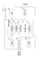
- FIG. 1 is a block diagram showing a configuration of a driver monitor 100 including an image detection device 30 according to the first embodiment.
- the driver monitor 100 is mounted on a vehicle and continuously photographs the interior of the vehicle in terms of time.
- the driver monitor 100 may record the captured image, or may discard it without recording it.
- the driver monitor 100 is arranged, for example, on the dashboard below the windshield of the vehicle.
- the video detection device 30 of the driver monitor 100 images, for example, a driver in a vehicle as an image-captured object, and recognizes the left and right eyes from the imaged face of the image-captured object.
- the image detection device 30 estimates the inclination angle of the left and right eyes with respect to the horizontal (hereinafter, the inclination angle with respect to the horizontal will be simply referred to as the inclination angle).
- the image detection device 30 rotationally corrects the inclinations of the left and right eyes based on the estimated inclination angles of the left and right eyes so that the left and right eyes are arranged substantially horizontally.
- the image detection device 30 calculates the rotation-corrected opening degrees of the left and right eyes, and determines the degree of drowsiness from the calculated opening degrees.
- the image detection device 30 calculates the frequency at which the tilt angles of the left and right eyes exceed a predetermined angle, and determines the degree of drowsiness from the calculated frequency.
- the image detection device 30 may rotate and correct the captured image itself based on the estimated tilt angles of the left and right eyes so that the left and right eyes are arranged substantially horizontally. Further, only the face detection frame in the captured image, or the image of the face detection frame and its peripheral portion may be rotationally corrected, and further, the rotational correction may be performed using other face parts other than the left and right eyes. Good. Further, the image detection device 30 may output information such as the estimated left and right eye inclination angles, the left and right eye opening degrees, and the frequency at which the left and right eye inclination angles exceed a predetermined angle to an external device, Further, it may be recorded as information accompanying the recorded image.
- the driver monitor 100 includes an imaging unit 10, a recording unit 20, a video detection device 30, an external input unit 40, an external output unit 41, and the like.
- the image capturing section 10 is a camera having a detector such as a CCD, and captures an image of, for example, a driver in a vehicle as an imaged object.
- the imaging unit 10 acquires images continuously in time and sends them to the image acquisition unit 31 of the image detection device 30 described later.
- the recording unit 20 is, for example, a removable medium such as an SD card or a USB memory, a hard disk, or the like, and is capable of recording and deleting the image acquired by the image acquisition unit 31.
- a removable medium such as an SD card or a USB memory, a hard disk, or the like
- the recording unit 20 may not be provided.
- the recording unit 20 can be detached from the driver monitor 100 and the image can be played back by another PC or the like.
- the external input unit 40 acquires vehicle speed information and position information from an external device.
- the external output unit 41 also outputs information such as the estimated left and right eye inclination angles, the left and right eye opening degrees, and the frequency at which the left and right eye inclination angles exceed a predetermined angle to an external device.
- the driver monitor 100 may add the speed information, the position information, and the like acquired by the external input unit 40 to the video and record the video.
- the video detection device 30 includes a video acquisition unit 31, a video recognition unit 32, a tilt angle estimation unit 33, a tilt correction unit 34, an opening calculation unit 35, and a drowsiness determination unit 36.
- the video detection device 30 is configured of, for example, a CPU and the like, and operates according to a computer program to execute the processing by the above-described units.
- the storage unit 30a includes a data storage device such as a RAM (Random Access Memory), a flash memory, and a hard disk storage device, and stores a computer program executed by the video detection device 30.
- the storage unit 30a also stores a recognition dictionary for recognizing the face, eyes, and the like of the subject to be captured from the captured image.
- the video acquisition unit 31 acquires the video captured by the imaging unit 10, performs processing such as data compression, and outputs the video to the recording unit 20.
- the image acquisition unit 31 may be configured to include the imaging unit 10.
- the video recognition unit 32 recognizes the face and left and right eyes of the imaged object from the video input from the video acquisition unit 31 based on the recognition dictionary stored in the storage unit 30a.
- the recognition dictionary stored in the storage unit 30a includes shape data such as faces and eyes, and the image recognition unit 32 extracts the shape pattern appearing in the image and includes it in the recognition dictionary.
- the left and right eyes are recognized by checking the shape data.
- the image recognition unit 32 can recognize the left and right eyes from the image by using a known image recognition processing method that has been developed in various fields.
- the inclination angle estimation unit 33 estimates the inclination angles of the left and right eyes moment by moment based on the positions of the left and right eyes recognized by the image recognition unit 32.
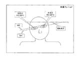
- FIG. 2 is a schematic diagram for explaining the inclination of the left and right eyes in a video frame.
- the tilt angle estimation unit 33 obtains the center points P1 and P2 of the left and right eyes, and estimates the angle formed by the straight line M1 connecting the center points P1 and P2 and the horizontal line L serving as the reference line in the video frame F as the tilt angle ⁇ . To do.
- the center points P1 and P2 of the left and right eyes are obtained as the center points of the pupils of the left and right eyes recognized by the image recognition unit 32.
- the straight line M1 indicates the direction in which the left and right eyes are lined up.
- a straight line M2 indicating a tangent to the contour of the eyes is obtained, and the angle formed by the straight line M2 and the horizontal line L is estimated as the inclination angle ⁇ .
- a straight line connecting the outer corners of the left and right eyes, a straight line connecting the inner corners of the eyes, and the like may be obtained, and the angle formed by these straight lines and the horizontal line L may be estimated as the inclination angle ⁇ .
- the tilt angle estimation unit 33 may independently estimate the tilt angles ⁇ of the left and right eyes for each continuous video frame. Further, the tilt angle estimation unit 33 performs rotation correction on the current video frame with the tilt angle ⁇ (n ⁇ 1) in the immediately preceding video frame, and then the left and right eyes are recognized by the video recognition unit 32, and then the tilt angle is calculated. The amount of change ⁇ (n) may be calculated to estimate the tilt angle ⁇ (n) in the current video frame. At this time, the inclination angle ⁇ (n) is expressed as follows.
- ⁇ (n) ⁇ (n-1) + ⁇ (n)
- the inclination angle estimating unit 33 may estimate the inclination angles of the left and right eyes by averaging the consecutive video frames.
- the left and right eyes move finely and the tilt angle slightly moves, by averaging the tilt angles of the left and right eyes between the video frames, it becomes easy to grasp a large movement of the left and right eyes.
- the tilt angle estimation unit 33 determines the position of the left and right eyes to be recognized first.
- the inclination angle estimated based on the inclination angle may be reset.
- the inclination angle estimation unit 33 prepares for a case in which at least one of the left and right eyes deviates from the angle of view of the imaging unit 10 and the left and right eyes can be detected within the angle of view immediately after deviating from the angle of view for a moment.
- the inclination angle estimated immediately before the angle of view deviates may be held.
- the tilt correction unit 34 adjusts the tilt of the left and right eyes based on the tilt angle ⁇ estimated by the tilt angle estimation unit 33 so that the left and right eyes are arranged parallel to the horizontal line L that is the reference line in the video frame F. Correct the rotation.
- FIG. 3 is a schematic diagram for explaining the left and right eyes whose rotation has been corrected.
- the tilt correction unit 34 integrally corrects the rotation of the left and right eyes so that the straight line M1 indicating the arrangement direction of the left and right eyes becomes a horizontal line that is a reference line in the video frame F.
- the opening degree calculation unit 35 calculates the opening degrees of the left and right eyes that are rotation-corrected by the inclination correction unit 34. As shown in FIG. 3, the opening degree calculation unit 35 determines a distance E1 between the intersections of the vertical line N1 passing through the center point P1 of the right eye and the upper edge portion and the lower edge portion of the right eye. Similarly, the opening degree calculation unit 35 obtains the distance E2 between the intersections of the vertical line N2 passing through the center point P2 of the left eye and the upper edge portion and the lower edge portion of the left eye.
- the opening degree calculation unit 35 may define the distances E1 and E2 themselves as opening degrees, measure the average distance En in the imaged object, and calculate the ratio (E1 / En) and the ratio (E2 / En). It may be defined as the opening degree. Further, the opening degree calculation unit 35 may measure the maximum distance Em in the imaged object and define the ratio (E1 / Em) and the ratio (E2 / Em) as the opening degree.
- the drowsiness determination unit 36 determines the degree of drowsiness occurring in the imaged object based on the movement of the left and right eyes recognized by the image recognition unit 32. The drowsiness determination unit 36 determines the degree of drowsiness based on the openings of the left and right eyes calculated by the opening calculation unit 35. The drowsiness determination unit 36 sets a predetermined threshold value for the opening degree of the left and right eyes, for example, and the degree of drowsiness is “small” when the opening degree is equal to or more than the threshold value, and the drowsiness degree is less than the threshold value. It is determined to be “large”.
- the drowsiness determination unit 36 may determine a degree of drowsiness in multiple stages by setting two or more threshold values for the opening degrees of the left and right eyes. Furthermore, the drowsiness determination unit 36 may determine the opening degrees of the left and right eyes themselves as the degree of drowsiness.
- the image acquired by the image acquisition unit 31 is subjected to image processing such as data compression as described above and recorded in the recording unit 20, but the inclination angles of the left and right eyes estimated momentarily by the inclination angle estimation unit 33. It may be recorded by the recording unit 20 after the rotation correction based on the above.
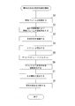
- FIG. 4 is a flowchart showing the procedure of the process of determining the degree of drowsiness in the video detection device 30.
- the driver monitor 100 acquires the video frame of the video imaged by the imaging unit 10 by the video acquisition unit 31 of the video detection device 30 (S1).
- the image recognition unit 32 rotationally corrects the image frame according to the previously estimated inclination angle ⁇ (n-1) (S2), and recognizes the left and right eyes as an image (S3). If the image recognition unit 32 is in the initial state in step S2, the previously estimated tilt angle ⁇ (n ⁇ 1) may be 0 deg.
- the tilt angle estimation unit 33 calculates the tilt angle change amount ⁇ (n) by obtaining the center points P1 and P2 of the left and right eyes recognized in step S3 (S4).
- the inclination angle estimation unit 33 estimates the inclination angles ⁇ (n) of the left and right eyes at the present time by adding the inclination angle change amount ⁇ (n) to the previously estimated inclination angle ⁇ (n ⁇ 1) (S5). ).
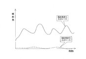
- FIG. 5 is a graph showing an example of the inclination angles of the left and right eyes estimated by the inclination angle estimation unit 33. In FIG. 5, the horizontal axis represents time t and the vertical axis represents the tilt angle ⁇ .
- the inclination correction unit 34 rotationally corrects the left and right eyes based on the inclination angles ⁇ (n) of the left and right eyes at the current time estimated in step S5 (S6).
- the opening calculator 35 calculates the rotation-corrected opening of the left and right eyes (S7).
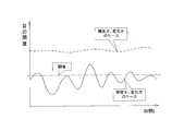
- FIG. 6 is a graph showing an example of the openings of the left and right eyes calculated by the opening calculation unit 35.
- the horizontal axis represents time t and the vertical axis represents the eye opening.
- the opening degree calculation unit 35 By estimating the opening degrees of the left and right eyes by the opening degree calculation unit 35 every moment, a case where the change in the opening degree is small, a case where the change in the opening degree is large, and the like appear.
- the eye opening is calculated for each of the left eye and the right eye, but may be handled independently for each of the left eye and the right eye, and averaging or either the maximum value or the minimum value may be adopted. Good.
- the drowsiness determination unit 36 determines the degree of drowsiness by comparing the eye opening calculated by the opening calculation unit 35 with a threshold value (S8), and ends the process. As shown in FIG. 6, the drowsiness determination unit 36 compares and determines, for example, one threshold value and the eye opening degree, and if the eye opening degree is equal to or more than the threshold value, the drowsiness degree is “small”. If it is less than the threshold value, it is determined that the degree of drowsiness is “large”.
- the image detection device 30 can obtain an image of a driver of a vehicle as an image-captured object, visually recognize the left and right eyes, and estimate the inclination angle of the left and right eyes moment by moment.
- the inclination correction unit 34 rotationally corrects the inclinations of the left and right eyes
- the opening degree calculation unit 35 calculates the opening degrees of the left and right eyes to easily and accurately calculate the eye opening degree. You can In addition, the image detection device 30 can correct the inclination based on the estimated inclination angles of the left and right eyes and determine the degree of drowsiness as the state of the imaged object.
- the inclination angle estimation unit 33 estimates the inclination angle by obtaining the variation ⁇ (n) of the inclination angle, that is, the difference between the video frames moment by moment.
- the image detection device 30 can easily recognize the images of the left and right eyes by recognizing the images of the left and right eyes in the image frame whose inclination is corrected by the inclination angle in the immediately previous image frame.
- the inclination angle estimation unit 33 estimates the inclination angle by averaging the video frames, so that even when the left and right eyes move finely and a slight movement of the inclination angle occurs, it is easy to grasp a large movement of the left and right eyes. ..
- the tilt angle estimation unit 33 resets the tilt angle estimated based on the right and left eyes first recognized next. , It is possible to recover from the discontinuity or instability that occurred in the estimation of the tilt angle.
- FIG. 7 is a block diagram showing the configuration of the driver monitor 100 including the video detection device 30 according to the second embodiment.
- the tilt frequency calculation unit 37 is provided, and the configuration and operation other than those specifically described below are the same as the configuration and operation described in the first embodiment, and thus the description is simplified. Therefore, the description is omitted.
- the inclination frequency calculation unit 37 counts the number of times the inclination angles of the left and right eyes exceed a predetermined angle during a fixed time, and calculates the frequency of inclination of the left and right eyes.
- the drowsiness determination unit 36 compares and determines the frequency of inclination of the left and right eyes calculated by the inclination frequency calculation unit 37 with a predetermined threshold value, and when the frequency is equal to or higher than the threshold value, the degree of drowsiness is “large”. If it is less than the threshold value, it is determined that the degree of drowsiness is “small”. Further, the drowsiness determination unit 36 may determine two or more thresholds for the frequency of inclination of the left and right eyes and determine the degree of drowsiness in multiple stages. Furthermore, the drowsiness determination unit 36 may determine the frequency of inclination of the left and right eyes itself as the degree of drowsiness.
- the inclination frequency calculation unit 37 may calculate the duty obtained by measuring the time when the inclination angle of the left and right eyes exceeds a predetermined angle for a certain period of time as the frequency of inclination of the left and right eyes.
- the comparison determination of the frequency of inclination of the left and right eyes and the predetermined threshold by the drowsiness determination unit 36 is the same as described above.
- the drowsiness determination unit 36 determines, based on the duty calculated by the tilt frequency calculation unit 37, that the degree of drowsiness is “large” when the tilt angle of the left and right eyes exceeds the predetermined angle for a long time, and the time over the predetermined angle is exceeded. When is short, it is determined that the degree of drowsiness is “small”.
- the degree of drowsiness is determined as the state of the image-captured object.
- the degree of physical fatigue may be determined.
- the video detection device 30 includes a video acquisition unit 31, a video recognition unit 32, and a tilt angle estimation unit 33.
- the image acquisition unit 31 acquires an image of the face of the object to be imaged.
- the image recognition unit 32 recognizes the left and right eyes from the image acquired by the image acquisition unit 31.
- the tilt angle estimation unit 33 estimates the tilt angle with respect to the horizontal based on the positions of the left and right eyes recognized by the image recognition unit 32. Thereby, the image detection device 30 can estimate the inclination of the left and right eyes from moment to moment from the image of the face of the object to be imaged.
- the tilt angle estimation unit 33 estimates the tilt angles of the left and right eyes by obtaining the difference between the video frames. As a result, the video detection device 30 recognizes the left and right eyes while correcting the tilt of the video frame, so that the left and right eyes can be easily recognized.
- the tilt angle estimation unit 33 estimates the tilt angles of the left and right eyes by averaging the video frames. As a result, the image detection device 30 can easily recognize a large movement of the left and right eyes even when the left and right eyes move finely and a slight movement of the tilt angle occurs.
- the tilt angle estimation unit 33 estimates the tilt angle based on the tilt angle estimated based on the right and left eyes first recognized next. Reset the tilt angle. As a result, the image detection device 30 can recover from the discontinuity or the unstable state that has occurred in the estimation of the tilt angle.
- the video detection device 30 also includes a tilt correction unit 34 and an opening degree calculation unit 35.
- the tilt correction unit 34 corrects the tilt of the left and right eyes based on the tilt angle estimated by the tilt angle estimation unit 33.
- the opening degree calculation unit 35 calculates the opening degrees of the left and right eyes corrected by the inclination correction unit 34. Accordingly, the image detection device 30 can easily and accurately calculate the eye opening degree after rotationally correcting the inclination of the left and right eyes.
- the image detection device 30 also includes a tilt frequency calculation unit 37 that calculates the frequency at which the tilt angle estimated by the tilt angle estimation unit 33 exceeds a predetermined angle. With this, the image detection device 30 can obtain and output the tilt frequency of the left and right eyes from the acquired video, and can use the tilt frequency, for example, to determine the degree of drowsiness of the imaged object.
- the video detection device 30 also includes a drowsiness determination unit 36 that determines the degree of drowsiness of the imaged object based on the left and right eyes recognized by the video recognition unit 32. Thereby, the image detection device 30 can determine the degree of drowsiness as the state of the imaged object.
- the video detection method includes a video acquisition step, a video recognition step, and a tilt angle estimation step.
- the image acquisition step acquires an image of the face of the object to be imaged.
- the image recognition step recognizes the left and right eyes from the image acquired by the image acquisition step.
- the inclination angle estimating step estimates the inclination angle with respect to the horizontal based on the positions of the left and right eyes recognized by the image recognizing step. According to this image detection method, the inclinations of the left and right eyes can be estimated every moment from the image of the face of the object to be imaged.
- the video detection program causes a computer to execute a video acquisition step, a video recognition step, and a tilt angle estimation step.
- the image acquisition step acquires an image of the face of the object to be imaged.
- the image recognition step recognizes the left and right eyes from the image acquired by the image acquisition step.
- the inclination angle estimating step estimates the inclination angle with respect to the horizontal based on the positions of the left and right eyes recognized by the image recognizing step. According to this image detection program, it is possible to estimate the inclination of the left and right eyes from moment to moment from the image of the face of the object to be imaged.
- the present invention relates to a video detection device, a video detection method, and a video detection program.
Landscapes
- Engineering & Computer Science (AREA)
- Physics & Mathematics (AREA)
- General Physics & Mathematics (AREA)
- Theoretical Computer Science (AREA)
- Multimedia (AREA)
- Health & Medical Sciences (AREA)
- General Health & Medical Sciences (AREA)
- Human Computer Interaction (AREA)
- Computer Vision & Pattern Recognition (AREA)
- Oral & Maxillofacial Surgery (AREA)
- Ophthalmology & Optometry (AREA)
- Psychiatry (AREA)
- Social Psychology (AREA)
- Image Analysis (AREA)
- Traffic Control Systems (AREA)
- Image Processing (AREA)
- Fittings On The Vehicle Exterior For Carrying Loads, And Devices For Holding Or Mounting Articles (AREA)
Abstract
映像検出装置(30)は、映像取得部(31)、映像認識部(32)および傾斜角推定部(33)を備える。映像取得部(31)は被撮像体の顔を撮影した映像を取得する。映像認識部(32)は、映像取得部(31)によって取得された映像から左右の目を認識する。傾斜角推定部(33)は、映像認識部(32)により認識された左右の目の位置に基づいて水平に対する傾斜角を推定する。
Description
本発明は、映像検出装置、映像検出方法および映像検出プログラムに関する。
例えば車両に搭載されるドライブレコーダ等では、車両の外部や車室内を撮像して得られる映像を記憶装置に記憶する。車室内を撮像する場合、車室内の様子を映像として記憶することや、運転者を中心に映像を記憶することなどが行われる。
例えば、特許文献1には、撮影される人物の顔に相当する顔領域を含む原画像の画像データに基づいて、原画像中の人物の両目に相当する位置をそれぞれ検出する画像処理方法が開示されている。この画像処理方法は、検出された原画像中の人物の両目に相当する位置が、原画像に対して予め設定されている基準線またはこの基準線に直交する直線に平行な同一直線上に位置するように、原画像を修正して、修正画像データを作成する。この画像処理方法は、原画像中の人物の顔に相当する顔領域の傾きを自動的に修正し、例えば証明写真の作成などに用いられる。
特許文献1に記載の従来の画像処理方法は、証明写真のような静止画像に対して左右の目の位置を検出して画像を修正することを考慮しているが、動画像として取得される映像に対して適用することについては考慮されていなかった。また、従来の画像処理方法では、映像から認識される左右の目の開度や傾き等の目の動きに基づいて、被撮像体の状態を推定することは検討されていなかった。
本発明は、斯かる事情に鑑みてなされたものであり、その目的とするところは、被撮像体の顔を撮像した映像から時々刻々における左右の目の傾きを推定し、更には被撮像体の状態を推定することができる映像検出装置、映像検出方法および映像検出プログラムを提供することにある。
本実施形態のある態様の映像検出装置は、被撮像体の顔を撮影した映像を取得する映像取得部と、前記映像取得部によって取得された映像から左右の目を認識する映像認識部と、前記映像認識部により認識された左右の目の位置に基づいて水平に対する傾斜角を推定する傾斜角推定部と、を備える。
また本実施形態の別の態様は映像検出方法である。この映像検出方法は、被撮像体の顔を撮影した映像を取得する映像取得ステップと、前記映像取得ステップによって取得された映像から左右の目を認識する映像認識ステップと、前記映像認識ステップにより認識された左右の目の位置に基づいて水平に対する傾斜角を推定する傾斜角推定ステップと、を備える。
本実施形態によれば、被撮像体の顔を撮像した映像から時々刻々における左右の目の傾きを推定することができる。
以下、本発明を好適な実施の形態をもとに図1から図7を参照しながら説明する。各図面に示される同一または同等の構成要素、部材には、同一の符号を付するものとし、適宜重複した説明は省略する。また、各図面における部材の寸法は、理解を容易にするために適宜拡大、縮小して示される。また、各図面において実施の形態を説明する上で重要ではない部材の一部は省略して表示する。
(実施形態1)
図1は、実施形態1に係る映像検出装置30を含むドライバーモニター100の構成を示すブロック図である。ドライバーモニター100は、車両に搭載され、車両の車室内を時間的に連続して撮影する。ドライバーモニター100は撮影した映像を記録するようにしてもよいし、記録せずに破棄してもよい。ドライバーモニター100は、例えば車両のフロントガラスの下方におけるダッシュボード上などに配置される。ドライバーモニター100の映像検出装置30は、被撮像体として、例えば車両に搭乗している運転者を被撮像体として撮像し、撮像された被撮像体の顔から左右の目を認識する。映像検出装置30は、左右の目の水平に対する傾斜角(以下、水平に対する傾斜角を単に傾斜角と呼ぶ。)を時々刻々推定する。
図1は、実施形態1に係る映像検出装置30を含むドライバーモニター100の構成を示すブロック図である。ドライバーモニター100は、車両に搭載され、車両の車室内を時間的に連続して撮影する。ドライバーモニター100は撮影した映像を記録するようにしてもよいし、記録せずに破棄してもよい。ドライバーモニター100は、例えば車両のフロントガラスの下方におけるダッシュボード上などに配置される。ドライバーモニター100の映像検出装置30は、被撮像体として、例えば車両に搭乗している運転者を被撮像体として撮像し、撮像された被撮像体の顔から左右の目を認識する。映像検出装置30は、左右の目の水平に対する傾斜角(以下、水平に対する傾斜角を単に傾斜角と呼ぶ。)を時々刻々推定する。
映像検出装置30は、推定した左右の目の傾斜角に基づいて、左右の目が概ね水平に配置されるように左右の目の傾きを回転補正する。映像検出装置30は、回転補正した左右の目の開度を算出し、算出した開度から眠気の度合を判定する。また、映像検出装置30は、左右の目の傾斜角が所定角を超える頻度を算出し、算出した頻度から眠気の度合を判定する。
映像検出装置30は、推定した左右の目の傾斜角に基づいて、撮像された映像自体を左右の目が概ね水平に配置されるように回転補正してもよい。また、撮像された映像のうち顔検出枠のみ、或いは顔検出枠とその周辺部分の画像を回転補正してもよく、更には左右の目以外の他の顔の部位を用いて回転補正してもよい。また、映像検出装置30は、推定した左右の目の傾斜角、左右の目の開度、および左右の目の傾斜角が所定角を超える頻度等の情報を外部装置へ出力してもよく、更には記録する映像に付随する情報として記録してもよい。
ドライバーモニター100は、撮像部10、記録部20、映像検出装置30、外部入力部40および外部出力部41等を備える。撮像部10は、例えばCCD等の検出器を有するカメラであり、車両に搭乗している例えば運転者を被撮像体として撮像する。撮像部10は、時間的に連続して映像を取得し、後述する映像検出装置30の映像取得部31へ送出する。
記録部20は、例えばSDカードやUSBメモリ等の着脱可能な媒体や、ハードディスクなどであり、映像取得部31で取得された映像を記録し、削除することができるものとする。以下、記録部20が設けられた構成について説明するが、ドライバーモニター100が映像を記録する部分を持たない場合には記録部20は設けなくてもよい。記録部20は、ドライバーモニター100に着脱可能とすることで、ドライバーモニター100から取り外し、別のPC等で映像を再生等することができる。
外部入力部40は、車両の速度情報および位置情報等を外部装置から取得する。また外部出力部41は、推定した左右の目の傾斜角、左右の目の開度、および左右の目の傾斜角が所定角を超える頻度等の情報を外部装置へ出力する。ドライバーモニター100は、外部入力部40によって取得した速度情報および位置情報等を映像に付加して記録するようにしてもよい。
映像検出装置30は、映像取得部31、映像認識部32、傾斜角推定部33、傾き補正部34、開度算出部35および眠気判定部36を有する。映像検出装置30は、例えばCPUなどによって構成され、コンピュータプログラムに従って動作することによって、上述の各部による処理を実行する。記憶部30aは、RAM(Random Access Memory)、フラッシュメモリ、ハードディスク記憶装置等のデータ記憶装置によって構成されており、映像検出装置30で実行するコンピュータプログラム等を記憶する。また記憶部30aは、撮像された映像から被撮像体の顔や目等を認識するための認識用辞書を記憶している。
映像取得部31は、撮像部10において撮影された映像を取得してデータ圧縮等の処理を行い、記録部20に出力する。尚、映像取得部31は、撮像部10を含んで構成されていてもよい。
映像認識部32は、記憶部30aに記憶された認識用辞書に基づいて、映像取得部31から入力された映像から被撮像体の顔や左右の目を認識する。記憶部30aに記憶した認識用辞書には、顔や目等の形状データ等が含まれており、映像認識部32は、映像に表われている形状パターンを抽出し、認識用辞書に含まれる形状データと照合することによって左右の目を認識する。映像認識部32は、様々な分野において開発されてきた公知の画像認識処理の手法を用いて、映像から左右の目を認識することができる。
傾斜角推定部33は、映像認識部32によって認識された左右の目の位置に基づいて、左右の目の傾斜角を時々刻々と推定する。図2は、映像フレームにおける左右の目の傾斜について説明するための模式図である。傾斜角推定部33は、左右の目の中心点P1およびP2を求め、中心点P1およびP2を結ぶ直線M1と、映像フレームFにおける基準線となる水平線Lとがなす角度を傾斜角θとして推定する。左右の目の中心点P1およびP2は、映像認識部32によって認識された左右の目における瞳の中心点として求められる。
直線M1は左右の目が並ぶ方向を示しているが、例えば図2に示すように目の輪郭における接線を示す直線M2を求め、直線M2と水平線Lとがなす角度を傾斜角θとして推定してもよい。このほか、左右の目の目尻同士を結ぶ直線や、目頭同士を結ぶ直線などを求め、これらの直線と水平線Lとがなす角度を傾斜角θとして推定してもよい。
傾斜角推定部33は、左右の目の傾斜角θを連続する映像フレームごとに独立的に推定してもよい。また傾斜角推定部33は、1つ前の映像フレームにおける傾斜角θ(n-1)で、現時点の映像フレームを回転補正した後、映像認識部32によって左右の目を認識した後、傾斜角の変化量Δθ(n)を算出し、現在の映像フレームにおける傾斜角θ(n)を推定してもよい。このとき、傾斜角θ(n)は次のように表される。
θ(n)=θ(n-1)+Δθ(n)
現時点の映像フレームをθ(n-1)で一旦回転補正することにより、左右の目の傾きが小さくなって映像認識が容易になり、変化量Δθ(n)をより正確に求めることができる。
θ(n)=θ(n-1)+Δθ(n)
現時点の映像フレームをθ(n-1)で一旦回転補正することにより、左右の目の傾きが小さくなって映像認識が容易になり、変化量Δθ(n)をより正確に求めることができる。
また、傾斜角推定部33は、連続する映像フレーム間で平均化して左右の目の傾斜角を推定するようにしてもよい。左右の目が細かく動いて傾斜角の微動が生じる場合、映像フレーム間で左右の目の傾斜角を平均化することで、左右の目の大きな動きが把握し易くなる。
また、傾斜角推定部33は、左右の目の少なくとも一方が所定期間に亘って映像認識されず傾斜角を推定することができない場合には、次に最初に認識される左右の目の位置に基づいて推定される傾斜角で推定している傾斜角をリセットするようにしてもよい。また、傾斜角推定部33は、左右の目の少なくとも一方が撮像部10の画角から外れた場合、一瞬画角から外れてすぐに画角内で左右の目が検出され得る場合に備えて、画角から外れる直前に推定された傾斜角を保持するようにしてもよい。
傾き補正部34は、傾斜角推定部33によって推定した傾斜角θに基づいて、左右の目が映像フレームFにおける基準線である水平線Lと平行に配置されるように、左右の目の傾きを回転補正する。図3は、回転補正された左右の目について説明するための模式図である。傾き補正部34は、左右の目の並び方向を示す直線M1が映像フレームFにおける基準線である水平線となるように、左右の目を一体的に回転補正する。
開度算出部35は、傾き補正部34によって回転補正された左右の目の開度を算出する。図3に示すように、開度算出部35は、右目の中心点P1を通る鉛直線N1と、右目の上縁部および下縁部との交点間の距離E1を求める。同様に、開度算出部35は、左目の中心点P2を通る鉛直線N2と、左目の上縁部および下縁部との交点間の距離E2を求める。開度算出部35は、距離E1およびE2自体を開度として定義してもよいし、被撮像体において平均的な距離Enを測定し、比率(E1/En)および比率(E2/En)を開度として定義してもよい。また、開度算出部35は、被撮像体において最大の距離Emを測定し、比率(E1/Em)および比率(E2/Em)を開度として定義するなどしてもよい。
眠気判定部36は、映像認識部32によって認識された左右の目の動きに基づいて被撮像体に生じている眠気の度合を判定する。眠気判定部36は、開度算出部35によって算出された左右の目の開度に基づいて眠気の度合を判定する。眠気判定部36は、例えば左右の目の開度について所定の閾値を定め、開度が該閾値以上である場合に眠気の度合が「小」と、該閾値未満である場合に眠気の度合が「大」であると判定する。また、眠気判定部36は、左右の目の開度について2以上の複数の閾値を定め、多段階で眠気の度合を判定するようにしてもよい。さらに、眠気判定部36は、左右の目の開度そのものを眠気の度合として判定するものであってもよい。
映像取得部31によって取得された映像は、上述のようにデータ圧縮等の映像処理を行って記録部20で記録されるが、傾斜角推定部33によって時々刻々推定される左右の目の傾斜角に基づいて回転補正した後、記録部20で記録されてもよい。
次に映像検出装置30の動作について、眠気の度合の判定処理に基づいて説明する。図4は、映像検出装置30における眠気の度合の判定処理の手順を示すフローチャートである。ドライバーモニター100は、撮像部10によって撮影した映像の映像フレームを映像検出装置30の映像取得部31で取得している(S1)。
映像認識部32は、前回推定された傾斜角θ(n-1)によって映像フレームを回転補正し(S2)、左右の目を映像認識する(S3)。映像認識部32は、ステップS2において初期状態である場合には、前回推定された傾斜角θ(n-1)を0degであるとすればよい。
傾斜角推定部33は、ステップS3によって認識された左右の目の中心点P1およびP2を求めて傾斜角の変化量Δθ(n)を算出する(S4)。傾斜角推定部33は、現時点における左右の目の傾斜角θ(n)を前回推定された傾斜角θ(n-1)に傾斜角の変化量Δθ(n)を加算して推定する(S5)。図5は、傾斜角推定部33により推定された左右の目の傾斜角の例を示すグラフである。図5において横軸は時間tを縦軸は傾斜角θを表している。傾斜角推定部33によって時々刻々左右の目の傾斜角を推定することにより、傾斜角の変化が小さいケースや、傾斜角の変化が大きいケースなどが現れる。
傾き補正部34は、ステップS5において推定された現時点における左右の目の傾斜角θ(n)によって左右の目を回転補正する(S6)。傾き補正部34での回転補正によって、例えば図3に示すように左右の目が並ぶ方向が概ね水平となる。開度算出部35は、回転補正された左右の目の開度を算出する(S7)。図6は、開度算出部35により算出された左右の目の開度の例を示すグラフである。図6において横軸は時間tを縦軸は目の開度を表している。開度算出部35によって時々刻々左右の目の開度を推定することにより、開度の変化が小さいケースや、開度の変化が大きいケースなどが現れる。尚、目の開度は、左目および右目ごとに算出されるが、左目および右目ごとに独立的に扱ってもよいし、平均化や、最大値または最小値のいずれかを採用するようにしてもよい。
眠気判定部36は、開度算出部35により算出された目の開度を閾値と比較判定することにより眠気の度合を判定し(S8)、処理を終了する。図6に示すように、眠気判定部36は、例えば1つの閾値と目の開度とを比較判定し、目の開度が閾値以上である場合には眠気の度合が「小」であると、閾値未満である場合には眠気の度合が「大」であると判定する。
映像検出装置30は、被撮像体としての車両の運転者を撮像した映像を取得し、左右の目を映像認識し、左右の目の傾斜角を時々刻々推定することができる。映像検出装置30は、左右の目の傾きを傾き補正部34により回転補正し、開度算出部35により左右の目の開度を算出することで簡単で正確に目の開度を算出することができる。また、映像検出装置30は、推定した左右の目の傾斜角に基づいて傾きを補正し、被撮像体の状態として眠気の度合を判定することができる。
また上述のように、傾斜角推定部33において、傾斜角の変化分Δθ(n)、即ち映像フレーム間における差分を時々刻々と求めて傾斜角を推定する。映像検出装置30は、1つ前の映像フレームにおける傾斜角によって傾きが補正された映像フレームにおいて左右の目を映像認識することで、左右の目の映像認識が容易に行える。
また傾斜角推定部33において映像フレーム間で平均化して傾斜角を推定することで、左右の目が細かく動いて傾斜角の微動が生じる場合にも、左右の目の大きな動きが把握し易くなる。
また傾斜角推定部33は、映像認識部32により左右の目の少なくとも一方が一定期間認識されない場合には、次に最初に認識される左右の目に基づいて推定される傾斜角によってリセットして、傾斜角の推定において生じた不連続や不安定状態からリカバリーすることができる。
(実施形態2)
実施形態1では左右の目の開度に基づいて被撮像体の状態としての眠気の度合を判定したが、左右の目の傾斜角が所定角度を超える頻度を算出することによって眠気の度合を判定するようにしてもよい。図7は、実施形態2に係る映像検出装置30を含むドライバーモニター100の構成を示すブロック図である。実施形態2に係る映像検出装置30では、傾斜頻度算出部37を設けており、以下に特に説明する以外の構成および動作は実施形態1において説明した構成および動作と同様であり、記載の簡潔のため説明を省略する。
実施形態1では左右の目の開度に基づいて被撮像体の状態としての眠気の度合を判定したが、左右の目の傾斜角が所定角度を超える頻度を算出することによって眠気の度合を判定するようにしてもよい。図7は、実施形態2に係る映像検出装置30を含むドライバーモニター100の構成を示すブロック図である。実施形態2に係る映像検出装置30では、傾斜頻度算出部37を設けており、以下に特に説明する以外の構成および動作は実施形態1において説明した構成および動作と同様であり、記載の簡潔のため説明を省略する。
傾斜頻度算出部37は、一定時間の間に左右の目の傾斜角が所定角度を超える回数をカウントして、左右の目の傾斜の頻度を算出する。眠気判定部36は、傾斜頻度算出部37により算出された左右の目の傾斜の頻度と所定の閾値とを比較判定し、頻度が該閾値以上である場合に眠気の度合が「大」であり、該閾値未満である場合に眠気の度合が「小」であると判定する。また、眠気判定部36は、左右の目の傾斜の頻度について2以上の複数の閾値を定め、多段階で眠気の度合を判定するようにしてもよい。さらに、眠気判定部36は、左右の目の傾斜の頻度そのものを眠気の度合として判定するものであってもよい。
また、傾斜頻度算出部37は、一定時間の間に左右の目の傾斜角が所定角度を超える時間を計測して得られるデューティを左右の目の傾斜の頻度として算出してもよい。眠気判定部36による左右の目の傾斜の頻度と所定の閾値との比較判定は、上述と同様である。眠気判定部36は、傾斜頻度算出部37によって算出されるデューティに基づき、左右の目の傾斜角が所定角度を超える時間が長い場合に眠気の度合が「大」であり、所定角度を超える時間が短い場合に眠気の度合が「小」であると判定する。
実施形態1および2において、被撮像体の状態として眠気の度合を判定する例を示したが、左右の目に表われる被撮像体の状態として、気持ちの不安や感情的な喜怒の度合、身体的な疲れの度合などを判定するようにしてもよい。
次に、上述の各実施形態に係る映像検出装置30、映像検出方法および映像検出プログラムの特徴を説明する。
実施形態に係る映像検出装置30は、映像取得部31、映像認識部32および傾斜角推定部33を備える。映像取得部31は被撮像体の顔を撮影した映像を取得する。映像認識部32は、映像取得部31によって取得された映像から左右の目を認識する。傾斜角推定部33は、映像認識部32により認識された左右の目の位置に基づいて水平に対する傾斜角を推定する。これにより、映像検出装置30は、被撮像体の顔を撮像した映像から時々刻々における左右の目の傾きを推定することができる。
実施形態に係る映像検出装置30は、映像取得部31、映像認識部32および傾斜角推定部33を備える。映像取得部31は被撮像体の顔を撮影した映像を取得する。映像認識部32は、映像取得部31によって取得された映像から左右の目を認識する。傾斜角推定部33は、映像認識部32により認識された左右の目の位置に基づいて水平に対する傾斜角を推定する。これにより、映像検出装置30は、被撮像体の顔を撮像した映像から時々刻々における左右の目の傾きを推定することができる。
また、傾斜角推定部33は、映像フレーム間における差分を求めて左右の目の傾斜角を推定する。これにより、映像検出装置30は、映像フレームの傾きを補正しつつ左右の目を映像認識するので、左右の目の映像認識が容易に行える。
また、傾斜角推定部33は、映像フレーム間で平均化して左右の目の傾斜角を推定する。これにより、映像検出装置30は、左右の目が細かく動いて傾斜角の微動が生じる場合にも、左右の目の大きな動きが把握し易くなる。
また、傾斜角推定部33は、映像認識部32により左右の目の少なくとも一方が一定期間認識されない場合、次に最初に認識される左右の目に基づいて推定される傾斜角によって推定している傾斜角をリセットする。これにより、映像検出装置30は、傾斜角の推定において生じた不連続や不安定状態からリカバリーすることができる。
また、映像検出装置30は、傾き補正部34および開度算出部35を備える。傾き補正部34は、傾斜角推定部33により推定した傾斜角に基づいて左右の目の傾きを補正する。開度算出部35は、傾き補正部34により補正された左右の目の開度を算出する。これにより、映像検出装置30は、左右の目の傾斜を回転補正した上で簡単で正確に目の開度を算出することができる。
また、映像検出装置30は、傾斜角推定部33により推定した傾斜角が所定角度を超える頻度を算出する傾斜頻度算出部37を備える。これにより、映像検出装置30は、取得した映像から左右の目の傾斜頻度を求めて出力することができ、例えば、傾斜頻度を被撮像体の眠気の度合の判定などに利用することができる。
また、映像検出装置30は、映像認識部32により認識された左右の目に基づいて、被撮像体の眠気の度合を判定する眠気判定部36を備える。これにより、映像検出装置30は、被撮像体の状態として眠気の度合を判定することができる。
実施形態に係る映像検出方法は、映像取得ステップ、映像認識ステップおよび傾斜角推定ステップを備える。映像取得ステップは、被撮像体の顔を撮影した映像を取得する。映像認識ステップは、映像取得ステップによって取得された映像から左右の目を認識する。傾斜角推定ステップは、映像認識ステップにより認識された左右の目の位置に基づいて水平に対する傾斜角を推定する。この映像検出方法によれば、被撮像体の顔を撮像した映像から時々刻々における左右の目の傾きを推定することができる。
実施形態に係る映像検出プログラムは、映像取得ステップ、映像認識ステップおよび傾斜角推定ステップをコンピュータに実行させる。映像取得ステップは、被撮像体の顔を撮影した映像を取得する。映像認識ステップは、映像取得ステップによって取得された映像から左右の目を認識する。傾斜角推定ステップは、映像認識ステップにより認識された左右の目の位置に基づいて水平に対する傾斜角を推定する。この映像検出プログラムによれば、被撮像体の顔を撮像した映像から時々刻々における左右の目の傾きを推定することができる。
以上、本発明の実施の形態をもとに説明した。これらの実施の形態は例示であり、いろいろな変形および変更が本発明の特許請求範囲内で可能なこと、またそうした変形例および変更も本発明の特許請求の範囲にあることは当業者に理解されるところである。従って、本明細書での記述および図面は限定的ではなく例証的に扱われるべきものである。
本発明は、映像検出装置、映像検出方法および映像検出プログラムに関する。
30 映像検出装置、 31 映像取得部、 32 映像認識部、
33 傾斜角推定部、 34 傾き補正部、 35 開度算出部、
36 眠気判定部、 37 傾斜頻度算出部。
33 傾斜角推定部、 34 傾き補正部、 35 開度算出部、
36 眠気判定部、 37 傾斜頻度算出部。
Claims (9)
- 被撮像体の顔を撮影した映像を取得する映像取得部と、
前記映像取得部によって取得された映像から左右の目を認識する映像認識部と、
前記映像認識部により認識された左右の目の位置に基づいて水平に対する傾斜角を推定する傾斜角推定部と、
を備えることを特徴とする映像検出装置。 - 前記傾斜角推定部は、映像フレーム間における差分を求めて傾斜角を推定することを特徴とする請求項1に記載の映像検出装置。
- 前記傾斜角推定部は、映像フレーム間で平均化して傾斜角を推定することを特徴とする請求項1または2に記載の映像検出装置。
- 前記傾斜角推定部は、前記映像認識部により左右の目の少なくとも一方が一定期間認識されない場合、次に最初に認識される左右の目に基づいて推定される傾斜角によって推定している傾斜角をリセットすることを特徴とする請求項2または3に記載の映像検出装置。
- 前記傾斜角推定部により推定した傾斜角に基づいて左右の目の傾きを補正する傾き補正部と、
前記傾き補正部により補正された左右の目の開度を算出する開度算出部と、
を備えることを特徴とする請求項1から4のいずれか1項に記載の映像検出装置。 - 前記傾斜角推定部により推定した傾斜角が所定角度を超える頻度を算出する傾斜頻度算出部と、
を備えることを特徴とする請求項1から4のいずれか1項に記載の映像検出装置。 - 前記映像認識部により認識された左右の目に基づいて、被撮像体の眠気の度合を判定する眠気判定部と、
を備えることを特徴とする請求項1から6のいずれか1項に記載の映像検出装置。 - 被撮像体の顔を撮影した映像を取得する映像取得ステップと、
前記映像取得ステップによって取得された映像から左右の目を認識する映像認識ステップと、
前記映像認識ステップにより認識された左右の目の位置に基づいて水平に対する傾斜角を推定する傾斜角推定ステップと、
を備えることを特徴とする映像検出方法。 - 被撮像体の顔を撮影した映像を取得する映像取得ステップと、
前記映像取得ステップによって取得された映像から左右の目を認識する映像認識ステップと、
前記映像認識ステップにより認識された左右の目の位置に基づいて水平に対する傾斜角を推定する傾斜角推定ステップと、
をコンピュータに実行させることを特徴とする映像検出プログラム。
Priority Applications (1)
| Application Number | Priority Date | Filing Date | Title |
|---|---|---|---|
| US17/314,323 US11551446B2 (en) | 2018-11-09 | 2021-05-07 | Video detection device, and video detection method |
Applications Claiming Priority (2)
| Application Number | Priority Date | Filing Date | Title |
|---|---|---|---|
| JP2018-211631 | 2018-11-09 | ||
| JP2018211631A JP7107178B2 (ja) | 2018-11-09 | 2018-11-09 | 映像検出装置、映像検出方法および映像検出プログラム |
Related Child Applications (1)
| Application Number | Title | Priority Date | Filing Date |
|---|---|---|---|
| US17/314,323 Continuation US11551446B2 (en) | 2018-11-09 | 2021-05-07 | Video detection device, and video detection method |
Publications (1)
| Publication Number | Publication Date |
|---|---|
| WO2020095529A1 true WO2020095529A1 (ja) | 2020-05-14 |
Family
ID=70610861
Family Applications (1)
| Application Number | Title | Priority Date | Filing Date |
|---|---|---|---|
| PCT/JP2019/035304 Ceased WO2020095529A1 (ja) | 2018-11-09 | 2019-09-09 | 映像検出装置、映像検出方法および映像検出プログラム |
Country Status (3)
| Country | Link |
|---|---|
| US (1) | US11551446B2 (ja) |
| JP (1) | JP7107178B2 (ja) |
| WO (1) | WO2020095529A1 (ja) |
Citations (3)
| Publication number | Priority date | Publication date | Assignee | Title |
|---|---|---|---|---|
| JPH07296299A (ja) * | 1994-04-20 | 1995-11-10 | Nissan Motor Co Ltd | 画像処理装置およびそれを用いた居眠り警報装置 |
| JPH0935070A (ja) * | 1995-07-14 | 1997-02-07 | Mitsubishi Electric Corp | 顔画像処理装置 |
| JP2005339288A (ja) * | 2004-05-27 | 2005-12-08 | Toshiba Corp | 画像処理装置及びその方法 |
Family Cites Families (4)
| Publication number | Priority date | Publication date | Assignee | Title |
|---|---|---|---|---|
| JP3913604B2 (ja) | 2002-04-26 | 2007-05-09 | 富士フイルム株式会社 | 証明写真の作成方法 |
| JP4552636B2 (ja) * | 2004-12-08 | 2010-09-29 | 日産自動車株式会社 | ドライバモニタシステムおよびその処理方法 |
| US9460601B2 (en) * | 2009-09-20 | 2016-10-04 | Tibet MIMAR | Driver distraction and drowsiness warning and sleepiness reduction for accident avoidance |
| CN104182046A (zh) * | 2014-08-22 | 2014-12-03 | 京东方科技集团股份有限公司 | 眼控提醒方法、眼控图像显示方法及显示系统 |
-
2018
- 2018-11-09 JP JP2018211631A patent/JP7107178B2/ja active Active
-
2019
- 2019-09-09 WO PCT/JP2019/035304 patent/WO2020095529A1/ja not_active Ceased
-
2021
- 2021-05-07 US US17/314,323 patent/US11551446B2/en active Active
Patent Citations (3)
| Publication number | Priority date | Publication date | Assignee | Title |
|---|---|---|---|---|
| JPH07296299A (ja) * | 1994-04-20 | 1995-11-10 | Nissan Motor Co Ltd | 画像処理装置およびそれを用いた居眠り警報装置 |
| JPH0935070A (ja) * | 1995-07-14 | 1997-02-07 | Mitsubishi Electric Corp | 顔画像処理装置 |
| JP2005339288A (ja) * | 2004-05-27 | 2005-12-08 | Toshiba Corp | 画像処理装置及びその方法 |
Also Published As
| Publication number | Publication date |
|---|---|
| US11551446B2 (en) | 2023-01-10 |
| JP7107178B2 (ja) | 2022-07-27 |
| JP2020077338A (ja) | 2020-05-21 |
| US20210264156A1 (en) | 2021-08-26 |
Similar Documents
| Publication | Publication Date | Title |
|---|---|---|
| US8648918B2 (en) | Method and system for obtaining a point spread function using motion information | |
| JP3600755B2 (ja) | 顔画像処理装置 | |
| US7925048B2 (en) | Feature point detecting device, feature point detecting method, and feature point detecting program | |
| US9799118B2 (en) | Image processing apparatus, imaging apparatus and distance correction method | |
| US8649593B2 (en) | Image processing apparatus, image processing method, and program | |
| US9330325B2 (en) | Apparatus and method for reducing noise in fingerprint images | |
| CN111340749B (zh) | 图像质量的检测方法、装置、设备及存储介质 | |
| CN110378181A (zh) | 图像解析装置、图像解析方法及记录介质 | |
| CN110378182B (zh) | 图像解析装置、图像解析方法及记录介质 | |
| TW201328319A (zh) | 在立體影像中用以消除雜訊的裝置及方法 | |
| JP6885474B2 (ja) | 画像処理装置、画像処理方法、及び、プログラム | |
| CN102548465A (zh) | 视线估计装置 | |
| US12033429B2 (en) | Image processing device of determining authenticity of object, image processing method of determining authenticity of object, and storage medium storing program of determining authenticity of object | |
| JP2013251005A (ja) | 画像補正方法 | |
| JP6799325B2 (ja) | 画像補正装置、画像補正方法、注目点認識装置、注目点認識方法及び異常検知システム | |
| JP7784095B2 (ja) | 車両段差測定方法、装置、およびコンピュータプログラム | |
| WO2020095529A1 (ja) | 映像検出装置、映像検出方法および映像検出プログラム | |
| US11393116B2 (en) | Information processing apparatus, method thereof, and non-transitory computer-readable storage medium | |
| JP4825737B2 (ja) | 開眼度判定装置 | |
| US12412306B2 (en) | Information processing apparatus, information processing method, and program | |
| JP2010009234A (ja) | 眼画像処理装置 | |
| JP4435525B2 (ja) | ステレオ画像処理装置 | |
| US12602814B2 (en) | Information processing device, information processing method, and computer readable medium for determining attachment state of in-vehicle camera | |
| JP2022041283A (ja) | 画像距離推定装置 | |
| JP2006277682A (ja) | 位置検出装置及び位置検出方法 |
Legal Events
| Date | Code | Title | Description |
|---|---|---|---|
| 121 | Ep: the epo has been informed by wipo that ep was designated in this application |
Ref document number: 19881236 Country of ref document: EP Kind code of ref document: A1 |
|
| NENP | Non-entry into the national phase |
Ref country code: DE |
|
| 122 | Ep: pct application non-entry in european phase |
Ref document number: 19881236 Country of ref document: EP Kind code of ref document: A1 |