WO2020090904A1 - Système de détection et lecteur - Google Patents
Système de détection et lecteur Download PDFInfo
- Publication number
- WO2020090904A1 WO2020090904A1 PCT/JP2019/042609 JP2019042609W WO2020090904A1 WO 2020090904 A1 WO2020090904 A1 WO 2020090904A1 JP 2019042609 W JP2019042609 W JP 2019042609W WO 2020090904 A1 WO2020090904 A1 WO 2020090904A1
- Authority
- WO
- WIPO (PCT)
- Prior art keywords
- sensor
- change
- state
- detection system
- reader
- Prior art date
Links
Images


Classifications
-
- G—PHYSICS
- G06—COMPUTING; CALCULATING OR COUNTING
- G06K—GRAPHICAL DATA READING; PRESENTATION OF DATA; RECORD CARRIERS; HANDLING RECORD CARRIERS
- G06K19/00—Record carriers for use with machines and with at least a part designed to carry digital markings
- G06K19/06—Record carriers for use with machines and with at least a part designed to carry digital markings characterised by the kind of the digital marking, e.g. shape, nature, code
- G06K19/067—Record carriers with conductive marks, printed circuits or semiconductor circuit elements, e.g. credit or identity cards also with resonating or responding marks without active components
- G06K19/0672—Record carriers with conductive marks, printed circuits or semiconductor circuit elements, e.g. credit or identity cards also with resonating or responding marks without active components with resonating marks
-
- G—PHYSICS
- G06—COMPUTING; CALCULATING OR COUNTING
- G06K—GRAPHICAL DATA READING; PRESENTATION OF DATA; RECORD CARRIERS; HANDLING RECORD CARRIERS
- G06K7/00—Methods or arrangements for sensing record carriers, e.g. for reading patterns
- G06K7/10—Methods or arrangements for sensing record carriers, e.g. for reading patterns by electromagnetic radiation, e.g. optical sensing; by corpuscular radiation
- G06K7/10009—Methods or arrangements for sensing record carriers, e.g. for reading patterns by electromagnetic radiation, e.g. optical sensing; by corpuscular radiation sensing by radiation using wavelengths larger than 0.1 mm, e.g. radio-waves or microwaves
- G06K7/10366—Methods or arrangements for sensing record carriers, e.g. for reading patterns by electromagnetic radiation, e.g. optical sensing; by corpuscular radiation sensing by radiation using wavelengths larger than 0.1 mm, e.g. radio-waves or microwaves the interrogation device being adapted for miscellaneous applications
-
- G—PHYSICS
- G06—COMPUTING; CALCULATING OR COUNTING
- G06K—GRAPHICAL DATA READING; PRESENTATION OF DATA; RECORD CARRIERS; HANDLING RECORD CARRIERS
- G06K19/00—Record carriers for use with machines and with at least a part designed to carry digital markings
- G06K19/06—Record carriers for use with machines and with at least a part designed to carry digital markings characterised by the kind of the digital marking, e.g. shape, nature, code
- G06K19/067—Record carriers with conductive marks, printed circuits or semiconductor circuit elements, e.g. credit or identity cards also with resonating or responding marks without active components
-
- H—ELECTRICITY
- H01—ELECTRIC ELEMENTS
- H01Q—ANTENNAS, i.e. RADIO AERIALS
- H01Q1/00—Details of, or arrangements associated with, antennas
- H01Q1/12—Supports; Mounting means
- H01Q1/22—Supports; Mounting means by structural association with other equipment or articles
- H01Q1/24—Supports; Mounting means by structural association with other equipment or articles with receiving set
-
- H—ELECTRICITY
- H01—ELECTRIC ELEMENTS
- H01Q—ANTENNAS, i.e. RADIO AERIALS
- H01Q19/00—Combinations of primary active antenna elements and units with secondary devices, e.g. with quasi-optical devices, for giving the antenna a desired directional characteristic
- H01Q19/10—Combinations of primary active antenna elements and units with secondary devices, e.g. with quasi-optical devices, for giving the antenna a desired directional characteristic using reflecting surfaces
Definitions
- the present disclosure relates to a detection system and a reader.
- a detection system that uses electromagnetic waves to detect changes in the state of an object and changes in the environment around the object is known.
- this type of detection system it is generally composed of a sensor having an antenna section and a reader for transmitting and receiving electromagnetic waves. Then, in this type of detection system, a method is used in which the reader detects a state change of the sensor by receiving a reflected wave from the sensor when an electromagnetic wave of a predetermined frequency is transmitted to the sensor. ..
- an LC resonance tag is attached to a diaper or a urine adsorption pad, and the diaper or the urine adsorption pad absorbs the discharged matter to change the state of the object due to a change in frequency characteristics.
- a detection system for detecting is disclosed. According to this patent document, when urine leakage occurs, it is detected that the urine absorption pad 6 absorbs urine and the resonance frequency characteristic of the LC resonance tag 5 in contact with the liner changes accordingly. Is listed.
- the detection system In this type of detection system, it is generally difficult to secure the intensity of the reflected wave from the sensor and it is difficult to detect the state with high accuracy. Therefore, the detection system according to the related art is difficult to apply to other than rough state detection such as whether or not the sensor is separated from the detection target area.
- Patent Document 1 detects a change in frequency characteristic due to a change in the amount of water around the LC resonance tag. There is a problem that the detection accuracy is low.
- electromagnetic waves in a high frequency band such as millimeter waves or giga waves are used from the viewpoint of miniaturization of the sensor (that is, the metal pattern forming the antenna part). Therefore, when the propagation attenuation factor of the electromagnetic wave is large (typically, the intensity of the electromagnetic wave decreases in inverse proportion to the fourth power of the distance) and the distance between the reader and the sensor is long, the detection accuracy is significantly deteriorated. To do.
- the present disclosure has been made in view of the above problems, and an object thereof is to provide a detection system and a reader capable of detecting a change in the state of an object or a change in the environment around the object with high accuracy.
- the main present disclosure for solving the above-mentioned problems is A sensor having an antenna portion formed of a metal pattern, and a back surface reflecting material that is arranged facing the antenna portion via an isolation layer; By transmitting the electromagnetic wave to the sensor and receiving the reflected wave thereof, and comparing the reflection characteristic of the sensor grasped from the reflected wave with the reflection characteristic of the sensor stored in advance, the sensor A reader that detects state changes, It is a detection system provided with.
- a reader for detecting a state change of a sensor having an antenna part formed by a metal pattern, and a back surface reflecting material arranged facing the antenna part via an isolation layer, A transmitter for transmitting electromagnetic waves to the sensor, A receiving unit that receives a reflected wave from the sensor generated when the transmitting unit transmits an electromagnetic wave, By comparing the reflection characteristic of the sensor and the reflection characteristic of the sensor stored in advance from the reflected wave received by the reception unit, a state detection unit that detects a state change of the sensor, Is a leader equipped with.
- the detection system it is possible to detect a change in the state of an object or a change in the environment around the object with high accuracy.
- FIG. 1 is a diagram showing a basic configuration of a detection system according to the present disclosure.
- FIG. 2 is a diagram showing a basic configuration of the sensor according to the present disclosure.
- 3A and 3B are diagrams showing the configuration of the sensor according to the first embodiment.
- 4A and 4B are diagrams showing the configuration of the sensor according to the first embodiment.
- FIG. 5 is a diagram illustrating an example of the configuration of the detection system according to the first embodiment.
- 6A and 6B are diagrams showing a configuration of a detection system according to a modified example of the first embodiment.
- 7A and 7B are diagrams showing a configuration of a detection system according to a modified example of the first embodiment.
- 8A and 8B are diagrams showing the configuration of the sensor according to the second embodiment.
- FIG. 10 is a diagram showing a configuration of a detection system according to Modification 1 of the second embodiment.
- FIG. 11 is a diagram showing a configuration of a detection system according to Modification 2 of the second embodiment.
- 12A and 12B are diagrams showing the configuration of the sensor according to the third embodiment.
- FIG. 13 is a diagram showing an example of the configuration of the detection system according to the third embodiment.
- 14A and 14B are diagrams showing the configuration of the sensor according to the fourth embodiment.
- 15A and 15B are diagrams showing the configuration of the sensor according to the fourth embodiment.
- 16A and 16B are diagrams illustrating an example of the configuration of the detection system according to the fourth embodiment.
- 17A and 17B are diagrams showing an example of the configuration of the detection system according to the fifth embodiment.
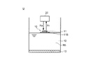
- FIG. 1 is a diagram showing a basic configuration of a detection system U according to the present disclosure.
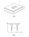
- FIG. 2 is a diagram showing a basic configuration of the sensor 10 according to the present disclosure.
- the detection system U has a sensor 10 having a predetermined reflection characteristic for electromagnetic waves (hereinafter, abbreviated as “reflection characteristic of the sensor 10”), and an electromagnetic wave Fa having a predetermined frequency transmitted to the sensor 10. It is configured to include a reader 20 that detects the reflection characteristic of the sensor 10 by receiving the reflected wave Fr from the sensor 10.
- the reader 20 is arranged in a fixed state at a position spaced apart from the sensor 10 by several meters so as to face the front surface of the sensor 10, for example.
- the detection system U detects a change in the state of the sensor 10 (that is, an environmental change to be detected by the sensor 10) based on the change in the reflection characteristic of the sensor 10.
- the sensor 10 includes an antenna unit 11, an isolation layer 12, and a back surface reflection material 13 in order from the front side.
- the antenna part 11 is a metal pattern formed on the base material 11B.
- the antenna part 11 is formed in a strip shape by a metal pattern, for example, and has a resonance structure that resonates when irradiated with an electromagnetic wave Fa having a predetermined frequency.
- the antenna unit 11 absorbs an electromagnetic wave Fa having a frequency matching the resonance frequency of itself (when the frequency of the electromagnetic wave Fa is f0 in FIG. 1) and is irradiated with an electromagnetic wave Fa having other frequencies, for example. Reflects the electromagnetic wave Fa.
- the resonance frequency of the antenna part 11 is determined by the shape (mainly the length) of the metal pattern forming the antenna part 11. Generally, when the maximum length of such an antenna is 1 / 2 ⁇ of the frequency of the electromagnetic wave, the antenna resonates, and an absorption peak that causes the intensity of the reflected wave at the frequency corresponding to the antenna length to decrease appears.
- the antenna section 11 may be formed by only one antenna element, but it is preferable that the antenna section 11 be formed by a plurality of antenna elements in order to increase the strength of the reflected wave Fr.
- the antenna part 11 is formed by, for example, a plurality of antenna elements having different lengths so that the sensor 10 has a plurality of resonance frequencies. Thereby, the detection accuracy of the reflection characteristic of the sensor 10 in the reader 20 can be improved.
- the method of forming the antenna portion 11 on the base material 11B may be an arbitrary method such as a printing method. Further, as the material of the antenna unit 11, a metal material such as copper, silver, gold, or aluminum is used. When the antenna part 11 is made to be stretchable, it is desirable to use a metal material containing a binder or the like as the material of the antenna part 11.
- the base material 11B on which the antenna part 11 is formed a material having electromagnetic wave permeability such as paper or resin is used.
- the shape of the base material 11B is not limited to the plate-like shape, and may be a curved shape or a cylindrical shape.
- the antenna unit 11 may be directly formed on an article such as a packaging material or a container.
- the base material 11B may be the object itself detected by the sensor 10.
- the isolation layer 12 is an insulating material or a space in which an object is not placed, and is disposed between the antenna unit 11 and the back reflector 13, and insulates between the antenna unit 11 and the back reflector 13.
- the resonance phenomenon is further amplified when the isolation layer 12 uses a space in which no object is placed (filled with air) or a low dielectric constant material such as foamed resin.
- the resonance peak changes significantly due to the change in the dielectric constant of the isolation layer 12.
- the back surface reflecting material 13 is arranged so as to face the antenna section 11 via the isolation layer 12 and reflects the electromagnetic wave Fa emitted to the sensor 10.
- the back surface reflecting material 13 is arranged, for example, in a position facing the antenna unit 11 in a plan view, over a region wider than the region in which the antenna unit 11 is formed.
- the back surface reflector 13 also functions to amplify the resonance phenomenon that occurs in the antenna unit 11. Specifically, when the back surface reflection material 13 is present, the resonance phenomenon that occurs in the antenna unit 11 also occurs between the antenna unit 11 and the back surface reflection material 13, and the resonance phenomenon is amplified. That is, the back surface reflector 13 increases the resonance peak when the resonance phenomenon occurs in the antenna unit 11.
- the back reflector 13 is arranged, for example, at a position where the distance from the antenna unit 11 is 0.01 mm to 1000 mm. Within this range, an electromagnetic field is likely to be generated between the antenna unit 11 and the back surface reflector 13, and the resonance phenomenon in the sensor 10 can be effectively amplified.
- a reflection wave Fr generated by the sensor 10 at the time of resonance and a reflection wave Fr generated by the sensor 10 at the time of non-resonance are provided.
- the contrast of the intensity of the reflected wave Fr can be increased.
- the resonance phenomenon is amplified when a material having a property of reflecting electromagnetic waves such as a metal material such as silver, gold, copper, or aluminum is used as the back surface reflector 13.
- the resonance peak changes significantly due to changes in the characteristics of reflecting electromagnetic waves due to changes in the area of the back surface reflector 13 in the area facing the antenna unit 11.
- the senor 10 is configured such that the state of any of the antenna unit 11, the isolation layer 12, and the back surface reflection material 13 is linked to the change in the state of the detection target (details will be described later). Then, the sensor 10 causes the reader 20 to detect the change in the state of the detection target by the change in the reflection characteristic of the reflected wave Fr generated when the reader 20 emits the electromagnetic wave Fa.
- the reflection characteristic of the sensor 10 indicating the state of the detection target is typically determined by the intensity of the reflected wave Fr of the sensor 10 generated when the reader 20 is irradiated with the electromagnetic wave Fa or the resonance frequency of the sensor 10. , Prescribed.
- the reader 20 includes a transmitter 21, a receiver 22, a state detector 23, and a controller 24.
- the transmitter 21 transmits an electromagnetic wave Fa having a predetermined frequency to the sensor 10.
- the transmission unit 21 is configured to include, for example, a transmission antenna and an oscillator.
- the transmitter 21 transmits, for example, a sinusoidal electromagnetic wave Fa having a peak intensity at a single frequency. Then, the transmission unit 21 temporally changes the transmission frequency of the electromagnetic wave Fa transmitted from the transmission antenna, and performs frequency sweep within a preset predetermined frequency band. Then, when the resonance frequency of the sensor 10 matches the transmission frequency of the electromagnetic wave Fa transmitted by the transmission unit 21, it is detected as a change in the intensity of the reflected wave Fr generated by the sensor 10.
- the frequency band of the electromagnetic wave Fa transmitted by the transmitter 21 is, for example, the millimeter wave band or the giga wave band.
- the receiving unit 22 receives the reflected wave Fr from the sensor 10 generated when the transmitting unit 21 transmits the electromagnetic wave Fa.
- the reception unit 22 is configured to include, for example, a reception antenna and a network analyzer. Then, the receiving unit 22 detects the reflection characteristic of the sensor 10 by the S parameter obtained from the intensity of the reflected wave Fr and the like.
- the state detection unit 23 compares the reflection characteristic of the sensor 10 at this time, which is grasped from the reflected wave Fr received by the reception unit 22, with the reflection characteristic of the sensor 10 stored in advance as the reference data 23D, and the comparison result.
- the state of the sensor 10 is detected based on
- the state detection unit 23 determines, for example, based on the comparison result, how much the resonance frequency of the sensor 10 or the intensity of the reflected wave Fr generated by the sensor 10 has changed from the value indicated by the reference data 23D.
- the state of the sensor 10 is detected by the calculation.
- the reference data 23D is data for converting the reflection characteristics of the sensor 10 at the present time into the current state of the sensor 10 (that is, the state of the detection target object).
- the reference data 23D may be data associating the state of the sensor 10 with the reflection characteristic of the sensor 10, and may be set based on the reflection characteristic of the sensor 10 that is grasped in advance, for example. It may be set based on the reflection characteristic of the sensor 10 detected before the time.
- reference data 23D for example, information on the intensity of the reflected wave for each frequency is stored as information on the reflection characteristic of the sensor 10. Then, in the reference data 23D, for example, the shift amount of the resonance frequency of the sensor 10 and the state change amount of the detection target are stored in association with each other. Further, in the reference data 23D, for example, the variation amount of the reflected wave intensity at the resonance frequency of the sensor 10 and the variation amount of the state of the detection target are stored in association with each other.
- the control unit 24 controls the reader 20 as a whole.
- the control unit 24 causes the transmission unit 21, the reception unit 22, and the state detection unit 23 to execute the above-described processing at predetermined intervals in order to sequentially monitor the state of the detection target object.
- the transmission unit 21, the reception unit 22, the state detection unit 23, and the control unit 24 are composed of, for example, a CPU, a ROM, a RAM, and the like. Then, a part or all of the above-mentioned transmission unit 21, reception unit 22, state detection unit 23, and control unit 24 are realized by the CPU referring to the control program and various data. However, a part or all of each function may be realized by a process by a DSP or a process by a dedicated hardware circuit (for example, ASIC) instead of or together with the process by the CPU.
- a DSP digital signal processor
- ASIC dedicated hardware circuit
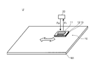
- FIG. 5 is a figure which shows an example of a structure of the detection system U which concerns on 1st Embodiment.
- the sensor 10 is attached to an object to be detected so that it can expand and contract. Then, the reader 20 detects a change in the resonance frequency of the sensor 10 or a change in the intensity of the reflected wave Fr from the sensor 10 due to the expansion and contraction of the antenna unit 11.
- FIG. 3A shows a mode in which the antenna section 11 expands and contracts in the longitudinal direction
- FIG. 3B schematically shows a mode in which the reflection characteristic of the sensor 10 changes when the antenna section 11 contracts in the longitudinal direction
- 4A shows a mode in which the antenna section 11 expands and contracts in the width direction
- FIG. 4B schematically shows a mode in which the reflection characteristic of the sensor 10 changes when the antenna section 11 extends in the width direction. ..
- the resonance frequency of the sensor 10 changes from the resonance frequency before expansion and contraction to the resonance frequency according to the length of the antenna unit 11. shift.
- the resonance frequency of the sensor 10 shifts to the low frequency side (for example, shifts from the frequency f0 to the frequency f1 as shown in FIG. 3B).
- the area where the antenna part 11 and the back surface reflecting member 13 face each other changes, so that the reflected wave Fr from the sensor 10 is changed.
- Strength changes from that before expansion and contraction.
- the intensity of the reflected wave Fr from the sensor 10 increases (for example, as shown in FIG. 4B, the intensity increases from I0 to I1).
- the reader 20 can detect the shape change of the object to which the sensor 10 is attached by detecting the reflection characteristic (resonance frequency or intensity) of the sensor 10 when transmitting the electromagnetic wave Fa to the sensor 10. .. At this time, the reader 20 detects expansion and contraction in the antenna unit 11 by comparing the detected reflection characteristic of the sensor 10 with the reflection characteristic of the sensor 10 stored in the reference data 23D. That is, according to the detection system U according to the present embodiment, for example, a shape change detection system can be configured.
- each of the antenna unit 11, the isolation layer 12, and the back surface reflector 13 is made of a material that can be expanded and contracted so as to expand and contract in accordance with the expansion and contraction of the object N1.
- the antenna unit 11 may be directly formed on the front surface of the object N1 to be detected, and the back surface reflecting material 13 may be arranged on the back surface side of the object N1 to be detected. In that case, only the antenna part 11 needs to be expandable.
- the isolation layer 12 and the back surface reflection material 13 are provided so that the reflection characteristics of the sensor 10 do not change due to changes in elements other than expansion and contraction of the antenna unit 11. It is configured in a manner that does not change the state.
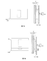
- 6 and 7 are diagrams showing the configuration of a detection system U according to a modified example of the present embodiment.
- the detection antenna section 11X is arranged so as to face the antenna section 11 of the sensor 10, and the base material 11B on which the antenna section 11 is formed and the detection antenna section 11X.
- the positional deviation is detected between the base material 11BX and the base material 11BX.
- the reader 20 when the positional displacement occurs between the base material 11B and the base material 11BX, the area of the opposing region between the antenna unit 11 and the detection antenna unit 11X changes, and It is detected that the reflection characteristics of the sensor 10 change in accordance with the above.
- 6A and 6B show a mode in which the positional relationship between the antenna unit 11 and the detection antenna unit 11X is displaced along the width direction of the antenna unit 11.
- the upper diagram and the lower diagram show a side view and a plan view of the detection system U, respectively.
- the change in the positional relationship between the antenna unit 11 and the detection antenna unit 11X is expressed as a change in the intensity of the reflected wave Fr from the sensor 10, as in the mode shown in FIG.
- 7A and 7B show a mode in which the positional relationship between the antenna unit 11 and the detection antenna unit 11X is displaced along the longitudinal direction of the antenna unit 11.
- the upper diagram and the lower diagram show a side view and a plan view of the detection system U, respectively.
- the change in the positional relationship between the antenna unit 11 and the detection antenna unit 11X is expressed as a change in the resonance frequency from the sensor 10, as in the mode shown in FIG.
- the position of the base material 11B or the base material 11BX is detected from the change in the reflection characteristic of the sensor 10 with the position of the base material 11B or the base material 11BX as the detection target. can do.
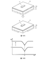
- FIG. 8 is a diagram showing the configuration of the sensor 10 according to the second embodiment.
- FIG. 9 is a figure which shows an example of a structure of the detection system U which concerns on 2nd Embodiment.
- the isolation layer 12 is configured so that an object to be detected can enter and leave the isolation layer 12.
- the isolation layer 12 is formed of, for example, a space that communicates with the outside, and is arranged in a state in which an object to be detected can enter and leave the space.
- the object to be detected entering and leaving the isolation layer 12 is not limited to a solid and may be a liquid or a granular material.
- the reader 20 changes the dielectric constant of the isolation layer 12 when an object is carried in or out of the isolation layer 12 or an object is carried out of or out of the isolation layer 12. To detect. At this time, a change in the dielectric constant of the isolation layer 12 is detected as a change in the resonance frequency of the sensor 10.
- FIG. 8A shows a mode in which the dielectric constant of the isolation layer 12 changes
- FIG. 8B schematically shows a mode in which the reflection characteristic of the sensor 10 changes when the dielectric constant of the isolation layer 12 increases. ..
- the resonance frequency of the antenna unit 11 changes due to the wavelength shortening effect of the isolation layer 12. Therefore, the resonance frequency of the sensor 10 shifts to the resonance frequency according to the dielectric constant of the isolation layer 12. It is known that such a wavelength shortening effect generally increases as the dielectric constant of the dielectric adjacent to the antenna unit 11 increases. Therefore, for example, when the dielectric constant of the isolation layer 12 increases, the resonance frequency of the sensor 10 shifts to the low frequency side (for example, shifts from the frequency f0 to the frequency f1 as shown in FIG. 8B). ..
- the reader 20 can detect the state change in the isolation layer 12 by detecting the reflection characteristic (resonance frequency or intensity) of the sensor 10.
- FIGS. 9A and 9B show a mode in which the isolation layer 12 is configured as a storage space for storing an object (for example, a medicine bag) N2.
- the reader 20 changes the state of the object N2 in the storage space formed by the isolation layer 12 from the inside of the isolation layer 12 due to the change in the dielectric constant of the isolation layer 12 (for example, the state of the drug in the medicine bag is reduced). (Decrease in quantity) is detected.
- the reader 20 detects the ratio of the object to be detected and the air in the isolation layer 12 as the dielectric constant.
- an article management system can be configured.
- the antenna portion 11 and the back surface reflection material 13 are arranged so that the reflection characteristics of the sensor 10 do not change due to changes in elements other than the change in the dielectric constant of the isolation layer 12. Is configured in such a manner that the state does not change.
- FIG. 10 is a diagram showing the configuration of the detection system U according to the first modification.
- the detection system U according to Modification 1 differs from the above-described embodiment in that the detection target is the liquid N3 that penetrates into the isolation layer 12.
- the isolation layer 12 is made of a liquid absorbing material, and the liquid N3 from around the sensor 10 can enter. Then, the reader 20 according to the present modification detects the state in which the liquid N3 has entered the isolation layer 12 due to the change in the dielectric constant of the isolation layer 12 (here, the liquid absorbing material).
- FIG. 11 is a diagram showing the configuration of the detection system U according to the second modification.
- the detection system U according to Modification 2 differs from the above-described embodiment in that the detection target is the density of the particle objects N4 flowing in the isolation layer 12.
- the isolation layer 12 is formed as a space inside the pipe through which gas flows.
- the antenna portion 11 of the sensor 10 and the back surface reflector 13 are arranged on one side and the other side of the space inside the pipe.
- the reader 20 according to the present modification detects the change in the dielectric constant of the isolation layer 12 based on the change in the resonance frequency of the reflected wave Fr from the sensor 10. Then, the reader 20 according to the present modification detects the density of the particle object N4 flowing in the isolation layer 12 from the change in the dielectric constant of the isolation layer 12.
- FIG. 12 is a diagram showing the configuration of the sensor 10 according to the third embodiment.
- FIG. 13 is a figure which shows an example of a structure of the detection system U which concerns on 3rd Embodiment.
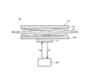
- the thickness of the isolation layer 12 (that is, the distance between the antenna unit 11 and the back surface reflector 13) is variable.
- the antenna unit 11 and the back surface reflector 13 are configured so that their positions change above or below the object to be detected in accordance with the change in the thickness of the object.
- the reader 20 detects a change in the intensity of the reflected wave Fr from the sensor 10 that accompanies a change in the thickness of the isolation layer 12.
- FIG. 12A shows an aspect in which the thickness of the isolation layer 12 changes
- FIG. 12B schematically shows an aspect in which the reflection characteristic of the sensor 10 changes when the thickness of the isolation layer 12 increases.
- the degree of the resonance phenomenon between the antenna unit 11 and the back reflector 13 changes.
- the degree of such a resonance phenomenon generally becomes maximum when the distance between the antenna unit 11 and the back surface reflection material 13 is a predetermined distance, and as the distance between the antenna unit 11 and the back surface reflection material 13 increases from the predetermined distance. Get smaller. Therefore, for example, when the thickness of the isolation layer 12 approaches a predetermined distance at which the degree of the resonance phenomenon between the antenna portion 11 and the back surface reflection material 13 increases, the intensity of the reflected wave Fr from the sensor 10 is reduced. , (Eg, increasing from intensity I0 to intensity I1 as shown in FIG. 12B).
- the reader 20 can detect the thickness of the isolation layer 12 (here, the liquid level of the liquid) by detecting the reflection characteristic of the sensor 10 (here, the intensity of the reflected wave Fr).
- FIG. 13 shows, as an example of the detection system U according to this embodiment, a mode in which the isolation layer 12 is composed of the liquid N5 filled in the container.
- the antenna portion 11 of the sensor 10 is arranged in a floating state on the surface of the liquid N5 filled in the container, and the back surface reflecting material 13 is arranged on the bottom surface of the container.
- the reader 20 detects the thickness of the isolation layer 12, that is, the liquid level of the liquid N5 filling the isolation layer 12 from the change in the intensity of the reflected wave Fr from the sensor 10. That is, according to the detection system U according to the present embodiment, for example, a liquid level management system can be configured.
- the antenna portion 11 and the back surface reflection material 13 are arranged so that the reflection characteristics of the sensor 10 do not change due to changes in elements other than the change in the thickness of the isolation layer 12. Is configured in such a manner that the state does not change.
- FIG. 14 and 15 are diagrams showing the configuration of the sensor 10 according to the fourth embodiment.
- FIG. 16 is a figure which shows an example of a structure of the detection system U which concerns on 4th Embodiment.
- the back surface reflector 13 of the sensor 10 according to the present embodiment is attached to an object to be detected, and an area facing the antenna section 11 (an area facing the antenna section 11 and its position, depending on the position of the object to be detected)
- An area including a peripheral region (hereinafter referred to as “antenna facing region”) is configured to be variable.
- the reader 20 detects a change in the area of the antenna facing area of the back reflector 13 of the sensor 10 based on the change in the intensity of the reflected wave Fr from the sensor 10.
- FIG. 14A shows a mode in which the area of the antenna facing area of the back surface reflecting material 13 changes by cutting off a part of the back surface reflecting material 13, and FIG. 14B shows the area of the antenna facing area of the back surface reflecting material 13 decreases.
- the mode of change of the reflection characteristic of the sensor 10 in the case of performing is shown typically.
- FIG. 15A shows a mode in which the area of the antenna facing area of the back surface reflecting material 13 changes as the back surface reflecting material 13 moves
- FIG. 15B shows the case where the area of the antenna facing area of the back surface reflecting material 13 increases.
- the mode of change of the reflection characteristic of the sensor 10 is schematically shown.
- the reader 20 can detect the state change of the back surface reflecting material 13 by detecting the intensity of the reflected wave Fr from the sensor 10.
- the back surface reflection material 13 of the sensor 10 is integrally configured with the detection target object (for example, individual medicine) N6, and the back surface reflection material 13 is formed. Shows a mode configured to be able to leave together with the detection target object N6. 16A and 16B, the reader 20 detects the number of objects N6 to be detected that have left the sensor 10 based on the change in the intensity of the reflected wave Fr from the sensor 10. That is, according to the detection system U according to the present embodiment, for example, a medication management system can be configured.
- the antenna portion 11 and the isolation portion are arranged so that the reflection characteristics of the sensor 10 do not change due to changes in elements other than the area of the antenna facing region of the back surface reflector 13.
- Layer 12 is constructed in a manner that does not change state.
- FIG. 17 is a diagram showing an example of the configuration of the detection system U according to the fifth embodiment.
- the detection system U includes a plurality of sensors 10a, 10b, 10c having resonance frequencies different from each other, and the reader 20 is configured to detect a state change of each sensor 10a, 10b, 10c separately. There is.
- Each sensor (here, either 10a, 10b, or 10c) according to the present embodiment is adjusted by adjusting the length of the antenna units 11a, 11b, and 11c in the longitudinal direction. 10b or 10c) or a resonance frequency different from the above. That is, each sensor 10a, 10b, 10c constitutes identification information for distinguishing from another sensor (here, any of 10a, 10b, 10c) by its own resonance frequency. And each sensor 10a, 10b, 10c detects each different state change.
- Each sensor 10a, 10b, 10c according to the present embodiment is configured similarly to the sensor 10 described in the fourth embodiment. Then, the sensors 10a, 10b, 10c are provided for each of the plurality of detection target objects (for example, medicines) N7, N8, N9, and can monitor the detachment state of each of the detection target objects N7, N8, N9. ..
- the sensors 10a, 10b, and 10c have the isolation layer 12 and the base material 11B in common, and by the different antenna parts 11a, 11b, and 11c, and the different back surface reflection materials 13a, 13b, and 13c, respectively. ,It is configured.
- the reader 20 irradiates each sensor 10a, 10b, 10c with an electromagnetic wave Fa and detects the reflection characteristic of each sensor 10a, 10b, 10c. Then, the reader 20 compares the detected reflection characteristics of the respective sensors 10a, 10b, 10c with the reflection characteristics of the respective sensors 10a, 10b, 10c indicated by the reference data 23D, and compares the respective reflection characteristics of the respective sensors 10a, 10b, 10c. Detect the condition.
- the reader 20 identifies the state of each sensor 10a, 10b, 10c based on the resonance frequency of each sensor 10a, 10b, 10c. That is, when any one of the sensors 10a, 10b, 10c is detached, the reader 20 detects a state in which the intensity of the reflected wave Fr at the resonance frequency corresponding to the sensor decreases.
- one reader 20 can individually manage the states of a plurality of detection target objects.
- the mode in which the states of the plurality of detection target objects are individually managed by using the plurality of sensors 10a, 10b, and 10c having mutually different resonance frequencies are the first to third embodiments. Of course, it can also be applied to the sensor 10 shown.
- the detection system U includes the antenna unit 11 formed of the metal pattern, and the back surface reflection member 13 that is disposed facing the antenna unit 11 via the isolation layer 12.
- the sensor 10 transmits the electromagnetic wave Fa to the sensor 10, receives the reflected wave Fr thereof, and compares the reflection characteristic of the sensor 10 grasped from the reflected wave Fr with the reflection characteristic of the sensor 10 stored in advance. By doing so, the reader 20 for detecting the state change of the sensor 10 is provided.
- the detection system U it is possible to accurately detect the change in the reflection characteristic of the sensor 10, and thereby the change in the state of the object to be detected by the sensor 10 or the vicinity of the object. It is possible to detect changes in the environment with high accuracy.
- the detection system U may detect a state where a part of the antenna unit 11 is peeled off or a state where the antenna unit 11 is attached.
- the detection system U may detect changes in the material forming the isolation layer 12 and the material forming the back surface reflecting material 13.
- the antenna unit 11 used in the detection system U reflects when an electromagnetic wave Fa having a frequency matching its own resonance frequency is irradiated and is irradiated with an electromagnetic wave Fa having another frequency. May be of a type that absorbs the electromagnetic wave Fa. Also in this case, it is desirable that the back surface reflector 13 is arranged at a position where the distance from the antenna unit 11 is 0.01 mm to 1000 mm. Within this range, the back surface reflector 13 functions to amplify the reflected wave generated in the antenna unit 11.
- the detection system it is possible to detect a change in the state of an object or a change in the environment around the object with high accuracy.
Landscapes
- Physics & Mathematics (AREA)
- Engineering & Computer Science (AREA)
- General Physics & Mathematics (AREA)
- Theoretical Computer Science (AREA)
- Health & Medical Sciences (AREA)
- Toxicology (AREA)
- Electromagnetism (AREA)
- General Health & Medical Sciences (AREA)
- Artificial Intelligence (AREA)
- Computer Vision & Pattern Recognition (AREA)
- Geophysics And Detection Of Objects (AREA)
- Length-Measuring Devices Using Wave Or Particle Radiation (AREA)
Abstract
L'invention concerne un système de détection qui est pourvu : d'un capteur (10) comprenant une partie d'antenne (11) formée au moyen d'un motif métallique, et d'un matériau réfléchissant de surface arrière (13) disposée en regard de la partie d'antenne (11) avec une couche d'isolation (12) interposée entre celles-ci ; et un lecteur (20) qui transmet des ondes électromagnétiques (Fa) vers le capteur (10) et reçoit des ondes réfléchies (Fr) en provenance de celui-ci, et qui détecte un changement d'état dans le capteur (10) par comparaison d'une caractéristique de réflexion du capteur (10) déterminée à partir des ondes réfléchies (Fr) avec une caractéristique de réflexion pré-mémorisée du capteur (10).
Priority Applications (4)
| Application Number | Priority Date | Filing Date | Title |
|---|---|---|---|
| CN201980070504.1A CN113039558B (zh) | 2018-11-02 | 2019-10-30 | 检测系统、以及读取器 |
| US17/283,637 US11630963B2 (en) | 2018-11-02 | 2019-10-30 | Detecting system, and reader |
| EP19878052.0A EP3876153B1 (fr) | 2018-11-02 | 2019-10-30 | Système de détection et lecteur |
| JP2020553985A JP7405092B2 (ja) | 2018-11-02 | 2019-10-30 | 検出システム、及びリーダー |
Applications Claiming Priority (2)
| Application Number | Priority Date | Filing Date | Title |
|---|---|---|---|
| JP2018207687 | 2018-11-02 | ||
| JP2018-207687 | 2018-11-02 |
Publications (1)
| Publication Number | Publication Date |
|---|---|
| WO2020090904A1 true WO2020090904A1 (fr) | 2020-05-07 |
Family
ID=70463744
Family Applications (1)
| Application Number | Title | Priority Date | Filing Date |
|---|---|---|---|
| PCT/JP2019/042609 WO2020090904A1 (fr) | 2018-11-02 | 2019-10-30 | Système de détection et lecteur |
Country Status (5)
| Country | Link |
|---|---|
| US (1) | US11630963B2 (fr) |
| EP (1) | EP3876153B1 (fr) |
| JP (1) | JP7405092B2 (fr) |
| CN (1) | CN113039558B (fr) |
| WO (1) | WO2020090904A1 (fr) |
Cited By (5)
| Publication number | Priority date | Publication date | Assignee | Title |
|---|---|---|---|---|
| WO2021215221A1 (fr) * | 2020-04-24 | 2021-10-28 | コニカミノルタ株式会社 | Système de détection d'état |
| WO2022239427A1 (fr) * | 2021-05-10 | 2022-11-17 | コニカミノルタ株式会社 | Système de détection d'état |
| WO2022239425A1 (fr) * | 2021-05-10 | 2022-11-17 | コニカミノルタ株式会社 | Système de détection d'état |
| WO2022254853A1 (fr) * | 2021-06-03 | 2022-12-08 | コニカミノルタ株式会社 | Système d'inspection et procédé d'inspection |
| US11630963B2 (en) * | 2018-11-02 | 2023-04-18 | Konica Minolta, Inc. | Detecting system, and reader |
Citations (5)
| Publication number | Priority date | Publication date | Assignee | Title |
|---|---|---|---|---|
| JPH1125370A (ja) * | 1997-07-04 | 1999-01-29 | Sensor Technos Kk | 定置物品監視装置 |
| JP2001134726A (ja) | 1999-11-01 | 2001-05-18 | Sensor Technos Kk | サニタリー用センサーシステム |
| JP2001161732A (ja) * | 1999-09-27 | 2001-06-19 | Matsushita Electric Works Ltd | おむつ交換頃合センサー及びおむつ交換頃合検知装置 |
| JP2016167279A (ja) * | 2010-04-08 | 2016-09-15 | アクセス ビジネス グループ インターナショナル リミテッド ライアビリティ カンパニー | POS(point of sale)誘導性システムと方法 |
| JP2018207687A (ja) | 2017-06-06 | 2018-12-27 | 東日本旅客鉄道株式会社 | 自動列車防護システム |
Family Cites Families (11)
| Publication number | Priority date | Publication date | Assignee | Title |
|---|---|---|---|---|
| JP4164423B2 (ja) * | 2003-08-29 | 2008-10-15 | キヤノン株式会社 | センシング部とポインティングデバイスとを含み構成される装置 |
| JP4747750B2 (ja) * | 2005-09-13 | 2011-08-17 | 大日本印刷株式会社 | 環境変化検知システム |
| JP2007110256A (ja) * | 2005-10-11 | 2007-04-26 | Matsushita Electric Ind Co Ltd | フェーズドアレイアンテナ |
| JP2011058836A (ja) * | 2009-09-07 | 2011-03-24 | Alps Electric Co Ltd | 無線センサ装置 |
| JP2015017835A (ja) * | 2013-07-09 | 2015-01-29 | 京セラ株式会社 | 距離センサおよび浴室用異常報知システム |
| US11209536B2 (en) * | 2014-05-02 | 2021-12-28 | The Board Of Trustees Of The Leland Stanford Junior University | Method and apparatus for tracking motion using radio frequency signals |
| CA2957057A1 (fr) * | 2014-08-04 | 2016-02-11 | Avery Dennison Corporation | Etiquette de suivi de temps-temperature |
| SG11201701073RA (en) * | 2014-08-22 | 2017-04-27 | Fujitsu Ltd | State estimating method, state estimating system, clothing, and monitoring system |
| KR20170106837A (ko) * | 2016-03-14 | 2017-09-22 | 엘지전자 주식회사 | 요당 검출용 전계효과 트랜지스터 |
| KR20180071802A (ko) * | 2016-12-20 | 2018-06-28 | 삼성전자주식회사 | 이미지 센서 |
| US11630963B2 (en) * | 2018-11-02 | 2023-04-18 | Konica Minolta, Inc. | Detecting system, and reader |
-
2019
- 2019-10-30 US US17/283,637 patent/US11630963B2/en active Active
- 2019-10-30 WO PCT/JP2019/042609 patent/WO2020090904A1/fr unknown
- 2019-10-30 CN CN201980070504.1A patent/CN113039558B/zh active Active
- 2019-10-30 JP JP2020553985A patent/JP7405092B2/ja active Active
- 2019-10-30 EP EP19878052.0A patent/EP3876153B1/fr active Active
Patent Citations (5)
| Publication number | Priority date | Publication date | Assignee | Title |
|---|---|---|---|---|
| JPH1125370A (ja) * | 1997-07-04 | 1999-01-29 | Sensor Technos Kk | 定置物品監視装置 |
| JP2001161732A (ja) * | 1999-09-27 | 2001-06-19 | Matsushita Electric Works Ltd | おむつ交換頃合センサー及びおむつ交換頃合検知装置 |
| JP2001134726A (ja) | 1999-11-01 | 2001-05-18 | Sensor Technos Kk | サニタリー用センサーシステム |
| JP2016167279A (ja) * | 2010-04-08 | 2016-09-15 | アクセス ビジネス グループ インターナショナル リミテッド ライアビリティ カンパニー | POS(point of sale)誘導性システムと方法 |
| JP2018207687A (ja) | 2017-06-06 | 2018-12-27 | 東日本旅客鉄道株式会社 | 自動列車防護システム |
Cited By (5)
| Publication number | Priority date | Publication date | Assignee | Title |
|---|---|---|---|---|
| US11630963B2 (en) * | 2018-11-02 | 2023-04-18 | Konica Minolta, Inc. | Detecting system, and reader |
| WO2021215221A1 (fr) * | 2020-04-24 | 2021-10-28 | コニカミノルタ株式会社 | Système de détection d'état |
| WO2022239427A1 (fr) * | 2021-05-10 | 2022-11-17 | コニカミノルタ株式会社 | Système de détection d'état |
| WO2022239425A1 (fr) * | 2021-05-10 | 2022-11-17 | コニカミノルタ株式会社 | Système de détection d'état |
| WO2022254853A1 (fr) * | 2021-06-03 | 2022-12-08 | コニカミノルタ株式会社 | Système d'inspection et procédé d'inspection |
Also Published As
| Publication number | Publication date |
|---|---|
| CN113039558B (zh) | 2023-11-03 |
| EP3876153A4 (fr) | 2022-03-02 |
| JPWO2020090904A1 (ja) | 2021-09-30 |
| US11630963B2 (en) | 2023-04-18 |
| US20210390274A1 (en) | 2021-12-16 |
| EP3876153A1 (fr) | 2021-09-08 |
| EP3876153B1 (fr) | 2023-08-30 |
| JP7405092B2 (ja) | 2023-12-26 |
| CN113039558A (zh) | 2021-06-25 |
Similar Documents
| Publication | Publication Date | Title |
|---|---|---|
| WO2020090904A1 (fr) | Système de détection et lecteur | |
| US9590306B2 (en) | Electromagnetic enhancement and decoupling | |
| US8842038B2 (en) | High frequency mode generator for radar level gauge | |
| EP2851994B1 (fr) | Antenne de capteur radar avec élément antireflet | |
| JP7147771B2 (ja) | 非接触読み取りタグ、非接触読み取りタグの製造方法、判別装置、および識別情報読み取り方法 | |
| JP2013528966A (ja) | 非線形共振センサ及び方法 | |
| EA004579B1 (ru) | Устройство для определения уровня загружаемого материала в резервуаре | |
| JP6135358B2 (ja) | アンテナ及びアンテナの製造方法 | |
| US7782210B2 (en) | Resonance tag | |
| EP4081424B1 (fr) | Systeme de detection de presence pour siege | |
| US11816523B2 (en) | RF tag and RF tag-equipped conductor | |
| JP3331954B2 (ja) | 磁歪振動子検出装置、車両および交通システム | |
| Morris et al. | Embedded Aperture-Based FSS Sensor | |
| KR20190067975A (ko) | 마이크로 스트립 구조의 발진기를 가진 마이크로파 센서 | |
| JP2005265725A (ja) | シート状被測定物の材料判別装置及び材料判別方法 | |
| JPH07260944A (ja) | マイクロ波検査方法およびその装置 |
Legal Events
| Date | Code | Title | Description |
|---|---|---|---|
| 121 | Ep: the epo has been informed by wipo that ep was designated in this application |
Ref document number: 19878052 Country of ref document: EP Kind code of ref document: A1 |
|
| ENP | Entry into the national phase |
Ref document number: 2020553985 Country of ref document: JP Kind code of ref document: A |
|
| NENP | Non-entry into the national phase |
Ref country code: DE |
|
| ENP | Entry into the national phase |
Ref document number: 2019878052 Country of ref document: EP Effective date: 20210602 |