WO2020090422A1 - 映像表示装置 - Google Patents
映像表示装置 Download PDFInfo
- Publication number
- WO2020090422A1 WO2020090422A1 PCT/JP2019/040210 JP2019040210W WO2020090422A1 WO 2020090422 A1 WO2020090422 A1 WO 2020090422A1 JP 2019040210 W JP2019040210 W JP 2019040210W WO 2020090422 A1 WO2020090422 A1 WO 2020090422A1
- Authority
- WO
- WIPO (PCT)
- Prior art keywords
- display device
- projection
- unit
- video display
- image display
- Prior art date
- Legal status (The legal status is an assumption and is not a legal conclusion. Google has not performed a legal analysis and makes no representation as to the accuracy of the status listed.)
- Ceased
Links
Images


Classifications
-
- H—ELECTRICITY
- H04—ELECTRIC COMMUNICATION TECHNIQUE
- H04N—PICTORIAL COMMUNICATION, e.g. TELEVISION
- H04N13/00—Stereoscopic video systems; Multi-view video systems; Details thereof
- H04N13/30—Image reproducers
- H04N13/366—Image reproducers using viewer tracking
-
- G—PHYSICS
- G03—PHOTOGRAPHY; CINEMATOGRAPHY; ANALOGOUS TECHNIQUES USING WAVES OTHER THAN OPTICAL WAVES; ELECTROGRAPHY; HOLOGRAPHY
- G03B—APPARATUS OR ARRANGEMENTS FOR TAKING PHOTOGRAPHS OR FOR PROJECTING OR VIEWING THEM; APPARATUS OR ARRANGEMENTS EMPLOYING ANALOGOUS TECHNIQUES USING WAVES OTHER THAN OPTICAL WAVES; ACCESSORIES THEREFOR
- G03B21/00—Projectors or projection-type viewers; Accessories therefor
- G03B21/54—Accessories
- G03B21/56—Projection screens
- G03B21/60—Projection screens characterised by the nature of the surface
- G03B21/62—Translucent screens
-
- G—PHYSICS
- G03—PHOTOGRAPHY; CINEMATOGRAPHY; ANALOGOUS TECHNIQUES USING WAVES OTHER THAN OPTICAL WAVES; ELECTROGRAPHY; HOLOGRAPHY
- G03B—APPARATUS OR ARRANGEMENTS FOR TAKING PHOTOGRAPHS OR FOR PROJECTING OR VIEWING THEM; APPARATUS OR ARRANGEMENTS EMPLOYING ANALOGOUS TECHNIQUES USING WAVES OTHER THAN OPTICAL WAVES; ACCESSORIES THEREFOR
- G03B35/00—Stereoscopic photography
- G03B35/18—Stereoscopic photography by simultaneous viewing
- G03B35/20—Stereoscopic photography by simultaneous viewing using two or more projectors
-
- H—ELECTRICITY
- H04—ELECTRIC COMMUNICATION TECHNIQUE
- H04N—PICTORIAL COMMUNICATION, e.g. TELEVISION
- H04N13/00—Stereoscopic video systems; Multi-view video systems; Details thereof
- H04N13/30—Image reproducers
- H04N13/363—Image reproducers using image projection screens
-
- H—ELECTRICITY
- H04—ELECTRIC COMMUNICATION TECHNIQUE
- H04N—PICTORIAL COMMUNICATION, e.g. TELEVISION
- H04N13/00—Stereoscopic video systems; Multi-view video systems; Details thereof
- H04N13/30—Image reproducers
- H04N13/388—Volumetric displays, i.e. systems where the image is built up from picture elements distributed through a volume
- H04N13/393—Volumetric displays, i.e. systems where the image is built up from picture elements distributed through a volume the volume being generated by a moving, e.g. vibrating or rotating, surface
-
- H—ELECTRICITY
- H04—ELECTRIC COMMUNICATION TECHNIQUE
- H04N—PICTORIAL COMMUNICATION, e.g. TELEVISION
- H04N9/00—Details of colour television systems
- H04N9/12—Picture reproducers
- H04N9/31—Projection devices for colour picture display, e.g. using electronic spatial light modulators [ESLM]
- H04N9/3141—Constructional details thereof
- H04N9/3147—Multi-projection systems
-
- H—ELECTRICITY
- H04—ELECTRIC COMMUNICATION TECHNIQUE
- H04N—PICTORIAL COMMUNICATION, e.g. TELEVISION
- H04N9/00—Details of colour television systems
- H04N9/12—Picture reproducers
- H04N9/31—Projection devices for colour picture display, e.g. using electronic spatial light modulators [ESLM]
- H04N9/3141—Constructional details thereof
- H04N9/317—Convergence or focusing systems
-
- H—ELECTRICITY
- H04—ELECTRIC COMMUNICATION TECHNIQUE
- H04N—PICTORIAL COMMUNICATION, e.g. TELEVISION
- H04N9/00—Details of colour television systems
- H04N9/12—Picture reproducers
- H04N9/31—Projection devices for colour picture display, e.g. using electronic spatial light modulators [ESLM]
- H04N9/3191—Testing thereof
- H04N9/3194—Testing thereof including sensor feedback
Definitions
- the present disclosure relates to a video display device that displays a plurality of viewpoint videos.
- a technology that displays a stereoscopic image by displaying multiple images (viewpoint images) viewed from different viewpoints on the same screen. For example, by arranging a plurality of projectors on the circumference and arranging a screen that diffuses only in the vertical direction in the center part, projecting viewpoint images from each of the plurality of projectors on the screen at mutually different angles, There is a technique for displaying a stereoscopic image (see Patent Document 1). In this case, constituent elements such as a drive circuit, a projection optical system, and a display element, which form each projector, are arranged on the circumference.
- the size of the entire video display device increases due to the restrictions on the area occupied by the components of multiple projectors.
- the arrangement pitch between a plurality of projectors is determined by the size of each projector, and in terms of characteristics, the angular resolution, which is a factor that determines the display quality of stereoscopic images, is restricted.
- An image display device is configured such that at least a part thereof is rotatably movable, and a projection unit that emits projection light that forms at least one viewpoint image and a light collection unit that collects the projection light. And a diffusing member for diffusing the projection light so as to have a relatively narrow diffusion in the horizontal direction and a relatively wide diffusion in the vertical direction, a detection unit for detecting the viewpoint position of the observer, and at least one of the projection unit And a control unit that rotationally moves the unit to a position corresponding to the viewpoint position detected by the detection unit.
- projection light that forms at least one viewpoint video is emitted from a projection unit that is at least partially rotatable.
- the control unit rotationally moves at least a part of the projection unit to a position according to the viewpoint position detected by the detection unit.
- FIG. 1 is a top view schematically showing a configuration example of a video display device according to a first embodiment of the present disclosure. It is a side sectional view showing roughly an example of 1 composition of a video display concerning a 1st embodiment. It is explanatory drawing which shows an example of the suitable light ray diffusion distribution of the horizontal direction in the video display apparatus which concerns on 1st Embodiment.
- FIG. 6 is an explanatory diagram showing an example of characteristic parameters regarding a relationship between an observation distance and a viewpoint position in the video display device according to the first embodiment.
- FIG. 1 is a top view schematically showing a configuration example of a video display device according to a first embodiment of the present disclosure. It is a side sectional view showing roughly an example of 1 composition of a video display concerning a 1st embodiment. It is explanatory drawing which shows an example of the suitable light ray diffusion distribution of the horizontal direction in the video display apparatus which concerns on 1st Embodiment.
- FIG. 6 is an explanatory diagram showing an example of
- FIG. 8 is a characteristic diagram showing an example of values of main characteristic parameters when the optimum observation position is changed in the video display device according to the first embodiment.
- FIG. 7 is a characteristic diagram showing an example of values of main characteristic parameters when the horizontal diffusion angle is changed in the video display device according to the first embodiment.
- It is a top view which shows schematically the principal part of the example of 1 structure of the video display apparatus which concerns on 2nd Embodiment.
- It is explanatory drawing which shows an example of the characteristic parameter regarding the relationship of the observation distance and viewpoint position in the video display apparatus which concerns on 2nd Embodiment.
- It is a characteristic view which shows an example of the relationship between the viewing distance and the positions of the first and second projector modules in the video display device according to the second embodiment.
- FIG. 1 It is a top view which shows roughly the example of 1 structure of the video display apparatus which concerns on 6th Embodiment. It is sectional drawing which shows roughly one structural example of the transmissive cylindrical screen in the video display apparatus which concerns on 6th Embodiment. It is sectional drawing which shows roughly the equivalent structural example of the transmissive cylindrical screen in the video display apparatus which concerns on 6th Embodiment. It is a top view which shows roughly the example of 1 structure of the video display apparatus which concerns on 7th Embodiment. It is a side sectional view showing roughly an example of 1 composition of a video display concerning a 7th embodiment.
- FIG. 3 is a side sectional view schematically showing an example of the relationship between the projection elevation angle and the rotational movement direction of the projector module in the video display device according to the first embodiment.
- FIG. 21 is a side sectional view schematically showing an example of the relationship between the projection elevation angle and the rotational movement direction of the projector module in the video display device according to the seventh embodiment.
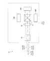
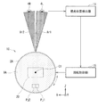
- FIG. 1 shows an outline of a video display device according to a comparative example.
- the video display device includes a plurality of projectors 100 arranged in an array on the circumference and a screen 200 having an anisotropic diffusion characteristic arranged in the center. An image is projected from each projector 100 toward the center to display a stereoscopic image.
- One projector 100 is, for example, a DMD (Digital Micromirror Device) type MEMS (Micro Electro Mechanical System) projector that generates a projected image by a plurality of two-dimensionally arranged movable mirrors.
- one projector 100 displays a two-dimensional image on the screen 200 by two-dimensionally scanning the laser light source with the MEMS mirror.
- one projector 100 emits video light for one viewpoint. Therefore, in order to display a plurality of viewpoint videos, the projectors 100 corresponding to the number of viewpoints are required, which results in a large-scale device as a whole.
- the base points of the projectors 100 are on the circumference, and it is difficult to reduce the size of the entire device even if the individual projectors 100 are downsized.
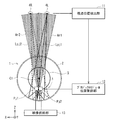
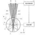
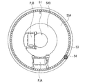
- FIG. 2 schematically illustrates a configuration example of the video display device 1 according to the first embodiment of the present disclosure when viewed from the top surface direction.
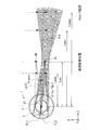
- FIG. 3 schematically shows a configuration example of a lateral cross section of the video display device 1. Note that, in FIG. 2 and the like, the X axis indicates the horizontal direction, the Y axis indicates the vertical direction, and the Z axis indicates the direction orthogonal to the X axis and the Y axis. The same applies to other drawings showing the first embodiment and drawings shown in other embodiments, which will be described later.
- the image display device 1 includes a reflective cylindrical screen 2, a circular rail 3 arranged on the inner peripheral side of the reflective cylindrical screen 2, a first projector module Pj1 arranged on the rail 3, and a first projector module Pj1. 2 projector modules Pj2.
- the image display device 1 further includes a housing 10 (FIG. 3) that houses the rail 3, the first projector module Pj1, and the second projector module Pj2.
- the image display device 1 further includes a viewpoint position detection unit 11, a projector module position control unit 12, and an image supply unit 13.
- the first projector module Pj1 and the second projector module Pj2 correspond to a specific but not limitative example of “projection unit” in the technology of the present disclosure.
- the reflective cylindrical screen 2 corresponds to a specific but not limitative example of “diffusion member” in the technique of the present disclosure.
- the viewpoint position detection unit 11 corresponds to a specific but not limitative example of “detection unit” in the technology of the present disclosure.
- the projector module position control unit 12 corresponds to a specific but not limitative example of “control unit” in the technology of the present disclosure.
- the viewpoint position detection unit 11 detects the viewpoint position of the observer (left eye 4L and right eye 4R).
- the viewpoint position detection unit 11 has, for example, a camera module, and detects at least the horizontal viewpoint position of the observer.
- the projector module position control unit 12 rotationally moves the first and second projector modules Pj1 and Pj2 to the positions corresponding to the viewpoint positions detected by the viewpoint position detection unit 11.
- the first and second projector modules Pj1 and Pj2 collectively configure a “projection unit” in the technology of the present disclosure.
- the first and second projector modules Pj1 and Pj2 are, for example, rotatably movable on the rail 3 as a whole.
- the central axis of the circular rail 3 substantially coincides with the central axis C1 of the reflective cylindrical screen 2.
- the first and second projector modules Pj1 and Pj2 are fixed to the rail 3 and the rail 3 itself is rotated to rotationally move the first and second projector modules Pj1 and Pj2. It may be allowed to.
- the circular rail 3 has a center of rotation that is hollow so that wiring can be arranged.
- the wiring referred to here includes, for example, electric wiring and optical communication wiring connected to the first and second projector modules Pj1 and Pj2.
- the circular rail 3 corresponds to a specific but not limitative example of “rotational drive mechanism section” in the technology of the present disclosure.
- Each of the first and second projector modules Pj1 and Pj2 includes, for example, a laser light source and a light modulation element that modulates light from the laser light source.
- Each of the first and second projector modules Pj1 and Pj2 can be configured by, for example, an LCOS (Liquid Crystal On Silicon) type projector, a DMD type MEMS projector, a single mirror type MEMS projector, or the like.
- Each of the first and second projector modules Pj1 and Pj2 emits projection light forming at least one viewpoint image.
- the first projector module Pj1 emits the first projection light Lpj1 that forms the viewpoint image for the left eye 4L.
- the second projector module Pj2 emits the second projection light Lpj2 that forms the viewpoint image for the right eye 4R.
- the video supply unit 13 supplies video signals corresponding to viewpoint videos for the left eye 4L and the right eye 4R to the first and second projector modules Pj1 and Pj2, respectively.
- the reflective cylindrical screen 2 is a diffusing member having an anisotropic diffusing property in which the light diffusing properties are different in the horizontal and vertical directions.
- the reflective cylindrical screen 2 has a cylindrical reflective surface on the inner peripheral surface.
- the cylindrical reflection surface of the reflection type cylindrical screen 2 acts as a condensing unit that condenses the first and second projection lights Lpj1 and Lpj2.
- the reflective cylindrical screen 2 is composed of, for example, a reflective holographic optical element (HOE).
- the reflection-type cylindrical screen 2 collects the first and second projection lights Lpj1 and Lpj2 toward the observer's viewpoint position on the cylindrical reflection surface while relatively narrowly diffusing in the horizontal direction and relatively in the vertical direction. Spread so as to be widely diffused.
- the cylindrical reflecting surface of the reflective cylindrical screen 2 corresponds to a specific example of “a light collecting unit” in the technique of the present disclosure.
- the first projector module Pj1 projects the first projection light Lpj1 toward the cylindrical reflecting surface formed on the inner peripheral surface of the reflective cylindrical screen 2. Further, the second projector module Pj2 projects the second projection light Lpj2 toward the cylindrical reflection surface of the reflection type cylindrical screen 2 at a position different from the first projection light Lpj1.
- the first projection light Lpj1 is diffused while being condensed by the reflection type cylindrical screen 2 while being diffused in the first projection area Ar1. Further, the second projection light Lpj2 is diffused while being condensed by the reflective cylindrical screen 2 while being diffused in the second projection area Ar2.
- the rotational movement positions of the first and second projector modules Pj1 and Pj2 are controlled by the projector module position control unit 12, and the proper positions are set according to the viewpoint position detected by the viewpoint position detection unit 11.
- the first and second projector modules Pj1 and Pj2 rotationally move about an axis substantially the same as the central axis C1 of the reflective cylindrical screen 2.
- the rotation angles of the first and second projector modules Pj1 and Pj2 are determined so that the respective focus positions of the first and second projection lights Lpj1 and Lpj2 and the positions of the left eye 4L and the right eye 4R substantially match. ..
- the first projection light Lpj1 is condensed toward the left eye 4L, for example.
- the second projection light Lpj2 is condensed, for example, toward the right eye 4R. It is preferable that the first and second projector modules Pj1 and Pj2 rotate and move on a plane such that the projection elevation angle ⁇ with respect to the cylindrical reflection surface of the reflection type cylindrical screen 2 becomes constant, as shown in FIG. 25 described later. ..
- FIG. 4 shows an example of an appropriate horizontal ray diffusion distribution in the image display device 1.
- the first and second projection lights Lpj1, from the first and second projector modules Pj1 and Pj2 are arranged so that the viewpoint images of the left eye 4L and the right eye 4 do not mix with each other. It is preferable to diffuse Lpj2 in the horizontal direction at an appropriate angle. For example, as shown in FIG. 4, in the reflection type cylindrical screen 2, it is preferable to diffuse the first and second projection lights Lpj1 and Lpj2 so as to have a diffusion distribution close to a rectangle in the horizontal direction.
- the reflection-type cylindrical screen 2 with a diffusion distribution characteristic having a relatively narrow angle in the horizontal direction (X direction in FIG. 4), it is possible to prevent crosstalk caused by mixing left and right viewpoint images. ..
- the reflection type cylindrical screen 2 is provided with a diffusion distribution characteristic such that the angle is wider than the horizontal direction, so that the viewpoint image can be observed at a wide angle in the vertical direction. It becomes possible to do.
- the cylindrical reflection surface of the reflection type cylindrical screen 2 is provided with a lens function as a light converging portion, but the focus position thereof is a position half the radius of the cylindrical reflection surface.
- the first and second projector modules Pj1 and Pj2 are arranged, for example, at positions slightly shifted to the central axis C1 side from the position of 1/2 of the radius of the cylindrical reflecting surface.
- the optimum observation position of the image display device 1 is determined by the positions of the first and second projector modules Pj1 and Pj2.
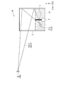
- FIG. 5 shows an example of characteristic parameters relating to the relationship between the observation distance and the viewpoint position in the video display device 1.
- the meanings of the symbols are as follows.
- Lcmax Allowable crosstalk limit distance
- Lmax Maximum allowable image missing distance
- Lmin Minimum allowable image missing distance
- Lop Optimal observation distance
- ⁇ conv Inter-view ray angle
- ⁇ fov Viewing angle (FOV (Field of View))
- ⁇ d Horizontal diffusion angle
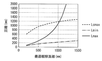
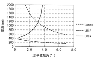
- FIG. 6 shows main characteristic parameters (the allowable crosstalk limit distance Lcmax, the maximum allowable image loss distance Lmax, and the minimum allowable image loss distance Lmin) when the optimum observation distance Lop (the optimum observation position) is changed in the image display device 1. ) Shows an example of the value of. Further, FIG. 7 shows an example of values of similar main characteristic parameters when the horizontal diffusion angle is changed in the video display device 1.
- FIG. 6 and 7 show values when the horizontal display size of the viewpoint image is 100 mm and the interocular distance is 65 mm. Further, FIG. 6 shows values when the horizontal diffusion angle ⁇ d is 3 °.
- the distance range in which the image deletion does not occur is the distance range (Lmax ⁇ ) between the image deletion allowable maximum distance Lmax and the image deletion allowable minimum distance Lmin. Lmin). Further, the distance range equal to or less than the allowable crosstalk limit distance Lcmax is the distance range in which crosstalk does not occur.
- the values of the characteristic parameters shown in FIGS. 5 to 7 are determined by the usage conditions.
- the left and right viewpoints are viewed from the projection unit (the first and second projector modules Pj1 and Pj2) that is rotatably movable. Since projection light that forms an image is emitted and the projection unit is rotationally moved to a position according to the viewpoint position, it is possible to perform stereoscopic image display with high display quality in a wide range without increasing the size of the configuration. It will be possible.
- FIG. 8 schematically shows a main part of a configuration example of the video display device 1A according to the second embodiment as viewed from the top surface direction.
- the first and second projector modules Pj1 and Pj2 are fixed in the direction (observation distance direction) orthogonal to the rotational movement direction. Further, the interval between the first and second projector modules Pj1 and Pj2 is fixed to a constant value.
- the first and second projector modules Pj1 and Pj2 are the first and second projector modules in the direction orthogonal to the rotational movement direction.
- the position Zpj of Pj1 and Pj2 is variable.
- the distance Xpj between the first and second projector modules Pj1 and Pj2 in the horizontal direction is variable.
- the emission positions of the first and second projection lights Lpj1 and Lpj2 from the first and second projector modules Pj1 and Pj2 can be adjusted. This makes it possible to adjust the respective focus positions (focus positions) of the first and second projection lights Lpj1 and Lpj2.
- the viewpoint position detection unit 11 detects, for example, the viewpoint position in the observation distance direction in addition to the horizontal direction of the observer.
- the projector module position control unit 12 rotationally moves the first and second projector modules Pj1 and Pj2 to the positions corresponding to the horizontal viewpoint positions detected by the viewpoint position detection unit 11, and at the same time, the viewpoint positions in the observation distance direction.
- the first and second projector modules Pj1 and Pj2 are moved to positions corresponding to.
- the projector module position control unit 12 determines that the focus positions of the first and second projection lights Lpj1 and Lpj2 correspond to the viewpoint positions in the observation distance direction detected by the viewpoint position detection unit 11.
- the position Zpj and the interval Xpj of the first and second projector modules Pj1 and Pj2 are controlled so that
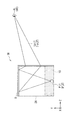
- FIG. 9 shows an example of characteristic parameters relating to the relationship between the observation distance Lo (observation position) and the viewpoint position in the video display device 1A.
- FIG. 10 shows an example of the relationship between the observation distance Lo and the positions Zpj of the first and second projector modules Pj1 and Pj2 in the image display device 1A.
- FIG. 11 shows an example of the relationship between the observation distance Lo and the interval Xpj between the first and second projector modules Pj1 and Pj2 in the image display device 1A.
- the optimum observation distance Lop is fixed to a constant value, and the distance that allows comfortable observation around the optimum observation position is limited. ..
- the video display device 1A according to the second embodiment by optimizing the position Zpj and the interval Xpj of the first and second projector modules Pj1 and Pj2 in accordance with the viewpoint position in the observation distance direction, It is possible to comfortably observe in a wide range not only in the horizontal direction but also in the observation distance direction.
- FIG. 12 schematically shows a main part of a configuration example of the video display device 1B according to the third embodiment as viewed from the top surface direction.
- FIG. 13 schematically shows a main part of a configuration example of a lateral cross section of the video display device 1B.
- the positions Zpj and the intervals Xpj of the first and second projector modules Pj1 and Pj2 are made variable so that the first and second projection lights Lpj1 and Lpj2. It is possible to adjust the respective focusing positions (focus positions) of the.
- the image display device 1B according to the third embodiment includes the condensing position adjusting lens 21 for adjusting the condensing positions of the first and second projection lights Lpj1 and Lpj2. ing.
- the first and second projector modules Pj1 and Pj2 are arranged in a direction (observation distance direction) orthogonal to the rotational movement direction. It may be fixed. Further, in the video display device 1B, the interval between the first and second projector modules Pj1 and Pj2 may be fixed to a constant value, as in the video display device 1 according to the first embodiment.
- the first projector module Pj1 and the second projector module Pj2 and the condensing position adjustment lens 21 correspond to a specific example of a “projection unit” in the technology of the present disclosure.
- the condensing position adjusting lens 21 is emitted from the first and second projector modules Pj1 and Pj2 between the cylindrical reflecting surface of the reflective cylindrical screen 2 and the first and second projector modules Pj1 and Pj2. It is arranged on the optical paths of the first and second projection lights Lpj1 and Lpj2.
- the condensing position adjusting lens 21 is movable in a direction orthogonal to the rotational movement direction of the first and second projector modules Pj1 and Pj2. This makes it possible to adjust the focus positions of the first and second projection lights Lpj1 and Lpj2.
- FIG. 12 shows a configuration example in which the condensing position adjusting lens 21 is a concave lens, a configuration in which the condensing position adjusting lens 21 is a convex lens is also possible.
- the viewpoint position detection unit 11 detects, for example, the viewpoint position in the observation distance direction in addition to the horizontal direction of the observer.
- the projector module position control unit 12 rotationally moves the first and second projector modules Pj1 and Pj2 to the positions corresponding to the horizontal viewpoint positions detected by the viewpoint position detection unit 11, and at the same time, the viewpoint positions in the observation distance direction.
- the condenser position adjusting lens 21 is moved to a position corresponding to As a result, the projector module position control unit 12 determines that the focus positions of the first and second projection lights Lpj1 and Lpj2 correspond to the viewpoint positions in the observation distance direction detected by the viewpoint position detection unit 11.
- the position of the condenser position adjusting lens 21 is controlled so that
- FIG. 14 shows an example of the relationship between the observation distance Lo (observation position) and the lens position of the condensing position adjustment lens 21 in the image display device 1B.
- the value of the lens position in FIG. 14 indicates the position of the rotation center axis of the first and second projector modules Pj1 and Pj2 (center axis C1 of the cylindrical reflection surface of the reflection type cylindrical screen 2) as shown in FIG. It is assumed that the value is the origin and that the value changes in the-direction as the distance from the rotation center axis increases.
- the observation distance Lo can be increased by moving the condensing position adjusting lens 21 away from the rotation center axis as shown in FIG. 14, for example. it can.
- FIG. 15 schematically shows a main part of a configuration example of the video display device 1C according to the fourth embodiment.
- FIG. 15 shows an example in which projection light that forms three viewpoint images is emitted from each of the first and second projector modules Pj1 and Pj2. Further, FIG. 15 shows a configuration example in the case of displaying a color image. Note that the first and second projector modules Pj1 and Pj2 may each be configured to emit projection light forming two viewpoint images or four or more viewpoint images.
- each of the first and second projector modules Pj1 and Pj2 scans a viewpoint image by scanning a plurality of laser beams having different angles incident on a single scanning mirror.
- Type projector may be used.
- the first projector module Pj1 includes, for example, a plurality of light sources 30R, 30G, 30B, a dichroic prism 31, a condenser lens 32, and a scanning mirror 33.
- the light source 30R is a laser light source that emits a plurality of R (red) color beams.
- the light source 30G is a laser light source that emits a plurality of G (green) color beams.
- the light source 30B is a laser light source that emits a plurality of B (blue) color beams.
- the light source 30R, the light source 30G, and the light source 30B are each configured by, for example, an end face laser array or a VCSEL (Vertical Cavity Surface Emitting Laser). Note that FIG. 15 representatively shows only a plurality of green beams (the first projection light Lpj11, the second projection light Lpj12, and the third projection light Lpj13) from the light source 30G.
- the dichroic prism 31 has a plurality of surfaces.
- the light source 30R is arranged so as to face the first surface of the dichroic prism 31.
- the light source 30G is arranged so as to face the second surface of the dichroic prism 32.
- the light source 30B is arranged so as to face the third surface of the dichroic prism 30.
- the dichroic prism 30 includes an optical path of a plurality of red beams incident on the first surface, an optical path of a plurality of green beams incident on the second surface, and a plurality of blue beams incident on the third surface. By combining with the optical path, a plurality of beams of each color are emitted from the fourth surface toward the scanning mirror 33.
- the condenser lens 32 focuses a plurality of beams of each color emitted from the dichroic prism 31 toward the scanning mirror 33 at different angles.
- the scanning mirror 33 is, for example, a biaxial MEMS mirror whose mirror surface can be tilted about two axes.
- the scanning mirror 33 directs each of a plurality of beams of each color (first projection light Lpj11, second projection light Lpj12, and third projection light Lpj13) toward the inner surface of the reflective cylindrical screen 2 in a horizontal direction and a vertical direction. Scan two-dimensionally.
- the second projector module Pj2 also has a configuration similar to that of the first projector module Pj1, and reflects each of the first projection light Lpj21, the second projection light Lpj22, and the third projection light Lpj23 in a reflection type cylinder. The light is emitted in the horizontal and vertical directions toward the inner surface of the screen 2.
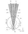
- FIG. 16 schematically shows the visual field range of the video display device 1C.
- the first projection light Lpj11, the second projection light Lpj12, and the third projection light Lpj13 from the first projector module Pj1 respectively cause, for example, the left eye of the observer in the horizontal direction.
- Three viewpoint images are formed in different areas (first projection area Ar11, second projection area Ar12, and third projection area Ar13) near 4L.
- the first projection light Lpj21, the second projection light Lpj22, and the third projection light Lpj23 from the second projector module Pj2 for example, in the horizontal direction, in the vicinity of the right eye 4R of the observer.
- Three viewpoint images are formed in different areas (first projection area Ar21, second projection area Ar22, and third projection area Ar23).
- the observer observes a stereoscopic image by the respective first projection lights Lpj11 and Lpj21 from the first and second projector modules Pj1 and Pj2.
- the observer observes a stereoscopic image by the respective second projection lights Lpj12 and Lpj22 from the first and second projector modules Pj1 and Pj2.
- the observer observes a stereoscopic image by the respective third projection lights Lpj13 and Lpj23 from the first and second projector modules Pj1 and Pj2.
- stereoscopic video is displayed by using only two viewpoint videos.
- the horizontal diffusion angles of the two projection lights forming the two-viewpoint viewpoint images are set to, for example, the diffusion angles corresponding to the vergence angles of both eyes at the optimum observation position.
- the viewpoint position detection unit 11 causes a detection error and a tracking delay.
- the viewpoint image may not be displayed at the correct viewpoint position. To compensate for this, it is necessary to set the diffusion angle wide within the range where crosstalk does not matter.
- the first and second projector modules Pj1 and Pj2 are respectively provided with, for example, a range of vergence angles of both eyes.
- the viewpoint positions are slightly moved in the horizontal direction.
- noise may be removed by filtering in the time direction in order to reduce detection noise of the viewpoint position in the viewpoint position detection unit 11.
- the configuration example in which the number of viewers is one has been described.
- projection is performed.
- the viewpoint position detection unit 11 detects the viewpoint positions of the plurality of observers.
- Each of the plurality of projection units is rotatable and movable.
- the projector module position control unit 12 rotationally moves each of the plurality of projection units to a position corresponding to the viewpoint positions of different observers detected by the viewpoint position detection unit 11.
- FIG. 17 schematically shows a main part of the video display device 1D-1 according to the first configuration example of the fifth embodiment as viewed from the top surface direction.
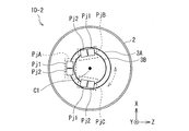
- FIG. 18 schematically shows a main part of the video display device 1D-2 according to the second configuration example of the fifth embodiment as viewed from the top surface direction.
- FIG. 19 schematically shows a main part of the video display device 1D-3 according to the third configuration example of the fifth embodiment as viewed from the top surface direction.
- the image display devices 1D-1, 1D-2, and 1D-3 according to the first to third configuration examples respectively include three projection units (first projector unit PjA, second projector unit) as a plurality of projection units. PjB and a third projector unit PjC).
- the configuration may be such that two or four or more projection units (projector units) are provided.
- the first to third projector units PjA, PjB and PjC respectively have a first projector module Pj1 and a second projector module Pj1 having substantially the same configuration as the image display device according to any one of the first to fourth embodiments.
- the projector module Pj2 is provided.
- the first to third projector units PjA, PjB, and PjC are arranged on the circumference of one rail 3, respectively. ing.
- the first to third projector units PjA, PjB, PjC are rotatable and movable independently of each other on the circumference of one rail 3.
- the video display device 1D-2 includes, as shown in FIG. 18, instead of one rail 3, two circular rails 3A and 3B having different diameters.
- the two rails 3A and 3B are arranged on the same plane.
- the respective central axes of the two rails 3A and 3B substantially coincide with the central axis C1 of the reflective cylindrical screen 2.
- the first to third projector units PjA, PjB, PjC are arranged on the circumference of one of the two rails 3A, 3B, respectively.
- the first projector unit PjA is arranged on the circumference of the rail 3A
- the second projector unit PjB and the third projector unit PjC are arranged on the circumference of the rail 3B.
- the video display device 1D-3 according to the third configuration example has the same diameter as that of the video display device 1D-2 according to the second configuration example, instead of one rail 3, as shown in FIG. It is provided with two circular rails 3A and 3B having different shapes.
- the two rails 3A and 3B are stacked on different planes (different positions in the Y direction in FIG. 19).
- the rail 3A is arranged in a plane including the paper surface of FIG. 19, and the rail 3B is arranged above or below the plane including the paper surface.
- Other configurations are similar to those of the video display device 1D-2 according to the second configuration example.
- the rails 3A and 3B correspond to a specific example of “rotational drive mechanism section” in the technology of the present disclosure.
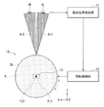
- FIG. 20 schematically shows a configuration example of the video display device 1E according to the sixth embodiment as viewed from the top surface direction.
- the video display device 1E according to the sixth embodiment is different from the video display device 1 according to the first embodiment in that it has a transmissive cylindrical screen 2A instead of the reflective cylindrical screen 2. There is.
- the transmissive cylindrical screen 2A corresponds to a specific but not limitative example of “diffusion member” in the technology of the present disclosure.
- FIG. 21 schematically shows a configuration example of the transmissive cylindrical screen 2A in the video display device 1E.
- FIG. 22 schematically shows an equivalent configuration example of the transmissive cylindrical screen 2A in the video display device 1E.
- the transmissive cylindrical screen 2A is a diffusing member having an anisotropic diffusing property in which the light diffusing property is different in the horizontal direction and the vertical direction.
- the transmission type cylindrical screen 2A has two lenticular lenses (first lenticular lens 41A and first lenticular lens 41A and an outer peripheral surface) having the same thickness as the focal lengths f1 and f2. It has a cylindrical surface having a lens action equivalent to the structure in which two lenticular lenses 42A) are arranged to face each other.
- the cylindrical surface of the transmissive cylindrical screen 2A acts as a condensing unit that condenses the first and second projection lights Lpj1 and Lpj2.
- the transmissive cylindrical screen 2A is composed of, for example, a transmissive holographic optical element (HOE). As shown in FIG. 21, the transmissive cylindrical screen 2A has, for example, an inner peripheral surface as a first HOE surface 41 and an outer peripheral surface as a second HOE surface 42.
- the first HOE surface 41 acts as the first lenticular lens 41A shown in FIG.
- the second HOE surface 42 acts as the second lenticular lens 42A shown in FIG.
- Optimum observation of the first and second projection lights Lpj1 and Lpj2 is achieved by adjusting the ratio of the focal lengths f1 and f2 of the first HOE surface 41 and the second HOE surface 42 of the transmissive cylindrical screen 2A.
- the light can be collected at the position.
- Light diffusion that results in relatively narrow diffusion in the horizontal direction and relatively wide diffusion in the vertical direction on either or both of the first HOE surface 41 and the second HOE surface 42 of the transmissive cylindrical screen 2A. Characteristic is added.
- the first and second projection lights Lpj1 and Lpj2 are condensed toward the observer's viewpoint position on the cylindrical surface, respectively, while being relatively diffused in the horizontal direction and vertically diffused. Diffuse so as to be relatively wide in the direction.
- the cylindrical surface of the transmissive cylindrical screen 2A corresponds to a specific example of “a light collecting unit” in the technology of the present disclosure.
- the reflective cylindrical screen 2 may be replaced with a transmissive cylindrical screen 2A.
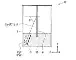
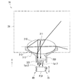
- FIG. 23 schematically shows a configuration example of the video display device 1F according to the seventh embodiment as viewed from the top surface direction.
- FIG. 24 schematically shows a configuration example of a lateral cross section of the video display device 1F according to the seventh embodiment.
- the video display device 1F according to the seventh embodiment is different from the video display device 1 according to the first embodiment in that a transparent cover 5 and a reflective flat screen 6 are used instead of the reflective cylindrical screen 2. It is equipped with it.
- the transparent cover 5 has a cylindrical shape, and is arranged at substantially the same position as the reflective cylindrical screen 2 in the video display device 1 according to the first embodiment.
- the transparent cover 5 does not substantially have a lens function or a light diffusing function, and may be omitted from the configuration.
- the reflective flat screen 6 is, for example, arranged near the center when viewed from the top surface direction.
- the reflective flat screen 6 includes a reflective flat surface having a lens action equivalent to that of a Fresnel lens.
- the reflective flat screen 6 is composed of, for example, a flat reflective holographic optical element (HOE), and the reflective flat surface having a lens function is an HOE surface.
- HOE holographic optical element
- the projection light is emitted from each of the first and second projector modules Pj1 and Pj2 toward the reflection plane of the reflection type flat screen 6.
- the HOE surface of the reflection type flat screen 6 is provided with a light diffusion characteristic of relatively narrow diffusion in the horizontal direction and relatively wide diffusion in the vertical direction.
- the first and second projection lights Lpj1 and Lpj2 from the first and second projector modules Pj1 and Pj2 are condensed toward the observer's viewpoint position on the reflection plane.
- the diffusion is relatively narrow in the horizontal direction and relatively wide in the vertical direction.
- the reflective flat screen 6 corresponds to a specific but not limitative example of “diffusing member” in the technology of the present disclosure.
- the reflective flat surface of the reflective flat screen 6 corresponds to a specific but not limitative example of “focusing unit” in the technology of the present disclosure.
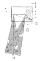
- FIG. 25 schematically shows an example of the relationship between the projection elevation angle ⁇ and the rotational movement directions of the first and second projector modules Pj1 and Pj2 in the video display device 1 according to the first embodiment.
- FIG. 26 schematically shows an example of the relationship between the projection elevation angle ⁇ and the rotational movement directions of the first and second projector modules Pj1 and Pj2 in the video display device 1F according to the seventh embodiment.
- the first and second projector modules Pj1 and Pj2 have a constant projection elevation angle ⁇ with respect to the cylindrical reflecting surface of the reflective cylindrical screen 2 as shown in FIG. It is preferable to rotate and move on such a plane.
- the first and second projector modules Pj1 and Pj2 have a projection elevation angle ⁇ with respect to the reflection plane of the reflection type flat screen 6 as shown in FIG. It is preferable to rotate and move on a plane that is constant.
- the first and second projector modules Pj1 and Pj2 are rotationally moved depending on whether the reflective cylindrical screen 2 is used or the reflective flat screen 6 is used.
- the plane to do is different.
- the reflective cylindrical screen 2 is rotationally moved on a plane (ZX plane) that is not inclined in the vertical direction (Y axis).
- the rail 3 is arranged in the ZX plane.
- the reflection type flat screen 6 When the reflection type flat screen 6 is used, as shown in FIG. 26, it is rotated and moved on a plane inclined with respect to the vertical direction (Y axis). In this case, the tilt angle is an angle corresponding to the projection elevation angle ⁇ .
- the rail 3 is arranged in an inclined plane.
- the elevation angle with respect to the reflection type flat screen 6 (in the YZ section of the incident light vector R in the YZ section). Angle) will be constant.
- the exit elevation angle (the angle of the reflected light vector S in the YZ cross section) can also be made constant.
- FIG. 30 schematically shows a configuration example of the video display device 1G according to the eighth embodiment as viewed from the top surface direction.
- FIG. 31 schematically shows a configuration example of a lateral cross section of the video display device 1G according to the eighth embodiment.
- the video display device 1G according to the eighth embodiment is different from the video display device 1 according to the first embodiment in that the rail 3 is replaced by a Fresnel lens rotating body 7 and a rotary stage 8. Further, the image display device 1G is different from the image display device 1 according to the first embodiment in that the projector module position control unit 12 is replaced with a rotation control unit 14 that controls the rotation angle of the Fresnel lens rotating body 7. I have it.
- the first projector module Pj1 and the second projector module Pj2 and the Fresnel lens rotator 7 correspond to a specific example of a “projection unit” in the technique of the present disclosure.
- the rotation control unit 14 corresponds to a specific but not limitative example of “control unit” in the technology of the present disclosure.
- the Fresnel lens rotating body 7 is arranged on a rotating stage 8 and is rotatable.
- the rotation center axis of the Fresnel lens rotator 7 substantially coincides with the center axis C1 of the reflective cylindrical screen 2.
- the first and second projection lights Lpj1 and Lpj2 emitted from the first and second projector modules Pj1 and Pj2 respectively pass through the Fresnel lens rotating body 7 and then are observed by the cylindrical reflecting surface of the reflective cylindrical screen 2. It is focused toward the viewpoint of the person.
- the Fresnel lens rotator 7 is rotated instead of the first and second projector modules Pj1 and Pj2 being rotationally moved, so that the focusing positions of the first and second projection lights Lpj1 and Lpj2. Is approximately matched with the viewpoint position of the observer.
- the rotation control unit 14 controls the rotation stage 8 so that the rotation angle of the Fresnel lens rotator 7 becomes an angle according to the viewpoint position detected by the viewpoint position detection unit 11.
- FIG. 32 schematically shows a configuration example of the video display device 1H according to the ninth embodiment as viewed from the top surface direction.
- FIG. 33 schematically shows a configuration example of a lateral cross section of the video display device 1H according to the ninth embodiment.
- the image display device 1H according to the ninth embodiment is different from the image display device 1E (FIG. 20) according to the sixth embodiment in that a reflective decentering Fresnel lens rotating body 9 is used instead of the rail 3. I have it.
- the image display device 1H is different from the image display device 1E according to the sixth embodiment in that the projector module position control unit 12 is replaced by a rotation controlling the rotation angle of the reflective eccentric Fresnel lens rotating body 9.
- the controller 15 is provided.
- the first projector module Pj1 and the second projector module Pj2 and the reflective decentered Fresnel lens rotating body 9 correspond to a specific example of “projection unit” in the technology of the present disclosure. ..
- the rotation control unit 15 corresponds to a specific but not limitative example of “control unit” in the technology of the present disclosure.
- the reflective eccentric Fresnel lens rotator 9 is arranged on the upper surface of the transmissive cylindrical screen 2A, which is the top surface, and is rotatable.
- the rotation center axis of the reflection type eccentric Fresnel lens rotating body 9 is substantially coincident with the center axis C1 of the transmission type cylindrical screen 2A.
- the first and second projector modules Pj1 and Pj2 are arranged at a substantially central position when viewed from the top surface direction.
- the first and second projection lights Lpj1 and Lpj2 emitted from the first and second projector modules Pj1 and Pj2 are reflected by the reflective decentered Fresnel lens rotating body 9, respectively, and then the cylinder of the transmissive cylindrical screen 2A.
- the light is focused by the surface toward the observer's viewpoint position.
- the reflective decentered Fresnel lens rotating body 9 rotates instead of rotating the first and second projector modules Pj1 and Pj2, so that the first and second projection lights Lpj1 and Lpj2.
- the light collecting position of (3) is made to substantially coincide with the viewpoint position of the observer.
- the rotation control unit 15 controls the rotation angle of the reflective eccentric Fresnel lens rotator 9 so that the rotation position becomes an angle according to the viewpoint position detected by the viewpoint position detection unit 11.
- FIG. 34 schematically shows a configuration example of the video display device 1I according to the tenth embodiment as viewed from the top surface direction.
- FIG. 35 schematically shows a configuration example of a lateral cross section of the video display device 1I according to the tenth embodiment.
- the image display device 1I according to the tenth embodiment is different from the image display device 1E (FIG. 20) according to the sixth embodiment in that the transmission type decentered Fresnel lens rotating body 9A is used instead of the rail 3. , And a reflection mirror 22. Further, the image display device 1I is different from the image display device 1E according to the sixth embodiment in that the projector module position control unit 12 is replaced by a rotation for controlling the rotation angle of the transmission type eccentric Fresnel lens rotating body 9A.
- the controller 15 is provided.
- the first projector module Pj1 and the second projector module Pj2, the transmissive eccentric Fresnel lens rotating body 9A, and the reflection mirror 22 are one specific example of the “projection unit” in the technique of the present disclosure.
- the rotation control unit 15 corresponds to a specific but not limitative example of “control unit” in the technology of the present disclosure.
- the transmissive eccentric Fresnel lens rotating body 9A is arranged at the bottom and bottom of the transmissive cylindrical screen 2A, and is rotatable.
- the rotation center axis of the transmission type eccentric Fresnel lens rotating body 9A is substantially coincident with the center axis C1 of the transmission type cylindrical screen 2A.
- the reflection mirror 22 is arranged on the optical path between the transmission type eccentric Fresnel lens rotating body 9A and the first and second projector modules Pj1 and Pj2.
- the first and second projection lights Lpj1 and Lpj2 emitted from the first and second projector modules Pj1 and Pj2 are reflected by the reflection mirror 22 and then transmitted through the transmission type decentered Fresnel lens rotating body 9A. ..
- the first and second projection lights Lpj1 and Lpj2 that have passed through the transmissive eccentric Fresnel lens rotating body 9A are focused by the cylindrical surface of the transmissive cylindrical screen 2A toward the observer's viewpoint position.
- the transmission type eccentric Fresnel lens rotator 9A rotates instead of the first and second projector modules Pj1 and Pj2 rotatively moving, whereby the first and second projection lights Lpj1 and Lpj2.
- the light collecting position of (3) is made to substantially coincide with the viewpoint position of the observer.
- the rotation control unit 15 controls the rotation angle of the transmissive eccentric Fresnel lens rotator 9A so that it becomes an angle corresponding to the viewpoint position detected by the viewpoint position detection unit 11.
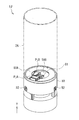
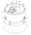
- FIG. 36 shows an outline of the external appearance of the video display device 1J according to the eleventh embodiment.
- FIG. 37 schematically shows a main part of a configuration example of the video display device 1J.
- FIG. 38 schematically shows a configuration example of a lateral cross section of the video display device 1J.
- the video display device 1J according to the eleventh embodiment includes a transmissive cylindrical screen 2A similar to that of the video display device 1E (FIG. 20) according to the sixth embodiment. Further, the image display device 1J is capable of performing stereoscopic image display for a plurality of observers by including a plurality of projection units, as in the image display device according to the fifth embodiment. There is.
- the viewpoint position detection unit 11 detects the viewpoint positions of the plurality of observers, similarly to the video display device according to the fifth embodiment.
- Each of the plurality of projection units is rotatable and movable.
- the projector module position control unit 12 rotationally moves each of the plurality of projection units to a position corresponding to the viewpoint positions of different observers detected by the viewpoint position detection unit 11.
- the image display device 1J includes two projection units (a first projector unit PjA and a second projector unit PjB) as a plurality of projection units.
- the image display device 1J includes two turntables 50A and 50B corresponding to the two rails 3A and 3B in the image display device 1D-3 (FIG. 19) according to the third configuration example of the fifth embodiment.
- the first projector unit PjA is arranged on the turntable 50A.
- the second projector unit PjB is arranged on the turntable 50B. Note that, in FIG. 36, the projection unit is illustrated as being visible from the outside for the sake of explanation, but a light shielding plate or the like may be arranged so that the projection unit is not visible from the outside.
- the first and second projector units PjA and PjB respectively include, for example, first and second projector modules Pj1 and Pj2 having substantially the same configuration as the video display device 1 and the like according to the first embodiment. There is.
- the turntables 50A and 50B have different diameters and are stacked on different planes (positions different in the Y direction in FIG. 36).
- the turntable 50A has a larger diameter than the turntable 50B and is arranged on the upper side.
- the turntables 50A and 50B can be rotated independently of each other.
- the image display device 1J by rotating each of the turntables 50A and 50B, it is possible to rotate and move each of the first and second projector units PjA and PjB independently of each other.
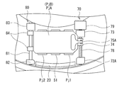
- the first and second projector units PjA and PjB have linear drive mechanism units 70 and 80, respectively, and on the turntables 50A and 50B, directions orthogonal to the rotational movement direction. It is possible to move linearly in the (observation distance direction). As a result, in the image display device 1J, the emission positions of the respective projection lights from the first and second projector units PjA and PjB can be adjusted. As a result, it is possible to adjust the focus positions (focus positions) of the respective projection lights from the first and second projector units PjA and PjB.
- the projector module position control unit 12 sets the rotational positions of the first and second projector units PjA and PjB to positions corresponding to the horizontal viewpoint position of the observer detected by the viewpoint position detection unit 11. Then, the turntables 50A and 50B are rotationally moved. Further, the projector module position control unit 12 determines that the positions of the first and second projector units PjA and PjB in the observation distance direction are the viewpoint positions in the observation distance direction of the observer detected by the viewpoint position detection unit 11.
- the linear drive mechanism units 70 and 80 linearly move the first and second projector units PjA and PjB so as to be in the corresponding positions.
- the viewpoint position detection unit 11 includes a fine adjustment camera module 51 and a coarse adjustment camera module 52.
- the fine adjustment camera module 51 and the coarse adjustment camera module 52 each detect the viewpoint position of the observer, but have different detection ranges, as will be described later.
- each of the turntables 50A and 50B corresponds to a specific example of “rotational drive mechanism section” in the technology of the present disclosure.
- the fine adjustment camera module 51 corresponds to a specific but not limitative example of “first detection unit” in the technology of the present disclosure.
- the coarse adjustment camera module 52 corresponds to a specific but not limitative example of “second detector” in the technology of the present disclosure.
- the fine adjustment camera module 51 is incorporated in each of the first and second projector units PjA and PjB together with the first and second projector units PjA and PjB.
- FIG. 37 shows an example in which the fine adjustment camera module 51 is arranged between the first and second projector units PjA and PjB, the first and second projector units PjA and PjB and The arrangement of the adjustment camera module 51 is not limited to the example shown in FIG.
- a plurality of rough adjustment camera modules 52 are provided on the outer periphery of the housing 10.
- the coarse adjustment camera module 52 performs, for example, coarse adjustment of how many people are present around the image display device 1J and the fine adjustment camera module 51 determines to which person the viewpoint position should be detected.
- each of the turntables 50A and 50B has a center of rotation which is a hollow portion 61 in which the wiring 62 can be arranged.
- the wiring 62 includes, for example, an electric wiring and an optical communication wiring connected to each of the first and second projector units PjA and PjB.
- the electric power of the first and second projector units PjA and PjB installed on the turntables 50A and 50B is reduced.
- the place for passing the wiring 62 such as the wiring or the optical communication wiring is configured to pass through the gap between the outer peripheral case and the case. In that case, it goes without saying that the wiring 62 is twisted with the rotation, but the distance of friction on the circumference becomes long, and the possibility of wire breakage increases. Also, the twisting limits the rotation angle very much.
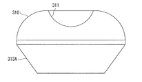
- each of the turntables 50A and 50B is a hollow drive mechanism that does not have a rotation axis near its center, the rotational twist can be minimized, so that the turnable angle rotates greatly over several turns. It becomes possible. Since the load of rotation can be reduced, high-speed rotation is possible and durability is also improved. Further, as in the image display device 1K (FIGS. 59 to 65) according to the twelfth embodiment described later, it is possible to dispose the projection portion in the hollow portion, and the degree of freedom in optical design is increased. For example, a structure using an all-around lens 310 as in a video display device 1K (FIGS. 59 to 65) according to a twelfth embodiment described later is also possible.
- FIG. 39 schematically shows a first example of a projection state by the first projector unit PjA in the video display device 1J.
- FIG. 40 schematically shows a first example of the projection state by the second projector unit PjB in the video display device 1J.
- the projection light may be directly projected from the first and second projector units PjA and PjB toward the cylindrical surface of the transmissive cylindrical screen 2A.
- the observer can observe a stereoscopic image in the first and second projection areas Ar1 and Ar2.
- the fine adjustment camera module 51 can detect the viewpoint position of the observer within a range of a shooting area Ar ⁇ (shooting angle of view) that is substantially the same as the first and second projection areas Ar1 and Ar2.
- a shape marker for detecting the viewpoint position by the fine adjustment camera module 51 is provided on the opposite side (opposing side) of the first and second projector units PjA and PjB.
- the sights 91A and 91B may be provided.
- FIG. 41 schematically shows a second example of the projection state by the first projector unit PjA in the video display device 1J.
- FIG. 42 schematically shows a second example of the projection state by the second projector unit PjB in the video display device 1J.
- the reflection mirror 23 may be provided on the optical path of the projection light from the first and second projector units PjA and PjB in each of the turntables 50A and 50B. Then, the projection light from the first and second projector units PjA and PjB may be reflected by the reflection mirror 23 and then projected toward the cylindrical surface of the transmissive cylindrical screen 2A. Further, the relay lens 24 may be arranged on the optical path between the first and second projector units PjA and PjB and the reflection mirror 23.
- Example of configuration of rotation drive mechanism section 43 and 44 schematically show a main part of a configuration example of the video display device 1J.
- FIG. 45 schematically shows an exploded view of a main part of a configuration example of the video display device 1J.
- FIG. 46 schematically shows a main part of a configuration example of the video display device 1J. 43 to 46, when the projection light from the first and second projector units PjA and PjB is reflected by the reflection mirror 23 and projected as in the configuration example shown in FIGS. 41 and 42. A configuration example of is shown.
- the rotation drive mechanism section is composed of, for example, a ring type ultrasonic motor.
- ring type ultrasonic motors having different sizes are arranged under the turntables 50A and 50B, respectively, and drive the turntables 50A and 50B in the rotational direction. It is possible.
- Each of the turntables 50A and 50B can be rotationally driven without interfering with each of the first and second projector units PjA and PjB.
- the wires 62 such as electric wires and optical communication wires of the first and second projector units PjA and PjB are connected from the hollow portion 61 at the center to a system circuit unit and a power supply unit (not shown) below.
- FIG. 47 and 48 show modified examples of the rotation drive mechanism section in the image display device 1J.
- FIG. 47 schematically shows a planar configuration example of the rotation drive mechanism section according to the modification.
- FIG. 48 schematically shows an external configuration example of a rotation drive mechanism section according to a modification.
- the rotation drive mechanism unit may be configured to include a gear drive system motor arranged on the outer periphery. As shown in FIGS. 47 and 48, a turntable side gear 53 and a drive side gear 54 that meshes with the turntable side gear 53 are provided on the outer peripheral portions of the turntables 50A and 50B, respectively. Good.
- the drive gear 54 may be driven by the DC motor 55.
- the turntable side gear 53 may be driven by the DC motor 55 via the drive side gear 54.
- the ring-type ultrasonic motor has a short start-up time and reversal time, and it is possible to quickly follow the observer's fine and quick behavior.
- the gear drive type motor arranged on the outer circumference has a long start-up time and a reversal time, it is possible to follow a movement such that the observer keeps moving fast in a certain direction at a high speed. It suffices to select a motor that corresponds to the expected movement of the observer.
- the structure becomes complicated, by using both of these two motors, it is possible to follow a fine and quick behavior as well as a movement that continues to move fast in a certain direction.
- FIG. 49 schematically shows the arrangement of the fine adjustment camera module 51 and the coarse adjustment camera module 52 in the image display device 1J.
- the fine adjustment camera module 51 incorporated in each of the first and second projector units PjA and PjB can independently detect the viewpoint position in each of the first and second projector units PjA and PjB. Is.
- the viewpoint position detection method since the respective viewpoint position detection methods in the first and second projector units PjA and PjB are the same, the viewpoint position detection method will be described without distinction between the first and second projector units PjA and PjB. To do.
- the projection light (first and second projection light Lpj1, Lpj2) from the first and second projector modules Pj1 and Pj2 is actually projected. It is at least a part of the range (first and second projection areas Ar1, Ar2).
- the fine adjustment camera module 51 detects, for example, the viewpoint position in the vicinity of the area where the projection light is actually projected.
- a plurality of coarse adjustment camera modules 52 are provided on the outer periphery of the casing 10 of the video display device 1J.
- the detection range of the viewpoint position by the plurality of coarse adjustment camera modules 52 includes, for example, the entire range in which projection light can be projected.
- the plurality of coarse adjustment camera modules 52 detect the viewpoint position in, for example, substantially the entire circumference of the transmissive cylindrical screen 2A and the circumference of 360 °.
- the fine adjustment camera module 51 is arranged on the turntables 50A and 50B together with the first and second projector modules Pj1 and Pj2 that project an image. As a result, the fine adjustment camera module 51 rotates and moves at the same time as the image, so that the detection accuracy of the viewpoint position and the position adjustment accuracy of the first and second projector modules Pj1 and Pj2 that match the viewpoint position can be improved. it can.
- the rough adjustment camera module 52 can grasp the approximate viewpoint position of the observer. Therefore, after roughly tracking to the viewpoint position, the coarse adjustment camera module 52 can be used within the narrow range by the fine adjustment camera module 51. It is sufficient to grasp the viewpoint position in detail. Thereby, the viewing angle of the detection lens system in the fine adjustment camera module 51 can be narrowed. As an effect, the resolution per pixel can be finely controlled in order to image only the range near the face or eyes of the observer.
- FIG. 50 schematically shows a first example of a viewpoint position detection method in the video display device 1J.
- the first and second projector modules Pj1 and Pj2 emit the first and second projection lights Lpj1 and Lpj2, respectively, including the first and second detection markers Ir1 and Ir2.
- the first and second detection markers Ir1 and Ir2 are drawn in the vertical direction as shown in FIG.
- the wavelengths used as the first and second detection markers Ir1 and Ir2 are preferably near infrared, but are not limited to near infrared.
- the fine adjustment camera module 51 detects the projection positions of the first and second detection markers Ir1 and Ir2 and the positions of both eyes of the observer.
- the projector module position controller 12 calculates the difference between the projected position of the first and second detection markers Ir1 and Ir2 and the position of the observer's eye.
- FIG. 50A an example in which the projection positions of the first and second detection markers Ir1 and Ir2 are displaced to the right with respect to both eyes of the observer when viewed from the side of the fine adjustment camera module 51.
- FIG. 50B shows an example in which the projection positions of the first and second detection markers Ir1 and Ir2 are coincident with both eyes of the observer.
- FIG. 50C an example in which the projection positions of the first and second detection markers Ir1 and Ir2 are shifted to the left with respect to both eyes of the observer when viewed from the side of the fine adjustment camera module 51. Show.
- the projector module position control unit 12 may, for example, based on the difference between the projected positions of the first and second detection markers Ir1 and Ir2 and the position of the observer's eyes, for example, the first and second projector units PjA and PjB.
- the turntables 50A and 50B are rotationally moved so that the respective rotational positions of the turntables become positions according to the detected viewpoint position of the observer in the horizontal direction.
- the first and second projector modules Pj1 and Pj2 When performing color display, the first and second projector modules Pj1 and Pj2 have light sources of three colors of R (red), G (green), and B (blue), for example.
- a near-infrared light source for example, is added to the three-color light sources to detect a viewpoint position in a vertical direction in a part of the viewpoint image. It emits including the first and second detection markers Ir1 and Ir2.
- the fine adjustment camera module 51 is configured to include a detection element having sensitivity to visible light and near-infrared light to detect the first and second detection markers Ir1 and Ir2.
- the fine adjustment camera module 51 also has visible light sensitivity, it can simultaneously detect the position of the face or eye of the observer and the positions of the first and second detection markers Ir1 and Ir2 in the near infrared.
- the projector module position controller 12 rotationally moves the turntables 50A and 50B, for example, so that the positions of the first and second detection markers Ir1 and Ir2 and the positions of the left eye 4L and the right eye 4R match.
- the positions of the first and second projector units PjA and PjB are made to follow the observer's viewpoint position. This enables extremely accurate tracking.
- the fine adjustment camera module 51 need not be integrated with the first and second projector units PjA and PjB as long as it is on the turntables 50A and 50B.
- FIG. 51 schematically shows a second example of the viewpoint position detection method in the video display device 1J.
- the image display device 1J may further include a shape marker that rotates together with the projection unit.
- the fine adjustment camera module 51 may be able to detect the position of the shape marker with respect to the observer and the position of the observer's eyes.
- the projector module position control unit 12 may rotate the projection unit based on the difference between the position of the shape marker with respect to the observer and the position of the observer's eyes.
- sighting devices 91A and 91B serving as shape markers may be provided on the opposite side (opposing side) of the first and second projector units PjA and PjB.
- the fine adjustment camera module 51 detects the aiming reference position 91C of the aiming devices 91A and 91B and the positions of both eyes of the observer.
- the projector module position controller 12 calculates the difference between the aiming reference position 91C and the position of the observer's eyes.
- FIG. 51A shows an example in which the sighting reference position 91C is displaced to the right with respect to both eyes of the observer when viewed from the side of the fine adjustment camera module 51.
- FIG. 51 (B) shows an example in which the sighting reference position 91C and the eyes of the observer match.
- FIG. 51C shows an example in which the sighting reference position 91C is displaced to the left with respect to both eyes of the observer when viewed from the side of the fine adjustment camera module 51.
- a detection marker such as a convex portion is arranged as a structure at a position facing the fine adjustment camera module 51 on the turntables 50A and 50B, and a position (aiming reference position 91C) extended above the shape marker is provided. Tracking control that matches the position of the observer's face and eyes is performed.
- an infrared light source or the like for generating a detection marker which is used in the first detection method, is not required, and the structure is inexpensive.
- linear drive mechanism units 70 and 80 are provided on both sides of the first and second projector units PjA and PjB. This allows the first and second projector units PjA and PjB to move linearly in the direction (observation distance direction) orthogonal to the rotational movement direction. As a result, it is possible to adjust the focus positions (focus positions) of the respective projection lights from the first and second projector units PjA and PjB.
- the linear drive mechanism units 70 and 80 may include a direct-acting ultrasonic motor or a stepping motor.
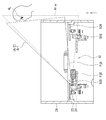
- Linear drive mechanism using ultrasonic motor 52 and 53 schematically show a first example of a linear drive mechanism for the first and second projector units PjA and PjB in the image display device 1J.
- FIG. 52 shows a planar configuration example.
- FIG. 53 shows an external configuration example.
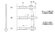
- the linear drive mechanism unit 70 has a configuration including a shaft 71, a turntable side bearing 72, a turntable side bearing 73, a bearing 74, a pressurizing spring 75, a weight 76, and a piezoelectric element 77. May be.
- the linear drive mechanism unit 80 may have a configuration including a shaft 81, a turntable side bearing 82, a turntable side bearing 83, and a bearing 84.
- the first and second projector units PjA and PjB are linearly movable along the shaft 71 of the linear drive mechanism unit 70 and the shaft 81 of the linear drive mechanism unit 80, respectively.
- the linear drive mechanism unit 70 includes an ultrasonic motor.
- the weight 76 is a weight having a large specific gravity for receiving the vibration of the piezo-piezoelectric element 77 serving as a vibration source.
- a laminated piezoelectric element 77 is bonded to the tip of the weight 76.
- At the tip of the piezoelectric element 77 there is a shaft 71 for transmitting a driving force with a sawtooth vibration waveform, and a bearing 74 formed on each of the first and second projector units PjA and PjB to move the shaft 71 is provided. Take it.
- a pressurizing spring 75 is added to the bearing 74, which causes strong friction between the shaft 71 and the bearing 74.
- FIG. 54 schematically shows an example of the driving principle of the ultrasonic motor.
- FIG. 55 schematically shows the relationship between the drive voltage (drive waveform) of the ultrasonic motor and the displacement of the movable part.
- the positions of (A), (B), and (C) of the drive waveforms of FIG. 55 correspond to the states of (A), (B), and (C) of FIG. 54.
- the first and second projector units PjA and PjB are held at their linear positions ((A) in FIG. 54).
- the saw-tooth drive is performed as shown in FIG. 55, the first and second projector units PjA and PjB are arranged to slide in the direction in which the waveform slopes and to follow in the direction in which the waveform slopes. Respectively move in one direction ((B) and (C) in FIG. 54).
- the direct-drive ultrasonic motor has a short starting time and reversing time, and can quickly follow the observer's fine and quick behavior.
- FIG. 56 schematically shows a second example of the linear drive mechanism of the first and second projector units PjA and PjB in the image display device 1J.
- FIG. 56 shows a planar configuration example.
- the linear drive mechanism unit 70 has a configuration including a turntable side tip pivot bearing 72A, a turntable side bearing 73, a bearing 74, a toothed pressurizing spring 75A, a lead screw 78, and a stepping motor 79. May be.
- the linear drive mechanism unit 80 may have a configuration including a shaft 81, a turntable side bearing 82, a turntable side bearing 83, and a bearing 84.
- the first and second projector units PjA and PjB are linearly movable along the shaft 71 of the linear drive mechanism unit 70 and the lead screw 78 of the linear drive mechanism unit 80, respectively.
- the teeth of the lead screw 78 mesh with the teeth of the toothed pressurizing spring 75A. Accordingly, by rotating the lead screw 78 by the stepping motor 79, the first and second projector units PjA and PjB joined to the toothed pressurizing spring 75A can be linearly moved.
- 57 and 58 schematically show an example of the driving principle of the stepping motor 79.
- the stepping motor 79 includes, for example, a circular stator in which a plurality of coils L1, L2, L3, and L4 are wound, and a rotor including a magnet.
- the rotor is rotatably arranged in the center of the inner peripheral side of the stator.
- the rotation angle of the rotor is determined by which of the coils L1, L2, L3, L4 the current is applied to.
- FIG. 57 shows a state in which a current is applied to the coil L1.
- the coil L1 becomes an electromagnet (for example, S pole), and one end (for example, N pole) of the central rotor is attracted by the magnetic force of the coil L1 to rotate, and stops at a position facing the coil L1.
- FIG. 58 shows a state in which a current is passed through the coil L2.
- the coil L2 serves as an electromagnet (for example, S pole), and one end (for example, N pole) of the central rotor is attracted by the magnetic force of the coil L2 to rotate, and stops at a position facing the coil L2.
- FIGS. 57 and 58 simply show an example in which the step angle is 90 °, the step angle can be reduced by increasing the number of magnetic poles of the rotor and the stator.
- a rack and pinion type DC motor may be used as the linear drive mechanism.
- the start-up time and the reversal time become long, but it becomes possible to follow the movement that the observer keeps moving fast in a certain direction at a high speed.
- a linear drive mechanism using a stepping motor has an intermediate performance of two characteristics, that is, a linear drive mechanism using a rack and pinion type DC motor and a linear drive mechanism using an ultrasonic motor. It suffices to select a motor that corresponds to the expected movement of the observer. Further, although the structure becomes complicated, by using two different methods in combination, it is possible to follow a fine and quick behavior as well as a movement that continues to move fast in a certain direction.
- FIG. 59 shows an outline of the appearance of the video display device 1K according to the twelfth embodiment.
- FIG. 60 schematically shows a main part of a configuration example of the video display device 1K.
- FIG. 61 schematically shows a main part of a configuration example of a lateral cross section of the image display device 1K.
- FIG. 62 schematically shows a first example of a projection state by the video display device 1K.
- FIG. 63 schematically shows a second example of the projection state by the video display device 1K.
- the video display device 1K according to the twelfth embodiment includes a transmissive cylindrical screen 2A, like the video display device 1J according to the eleventh embodiment. Further, the image display device 1K includes, as a projection unit, the first projector unit PjA having the same configuration as the image display device 1J according to the eleventh embodiment.
- the image display device 1K includes an all-around lens 310 disposed below the transmissive cylindrical screen 2A.
- the upper part of the omnidirectional lens 310 is a reflecting surface 311.
- the image display device 1K also includes a reflecting portion 313 arranged below the omnidirectional lens 310.
- the central portion of the upper portion of the housing 10 and the central portion of the reflecting portion 313 are hollow portions 320.
- the inner surface of the reflecting portion 313 is a reflecting surface 312.
- the first projector unit PjA is arranged so as to emit the first and second projection lights Lpj1 and Lpj2 toward the reflecting surface 311 of the omnidirectional lens 310.
- a relay lens 321 may be arranged on the optical paths of the first and second projection lights Lpj1 and Lpj2.
- the first projector unit PjA is arranged in the hollow portion 320 so as to be rotatable around the entire circumference by a rotary drive mechanism such as a ring type ultrasonic motor. Further, the first projector unit PjA includes a linear drive mechanism having the same configuration as the image display device 1J according to the eleventh embodiment, and moves linearly in the vertical direction (Y direction in FIGS. 59 to 63). It is possible.
- the first and second projection lights Lpj1 and Lpj2 from the first projector unit PjA are reflected by the reflecting surface 311 above the omnidirectional lens 310. After being reflected, the light is further reflected by the reflecting surface 312 of the reflecting portion 313 arranged below the omnidirectional lens 310. The first and second projection lights Lpj1 and Lpj2 reflected by the reflecting surface 312 are emitted toward the cylindrical surface of the transmissive cylindrical screen 2A via the omnidirectional lens 310.
- a projection image 330 formed by the first and second projection lights Lpj1 and Lpj2 is formed on the reflecting surface 312 over the entire circumference.
- the projected image 330 formed on the reflecting surface 312 is observed by an observer via the all-round lens 310 and the transmissive cylindrical screen 2A. Thereby, the observer can observe the projection image 330 over the entire circumference of the transmissive cylindrical screen 2A.
- 62 and 63 schematically show the projection state by the image display device 1K when the viewers are at different positions.
- FIG. 64 schematically shows a first modification example of the video display device according to the twelfth embodiment.
- FIG. 65 schematically shows a second modification of the video display device according to the twelfth embodiment.
- the external shapes of the omnidirectional lens 310 and the reflection section 313 are not limited to the shapes shown in FIGS. 59 to 63. Further, the omnidirectional lens 310 and the reflecting portion 313 may be configured by separate members. For example, as shown in FIG. 64, the configuration may be such that the reflecting portion 313 is provided with an all-around lens 310A having a different outer diameter. Further, as shown in FIG. 65, a configuration may be adopted in which the reflecting surface 312 has a reflecting portion 313A having a linear cross section.
- the all-round lens 310 is not limited to the configuration in which the entire interior is filled with the glass material or the transparent resin material, and may have a configuration having a hollow portion.
- the present technology can also take the following configurations.
- the present technology having the following configuration it is possible to perform multi-view image display with high display quality in a wide range without increasing the size of the configuration.
- the projection unit is capable of adjusting a focus position of the projection light, The image according to (1) or (2), wherein the control unit controls the projection unit so that a condensing position of the projection light is a position corresponding to the viewpoint position detected by the detection unit.
- Display device The image display device according to any one of (1) to (3), wherein the diffusion member diffuses the projection light so as to have a diffusion distribution close to a rectangle in the horizontal direction.
- the projection unit emits projection light forming three or more viewpoint images.
- a plurality of the projection units are provided, and the detection unit is capable of detecting respective viewpoint positions of a plurality of observers, At least a part of each of the plurality of projection units is rotatably movable, Any one of the above (1) to (5), wherein the control unit rotationally moves at least a part of each of the plurality of projection units to a position according to the viewpoint positions of different observers detected by the detection unit.
- the video display device according to one.
- the light condensing unit includes a reflective holographic optical element formed on a cylindrical surface.
- the condensing unit has a cylindrical surface on each of which both surfaces have a lens action equivalent to a structure in which two lenticular lenses having the same thickness as each focal length are arranged to face each other, (1) to (6)
- the video display device according to.
- the light condensing unit includes a flat surface having a lens action equivalent to that of a Fresnel lens.
- the projection unit includes a Fresnel lens that is rotatably movable.
- the projection unit includes an eccentric Fresnel lens that is rotatably movable.
- the rotation center is a hollow in which wiring can be arranged, and a rotation drive mechanism unit that rotates and moves the projection unit,
- Each of the plurality of projection units is arranged on different planes or on different circumferences so that at least a part of them can be rotated independently of each other.
- the control unit rotates at least a part of each of the plurality of projection units independently of each other to a position corresponding to the viewpoint positions of different observers detected by the detection unit.
- the image display device (15) The image display device according to (12) or (13), wherein the rotation drive mechanism section includes a ring-type ultrasonic motor or a gear drive system motor arranged on the outer periphery.
- the projection unit includes a direct-acting ultrasonic motor or a stepping motor, and the light-condensing position of the projection light can be adjusted by linearly moving by the direct-acting ultrasonic motor or the stepping motor.
- the video display device according to (3) above.
- the detection unit includes first and second detection units having different detection ranges from each other.
- the detection range of the first detection unit is at least a part of the range in which the projection light is actually projected,
- the image display device according to (17), wherein the detection range of the second detection unit includes the entire range in which the projection light can be projected.
- the projection unit emits projection light including a detection marker,
- the first detection unit is capable of detecting the projection position of the detection marker and the position of the eye of the observer,
- the image according to (17) or (18), wherein the control unit rotationally moves at least a part of the projection unit based on a difference between the projection position of the detection marker and the position of the eye of the observer. Display device.
- the first detection unit is capable of detecting the position of the shape marker with respect to the observer and the position of the eye of the observer
- the control unit rotationally moves at least a part of the projection unit based on a difference between a position of the shape marker with respect to the observer and a position of an eye of the observer.
Landscapes
- Engineering & Computer Science (AREA)
- Multimedia (AREA)
- Signal Processing (AREA)
- Physics & Mathematics (AREA)
- General Physics & Mathematics (AREA)
- Testing, Inspecting, Measuring Of Stereoscopic Televisions And Televisions (AREA)
- Projection Apparatus (AREA)
- Devices For Indicating Variable Information By Combining Individual Elements (AREA)
- Details Of Cameras Including Film Mechanisms (AREA)
- Transforming Electric Information Into Light Information (AREA)
Priority Applications (3)
| Application Number | Priority Date | Filing Date | Title |
|---|---|---|---|
| JP2020553738A JP7439764B2 (ja) | 2018-10-31 | 2019-10-11 | 映像表示装置 |
| CN201980070035.3A CN112889276B (zh) | 2018-10-31 | 2019-10-11 | 图像显示装置 |
| DE112019005430.9T DE112019005430T5 (de) | 2018-10-31 | 2019-10-11 | Bildanzeigevorrichtung |
Applications Claiming Priority (2)
| Application Number | Priority Date | Filing Date | Title |
|---|---|---|---|
| JP2018205353 | 2018-10-31 | ||
| JP2018-205353 | 2018-10-31 |
Publications (1)
| Publication Number | Publication Date |
|---|---|
| WO2020090422A1 true WO2020090422A1 (ja) | 2020-05-07 |
Family
ID=70464121
Family Applications (1)
| Application Number | Title | Priority Date | Filing Date |
|---|---|---|---|
| PCT/JP2019/040210 Ceased WO2020090422A1 (ja) | 2018-10-31 | 2019-10-11 | 映像表示装置 |
Country Status (4)
| Country | Link |
|---|---|
| JP (1) | JP7439764B2 (https=) |
| CN (1) | CN112889276B (https=) |
| DE (1) | DE112019005430T5 (https=) |
| WO (1) | WO2020090422A1 (https=) |
Cited By (1)
| Publication number | Priority date | Publication date | Assignee | Title |
|---|---|---|---|---|
| EP4535064A4 (en) * | 2022-05-30 | 2025-07-30 | Sony Group Corp | IMAGE DISPLAY DEVICE |
Citations (9)
| Publication number | Priority date | Publication date | Assignee | Title |
|---|---|---|---|---|
| JPH01259348A (ja) * | 1988-04-11 | 1989-10-17 | Nippon Telegr & Teleph Corp <Ntt> | 3次元画像表示装置 |
| JPH05241099A (ja) * | 1992-03-02 | 1993-09-21 | A T R Tsushin Syst Kenkyusho:Kk | 観察者追従型表示装置 |
| JP2003207743A (ja) * | 2002-01-16 | 2003-07-25 | Olympus Optical Co Ltd | 立体観察装置 |
| JP2007047366A (ja) * | 2005-08-09 | 2007-02-22 | Seiko Epson Corp | プロジェクタ |
| WO2013005795A1 (ja) * | 2011-07-05 | 2013-01-10 | 国立大学法人東京農工大学 | 立体表示装置 |
| WO2013054634A1 (ja) * | 2011-10-14 | 2013-04-18 | 国立大学法人豊橋技術科学大学 | 立体画像投影装置、立体画像投影方法、及び立体画像投影システム |
| JP2014522591A (ja) * | 2011-05-25 | 2014-09-04 | サード ディメンション アイピー リミテッド ライアビリティー カンパニー | 角スライス実像3dディスプレイのためのアライメント、キャリブレーション、およびレンダリングのシステムおよび方法 |
| JP2015121748A (ja) * | 2013-12-25 | 2015-07-02 | 日本電信電話株式会社 | 表示装置 |
| JP2015232633A (ja) * | 2014-06-10 | 2015-12-24 | セイコーエプソン株式会社 | 表示装置 |
Family Cites Families (2)
| Publication number | Priority date | Publication date | Assignee | Title |
|---|---|---|---|---|
| JP5099554B2 (ja) | 2008-07-31 | 2012-12-19 | 独立行政法人情報通信研究機構 | 立体ディスプレイ |
| US9800220B2 (en) | 2014-09-24 | 2017-10-24 | Intel Corporation | Audio system with noise interference mitigation |
-
2019
- 2019-10-11 CN CN201980070035.3A patent/CN112889276B/zh active Active
- 2019-10-11 JP JP2020553738A patent/JP7439764B2/ja active Active
- 2019-10-11 WO PCT/JP2019/040210 patent/WO2020090422A1/ja not_active Ceased
- 2019-10-11 DE DE112019005430.9T patent/DE112019005430T5/de not_active Withdrawn
Patent Citations (9)
| Publication number | Priority date | Publication date | Assignee | Title |
|---|---|---|---|---|
| JPH01259348A (ja) * | 1988-04-11 | 1989-10-17 | Nippon Telegr & Teleph Corp <Ntt> | 3次元画像表示装置 |
| JPH05241099A (ja) * | 1992-03-02 | 1993-09-21 | A T R Tsushin Syst Kenkyusho:Kk | 観察者追従型表示装置 |
| JP2003207743A (ja) * | 2002-01-16 | 2003-07-25 | Olympus Optical Co Ltd | 立体観察装置 |
| JP2007047366A (ja) * | 2005-08-09 | 2007-02-22 | Seiko Epson Corp | プロジェクタ |
| JP2014522591A (ja) * | 2011-05-25 | 2014-09-04 | サード ディメンション アイピー リミテッド ライアビリティー カンパニー | 角スライス実像3dディスプレイのためのアライメント、キャリブレーション、およびレンダリングのシステムおよび方法 |
| WO2013005795A1 (ja) * | 2011-07-05 | 2013-01-10 | 国立大学法人東京農工大学 | 立体表示装置 |
| WO2013054634A1 (ja) * | 2011-10-14 | 2013-04-18 | 国立大学法人豊橋技術科学大学 | 立体画像投影装置、立体画像投影方法、及び立体画像投影システム |
| JP2015121748A (ja) * | 2013-12-25 | 2015-07-02 | 日本電信電話株式会社 | 表示装置 |
| JP2015232633A (ja) * | 2014-06-10 | 2015-12-24 | セイコーエプソン株式会社 | 表示装置 |
Cited By (1)
| Publication number | Priority date | Publication date | Assignee | Title |
|---|---|---|---|---|
| EP4535064A4 (en) * | 2022-05-30 | 2025-07-30 | Sony Group Corp | IMAGE DISPLAY DEVICE |
Also Published As
| Publication number | Publication date |
|---|---|
| CN112889276A (zh) | 2021-06-01 |
| DE112019005430T5 (de) | 2021-08-26 |
| JP7439764B2 (ja) | 2024-02-28 |
| CN112889276B (zh) | 2025-04-04 |
| JPWO2020090422A1 (ja) | 2021-09-30 |
Similar Documents
| Publication | Publication Date | Title |
|---|---|---|
| JP4031481B2 (ja) | 投影型表示器 | |
| CN113748671A (zh) | 用于可变分辨率屏幕的方法和装置 | |
| US6768585B2 (en) | Monocentric autostereoscopic optical apparatus using a scanned linear electromechanical modulator | |
| TW201007334A (en) | Laser illuminated micro-mirror projector | |
| CN103250098B (zh) | 三维图像拍摄方法 | |
| KR20120050982A (ko) | 중간 영상 평면에 공간 다중화를 채용한 입체 투영 시스템 | |
| CN101738737B (zh) | 用来呈现立体影像的投影系统及其方法 | |
| JP2008015517A (ja) | 投影器のための光学システム及び対応する投影器 | |
| US20210072552A1 (en) | Virtual image display device | |
| CN105049698A (zh) | 摄像模组及电子装置 | |
| JP2012247529A (ja) | 光源装置および光軸調整方法 | |
| TW200540459A (en) | Display device | |
| CN107085306B (zh) | 增强现实设备的显示装置、增强现实设备及平视显示器 | |
| US20100110166A1 (en) | Projecting system capable of forming 3d images and related method | |
| CN104749867A (zh) | 光源装置、光源产生方法及包含光源装置的激光投影机 | |
| JP2009539138A (ja) | 投影用ステレオ光学エンジンの構造 | |
| US20120229771A1 (en) | Projector and image display system | |
| JP4264570B2 (ja) | 偏向装置を用いた投影型映像表示装置 | |
| JP7439764B2 (ja) | 映像表示装置 | |
| KR20130097429A (ko) | 광학 기기의 초점 조절 장치 | |
| US20130235349A1 (en) | Color wheel module for use in a projection apparatus, projection apparatus, and method of switching for displaying a stereoscopic image or a flat image | |
| JP2012145765A (ja) | プロジェクター | |
| JP2016092508A (ja) | 画像表示装置 | |
| CN117749998A (zh) | 一种投影设备、投影系统及投影系统的色散校正方法 | |
| JP2007531025A (ja) | レーザ走査型顕微鏡への光の入射または同顕微鏡からの光の出射のための少なくとも4つの位置を持つ鏡筒回転装置 |
Legal Events
| Date | Code | Title | Description |
|---|---|---|---|
| 121 | Ep: the epo has been informed by wipo that ep was designated in this application |
Ref document number: 19878546 Country of ref document: EP Kind code of ref document: A1 |
|
| ENP | Entry into the national phase |
Ref document number: 2020553738 Country of ref document: JP Kind code of ref document: A |
|
| 122 | Ep: pct application non-entry in european phase |
Ref document number: 19878546 Country of ref document: EP Kind code of ref document: A1 |
|
| WWG | Wipo information: grant in national office |
Ref document number: 201980070035.3 Country of ref document: CN |