WO2020084873A1 - スリットノズル及び高珪素鋼帯の製造方法 - Google Patents
スリットノズル及び高珪素鋼帯の製造方法 Download PDFInfo
- Publication number
- WO2020084873A1 WO2020084873A1 PCT/JP2019/031839 JP2019031839W WO2020084873A1 WO 2020084873 A1 WO2020084873 A1 WO 2020084873A1 JP 2019031839 W JP2019031839 W JP 2019031839W WO 2020084873 A1 WO2020084873 A1 WO 2020084873A1
- Authority
- WO
- WIPO (PCT)
- Prior art keywords
- processing gas
- slit nozzle
- steel strip
- slit
- discharge port
- Prior art date
- Legal status (The legal status is an assumption and is not a legal conclusion. Google has not performed a legal analysis and makes no representation as to the accuracy of the status listed.)
- Ceased
Links
Images




Classifications
-
- C—CHEMISTRY; METALLURGY
- C21—METALLURGY OF IRON
- C21D—MODIFYING THE PHYSICAL STRUCTURE OF FERROUS METALS; GENERAL DEVICES FOR HEAT TREATMENT OF FERROUS OR NON-FERROUS METALS OR ALLOYS; MAKING METAL MALLEABLE, e.g. BY DECARBURISATION OR TEMPERING
- C21D1/00—General methods or devices for heat treatment, e.g. annealing, hardening, quenching or tempering
- C21D1/74—Methods of treatment in inert gas, controlled atmosphere, vacuum or pulverulent material
- C21D1/767—Methods of treatment in inert gas, controlled atmosphere, vacuum or pulverulent material with forced gas circulation; Reheating thereof
-
- B—PERFORMING OPERATIONS; TRANSPORTING
- B05—SPRAYING OR ATOMISING IN GENERAL; APPLYING FLUENT MATERIALS TO SURFACES, IN GENERAL
- B05B—SPRAYING APPARATUS; ATOMISING APPARATUS; NOZZLES
- B05B1/00—Nozzles, spray heads or other outlets, with or without auxiliary devices such as valves, heating means
- B05B1/005—Nozzles or other outlets specially adapted for discharging one or more gases
-
- B—PERFORMING OPERATIONS; TRANSPORTING
- B05—SPRAYING OR ATOMISING IN GENERAL; APPLYING FLUENT MATERIALS TO SURFACES, IN GENERAL
- B05B—SPRAYING APPARATUS; ATOMISING APPARATUS; NOZZLES
- B05B1/00—Nozzles, spray heads or other outlets, with or without auxiliary devices such as valves, heating means
- B05B1/02—Nozzles, spray heads or other outlets, with or without auxiliary devices such as valves, heating means designed to produce a jet, spray, or other discharge of particular shape or nature, e.g. in single drops, or having an outlet of particular shape
- B05B1/04—Nozzles, spray heads or other outlets, with or without auxiliary devices such as valves, heating means designed to produce a jet, spray, or other discharge of particular shape or nature, e.g. in single drops, or having an outlet of particular shape in flat form, e.g. fan-like, sheet-like
- B05B1/044—Slits, e.g. narrow openings defined by two straight and parallel lips; Elongated outlets for producing very wide discharges, e.g. fluid curtains
-
- B—PERFORMING OPERATIONS; TRANSPORTING
- B05—SPRAYING OR ATOMISING IN GENERAL; APPLYING FLUENT MATERIALS TO SURFACES, IN GENERAL
- B05B—SPRAYING APPARATUS; ATOMISING APPARATUS; NOZZLES
- B05B1/00—Nozzles, spray heads or other outlets, with or without auxiliary devices such as valves, heating means
- B05B1/30—Nozzles, spray heads or other outlets, with or without auxiliary devices such as valves, heating means designed to control volume of flow, e.g. with adjustable passages
-
- C—CHEMISTRY; METALLURGY
- C23—COATING METALLIC MATERIAL; COATING MATERIAL WITH METALLIC MATERIAL; CHEMICAL SURFACE TREATMENT; DIFFUSION TREATMENT OF METALLIC MATERIAL; COATING BY VACUUM EVAPORATION, BY SPUTTERING, BY ION IMPLANTATION OR BY CHEMICAL VAPOUR DEPOSITION, IN GENERAL; INHIBITING CORROSION OF METALLIC MATERIAL OR INCRUSTATION IN GENERAL
- C23C—COATING METALLIC MATERIAL; COATING MATERIAL WITH METALLIC MATERIAL; SURFACE TREATMENT OF METALLIC MATERIAL BY DIFFUSION INTO THE SURFACE, BY CHEMICAL CONVERSION OR SUBSTITUTION; COATING BY VACUUM EVAPORATION, BY SPUTTERING, BY ION IMPLANTATION OR BY CHEMICAL VAPOUR DEPOSITION, IN GENERAL
- C23C10/00—Solid state diffusion of only metal elements or silicon into metallic material surfaces
-
- C—CHEMISTRY; METALLURGY
- C23—COATING METALLIC MATERIAL; COATING MATERIAL WITH METALLIC MATERIAL; CHEMICAL SURFACE TREATMENT; DIFFUSION TREATMENT OF METALLIC MATERIAL; COATING BY VACUUM EVAPORATION, BY SPUTTERING, BY ION IMPLANTATION OR BY CHEMICAL VAPOUR DEPOSITION, IN GENERAL; INHIBITING CORROSION OF METALLIC MATERIAL OR INCRUSTATION IN GENERAL
- C23C—COATING METALLIC MATERIAL; COATING MATERIAL WITH METALLIC MATERIAL; SURFACE TREATMENT OF METALLIC MATERIAL BY DIFFUSION INTO THE SURFACE, BY CHEMICAL CONVERSION OR SUBSTITUTION; COATING BY VACUUM EVAPORATION, BY SPUTTERING, BY ION IMPLANTATION OR BY CHEMICAL VAPOUR DEPOSITION, IN GENERAL
- C23C10/00—Solid state diffusion of only metal elements or silicon into metallic material surfaces
- C23C10/06—Solid state diffusion of only metal elements or silicon into metallic material surfaces using gases
- C23C10/08—Solid state diffusion of only metal elements or silicon into metallic material surfaces using gases only one element being diffused
Definitions
- the present invention relates to a slit nozzle and a method for manufacturing a high silicon steel strip. More specifically, the present invention relates to a slit nozzle having a double pipe structure capable of suppressing variations in the flow rate of gas blown out in the axial direction, and a method for manufacturing a high silicon steel strip using the slit nozzle.
- a siliconizing treatment method is known as a method for industrially producing a high silicon steel strip having a Si content of 4 mass% or more.
- a thin steel strip having a Si concentration of less than 4% by mass is blown with a processing gas containing silicon tetrachloride (SiCl 4 ) at high temperature to infiltrate Si into the steel strip and heat-treated.
- SiCl 4 silicon tetrachloride
- a slit nozzle having a processing gas discharge port is arranged on each of the front surface side and the back surface side of the steel strip in the siliconizing treatment furnace, and the steel strip is discharged from the gas discharge port.
- a method in which a processing gas is sprayed on the substrate for example, refer to Patent Document 1.
- an outer tube 20 having a processing gas discharge port (slit) 21 and a processing gas supplied from one end side and the other end side inside the outer tube 20 As shown in a sectional view of FIG. 10, an outer tube 20 having a processing gas discharge port (slit) 21 and a processing gas supplied from one end side and the other end side inside the outer tube 20.
- a nozzle having a double pipe structure with an opened inner pipe 30 is known (for example, refer to Patent Document 2).
- the processing gas is alternately supplied to the slit nozzles 10 that are adjacent to each other in the furnace length direction from the different end sides with respect to the steel strip 11, so that the plate width direction is increased.
- a method for manufacturing a high silicon steel strip capable of suppressing variations in Si concentration in the above see, for example, Patent Documents 2 and 3).
- An object of the present invention is to provide a slit nozzle having a double pipe structure capable of suppressing variations in the flow rate of blown gas in the axial direction.
- Another object of the present invention is to provide a method capable of stably producing a high silicon steel strip having a small variation in Si concentration in the plate width direction.
- the inventors of the present invention in the process of examining the cause of the above-mentioned problems, have a predetermined distance between the open end of the inner pipe in the double-pipe structure and the end of the process gas discharge port. It was found that the variation in the flow rate of the gas blown out in the axial direction can be suppressed by providing the straightening plate of No. 3, and the present invention has been completed.
- the gist of the present invention for solving the above problems is as follows. [1] An outer pipe having a processing gas discharge port provided in the axial direction and having one end closed, and a processing gas supply port provided at one end side, and the other end side having the closed one end side inside.
- a processing gas containing silicon tetrachloride (SiCl 4 ) is supplied from the processing gas supply port into the slit nozzle, and the processing gas is sprayed from a processing gas discharge port of the slit nozzle onto a steel strip to be passed.
- a method for producing a high-silicon steel strip comprising:
- a slit nozzle having a double pipe structure it is possible to suppress variations in the flow rate of gas blown in the axial direction. Further, by using the slit nozzle, it is possible to stably manufacture a high silicon steel strip having a small variation in Si concentration in the plate width direction.
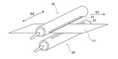
- FIG. 1 is a perspective view showing a slit nozzle and a steel strip in a siliconizing furnace.
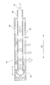
- FIG. 2 is a sectional view showing an example of the slit nozzle of the present invention.
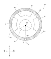
- FIG. 3 is a sectional view taken along line III-III in FIG. 2 showing an example of the current plate.
- FIG. 4 is a cross-sectional view for explaining a region of the current plate where the central angle from the reference line is 27.5 ° or more and 332.5 ° or less.
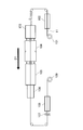
- FIG. 5 is a schematic view showing an example of a continuous production line for high silicon steel strips.
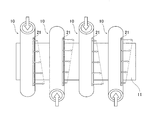
- FIG. 6 is a schematic diagram in the case where the processing gas supply ports of the slit nozzles are arranged so as to alternate in different directions.
- FIG. 1 is a perspective view showing a slit nozzle and a steel strip in a siliconizing furnace.
- FIG. 2 is a sectional view showing an example of the slit nozzle of the present invention.
- FIG. 3 is
- FIG. 7 is a graph showing the evaluation results of Example 1.
- FIG. 8 is a graph showing the evaluation results of Example 2.
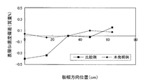
- FIG. 9 is a graph showing the evaluation results of Example 3.
- FIG. 10 is a sectional view showing a conventional slit nozzle.
- FIG. 11 is a schematic diagram in the case where the processing gas supply ports of the slit nozzles are arranged so as to alternate in different directions in the conventional example.
- the present invention is a slit nozzle having a double pipe structure of an inner pipe and an outer pipe, and processing gas is blown out from a discharge port.
- a siliconizing process for siliconizing a steel strip using a slit nozzle will be described, but the present invention is not limited to this, and the effects of the present invention can be obtained. If possible, it can be applied to other uses.
- the slit nozzle may be used when forming a ceramic coating such as TiN on a steel plate, or may be used when performing various chemical vapor deposition treatments on an aluminum plate, a copper plate or the like in addition to steel.
- the slit nozzles 10 each having a processing gas discharge port (slit) 21 are arranged on each of the front surface side and the back surface side of the steel strip 11 in the siliconizing treatment furnace.
- a process gas containing silicon tetrachloride (SiCl 4 ) is blown from the discharge port 21 of 10 to the steel strip 11 at high temperature to allow Si to permeate the steel strip (see FIG. 1). Further, by heat treatment, Si that has permeated the surface of the steel strip is diffused in the plate thickness direction to continuously produce a high silicon steel strip.
- FIG. 2 shows a sectional view of the slit nozzle 10 of FIG.
- the slit nozzle 10 of FIG. 2 is a cross-sectional view showing an example of the slit nozzle of the present invention, and has a double pipe structure of an outer pipe 20 and an inner pipe 30.
- a rectifying plate 40 that adjusts the flow of the processing gas in the slit nozzle 10 is provided inside the slit nozzle 10.
- the outer tube 20 is provided with a processing gas discharge port (slit) 21 in the axial direction D2. Further, one end (the left end in FIG. 2) of the outer tube 20 is closed. Further, in the example shown in FIG. 2, the other end of the outer pipe 20 (the end portion on the right side in FIG. 2) has a hole corresponding to the outer diameter of the inner pipe 30 so that the inner pipe 30 can be arranged inside. However, the other end of the outer tube 20 (the end portion on the right side in FIG. 2) does not necessarily have to be closed.
- the inner pipe 30 is provided inside the outer pipe 20. Further, the inner tube 30 is provided with a processing gas supply port 31 on one end side (right side in FIG. 2), and the other end side (left side in FIG. 2) is inside the closed one end side of the outer tube 20. It is open.
- the processing gas when the processing gas is blown from the supply port 31 of the slit nozzle 10, the processing gas passes through the inside of the inner pipe 30 and the open end 32 of the inner pipe 30 closes the outer pipe 20. It is blown out toward the inside of the one end side. Next, the processing gas is folded back inside the outer pipe 20, flows through the space between the outer pipe 20 and the inner pipe 30, and is finally blown out from the discharge port 21 provided in the outer pipe 20.
- the current plate 40 is provided on the open end surface of the inner pipe 30 and closes the space between the inner pipe 30 and the outer pipe 20.
- the position at which the flow straightening plate 40 is provided is not limited to this, and may be provided at the position B1 between the open end 32 and the end of the discharge port 21 on the open end 32 side (see FIG. 2). However, from the viewpoint of manufacturing efficiency, it is preferably provided on the open end surface of the inner pipe 30 described above.
- FIG. 3 is a cross-sectional view taken along the line III-III in FIG. 2 and shows the surface provided with the current plate 40.
- the discharge port 21 is illustrated by being projected on the surface on which the current plate 40 is provided.
- the straightening vane 40 has a line passing through the axial center C1 of the outer tube 20 and the widthwise center of the discharge port 21 on the surface on which the straightening vane 40 is provided (hereinafter, simply referred to as a reference line L 0.
- the opening 41 is provided only in the region of the rectifying plate 40 whose center angle from 2) is not less than 27.5 ° and not more than 332.5 °.
- the width W2 (see FIG. 3) of the outer tube 20 in the direction perpendicular to the axial direction D2 is preferably 5 mm or more and 20 mm or less from the viewpoint of effectively obtaining the effect of the present invention.
- the width W2 is preferably 15% or less of the outer diameter of the outer tube 20 from the viewpoint of effectively obtaining the effect of the present invention.
- the region of the rectifying plate 40 whose central angle from the reference line L 0 is 27.5 ° or more and 332.5 ° or less is the portion surrounded by the one-dot chain line L2 in FIG.
- FIG. 3 and FIG. 4 a line L 27.5 a position where the center angle is 27.5 ° from a reference line L 0, the center angle from the reference line L 0 and the position of 332.5 °
- the respective lines L 332.5 are indicated by dotted lines.
- the opening 41 is provided only in the region of the rectifying plate 40 where the central angle from the reference line L 0 is 27.5 ° or more and 332.5 ° or less.
- the region where the central angle from the reference line L 0 is 0 ° or more and smaller than 27.5 ° and the region where the central angle from the reference line L 0 is larger than 332.5 ° and smaller than 360 ° are completely straightened by the rectifying plate 40. Is blocked by.
- the processing gas blown from the open end 32 of the inner pipe 30 into the outer pipe 20 is folded back inside the outer pipe 20 and flows toward the discharge port 21, the processing gas is originally concerned.
- the processing gas that has tried to pass through the position of the straightening vane 40 hits the straightening vane 40, and the flow velocity decreases. Therefore, in the conventional slit nozzle 10, the processing gas flowing from the lower portion of the inner pipe 30 toward the processing gas discharge port 21 (which is indicated by an arrow G1 in FIG. 10) is the cause of making the blowing amount of the processing gas uneven.
- the flow rate of the processing gas (shown) can be reduced. It is considered that the variation in the flow rate of the gas blown from the discharge port 21 in the axial direction D2 could be suppressed by this.
- the rectifying plate 40 is provided with three openings 41.
- the number of openings 41 can be changed, and may be, for example, one or two, or four or more.
- the opening 41 is bilaterally symmetrical with respect to the reference line L 0 on the surface on which the rectifying plate 40 is provided. As a result, it is possible to further suppress the variation in the flow rate of the blown gas in the axial direction D2.
- the area ratio R of the opening 41 is defined by the following formula, the area ratio R is 55% or more and 75% or less from the viewpoint of effectively obtaining the effect of the present invention and also obtaining the strength of the current plate 40. It is preferable.
- Area ratio R area of opening / area of the area of the rectifying plate 40 having a central angle from the reference line L 0 of 27.5 ° or more and 332.5 ° or less (area of a portion surrounded by a chain line L2 in FIG. 4)
- the method for producing a high silicon steel strip according to the present invention is performed by a siliconizing method using the slit nozzle 10 according to the present invention.
- Fig. 5 shows an example of a continuous production line for high silicon steel strips by the siliconizing method.
- a steel strip 11 (for example, 3 mass% Si steel strip) fed from a payoff reel 101 passes through a cleaning facility 102, and is heated in a non-oxidizing atmosphere in a heating zone 103 to a temperature at or near the siliconizing treatment temperature. After being heated up to, it is introduced into the siliconizing treatment furnace 104.
- a plurality of slit nozzles 10 of the present invention are arranged at intervals in the furnace length direction (sheet passing direction D1).
- a processing gas containing silicon tetrachloride (SiCl 4 ) which is a reaction gas is blown from both sides of the steel strip 11 through the slit nozzle 10.
- the sprayed SiCl 4 reacts with Fe of the steel strip 11 to enrich the surface layer of the steel strip 11 with Si.
- the steel strip 11 is guided to the diffusion soaking zone 105 and subjected to diffusion heat treatment for diffusing Si in the plate thickness direction in a non-oxidizing atmosphere containing no SiCl 4 .
- the steel strip 11 After being cooled in the cooling zone 106, it is coated with an insulation coating coater 107 and an oven 108 and wound on a tension reel 109 as a product steel strip (for example, a high silicon steel strip having a Si content of 6.5 mass%).
- a product steel strip for example, a high silicon steel strip having a Si content of 6.5 mass%.
- a plurality of slit nozzles 10 are arranged in the siliconizing treatment furnace 104 in the sheet passing direction D1 of the steel strip 11 in the siliconizing treatment furnace 104.
- the processing gas supply ports 31 of the slit nozzle 10 are arranged so as to alternate in different directions (see FIG. 6).
- the slit nozzle group means a group composed of two or more slit nozzles 10.
- a processing gas containing silicon tetrachloride SiCl 4
- SiCl 4 silicon tetrachloride
- the variation in the flow rate of the processing gas amount blown from the discharge port 21 is small in the axial direction D2, so that the slit nozzle 10 has the processing gas supply port 31 in the same direction. It is also possible to arrange them.
- the plurality of slit nozzles 10 arranged in the siliconizing furnace as a whole are arranged in different directions in the axial direction D2 (direction perpendicular to the sheet passing direction D1). It is possible to further suppress variations in the flow rate of the blown gas. Therefore, by the siliconizing treatment method, it is possible to stably manufacture a high silicon steel strip having a small variation in Si concentration in the plate width direction.
- Example 1 Evaluation of position of opening in current plate
- Outer tube (inner diameter: 120 mm, outer diameter: 140 mm, process gas discharge port: 70 cm (axial direction) x 10 mm (direction perpendicular to axial direction)), inner tube (inner diameter: 60 mm, outer diameter: 70 mm), A current plate 1 described below was prepared.
- the inner pipe is arranged inside the outer pipe so that the axial center of the outer pipe and the axial center of the inner pipe coincide with each other, and the rectifying plate 1 is provided on the open end surface of the inner pipe, as shown in FIG.
- the slit nozzle 1 was manufactured.
- the distance between the closed end surface of the outer tube and the open end surface of the inner tube was set to 25 mm.
- the current plate 1 was provided with three openings described below. The sizes of the three openings are all the same.
- Each of the three openings of the current plate 1 has a width W1 of the opening of 1:10 mm and an opening A1 of the central angle of the opening of A1: 50 ° (see FIG. 4).
- the opening is a region in which the angle of the central angle from the reference line L 0 is 35 ° or more and 85 ° or less, 155 ° or more and 205 ° or less, and 275 ° or more and 325 ° or less on the surface provided with the current plate. It is provided in.
- the straightening vanes 2 to 6 were manufactured by changing the angle of the central angle from the reference line L 0 in the region provided with the openings as shown in Table 1. Further, the slit nozzles 2 to 6 were manufactured in the same manner as the slit nozzle 1 except that the current plate 1 was changed to the current plates 2 to 6.
- the width W1 of the opening and the opening A1 of the central angle of the opening of the straightening vanes 2 to 6 are the same as those of the straightening vane 1. Therefore, in each of the current plates 1 to 6, only the position where the opening is provided is changed, and the total area of the three openings is the same.
- the area ratios R of the straightening vanes 1 to 3 of the present invention example were 62.3% respectively.
- Area ratio R Area of opening / Area of the area of the rectifying plate whose central angle from the reference line L 0 is 27.5 ° or more and 332.5 ° or less (area of the portion surrounded by the one-dot chain line L2 in FIG. 4) ⁇ Measurement and evaluation of flow velocity of blown processing gas>
- the processing gas was supplied to the slit nozzles 1 to 6 from the supply port at 2.3 m / sec, and the flow rate of the processing gas blown from the processing gas discharge port was measured. Nitrogen was used as the processing gas for measuring the flow velocity of the processing gas.
- FIG. 7 shows a graph showing the relationship between the axial position (cm), which is the measurement result, and the flow velocity (m / sec) of the processing gas.
- 0 cm corresponds to the end of the discharge port on the side of the supply port of the processing gas.
- 70 cm corresponds to the end of the discharge port on the open end side of the end.
- Example 2 Evaluation of flow rate of processing gas when slit nozzles are alternately arranged
- Two slit nozzles 3 (Examples of the present invention) of Example 1 were arranged with respect to the steel strip such that the supply ports of the processing gas were alternately in different directions (opposite directions).
- the positions of the discharge ports (slits) of the two slit nozzles 1 were arranged so as to coincide with the passing direction of the steel strip.
- one of the gas nozzles supplies the processing gas at a flow rate of 1.5 m / sec and the other at a flow rate of 3.0 m / sec to supply the processing gas from the processing gas supply port.
- the flow velocity of the processing gas blown out from the discharge port was measured. Nitrogen was used as the processing gas in the flow velocity evaluation. Further, the flow velocities of the two slit nozzles at the axial positions were measured, and the sum of the flow velocities at the same axial position was used as the flow velocity of the processing gas at the axial position.
- two slit nozzles 7 provided with no rectifying plate were prepared.
- the slit nozzles 3 (examples of the present invention) are replaced with the slit nozzles 7 in the same manner, and the positions of the discharge ports (slits) of the two slit nozzles 1 are arranged so as to coincide with the passing direction of the steel strip. did.
- the processing gas is supplied into the slit nozzle 7 as in the example of the present invention, Similarly to the example of the present invention, the flow velocity of the processing gas blown from the processing gas discharge port was measured.
- FIG. 8 shows a graph of the measurement results of the flow velocity of the processing gas when the slit nozzle 3 of the present invention example and the slit nozzle 7 of the comparative example are used.
- the graph shown in FIG. 8 shows the relationship between the axial position and the flow velocity of the processing gas.
- the axial position (cm) of the horizontal axis shown in FIG. 8 is 0 cm at the processing gas supply port side of the end portion of the discharge port in the slit nozzle in which the processing gas is supplied at a flow rate of 1.5 m / sec. Corresponds to the end. In addition, 70 cm corresponds to the end of the discharge port of the slit nozzle on the open end side of the inner pipe.
- Example 3 Evaluation of production of high silicon steel strip
- a silicon steel strip (plate thickness: 100 ⁇ m, plate width: 600 mm, Si concentration: 3.4 mass%, Young's modulus: 210 GPa (normal temperature)) was prepared, and the silicon amount was 6. A 5 mass% high silicon steel strip was produced.
- Two processing gas supply ports were arranged on the front surface and the back surface of the steel strip so that the supply ports were alternately in different directions (opposite directions). Further, in the same manner as in Example 2, in two slit nozzles arranged in the sheet passing direction, one of the gas nozzles supplies the processing gas at a flow rate of 1.5 m / sec and the other at a flow rate of 3.0 m / sec.
- a processing gas (processing gas containing silicon tetrachloride) was supplied from the mouth.
- the slit nozzle 3 was changed to the slit nozzle 7, and the others were the same as the example of the present invention.
- Fig. 9 shows the results of measuring the surface layer Si concentration deviation (mass%) in the width direction of the manufactured high silicon steel strip.
- the surface layer Si concentration deviation (mass%) is shown by using the center position in the plate width direction as a reference (0 mass%) and the concentration difference with respect to the Si concentration at the reference position as the surface layer Si concentration deviation (mass%). There is.
- the surface Si concentration was measured by fluorescent X-ray analysis.
- the variation (maximum value-minimum value) in the surface layer Si concentration deviation (mass%) was 0.55 mass%.
- the variation (maximum value-minimum value) of the surface layer Si concentration deviation (mass%) could be suppressed to 0.10 mass%.
- the present invention it is possible to provide a slit nozzle having a double pipe structure capable of suppressing variations in the flow rate of gas blown in the axial direction. It was also found that the slit nozzle of the present invention can be used to stably produce a high-silicon steel strip having a small variation in Si concentration in the plate width direction.
Landscapes
- Chemical & Material Sciences (AREA)
- Engineering & Computer Science (AREA)
- Materials Engineering (AREA)
- Mechanical Engineering (AREA)
- Metallurgy (AREA)
- Organic Chemistry (AREA)
- Chemical Kinetics & Catalysis (AREA)
- Physics & Mathematics (AREA)
- Thermal Sciences (AREA)
- Crystallography & Structural Chemistry (AREA)
- Nozzles (AREA)
- Chemical Vapour Deposition (AREA)
Abstract
Description
軸方向における吹き出されるガス流量のばらつきを抑えることができる二重管構造を有するスリットノズルを提供することである。また、板幅方向におけるSi濃度のばらつきの小さい高珪素鋼帯を安定して製造できる方法を提供することである。
[1]軸方向に処理ガスの吐出口が設けられ、一端が閉塞された外管と、一端側に処理ガスの供給口が設けられ、他端側が前記外管の閉塞された一端側の内部で開放された内管と、の二重管構造を有し、前記供給口から処理ガスが供給されることによって前記吐出口から処理ガスが吹き出されるスリットノズルであって、
前記内管の開放端から、当該開放端側の前記吐出口の端部までの間に、前記内管と前記外管との間を塞ぐ整流板を備え、
前記整流板が設けられた面において、前記外管の軸中心と前記吐出口の幅方向の中心を通る基準線からの中心角が27.5°以上332.5°以下となる前記整流板の領域のみに、開口部が設けられている、スリットノズル。
[2]前記整流板が、前記内管の開放端面に設けられている、[1]に記載のスリットノズル。
[3]前記整流板が設けられた面において、前記開口部が、前記基準線に対して左右対称である、[1]又は[2]に記載のスリットノズル。
[4][1]から[3]のいずれかに記載のスリットノズルを用いた浸珪処理法による高珪素鋼帯の製造方法であって、
前記スリットノズルの複数を、浸珪処理炉内の鋼帯の通板方向に、当該通板方向に隣接するスリットノズル又はスリットノズル群ごとに、前記スリットノズルの処理ガスの供給口が交互に異なる方向となるように配置し、
四塩化ケイ素(SiCl4)を含む処理ガスを、前記処理ガスの供給口から前記スリットノズル内に供給し、前記スリットノズルの処理ガスの吐出口から、通板する鋼帯に前記処理ガスを吹き付ける工程を有する、高珪素鋼帯の製造方法。
次に、本発明の高珪素鋼帯(Si含有量が4質量%以上の鋼帯)の製造方法について説明する。本発明の高珪素鋼帯の製造方法は、本発明のスリットノズル10を用いた浸珪処理法によって行う。
[実施例1:整流板における開口部の位置の評価]
<スリットノズル1の製造>
外管(内径:120mm、外径:140mm、処理ガスの吐出口:70cm(軸方向)×10mm(軸方向に垂直な方向))と、内管(内径:60mm、外径:70mm)と、後述する整流板1を準備した。そして、外管の軸中心と内管の軸中心とが一致するようにして、外管内部に内管を配置し、整流板1を内管の開放端面に設けて、図2に示すようなスリットノズル1を製造した。ここで、外管の閉塞された端部の面と内管の開放端の面との距離は25mmとなるようにした。
<スリットノズル2~6の製造>
整流板1において、開口部が設けられた領域の基準線L0からの中心角の角度を、表1に示すように変更して、整流板2~6を作製した。また、整流板1を整流板2~6に変更した以外はスリットノズル1の製造方法と同様にして、スリットノズル2~6を製造した。

<吹き出され処理ガスの流速の測定と評価>
スリットノズル1~6に対し、供給口から2.3m/secで処理ガスを供給し、処理ガスの吐出口から吹き出される処理ガスの流速を測定した。処理ガスの流速の測定には、処理ガスとして、窒素を用いた。
[実施例2:交互にスリットノズルを配置したときの処理ガスの流速評価]
実施例1のスリットノズル3(本発明例)を、鋼帯に対して、処理ガスの供給口が交互に異なる方向(反対側となる方向)となるように2つ配置した。ここで、2つのスリットノズル1の吐出口(スリット)の位置が、鋼帯の通板方向に一致するように配置した。
本発明例と同様に、処理ガスの吐出口から吹き出される処理ガスの流速を測定した。
[実施例3:高珪素鋼帯の製造評価]
珪素鋼帯(板厚:100μm、板幅:600mm、Si濃度:3.4質量%、ヤング率:210GPa(常温))を準備し、図5に示した連続製造ラインによって、珪素量が6.5質量%の高珪素鋼帯を製造した。
11 鋼帯
20 外管
21 吐出口
30 内管
31 供給口
32 開放端
40 整流板
41 開口部
101 ペイオフリール
102 クリーニング設備
103 加熱帯
104 浸珪処理炉
105 拡散均熱帯
106 冷却帯
107 絶縁皮膜コータ
108 オーブン
109 テンションリール
D1 通板方向
D2 軸方向
L0 基準線
Claims (4)
- 軸方向に処理ガスの吐出口が設けられ、一端が閉塞された外管と、一端側に処理ガスの供給口が設けられ、他端側が前記外管の閉塞された一端側の内部で開放された内管と、の二重管構造を有し、前記供給口から処理ガスが供給されることによって前記吐出口から処理ガスが吹き出されるスリットノズルであって、
前記内管の開放端から、当該開放端側の前記吐出口の端部までの間に、前記内管と前記外管との間を塞ぐ整流板を備え、
前記整流板が設けられた面において、前記外管の軸中心と前記吐出口の幅方向の中心を通る基準線からの中心角が27.5°以上332.5°以下となる前記整流板の領域のみに、開口部が設けられている、スリットノズル。 - 前記整流板が、前記内管の開放端面に設けられている、請求項1に記載のスリットノズル。
- 前記整流板が設けられた面において、前記開口部が、前記基準線に対して左右対称である、請求項1又は2に記載のスリットノズル。
- 請求項1から3のいずれかに記載のスリットノズルを用いた浸珪処理法による高珪素鋼帯の製造方法であって、
前記スリットノズルの複数を、浸珪処理炉内の鋼帯の通板方向に、当該通板方向に隣接するスリットノズル又はスリットノズル群ごとに、前記スリットノズルの処理ガスの供給口が交互に異なる方向となるように配置し、
四塩化ケイ素(SiCl4)を含む処理ガスを、前記処理ガスの供給口から前記スリットノズル内に供給し、前記スリットノズルの処理ガスの吐出口から、通板する鋼帯に前記処理ガスを吹き付ける工程を有する、高珪素鋼帯の製造方法。
Priority Applications (5)
| Application Number | Priority Date | Filing Date | Title |
|---|---|---|---|
| JP2019561341A JP6860088B2 (ja) | 2018-10-26 | 2019-08-13 | スリットノズル及び高珪素鋼帯の製造方法 |
| RU2021111868A RU2766911C1 (ru) | 2018-10-26 | 2019-08-13 | Сопло с нагнетательным отверстием в виде прорези и способ силицирования стальной полосы с высоким содержанием кремния посредством сопла |
| CN201980069758.1A CN112888806A (zh) | 2018-10-26 | 2019-08-13 | 狭缝喷嘴和高硅钢带的制造方法 |
| KR1020217011668A KR102514673B1 (ko) | 2018-10-26 | 2019-08-13 | 슬릿 노즐 및 고규소 강대의 제조 방법 |
| US17/288,811 US12403489B2 (en) | 2018-10-26 | 2019-08-13 | Slit nozzle and method for manufacturing high-silicon steel strip |
Applications Claiming Priority (2)
| Application Number | Priority Date | Filing Date | Title |
|---|---|---|---|
| JP2018201623 | 2018-10-26 | ||
| JP2018-201623 | 2018-10-26 |
Publications (1)
| Publication Number | Publication Date |
|---|---|
| WO2020084873A1 true WO2020084873A1 (ja) | 2020-04-30 |
Family
ID=70330457
Family Applications (1)
| Application Number | Title | Priority Date | Filing Date |
|---|---|---|---|
| PCT/JP2019/031839 Ceased WO2020084873A1 (ja) | 2018-10-26 | 2019-08-13 | スリットノズル及び高珪素鋼帯の製造方法 |
Country Status (7)
| Country | Link |
|---|---|
| US (1) | US12403489B2 (ja) |
| JP (1) | JP6860088B2 (ja) |
| KR (1) | KR102514673B1 (ja) |
| CN (1) | CN112888806A (ja) |
| RU (1) | RU2766911C1 (ja) |
| TW (1) | TWI714238B (ja) |
| WO (1) | WO2020084873A1 (ja) |
Citations (2)
| Publication number | Priority date | Publication date | Assignee | Title |
|---|---|---|---|---|
| JPH08176793A (ja) * | 1994-12-19 | 1996-07-09 | Nkk Corp | 浸珪処理法による高珪素鋼帯の製造方法 |
| JP2015124428A (ja) * | 2013-12-27 | 2015-07-06 | Jfeスチール株式会社 | 化学蒸着処理の原料ガス供給用ノズル |
Family Cites Families (10)
| Publication number | Priority date | Publication date | Assignee | Title |
|---|---|---|---|---|
| SU667250A1 (ru) * | 1977-09-22 | 1979-06-15 | Новосибирский Институт Инженеров Железнодорожного Транспорта | Распылитель |
| SU954442A1 (ru) * | 1981-03-20 | 1982-08-30 | Всесоюзный ордена Ленина научно-исследовательский и проектно-конструкторский институт металлургического машиностроения | Устройство дл охлаждени проката |
| JPS62227078A (ja) | 1986-03-28 | 1987-10-06 | Nippon Kokan Kk <Nkk> | 連続ラインにおける高珪素鋼帯の製造方法 |
| JP2605511B2 (ja) * | 1991-06-28 | 1997-04-30 | 日本鋼管株式会社 | 連続ラインによる高珪素鋼帯の製造方法 |
| JP3257435B2 (ja) * | 1997-02-24 | 2002-02-18 | 日本鋼管株式会社 | 鋼帯の連続浸珪炉 |
| US20020134507A1 (en) * | 1999-12-22 | 2002-09-26 | Silicon Valley Group, Thermal Systems Llc | Gas delivery metering tube |
| JP3300952B1 (ja) * | 2001-03-27 | 2002-07-08 | 株式会社武藤電機 | ブローノズル |
| JP4470556B2 (ja) * | 2004-03-31 | 2010-06-02 | Jfeスチール株式会社 | 連続ラインによる高珪素鋼板の製造方法 |
| CN101884962B (zh) | 2010-07-09 | 2013-05-08 | 中冶京诚工程技术有限公司 | 不堵塞、无气阻的锥面气雾喷嘴及锥面气雾形成方法 |
| US9267080B2 (en) * | 2012-06-27 | 2016-02-23 | Mitsubishi Rayon Co., Ltd. | Carbonization furnace for manufacturing carbon fiber bundle and method for manufacturing carbon fiber bundle |
-
2019
- 2019-08-13 US US17/288,811 patent/US12403489B2/en active Active
- 2019-08-13 CN CN201980069758.1A patent/CN112888806A/zh active Pending
- 2019-08-13 JP JP2019561341A patent/JP6860088B2/ja active Active
- 2019-08-13 WO PCT/JP2019/031839 patent/WO2020084873A1/ja not_active Ceased
- 2019-08-13 KR KR1020217011668A patent/KR102514673B1/ko active Active
- 2019-08-13 RU RU2021111868A patent/RU2766911C1/ru active
- 2019-08-29 TW TW108131101A patent/TWI714238B/zh active
Patent Citations (2)
| Publication number | Priority date | Publication date | Assignee | Title |
|---|---|---|---|---|
| JPH08176793A (ja) * | 1994-12-19 | 1996-07-09 | Nkk Corp | 浸珪処理法による高珪素鋼帯の製造方法 |
| JP2015124428A (ja) * | 2013-12-27 | 2015-07-06 | Jfeスチール株式会社 | 化学蒸着処理の原料ガス供給用ノズル |
Also Published As
| Publication number | Publication date |
|---|---|
| JPWO2020084873A1 (ja) | 2021-02-15 |
| TWI714238B (zh) | 2020-12-21 |
| RU2766911C1 (ru) | 2022-03-16 |
| CN112888806A (zh) | 2021-06-01 |
| US20220008938A1 (en) | 2022-01-13 |
| TW202016319A (zh) | 2020-05-01 |
| KR20210058949A (ko) | 2021-05-24 |
| US12403489B2 (en) | 2025-09-02 |
| KR102514673B1 (ko) | 2023-03-27 |
| JP6860088B2 (ja) | 2021-04-14 |
Similar Documents
| Publication | Publication Date | Title |
|---|---|---|
| CN107109609B (zh) | 合金化热浸镀锌钢板的制造方法 | |
| US12031192B2 (en) | Continuous hot-dip galvanizing apparatus | |
| JP5682626B2 (ja) | 耐炎化熱処理炉 | |
| EP3276037B1 (en) | Method of manufacturing a hot-dip galvanized steel sheet | |
| US10752975B2 (en) | Method of producing galvannealed steel sheet | |
| WO2014129180A1 (ja) | 鋼帯の連続焼鈍装置および連続溶融亜鉛めっき装置 | |
| JP6282981B2 (ja) | 鋼板材の熱処理用の炉のためのノズル装置およびこのようなノズル装置を備えた炉 | |
| EP3369836B1 (en) | Method for manufacturing hot-dip galvanized steel sheet | |
| WO2014129177A1 (ja) | 鋼帯の連続焼鈍装置および連続溶融亜鉛めっき装置 | |
| JP6860088B2 (ja) | スリットノズル及び高珪素鋼帯の製造方法 | |
| JP5812205B2 (ja) | 気体供給吹出ノズル及びこれを用いた耐炎化繊維と炭素繊維との製造方法 | |
| JP5924336B2 (ja) | 化学蒸着処理の原料ガス供給用ノズル | |
| JP2956507B2 (ja) | 浸珪処理法による高珪素鋼帯の製造方法 | |
| JP6128068B2 (ja) | 合金化溶融亜鉛めっき鋼板の製造方法 | |
| JP2025121784A (ja) | 鋼材の処理設備、鋼材の製造設備、鋼材の処理方法、及び鋼材の製造方法 | |
| JP2605511B2 (ja) | 連続ラインによる高珪素鋼帯の製造方法 | |
| JP6604463B1 (ja) | 表面処理設備 | |
| JP2004115830A (ja) | 連続焼鈍及び溶融メッキ兼用設備における冷却設備並びに冷却方法 |
Legal Events
| Date | Code | Title | Description |
|---|---|---|---|
| ENP | Entry into the national phase |
Ref document number: 2019561341 Country of ref document: JP Kind code of ref document: A |
|
| 121 | Ep: the epo has been informed by wipo that ep was designated in this application |
Ref document number: 19876337 Country of ref document: EP Kind code of ref document: A1 |
|
| ENP | Entry into the national phase |
Ref document number: 20217011668 Country of ref document: KR Kind code of ref document: A |
|
| NENP | Non-entry into the national phase |
Ref country code: DE |
|
| 122 | Ep: pct application non-entry in european phase |
Ref document number: 19876337 Country of ref document: EP Kind code of ref document: A1 |
|
| WWG | Wipo information: grant in national office |
Ref document number: 17288811 Country of ref document: US |