WO2020082909A1 - 直线电机及其控制方法 - Google Patents
直线电机及其控制方法 Download PDFInfo
- Publication number
- WO2020082909A1 WO2020082909A1 PCT/CN2019/104635 CN2019104635W WO2020082909A1 WO 2020082909 A1 WO2020082909 A1 WO 2020082909A1 CN 2019104635 W CN2019104635 W CN 2019104635W WO 2020082909 A1 WO2020082909 A1 WO 2020082909A1
- Authority
- WO
- WIPO (PCT)
- Prior art keywords
- assembly
- stator
- mover
- stator assembly
- linear motor
- Prior art date
- Legal status (The legal status is an assumption and is not a legal conclusion. Google has not performed a legal analysis and makes no representation as to the accuracy of the status listed.)
- Ceased
Links
Images



Classifications
-
- H—ELECTRICITY
- H02—GENERATION; CONVERSION OR DISTRIBUTION OF ELECTRIC POWER
- H02K—DYNAMO-ELECTRIC MACHINES
- H02K33/00—Motors with reciprocating, oscillating or vibrating magnet, armature or coil system
- H02K33/16—Motors with reciprocating, oscillating or vibrating magnet, armature or coil system with polarised armatures moving in alternate directions by reversal or energisation of a single coil system
-
- H—ELECTRICITY
- H02—GENERATION; CONVERSION OR DISTRIBUTION OF ELECTRIC POWER
- H02P—CONTROL OR REGULATION OF ELECTRIC MOTORS, ELECTRIC GENERATORS OR DYNAMO-ELECTRIC CONVERTERS; CONTROLLING TRANSFORMERS, REACTORS OR CHOKE COILS
- H02P25/00—Arrangements or methods for the control of AC motors characterised by the kind of AC motor or by structural details
- H02P25/02—Arrangements or methods for the control of AC motors characterised by the kind of AC motor or by structural details characterised by the kind of motor
- H02P25/032—Reciprocating, oscillating or vibrating motors
Definitions
- the present disclosure belongs to the technical field of motors, and particularly relates to a linear motor and its control method.
- linear motor The traditional linear motion adopts the structure of "rotating motor + ball screw".
- the screw structure is used to convert the motion of the rotating motor to the linear motion required by the application, but there are many problems with this transmission method.
- linear motor the linear servo motor (hereinafter referred to as "linear motor") that has re-emerged in recent years has effectively solved the problem of the structure of "rotating motor + ball screw”: the linear motor has no screw, so its length
- screw length the absolute accuracy, repeatability, maximum speed and maximum acceleration of linear motors are higher.
- the working principle of a linear motor can be simply understood as pulling a rotating electrical machine into a straight line along the tangential direction of the motor, the stator part becomes the stator, and the moving rotor part becomes the mover.
- the linear motor products currently on the market fix the stator at a fixed position such as the stator base and arrange the entire length along the moving direction of the mover.
- the slide rail is also fixed, and only the mover moves along the straight line on the slide rail.
- the current linear motor products on the market mostly use windings as movers and permanent magnets as stators, short mover primary and long stator secondary structures.
- the length of the stator in the moving direction is equal to the moving length of the mover, and the price of rare earth permanent magnets is as high as 350 yuan / kg.
- Some high-grade permanent magnets are even higher in price, while the materials such as winding copper wire and steel are only It is 1/8 of the price, so the cost of the stator material composed of permanent magnets is extremely high.
- the technical problem to be solved by the present disclosure is to provide a linear motor and a control method thereof, which can shorten the length of the stator while ensuring the moving length of the mover and reduce the cost of the linear motor.
- a linear motor including a base, a stator assembly and a mover assembly, the stator assembly being slidably disposed on the base.
- the mover assembly is disposed corresponding to the stator assembly, and is slidably disposed on the base.
- a stator guide rail is provided on the base, and the stator assembly is slidably provided on the stator guide rail.
- the stator assembly includes a stator magnetic steel and a stator core disposed on two opposite sides of the stator magnetic steel, and the stator core can be slidably disposed on the stator guide rail.
- a mover slide rail is provided on the base, and the mover assembly is slidably disposed on the mover slide rail.
- a thrust device is further provided on the base.
- the thrust device is used to provide a thrust effect to the stator assembly, so that the stator assembly and the mover assembly move in the same direction.
- the thrust device further includes a trigger unit.
- the trigger unit is disposed on the motion path of the stator assembly, and controls the thrust device to work after the stator assembly triggers the trigger unit.
- a trigger unit is provided at both ends of the base along the sliding direction of the stator assembly.
- the thrust device includes a spring, a hydraulic device, a pneumatic device, a screw drive device, or an electric propulsion device.
- the two mover slide rails there are two mover slide rails.
- the two mover slide rails are arranged in parallel and at the same height.
- the mover assembly is supported by the mover slide rails and suspended on the stator assembly.
- a control method of the above linear motor including:
- S2 energize the mover assembly, move the mover assembly to a preset position, and control the mover assembly and the stator assembly to move in opposite directions;
- step S3 includes:
- the thrust device After receiving the trigger signal of the stator assembly, the thrust device is controlled to push the stator assembly in reverse.
- the linear motor provided by the present disclosure includes a base, a stator assembly, and a mover assembly.
- the stator assembly can be slidably disposed on the base. Since the stator assembly itself can also move relative to the base, the movable feature of the stator assembly can be used to achieve the purpose of achieving a longer movement distance with a shorter stroke, which can greatly shorten the length of the stator assembly and increase the length of the stator assembly.
- the utilization rate reduces the amount of permanent magnets on the stator assembly and reduces the cost of linear motor moving coil materials.
- FIG. 1 is a schematic diagram of a three-dimensional structure of a linear motor according to an embodiment of the present disclosure
- FIG. 2 is a schematic structural diagram of a linear motor according to an embodiment of the present disclosure
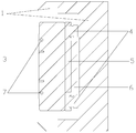
- FIG. 3 is a schematic sectional view taken along the line A-A of FIG. 2;
- FIG. 4 is a flowchart of a control method of a linear motor according to an embodiment of the present disclosure.
- a linear motor includes a base 1, a stator assembly 2 and a mover assembly 3, and the stator assembly 2 is slidably disposed on the base 1.
- the mover assembly 3 is disposed corresponding to the stator assembly 2 and is slidably disposed on the base 1.
- stator assembly 2 itself can also move relative to the base 1, the characteristics of the stator assembly 2 can be used to achieve the purpose of achieving a longer movement distance with a shorter stroke, which can ensure that the movement length of the mover assembly 3 remains unchanged
- the length of the stator assembly is greatly shortened, the utilization rate of the stator assembly in the longitudinal direction is increased, the amount of permanent magnets on the stator assembly is reduced, and the material cost of the linear motor is reduced.
- a stator guide rail 4 is provided on the base 1, and the stator assembly 2 is slidably provided on the stator guide rail 4.
- the stator guide rail 4 is provided at the bottom of the stator assembly 2 and can form a bottom support for the stator assembly 2 so that the stator assembly 2 is suspended relative to the base 1 to reduce the contact area between the stator assembly 2 and the base 1 and reduce the stator assembly 2 Sliding friction.
- the stator assembly 2 includes a stator magnet 5 and stator cores 6 provided on two opposite sides of the stator magnet 5.
- the stator core 6 is slidably provided on the stator guide rail 4.
- the stator core 6 has a T-shaped structure, and the stator guide rails 4 are two. The two sides of the T-shaped structure are respectively supported.
- a groove is provided in the middle of the T-shaped structure for placing the stator magnetic steel 5, wherein the stator magnetic steel 5 is consistent with the height of the top of the stator core 6.
- the stator core 6 is designed to be T-shaped, which can reduce the material consumption of the stator assembly 2 and reasonably use the structure of the stator core 6 to set the stator magnet 5 to reduce the overall volume of the stator assembly 2 and can effectively ensure the stator core 6 Structural strength.
- a mover slide rail 7 is provided on the base 1, and the mover assembly 3 is slidably provided on the mover slide rail 7.
- both ends of the mover slide rail 7 are fixed on the base 1, and the mover slide rail 7 is threaded on the mover assembly 3, while guiding the mover assembly 3,
- the mover assembly 3 plays a supporting role, so that the mover assembly 3 is suspended on the stator assembly 2 to avoid contact between the mover assembly 3 and the stator assembly 2 and can effectively ensure the contact between the mover assembly 3 and the stator assembly 2
- the air gap ensures the movement performance of the mover assembly 3.
- the height of the mover slide rail 7 can be adjusted, so that the air gap between the mover assembly 3 and the stator assembly 2 can be adjusted reasonably, and the magnetic performance of the mover assembly 3 and the stator assembly 2 can be improved.
- the movable runner 7 may be a round rod, a square rod, or other rod-shaped structures.
- a thrust device 8 is also provided on the base 1.
- the thrust device 8 is used to provide a thrust effect to the stator assembly 2, so that the stator assembly 2 and the mover assembly 3 move in the same direction.
- the thrust device 8 includes a spring, a hydraulic device, a pneumatic device, a screw drive device or an electric propulsion device, and may also provide other mechanisms that can provide a thrust effect to the stator assembly 2 so that the stator assembly 2 moves along the moving direction of the mover assembly 3 ⁇ ⁇ Or devices.
- the thrust device 8 further includes a trigger unit, which is disposed on the movement path of the stator assembly 2 and controls the thrust device 8 to work after the stator assembly 2 triggers the trigger unit.
- the trigger unit is a travel switch or a micro switch.
- the trigger unit is connected to the control unit of the thrust device 8 and can send a trigger signal to the control unit, so that the control unit sends out corresponding control signals to control the thrust device 8 to move the stator assembly 2 relative to the base 1.
- Both ends of the base 1 along the sliding direction of the stator assembly 2 are provided with a trigger unit, and a thrust device 8 can provide a thrust function for the stator assembly 2 to ensure the stator when the stator assembly 2 moves to a preset position at both ends of the base 1
- the assembly 2 can move along the base 1 a sufficient distance, and the movement of the stator assembly 2 shortens the amount of permanent magnets on the stator assembly 2 and reduces the cost of the stator assembly 2.
- the stator assembly 2 and the mover assembly 3 After the linear motor is energized, the stator assembly 2 and the mover assembly 3 generate thrust due to the interaction of electromagnetic induction.
- the mover assembly 3 moves horizontally along the mover slide 7 in the specified direction, and the stator assembly 2 is affected by the mover assembly 3
- the force in the opposite direction moves in the opposite direction to the mover assembly 3.
- the thrust device 8 triggers and pushes the stator assembly 2 in the reverse direction, so that The movement direction of the stator assembly 2 is consistent with the movement direction of the mover assembly 3.
- the motor driver inputs the motor coil winding signal to generate a reverse traveling wave magnetic field, and the mover assembly 3 is subjected to the reverse magnetic field
- the reverse horizontal movement starts, and at this time, the stator assembly 2 maintains the reverse horizontal movement of the stator assembly 2 and the mover assembly 3 through the thrust device 8 at the other end, and finally achieves the effect of the horizontal reciprocating movement of the linear motor.
- a control method of the above linear motor includes: S1: power on the linear motor; S2: power on the mover subassembly 3, so that the mover subassembly 3 is preset Position movement, control the mover assembly 3 and the stator assembly 2 to move in opposite directions; S3: detect the movement position of the stator assembly 2, when the stator assembly 2 moves to the preset position, apply a reverse thrust to the stator assembly 2 to make the stator assembly 2 Move in the same direction as mover assembly 3; S4: When mover assembly 3 moves to a preset position, energize mover assembly 3 in reverse to control mover assembly 3 and stator assembly 2 to move in opposite directions; S5: Repeat Steps S3 and S4.
- stator assembly 2 After the motor starts to be energized, an interaction force is generated between the mover assembly 3 and the stator assembly 2 due to electromagnetic induction, and the two move along the mover slide rail 7 and the stator guide rail 4 in opposite directions, respectively.
- the stator assembly 2 will move to one end of the linear base 1 of the motor, and the stator assembly 2 triggers the thrust device 8 installed inside the marble base 1 at one end of the motor by extrusion or the like.
- the thrust device 8 is triggered to generate a thrust opposite to the original movement direction of the stator assembly 2.
- the stator assembly 2 that is pushed in the reverse direction by the thrust device 8 changes the direction of movement and moves in the opposite direction, which is consistent with the movement direction of the mover assembly 3.
- the stator assembly 2 "transmits" the thrust force of the thrust device 8 to the mover assembly 3, so that the mover assembly 3 can finally move to the target position, which is completed
- the triggering process of the thrust device 8 it can be reciprocated in accordance with the above control process thereafter.
- Step S3 includes: detecting the trigger signal of the stator assembly 2; after receiving the trigger signal of the stator assembly 2, controlling the thrust device 8 to push the stator assembly 2 in reverse.
Landscapes
- Engineering & Computer Science (AREA)
- Power Engineering (AREA)
- Linear Motors (AREA)
Abstract
本公开提供一种直线电机及其控制方法。该直线电机包括基座(1)、定子组件(2)和动子组件(3),定子组件(2)能够滑动地设置在基座(1)上。根据本公开的直线电机,能够在保证动子的运动长度的同时缩短定子的长度,降低直线电机成本。
Description
相关申请
本公开要求2018年10月23日申请的,申请号为201811237230.4,名称为“直线电机及其控制方法”的中国专利申请的优先权,在此将其全文引入作为参考。
本公开属于电机技术领域,尤其涉及一种直线电机及其控制方法。
传统直线运动采用“旋转电机+滚珠丝杠”的结构,利用丝杠结构将旋转电机旋转方向的运动转换为应用所需的直线运动,但是这种传动方式存在着诸多问题。随着相关技术的进步,近些年重新兴起的直线伺服电机(以下简称“直线电机”)有效地解决了“旋转电机+滚珠丝杠”结构的问题:直线电机没有丝杠、所以长度不受丝杠长度的限制,直线电机的绝对精度、重复精度、最大速度和最大加速度更高等等。
直线电机的工作原理可以简单理解成将旋转电机沿电机切向拉成直线,定子部分成为定子,移动的转子部分成为动子。一方面,目前市场上的直线电机产品,都是将定子固定在定子基座等固定位置并沿动子运动方向布置整个长度,滑轨也固定,仅动子在滑轨上沿直线移动。另一方面,出于电机物料成本和生产工艺的考量,目前市场上的直线电机产品多将绕组作为动子、永磁体作为定子的短动子初级、长定子次级的结构。综上两点,定子沿运动方向的长度等于动子的运动长度,并且稀土永磁体的价格高达350元/kg,一些高牌号的永磁体价格甚至更高,而绕组铜线和钢等材料仅为其1/8的价格,所以由永磁体组成的定子物料成本极高。
发明内容
因此,本公开要解决的技术问题在于提供一种直线电机及其控制方法,能够在保证动子的运动长度的同时缩短定子的长度,降低直线电机成本。
为了解决上述问题,本公开提供一种直线电机,包括基座、定子组件和动子组件,定子组件能够滑动地设置在基座上。
在其中一个实施例中,动子组件对应定子组件设置,并且能够滑动地设置在基座上。
在其中一个实施例中,基座上设置有定子导轨,定子组件能够滑动地设置在定子导轨上。
在其中一个实施例中,定子组件包括定子磁钢和设置在定子磁钢的两个相对侧的定子铁芯,定子铁芯能够滑动地设置在定子导轨上。
在其中一个实施例中,基座上设置有动子滑轨,动子组件能够滑动地设置在动子滑轨上。
在其中一个实施例中,基座上还设置有推力装置,推力装置用于为定子组件提供推力作用,以使定子组件与动子组件同向运动。
在其中一个实施例中,推力装置还包括触发单元,触发单元设置在定子组件的运动路径上,并在定子组件触发触发单元后控制推力装置工作。
在其中一个实施例中,基座沿定子组件滑动方向的两端均设置有触发单元。
在其中一个实施例中,推力装置包括弹簧、液压装置、气压装置、螺杆驱动装置或电力推动装置。
在其中一个实施例中,动子滑轨为两个,两个动子滑轨平行设置,且位于同一高度上,动子组件通过动子滑轨支撑并悬浮于定子组件上。
根据本公开的另一方面,提供了一种上述的直线电机的控制方法,包括:
S1:给直线电机上电;
S2:给动子组件通电,使动子组件向预设位置运动,控制动子组件和定子组件沿相反方向运动;
S3:检测定子组件的运动位置,当定子组件运动到预设位置时,对定子组件施加反向推力,使定子组件和动子组件同向运动;
S4:当动子组件运动到预设位置后,对动子组件反向通电,控制动子组件和定子组件沿相反方向运动;
S5:重复步骤S3和S4。
在其中一个实施例中,步骤S3包括:
检测定子组件的触发信号;
当接收到定子组件的触发信号后,控制推力装置反向推动定子组件。
本公开提供的直线电机,包括基座、定子组件和动子组件,定子组件能够滑动地设置在基座上。由于定子组件本身也能够相对于基座运动,因此可以利用定子组件能够运动的特点达到以较短行程实现较长运动距离的目的,可极大地缩短定子组件的长度尺寸,提高定子组件长度方向的利用率,降低定子组件上永磁体的用量,减少直线电机动圈式材料成 本。
图1为本公开实施例的直线电机的立体结构示意图;
图2为本公开实施例的直线电机的结构示意图;
图3为图2的A-A向剖视结构示意图;
图4本公开实施例的直线电机的控制方法流程图。
附图标记表示为:
1、基座;2、定子组件;3、动子组件;4、定子导轨;5、定子磁钢;6、定子铁芯;7、动子滑轨;8、推力装置
结合参见图1至图3所示,根据本公开的实施例,直线电机包括基座1、定子组件2和动子组件3,定子组件2能够滑动地设置在基座1上。在其中一个实施例中,动子组件3对应定子组件2设置,并且能够滑动地设置在基座1上。
由于定子组件2本身也能够相对于基座1运动,因此可以利用定子组件2能够运动的特点达到以较短行程实现较长运动距离的目的,可在保证动子组件3运动长度不变的情况下极大地缩短定子组件的长度尺寸,提高定子组件长度方向的利用率,降低定子组件上永磁体的用量,减少直线电机材料成本。
基座1上设置有定子导轨4,定子组件2能够滑动地设置在定子导轨4上。该定子导轨4设置在定子组件2的底部,能够对定子组件2形成底部支撑,使得定子组件2相对于基座1悬空,减少定子组件2与基座1之间的接触面积,降低定子组件2的滑动摩擦。
在本实施例中,定子组件2包括定子磁钢5和设置在定子磁钢5的两个相对侧的定子铁芯6,定子铁芯6能够滑动地设置在定子导轨4上。其中定子铁芯6为T字形结构,定子导轨4为两个,分别支撑的T字形结构的两侧,在T字形结构的中部设置有凹槽,用于放置定子磁钢5,其中定子磁钢5与定子铁芯6的顶部高度一致。将定子铁芯6设计为T字形,能够减少定子组件2的材料用量,合理利用定子铁芯6的结构进行定子磁钢5的设置,减少定子组件2的整体体积,并能够有效保证定子铁芯6的结构强度。
基座1上设置有动子滑轨7,动子组件3能够滑动地设置在动子滑轨7上。在本实施例中,动子滑轨7的两端固定在基座1上,且动子滑轨7穿设在动子组件3上,在对动子组件3起到导向作用的同时,对动子组件3起到支撑作用,使得动子组件3悬浮于定子组 件2上,避免动子组件3与定子组件2之间发生接触,并能够有效保证动子组件3与定子组件2之间的气隙,保证动子组件3的运动性能。动子滑轨7的高度可以调节,从而能够合理调节动子组件3与定子组件2之间的气隙,提高动子组件3与定子组件2配合的磁性能。动子滑轨7为两个,两个动子滑轨7平行设置,且位于同一高度上。动子滑轨7可以为圆杆,也可以为方杆,或者是其它的杆状结构。
基座1上还设置有推力装置8,推力装置8用于为定子组件2提供推力作用,以使定子组件2与动子组件3同向运动。该推力装置8包括弹簧、液压装置、气压装置、螺杆驱动装置或电力推动装置,也可以为其它能够为定子组件2提供推力作用,使得定子组件2沿着动子组件3的运动方向运动的机构或装置。
推力装置8还包括触发单元,触发单元设置在定子组件2的运动路径上,并在定子组件2触发触发单元后控制推力装置8工作。该触发单元为行程开关或者微动开关等。该触发单元与推力装置8的控制单元连接,能够将触发信号输送给控制单元,从而使得控制单元发出相应的控制信号,控制推力装置8推动定子组件2相对于基座1运动。
基座1沿定子组件2滑动方向的两端均设置有触发单元,可以在定子组件2运动至基座1两端的预设位置处,均有推力装置8为定子组件2提供推力作用,保证定子组件2能够沿着基座1运动足够距离,通过定子组件2的运动缩短定子组件2上永磁体的用量,降低定子组件2的成本。
给直线电机通电后,定子组件2和动子组件3因为电磁感应产生相互作用的推力,动子组件3沿着动子滑轨7朝指定方向水平移动,而定子组件2由于受到动子组件3的相反方向作用力而沿着与动子组件3相反方向运动,当定子组件2运动到预设位置时,会挤压触碰推力装置8,推力装置8触发并反向推动定子组件2,使定子组件2的运动方向与动子组件3的运动方向一致,当动子组件3运动至极限位置处,电机驱动器输入电机线圈绕组信号产生反向行波磁场,动子组件3受反向磁场作用开始反向水平移动,此时定子组件2通过另一端的推力装置8使定子组件2与动子组件3仍保持反向水平运动,最终实现直线电机水平往复运动的效果。
结合参见图4所示,根据本公开的实施例,一种上述的直线电机的控制方法包括:S1:给直线电机上电;S2:给动子组件3通电,使动子组件3向预设位置运动,控制动子组件3和定子组件2沿相反方向运动;S3:检测定子组件2的运动位置,当定子组件2运动到预设位置时,对定子组件2施加反向推力,使定子组件2和动子组件3同向运动;S4:当动子组件3运动到预设位置后,对动子组件3反向通电,控制动子组件3和定子组件2沿相反方向运动;S5:重复步骤S3和S4。
电机开始通电后,动子组件3和定子组件2之间由于电磁感应产生相互作用力,二者分别沿动子滑轨7和定子导轨4向相背方向运动。其中定子组件2会运动到电机直线基座1的一端,定子组件2通过挤压等方式触发安装在电机一端大理石基座1内侧的推力装置8。推力装置8被触发,产生与定子组件2原运动方向相反的推力。被推力装置8反向推动的定子组件2即改变运动方向,向相反方向运动,即与动子组件3运动方向一致。再通过动子组件3和定子组件2之间的相互作用力,定子组件2将推力装置8的推力“传递”给动子组件3,使得动子组件3最终能运动到目标位置,如此便完成了一次推力装置8的触发过程,此后可按照上述控制过程往复进行。
步骤S3包括:检测定子组件2的触发信号;当接收到定子组件2的触发信号后,控制推力装置8反向推动定子组件2。
本领域的技术人员容易理解的是,在不冲突的前提下,上述各有利方式可以自由地组合、叠加。
以上仅为本公开的较佳实施例而已,并不用以限制本公开,凡在本公开的精神和原则之内所作的任何修改、等同替换和改进等,均应包含在本公开的保护范围之内。以上仅是本公开的优选实施方式,应当指出,对于本技术领域的普通技术人员来说,在不脱离本公开技术原理的前提下,还可以做出若干改进和变型,这些改进和变型也应视为本公开的保护范围。
Claims (12)
- 一种直线电机,包括基座(1)、定子组件(2)和动子组件(3),所述定子组件(2)能够滑动地设置在所述基座(1)上。
- 根据权利要求1所述的直线电机,其特征在于,所述动子组件(3)对应所述定子组件(2)设置,并且能够滑动地设置在所述基座(1)上。
- 根据权利要求1所述的直线电机,其特征在于,所述基座(1)上设置有定子导轨(4),所述定子组件(2)能够滑动地设置在所述定子导轨(4)上。
- 根据权利要求3所述的直线电机,其特征在于,所述定子组件(2)包括定子磁钢(5)和设置在所述定子磁钢(5)的两个相对侧的定子铁芯(6),所述定子铁芯(6)能够滑动地设置在所述定子导轨(4)上。
- 根据权利要求2所述的直线电机,其特征在于,所述基座(1)上设置有动子滑轨(7),所述动子组件(3)能够滑动地设置在所述动子滑轨(7)上。
- 根据权利要求1至5中任一项所述的直线电机,其特征在于,所述基座(1)上还设置有推力装置(8),所述推力装置(8)用于为所述定子组件(2)提供推力作用,以使所述定子组件(2)与所述动子组件(3)同向运动。
- 根据权利要求6所述的直线电机,其特征在于,所述推力装置(8)还包括触发单元,所述触发单元设置在所述定子组件(2)的运动路径上,并在所述定子组件(2)触发所述触发单元后控制所述推力装置(8)工作。
- 根据权利要求7所述的直线电机,其特征在于,所述基座(1)沿所述定子组件(2)滑动方向的两端均设置有所述触发单元。
- 根据权利要求6所述的直线电机,其特征在于,所述推力装置(8)包括弹簧、液压装置、气压装置、螺杆驱动装置或电力推动装置。
- 根据权利要求5所述的直线电机,其特征在于,所述动子滑轨(7)为两个,两个所述动子滑轨(7)平行设置,且位于同一高度上,所述动子组件(3)通过所述动子滑轨(7)支撑并悬浮于所述定子组件(2)上。
- 一种应用于权利要求1至10中任一项所述的直线电机的控制方法,包括:S1:给直线电机上电;S2:给动子组件(3)通电,使动子组件(3)向预设位置运动,控制动子组件(3)和定子组件(2)沿相反方向运动;S3:检测定子组件(2)的运动位置,当定子组件(2)运动到预设位置时,对定子组件(2)施加反向推力,使定子组件(2)和动子组件(3)同向运动;S4:当动子组件(3)运动到预设位置后,对所述动子组件(3)反向通电,控制动子组件(3)和定子组件(2)沿相反方向运动;S5:重复步骤S3和S4。
- 根据权利要求10所述的控制方法,其特征在于,所述步骤S3包括:检测定子组件(2)的触发信号;当接收到定子组件(2)的触发信号后,控制推力装置(8)反向推动定子组件(2)。
Applications Claiming Priority (2)
| Application Number | Priority Date | Filing Date | Title |
|---|---|---|---|
| CN201811237230.4A CN109038995A (zh) | 2018-10-23 | 2018-10-23 | 直线电机及其控制方法 |
| CN201811237230.4 | 2018-10-23 |
Publications (1)
| Publication Number | Publication Date |
|---|---|
| WO2020082909A1 true WO2020082909A1 (zh) | 2020-04-30 |
Family
ID=64613827
Family Applications (1)
| Application Number | Title | Priority Date | Filing Date |
|---|---|---|---|
| PCT/CN2019/104635 Ceased WO2020082909A1 (zh) | 2018-10-23 | 2019-09-06 | 直线电机及其控制方法 |
Country Status (2)
| Country | Link |
|---|---|
| CN (1) | CN109038995A (zh) |
| WO (1) | WO2020082909A1 (zh) |
Families Citing this family (2)
| Publication number | Priority date | Publication date | Assignee | Title |
|---|---|---|---|---|
| CN109038995A (zh) * | 2018-10-23 | 2018-12-18 | 珠海格力电器股份有限公司 | 直线电机及其控制方法 |
| CN116418190A (zh) * | 2023-04-18 | 2023-07-11 | 上海世禹精密设备股份有限公司 | 高速移动避震方法及装置 |
Citations (3)
| Publication number | Priority date | Publication date | Assignee | Title |
|---|---|---|---|---|
| GB2165171A (en) * | 1984-09-25 | 1986-04-09 | Hiroshi Teramachi | X-y table assembly |
| CN205160337U (zh) * | 2015-10-26 | 2016-04-13 | 物必达智能设备南通有限公司 | 一种快递转运交叉带式小车移动直线电机 |
| CN109038995A (zh) * | 2018-10-23 | 2018-12-18 | 珠海格力电器股份有限公司 | 直线电机及其控制方法 |
Family Cites Families (4)
| Publication number | Priority date | Publication date | Assignee | Title |
|---|---|---|---|---|
| EP0393994B1 (en) * | 1989-04-17 | 1994-06-15 | SHARP Corporation | A linear driving apparatus |
| JP3382061B2 (ja) * | 1995-05-31 | 2003-03-04 | 松下電工株式会社 | リニア振動モータ |
| KR101258407B1 (ko) * | 2011-12-06 | 2013-04-26 | 주식회사 져스텍 | 반발력 보상 선형 구동 시스템 |
| CN209030063U (zh) * | 2018-10-23 | 2019-06-25 | 珠海格力电器股份有限公司 | 直线电机 |
-
2018
- 2018-10-23 CN CN201811237230.4A patent/CN109038995A/zh not_active Withdrawn
-
2019
- 2019-09-06 WO PCT/CN2019/104635 patent/WO2020082909A1/zh not_active Ceased
Patent Citations (3)
| Publication number | Priority date | Publication date | Assignee | Title |
|---|---|---|---|---|
| GB2165171A (en) * | 1984-09-25 | 1986-04-09 | Hiroshi Teramachi | X-y table assembly |
| CN205160337U (zh) * | 2015-10-26 | 2016-04-13 | 物必达智能设备南通有限公司 | 一种快递转运交叉带式小车移动直线电机 |
| CN109038995A (zh) * | 2018-10-23 | 2018-12-18 | 珠海格力电器股份有限公司 | 直线电机及其控制方法 |
Also Published As
| Publication number | Publication date |
|---|---|
| CN109038995A (zh) | 2018-12-18 |
Similar Documents
| Publication | Publication Date | Title |
|---|---|---|
| CN109516336B (zh) | 直线驱动装置、安全钳装置及电梯系统的控制方法 | |
| JP2014506445A (ja) | リニアモータを有するピペット装置 | |
| TW201705655A (zh) | 直線運動線性模組及應用該直線運動線性模組的位置控制伺服系統 | |
| WO2015078287A1 (zh) | 平板音圈电机 | |
| WO2020082909A1 (zh) | 直线电机及其控制方法 | |
| CN211981722U (zh) | 一种采用单支导轨承载的直线电机模组 | |
| CN109889014A (zh) | 一种初级绕组分段永磁直线同步电机 | |
| CN102118084B (zh) | 一种永磁体的组装装置和组装方法 | |
| CN102891585A (zh) | 一种单边型动磁直线电机 | |
| KR101512838B1 (ko) | 듀얼 포스 보이스 코일 선형 액추에이터 | |
| CN105071574A (zh) | 一种高速多相电励磁同步直线电机 | |
| CN209030063U (zh) | 直线电机 | |
| CN101436811A (zh) | 新式永磁机 | |
| CN103268818B (zh) | 变压器铁芯压模 | |
| CN205465198U (zh) | 直接磁悬浮直线同步电动机磁悬浮龙门立柱 | |
| CN101860173B (zh) | 用于数控进给平台的直接磁悬浮永磁直线同步电动机 | |
| CN205376443U (zh) | 一种电磁操动机构及使用该机构的断路器 | |
| CN220475586U (zh) | 一种直线电机 | |
| CN212542074U (zh) | 一种新型直流电磁机构 | |
| CN103057284B (zh) | 一种用于驱动打印头的驱动装置 | |
| CN212793934U (zh) | 一种紧凑型高精度直线运动定位工作台 | |
| CN106026608A (zh) | 一种双边直线步进电机 | |
| CN201041980Y (zh) | 永磁机 | |
| CN108550495A (zh) | 双单稳态组合的可实现短时闭合的永磁操动机构及方法 | |
| CN110829886B (zh) | 一种基于gmm的宏微线性驱动器 |
Legal Events
| Date | Code | Title | Description |
|---|---|---|---|
| 121 | Ep: the epo has been informed by wipo that ep was designated in this application |
Ref document number: 19876699 Country of ref document: EP Kind code of ref document: A1 |
|
| NENP | Non-entry into the national phase |
Ref country code: DE |
|
| 122 | Ep: pct application non-entry in european phase |
Ref document number: 19876699 Country of ref document: EP Kind code of ref document: A1 |