WO2020080481A1 - Coil mounting structure - Google Patents
Coil mounting structure Download PDFInfo
- Publication number
- WO2020080481A1 WO2020080481A1 PCT/JP2019/040950 JP2019040950W WO2020080481A1 WO 2020080481 A1 WO2020080481 A1 WO 2020080481A1 JP 2019040950 W JP2019040950 W JP 2019040950W WO 2020080481 A1 WO2020080481 A1 WO 2020080481A1
- Authority
- WO
- WIPO (PCT)
- Prior art keywords
- coil
- motor rotation
- motor
- circumferential direction
- turns
- Prior art date
Links
- 238000004804 winding Methods 0.000 claims abstract description 13
- 230000002093 peripheral effect Effects 0.000 claims description 20
- 239000004020 conductor Substances 0.000 claims description 16
- 239000000463 material Substances 0.000 description 5
- -1 amide imide Chemical class 0.000 description 3
- XEEYBQQBJWHFJM-UHFFFAOYSA-N Iron Chemical compound [Fe] XEEYBQQBJWHFJM-UHFFFAOYSA-N 0.000 description 2
- 230000001154 acute effect Effects 0.000 description 2
- 238000005452 bending Methods 0.000 description 2
- 239000002826 coolant Substances 0.000 description 2
- 229910052751 metal Inorganic materials 0.000 description 2
- 239000002184 metal Substances 0.000 description 2
- QNRATNLHPGXHMA-XZHTYLCXSA-N (r)-(6-ethoxyquinolin-4-yl)-[(2s,4s,5r)-5-ethyl-1-azabicyclo[2.2.2]octan-2-yl]methanol;hydrochloride Chemical compound Cl.C([C@H]([C@H](C1)CC)C2)CN1[C@@H]2[C@H](O)C1=CC=NC2=CC=C(OCC)C=C21 QNRATNLHPGXHMA-XZHTYLCXSA-N 0.000 description 1
- 229910001369 Brass Inorganic materials 0.000 description 1
- RYGMFSIKBFXOCR-UHFFFAOYSA-N Copper Chemical compound [Cu] RYGMFSIKBFXOCR-UHFFFAOYSA-N 0.000 description 1
- FYYHWMGAXLPEAU-UHFFFAOYSA-N Magnesium Chemical compound [Mg] FYYHWMGAXLPEAU-UHFFFAOYSA-N 0.000 description 1
- 239000004677 Nylon Substances 0.000 description 1
- 239000004696 Poly ether ether ketone Substances 0.000 description 1
- 239000004642 Polyimide Substances 0.000 description 1
- 229910000831 Steel Inorganic materials 0.000 description 1
- HCHKCACWOHOZIP-UHFFFAOYSA-N Zinc Chemical compound [Zn] HCHKCACWOHOZIP-UHFFFAOYSA-N 0.000 description 1
- NIXOWILDQLNWCW-UHFFFAOYSA-N acrylic acid group Chemical group C(C=C)(=O)O NIXOWILDQLNWCW-UHFFFAOYSA-N 0.000 description 1
- 229910052782 aluminium Inorganic materials 0.000 description 1
- XAGFODPZIPBFFR-UHFFFAOYSA-N aluminium Chemical compound [Al] XAGFODPZIPBFFR-UHFFFAOYSA-N 0.000 description 1
- JUPQTSLXMOCDHR-UHFFFAOYSA-N benzene-1,4-diol;bis(4-fluorophenyl)methanone Chemical compound OC1=CC=C(O)C=C1.C1=CC(F)=CC=C1C(=O)C1=CC=C(F)C=C1 JUPQTSLXMOCDHR-UHFFFAOYSA-N 0.000 description 1
- 239000010951 brass Substances 0.000 description 1
- 238000001816 cooling Methods 0.000 description 1
- 229910052802 copper Inorganic materials 0.000 description 1
- 239000010949 copper Substances 0.000 description 1
- 210000003298 dental enamel Anatomy 0.000 description 1
- 238000005516 engineering process Methods 0.000 description 1
- 230000017525 heat dissipation Effects 0.000 description 1
- 229920006015 heat resistant resin Polymers 0.000 description 1
- 229910052742 iron Inorganic materials 0.000 description 1
- 238000010030 laminating Methods 0.000 description 1
- 239000011777 magnesium Substances 0.000 description 1
- 229910052749 magnesium Inorganic materials 0.000 description 1
- 238000002844 melting Methods 0.000 description 1
- 230000008018 melting Effects 0.000 description 1
- 229910001172 neodymium magnet Inorganic materials 0.000 description 1
- 229920001778 nylon Polymers 0.000 description 1
- 229920002530 polyetherether ketone Polymers 0.000 description 1
- 229920001721 polyimide Polymers 0.000 description 1
- 238000004080 punching Methods 0.000 description 1
- 239000003507 refrigerant Substances 0.000 description 1
- 229920005989 resin Polymers 0.000 description 1
- 239000011347 resin Substances 0.000 description 1
- 229910052710 silicon Inorganic materials 0.000 description 1
- 239000010703 silicon Substances 0.000 description 1
- 239000002356 single layer Substances 0.000 description 1
- 239000010959 steel Substances 0.000 description 1
- 238000003466 welding Methods 0.000 description 1
- 229910052725 zinc Inorganic materials 0.000 description 1
- 239000011701 zinc Substances 0.000 description 1
Images

Classifications
-
- H—ELECTRICITY
- H02—GENERATION; CONVERSION OR DISTRIBUTION OF ELECTRIC POWER
- H02K—DYNAMO-ELECTRIC MACHINES
- H02K3/00—Details of windings
- H02K3/04—Windings characterised by the conductor shape, form or construction, e.g. with bar conductors
- H02K3/18—Windings for salient poles
-
- H—ELECTRICITY
- H02—GENERATION; CONVERSION OR DISTRIBUTION OF ELECTRIC POWER
- H02K—DYNAMO-ELECTRIC MACHINES
- H02K3/00—Details of windings
- H02K3/04—Windings characterised by the conductor shape, form or construction, e.g. with bar conductors
- H02K3/28—Layout of windings or of connections between windings
-
- H—ELECTRICITY
- H01—ELECTRIC ELEMENTS
- H01F—MAGNETS; INDUCTANCES; TRANSFORMERS; SELECTION OF MATERIALS FOR THEIR MAGNETIC PROPERTIES
- H01F5/00—Coils
-
- H—ELECTRICITY
- H02—GENERATION; CONVERSION OR DISTRIBUTION OF ELECTRIC POWER
- H02K—DYNAMO-ELECTRIC MACHINES
- H02K1/00—Details of the magnetic circuit
- H02K1/06—Details of the magnetic circuit characterised by the shape, form or construction
- H02K1/12—Stationary parts of the magnetic circuit
- H02K1/16—Stator cores with slots for windings
- H02K1/165—Shape, form or location of the slots
-
- H—ELECTRICITY
- H02—GENERATION; CONVERSION OR DISTRIBUTION OF ELECTRIC POWER
- H02K—DYNAMO-ELECTRIC MACHINES
- H02K1/00—Details of the magnetic circuit
- H02K1/06—Details of the magnetic circuit characterised by the shape, form or construction
- H02K1/22—Rotating parts of the magnetic circuit
- H02K1/32—Rotating parts of the magnetic circuit with channels or ducts for flow of cooling medium
-
- H—ELECTRICITY
- H02—GENERATION; CONVERSION OR DISTRIBUTION OF ELECTRIC POWER
- H02K—DYNAMO-ELECTRIC MACHINES
- H02K3/00—Details of windings
- H02K3/04—Windings characterised by the conductor shape, form or construction, e.g. with bar conductors
- H02K3/12—Windings characterised by the conductor shape, form or construction, e.g. with bar conductors arranged in slots
-
- H—ELECTRICITY
- H02—GENERATION; CONVERSION OR DISTRIBUTION OF ELECTRIC POWER
- H02K—DYNAMO-ELECTRIC MACHINES
- H02K3/00—Details of windings
- H02K3/46—Fastening of windings on the stator or rotor structure
- H02K3/48—Fastening of windings on the stator or rotor structure in slots
-
- H—ELECTRICITY
- H02—GENERATION; CONVERSION OR DISTRIBUTION OF ELECTRIC POWER
- H02K—DYNAMO-ELECTRIC MACHINES
- H02K1/00—Details of the magnetic circuit
- H02K1/06—Details of the magnetic circuit characterised by the shape, form or construction
- H02K1/12—Stationary parts of the magnetic circuit
- H02K1/14—Stator cores with salient poles
- H02K1/146—Stator cores with salient poles consisting of a generally annular yoke with salient poles
- H02K1/148—Sectional cores
-
- H—ELECTRICITY
- H02—GENERATION; CONVERSION OR DISTRIBUTION OF ELECTRIC POWER
- H02K—DYNAMO-ELECTRIC MACHINES
- H02K2203/00—Specific aspects not provided for in the other groups of this subclass relating to the windings
- H02K2203/09—Machines characterised by wiring elements other than wires, e.g. bus rings, for connecting the winding terminations
-
- H—ELECTRICITY
- H02—GENERATION; CONVERSION OR DISTRIBUTION OF ELECTRIC POWER
- H02K—DYNAMO-ELECTRIC MACHINES
- H02K2213/00—Specific aspects, not otherwise provided for and not covered by codes H02K2201/00 - H02K2211/00
- H02K2213/03—Machines characterised by numerical values, ranges, mathematical expressions or similar information
-
- H—ELECTRICITY
- H02—GENERATION; CONVERSION OR DISTRIBUTION OF ELECTRIC POWER
- H02K—DYNAMO-ELECTRIC MACHINES
- H02K3/00—Details of windings
- H02K3/46—Fastening of windings on the stator or rotor structure
- H02K3/52—Fastening salient pole windings or connections thereto
- H02K3/521—Fastening salient pole windings or connections thereto applicable to stators only
- H02K3/522—Fastening salient pole windings or connections thereto applicable to stators only for generally annular cores with salient poles
Definitions
- the present invention relates to a winding shaft having a shape in which a columnar tooth portion projectingly provided on an inner peripheral surface of an annular yoke portion of a stator of a motor and a plate-shaped conductive wire extending in a band shape are bent in the width direction and wound.
- the present invention relates to a coil mounting structure having first to n-th turns (n is an integer of 2 or more) stacked in the direction, and a coil mounted on the teeth portion.
- Patent Document 1 discloses a coil having first to n-th turns (n is an integer of 2 or more) laminated in the winding axis direction in a shape in which a plate-shaped conductor wire extending in a band shape is bent in the width direction and wound. It is disclosed. The conducting wire forming each turn of this coil is formed substantially flat.
- the yoke portion in order to make the thickness of the entire yoke portion in the radial direction of the motor equal to or greater than the minimum necessary thickness for preventing magnetic saturation, the yoke portion should be It is necessary to set the thickness in the radial direction of the motor to be larger than the required minimum thickness, and it is not possible to reduce the size of the motor.
- the present invention has been made in view of the above points, and an object of the present invention is to realize downsizing of a motor.
- a coil mounting structure includes a columnar tooth portion protruding from an inner peripheral surface of an annular yoke portion of a motor stator, and a plate-like extending plate-like member. And a coil attached to the teeth portion, which has first to n-th turns (n is an integer of 2 or more) stacked in the winding axis direction in a shape in which the conductor wire is bent in the width direction and wound.
- the protruding direction of the tooth portion as the tooth portion protruding portion is separated from the tooth portion protruding portion in the motor rotation circumferential direction. Is formed so as to incline or curve toward the direction.
- the conductor wire extending in the motor rotation circumferential direction on both sides of the teeth portion in the motor rotation axis direction in the first to nth turns of the coil has a thickness direction of the conductor wire.
- the bent portion is formed so as to overlap in the winding axis direction over the entire width direction of the conducting wire, and the conducting wire on both sides in the motor circumferential direction of the bending portion in the first to n-th turns of the coil is the folded wire. It is characterized in that it is inclined so as to be directed in the protruding direction of the teeth portion as it is separated from the curved portion in the motor rotation circumferential direction.
- the adjoining area is perpendicular to the protruding direction of the tooth portion.
- the thickness of the yoke in the radial direction of the motor is closer to the minimum thickness required to prevent magnetic saturation at the end of the adjacent area where the teeth protrude. Can be set to. Therefore, the present disclosure can realize miniaturization of a motor.
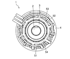
- FIG. 1A is a plan view of a motor to which a coil mounting structure according to an embodiment is applied.
- FIG. 1B is a side view of a motor to which the coil mounting structure according to the embodiment is applied.
- FIG. 1C is a sectional view taken along the line IC-IC in FIG. 1B.
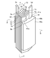
- FIG. 2 is a perspective view showing a state in which the coil is attached to the split core.
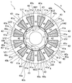
- FIG. 3 is a plan view of FIG.
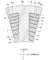
- FIG. 4 is a sectional view taken along line IV-IV in FIG.
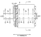
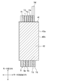
- FIG. 5 is a sectional view taken along line VV of FIG.
- the motor 1 includes a shaft 2, a rotor 3, a stator 4, coils U11 to W41, and bus bars 51 to 54 inside a cover case (not shown).
- the direction perpendicular to the paper surface is the motor rotation axis direction.
- integral or “integrated” means not only that multiple parts are mechanically connected by bolting, caulking, etc., but also by material bonding such as covalent bonding, ionic bonding, and metal bonding.
- material bonding such as covalent bonding, ionic bonding, and metal bonding.
- the shaft 2 has a hollow portion 2a inside which extends in the motor rotation axis direction, and a plurality of through holes 2b are provided on the side surface.
- the hollow portion 2a is a passage of the coolant C for cooling the inside of the motor 1, and the coolant C flows in the hollow portion 2a along the motor rotation axis direction (longitudinal direction of the shaft 2). It circulates and flows.
- a part of the refrigerant C flowing through the hollow portion 2a flows out from the plurality of through holes 2b, and also flows from the center side of the motor 1 to the outside, that is, in the direction from the rotor 3 to the stator 4, and thus the rotor 3 and the stator 4. To cool.
- the rotor 3 is provided in contact with the outer circumference of the shaft 2, and includes magnets 31, 31 ... Which face the stator 4 and whose N poles and S poles are alternately arranged along the outer circumferential direction of the shaft 2. .
- the neodymium magnet is used as the magnet 31 used in the rotor 3, but the material, shape and material of the magnet 31 may be appropriately changed according to the output of the motor 1.
- the stator 4 includes a stator core 40 composed of twelve (plural) split cores 40a shown in FIGS.
- the split core 40a includes a plate-shaped split yoke portion 40b that is curved in an arc shape around the motor rotation axis.
- a tooth portion 42 is provided on the inner peripheral surface of each split yoke portion 40 b so as to project toward the center of rotation of the motor 1 over the entire motor rotation axis direction.
- the motor rotation circumferential direction is referred to as the motor rotation circumferential direction.
- the part of the tooth part 42 excluding the tip part has a columnar shape with a rectangular cross section and extends, while the tip part of the tooth part 42 projects to both sides in the motor rotation circumferential direction.
- a portion of the tooth portion 42 excluding the tip end portion has a pair of surfaces constituting the outer peripheral surface thereof oriented in the motor rotation axis direction, and the other pair of surfaces oriented in the motor rotation circumferential direction.
- the split cores 40a are connected to each other by fitting a ring-shaped holding member 44 on the outer peripheral side of the split yoke portion 40b.
- the split yoke portions 40b of the split cores 40a form a substantially annular yoke portion 41.
- the tooth portions 42 are arranged at equal intervals on the inner peripheral surface of the yoke portion 41.
- the outer peripheral surface of the yoke portion 41 is curved so as to form a circular shape in a plan view, while the area of the inner peripheral surface of the yoke portion 41 excluding the protruding portions of the teeth portions 42 is the outer peripheral surface of the yoke portion 41 in a plan view. Is curved to form a concentric circle. Therefore, in the adjoining regions of the inner peripheral surface of the yoke portion 41, which are adjacent to the protruding portions of the teeth portion 42 on both sides in the motor rotation circumferential direction, the teeth portions 42 project from the protruding portions of the teeth portion 42 in the motor rotation circumferential direction.
- a slope 41a is formed so as to curve in the direction. Slots 43, 43 ... Are provided between the tooth portions 42, 42.
- the stator 4 is arranged outside the rotor 3 with a certain distance from the rotor 3 when viewed from the direction of the motor rotation axis.
- the teeth portion 42 of the stator core 40 is configured by a laminated body formed by laminating a plurality of core sheets made of an electromagnetic steel sheet containing silicon or the like in the motor rotation axis direction (direction orthogonal to the extending direction of the teeth portion 42). There is.
- the number of magnetic poles of the rotor 3 is 10 in total including 5 N poles and 5 S poles facing the stator 4, and the number of slots 43 is 12.
- the present invention is not limited to this, and can be applied to other combinations of the number of magnetic poles and the number of slots.
- the stator 4 has twelve coils U11 to W41, and these coils U11 to W41 are attached to the teeth portions 42, 42 ...
- the motor rotation is performed. Seen from the axial direction, they are arranged in the respective slots 43, 43 ... That is, the coils U11 to W41 are concentratedly wound around the tooth portions 42, 42 ... Further, the coils U11 to U41 are integrated with the bus bar 51, the coils V12 to V42 are integrated with the bus bar 52, and the coils W11 to W41 are integrated with the bus bar 53, respectively.
- the first character represents each phase of the motor 1 (in the present embodiment, the U phase, V phase, W phase), and the second character is the same phase.
- the third character represents the winding direction of the coil, and in this embodiment, 1 is the clockwise direction and 2 is the counterclockwise direction.
- the coil U11 represents that the U-phase is the first coil in the arrangement order and the winding direction is the clockwise direction
- the coil V42 is the fourth coil in the V-phase arrangement order and the winding direction.
- the clockwise direction means a clockwise direction when viewed from the center of the motor 1
- the "counterclockwise direction” means a counterclockwise direction when viewed from the center of the motor 1.
- the coils U11 and U41 are U-phase coils, and the coils U22 and U32 are U-bar phase coils (the direction of the magnetic field generated is opposite to that of the U-phase coil), but in the following description, Unless otherwise specified, they are collectively referred to as U-phase coils.
- the coils V12 to V42 and the coils W11 to W41 are collectively referred to as a V-phase coil and a W-phase coil, respectively.
- the coils U11 to W41 are referred to as the coil 5, respectively.
- the coil 5 includes a wound conductive wire 5a, an insulating film 5b provided on the surface of the conductive wire 5a, a lead-out portion 5c drawn from a first turn T1 (described later) of the conductive wire 5a, and a sixth turn T6 (described later). And a pull-out portion 5d pulled out from.
- the conducting wire 5a is formed by bending a plate-shaped conducting wire having a quadrangular cross section and extending in a strip shape in the width direction and winding it in a single layer for 6 turns, and is laminated in the winding axis direction from the first to sixth turns T1 to T6. It consists of a turn sequence.
- the portion wound from the tip of the pull-out portion 5c to below the position where the pull-out portion 5d is provided is referred to as a first turn T1, and the subsequent portions wound one turn at a time are sequentially arranged in the second to sixth turns T2.
- Count as ⁇ T6. Further, how to obtain the starting point of each of the turns T1 to T6 can be arbitrarily determined.
- first to sixth turns T1 to T6 are gradually thickened in the protruding direction of the teeth portion 42.
- the conducting wire 5a extending in the motor rotation circumferential direction on both sides of the teeth portion 42 in the motor rotation axis direction is rotated in the clockwise direction in FIG. 1C (the direction indicated by the arrow X in FIGS. )
- a bent portion 5e that bends in the thickness direction of the conducting wire 5a is formed near the side end portion (corner portion) so as to overlap in the winding axis direction over the entire width direction of the conducting wire 5a.
- the conducting wires 5a on both sides of the motor 5e in the circumferential direction of the motor are inclined so as to extend in the protruding direction of the teeth portion 42 as they are separated from the bent portion 5e in the circumferential direction of the motor rotation.
- An angle ⁇ formed by the conductors 5a on both sides of the bent portion 5e in the motor circumferential direction with respect to the protruding direction of the tooth portion 42 is set to an acute angle. Therefore, the conductors 5a on both sides of the bent portion 5e in the motor circumferential direction are along the inclined surface portion 41a of the yoke portion 41.
- the conducting wire 5a is made of, for example, copper, aluminum, zinc, magnesium, brass, iron, SUS or the like.
- the conductive wire 5a can be manufactured, for example, by punching the conductive wire 5a from a sheet metal every half turn and joining them by welding or the like.
- the insulating film 5b is provided on the entire surface of the conducting wire 5a except for the lead-out portions 5c and 5d so as to insulate the coil 5 from an external member (not shown).
- the coil 5 and the stator core 40 are insulated from each other by the insulating film 5b and an insulating member (not shown) such as resin or insulating paper.
- the adjacent turns of the coil 5 are insulated by the insulating film 5b.
- the insulating film 5b is made of, for example, polyimide, nylon, PEEK, acrylic, amide imide, ester imide, enamel, heat resistant resin, or the like.
- the thickness of the insulating film 5b is about several tens of ⁇ m, for example, 10 ⁇ m to 50 ⁇ m.
- the lead-out portions 5c and 5d are both a part of the conducting wire 5a, and in order to receive a current supply from the outside or to supply a current to the outside, a side surface of the coil 5, in other words, a turn string of the conducting wire 5a. It extends outward from the intersecting planes. Further, the insulating film 5b is removed from the lead-out portions 5c and 5d in order to connect with external members, for example, any of the bus bars 51 to 54 shown in FIGS. 1A and 1B. The insulating film 5b does not have to be removed in the entire area of the lead-out portions 5c and 5d, and for example, the insulating film 5b may be removed only in the portions necessary for connection with the bus bars 51 to 54.
- the inclined surface portion 41a is provided in the adjacent portion that is adjacent to the tooth portion 42 on the inner peripheral surface of the yoke portion 41 from both sides in the motor rotation circumferential direction, the adjacent portion is formed in the tooth portion 42.
- the thickness of the yoke portion 41 in the motor radial direction at the end portion on the protruding portion side of the teeth portion 42 in the adjacent region is set to prevent magnetic saturation. It can be set to a value close to the minimum required thickness. Therefore, miniaturization of the motor 1 can be realized.
- the conductors 5a on both sides in the motor circumferential direction of the bent portion 5e in the first to sixth turns T1 to T6 of the coil 5 are directed toward the protruding direction of the teeth portion 42 as the conductor 5a is separated from the bent portion 5e in the motor rotation circumferential direction. Since the coils 5 are inclined, the coil 5 is configured such that the plate surface of the conductor 5a of each of the turns T1 to T6 is perpendicular to the protruding direction of the teeth portion 42 without increasing the outer dimension of the coil 5 in the motor rotation circumferential direction.
- the area of the plate surface of the conducting wire 5a in each of the turns T1 to T6 can be increased as compared with the case where 5 is provided.
- the conductors 5a on both sides in the motor circumferential direction of the bent portion 5e in the first to sixth turns T1 to T6 of the coil 5 are directed toward the protruding direction of the teeth portion 42 as the conductor 5a is separated from the bent portion 5e in the motor rotation circumferential direction. Since the coils 5 are arranged so as to be inclined so that the plate surface of the conducting wire 5a of each of the turns T1 to T6 is perpendicular to the protruding direction of the teeth portion 42, the inner peripheral surface of the yoke portion 41 The dead space formed with the coil 5 can be narrowed. Therefore, the heat dissipation efficiency of the coil 5 can be improved, the space factor of the coil 5 in the stator 4 can be improved, and the efficiency of the motor 1 can be increased.
- the diameter of the motor 1 can be reduced by reducing the coil 5 and the tooth portion 42 in the protruding direction of the tooth portion 42. Can be miniaturized in any direction.
- the inclined surface portion 41a of the yoke portion 41 is a curved surface that curves toward the protruding direction of the tooth portion 42 as it is separated from the protruding portion of the tooth portion 42 in the motor rotation circumferential direction.
- a flat surface which is not curved and is inclined may be used.
- the angle ⁇ formed by the inclined surface portion 41a with respect to the protruding direction of the tooth portion 42 is set to an acute angle.
- the number of turns (n) of the coil 5 is set to 6, but if the number of turns is 2 or more, the number of turns (integer) other than 6 may be used.
- the conducting wire 5a of the coil 5 is formed of a wire material having a quadrangular cross section, but it may be formed of a wire material having a trapezoidal or rhombic cross section.
- the coil mounting structure according to the present disclosure can realize downsizing of a motor and is useful when applied to a motor, a power device, and the like.
Landscapes
- Engineering & Computer Science (AREA)
- Power Engineering (AREA)
- Iron Core Of Rotating Electric Machines (AREA)
- Insulation, Fastening Of Motor, Generator Windings (AREA)
- Windings For Motors And Generators (AREA)
Abstract
A tilted surface portion (41a), which curves toward the projecting direction of a tooth portion (42) as departing in the motor rotation circumferential direction from an area where the tooth portion (42) is projected in the inner circumferential surface of a yoke portion (41), is formed in an adjacent region lying adjacent from both sides in the motor rotation circumferential direction to the area where the tooth portion (42) is projected. Meanwhile, in the conducting wire (5a) of first to sixth turns (T1-T6) extending in the motor rotation circumferential direction on both sides of the tooth portion (42) in the motor rotation axis direction, bent portions (5e) bent in the thickness direction of the conducting wire (5a) are formed so as to be overlapped with each other in the winding axis direction all over the conducting wire (5a) in the width direction. The conducting wire (5a) on both sides of the bent portions (5e) in the motor circumferential direction is tilted toward the projection direction of the tooth portion (42) as departing from the bent portions (5e) in the motor rotation circumferential direction.
Description
本発明は、モータのステータの環状のヨーク部の内周面に突設された柱状のティース部と、帯状に延びる板状の導線を幅方向に屈曲させて巻回させた形状で巻回軸方向に積層した第1~第nターン(nは2以上の整数)を有し、前記ティース部に装着されたコイルとを備えたコイルの装着構造に関する。
The present invention relates to a winding shaft having a shape in which a columnar tooth portion projectingly provided on an inner peripheral surface of an annular yoke portion of a stator of a motor and a plate-shaped conductive wire extending in a band shape are bent in the width direction and wound. The present invention relates to a coil mounting structure having first to n-th turns (n is an integer of 2 or more) stacked in the direction, and a coil mounted on the teeth portion.
特許文献1には帯状に延びる板状の導線を幅方向に屈曲させて巻回させた形状で巻回軸方向に積層した第1~第nターン(nは2以上の整数)を有するコイルが開示されている。このコイルの各ターンを構成する導線は、略平坦に形成されている。
Patent Document 1 discloses a coil having first to n-th turns (n is an integer of 2 or more) laminated in the winding axis direction in a shape in which a plate-shaped conductor wire extending in a band shape is bent in the width direction and wound. It is disclosed. The conducting wire forming each turn of this coil is formed substantially flat.
ところで、モータのステータの環状のヨーク部の内周面に突設された柱状のティース部に、特許文献1のようなコイルを装着する場合に、ヨーク部の内周面におけるティース部突設箇所にモータ回転周方向両側から隣接する隣接領域を、ティース部突出方向に対して垂直な平坦面とすることが考えられる。このようにした場合、ヨーク部の外周面は通常、平面視円形をなすように湾曲しているので、ヨーク部のモータ径方向の厚さがティース部突設箇所からモータ回転周方向に離れるにつれて徐々に薄くなる。したがって、ヨーク部全体のモータ径方向の厚さを、磁気飽和を防止するための必要最低限の厚さ以上とするには、隣接領域のティース部突設箇所側の端部において、ヨーク部のモータ径方向の厚さを、前記必要最低限の厚さよりも大きく設定する必要が生じ、モータの小型化を実現できない。
By the way, when a coil as in Patent Document 1 is mounted on a columnar tooth portion projecting on the inner peripheral surface of an annular yoke portion of a stator of a motor, a tooth portion protruding portion on the inner peripheral surface of the yoke portion. In addition, it is conceivable that adjacent regions that are adjacent from both sides in the motor rotation circumferential direction are flat surfaces that are perpendicular to the tooth protrusion direction. In such a case, since the outer peripheral surface of the yoke portion is usually curved so as to form a circular shape in a plan view, as the thickness of the yoke portion in the motor radial direction increases in the motor rotation circumferential direction from the tooth portion protruding portion. It gradually becomes thinner. Therefore, in order to make the thickness of the entire yoke portion in the radial direction of the motor equal to or greater than the minimum necessary thickness for preventing magnetic saturation, the yoke portion should be It is necessary to set the thickness in the radial direction of the motor to be larger than the required minimum thickness, and it is not possible to reduce the size of the motor.
本発明は、かかる点に鑑みてなされたものであり、その目的とするところは、モータの小型化を実現することにある。
The present invention has been made in view of the above points, and an object of the present invention is to realize downsizing of a motor.
上記の目的を達成するために、ここに開示する技術では、コイルの装着構造が、モータのステータの環状のヨーク部の内周面に突設された柱状のティース部と、帯状に延びる板状の導線を幅方向に屈曲させて巻回させた形状で巻回軸方向に積層した第1~第nターン(nは2以上の整数)を有し、前記ティース部に装着されたコイルとを備え、前記ヨーク部の内周面における前記ティース部突設箇所にモータ回転周方向両側から隣接する隣接領域には、該ティース部突設箇所からモータ回転周方向に離れるに従って前記ティース部の突出方向に向かうように傾斜又は湾曲する斜面部が形成され、前記コイルの第1~第nターンにおける前記ティース部のモータ回転軸方向両側でモータ回転周方向に延びる導線には、該導線の厚さ方向に折れ曲がる折曲部が導線の幅方向全体に亘って巻回軸方向に重なるように形成され、前記コイルの第1~第nターンにおける前記折曲部のモータ周方向両側の導線は、前記折曲部からモータ回転周方向に離れるに従って前記ティース部の突出方向に向かうように傾斜していることを特徴とする。
In order to achieve the above object, in the technology disclosed herein, a coil mounting structure includes a columnar tooth portion protruding from an inner peripheral surface of an annular yoke portion of a motor stator, and a plate-like extending plate-like member. And a coil attached to the teeth portion, which has first to n-th turns (n is an integer of 2 or more) stacked in the winding axis direction in a shape in which the conductor wire is bent in the width direction and wound. In the adjoining region of the inner peripheral surface of the yoke portion, which is adjacent to the tooth portion protruding portion from both sides in the motor rotation circumferential direction, the protruding direction of the tooth portion as the tooth portion protruding portion is separated from the tooth portion protruding portion in the motor rotation circumferential direction. Is formed so as to incline or curve toward the direction. The conductor wire extending in the motor rotation circumferential direction on both sides of the teeth portion in the motor rotation axis direction in the first to nth turns of the coil has a thickness direction of the conductor wire. Broken into The bent portion is formed so as to overlap in the winding axis direction over the entire width direction of the conducting wire, and the conducting wire on both sides in the motor circumferential direction of the bending portion in the first to n-th turns of the coil is the folded wire. It is characterized in that it is inclined so as to be directed in the protruding direction of the teeth portion as it is separated from the curved portion in the motor rotation circumferential direction.
本開示によれば、ヨーク部の内周面におけるティース部突設箇所にモータ回転周方向両側から隣接する隣接領域に斜面部を設けたので、当該隣接領域をティース部の突出方向に対して垂直な平坦面とした場合に比べ、隣接領域のティース部突設箇所側の端部において、ヨーク部のモータ径方向の厚さを、磁気飽和を防止するための必要最低限の厚さに近い値に設定できる。したがって、本開示は、モータの小型化を実現できる。
According to the present disclosure, since the inclined surface portion is provided in the adjoining area that is adjacent from both sides in the motor rotation circumferential direction at the protruding portion of the tooth portion on the inner peripheral surface of the yoke portion, the adjoining area is perpendicular to the protruding direction of the tooth portion. Compared to the case where a flat surface is used, the thickness of the yoke in the radial direction of the motor is closer to the minimum thickness required to prevent magnetic saturation at the end of the adjacent area where the teeth protrude. Can be set to. Therefore, the present disclosure can realize miniaturization of a motor.
以下、本発明の実施形態について図面に基づいて説明する。
Hereinafter, an embodiment of the present invention will be described with reference to the drawings.
図1A~図1Cはそれぞれ、モータ1を示す上面図、側面図、断面図である。ただし、いずれにおいても、カバーケース等は図示していない。このモータ1は、カバーケース(図示せず)の内部に、シャフト2と、ロータ3と、ステータ4と、コイルU11~W41と、バスバー51~54と、を備えている。
1A to 1C are a top view, a side view, and a cross-sectional view showing the motor 1, respectively. However, in any case, the cover case and the like are not shown. The motor 1 includes a shaft 2, a rotor 3, a stator 4, coils U11 to W41, and bus bars 51 to 54 inside a cover case (not shown).
なお、図1A及び図1Cでは、紙面に対して垂直な方向がモータ回転軸方向となっている。
Note that, in FIGS. 1A and 1C, the direction perpendicular to the paper surface is the motor rotation axis direction.
また、「一体」あるいは「一体化」とは、複数の部品が、ボルト締めや、かしめ等の機械的に接続されているだけでなく、共有結合、イオン結合、金属結合などの材料結合によって、部品が電気的に接続された1つの物体、または部品全体が溶融などによって材料結合され電気的に接続された1つの物体の状態をいう。
In addition, "integral" or "integrated" means not only that multiple parts are mechanically connected by bolting, caulking, etc., but also by material bonding such as covalent bonding, ionic bonding, and metal bonding. The state of one object in which parts are electrically connected, or the state of one object in which all parts are material-bonded by melting or the like and electrically connected.
シャフト2は、モータ回転軸方向に延びる中空部2aを内部に有しており、側面には複数の貫通孔2bが設けられている。中空部2aはモータ1の内部を冷却するための冷媒Cの通路であり、冷媒Cは中空部2a内をモータ回転軸方向(シャフト2の長手方向)に沿って流れており、モータ1の内部で循環して流れている。また、中空部2aを流れる冷媒Cの一部は複数の貫通孔2bから流れ出て、モータ1の中心側から外側、つまりロータ3からステータ4のある方向に向けても流れ、ロータ3やステータ4を冷却する。
The shaft 2 has a hollow portion 2a inside which extends in the motor rotation axis direction, and a plurality of through holes 2b are provided on the side surface. The hollow portion 2a is a passage of the coolant C for cooling the inside of the motor 1, and the coolant C flows in the hollow portion 2a along the motor rotation axis direction (longitudinal direction of the shaft 2). It circulates and flows. In addition, a part of the refrigerant C flowing through the hollow portion 2a flows out from the plurality of through holes 2b, and also flows from the center side of the motor 1 to the outside, that is, in the direction from the rotor 3 to the stator 4, and thus the rotor 3 and the stator 4. To cool.
ロータ3は、シャフト2の外周に接して設けられており、ステータ4に対向してN極、S極がシャフト2の外周方向に沿って交互に配置された磁石31,31…を含んでいる。なお、本実施形態1では、ロータ3に用いられる磁石31としてネオジム磁石を使用しているが、その材料や形状や材質については、モータ1の出力等に応じて適宜変更しうる。
The rotor 3 is provided in contact with the outer circumference of the shaft 2, and includes magnets 31, 31 ... Which face the stator 4 and whose N poles and S poles are alternately arranged along the outer circumferential direction of the shaft 2. . In the first embodiment, the neodymium magnet is used as the magnet 31 used in the rotor 3, but the material, shape and material of the magnet 31 may be appropriately changed according to the output of the motor 1.
ステータ4は、12個(複数)の図2~図5にも示す分割コア40aで構成されたステータコア40を備えている。分割コア40aは、モータ回転軸を中心とする円弧状に湾曲する板状の分割ヨーク部40bを備えている。各分割ヨーク部40bの内周面には、ティース部42が、モータ回転軸方向全体に亘ってモータ1の回転中心に向けて突設されている。以下、ティース部42の突出方向に対して垂直な2方向のうち、モータ回転軸方向に垂直な方向をモータ回転周方向と呼ぶ。ティース部42の先端部を除く部分は、断面四角形状で延在する柱形状をなしている一方、ティース部42の先端部は、モータ回転周方向両側に張り出している。ティース部42の先端部を除く部分は、その外周面を構成する1対の面をモータ回転軸方向に向けるとともに、残りの1対の面をモータ回転周方向に向けている。そして、これら分割コア40aは、分割ヨーク部40bの外周側に、リング状の保持部材44を嵌合させることにより、互いに連結されている。そして、複数の分割コア40aの分割ヨーク部40bにより、略円環状のヨーク部41が構成されている。したがって、ヨーク部41の内周面には、ティース部42が等間隔に配設されている。ヨーク部41の外周面は、平面視円形状をなすように湾曲している一方、ヨーク部41の内周面におけるティース部42突設箇所を除く領域は、平面視でヨーク部41の外周面の同心円をなすように湾曲している。したがって、ヨーク部41の内周面におけるティース部42突設箇所にモータ回転周方向両側から隣接する隣接領域には、ティース部42突設箇所からモータ回転周方向に離れるに従って前記ティース部42の突出方向に向かうように湾曲する斜面部41aが形成されている。ティース部42,42…間には、スロット43,43…がそれぞれ設けられている。ステータ4は、モータ回転軸方向から見て、ロータ3の外側に、ロータ3と一定の間隔を持って離間して配置されている。
The stator 4 includes a stator core 40 composed of twelve (plural) split cores 40a shown in FIGS. The split core 40a includes a plate-shaped split yoke portion 40b that is curved in an arc shape around the motor rotation axis. A tooth portion 42 is provided on the inner peripheral surface of each split yoke portion 40 b so as to project toward the center of rotation of the motor 1 over the entire motor rotation axis direction. Hereinafter, of the two directions perpendicular to the protruding direction of the teeth portion 42, the direction perpendicular to the motor rotation axis direction is referred to as the motor rotation circumferential direction. The part of the tooth part 42 excluding the tip part has a columnar shape with a rectangular cross section and extends, while the tip part of the tooth part 42 projects to both sides in the motor rotation circumferential direction. A portion of the tooth portion 42 excluding the tip end portion has a pair of surfaces constituting the outer peripheral surface thereof oriented in the motor rotation axis direction, and the other pair of surfaces oriented in the motor rotation circumferential direction. The split cores 40a are connected to each other by fitting a ring-shaped holding member 44 on the outer peripheral side of the split yoke portion 40b. The split yoke portions 40b of the split cores 40a form a substantially annular yoke portion 41. Therefore, the tooth portions 42 are arranged at equal intervals on the inner peripheral surface of the yoke portion 41. The outer peripheral surface of the yoke portion 41 is curved so as to form a circular shape in a plan view, while the area of the inner peripheral surface of the yoke portion 41 excluding the protruding portions of the teeth portions 42 is the outer peripheral surface of the yoke portion 41 in a plan view. Is curved to form a concentric circle. Therefore, in the adjoining regions of the inner peripheral surface of the yoke portion 41, which are adjacent to the protruding portions of the teeth portion 42 on both sides in the motor rotation circumferential direction, the teeth portions 42 project from the protruding portions of the teeth portion 42 in the motor rotation circumferential direction. A slope 41a is formed so as to curve in the direction. Slots 43, 43 ... Are provided between the tooth portions 42, 42. The stator 4 is arranged outside the rotor 3 with a certain distance from the rotor 3 when viewed from the direction of the motor rotation axis.
ステータコア40のティース部42は、ケイ素等を含有した電磁鋼板からなる複数のコアシートをモータ回転軸方向(ティース部42の延在方向と直交する方向)に積層してなる積層体で構成されている。
The teeth portion 42 of the stator core 40 is configured by a laminated body formed by laminating a plurality of core sheets made of an electromagnetic steel sheet containing silicon or the like in the motor rotation axis direction (direction orthogonal to the extending direction of the teeth portion 42). There is.
なお、本実施形態において、ロータ3の磁極数は、ステータ4に対向するN極が5個、S極が5個の計10極であり、スロット43の数は12個であるが、特にこれに限定されるものではなく、その他の磁極数とスロット数との組合せについても適用できる。
In this embodiment, the number of magnetic poles of the rotor 3 is 10 in total including 5 N poles and 5 S poles facing the stator 4, and the number of slots 43 is 12. However, the present invention is not limited to this, and can be applied to other combinations of the number of magnetic poles and the number of slots.
また、ステータ4は12個のコイルU11~W41を有しており、これらのコイルU11~W41は本実施形態に係る装着構造を適用して各ティース部42,42…に装着されて、モータ回転軸方向から見て、各スロット43,43…内に配置されている。つまり、コイルU11~W41はティース部42,42…に対して集中巻になっている。さらに、コイルU11~U41がバスバー51と、コイルV12~V42はバスバー52と、コイルW11~W41はバスバー53とそれぞれ一体化されて配置されている。
Further, the stator 4 has twelve coils U11 to W41, and these coils U11 to W41 are attached to the teeth portions 42, 42 ... By applying the attachment structure according to the present embodiment, and the motor rotation is performed. Seen from the axial direction, they are arranged in the respective slots 43, 43 ... That is, the coils U11 to W41 are concentratedly wound around the tooth portions 42, 42 ... Further, the coils U11 to U41 are integrated with the bus bar 51, the coils V12 to V42 are integrated with the bus bar 52, and the coils W11 to W41 are integrated with the bus bar 53, respectively.
ここで、コイルを表わす符号UXY、VXY、WXYのうち、最初の文字はモータ1の各相(本実施形態の場合は、U相、V相、W相)を表わし、2番目の文字は同相内のコイルの配列順を表わす。3番目の文字はコイルの巻回方向を表わし、本実施形態では、1は時計回り方向、2は反時計回り方向である。従って、コイルU11は、U相の配列順が1番目のコイルで、巻回方向が時計回り方向であることを表わし、コイルV42は、V相の配列順が4番目のコイルで、巻回方向が反時計回り方向であることを表わす。なお、時計回りとは、モータ1の中心から見て右回りをいい、「反時計回り」とはモータ1の中心から見て左回りをいう。
Here, of the symbols UXY, VXY, WXY representing the coils, the first character represents each phase of the motor 1 (in the present embodiment, the U phase, V phase, W phase), and the second character is the same phase. Represents the order of arrangement of the coils inside. The third character represents the winding direction of the coil, and in this embodiment, 1 is the clockwise direction and 2 is the counterclockwise direction. Accordingly, the coil U11 represents that the U-phase is the first coil in the arrangement order and the winding direction is the clockwise direction, and the coil V42 is the fourth coil in the V-phase arrangement order and the winding direction. Indicates that the direction is counterclockwise. The clockwise direction means a clockwise direction when viewed from the center of the motor 1, and the "counterclockwise direction" means a counterclockwise direction when viewed from the center of the motor 1.
また、厳密には、コイルU11,U41はU相のコイルであり、コイルU22,U32はUバー相(U相コイルと発生する磁界の向きが逆)のコイルであるが、以降の説明では、特に断らない限り、U相のコイルと総称する。コイルV12~V42及びコイルW11~W41についても同様に、V相のコイル、W相のコイルとそれぞれ総称する。以下、コイルU11~W41をそれぞれ、コイル5と示す。
Strictly speaking, the coils U11 and U41 are U-phase coils, and the coils U22 and U32 are U-bar phase coils (the direction of the magnetic field generated is opposite to that of the U-phase coil), but in the following description, Unless otherwise specified, they are collectively referred to as U-phase coils. Similarly, the coils V12 to V42 and the coils W11 to W41 are collectively referred to as a V-phase coil and a W-phase coil, respectively. Hereinafter, the coils U11 to W41 are referred to as the coil 5, respectively.
コイル5は、巻回された導線5aと、導線5aの表面に設けられた絶縁皮膜5bと、導線5aの第1ターンT1(後述)から引き出された引出し部5c及び第6ターンT6(後述)から引き出された引出し部5dとを有している。
The coil 5 includes a wound conductive wire 5a, an insulating film 5b provided on the surface of the conductive wire 5a, a lead-out portion 5c drawn from a first turn T1 (described later) of the conductive wire 5a, and a sixth turn T6 (described later). And a pull-out portion 5d pulled out from.
導線5aは、断面四角形状で帯状に延びる板状の導線を幅方向に屈曲させて単層で6ターン巻回させた形状で巻回軸方向に積層した第1~第6ターンT1~T6からなるターン列を構成している。なお、引出し部5cの先端から引出し部5dが設けられた位置の下方まで巻回された部分を第1ターンT1とし、以降の1周ずつ巻回された部分を順に第2~第6ターンT2~T6と数えることとする。また、各ターンT1~T6の始点の取り方は任意に定めることができる。これら第1~第6ターンT1~T6は、前記ティース部42の突出方向に向かって徐々に厚くなっている。また、第1~第6ターンT1~T6における前記ティース部42のモータ回転軸方向両側でモータ回転周方向に延びる導線5aの図1C中右回り方向(図1C及び図3において矢印Xで示す方向)側端部(コーナー部)近傍には、該導線5aの厚さ方向に折れ曲がる折曲部5eが導線5aの幅方向全体に亘って巻回軸方向に重なるように形成され、前記折曲部5eのモータ周方向両側の導線5aは、折曲部5eからモータ回転周方向に離れるに従ってティース部42の突出方向に向かうように傾斜している。ティース部42の突出方向に対して折曲部5eのモータ周方向両側の導線5aがなす角度αは、鋭角に設定されている。したがって、折曲部5eのモータ周方向両側の導線5aは、前記ヨーク部41の斜面部41aに沿っている。導線5aは、例えば、銅、アルミニウム、亜鉛、マグネシウム、真鍮、鉄、SUS等によって形成されている。導線5aは、例えば、導線5aを半ターン分毎に板金から打ち抜いて溶接等により互いに接合することにより製造できる。
The conducting wire 5a is formed by bending a plate-shaped conducting wire having a quadrangular cross section and extending in a strip shape in the width direction and winding it in a single layer for 6 turns, and is laminated in the winding axis direction from the first to sixth turns T1 to T6. It consists of a turn sequence. The portion wound from the tip of the pull-out portion 5c to below the position where the pull-out portion 5d is provided is referred to as a first turn T1, and the subsequent portions wound one turn at a time are sequentially arranged in the second to sixth turns T2. Count as ~ T6. Further, how to obtain the starting point of each of the turns T1 to T6 can be arbitrarily determined. These first to sixth turns T1 to T6 are gradually thickened in the protruding direction of the teeth portion 42. In addition, in the first to sixth turns T1 to T6, the conducting wire 5a extending in the motor rotation circumferential direction on both sides of the teeth portion 42 in the motor rotation axis direction is rotated in the clockwise direction in FIG. 1C (the direction indicated by the arrow X in FIGS. ) A bent portion 5e that bends in the thickness direction of the conducting wire 5a is formed near the side end portion (corner portion) so as to overlap in the winding axis direction over the entire width direction of the conducting wire 5a. The conducting wires 5a on both sides of the motor 5e in the circumferential direction of the motor are inclined so as to extend in the protruding direction of the teeth portion 42 as they are separated from the bent portion 5e in the circumferential direction of the motor rotation. An angle α formed by the conductors 5a on both sides of the bent portion 5e in the motor circumferential direction with respect to the protruding direction of the tooth portion 42 is set to an acute angle. Therefore, the conductors 5a on both sides of the bent portion 5e in the motor circumferential direction are along the inclined surface portion 41a of the yoke portion 41. The conducting wire 5a is made of, for example, copper, aluminum, zinc, magnesium, brass, iron, SUS or the like. The conductive wire 5a can be manufactured, for example, by punching the conductive wire 5a from a sheet metal every half turn and joining them by welding or the like.
絶縁皮膜5bは、コイル5と外部の部材(図示せず)を絶縁するように、導線5aの引出し部5c,5dを除く表面全体に設けられている。例えば、図1A~図1Cに示すモータ1において、絶縁皮膜5b及び図示しない絶縁部材、例えば樹脂、絶縁紙等によって、コイル5とステータコア40との間が絶縁される。また、コイル5における隣接するターン間は絶縁皮膜5bによって絶縁されている。絶縁皮膜5bは、例えば、ポリイミド、ナイロン、PEEK、アクリル、アミドイミド、エステルイミド、エナメル、耐熱樹脂等によって形成されている。絶縁皮膜5bの厚みは、数十μm程度、例えば、10μmから50μmの間である。
The insulating film 5b is provided on the entire surface of the conducting wire 5a except for the lead-out portions 5c and 5d so as to insulate the coil 5 from an external member (not shown). For example, in the motor 1 shown in FIGS. 1A to 1C, the coil 5 and the stator core 40 are insulated from each other by the insulating film 5b and an insulating member (not shown) such as resin or insulating paper. The adjacent turns of the coil 5 are insulated by the insulating film 5b. The insulating film 5b is made of, for example, polyimide, nylon, PEEK, acrylic, amide imide, ester imide, enamel, heat resistant resin, or the like. The thickness of the insulating film 5b is about several tens of μm, for example, 10 μm to 50 μm.
引出し部5c,5dはいずれも導線5aの一部であり、外部からの電流供給を受けるため、あるいは外部に電流を供給するために、コイル5の側面、言いかえると、導線5aのターン列と交差する平面から外側に延在している。また、外部の部材、例えば、図1A,図1Bに示すバスバー51~54のいずれかと接続するために、引出し部5c,5dにおいて、絶縁皮膜5bが除去されている。なお、絶縁皮膜5bは、引出し部5c,5dの全領域で除去されている必要はなく、例えば、バスバー51~54との接続に必要な部分のみ絶縁皮膜5bが除去されていればよい。
The lead-out portions 5c and 5d are both a part of the conducting wire 5a, and in order to receive a current supply from the outside or to supply a current to the outside, a side surface of the coil 5, in other words, a turn string of the conducting wire 5a. It extends outward from the intersecting planes. Further, the insulating film 5b is removed from the lead-out portions 5c and 5d in order to connect with external members, for example, any of the bus bars 51 to 54 shown in FIGS. 1A and 1B. The insulating film 5b does not have to be removed in the entire area of the lead-out portions 5c and 5d, and for example, the insulating film 5b may be removed only in the portions necessary for connection with the bus bars 51 to 54.
したがって、本実施形態によれば、ヨーク部41の内周面におけるティース部42突設箇所にモータ回転周方向両側から隣接する隣接領域に斜面部41aを設けたので、当該隣接領域をティース部42の突出方向に対して垂直な平坦面とした場合に比べ、隣接領域のティース部42突設箇所側の端部において、ヨーク部41のモータ径方向の厚さを、磁気飽和を防止するための必要最低限の厚さに近い値に設定できる。したがって、モータ1の小型化を実現できる。
Therefore, according to the present embodiment, since the inclined surface portion 41a is provided in the adjacent portion that is adjacent to the tooth portion 42 on the inner peripheral surface of the yoke portion 41 from both sides in the motor rotation circumferential direction, the adjacent portion is formed in the tooth portion 42. In comparison with the case where a flat surface is formed perpendicular to the protruding direction, the thickness of the yoke portion 41 in the motor radial direction at the end portion on the protruding portion side of the teeth portion 42 in the adjacent region is set to prevent magnetic saturation. It can be set to a value close to the minimum required thickness. Therefore, miniaturization of the motor 1 can be realized.
また、コイル5の第1~第6ターンT1~T6における折曲部5eのモータ周方向両側の導線5aを折曲部5eからモータ回転周方向に離れるに従ってティース部42の突出方向に向かうように傾斜させているので、コイル5外形のモータ回転周方向の寸法を大きくしなくても、各ターンT1~T6の導線5aの板面がティース部42の突出方向に対して垂直となるようにコイル5を配設した場合に比べ、各ターンT1~T6の導線5aの板面の面積を増大できる。
Further, the conductors 5a on both sides in the motor circumferential direction of the bent portion 5e in the first to sixth turns T1 to T6 of the coil 5 are directed toward the protruding direction of the teeth portion 42 as the conductor 5a is separated from the bent portion 5e in the motor rotation circumferential direction. Since the coils 5 are inclined, the coil 5 is configured such that the plate surface of the conductor 5a of each of the turns T1 to T6 is perpendicular to the protruding direction of the teeth portion 42 without increasing the outer dimension of the coil 5 in the motor rotation circumferential direction. The area of the plate surface of the conducting wire 5a in each of the turns T1 to T6 can be increased as compared with the case where 5 is provided.
また、コイル5の第1~第6ターンT1~T6における折曲部5eのモータ周方向両側の導線5aを折曲部5eからモータ回転周方向に離れるに従ってティース部42の突出方向に向かうように傾斜させているので、各ターンT1~T6の導線5aの板面がティース部42の突出方向に対して垂直となるようにコイル5を配設した場合に比べ、ヨーク部41の内周面とコイル5との間に形成されるデッドスペースを狭くできる。したがって、コイル5の放熱効率を高め、ステータ4内でのコイル5の占積率を向上し、モータ1の効率を高めることができる。
Further, the conductors 5a on both sides in the motor circumferential direction of the bent portion 5e in the first to sixth turns T1 to T6 of the coil 5 are directed toward the protruding direction of the teeth portion 42 as the conductor 5a is separated from the bent portion 5e in the motor rotation circumferential direction. Since the coils 5 are arranged so as to be inclined so that the plate surface of the conducting wire 5a of each of the turns T1 to T6 is perpendicular to the protruding direction of the teeth portion 42, the inner peripheral surface of the yoke portion 41 The dead space formed with the coil 5 can be narrowed. Therefore, the heat dissipation efficiency of the coil 5 can be improved, the space factor of the coil 5 in the stator 4 can be improved, and the efficiency of the motor 1 can be increased.
また、ヨーク部41の内周面とコイル5との間に形成されるデッドスペースを減らせるので、コイル5及びティース部42をティース部42の突出方向に小さくすることにより、モータ1をその径方向に小型化できる。
Further, since the dead space formed between the inner peripheral surface of the yoke portion 41 and the coil 5 can be reduced, the diameter of the motor 1 can be reduced by reducing the coil 5 and the tooth portion 42 in the protruding direction of the tooth portion 42. Can be miniaturized in any direction.
なお、上記実施形態では、ヨーク部41の斜面部41aを、ティース部42突設箇所からモータ回転周方向に離れるに従って前記ティース部42の突出方向に向かうように湾曲する湾曲面としたが、図4中、仮想線で示すように、湾曲せず傾斜する平坦面としてもよい。かかる場合、ティース部42の突出方向に対して斜面部41aがなす角度βは、鋭角に設定される。
In the above-described embodiment, the inclined surface portion 41a of the yoke portion 41 is a curved surface that curves toward the protruding direction of the tooth portion 42 as it is separated from the protruding portion of the tooth portion 42 in the motor rotation circumferential direction. Among them, as shown by an imaginary line, a flat surface which is not curved and is inclined may be used. In this case, the angle β formed by the inclined surface portion 41a with respect to the protruding direction of the tooth portion 42 is set to an acute angle.
また、上記実施形態では、コイル5のターン数(n)を6としたが、2以上であれば、6以外のターン数(整数)としてもよい。
In the above embodiment, the number of turns (n) of the coil 5 is set to 6, but if the number of turns is 2 or more, the number of turns (integer) other than 6 may be used.
また、上記実施形態では、コイル5の導線5aを、断面が四角形状の線材で構成したが、断面が台形又は菱形形状の線材で構成してもよい。
In addition, in the above embodiment, the conducting wire 5a of the coil 5 is formed of a wire material having a quadrangular cross section, but it may be formed of a wire material having a trapezoidal or rhombic cross section.
本開示に係るコイルの装着構造は、モータの小型化を実現することができ、モータ、電力機器等に適用する上で有用である。
The coil mounting structure according to the present disclosure can realize downsizing of a motor and is useful when applied to a motor, a power device, and the like.
1 モータ
4 ステータ
41 ヨーク部
41a 斜面部
42 ティース部
5 コイル
5a 導線
5e 折曲部
T1~T6 ターン 1Motor 4 Stator 41 Yoke 41a Slope 42 Teeth 5 Coil 5a Conductor 5e Bent T1 to T6 Turn
4 ステータ
41 ヨーク部
41a 斜面部
42 ティース部
5 コイル
5a 導線
5e 折曲部
T1~T6 ターン 1
Claims (2)
- モータのステータの環状のヨーク部の内周面に突設された柱状のティース部と、
帯状に延びる板状の導線を幅方向に屈曲させて巻回させた形状で巻回軸方向に積層した第1~第nターン(nは2以上の整数)を有し、前記ティース部に装着されたコイルとを備え、
前記ヨーク部の内周面における前記ティース部突設箇所にモータ回転周方向両側から隣接する隣接領域には、該ティース部突設箇所からモータ回転周方向に離れるに従って前記ティース部の突出方向に向かうように傾斜又は湾曲する斜面部が形成され、
前記コイルの第1~第nターンにおける前記ティース部のモータ回転軸方向両側でモータ回転周方向に延びる導線には、該導線の厚さ方向に折れ曲がる折曲部が導線の幅方向全体に亘って巻回軸方向に重なるように形成され、前記コイルの第1~第nターンにおける前記折曲部のモータ周方向両側の導線は、前記折曲部からモータ回転周方向に離れるに従って前記ティース部の突出方向に向かうように傾斜していることを特徴とするコイルの装着構造。 A columnar tooth portion protruding from the inner peripheral surface of the annular yoke portion of the motor stator,
It has a first to n-th turns (n is an integer of 2 or more) stacked in the winding axis direction in a shape in which a strip-shaped conductor wire extending in a strip shape is bent in the width direction and wound, and is attached to the teeth portion. Equipped coil and
Adjacent regions of the inner peripheral surface of the yoke portion, which are adjacent to the tooth portion projecting portions from both sides in the motor rotation circumferential direction, move in the projecting direction of the tooth portions as the tooth portion projecting portions are separated from each other in the motor rotation circumferential direction. Is formed so that the inclined surface is inclined or curved,
In the conductor wire extending in the motor rotation circumferential direction on both sides of the teeth portion in the motor rotation axis direction in the first to n-th turns of the coil, a bent portion bent in the thickness direction of the conductor wire is provided over the entire width direction of the conductor wire. Conductive wires that are formed so as to overlap in the winding axis direction and that are located on both sides of the bent portion in the motor circumferential direction in the first to n-th turns of the coil are separated from the bent portion in the motor rotation circumferential direction. A coil mounting structure characterized by being inclined so as to extend in a protruding direction. - 請求項1に記載のコイルの装着構造において、
前記コイルの第1~第nターンは、前記ティース部の突出方向に向かって徐々に厚くなっていることを特徴とするコイルの装着構造。
The coil mounting structure according to claim 1,
The coil mounting structure, wherein the first to n-th turns of the coil are gradually thickened in a protruding direction of the tooth portion.
Priority Applications (4)
| Application Number | Priority Date | Filing Date | Title |
|---|---|---|---|
| EP19872536.8A EP3869672A4 (en) | 2018-10-18 | 2019-10-17 | Coil mounting structure |
| US17/285,458 US11929654B2 (en) | 2018-10-18 | 2019-10-17 | Coil mounting structure |
| JP2020553304A JPWO2020080481A1 (en) | 2018-10-18 | 2019-10-17 | Coil mounting structure |
| CN201980068021.8A CN112868164A (en) | 2018-10-18 | 2019-10-17 | Coil mounting structure |
Applications Claiming Priority (2)
| Application Number | Priority Date | Filing Date | Title |
|---|---|---|---|
| JP2018196586 | 2018-10-18 | ||
| JP2018-196586 | 2018-10-18 |
Publications (1)
| Publication Number | Publication Date |
|---|---|
| WO2020080481A1 true WO2020080481A1 (en) | 2020-04-23 |
Family
ID=70283029
Family Applications (1)
| Application Number | Title | Priority Date | Filing Date |
|---|---|---|---|
| PCT/JP2019/040950 WO2020080481A1 (en) | 2018-10-18 | 2019-10-17 | Coil mounting structure |
Country Status (5)
| Country | Link |
|---|---|
| US (1) | US11929654B2 (en) |
| EP (1) | EP3869672A4 (en) |
| JP (1) | JPWO2020080481A1 (en) |
| CN (1) | CN112868164A (en) |
| WO (1) | WO2020080481A1 (en) |
Cited By (1)
| Publication number | Priority date | Publication date | Assignee | Title |
|---|---|---|---|---|
| EP4203244A4 (en) * | 2020-08-27 | 2024-05-22 | IHI Corporation | Stator |
Families Citing this family (1)
| Publication number | Priority date | Publication date | Assignee | Title |
|---|---|---|---|---|
| CN112913122B (en) * | 2018-10-18 | 2024-07-12 | 松下知识产权经营株式会社 | Coil device |
Citations (6)
| Publication number | Priority date | Publication date | Assignee | Title |
|---|---|---|---|---|
| JPS5379201A (en) * | 1976-12-23 | 1978-07-13 | Toshiba Corp | Manufacturing for interpole windings |
| JP2004261000A (en) * | 2004-06-21 | 2004-09-16 | Hitachi Ltd | Stator of rotary electric machine |
| JP2005186092A (en) * | 2003-12-25 | 2005-07-14 | Sumitomo Electric Ind Ltd | Method for manufacturing coil of dissimilar section, and method for assembling coil of dissimilar section |
| JP2006014530A (en) * | 2004-06-28 | 2006-01-12 | Sumitomo Electric Ind Ltd | Coil and its manufacturing method |
| DE102012212637A1 (en) | 2012-07-18 | 2014-01-23 | Fraunhofer-Gesellschaft zur Förderung der angewandten Forschung e.V. | Casting electrical coil |
| JP2015042113A (en) * | 2013-08-23 | 2015-03-02 | 三菱電機株式会社 | Stator and motor |
Family Cites Families (10)
| Publication number | Priority date | Publication date | Assignee | Title |
|---|---|---|---|---|
| CN102655363B (en) * | 2011-03-02 | 2014-11-26 | 株式会社丰田自动织机 | Rotary electric machine |
| JP2013135587A (en) * | 2011-12-27 | 2013-07-08 | Daikin Ind Ltd | Stator, motor, compressor, and coil winding method |
| US9502931B2 (en) * | 2012-03-23 | 2016-11-22 | Asmo Co., Ltd. | Brushless motor |
| DE102012222318A1 (en) * | 2012-12-05 | 2014-06-05 | Robert Bosch Gmbh | Toothed segment coil combination for an electric machine |
| JP6196804B2 (en) * | 2013-05-16 | 2017-09-13 | 株式会社Subaru | Rotating electric machine stator |
| DE112014006070B4 (en) * | 2013-12-25 | 2018-09-20 | Mitsubishi Electric Corporation | Electric motor with magnetic inductor and associated manufacturing process |
| JP2016067100A (en) * | 2014-09-24 | 2016-04-28 | ダイキン工業株式会社 | Motor, compressor, and method of manufacturing motor |
| JP6578516B2 (en) * | 2014-09-26 | 2019-09-25 | パナソニックIpマネジメント株式会社 | Induction motor |
| JP2016082683A (en) * | 2014-10-15 | 2016-05-16 | トヨタ自動車株式会社 | Stator for rotary electric machine |
| CN107925299B (en) * | 2015-09-28 | 2019-12-10 | 日本电产株式会社 | stator, motor, disk drive device, and method for manufacturing stator |
-
2019
- 2019-10-17 EP EP19872536.8A patent/EP3869672A4/en active Pending
- 2019-10-17 WO PCT/JP2019/040950 patent/WO2020080481A1/en unknown
- 2019-10-17 CN CN201980068021.8A patent/CN112868164A/en not_active Withdrawn
- 2019-10-17 US US17/285,458 patent/US11929654B2/en active Active
- 2019-10-17 JP JP2020553304A patent/JPWO2020080481A1/en active Pending
Patent Citations (6)
| Publication number | Priority date | Publication date | Assignee | Title |
|---|---|---|---|---|
| JPS5379201A (en) * | 1976-12-23 | 1978-07-13 | Toshiba Corp | Manufacturing for interpole windings |
| JP2005186092A (en) * | 2003-12-25 | 2005-07-14 | Sumitomo Electric Ind Ltd | Method for manufacturing coil of dissimilar section, and method for assembling coil of dissimilar section |
| JP2004261000A (en) * | 2004-06-21 | 2004-09-16 | Hitachi Ltd | Stator of rotary electric machine |
| JP2006014530A (en) * | 2004-06-28 | 2006-01-12 | Sumitomo Electric Ind Ltd | Coil and its manufacturing method |
| DE102012212637A1 (en) | 2012-07-18 | 2014-01-23 | Fraunhofer-Gesellschaft zur Förderung der angewandten Forschung e.V. | Casting electrical coil |
| JP2015042113A (en) * | 2013-08-23 | 2015-03-02 | 三菱電機株式会社 | Stator and motor |
Non-Patent Citations (1)
| Title |
|---|
| See also references of EP3869672A4 |
Cited By (1)
| Publication number | Priority date | Publication date | Assignee | Title |
|---|---|---|---|---|
| EP4203244A4 (en) * | 2020-08-27 | 2024-05-22 | IHI Corporation | Stator |
Also Published As
| Publication number | Publication date |
|---|---|
| US20210344246A1 (en) | 2021-11-04 |
| CN112868164A (en) | 2021-05-28 |
| EP3869672A4 (en) | 2021-12-08 |
| EP3869672A1 (en) | 2021-08-25 |
| US11929654B2 (en) | 2024-03-12 |
| JPWO2020080481A1 (en) | 2021-09-09 |
Similar Documents
| Publication | Publication Date | Title |
|---|---|---|
| JP7016001B2 (en) | Assembling method of coil molded body, its manufacturing method, motor, and stator | |
| CN111971763B (en) | Coil and motor using the same | |
| JP6432016B2 (en) | Rotating electrical machine | |
| WO2020017143A1 (en) | Motor | |
| WO2020080481A1 (en) | Coil mounting structure | |
| EP3611826B1 (en) | Coil and motor using same | |
| US20120019085A1 (en) | Rotary electric machine armature | |
| JP7050234B2 (en) | motor | |
| WO2020026792A1 (en) | Motor | |
| JP7445926B2 (en) | coil device | |
| JP7386399B2 (en) | Coil installation structure, stator and motor | |
| US10720799B2 (en) | Stator of rotary electric machine | |
| WO2021095343A1 (en) | Motor | |
| JPWO2021095343A5 (en) | ||
| WO2022259453A1 (en) | Electric motor, blower, and air conditioning device | |
| JP7066539B2 (en) | Rotating electric machine |
Legal Events
| Date | Code | Title | Description |
|---|---|---|---|
| 121 | Ep: the epo has been informed by wipo that ep was designated in this application |
Ref document number: 19872536 Country of ref document: EP Kind code of ref document: A1 |
|
| ENP | Entry into the national phase |
Ref document number: 2020553304 Country of ref document: JP Kind code of ref document: A |
|
| NENP | Non-entry into the national phase |
Ref country code: DE |
|
| ENP | Entry into the national phase |
Ref document number: 2019872536 Country of ref document: EP Effective date: 20210518 |