WO2020080237A1 - センサの校正システム、表示制御装置、プログラム、およびセンサの校正方法 - Google Patents
センサの校正システム、表示制御装置、プログラム、およびセンサの校正方法 Download PDFInfo
- Publication number
- WO2020080237A1 WO2020080237A1 PCT/JP2019/039932 JP2019039932W WO2020080237A1 WO 2020080237 A1 WO2020080237 A1 WO 2020080237A1 JP 2019039932 W JP2019039932 W JP 2019039932W WO 2020080237 A1 WO2020080237 A1 WO 2020080237A1
- Authority
- WO
- WIPO (PCT)
- Prior art keywords
- calibration pattern
- sensor
- brightness
- calibration
- region
- Prior art date
- Legal status (The legal status is an assumption and is not a legal conclusion. Google has not performed a legal analysis and makes no representation as to the accuracy of the status listed.)
- Ceased
Links
Images


Classifications
-
- H—ELECTRICITY
- H04—ELECTRIC COMMUNICATION TECHNIQUE
- H04N—PICTORIAL COMMUNICATION, e.g. TELEVISION
- H04N17/00—Diagnosis, testing or measuring for television systems or their details
- H04N17/002—Diagnosis, testing or measuring for television systems or their details for television cameras
-
- H—ELECTRICITY
- H04—ELECTRIC COMMUNICATION TECHNIQUE
- H04N—PICTORIAL COMMUNICATION, e.g. TELEVISION
- H04N25/00—Circuitry of solid-state image sensors [SSIS]; Control thereof
- H04N25/40—Extracting pixel data from image sensors by controlling scanning circuits, e.g. by modifying the number of pixels sampled or to be sampled
- H04N25/42—Extracting pixel data from image sensors by controlling scanning circuits, e.g. by modifying the number of pixels sampled or to be sampled by switching between different modes of operation using different resolutions or aspect ratios, e.g. switching between interlaced and non-interlaced mode
-
- G—PHYSICS
- G01—MEASURING; TESTING
- G01M—TESTING STATIC OR DYNAMIC BALANCE OF MACHINES OR STRUCTURES; TESTING OF STRUCTURES OR APPARATUS, NOT OTHERWISE PROVIDED FOR
- G01M11/00—Testing of optical apparatus; Testing structures by optical methods not otherwise provided for
- G01M11/02—Testing optical properties
- G01M11/0242—Testing optical properties by measuring geometrical properties or aberrations
- G01M11/0257—Testing optical properties by measuring geometrical properties or aberrations by analyzing the image formed by the object to be tested
- G01M11/0264—Testing optical properties by measuring geometrical properties or aberrations by analyzing the image formed by the object to be tested by using targets or reference patterns
-
- G—PHYSICS
- G06—COMPUTING OR CALCULATING; COUNTING
- G06T—IMAGE DATA PROCESSING OR GENERATION, IN GENERAL
- G06T7/00—Image analysis
- G06T7/80—Analysis of captured images to determine intrinsic or extrinsic camera parameters, i.e. camera calibration
-
- H—ELECTRICITY
- H04—ELECTRIC COMMUNICATION TECHNIQUE
- H04N—PICTORIAL COMMUNICATION, e.g. TELEVISION
- H04N25/00—Circuitry of solid-state image sensors [SSIS]; Control thereof
- H04N25/47—Image sensors with pixel address output; Event-driven image sensors; Selection of pixels to be read out based on image data
-
- H—ELECTRICITY
- H04—ELECTRIC COMMUNICATION TECHNIQUE
- H04N—PICTORIAL COMMUNICATION, e.g. TELEVISION
- H04N25/00—Circuitry of solid-state image sensors [SSIS]; Control thereof
- H04N25/60—Noise processing, e.g. detecting, correcting, reducing or removing noise
- H04N25/68—Noise processing, e.g. detecting, correcting, reducing or removing noise applied to defects
-
- H—ELECTRICITY
- H04—ELECTRIC COMMUNICATION TECHNIQUE
- H04N—PICTORIAL COMMUNICATION, e.g. TELEVISION
- H04N25/00—Circuitry of solid-state image sensors [SSIS]; Control thereof
- H04N25/70—SSIS architectures; Circuits associated therewith
-
- G—PHYSICS
- G09—EDUCATION; CRYPTOGRAPHY; DISPLAY; ADVERTISING; SEALS
- G09G—ARRANGEMENTS OR CIRCUITS FOR CONTROL OF INDICATING DEVICES USING STATIC MEANS TO PRESENT VARIABLE INFORMATION
- G09G2320/00—Control of display operating conditions
- G09G2320/06—Adjustment of display parameters
- G09G2320/0626—Adjustment of display parameters for control of overall brightness
-
- G—PHYSICS
- G09—EDUCATION; CRYPTOGRAPHY; DISPLAY; ADVERTISING; SEALS
- G09G—ARRANGEMENTS OR CIRCUITS FOR CONTROL OF INDICATING DEVICES USING STATIC MEANS TO PRESENT VARIABLE INFORMATION
- G09G2320/00—Control of display operating conditions
- G09G2320/08—Arrangements within a display terminal for setting, manually or automatically, display parameters of the display terminal
-
- G—PHYSICS
- G09—EDUCATION; CRYPTOGRAPHY; DISPLAY; ADVERTISING; SEALS
- G09G—ARRANGEMENTS OR CIRCUITS FOR CONTROL OF INDICATING DEVICES USING STATIC MEANS TO PRESENT VARIABLE INFORMATION
- G09G2360/00—Aspects of the architecture of display systems
- G09G2360/14—Detecting light within display terminals, e.g. using a single or a plurality of photosensors
- G09G2360/141—Detecting light within display terminals, e.g. using a single or a plurality of photosensors the light conveying information used for selecting or modulating the light emitting or modulating element
- G09G2360/142—Detecting light within display terminals, e.g. using a single or a plurality of photosensors the light conveying information used for selecting or modulating the light emitting or modulating element the light being detected by light detection means within each pixel
-
- G—PHYSICS
- G09—EDUCATION; CRYPTOGRAPHY; DISPLAY; ADVERTISING; SEALS
- G09G—ARRANGEMENTS OR CIRCUITS FOR CONTROL OF INDICATING DEVICES USING STATIC MEANS TO PRESENT VARIABLE INFORMATION
- G09G2360/00—Aspects of the architecture of display systems
- G09G2360/14—Detecting light within display terminals, e.g. using a single or a plurality of photosensors
- G09G2360/144—Detecting light within display terminals, e.g. using a single or a plurality of photosensors the light being ambient light
-
- G—PHYSICS
- G09—EDUCATION; CRYPTOGRAPHY; DISPLAY; ADVERTISING; SEALS
- G09G—ARRANGEMENTS OR CIRCUITS FOR CONTROL OF INDICATING DEVICES USING STATIC MEANS TO PRESENT VARIABLE INFORMATION
- G09G2360/00—Aspects of the architecture of display systems
- G09G2360/16—Calculation or use of calculated indices related to luminance levels in display data
Definitions
- the present invention relates to a sensor calibration system, a display controller, a program, and a sensor calibration method.
- An event-driven vision sensor is known in which pixels that detect changes in the intensity of incident light generate signals asynchronously with time.
- the event-driven vision sensor is advantageous in that it can operate at high speed with low power as compared with a frame-type vision sensor that scans all pixels in a predetermined cycle, specifically, an image sensor such as CCD or CMOS. Is. Technologies related to such an event-driven vision sensor are described in, for example, Patent Documents 1 and 2.
- an object of the present invention is to provide a sensor calibration system, a display controller, a program, and a sensor calibration method that enable efficient calibration of an event-driven vision sensor.
- a sensor device including an event-driven vision sensor including a sensor array configured by a sensor that generates an event signal when a change in intensity of incident light is detected
- a sensor calibration system including a display device including a display unit configured to instantaneously change at a predetermined spatial resolution according to a sensor calibration pattern.
- the image signal corresponding to the calibration pattern of the sensor is output to the display unit configured to instantaneously change the brightness of the planar region at a predetermined spatial resolution according to the image signal.
- a display control device including the display control unit configured as described above.
- the intensity of incident light is changed by a processing circuit connected to a display unit configured to instantaneously change the brightness of a planar region at a predetermined spatial resolution according to an image signal.
- a program for executing a process of outputting an image signal corresponding to a calibration pattern of a sensor that generates an event signal when detected is provided.
- FIG. 1 shows the 1st example of the pattern for calibration. It is a figure which shows the 2nd example of the pattern for calibration. It is a figure which shows the 3rd example of the pattern for calibration. It is a figure which shows the 4th example of the pattern for calibration.
- FIG. 1 is a block diagram showing a schematic configuration of a sensor calibration system according to an embodiment of the present invention.
- the calibration system 10 includes a sensor device 100 and a display device 200.
- the sensor device 100 includes an event-driven vision sensor 110 and a control unit 120
- the display device 200 includes a display unit 210 and a display control unit 220.
- the vision sensor 110 includes a sensor array 111 including sensors 111A, 111B, ... Corresponding to pixels of an image, and a processing circuit 112 connected to the sensor array 111.
- the sensors 111A, 111B, ... include a light receiving element, and generate an event signal when detecting a change in intensity of incident light, more specifically, a change in luminance.
- the event signal is output from the processing circuit 112 as information indicating, for example, a time stamp, sensor identification information (for example, pixel position), and polarity (increase or decrease) of brightness change.
- the intensity of light reflected or scattered by the subject changes, so that the subject moves according to an event signal generated by the sensors 111A, 111B, ... Corresponding to the edge of the subject, for example. Can be detected in time series.
- the control unit 120 includes a communication interface 121, a processing circuit 122, and a memory 123.
- the communication interface 121 receives the event signal transmitted from the processing circuit 112 of the vision sensor 110 and outputs it to the processing circuit 122. Further, the communication interface 121 may communicate with the display device 200 via a wired or wireless network.
- the processing circuit 122 operates according to a program stored in the memory 123, for example, and processes the received event signal. For example, the processing circuit 122 generates an image in which the position where the brightness change has occurred is mapped in time series based on the event signal, and temporarily or continuously stores the image in the memory 123, or further through the communication interface 121. Send to another device. As described below, the control unit 120 may analyze the event signal based on the calibration pattern.
- the display unit 210 is a device configured to instantaneously change the brightness of a planar area at a predetermined spatial resolution, specifically, for example, an LCD (Liquid Crystal Display) or an OLED (Organic Light-Emitting). Diode) display, projector, or the like.
- a predetermined spatial resolution specifically, for example, an LCD (Liquid Crystal Display) or an OLED (Organic Light-Emitting). Diode) display, projector, or the like.
- “changing the brightness at a predetermined spatial resolution” means dividing an area (for example, a plane area) in space into a predetermined number and changing the brightness for each of the divided areas.
- instantaneously changing the brightness means changing the brightness in a short time by electronic switching.
- the LCD or OLED display exemplified as the display unit 210 includes an electronic light emitting body such as a backlight or a self-luminous element, and in this case, the brightness can be instantaneously changed.
- a projector or the like can be used as the display unit 210.
- the display unit 210 is arranged so as to change the brightness of the plane area within the angle of view of the sensor array 111.
- the plane area in which the display unit 210 changes the brightness corresponds to the display surface of the display, for example.
- the plane area where the brightness is changed is the projection surface.
- the main body of the projector that constitutes the display unit 210 may be outside the angle of view of the sensor array 111.
- the display unit 210 is configured to change the brightness of the plane area according to the calibration pattern.
- the display control unit 220 includes a communication interface 221, a processing circuit 222, and a memory 223.
- the communication interface 221 is configured to output the image signal generated by the processing circuit 222 to the display unit 210.
- the communication interface 221 may communicate with the sensor device 100 via a wired or wireless network.
- the processing circuit 222 is configured to operate according to a program stored in the memory 223, for example, and generate an image signal corresponding to the calibration pattern displayed on the display unit 210.
- the image signal corresponding to the calibration pattern is output to the display unit 210 via the communication interface 221.
- the processing circuit 222 reads data indicating the calibration pattern from the memory 223 or receives data from another device via the communication interface 221.
- the event-driven vision sensor 110 is advantageous in that it can operate at high speed with low power, as compared with the frame-type vision sensor. This is because, of the sensors 111A, 111B, ... Which constitute the sensor array 111, only those that have detected a change in luminance generate event signals. Since the sensor that does not detect the brightness change does not generate the event signal, the processing circuit 112 can process and transmit only the event signal of the sensor that detects the brightness change at high speed. Further, when there is no change in brightness, processing and transmission processing do not occur, so that operation with low power becomes possible. On the other hand, even if the subject exists within the angle of view of the sensor array 111, the brightness does not change unless the subject moves, so that the vision sensor 110 is calibrated even if a stationary calibration pattern is used as the subject. Is difficult to do.
- the calibration system 10 calibrates the vision sensor 110 by displaying the calibration pattern on the display unit 210.
- data indicating the calibration pattern displayed on the display unit 210 is transmitted from the display device 200 to the sensor device 100, or a command for displaying data of a specific calibration pattern is transmitted from the sensor device 100 to the display device.
- the processing circuit 122 of the sensor device 100 can analyze the event signal based on the calibration pattern.
- the sensors 111A, 111B, ... Constituting the sensor array 111 generate an event signal by detecting a change in the intensity of incident light due to a change in the brightness of the plane area of the display unit 210, and therefore the event signal is generated based on the calibration pattern.
- the vision sensor 110 can be calibrated.
- various calibrations of the vision sensor 110 can be performed by displaying a calibration pattern as exemplified below on the display unit 210.
- the analysis of the event signal based on the calibration pattern may be performed by the sensor device 100 or the display device 200 as described above, or the data indicating the calibration pattern and the event signal are transmitted. May be implemented in another device.
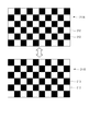
- FIG. 2 is a diagram showing a first example of the calibration pattern in this embodiment.
- the display unit 210 switches and displays the calibration pattern 211A and the calibration pattern 211B. That is, the display unit 210 first changes the brightness of the plane area corresponding to the display surface of the display or the projection surface of the projector according to the calibration pattern 211A, and then changes it according to the calibration pattern 211B. As a result, in the plane area, first, the spatial distribution of the luminance according to the calibration pattern 211A appears, and it instantaneously changes to the spatial distribution of the luminance according to the calibration pattern 211B.
- the calibration patterns 211A and 211B include high-luminance regions 212 and low-luminance regions 213 arranged according to a grid pattern, and the high-luminance regions 212 and low-luminance regions 213 in the calibration pattern 211B are inverted with respect to the calibration pattern 211A.
- the high-luminance regions 212 and the low-luminance regions 213 may be arranged according to an arbitrary spatial pattern without being limited to the grid pattern.
- the event signal indicating the brightness is generated, and similarly, the sensor corresponding to the low brightness region 213 generates the event signal indicating the brightness decrease.
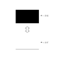
- FIG. 3 is a diagram showing a second example of the calibration pattern in this embodiment.
- the display unit 210 sequentially switches and displays the calibration pattern 211C, the calibration pattern 211D, the calibration pattern 211E, and the calibration pattern 211F. That is, the display unit 210 sequentially changes the brightness of the plane area corresponding to the display surface of the display or the projection surface of the projector according to the calibration patterns 211C to 211F. As a result, in the plane area, the spatial distribution of the brightness according to each of the calibration patterns 211C to 211F appears sequentially while being instantaneously switched.
- the calibration pattern 211C, the calibration pattern 211D, the calibration pattern 211E, and the calibration pattern 211F have uniform brightness in the entire area of the display unit 210 and different brightness values.
- the luminance value is lowest in the calibration pattern 211C, higher in the calibration pattern 211D, higher in the calibration pattern 211E, and highest in the calibration pattern 211F.
- the brightness value is switched in four steps in the illustrated example, the brightness value may be switched in more steps.
- the display of the calibration pattern is sequentially switched so that the luminance value monotonously increases, but conversely, the display of the calibration pattern may be sequentially switched so that the luminance value monotonously decreases.
- the display unit 210 of the sensors 111A, 111B, ... Things When the image displayed on the display unit 210 is sequentially switched from the calibration pattern C to the calibration pattern F in the calibration system 10 described above, the display unit 210 of the sensors 111A, 111B, ... Things generate event signals. For example, when an event signal is generated when the calibration pattern 211D is switched to the calibration pattern 211E, the threshold th at which the sensor detects the brightness change is between the brightness value of the calibration pattern 211D and the brightness value of the calibration pattern 211E. is there. For example, when the vision sensor 110 is manufactured, the sensors 111A, 111B, ... May be adjusted or replaced if the threshold value specified as described above is not within the designed range.
- FIG. 4 is a diagram showing a third example of the calibration pattern in this embodiment.
- the display unit 210 switches between and displays the calibration pattern 211C and the calibration pattern 211F, as in the example described with reference to FIG. 2 above.
- the calibration pattern 211C is a calibration pattern including a uniform low luminance area
- the calibration pattern 211F is a calibration pattern including a uniform high luminance area.
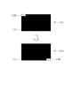
- FIG. 5 is a diagram showing a fourth example of the calibration pattern in this embodiment.
- the display unit 210 switches between the calibration pattern 211G and the calibration pattern 211H and displays the same as in the example described with reference to FIG. 2 above.
- Most of the calibration pattern 211G is the low-brightness area 213, but the high-brightness area 212A, which is the brightness reversal area, is arranged in the first part of the plane area, specifically, the upper left part.
- the low-brightness area 213 is the low-brightness area 213.
- a brightness area 212B is arranged.
- the brightness inversion region may be arranged at an arbitrary position without being limited to the upper left and lower right.
- most of the calibration pattern may be the high-brightness area 212, and a low-brightness area 213 may be arranged in a part of the high-brightness area 212.
- the sensor that detects the luminance change of the first portion of the planar area of the sensor array 111 has a high luminance area.
- An event signal indicating a decrease in brightness is generated due to the change of 212A to the low brightness area 213.
- an event signal indicating the brightness increase is generated due to the change of the low brightness area 213 to the high brightness area 212B.
- the sensor that detects the brightness change other than the first portion and the second portion does not generate an event signal.
- 10 ... Calibration system, 100 ... Sensor device, 110 ... Vision sensor, 111 ... Sensor array, 111A, 111B ... Sensor, 112 ... Processing circuit, 120 ... Control part, 121 ... Communication interface, 122 ... Processing circuit, 123 ... Memory, Reference numeral 200 ... Display device, 210 ... Display unit, 220 ... Display control unit, 221 ... Communication interface, 222 ... Processing circuit, 223 ... Memory, 211A to 211H ... Calibration pattern, 212 ... High brightness area, 213 ... Low brightness area.
Landscapes
- Engineering & Computer Science (AREA)
- Multimedia (AREA)
- Signal Processing (AREA)
- Physics & Mathematics (AREA)
- General Physics & Mathematics (AREA)
- Biomedical Technology (AREA)
- Theoretical Computer Science (AREA)
- Health & Medical Sciences (AREA)
- Computer Vision & Pattern Recognition (AREA)
- General Health & Medical Sciences (AREA)
- Geometry (AREA)
- Chemical & Material Sciences (AREA)
- Analytical Chemistry (AREA)
- Controls And Circuits For Display Device (AREA)
- Transforming Light Signals Into Electric Signals (AREA)
- Testing, Inspecting, Measuring Of Stereoscopic Televisions And Televisions (AREA)
- Control Of Indicators Other Than Cathode Ray Tubes (AREA)
Priority Applications (2)
| Application Number | Priority Date | Filing Date | Title |
|---|---|---|---|
| US17/283,718 US12033354B2 (en) | 2018-10-17 | 2019-10-10 | Sensor calibration system, display control apparatus, program, and sensor calibration method |
| KR1020217011477A KR102513670B1 (ko) | 2018-10-17 | 2019-10-10 | 센서 보정 시스템, 디스플레이 제어 장치, 프로그램, 및 센서 보정 방법 |
Applications Claiming Priority (2)
| Application Number | Priority Date | Filing Date | Title |
|---|---|---|---|
| JP2018-195505 | 2018-10-17 | ||
| JP2018195505A JP7251942B2 (ja) | 2018-10-17 | 2018-10-17 | センサの校正システム、表示制御装置、プログラム、およびセンサの校正方法 |
Publications (1)
| Publication Number | Publication Date |
|---|---|
| WO2020080237A1 true WO2020080237A1 (ja) | 2020-04-23 |
Family
ID=70283469
Family Applications (1)
| Application Number | Title | Priority Date | Filing Date |
|---|---|---|---|
| PCT/JP2019/039932 Ceased WO2020080237A1 (ja) | 2018-10-17 | 2019-10-10 | センサの校正システム、表示制御装置、プログラム、およびセンサの校正方法 |
Country Status (4)
| Country | Link |
|---|---|
| US (1) | US12033354B2 (enExample) |
| JP (1) | JP7251942B2 (enExample) |
| KR (1) | KR102513670B1 (enExample) |
| WO (1) | WO2020080237A1 (enExample) |
Cited By (10)
| Publication number | Priority date | Publication date | Assignee | Title |
|---|---|---|---|---|
| WO2023288067A1 (en) * | 2021-07-15 | 2023-01-19 | Summer Robotics, Inc. | Automatic parameter adjustment for scanning event cameras |
| US11704835B2 (en) | 2021-07-29 | 2023-07-18 | Summer Robotics, Inc. | Dynamic calibration of 3D acquisition systems |
| US11785200B1 (en) | 2022-03-14 | 2023-10-10 | Summer Robotics, Inc. | Stage studio for immersive 3-D video capture |
| US11808857B2 (en) | 2021-08-27 | 2023-11-07 | Summer Robotics, Inc. | Multi-sensor superresolution scanning and capture system |
| US11974055B1 (en) | 2022-10-17 | 2024-04-30 | Summer Robotics, Inc. | Perceiving scene features using event sensors and image sensors |
| US12111180B2 (en) | 2021-07-01 | 2024-10-08 | Summer Robotics, Inc. | Calibration of sensor position offsets based on rotation and translation vectors for matched trajectories |
| US12276730B2 (en) | 2022-11-08 | 2025-04-15 | Summer Robotics, Inc. | Virtual fences in air, water, and space |
| US12401905B2 (en) | 2022-07-14 | 2025-08-26 | Summer Robotics, Inc. | Foveated robotic vision system |
| US12416804B1 (en) | 2024-05-08 | 2025-09-16 | Summer Robotics, Inc. | Kaleidoscopic laser beam projection system |
| US12487359B2 (en) | 2020-12-14 | 2025-12-02 | Summer Robotics, Inc. | Perceiving objects based on sensing surfaces and sensing surface motion |
Families Citing this family (5)
| Publication number | Priority date | Publication date | Assignee | Title |
|---|---|---|---|---|
| JP2020161987A (ja) * | 2019-03-27 | 2020-10-01 | ソニー株式会社 | 車両用撮影システム |
| CN112532870B (zh) * | 2020-11-09 | 2021-11-30 | 福建福瑞康信息技术有限公司 | 多终端自适应数据处理系统、方法及计算机可读存储介质 |
| JP2022188987A (ja) * | 2021-06-10 | 2022-12-22 | キヤノン株式会社 | 情報処理装置、情報処理方法およびプログラム |
| CN115250349B (zh) * | 2022-07-26 | 2024-12-13 | 深圳锐视智芯科技有限公司 | 一种传感器测试方法及相关装置 |
| KR20240113050A (ko) * | 2023-01-13 | 2024-07-22 | 엘지디스플레이 주식회사 | 표시 패널의 휘도 보정 방법 |
Citations (4)
| Publication number | Priority date | Publication date | Assignee | Title |
|---|---|---|---|---|
| JP2007071618A (ja) * | 2005-09-06 | 2007-03-22 | Mitsubishi Electric Corp | 画質検査装置 |
| JP2015115962A (ja) * | 2013-12-11 | 2015-06-22 | アンリツ カンパニー | 自動露出モードで作動するカメラの輝度応答を測定するためのシステム及び方法 |
| US20170155805A1 (en) * | 2015-11-26 | 2017-06-01 | Samsung Electronics Co., Ltd. | Method and apparatus for capturing an image of an object by tracking the object |
| JP2018501675A (ja) * | 2014-09-30 | 2018-01-18 | クアルコム,インコーポレイテッド | センサ素子アレイにおける特徴計算 |
Family Cites Families (6)
| Publication number | Priority date | Publication date | Assignee | Title |
|---|---|---|---|---|
| JP3705180B2 (ja) * | 2001-09-27 | 2005-10-12 | セイコーエプソン株式会社 | 画像表示システム、プログラム、情報記憶媒体および画像処理方法 |
| US20100201275A1 (en) * | 2009-02-06 | 2010-08-12 | Cok Ronald S | Light sensing in display device |
| KR101880998B1 (ko) | 2011-10-14 | 2018-07-24 | 삼성전자주식회사 | 이벤트 기반 비전 센서를 이용한 동작 인식 장치 및 방법 |
| US20160111062A1 (en) * | 2014-10-15 | 2016-04-21 | Intel Corporation | Ambient light-based image adjustment |
| US9489735B1 (en) * | 2015-09-17 | 2016-11-08 | Qualcomm Incorporated | Multiplexed temporal calibration for event-based cameras |
| US20180146149A1 (en) | 2016-11-21 | 2018-05-24 | Samsung Electronics Co., Ltd. | Event-based sensor, user device including the same, and operation method of the same |
-
2018
- 2018-10-17 JP JP2018195505A patent/JP7251942B2/ja active Active
-
2019
- 2019-10-10 WO PCT/JP2019/039932 patent/WO2020080237A1/ja not_active Ceased
- 2019-10-10 KR KR1020217011477A patent/KR102513670B1/ko active Active
- 2019-10-10 US US17/283,718 patent/US12033354B2/en active Active
Patent Citations (4)
| Publication number | Priority date | Publication date | Assignee | Title |
|---|---|---|---|---|
| JP2007071618A (ja) * | 2005-09-06 | 2007-03-22 | Mitsubishi Electric Corp | 画質検査装置 |
| JP2015115962A (ja) * | 2013-12-11 | 2015-06-22 | アンリツ カンパニー | 自動露出モードで作動するカメラの輝度応答を測定するためのシステム及び方法 |
| JP2018501675A (ja) * | 2014-09-30 | 2018-01-18 | クアルコム,インコーポレイテッド | センサ素子アレイにおける特徴計算 |
| US20170155805A1 (en) * | 2015-11-26 | 2017-06-01 | Samsung Electronics Co., Ltd. | Method and apparatus for capturing an image of an object by tracking the object |
Cited By (13)
| Publication number | Priority date | Publication date | Assignee | Title |
|---|---|---|---|---|
| US12487359B2 (en) | 2020-12-14 | 2025-12-02 | Summer Robotics, Inc. | Perceiving objects based on sensing surfaces and sensing surface motion |
| US12111180B2 (en) | 2021-07-01 | 2024-10-08 | Summer Robotics, Inc. | Calibration of sensor position offsets based on rotation and translation vectors for matched trajectories |
| WO2023288067A1 (en) * | 2021-07-15 | 2023-01-19 | Summer Robotics, Inc. | Automatic parameter adjustment for scanning event cameras |
| US12148185B2 (en) | 2021-07-15 | 2024-11-19 | Summer Robotics, Inc. | Automatic parameter adjustment for scanning event cameras |
| US11704835B2 (en) | 2021-07-29 | 2023-07-18 | Summer Robotics, Inc. | Dynamic calibration of 3D acquisition systems |
| US11887340B2 (en) | 2021-07-29 | 2024-01-30 | Summer Robotics, Inc. | Dynamic calibration of 3D acquisition systems |
| US11808857B2 (en) | 2021-08-27 | 2023-11-07 | Summer Robotics, Inc. | Multi-sensor superresolution scanning and capture system |
| US11785200B1 (en) | 2022-03-14 | 2023-10-10 | Summer Robotics, Inc. | Stage studio for immersive 3-D video capture |
| US12401905B2 (en) | 2022-07-14 | 2025-08-26 | Summer Robotics, Inc. | Foveated robotic vision system |
| US11974055B1 (en) | 2022-10-17 | 2024-04-30 | Summer Robotics, Inc. | Perceiving scene features using event sensors and image sensors |
| US12262127B2 (en) | 2022-10-17 | 2025-03-25 | Summer Robotics, Inc. | Perceiving scene features using event sensors and image sensors |
| US12276730B2 (en) | 2022-11-08 | 2025-04-15 | Summer Robotics, Inc. | Virtual fences in air, water, and space |
| US12416804B1 (en) | 2024-05-08 | 2025-09-16 | Summer Robotics, Inc. | Kaleidoscopic laser beam projection system |
Also Published As
| Publication number | Publication date |
|---|---|
| JP2020065149A (ja) | 2020-04-23 |
| JP7251942B2 (ja) | 2023-04-04 |
| US12033354B2 (en) | 2024-07-09 |
| US20210327090A1 (en) | 2021-10-21 |
| KR20210093233A (ko) | 2021-07-27 |
| KR102513670B1 (ko) | 2023-03-24 |
Similar Documents
| Publication | Publication Date | Title |
|---|---|---|
| WO2020080237A1 (ja) | センサの校正システム、表示制御装置、プログラム、およびセンサの校正方法 | |
| JP2020065149A5 (enExample) | ||
| US20230120133A1 (en) | Optical distance measurement system with dynamic exposure time | |
| JP5257375B2 (ja) | 画像処理装置および画像処理方法 | |
| CN102445688A (zh) | 组合的飞行时间和图像传感器系统 | |
| JP7162124B2 (ja) | 画像処理装置、投影システム、画像処理方法、及び画像処理プログラム | |
| JP7341145B2 (ja) | 皮膚を画像化する装置 | |
| US20120120007A1 (en) | Transparent display apparatus and method of controlling the same | |
| US11536667B2 (en) | Image inspection apparatus and image inspection method | |
| CN110858296B (zh) | 指纹感测装置以及指纹感测方法 | |
| US20190156500A1 (en) | Distance measurement system applicable to different reflecting surfaces and computer system | |
| KR102772019B1 (ko) | 디스플레이 장치 및 그 제어 방법 | |
| JP6368593B2 (ja) | 画像処理プログラム、情報処理システム、画像処理方法 | |
| US10552111B2 (en) | Control device | |
| US20180220053A1 (en) | Processing device, processing method, system, and article manufacturing method | |
| US9389731B2 (en) | Optical touch system having an image sensing module for generating a two-dimensional image and converting to a one-dimensional feature | |
| CN102163103A (zh) | 触控式输入方法及其装置 | |
| JP5838081B2 (ja) | 光特性ムラ測定装置及び光特性ムラ測定方法 | |
| CN110047426A (zh) | Led像素、像素模块、显示模组及小间距led屏 | |
| CN111982477B (zh) | 显示面板的测试方法、测试装置 | |
| WO2020021868A1 (ja) | 投影装置とその制御方法及び制御プログラム | |
| JP6386837B2 (ja) | 画像処理プログラム、情報処理システム、情報処理装置、画像処理方法 | |
| JP2009222399A (ja) | 画像ゲイン調整装置およびその方法、並びに三次元形状測定装置 | |
| JP2020112419A (ja) | 空間光変調素子の検査装置及び検査方法 | |
| KR100189939B1 (ko) | 음극선관의 초점 조정 방법 |
Legal Events
| Date | Code | Title | Description |
|---|---|---|---|
| 121 | Ep: the epo has been informed by wipo that ep was designated in this application |
Ref document number: 19872908 Country of ref document: EP Kind code of ref document: A1 |
|
| NENP | Non-entry into the national phase |
Ref country code: DE |
|
| 122 | Ep: pct application non-entry in european phase |
Ref document number: 19872908 Country of ref document: EP Kind code of ref document: A1 |