WO2020080077A1 - 複数の電線の接続構造 - Google Patents
複数の電線の接続構造 Download PDFInfo
- Publication number
- WO2020080077A1 WO2020080077A1 PCT/JP2019/038494 JP2019038494W WO2020080077A1 WO 2020080077 A1 WO2020080077 A1 WO 2020080077A1 JP 2019038494 W JP2019038494 W JP 2019038494W WO 2020080077 A1 WO2020080077 A1 WO 2020080077A1
- Authority
- WO
- WIPO (PCT)
- Prior art keywords
- electric wires
- wires
- core
- tubular member
- core wire
- Prior art date
- Legal status (The legal status is an assumption and is not a legal conclusion. Google has not performed a legal analysis and makes no representation as to the accuracy of the status listed.)
- Ceased
Links
Images



Classifications
-
- H—ELECTRICITY
- H01—ELECTRIC ELEMENTS
- H01R—ELECTRICALLY-CONDUCTIVE CONNECTIONS; STRUCTURAL ASSOCIATIONS OF A PLURALITY OF MUTUALLY-INSULATED ELECTRICAL CONNECTING ELEMENTS; COUPLING DEVICES; CURRENT COLLECTORS
- H01R4/00—Electrically-conductive connections between two or more conductive members in direct contact, i.e. touching one another; Means for effecting or maintaining such contact; Electrically-conductive connections having two or more spaced connecting locations for conductors and using contact members penetrating insulation
- H01R4/02—Soldered or welded connections
-
- H—ELECTRICITY
- H01—ELECTRIC ELEMENTS
- H01R—ELECTRICALLY-CONDUCTIVE CONNECTIONS; STRUCTURAL ASSOCIATIONS OF A PLURALITY OF MUTUALLY-INSULATED ELECTRICAL CONNECTING ELEMENTS; COUPLING DEVICES; CURRENT COLLECTORS
- H01R43/00—Apparatus or processes specially adapted for manufacturing, assembling, maintaining, or repairing of line connectors or current collectors or for joining electric conductors
- H01R43/02—Apparatus or processes specially adapted for manufacturing, assembling, maintaining, or repairing of line connectors or current collectors or for joining electric conductors for soldered or welded connections
-
- H—ELECTRICITY
- H02—GENERATION; CONVERSION OR DISTRIBUTION OF ELECTRIC POWER
- H02G—INSTALLATION OF ELECTRIC CABLES OR LINES, OR OF COMBINED OPTICAL AND ELECTRIC CABLES OR LINES
- H02G15/00—Cable fittings
- H02G15/08—Cable junctions
- H02G15/18—Cable junctions protected by sleeves, e.g. for communication cable
Definitions
- the technology disclosed in this specification relates to a connection structure of a plurality of electric wires.
- Patent Document 1 Japanese Patent Laid-Open No. 2005-322544
- the joint part where the conductors of a plurality of insulated wires are twisted together and ultrasonically welded as described above is not torn when some insulated wires are separated from other insulated wires by a tear strength test or the like. Therefore, there is concern that the connection reliability at the joint may be reduced.
- the technique disclosed in the present specification includes a plurality of electric wires having a conductive core wire, and a cylindrical tubular member that is collectively inserted into the core wires of the plurality of electric wires in a bundled state.
- a connecting structure of a plurality of electric wires wherein a part of the tubular member through which the core wires of the plurality of electric wires are inserted and the plurality of core wires are integrally joined by welding, and the tubular shape
- a core wire joining portion is formed in which the core wires of the plurality of electric wires protruding from the member are joined to each other.
- connection structure of a plurality of electric wires having such a configuration, the core wires of the plurality of electric wires in a bundled state and the tubular member are integrally joined at the integrally joined portion, and the plurality of core wires are joined to the tubular member at the integrally joined portion. It has been restrained by. Therefore, as compared with the conventional method in which the core wires of a plurality of electric wires are twisted together and joined by welding, even when some electric wires are separated from other electric wires in a tear strength test, etc. It is possible to relieve the application of stress and improve the joint strength of the portion where the core wires of the plurality of electric wires are joined. Further, since the core wire and the tubular member are integrated at the integrally joined portion, it is possible to prevent the tubular member from falling off from the plurality of electric wires.
- the core wires of the plurality of electric wires protruding from the tubular member are securely joined by the core wire joining portion, the connection reliability between the plurality of electric wires can be reliably ensured.
- connection structure for a plurality of electric wires disclosed in this specification may have the following configuration.
- the integral joint portion and the core wire joint portion may be arranged adjacent to each other.
- the integral joint portion and the core wire joint portion can be formed by welding at once between the anvil and the welding horn of the ultrasonic welding device. Therefore, for example, the connecting work can be simplified as compared with the case where the integral joining portion and the core wire joining portion are separated and joined separately.
- the core wire of the plurality of electric wires is pulled out from the tubular member to the side opposite to the core wire joining portion, and the end portions of the tubular member on the side where the plurality of electric wires are pulled out have the plurality of It is also possible to adopt a configuration in which a diameter-increased portion that increases in diameter in the direction in which the electric wire is pulled out is provided.
- the electric wires are arranged along the expanded diameter portion and the electric wires drawn out from the tubular member are sharply bent. Can be suppressed. Accordingly, for example, compared with the case where the expanded portion is not provided at the end of the tubular member on which the electric wire is pulled out, the stress applied to the integral joint portion and the core wire joint portion can be relaxed and It is possible to prevent the electric wire from being damaged by the edge at the end of the strip-shaped member.
- the part of the plurality of electric wires that is pulled out from the expanded diameter portion may be the core wire.
- the core wire When the portion drawn out from the tubular member is the core wire, and when the core wire is sharply bent, there is a concern that the core wire may be damaged by the edge at the end of the tubular member.
- the portion of the electric wire that is pulled out from the tubular member is the core wire, but since the end portion of the tubular member on the side where the electric wire is pulled out is provided with the expanded diameter portion, Even when bent, the core wire is arranged along the inner surface of the expanded diameter portion, and the core wire is prevented from coming into contact with the edge of the end portion of the tubular member. That is, this structure is very effective when the portion pulled out from the tubular member is the core wire.
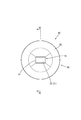
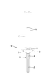
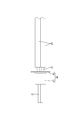
- FIG. 1 Perspective view of the harness according to the embodiment Front view of harness Side view of harness VI-VI line sectional view of FIG.
- a side view showing a state before inserting a plurality of electric wires into a tubular member A perspective view showing a state in which a plurality of electric wires are inserted into a tubular member.
- the present embodiment exemplifies a harness 10 in which a plurality of covered electric wires (an example of “electric wires”) 20 are bundled and connected.
- the harness 10 of the present embodiment includes four covered electric wires 20 and a tubular member 40 that is inserted all together in a bundled state of the four covered electric wires 20.
- the harness 10 of the present embodiment is an example of a connection structure of a plurality of electric wires.
- each covered electric wire 20 is formed by covering a conductive core wire 21 with an insulating covering 23.
- the core wire 21 is formed by twisting a plurality of strands, and for example, any metal such as copper, copper alloy, aluminum, and aluminum alloy can be appropriately selected as necessary.
- the core wire 21 is exposed by peeling off the covering 23, and the four exposed core wires 21 are inserted into the tubular member 40. Further, in the core wire 21 inserted into the tubular member 40, four core wires 21 projecting forward from a tubular body 41 of the tubular member 40, which will be described later, are joined to each other as shown in FIGS. 1 to 4. It is the core wire joining portion 25.
- the tubular member 40 has a substantially tubular shape in which the rear end, which is one end, is expanded, and is a so-called metal eyelet.
- the metal forming the tubular member 40 is a metal that can be ultrasonically welded, and for example, brass, stainless steel, aluminum, aluminum alloy, copper, copper alloy, or any other metal can be appropriately selected as necessary.
- a preferable metal for the tubular member is a metal having a higher strength than the conductor strength of the core wire 21 of the covered electric wire 20, and the tubular member 40 of the present embodiment is made of brass.
- the tubular member 40 is configured to include a tubular main body 41 having a rectangular tubular shape joined to the core wires 21 of the plurality of covered electric wires 20, and an enlarged diameter portion 43 connected to the tubular main body 41.
- the tubular body 41 has a substantially cylindrical shape before being joined to the core wires 21 of the plurality of covered electric wires 20, as shown in FIGS. 5 to 8. As shown in FIGS. 1 to 4, the tubular portion main body 41 is inserted in a bundle with the core wires 21 of the four covered electric wires 20 and joined to the four core wires 21 to form a rectangular tubular shape. And the core wire 21 and the cylinder body 41 are bonded to each other so that the four core wires 21 and the cylinder body 41 are integrated to form a prismatic integral bonding portion 45.
- the integral joint portion 45 is formed so as to be continuous with the core wire joint portion 25 so as to be adjacent to the front and rear, and the plate thickness dimension of the tubular portion main body 41 is as shown in FIG. 4 by being joined to the four core wires 21. Moreover, it is thinner than the plate thickness dimension of the expanded diameter portion 43.
- the length dimension in the front-rear direction which is the axial direction of the tube body 41, is the front-rear direction (extending direction of the core wire 21) of the core wire 21 exposed at the end of the covered electric wire 20.
- the length is set shorter than the length dimension, and accordingly, the integral joint portion 45 is also configured to be shorter than the length dimension in the front-rear direction of the core wire 21 exposed from the coating 23.
- the enlarged diameter portion 43 is formed continuously with the rear end of the tubular body 41.
- the diameter-expanded portion 43 is increased in diameter in a direction away from the axis of the tubular member 40 toward the rear, and the rear end of the diameter-enlarged portion 43 extends in a direction orthogonal to the axis of the tubular member 40. It is said that
- the plurality of covered electric wires 20 are pulled out from the tubular member 40 toward the rear, which is the opposite side to the core wire joining portion 25, and the rear side of the tubular member 40 on which the plurality of covered electric wires 20 is pulled out.
- the end portion is provided with a diameter-expanded portion 43 whose diameter increases toward the direction (backward direction) in which the plurality of covered electric wires 20 are pulled out.
- the core wire 21 of each covered electric wire 20 follows the inner surface 43 A of the expanded diameter portion 43.
- the present embodiment is configured as described above, and subsequently, an example of a method of manufacturing the harness 10 will be described below.
- the sheath 23 is peeled off to expose the core wire 21 at each end of each of the covered electric wires 20.
- each core wire 21 of the covered electric wire 20 is formed by twisting a plurality of element wires. Therefore, if the strands of the respective core wires 21 are unraveled, there is a concern that the inserting work for inserting the plurality of core wires 21 into the tubular member 40 at once becomes complicated.
- the rear end portion of the tubular member 40 on the side where the core wire 21 of the covered electric wire 20 is introduced is provided with the enlarged diameter portion 43 that is enlarged toward the rear, as shown in FIG. Has been. That is, even when the core wires 21 of the plurality of covered electric wires 20 are frayed, the plurality of core wires 21 are guided by the inner surface 43A of the expanded diameter portion 43 together with the fray, and the plurality of core wires 21 can be easily attached to the tubular body 41. You can enter. That is, it is possible to prevent the inserting work of inserting the plurality of core wires 21 into the tubular member 40 all at once from being complicated.
- the plurality of core wires 21 projecting forward from the cylinder body 41 of the tubular member 40 are joined together by using an ultrasonic welding device (not shown), and the plurality of core wires 41 and the cylinder body 41 having the plurality of core wires 21 inserted thereinto are joined together.
- the core wire 21 is joined by using an ultrasonic welding device.
- the ultrasonic welding device is a device having a well-known structure that includes an anvil that is disposed below and a welding horn that is disposed so as to be capable of advancing and retracting from the upper side of the anvil and that is opposed to above the anvil.
- a cylinder main body 41 having a plurality of core wires 21 inserted therein is arranged.
- the welding horn is lowered to press the core wires 21 and the cylinder body 41 from above and below by the anvil and the welding horn, and the core wires 21 and the cylinder body 41 are axially aligned. Apply ultrasonic vibration. Then, the plurality of core wires 21 are welded to each other to form the core wire joint portion 25. In addition, the plurality of core wires 21 and the tubular body 41 are joined by welding to form an integral joint 45. As a result, the harness 10 to which the plurality of covered electric wires 20 are connected is completed.
- the integral joint portion 45 and the core wire joint portion 25 are arranged in adjacent positions.
- the plurality of core wires 21 and the tubular body 41 can be collectively sandwiched by the anvil and the welding horn, and the integral joint portion 45 and the core joint portion 25 can be welded at one time to be formed. That is, for example, the connecting work can be simplified as compared with the case where the integral joining portion and the core wire joining portion are separated and joined separately.
- a plurality of covered electric wires 20 having conductive core wires 21 and the core wires 21 of the plurality of covered electric wires 20 are collectively inserted.
- the core wire joining portion 25 is formed by joining the core wires 21 of the plurality of covered electric wires 20 protruding from the tubular member 40 to each other.
- the core wires 21 of the plurality of covered electric wires 20 in a bundled state and a part of the tubular member 40 are integrally joined at the integrally joined portion 45, and the plurality of core wires 21 at the integrally joined portion 45. Is constrained by the tubular member 40.
- the present embodiment as compared with the conventional one in which core wires of a plurality of covered electric wires are twisted together and joined by welding, some of the covered electric wires 20 are separated from other covered electric wires 20 in a tear strength test or the like. Even when the core wires 21 are separated from each other, it is possible to relieve the stress applied to the interface between the core wires 21 and improve the bonding strength of the integrally bonded portion 45. Further, since the core wire 21 and the tubular member 40 are integrally joined at the integrally joined portion 45, it is possible to prevent the tubular member 40 from falling off the covered electric wire 20.
- the core wires 21 of the plurality of covered electric wires 20 protruding from the tubular member 40 are reliably joined by the core wire joining portion 25, so that the connection reliability between the plurality of covered electric wires 20 is ensured. Can be secured.
- the integrated joint portion 45 and the core wire joint portion 25 are arranged at positions adjacent to each other. That is, since the integrated joint portion 45 and the core wire joint portion 25 can be formed by welding at a time between the anvil and the welding horn of the ultrasonic welding apparatus, for example, the integral joint portion and the core wire joint portion are respectively formed.
- the connecting work can be simplified as compared with the case of separately joining them separately.
- the core wires 21 of the plurality of covered electric wires 20 of the present embodiment are pulled out from the tubular member 40 to the rear side, which is the side opposite to the core wire joint portion 25, and the side on which the plurality of covered electric wires 20 are pulled out in the tubular member 40.
- the rear end portion is provided with an enlarged diameter portion 43 that increases in diameter toward the rear (the direction in which the plurality of covered electric wires 20 are pulled out).
- the covered electric wires 20 are arranged along the expanded diameter portion 43 and pulled out from the tubular member 40. Can be suppressed from being sharply bent. As a result, for example, the stress applied to the integrated joint portion 45 and the core wire joint portion 25 can be relaxed as compared with the case where the expanded portion is not provided at the end portion of the tubular member on the side where the electric wire is pulled out. It is possible to prevent the covered electric wire 20 from being damaged by the edge at the end of the tubular member 40.
- the portion of the plurality of covered electric wires 20 that is pulled out from the tubular member 40 is the core wire 21, and when the core wire 21 is sharply bent, the end of the tubular member 40 There is a concern that the core wire 21 may be damaged by the edge of the portion.
- the portion of the covered electric wire 20 that is pulled out from the tubular member 40 is the core wire 21, it extends to the rear end portion of the tubular member 40 where the covered electric wire 20 is pulled out. Since the diameter portion 43 is provided, even when the core wire 21 is sharply bent, the core wire 21 is arranged along the inner surface 43A of the expanded diameter portion 43, and the core wire 21 is at the end portion of the tubular member 40. The contact with the edge of is suppressed. That is, the configuration of the present embodiment is very effective when the portion pulled out from the tubular member 40 is the core wire 21.
- the core wire joint portion 25 and the integral joint portion 45 are adjacent to each other in the front-rear direction.
- the present invention is not limited to this, and the core wire joint portion and the integral joint portion may be separately joined such that the core wire joint portion and the integral joint portion are separated from each other in the front-rear direction.
- the portion of the covered electric wire 20 that is pulled out from the expanded diameter portion 43 is the core wire 21.
- the configuration is not limited to this, and the portion drawn out from the expanded diameter portion 43 may be covered with a coating.
- the core wire 21 is connected to the covered electric wire 20 covered with the cover 23.
- the technique disclosed in the present specification may be applied to a so-called bare wire in which the core wire is not covered with the coating.
- Harness an example of "connection structure of a plurality of electric wires"
- Coated electric wire an example of "electric wire”
- core wire 25 core wire joint portion 40: tubular member 43: expanded diameter portion 45: integral joint portion
Landscapes
- Engineering & Computer Science (AREA)
- Manufacturing & Machinery (AREA)
- Connections Effected By Soldering, Adhesion, Or Permanent Deformation (AREA)
- Manufacturing Of Electrical Connectors (AREA)
- Cable Accessories (AREA)
Abstract
本明細書によって開示されるハーネス10は、導電性の芯線21を有する複数の被覆電線20と、複数の被覆電線20の芯線21が束ねられた状態で一括して挿通される筒状の筒状部材40とを備え、複数の被覆電線20の芯線21が挿通された筒状部材40の一部と複数の芯線21とが溶接によって一体に接合された一体接合部45と、筒状部材40から突出した複数の被覆電線20の芯線21が互いに接合された芯線接合部25とを備えている構成とした。
Description
本明細書によって開示される技術は、複数の電線の接続構造に関する。
複数本の絶縁電線の導体同士が接合された電線の接続構造として、特開2005-322544号公報(下記特許文献1)に記載のものが知られている。この電線の接続構造は、複数本の絶縁電線の導体を束ねて捻った後、超音波溶接によって接合することにより複数本の絶縁電線同士を接続している。
ところで、上記のように複数本の絶縁電線の導体を捻り合わせて超音波溶接した接合部は、引き裂き強度試験などによって、一部の絶縁電線が他の絶縁電線から引き離されると、接合部が引き裂かれて接合部における接続信頼性が低下してしまうことが懸念される。
本明細書では、複数本の電線が接合された部分の接合強度を向上させると共に、電線が接合された部分の接続信頼性を確保する技術を開示する。
本明細書によって開示される技術は、導電性の芯線を有する複数の電線と、前記複数の電線の前記芯線が束ねられた状態で一括して挿通される筒状の筒状部材とを備えた複数の電線の接続構造であって、前記複数の電線の前記芯線が挿通された前記筒状部材の一部と前記複数の芯線とが溶接によって一体に接合された一体接合部と、前記筒状部材から突出した前記複数の電線の前記芯線が互いに接合された芯線接合部とを備えている構成とした。
このような構成の複数の電線の接続構造によると、束ねられた状態の複数の電線の芯線と筒状部材とが一体接合部において一体に接合され、一体接合部において複数の芯線が筒状部材に拘束された状態となっている。したがって、従来のように、複数の電線の芯線を捻り合わせて溶接によって接合したものに比べて、引き裂き強度試験などにおいて一部の電線が他の電線から引き離された場合でも、芯線同士の界面に応力が加わることを緩和し、複数の電線の芯線が接合された部分の接合強度を向上させることができる。また、芯線と筒状部材とが一体接合部において一体となっているから、筒状部材が複数の電線から脱落することを防ぐことができる。
また、筒状部材から突出した複数の電線の芯線同士が芯線接合部によって確実に接合されているから、複数の電線間の接続信頼性を確実に確保することができる。
本明細書によって開示される複数の電線の接続構造は、以下の構成としてもよい。
前記一体接合部と前記芯線接合部とは隣り合った位置に配置されている構成としてもよい。このような構成によると、一体接合部と芯線接合部とを超音波溶接装置のアンビルと溶接ホーンとの間において一度に溶接して形成することができる。したがって、例えば、一体接合部と芯線接合部とをそれぞれ離して個別に接合する場合に比べて、接続作業を簡素化することができる。
前記一体接合部と前記芯線接合部とは隣り合った位置に配置されている構成としてもよい。このような構成によると、一体接合部と芯線接合部とを超音波溶接装置のアンビルと溶接ホーンとの間において一度に溶接して形成することができる。したがって、例えば、一体接合部と芯線接合部とをそれぞれ離して個別に接合する場合に比べて、接続作業を簡素化することができる。
前記複数の電線の前記芯線は、前記筒状部材から前記芯線接合部とは反対側に引き出されており、前記筒状部材の前記複数の電線が引き出される側の端部には、前記複数の電線が引き出される方向に向かうほど拡径する拡径部が設けられている構成としてもよい。
このような構成によると、引き裂き試験などによって、一部の電線が他の電線から引き離される場合でも、電線が拡径部に沿って配され、筒状部材から引き出された電線が急激に屈曲されることを抑制することができる。これにより、例えば、筒状部材において電線が引き出される側の端部に拡径部が設けられていない場合に比べて、一体接合部や芯線接合部に加わる応力を緩和することができると共に、筒状部材の端部におけるエッジによって電線が損傷することを抑制することができる。
前記複数の電線において前記拡径部から引き出される部分は、前記芯線とされている構成としてもよい。筒状部材から引き出される部分が芯線とされている場合、芯線が急激に屈曲された場合には、筒状部材の端部にけるエッジによって芯線が損傷することが懸念される。
ところが、当該構成は、電線において筒状部材から引き出される部分は芯線とされているものの、筒状部材において電線が引き出される側の端部には拡径部が設けられているから、芯線が急激に屈曲された場合であっても、芯線は拡径部の内面に沿って配され、芯線が筒状部材の端部のエッジに接触することが抑制される。すなわち、当該構成は、筒状部材から引き出される部分が芯線の場合に、非常に有効である。
本明細書によって開示される技術によれば、複数本の電線が接合された部分の接合強度を向上させる共に、電線が接合された部分の接続信頼性を確保することができる。
<実施形態>
本明細書に開示された技術における一実施形態について図1から図8を参照して説明する。
本実施形態は、複数の被覆電線(「電線」の一例)20が束ねられて接続されたハーネス10を例示している。本実施形態のハーネス10は、図1に示すように、4本の被覆電線20と、4本の被覆電線20が束ねられた状態で一括して挿通された筒状部材40とを備えている。なお、本実施形態のハーネス10は、複数の電線の接続構造の一例である。
本明細書に開示された技術における一実施形態について図1から図8を参照して説明する。
本実施形態は、複数の被覆電線(「電線」の一例)20が束ねられて接続されたハーネス10を例示している。本実施形態のハーネス10は、図1に示すように、4本の被覆電線20と、4本の被覆電線20が束ねられた状態で一括して挿通された筒状部材40とを備えている。なお、本実施形態のハーネス10は、複数の電線の接続構造の一例である。
それぞれの被覆電線20は、図4および図5に示すように、導電性を有する芯線21を絶縁性の被覆23によって覆われて形成されている。芯線21は、複数の素線が撚り合わされて形成されており、例えば、銅、銅合金、アルミニウム、アルミニウム合金など、必要に応じて任意の金属を適宜に選択できる。
被覆電線20の端末部は、被覆23が皮剥ぎされることによって芯線21が露出しており、露出した4本の芯線21が筒状部材40に挿通されている。また、筒状部材40に挿通された芯線21において後述する筒状部材40の筒部本体41から前方に突出した4本の芯線21は、図1から図4に示すように、互いに接合された芯線接合部25とされている。
筒状部材40は、図1から図8に示すように、一方の端部である後端部が拡径された略筒状をなしており、いわゆる金属製のハトメである。筒状部材40を構成する金属としては、超音波溶接可能な金属であって、例えば、真鍮、ステンレス鋼、アルミニウム、アルミニウム合金、銅、銅合金など必要に応じて任意の金属を適宜に選択できる。なお、筒状部材として好ましい金属は、被覆電線20の芯線21の導体強度よりも強度の高い金属であって、本実施形態の筒状部材40は、真鍮製とされている。
筒状部材40は、複数の被覆電線20の芯線21と接合された角筒状の筒部本体41と、筒部本体41に連なる拡径部43とを備えて構成されている。
筒部本体41は、複数の被覆電線20の芯線21と接合される前の状態は、図5から図8に示すように、略円筒状をなしている。筒部本体41は、図1から図4に示すように、4本の被覆電線20における芯線21が束ねられた状態で一括して挿通されて4つの芯線21と接合されることによって角筒状に形成され、芯線21と筒部本体41とが接合されて4つの芯線21と筒部本体41とが一体となることにより角柱状の一体接合部45が形成されている。
一体接合部45は、芯線接合部25と前後に隣り合うように連なって形成されており、筒部本体41の板厚寸法は、4つの芯線21と接合されることによって、図4に示すように、拡径部43の板厚寸法よりも薄くなっている。
筒部本体41の軸線方向である前後方向の長さ寸法は、図3および図4に示すように、被覆電線20の端末部において露出した芯線21の前後方向(芯線21の延出方向)の長さ寸法よりも短く設定されており、これに伴って一体接合部45も、被覆23から露出した芯線21の前後方向の長さ寸法よりも短く構成されている。
拡径部43は、筒部本体41の後端に連なって形成されている。拡径部43は、後方に向かうほど筒状部材40の軸心から離れる方向に拡径されており、拡径部43の後端部は、筒状部材40の軸心と直交する方向に延びた形態とされている。
言い換えると、複数の被覆電線20が、筒状部材40から芯線接合部25とは反対側である後方に向かって引き出されており、筒状部材40において複数の被覆電線20が引き出される側の後端部には、複数の被覆電線20が引き出される方向(後方向)に向かうほど拡径する拡径部43が設けられている。
したがって、複数の被覆電線20のうちの一部の被覆電線20が他の被覆電線20から引き離されるように引っ張れた場合には、各被覆電線20の芯線21が拡径部43の内面43Aに沿うように配され、拡径部43の後端部から互いに離れる方向に延びるようになっている。
本実施形態は、以上のような構成であって、続いて、ハーネス10を製造する方法の一例を以下に説明する。
まず、複数の被覆電線20のそれぞれの端末部において、図5および図6に示すように、被覆23を皮剥きして芯線21を露出させる。
まず、複数の被覆電線20のそれぞれの端末部において、図5および図6に示すように、被覆23を皮剥きして芯線21を露出させる。
次に、図7および図8に示すように、筒状部材40の拡径部43側である後側から複数の被覆電線20における露出した芯線21を挿入し、それぞれの芯線21を筒状部材40に対して挿通させる。
ところで、被覆電線20の各芯線21は、複数の素線が撚り合わされて形成されている。したがって、それぞれの芯線21の素線がほつれるなどすると、筒状部材40に複数の芯線21を一括して挿通させる挿通作業が煩雑になることが懸念される。
ところで、被覆電線20の各芯線21は、複数の素線が撚り合わされて形成されている。したがって、それぞれの芯線21の素線がほつれるなどすると、筒状部材40に複数の芯線21を一括して挿通させる挿通作業が煩雑になることが懸念される。
ところが、本実施形態によると、筒状部材40において被覆電線20の芯線21が導入される側の後端部は、図4に示すように、後方に向かうほど拡径した拡径部43が設けられている。つまり、複数の被覆電線20の芯線21にほつれが生じた場合でも、ほつれと共に複数の芯線21が拡径部43の内面43Aに案内され、筒部本体41に対して複数の芯線21を容易に進入させることができる。すなわち、複数の芯線21を筒状部材40に一括して挿通させる挿通作業が煩雑になることを抑制することができる。
次に、筒状部材40の筒部本体41から前方に突出した複数の芯線21同士を図示しない超音波溶接装置を用いて接合すると共に、複数の芯線21が挿通された筒部本体41と複数の芯線21とを超音波溶接装置を用いて接合する。
超音波溶接装置は、下方に配置されたアンビルと、アンビルに対して上方から進退可能にアンビルの上方に対向して配置された溶接ホーンとを備える周知の構成の装置である。
超音波溶接装置は、下方に配置されたアンビルと、アンビルに対して上方から進退可能にアンビルの上方に対向して配置された溶接ホーンとを備える周知の構成の装置である。
複数の芯線21同士および筒部本体41と複数の芯線21とを接合する際には、超音波溶接装置のアンビル上に、筒状部材40の筒部本体41から突出した複数の芯線21と、複数の芯線21が挿通された筒部本体41とを配置する。
次に、溶接ホーンを下降させて、複数の芯線21と筒部本体41とを上下方向からアンビルと溶接ホーンとによって加圧しつつ、複数の芯線21と筒部本体41とに軸線方向に沿った超音波振動を加える。すると、複数の芯線21同士が溶接によって接合されて芯線接合部25が形成される。また、複数の芯線21と筒部本体41とが溶接によって接合されて一体接合部45が形成される。これにより、複数の被覆電線20が接続されたハーネス10が完成する。
ところで、本実施形態のハーネス10は、図3および図4に示すように、一体接合部45と芯線接合部25とが、隣り合った位置に配置されている。つまり、複数の芯線21と筒部本体41とをアンビルと溶接ホーンとによって一括して挟んで、一体接合部45と芯線接合部25と一度に溶接して形成することができる。つまり、例えば、一体接合部と芯線接合部とをそれぞれ離して個別に接合する場合に比べて、接続作業を簡素化することができる。
以上のように本実施形態のハーネス10は、図1から図4に示すように、導電性の芯線21を有する複数の被覆電線20と、複数の被覆電線20の芯線21が一括して挿通される筒状の筒状部材40とを備え、複数の被覆電線20の芯線21が挿通された筒状部材40の一部と複数の芯線21とが溶接によって一体に接合された一体接合部45と、筒状部材40から突出した複数の被覆電線20の芯線21が互いに接合された芯線接合部25とを備えている。
すなわち、本実施形態によると、束ねられた状態の複数の被覆電線20の芯線21と筒状部材40の一部とが一体接合部45において一体に接合され、一体接合部45において複数の芯線21が筒状部材40に拘束された状態となっている。
したがって、本実施形態によると、従来のように、複数の被覆電線の芯線を捻り合わせて溶接によって接合したものに比べて、引き裂き強度試験などにおいて一部の被覆電線20が他の被覆電線20から引き離された場合でも、芯線21同士の界面に応力が加わることを緩和し、一体接合部45における接合強度を向上させることができる。また、芯線21と筒状部材40とが一体接合部45において一体に接合されているから、筒状部材40が被覆電線20から脱落することを防ぐことができる。
また、本実施形態によると、筒状部材40から突出した複数の被覆電線20の芯線21同士が芯線接合部25によって確実に接合されているから、複数の被覆電線20間の接続信頼性を確実に確保することができる。
つまり、引き裂き強度試験などによって、一部の被覆電線20が他の被覆電線20から引き離される場合においても、複数の被覆電線20の芯線21が接合された部分(一体接合部45および芯線接合部25)が引き裂かれることを抑制し、複数の被覆電線20間の接続信頼性が低下することを抑制することができる。
また、本実施形態は、一体接合部45と芯線接合部25とが隣り合った位置に配置されている。つまり、一体接合部45と芯線接合部25とを超音波溶接装置のアンビルと溶接ホーンとの間において一度に溶接して形成することができるから、例えば、一体接合部と芯線接合部とをそれぞれ離して個別に接合する場合に比べて、接続作業を簡素化することができる。
また、本実施形態の複数の被覆電線20の芯線21は、筒状部材40から芯線接合部25とは反対側である後方に引き出され、筒状部材40において複数の被覆電線20が引き出される側の後端部には、後方(複数の被覆電線20が引き出される方向)に向かうほど拡径する拡径部43が設けられている。
すなわち、引き裂き強度試験などによって、一部の被覆電線20が他の被覆電線20から引き離される場合でも、被覆電線20が拡径部43に沿って配され、筒状部材40から引き出される被覆電線20が急激に屈曲されることを抑制することができる。これにより、例えば、筒状部材において電線が引き出される側の端部に拡径部が設けられていない場合に比べて、一体接合部45や芯線接合部25に加わる応力を緩和することができると共に、筒状部材40の端部におけるエッジによって被覆電線20が損傷することを抑制することができる。
ところで、本実施形態のように、複数の被覆電線20において筒状部材40から引き出される部分が芯線21とされている場合、芯線21が急激に屈曲された場合には、筒状部材40の端部のエッジによって芯線21が損傷することが懸念される。
ところが、本実施形態のハーネス10は、被覆電線20において筒状部材40から引き出される部分は芯線21とされているものの、筒状部材40において被覆電線20が引き出される側の後端部には拡径部43が設けられているから、芯線21が急激に屈曲された場合であっても、芯線21が拡径部43の内面43Aに沿って配され、芯線21が筒状部材40の端部のエッジに接触することが抑制される。すなわち、本実施形態の構成は、筒状部材40から引き出される部分が芯線21の場合に、非常に有効である。
<他の実施形態>
本明細書で開示される技術は上記記述及び図面によって説明した実施形態に限定されるものではなく、例えば次のような種々の態様も含まれる。
(1)上記実施形態では、4本の被覆電線20を互いに接続した構成とした。しかしながら、これに限らず、2本や3本の被覆電線を互いに接続した構成にしてもよく、5本以上の被覆電線を互いに接続した構成にしてもよい。
本明細書で開示される技術は上記記述及び図面によって説明した実施形態に限定されるものではなく、例えば次のような種々の態様も含まれる。
(1)上記実施形態では、4本の被覆電線20を互いに接続した構成とした。しかしながら、これに限らず、2本や3本の被覆電線を互いに接続した構成にしてもよく、5本以上の被覆電線を互いに接続した構成にしてもよい。
(2)上記実施形態では、芯線接合部25と一体接合部45とが前後に隣り合っている構成とした。しかしながら、これに限らず、芯線接合部と一体接合部とを個別に接合するなど芯線接合部と一体接合部とが前後に離れている構成にしてもよい。
(3)上記実施形態では、被覆電線20において拡径部43から引き出される部分は芯線21である構成にした。しかしながら、これに限らず、拡径部43から引き出される部分が被覆に覆われている構成にしてもよい。
(3)上記実施形態では、被覆電線20において拡径部43から引き出される部分は芯線21である構成にした。しかしながら、これに限らず、拡径部43から引き出される部分が被覆に覆われている構成にしてもよい。
(4)上記実施形態では、芯線21が被覆23によって覆われた被覆電線20を接続する構成にした。しかしながら、これに限らず、芯線が被覆に覆われていない、いわゆる裸電線に本明細書で開示した技術を適用してもよい。
10:ハーネス(「複数の電線の接続構造」の一例)
20:被覆電線(「電線」の一例)
21:芯線
25:芯線接合部
40:筒状部材
43:拡径部
45:一体接合部
20:被覆電線(「電線」の一例)
21:芯線
25:芯線接合部
40:筒状部材
43:拡径部
45:一体接合部
Claims (4)
- 導電性の芯線を有する複数の電線と、
前記複数の電線の前記芯線が束ねられた状態で一括して挿通される筒状の筒状部材とを備えた複数の電線の接続構造であって、
前記複数の電線の前記芯線が挿通された前記筒状部材の一部と前記複数の芯線とが溶接によって一体に接合された一体接合部と、
前記筒状部材から突出した前記複数の電線の前記芯線が互いに接合された芯線接合部とを備えている複数の電線の接続構造。 - 前記一体接合部と前記芯線接合部とは隣り合った位置に配置されている請求項1に記載の複数の電線の接続構造。
- 前記複数の電線の前記芯線は、前記筒状部材から前記芯線接合部とは反対側に引き出されており、
前記筒状部材の前記複数の電線が引き出される側の端部には、前記複数の電線が引き出される方向に向かうほど拡径する拡径部が設けられている請求項1または請求項2に記載の複数の電線の接続構造。 - 前記複数の電線において前記拡径部から引き出される部分は、前記芯線とされている請求項3に記載の複数の電線の接続構造。
Applications Claiming Priority (2)
| Application Number | Priority Date | Filing Date | Title |
|---|---|---|---|
| JP2018196646A JP2020064778A (ja) | 2018-10-18 | 2018-10-18 | 複数の電線の接続構造 |
| JP2018-196646 | 2018-10-18 |
Publications (1)
| Publication Number | Publication Date |
|---|---|
| WO2020080077A1 true WO2020080077A1 (ja) | 2020-04-23 |
Family
ID=70284505
Family Applications (1)
| Application Number | Title | Priority Date | Filing Date |
|---|---|---|---|
| PCT/JP2019/038494 Ceased WO2020080077A1 (ja) | 2018-10-18 | 2019-09-30 | 複数の電線の接続構造 |
Country Status (2)
| Country | Link |
|---|---|
| JP (1) | JP2020064778A (ja) |
| WO (1) | WO2020080077A1 (ja) |
Citations (2)
| Publication number | Priority date | Publication date | Assignee | Title |
|---|---|---|---|---|
| JP2009099346A (ja) * | 2007-10-16 | 2009-05-07 | Autonetworks Technologies Ltd | 電線端末接続構造及び方法 |
| JP2016001590A (ja) * | 2014-05-19 | 2016-01-07 | 古河電気工業株式会社 | 電線接続構造体および電線接続方法 |
-
2018
- 2018-10-18 JP JP2018196646A patent/JP2020064778A/ja active Pending
-
2019
- 2019-09-30 WO PCT/JP2019/038494 patent/WO2020080077A1/ja not_active Ceased
Patent Citations (2)
| Publication number | Priority date | Publication date | Assignee | Title |
|---|---|---|---|---|
| JP2009099346A (ja) * | 2007-10-16 | 2009-05-07 | Autonetworks Technologies Ltd | 電線端末接続構造及び方法 |
| JP2016001590A (ja) * | 2014-05-19 | 2016-01-07 | 古河電気工業株式会社 | 電線接続構造体および電線接続方法 |
Also Published As
| Publication number | Publication date |
|---|---|
| JP2020064778A (ja) | 2020-04-23 |
Similar Documents
| Publication | Publication Date | Title |
|---|---|---|
| JP5235369B2 (ja) | ワイヤーハーネスおよびその製造方法ならびに絶縁電線の接続方法 | |
| US8936187B2 (en) | Connecting method of single core electric wire to stranded electric wire | |
| CN110021828B (zh) | 带端子的电线和带端子的电线的制造方法 | |
| CN114128049B (zh) | 电线的连接结构及电线的连接方法 | |
| JP2010044887A (ja) | ワイヤーハーネスおよびその製造方法ならびに絶縁電線の接続方法 | |
| CN101151769A (zh) | 导体和线束 | |
| CN110011078B (zh) | 配备端子的电线以及配备端子的电线的制造方法 | |
| CN102971911B (zh) | 绝缘电线的连接结构和连接方法 | |
| JP2013004406A (ja) | 端子付き電線の製造方法 | |
| US20190165490A1 (en) | Terminal-equipped electric wire, method for manufacturing terminal-equipped electric wire, and electric wire | |
| CN103797648B (zh) | 同轴电缆与屏蔽端子之间的连接结构及其之间的连接方法 | |
| WO2013191250A1 (ja) | 同軸電線の端末と端子との接合構造及び接合方法 | |
| CN108075242B (zh) | 电线的接合结构以及电线束 | |
| JP6471910B2 (ja) | ワイヤハーネス | |
| WO2020080077A1 (ja) | 複数の電線の接続構造 | |
| JP6593644B2 (ja) | 電線の接続構造およびワイヤハーネス | |
| US10630003B2 (en) | Conductor connecting structure and wire harness | |
| JP7048308B2 (ja) | 導電性金属端子、導電性金属端子付きアルミニウム電線、及び導電性金属端子付きアルミニウム電線の製造方法 | |
| JP6719873B2 (ja) | 車両用の機器用配線集合体 | |
| WO2019181633A1 (ja) | 電線の接続構造、およびハーネスの製造方法 | |
| JP6332085B2 (ja) | 金属製結束バンドを用いたアース接続構造 | |
| WO2017187955A1 (ja) | 導電部材 | |
| JP2005197378A (ja) | コイル | |
| JP2016001571A (ja) | 導体の端子接続構造 |
Legal Events
| Date | Code | Title | Description |
|---|---|---|---|
| 121 | Ep: the epo has been informed by wipo that ep was designated in this application |
Ref document number: 19873996 Country of ref document: EP Kind code of ref document: A1 |
|
| NENP | Non-entry into the national phase |
Ref country code: DE |
|
| 122 | Ep: pct application non-entry in european phase |
Ref document number: 19873996 Country of ref document: EP Kind code of ref document: A1 |