WO2020080073A1 - 血圧測定装置 - Google Patents
血圧測定装置 Download PDFInfo
- Publication number
- WO2020080073A1 WO2020080073A1 PCT/JP2019/038333 JP2019038333W WO2020080073A1 WO 2020080073 A1 WO2020080073 A1 WO 2020080073A1 JP 2019038333 W JP2019038333 W JP 2019038333W WO 2020080073 A1 WO2020080073 A1 WO 2020080073A1
- Authority
- WO
- WIPO (PCT)
- Prior art keywords
- curler
- cuff
- blood pressure
- pressure measurement
- base material
- Prior art date
- Legal status (The legal status is an assumption and is not a legal conclusion. Google has not performed a legal analysis and makes no representation as to the accuracy of the status listed.)
- Ceased
Links
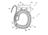
Images










Classifications
-
- A—HUMAN NECESSITIES
- A61—MEDICAL OR VETERINARY SCIENCE; HYGIENE
- A61B—DIAGNOSIS; SURGERY; IDENTIFICATION
- A61B5/00—Measuring for diagnostic purposes; Identification of persons
- A61B5/68—Arrangements of detecting, measuring or recording means, e.g. sensors, in relation to patient
- A61B5/6801—Arrangements of detecting, measuring or recording means, e.g. sensors, in relation to patient specially adapted to be attached to or worn on the body surface
- A61B5/6802—Sensor mounted on worn items
- A61B5/681—Wristwatch-type devices
-
- A—HUMAN NECESSITIES
- A61—MEDICAL OR VETERINARY SCIENCE; HYGIENE
- A61B—DIAGNOSIS; SURGERY; IDENTIFICATION
- A61B5/00—Measuring for diagnostic purposes; Identification of persons
- A61B5/02—Detecting, measuring or recording for evaluating the cardiovascular system, e.g. pulse, heart rate, blood pressure or blood flow
- A61B5/021—Measuring pressure in heart or blood vessels
- A61B5/02141—Details of apparatus construction, e.g. pump units or housings therefor, cuff pressurising systems, arrangements of fluid conduits or circuits
-
- A—HUMAN NECESSITIES
- A61—MEDICAL OR VETERINARY SCIENCE; HYGIENE
- A61B—DIAGNOSIS; SURGERY; IDENTIFICATION
- A61B5/00—Measuring for diagnostic purposes; Identification of persons
- A61B5/02—Detecting, measuring or recording for evaluating the cardiovascular system, e.g. pulse, heart rate, blood pressure or blood flow
- A61B5/021—Measuring pressure in heart or blood vessels
- A61B5/022—Measuring pressure in heart or blood vessels by applying pressure to close blood vessels, e.g. against the skin; Ophthalmodynamometers
Definitions
- the present invention relates to a blood pressure measurement device that measures blood pressure.
- the blood pressure measuring device measures the blood pressure by detecting the vibration of the arterial wall by inflating and contracting a cuff wrapped around the upper arm or wrist of the living body and detecting the pressure of the cuff with a pressure sensor.
- a blood pressure measuring device for example, a so-called integrated type in which a cuff and a device body that supplies fluid to the cuff are integrally configured is known.
- a blood pressure measuring device has a problem that the accuracy of the measured blood pressure measurement result decreases when the cuff has wrinkles, folds, or the like.
- the cuff is required to be inflated in the direction in which the blood vessel is closed and the cuff is closely attached to the wrist.
- a blood pressure measuring device is known to use a curler between the belt and the cuff in order to bring the inflated cuff into close contact with the upper arm or wrist.
- the cuff is integrally bonded to the curler by adhering and fixing the cuff to the curler with an adhesive layer such as a double-sided tape.
- the center side of the cuff inflates from the edge side.
- the stress applied to the adhesive layer that bonds the cuff to the curler is concentrated on the edge side of the cuff. Therefore, stress is generated in the adhesive layer so that the cuff peels from the curler from the edge side of the cuff. Therefore, when the cuff repeatedly expands and contracts, the cuff may peel off from the curler.
- the width of the curler and the cuff becomes smaller, the area where the cuff and the curler adhere to each other becomes smaller, so that the cuff becomes more easily peeled from the curler. Therefore, increasing the width of the cuff and the curler may improve the joint strength of the curl and the cuff.
- an object of the present invention is to provide a blood pressure measurement device capable of improving the bonding strength between the cuff and the curler.
- a curler that is curved along the circumferential direction of a part to which a living body is attached, is formed by welding two sheet members and an edge portion of the two sheet portions, and a plurality of insertion holes are formed.
- a bag-shaped structure having a welded portion including, expanded by a fluid, disposed on the inner peripheral surface of the curler, and abutting on the living body side surface of the welded portion, and inserted into the plurality of insertion holes. And a joining means for joining the welded portion to the curler.
- the fluid includes liquid and air.
- the bag-shaped structure is wrapped around the upper arm or wrist of a living body when measuring blood pressure, and is expanded by being supplied with fluid to form a cuff.
- the joining means is a member that mechanically joins two members, and includes, for example, a caulking protrusion, a rivet, a sewing thread, and the like.
- the bag-shaped structure can be mechanically joined to the curler, the bag-shaped structure can be firmly joined to the curler. Therefore, the blood pressure measurement device can improve the bonding strength between the cuff and the curler.
- the bag-like structure is formed by welding two sheet members, and by providing an insertion hole for inserting the joining means in the welding portion where the two sheet members are welded, the welding portion is formed. It can be used as a joining fee. With this configuration, it is not necessary to separately provide a joining margin for joining the bag-shaped structure to the curler, and the blood pressure measurement device can be downsized.
- the joining unit is integrally formed with at least one of the frame-shaped base material and the curler or the base material that are arranged so as to face the welded portion, and the plurality of insertions are performed.
- Blood pressure measurement having a plurality of protrusions inserted into holes and a plurality of holes to be joined, into which the plurality of protrusions are inserted and which are formed on at least one of the base material or the curler, and which are joined.
- a device is provided.
- the curler and the base material are provided with the plurality of protrusions inserted into the insertion hole and the plurality of holes to be joined to which the plurality of protrusions are joined. Therefore, the bag-shaped structure can be mechanically joined to the curler by disposing the bag-shaped structure between the curler and the base material and joining the curler and the base material by the projections and the holes to be joined. Further, since the base material has a frame-like shape that is arranged so as to face the welded portion, it does not hinder the expansion of the bag-shaped structure.
- a blood pressure measurement device in which the plurality of protrusions are formed of a thermoplastic resin material and caulking is performed by heat.
- the plurality of protrusions can be caulked by heat, which facilitates the caulking of the protrusions.
- a blood pressure measurement device in which the curler and the base material are formed of a thermoplastic resin material.
- the curler and the base material are formed of the thermoplastic resin material
- the curler or the base material provided with the plurality of holes to be joined is also the protrusion. It is also heated.
- the joint strength between the base material and the curlers is improved, and as a result, the joint strength between the bag-shaped structure and the curler arranged between the base material and the curlers is improved.
- the blood pressure measurement device in which the plurality of protrusions, the curler and the base material are formed of the same material, and the plurality of protrusions are welded to the curler or the base material by heat.
- the same type of material means two materials that have good compatibility in heat welding and have the same or close softening temperature.
- Compatibility means the degree to which resin materials softened or melted during welding are mixed, and compatibility means that the degree to which resin materials softened or melted during welding is mixed is preferable, that is, required. It means that bonding can be performed with the bonding strength.
- the curlers or the base material provided with the protrusions and the holes to be joined can be preferably joined by heat welding, so that the base material and the curlers can be firmly bonded.
- the blood pressure measurement device wherein the curler and the base material are integrally molded and have a hinge portion that connects the curler and the base material.
- the curler and the base material are connected to each other through the hinge portion and can be integrally molded by molding, it is possible to easily manufacture and reduce the number of parts.
- the curler and the base material can be opposed to each other by rotating the curler and the base material around the hinge portion, it is not necessary to align the plurality of protrusions and the plurality of holes to be joined, and the curler and the base material can be easily arranged. The material can be assembled.
- a blood pressure measuring device in which the bag-shaped structure is elongated in one direction and the base material is divided into a plurality in the longitudinal direction.
- the base material can be easily arranged in the welded portion of the bag-shaped structure even when a plurality of bag-shaped structures are stacked. be able to.
- the bag-shaped structures are stacked in a plurality, the plurality of insertion holes are provided in the welded portion of the bag-shaped structure facing the curler, the plurality of protrusions, There is provided a blood pressure measurement device provided in the base material, and the plurality of holes to be joined are provided in the curler.
- the protrusion is caulked on the outer surface side of the curler. For this reason, only the base material is arranged between the adjacent bag-shaped structures, and the ends of the projections to be crimped are not arranged. Since the portion to be swaged is not located between the adjacent bag-shaped structures, the portion to be swaged does not interfere with the bag-shaped structure when the bag-shaped structure is expanded and contracted. Moreover, since the thickness of the plurality of bag-shaped structures is only added to the thickness of the base material, it is possible to prevent the thickness of the cuff formed of the plurality of bag-shaped structures from increasing.
- the present invention can provide a blood pressure measurement device capable of improving the bonding strength between the cuff and the curler.
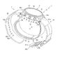
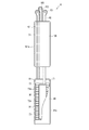
- FIG. 1 is a perspective view showing the configuration of the blood pressure measurement device according to the first embodiment of the present invention.
- FIG. 2 is a perspective view showing the configuration of the blood pressure measurement device.
- FIG. 3 is an exploded perspective view of the configuration of the blood pressure measurement device.
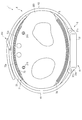
- FIG. 4 is an explanatory diagram showing a state in which the blood pressure measurement device is worn on the wrist.
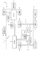
- FIG. 5 is a block diagram showing the configuration of the blood pressure measurement device.
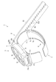
- FIG. 6 is a perspective view showing a configuration of a device body and a curler of the blood pressure measurement device.
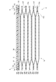
- FIG. 7 is a plan view showing the configuration of the cuff structure of the blood pressure measurement device.
- FIG. 8 is a plan view showing another configuration of the cuff structure of the blood pressure measurement device.
- FIG. 1 is a perspective view showing the configuration of the blood pressure measurement device according to the first embodiment of the present invention.
- FIG. 2 is a perspective view showing the configuration of the blood pressure measurement device.
- FIG. 3 is
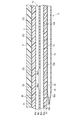
- FIG. 9 is sectional drawing which shows the structure of the belt, curlers, and cuff structure of the same blood pressure measuring device.
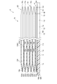
- FIG. 10 is a sectional view showing a configuration of a curler and a cuff structure of the blood pressure measurement device.
- FIG. 11 is a cross-sectional view showing a configuration of a curler and a cuff structure of the blood pressure measurement device.
- FIG. 12 is a cross-sectional view showing a configuration of a curler and a cuff structure of the blood pressure measurement device.
- FIG. 13 is an explanatory diagram showing a configuration when the cuff structure is inflated with the blood pressure measurement device worn on the wrist.
- FIG. 10 is a sectional view showing a configuration of a curler and a cuff structure of the blood pressure measurement device.
- FIG. 11 is a cross-sectional view showing a configuration of a curler and a cuff structure of the blood pressure measurement device.
- FIG. 12 is a cross-sectional
- FIG. 14 is a cross-sectional view showing the configuration when the cuff structure is inflated with the blood pressure measurement device worn on the wrist.
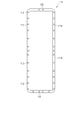
- FIG. 15 is a plan view showing the configuration of the base material of the blood pressure measurement device.
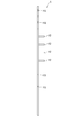
- FIG. 16 is a side view which shows the structure of the same base material.
- FIG. 17 is a plan view showing a configuration of an air bag of the blood pressure measurement device.
- FIG. 18 is a plan view showing a configuration of a curler of the blood pressure measurement device.
- FIG. 19 is a side view showing the configuration of the curler.
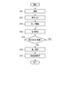
- FIG. 20 is a flow chart showing an example of use of the blood pressure measurement device.
- FIG. 21 is a perspective view showing an example of wearing the blood pressure measurement device on the wrist.
- FIG. 21 is a perspective view showing an example of wearing the blood pressure measurement device on the wrist.
- FIG. 22 is a perspective view showing an example of wearing the blood pressure measurement device on the wrist.
- FIG. 23 is a perspective view showing an example of mounting the blood pressure measuring device on the wrist.
- FIG. 24 is an explanatory diagram showing an example of joining the curler and the cuff structure in the blood pressure measurement device.
- FIG. 25 is a cross-sectional view showing a configuration of a curler and a cuff structure according to a modified example of the present invention.
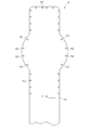
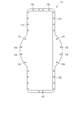
- FIG. 26 is a plan view showing the structure of a base material according to a modified example of the present invention.
- FIG. 27 is a plan view showing the configuration of the curler according to the modification of the present invention.
- FIG. 28 is a side view showing the configuration of the curler according to the modification of the present invention.
- FIG. 29 is a plan view showing the structure of a base material according to a modification of the present invention.
- FIG. 30 is a perspective view showing the configuration of the blood pressure measurement device according to the second embodiment of the present invention.
- FIG. 31 is a cross-sectional view showing the configuration of the blood pressure measurement device.
- FIG. 32 is a block diagram showing a configuration of the blood pressure measurement device.
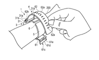
- FIG. 1 is a perspective view showing the configuration of the blood pressure measurement device 1 according to the first embodiment of the present invention with the belt 4 closed.
- FIG. 2 is a perspective view showing the configuration of the blood pressure measurement device 1 with the belt 4 opened.
- FIG. 3 is an exploded perspective view showing the configuration of the blood pressure measurement device 1.
- FIG. 4 is an explanatory view showing a cross section of a state in which the blood pressure measurement device 1 is attached to the wrist 200.
- FIG. 5 is a block diagram showing the configuration of the blood pressure measurement device 1.
- FIG. 6 is a perspective view showing the configurations of the device body 3 and the curler 5 of the blood pressure measurement device 1.
- FIG. 7 is a plan view showing the configuration of the cuff structure 6 of the blood pressure measurement device 1.
- FIG. 8 is a plan view showing another configuration of the cuff structure 6 of the blood pressure measurement device 1.
- FIG. 9 is a cross-sectional view showing the configuration of the belt 4, the curler 5 and the cuff structure 6 on the side of the flat cuff 71 of the blood pressure measurement device 1 taken along the line IX-IX in FIG. 7.
- FIG. 10 is a cross-sectional view showing the curler 5 and the cuff structure 6 of the blood pressure measurement device 1 with some parts omitted.
- FIG. 11 is a cross-sectional view showing the configurations of the curler 5 and the cuff structure 6 on the instep cuff 74 side of the blood pressure measurement device 1.
- FIG. 9 is a cross-sectional view showing the configuration of the belt 4, the curler 5 and the cuff structure 6 on the side of the flat cuff 71 of the blood pressure measurement device 1 taken along the line IX-IX in FIG. 7.
- FIG. 10 is a cross-sectional view showing the curler 5 and the
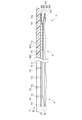
- FIG. 12 is a cross-sectional view showing the configuration of the cuff structure 6 in which the curler 5 and the tube 92 are omitted on the instep cuff 74 side of the blood pressure measurement device 1 taken along the line XI-XI in FIG. 7.
- FIG. 13 is an explanatory diagram showing the configuration when the cuff structure 6 is inflated with the blood pressure measurement device 1 attached to the wrist 200.
- FIG. 14 is a cross-sectional view taken along the line XIII-XIII in FIG. 7 showing the configuration when the cuff structure 6 is inflated with the blood pressure measurement device 1 attached to the wrist.
- 15 and 16 are a plan view and a side view showing the configuration of the base material of the blood pressure measurement device 1.
- FIG. 17 is a plan view showing the configuration of the air bags 81 and 101 of the blood pressure measurement device 1.
- 18 and 19 are a plan view and a side view showing the configuration of the curler 5 of the blood pressure measurement device 1.
- the blood pressure measurement device 1 is an electronic blood pressure measurement device worn on a living body. This embodiment will be described using an electronic blood pressure measurement device having a form of a wearable device that is worn on the wrist 200 of a living body.
- a blood pressure measurement device 1 includes a device body 3, a belt 4 for fixing the device body 3 to a wrist, a curler 5 arranged between the belt 4 and the wrist, and a flat cuff 71.
- a cuff structure 6 having a sensing cuff 73 and an instep cuff 74, a fluid circuit 7 for fluidly connecting the device body 3 and the cuff structure 6, and a joining means 8 for joining the curler 5 and the cuff structure 6. Is equipped with.
- the device body 3 includes, for example, a case 11, a display unit 12, an operation unit 13, a pump 14, a flow path unit 15, an opening / closing valve 16, and a pressure sensor 17.
- a power supply unit 18, a vibration motor 19, and a control board 20 are provided.
- the device body 3 supplies a fluid to the cuff structure 6 by the pump 14, the opening / closing valve 16, the pressure sensor 17, the control board 20, and the like.
- the case 11 includes an outer case 31, a windshield 32 that covers an upper opening of the outer case 31, a base portion 33 provided below the inside of the outer case 31, and a lower part of the outer case 31. And a back cover 35 that covers the.
- the outer case 31 is formed in a cylindrical shape.
- the outer case 31 includes a pair of lugs 31a provided at symmetrical positions in the circumferential direction of the outer peripheral surface, and spring rods 31b provided between the pair of lugs 31a.
- the windshield 32 is, for example, a circular glass plate.
- the base 33 holds the display unit 12, the operation unit 13, the pump 14, the opening / closing valve 16, the pressure sensor 17, the power supply unit 18, the vibration motor 19, and the control board 20.
- the base portion 33 constitutes, for example, a part of the flow passage portion 15 that fluidly connects the pump 14 and the cuff structure body 6.
- the back cover 35 covers the living body side end of the outer case 31.
- the back cover 35 is fixed to the living body side end of the outer case 31 or the base 33 by, for example, four screws 35a.
- the display unit 12 is arranged on the base 33 of the outer case 31 and directly below the windshield 32.
- the display unit 12 is electrically connected to the control board 20.
- the display unit 12 is, for example, a liquid crystal display or an organic electroluminescence display.
- the display unit 12 displays various types of information including blood pressure values such as date and time, systolic blood pressure and diastolic blood pressure, and measurement results such as heart rate.
- the operation unit 13 is configured to be able to input a command from the user.
- the operation unit 13 includes a plurality of buttons 41 provided on the case 11, a sensor 42 that detects an operation of the buttons 41, and a touch panel 43 provided on the display unit 12 or the windshield 32. , Is provided.
- the operation unit 13 is operated by a user to convert a command into an electric signal.
- the sensor 42 and the touch panel 43 are electrically connected to the control board 20 and output an electric signal to the control board 20.
- the plurality of buttons 41 are provided, for example, three.
- the button 41 is supported by the base 33 and protrudes from the outer peripheral surface of the outer case 31.
- the plurality of buttons 41 and the plurality of sensors 42 are supported by the base 33.
- the touch panel 43 is provided integrally with the windshield 32, for example.
- the pump 14 is, for example, a piezoelectric pump.
- the pump 14 compresses air and supplies the compressed air to the cuff structure 6 via the flow path portion 15.
- the pump 14 is electrically connected to the control board 20.
- the flow path portion 15 constitutes a flow path from the pump 14 to the flat cuff 71 and the instep cuff 74, and a flow path from the pump 14 to the sensing cuff 73.
- the flow path portion 15 constitutes a flow path that connects the flat cuff 71 and the instep cuff 74 to the atmosphere, and a flow path that connects the sensing cuff 73 to the atmosphere.
- the flow path portion 15 is an air flow path configured by a hollow portion provided in the base portion 33 and the like, a groove, a tube, and the like.
- the on-off valve 16 opens and closes a part of the flow path section 15. As shown in FIG. 5, for example, a plurality of on-off valves 16 are provided, and a combination of opening and closing of each on-off valve 16 connects the flow path from the pump 14 to the flat cuff 71 and the instep cuff 74, and from the pump 14 to the sensing cuff 73.
- the flow path, the flow path connecting the flat cuff 71 and the instep cuff 74 to the atmosphere, and the flow path connecting the sensing cuff 73 to the atmosphere are selectively opened and closed.
- two on-off valves 16 are used.
- the pressure sensor 17 detects the pressure of the flat cuff 71, the sensing cuff 73, and the instep cuff 74.
- the pressure sensor 17 is electrically connected to the control board 20.
- the pressure sensor 17 converts the detected pressure into an electric signal and outputs it to the control board 20.
- the pressure sensor 17 is provided in a flow path connecting the pump 14 to the flat cuff 71 and the instep cuff 74 and a flow path connecting the pump 14 to the sensing cuff 73.
- the power supply unit 18 is, for example, a secondary battery such as a lithium ion battery.
- the power supply unit 18 is electrically connected to the control board 20.
- the power supply unit 18 supplies power to the control board 20.
- control board 20 includes, for example, a board 51, an acceleration sensor 52, a communication unit 53, a storage unit 54, and a control unit 55.
- the control board 20 is configured by mounting the acceleration sensor 52, the communication section 53, the storage section 54, and the control section 55 on the board 51.
- the substrate 51 is fixed to the base 33 of the case 11 with screws or the like.
- the acceleration sensor 52 is, for example, a triaxial acceleration sensor.
- the acceleration sensor 52 outputs an acceleration signal representing accelerations of the device body 3 in three directions orthogonal to each other to the control unit 55.
- the acceleration sensor 52 is used to measure the activity amount of the living body wearing the blood pressure measurement device 1 from the detected acceleration.
- the communication unit 53 is configured to be capable of transmitting / receiving information to / from an external device by wireless or wired.
- the communication unit 53 transmits, for example, information controlled by the control unit 55 and information such as measured blood pressure value and pulse rate to an external device via a network, and software from the external device via the network.
- the update program or the like is received and sent to the control unit.
- the network is, for example, the Internet, but is not limited to this, and may be a network such as a LAN (Local Area Network) provided in a hospital, or a predetermined standard such as USB. It may be a direct communication with an external device using a cable having a terminal. Therefore, the communication unit 53 may be configured to include a plurality of wireless antennas, micro USB connectors, and the like.
- LAN Local Area Network
- USB Universal Serial Bus
- the storage unit 54 stores program data for controlling the blood pressure measurement device 1 and the fluid circuit 7, setting data for setting various functions of the blood pressure measurement device 1, blood pressure values and pulse rates based on the pressure measured by the pressure sensor 17. Calculated data for calculating is stored in advance.
- the storage unit 54 also stores information such as the measured blood pressure value and pulse.
- the control unit 55 is composed of a single CPU or a plurality of CPUs, and controls the operation of the entire blood pressure measurement device 1 and the operation of the fluid circuit 7.
- the control unit 55 is electrically connected to the display unit 12, the operation unit 13, the pump 14, the open / close valves 16 and the pressure sensors 17, and supplies electric power. Further, the control unit 55 controls the operations of the display unit 12, the pump 14, and the open / close valve 16 based on the electric signals output by the operation unit 13 and the pressure sensor 17.
- the control unit 55 has a main CPU (Central Processing Unit) 56 that controls the operation of the entire blood pressure measurement device 1 and a sub CPU 57 that controls the operation of the fluid circuit 7.
- the main CPU 56 obtains a measurement result such as a blood pressure value such as systolic blood pressure and diastolic blood pressure or a heart rate from the electric signal output from the pressure sensor 17, and outputs an image signal corresponding to the measurement result to the display unit 12.
- a measurement result such as a blood pressure value such as systolic blood pressure and diastolic blood pressure or a heart rate
- the sub CPU 57 drives the pump 14 and the open / close valve 16 to send compressed air to the flat cuff 71 and the sensing cuff 73. Further, the sub CPU 57 controls driving and stopping of the pump 14 and opening / closing of the open / close valve 16 based on the electric signal output from the pressure sensor 17. The sub CPU 57 controls the pump 14 and the opening / closing valve 16 to selectively send compressed air to the flat cuff 71 and the sensing cuff 73, and also selectively depressurize the flat cuff 71 and the sensing cuff 73.
- the belt 4 includes a first belt 61 provided on one pair of lugs 31a and a spring rod 31b, and a second belt 61 provided on the other pair of lugs 31a and a spring rod 31b. And a belt 62.
- the belt 4 is wrapped around the wrist 200 via the curler 5.
- the first belt 61 is called a so-called parent and is formed in a belt shape.
- the first belt 61 is provided at one end of the first belt 61 and is orthogonal to the longitudinal direction of the first belt 61, and the other end of the first belt 61 is orthogonal to the longitudinal direction of the first belt 61. It has two holes 61b and a buckle 61c provided in the second hole 61b.
- the first hole portion 61a has an inner diameter into which the spring rod 31b can be inserted and the first belt 61 can rotate with respect to the spring rod 31b. That is, the first belt 61 is rotatably held in the outer case 31 by being disposed between the pair of lugs 31a and by disposing the first hole portion 61a in the spring rod 31b.
- the second hole 61b is provided at the tip of the first belt 61.
- the buckle 61c has a rectangular frame-shaped frame 61d and a stick 61e rotatably attached to the frame 61d.
- One side of the frame-shaped body 61d, to which the stick 61e is attached, is inserted into the second hole portion 61b and is rotatably attached with respect to the first belt 61.
- the second belt 62 is a so-called sword tip, and is configured in a belt shape having a width that can be inserted into the frame-shaped body 61d. Further, the second belt 62 has a plurality of small holes 62a into which the sticks 61e are inserted.
- the second belt 62 has a third hole portion 62b that is provided at one end portion and that is orthogonal to the longitudinal direction of the second belt 62.
- the third hole portion 62b has an inner diameter into which the spring rod 31b can be inserted and the second belt 62 can rotate with respect to the spring rod 31b. That is, the second belt 62 is rotatably held in the outer case 31 by being disposed between the pair of lugs 31a and by disposing the third hole portion 62b in the spring rod 31b.
- the second belt 62 is inserted into the frame-shaped body 61d, and the rod 61e attached to the small hole 62a is inserted, whereby the first belt 61 and the second belt 62 are integrally connected, and the outer shell is formed. Together with the case 31, it becomes an annular shape that follows the circumferential direction of the wrist 200.
- the curler 5 is formed in a band shape that curves along the circumferential direction of the wrist.
- the curler 5 is formed such that one end and the other end are separated from each other.
- the outer surface of the curler 5 on one end side is fixed to the back cover 35 of the apparatus body 3.
- the curler 5 is arranged at a position where one end and the other end of the curler 5 project beyond the case back 35. Further, the curlers 5 are separated by a predetermined distance, and one end and the other end are adjacent to each other.
- the curler 5 is fixed to the living body side end of the outer case 31 or the base 33 together with the back cover 35 by using screws 35a or the like. Further, the curler 5 is fixed to the back cover 35 so that one end and the other end are located on one side of the wrist 200 when the blood pressure measurement device 1 is attached to the wrist 200.
- the curler 5 is, for example, a direction orthogonal to the circumferential direction of the wrist, in other words, the circumferential direction of the wrist 200 in a side view from the longitudinal direction of the wrist. It has a shape that curves along.
- the curler 5 extends from the device body 3 to the palm side of the wrist 200 through the back side of the wrist 200 and one side side of the wrist 200, and extends to the other side side of the wrist 200, for example. That is, the curler 5 is arranged along most of the circumferential direction of the wrist 200 by being curved along the circumferential direction of the wrist 200, and both ends thereof are separated by a predetermined distance.
- the curler 5 forms part of the structure of the joining means 8.
- the curler 5 has a plurality of holes to be joined 113, which will be described later, that form the joining means 8 on the outer peripheral edge thereof.
- the curler 5 has hardness having flexibility and shape retention.
- the flexibility means that the shape is deformed in the radial direction when the external force of the belt 4 is applied to the curler 5.
- flexibility means that, when the curler 5 is pressed by the belt 4, the curler 5 approaches the wrist, follows the shape of the wrist, or deforms the shape in a side view so as to follow the shape of the wrist.
- the shape-retaining property means that the curler 5 can maintain a preshaped shape when an external force is not applied.
- the outer shape retaining property means that in the present embodiment, the curler 5 can maintain a shape in which the curler 5 is curved along the circumferential direction of the wrist.
- the curler 5 has a cuff structure 6 arranged on the inner peripheral surface thereof, and holds the cuff structure 6 along the shape of the inner peripheral surface of the curler 5.
- the flat cuff 71 and the instep cuff 74 are arranged on the inner peripheral surface, and the flat cuff 71 and the instep cuff 74 are joined by the joining means 8.
- the curler 5 is made of a resin material.
- the curler 5 is formed of, for example, a thermoplastic resin material, specifically, polypropylene.
- the curler 5 is formed to have a thickness of, for example, about 1 mm.
- the cuff structure 6 includes a flat cuff (cuff) 71, a back plate 72, a sensing cuff 73, and an instep cuff (cuff) 74. ing.
- the cuff structure 6 is fixed to the curler 5.
- a flat cuff 71, a back plate 72 and a sensing cuff 73 are stacked and arranged on the curler 5, and an instep cuff 74 is arranged on the curler 5 while being separated from the flat cuff 71, the back plate 72 and the sensing cuff 73. To be done.
- a flat cuff 71, a back plate 72, a sensing cuff 73, and an instep cuff 74 are arranged on the inner surface of the curler 5.
- the cuff structure 6 is fixed to the inner surface on the palm side of the wrist 200 of the curler 5 by laminating the flat cuff 71, the back plate 72, and the sensing cuff 73 in this order from the inner surface of the curler 5 toward the living body.
- an instep cuff 74 is arranged on the inner surface of the wrist 200 of the curler 5 on the back side of the hand.
- Each member of the cuff structure 6 is fixed to a member adjacent in the stacking direction with a double-sided tape or an adhesive.
- the flat cuff 71 is a so-called pressing cuff.
- the flat cuff 71 is fluidly connected to the pump 14 via the flow path portion 15.
- the flat cuff 71 expands to press the back plate 72 and the sensing cuff 73 toward the living body.
- the flat cuff 71 includes a plurality of, for example, two layers of air bags 81, and a plurality of insertion holes 82 provided in the air bag 81 of the two layers of air bags 81 arranged on the curler 5 side.
- the air bag 81 is a bag-shaped structure, and in the present embodiment, since the blood pressure measurement device 1 is configured to use air by the pump 14, it will be described using the air bag, but other than air.
- the bag-shaped structure may be a fluid bag such as a liquid bag.
- the plurality of air bags 81 are stacked and fluidly communicate with each other in the stacking direction.
- the air bag 81 is formed in a rectangular shape that is long in one direction.
- the air bag 81 is configured by, for example, combining two sheet members 86 that are long in one direction and welding the edges by heat. That is, the air bladder 81 has the welded portion 81a in which the peripheral portions of the four sides are welded.
- the two-layer air bladder 81 includes a first sheet member 86a and a second sheet bladder 81 that constitutes the first sheet member 86a and the first-layer air bag 81 from the living body side.
- a sheet member 86b, a third sheet member 86c that is integrally bonded to the second sheet member 86b, and a fourth sheet member 86d that constitutes the third sheet member 86c and the second-layer air bag 81 are provided.
- the two-layer air bag 81 is integrally configured by joining the sheet members 86 of the adjacent air bags 81 by double-sided tape, adhesive bonding or welding.
- the first sheet member 86a and the second sheet member 86b form the air bag 81 by welding the peripheral portions of the four sides.
- the second sheet member 86b and the third sheet member 86c are arranged to face each other, and each has a plurality of openings 86b1 and 86c1 that fluidly connect the two air bags 81.
- the third sheet member 86c and the fourth sheet member 86d form the air bag 81 by welding the peripheral portions of the four sides.
- the welded portion 81a formed on the peripheral portions of the third sheet member 86c and the fourth sheet member 86d has a plurality of insertion holes 82.
- the fourth sheet member 86d is arranged on the curler 5 side.
- the plurality of insertion holes 82 are configured so that a part of the joining means 8 can be inserted, as shown in FIGS. 10, 14 and 17. Further, the plurality of insertion holes 82 face the plurality of bonded holes 113 of the curler 5 when the two-layer air bag 81 is arranged in the curler 5.
- the plurality of insertion holes 82 are provided at predetermined positions on the entire circumference of the peripheral portion of the welded portion 81a of the air bags 81, 101 arranged on the curler 5 side of the six-layer air bags 81, 101 of the air bags 81, 101. It is provided at intervals.
- the predetermined interval is, for example, an interval at which the air bladder 81 of the flat cuff 71 can be joined to the curler 5 with suitable strength, and, for example, the flat cuff 71, or between the flat cuff 71 and the curler 5, and the like.
- the intervals at which these flow paths and the like can be arranged are set appropriately. Further, the predetermined intervals are not limited to equal intervals.
- the back plate 72 is attached to the outer surface of the first sheet member 86a of the flat cuff 71 with an adhesive layer or a double-sided tape.
- the back plate 72 is formed of a resin material in a plate shape.
- the back plate 72 is made of polypropylene, for example, and is formed into a plate shape having a thickness of about 1 mm.
- the back plate 72 has a shape following property.
- the shape-following property refers to a function of allowing the back plate 72 to be deformed so as to follow the shape of the contacted portion of the wrist 200 to be arranged, and the back plate 72 faces the contacted portion of the wrist 200.
- the area of the wrist 200 is referred to, and the contact here includes both direct contact and indirect contact via the sensing cuff 73.
- the back plate 72 has a plurality of grooves 72a extending in a direction orthogonal to the longitudinal direction on both main surfaces of the back plate 72.
- a plurality of grooves 72a are provided on both main surfaces of the back plate 72, respectively.
- the plurality of grooves 72a provided on both main surfaces face each other in the thickness direction of the back plate 72.
- the plurality of grooves 72a are arranged at equal intervals in the longitudinal direction of the back plate 72.
- the back plate 72 follows the shape of the wrist 200. It deforms and has shape following properties that extend in the circumferential direction of the wrist.
- the back plate 72 is formed to have a length that covers the palm side of the wrist 200.
- the back plate 72 transmits the pressing force from the flat cuff 71 to the main surface of the sensing cuff 73 on the back plate 72 side along the shape of the wrist 200.
- the sensing cuff 73 is fixed to the main surface of the back plate 72 on the living body side.
- the sensing cuff 73 is in direct contact with the region of the wrist 200 where the artery 210 is present, as shown in FIGS. 9 and 14.
- the artery 210 is a radial artery and an ulnar artery.
- the sensing cuff 73 is formed in the same shape as the back plate 72 or in a shape smaller than the back plate 72 in the longitudinal direction and the width direction of the back plate 72.
- the sensing cuff 73 When the sensing cuff 73 is inflated, the sensing cuff 73 compresses the area where the palm side artery 210 of the wrist 200 is present.
- the sensing cuff 73 is pressed toward the living body through the back plate 72 by the expanded flat cuff 71.
- the sensing cuff 73 includes one air bag 91, a tube 92 communicating with the air bag 91, and a connecting portion 93 provided at the tip of the tube 92.
- the sensing cuff 73 has one main surface of the air bag 91 fixed to the back plate 72.
- the sensing cuff 73 is attached to the main surface of the back plate 72 on the living body side with a double-sided tape, an adhesive layer, or the like.
- the air bag 91 is a bag-shaped structure, and in the present embodiment, since the blood pressure measurement device 1 has a configuration in which air is used by the pump 14, it will be described using the air bag, but other than air.
- the bag-shaped structure may be a liquid bag or the like.
- the air bag 91 is formed in a rectangular shape that is long in one direction.
- the air bag 91 is configured by, for example, combining two sheet members 96 that are long in one direction and welding the edges by heat.
- the air bag 91 includes a fifth sheet member 96a and a sixth sheet member 96b from the living body side.
- the tube 92 that is fluidly continuous with the internal space of the air bag 91 is arranged on one side of the fifth sheet member 96a and the sixth sheet member 96b, and is welded. Fixed.
- the peripheral portions of the four sides are welded in a state where the tube 92 is arranged between the fifth sheet member 96a and the sixth sheet member 96b to form the air bag 91.
- the tube 92 is integrally welded.
- the tube 92 is provided at one end of the air bag 91 in the longitudinal direction.
- the tube 92 is provided at the end of the air bag 91 close to the apparatus body 3.
- the tube 92 has a connecting portion 93 at its tip.
- the tube 92 is connected to the flow path portion 15 and constitutes a flow path between the apparatus body 3 and the air bag 91.
- the connection part 93 is connected to the flow path part 15.
- the connecting portion 93 is, for example, a nipple.
- the instep cuff 74 is a so-called pulling cuff.
- the instep cuff 74 is fluidly connected to the pump 14 via the flow path portion 15.
- the back cuff 74 pushes the curler 5 so as to be separated from the wrist 200 by being inflated, thereby pulling the belt 4 and the curler 5 toward the back side of the wrist 200.
- the instep cuff 74 includes a plurality of, for example, six layers of air bags 101, a tube 102 that communicates with the air bags 101, a connecting portion 103 provided at the tip of the tube 102, and a curler 5 of the six layers of air bags 101.
- a plurality of insertion holes 104 provided in the air bag 101 disposed on the side.
- the instep cuff 74 has an inflated thickness in the inflation direction, in the present embodiment, a direction in which the curler 5 and the wrist 200 face each other, and an inflated thickness in the inflation direction of the flat cuff 71, and sensing. It is configured to be thicker than the thickness of the cuff 73 in the inflating direction. That is, the air bag 101 of the instep cuff 74 has a layered structure larger than the air bag 81 of the flat cuff 71 and the air bag 91 of the sensing cuff 73, and has a thickness when inflated from the curler 5 toward the wrist 200. It is thicker than the flat cuff 71 and the sensing cuff 73.
- the air bag 101 is a bag-shaped structure, and in the present embodiment, since the blood pressure measurement device 1 has a configuration in which air is used by the pump 14, it will be described using an air bag, but other than air.
- the bag-shaped structure may be a fluid bag such as a liquid bag.
- the plurality of air bags 101 are stacked and fluidly communicate with each other in the stacking direction.
- the air bag 101 is formed in a rectangular shape that is long in one direction.
- the air bag 101 is configured by, for example, combining two sheet members 106 that are long in one direction and welding the edges by heat. That is, the air bag 101 has a welded portion 101a in which the peripheral portions of the four sides are welded.
- the six-layer air bag 101 includes a seventh sheet member 106a, an eighth sheet member 106b, a ninth sheet member 106c, and a tenth sheet from the living body side.
- Member 106d eleventh sheet member 106e, twelfth sheet member 106f, thirteenth sheet member 106g, fourteenth sheet member 106h, fifteenth sheet member 106i, sixteenth sheet member 106j, and seventeenth sheet member.
- 106k and the 18th sheet member 106l Note that the six-layer air bag 101 is integrally configured by joining the sheet members 106 of the adjacent air bags 101 by double-sided tape, adhesive bonding or welding.
- the seventh sheet member 106a and the eighth sheet member 106b form the air bag 101 of the first layer by welding the peripheral portions of the four sides.
- the eighth sheet member 106b and the ninth sheet member 106c are arranged facing each other and are integrally bonded.
- the eighth sheet member 106b and the ninth sheet member 106c have a plurality of openings 106b1 and 106c1 that fluidly connect the adjacent air bags 101.
- the ninth sheet member 106c and the tenth sheet member 106d form the air bag 101 of the second layer by welding the peripheral portions of the four sides.
- the tenth sheet member 106d and the eleventh sheet member 106e are arranged facing each other and are integrally bonded.
- the tenth sheet member 106d and the eleventh sheet member 106e have a plurality of openings 106d1 and 106e1 that fluidly connect the adjacent air bags 101.
- the eleventh sheet member 106e and the twelfth sheet member 106f constitute the air bag 101 of the third layer by welding the peripheral portions of the four sides.
- the twelfth sheet member 106f and the thirteenth sheet member 106g are arranged facing each other and are integrally bonded.
- the twelfth sheet member 106f and the thirteenth sheet member 106g have a plurality of openings 106f1 and 106g1 for fluidly connecting the adjacent air bags 101.
- the thirteenth sheet member 106g and the fourteenth sheet member 106h form the air bag 101 of the fourth layer by welding the peripheral portions of the four sides.
- the 14th sheet member 106h and the 15th sheet member 106i are arranged so as to face each other and are integrally bonded.
- the fourteenth sheet member 106h and the fifteenth sheet member 106i have a plurality of openings 106h1 and 106i1 for fluidly connecting the adjacent air bags 101.
- the fifteenth sheet member 106i and the sixteenth sheet member 106j form the air bag 101 of the fifth layer by welding the peripheral portions of the four sides.
- the 16th sheet member 106j and the 17th sheet member 106k are arranged so as to face each other and are integrally bonded.
- the sixteenth sheet member 106j and the seventeenth sheet member 106k have a plurality of openings 106j1 and 106k1 for fluidly connecting the adjacent air bags 101.
- the seventeenth sheet member 106k and the eighteenth sheet member 106l have their peripheral portions welded in a rectangular frame shape to form the sixth-layer air bag 101.
- the welded portion 101a formed on the peripheral portions of the seventeenth sheet member 106k and the eighteenth sheet member 106l has a plurality of insertion holes 82.
- the eighteenth sheet member 106l is arranged on the curler 5 side.
- a tube 102 that is fluidly continuous with the internal space of the air bag 101 is arranged on one side of the seventeenth sheet member 106k and the eighteenth sheet member 106l, and is fixed by welding.
- the seventeenth sheet member 106k and the eighteenth sheet member 106l are welded at their peripheral portions in a rectangular frame shape while the tube 102 is arranged between the seventeenth sheet member 106k and the eighteenth sheet member 106l to form the air bag 101.
- the tube 102 is integrally welded.
- such a sixth layer air bag 101 is configured integrally with the second layer air bag 81 of the flat cuff 71. That is, the seventeenth sheet member 106k is integrally formed with the third sheet member 86c, and the eighteenth sheet member 106l is integrally formed with the fourth sheet member 86d.
- the third sheet member 86c and the seventeenth sheet member 106k form a rectangular sheet member that is long in one direction
- the eighteenth sheet member 106l and the fourth sheet member 86d are rectangular sheets that are long in one direction.
- a shaped sheet member is configured.
- these sheet members are overlapped with each other, and one end portion side is formed into a rectangular frame shape and is welded except a part of one side on the other end portion side.
- the air bag 81 of the second layer of the flat cuff 71 is configured.
- the other end has a rectangular frame shape, and is welded except for a part of one side on one end to form the air bag 101 of the sixth layer of the instep cuff 74.
- the second-layer air bag 81 and the sixth-layer air bag 101 are fluidly continuous because part of one side facing each other is not welded.
- the tube 102 is connected to one air bag 101 out of the six layers of air bags 101 and is provided at one end of the air bag 101 in the longitudinal direction.
- the tube 102 is provided on the curler 5 side of the six-layer air bag 101 and at an end portion near the apparatus body 3.
- the tube 102 has a connecting portion 103 at the tip.
- the tube 102 constitutes a flow path between the device body 3 and the air bag 101 in the fluid circuit 7.
- the connection portion 103 is, for example, a nipple.
- the instep cuff 74 is partially configured integrally with the flat cuff 71 and is fluidly continuous with the flat cuff 71.
- the present invention is not limited to this.
- the instep cuff 74 may be configured separately from the flat cuff 71 and may be fluidly discontinuous with the flat cuff 71.
- the flat cuff 71 is further provided with a tube and a connecting portion similarly to the sensing cuff 73 and the instep cuff 74, and also in the fluid circuit 7, the fluid is supplied to the flat cuff 71.
- the flow path, the check valve, and the pressure sensor may be connected.
- the plurality of insertion holes 104 are configured so that a part of the joining means 8 can be inserted. Further, the plurality of insertion holes 104 face the plurality of bonded holes 113 of the curler 5 when the six-layer air bag 101 is arranged in the curler 5.
- the plurality of insertion holes 104 are provided at predetermined intervals around the entire periphery of the welded portion 101a of the air bag 101 disposed on the curler 5 side of the six-layer air bag 101 of the air bag 101. .
- the predetermined interval is, for example, an interval at which the instep cuff 74 can be joined to the curler 5 with a suitable strength, and, for example, the instep cuff 74 or the flat cuff between the instep cuff 74 and the curler 5.
- a flow path of air to 71, a flow path of air to the sensing cuff 73, and the like are provided, they are intervals at which these flow paths and the like can be arranged and are set appropriately. Further, the predetermined intervals are not limited to equal intervals.
- Each sheet member 86, 96, 106 forming the flat cuff 71, the sensing cuff 73, and the instep cuff 74 is made of a thermoplastic resin material.
- the thermoplastic resin material is a thermoplastic elastomer.
- thermoplastic resin material forming the sheet members 86, 96, 106 examples include thermoplastic polyurethane resin (Thermoplastic Poly Urethane, hereinafter referred to as TPU), vinyl chloride resin (PolyVinyl Chloride), ethylene vinyl acetate resin (Ethylene- VinylAcetate), thermoplastic polystyrene resin (Thermoplastic PolyStyrene), thermoplastic polyolefin resin (Thermoplastic PolyOlefin), thermoplastic polyester resin (ThermoPlastic Polyester), and thermoplastic polyamide resin (Thermoplastic PolyAmide) can be used.
- TPU thermoplastic polyurethane resin
- TPU thermoplastic Polyurethane resin
- Vinyl Chloride PolyVinyl Chloride
- ethylene vinyl acetate resin Ethylene- VinylAcetate
- thermoplastic polystyrene resin Thermoplastic PolyStyrene
- thermoplastic polyolefin resin Thermoplastic PolyOlefin
- a molding method such as T-die extrusion molding or injection molding is used.
- the sheet members 86, 96, 106 are molded by each molding method, then sized to a predetermined shape, and the sized pieces are joined by welding or the like to form the bag-shaped structures 81, 91, 101.
- a welding method a high-frequency welder or laser welding is used.
- the fluid circuit 7 is composed of a case 11, a pump 14, a flow path portion 15, an opening / closing valve 16, a pressure sensor 17, a flat cuff 71, a sensing cuff 73, and an instep cuff 74.
- the two on-off valves 16 used in the fluid circuit 7 are a first on-off valve 16A and a second on-off valve 16B, and the two pressure sensors 17 are a first pressure sensor 17A and a second pressure sensor 17B. A specific example will be described.
- the fluid circuit 7 is configured by, for example, a first flow path 7a that connects the flat cuff 71 and the instep cuff 74 from the pump 14 and a midway portion of the first flow path 7a.
- the pump 14 includes a second flow path 7b that connects the sensing cuff 73 and a third flow path 7c that connects the first flow path 7a and the atmosphere.
- the first flow path 7a includes a first pressure sensor 17A.
- a first opening / closing valve 16A is provided between the first flow path 7a and the second flow path 7b.
- the second flow path 7b includes a second pressure sensor 17B.
- a second opening / closing valve 16B is provided between the first flow path 7a and the third flow path 7c.
- the first opening / closing valve 16A and the second opening / closing valve 16B are closed so that only the first flow path 7a is connected to the pump 14, and the pump 14 and the flat cuff 71 are fluidly connected.
- the first opening / closing valve 16A is opened and the second opening / closing valve 16B is closed, so that the first flow path 7a and the second flow path 7b are connected, and the pump 14 and the instep cuff 74 and the instep cuff 74 are connected.
- the flat cuff 71, the pump 14 and the sensing cuff 73 are fluidly connected.
- the joining means 8 makes contact with the welded portions 81a of the air bags 81, 101 arranged adjacent to the curler 5, and the surfaces of the welded portions 81a, 101a on the wrist 200 side, and has a partial configuration of the welded portion 81a. , 101a.
- the joining means 8 joins the air bags 81 and 101 to the curler 5.
- the joining means 8 includes a base material 111, a plurality of protrusions 112 provided on at least one of the curler 5 and the base material 111, and the base material 111 and the curler 5. And a plurality of holes to be joined 113 provided on at least one side.
- description will be given below by using an example in which the plurality of protrusions 112 are provided on the base material 111 and the plurality of bonded holes 113 are provided on the curler 5.
- the base material 111 is provided on the flat cuff 71 and the instep cuff 74, respectively.
- the base material 111 is in the form of a thin plate and has a rectangular frame shape that is substantially the same as the surface shape of the welded portions 81 a and 101 a of the air bags 81 and 101.
- the flat cuff 71 and the instep cuff 74 are integrally connected, only one base material 111 may be provided. That is, when the flat cuff 71 and the instep cuff 74 are integrally continuous, the welded portions 81a and 101a of the air bags 81 and 101 forming the curler 5 side of the flat cuff 71 and the instep cuff 74 are integrally combined.
- the shape may be a rectangular frame having substantially the same shape as the surface shape.
- the base material 111 abuts on the surface of the welded portions 81a, 101a of the air bags 81, 101 adjacent to the curler 5 on the wrist 200 side.
- the plurality of protrusions 112 are provided on the surfaces of the welded portions 81a, 101a of the air bags 81, 101 adjacent to the curler 5 of the base material 111 that are in contact with the surfaces on the wrist 200 side.
- the plurality of protrusions 112 are provided in the base material 111 in the same arrangement as the plurality of insertion holes 82, 104 provided in the welded portions 81a, 101a of the air bags 81, 101.
- the plurality of protrusions 112 are integrally formed on the base material 111 by resin molding.
- the height of the projection 112 from the base material 111 is set higher than the sum of the thicknesses of the two sheet members 86 and 106 and the curler 5.
- the base material 111 and the plurality of projections 112 are formed of a thermoplastic resin material, for example, the same material as the curler 5.
- the base material 111 and the plurality of protrusions 112 are made of polypropylene.
- the plurality of holes 113 to be joined are provided in the portion of the curler 5 where the air bags 81 and 101 are provided, as shown in FIGS. 12, 18 and 19.
- the plurality of holes to be joined 113 are provided in the curler 5 in the same arrangement as the plurality of insertion holes 82 and 104 provided in the welded portions 81a and 101a of the air bags 81 and 101.
- FIG. 20 is a flowchart showing an example of blood pressure measurement using the blood pressure measurement device 1, and shows both the user's operation and the operation of the control unit 55.
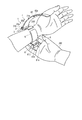
- 21 to 23 show an example in which the user wears the blood pressure measurement device 1 on the wrist 200.
- the user wears the blood pressure measurement device 1 on the wrist 200 (step ST1).
- the user inserts one of the wrists 200 into the curler 5, as shown in FIG.
- the sensing cuff 73 is arranged in the region where the palm side artery 210 of the wrist 200 exists.
- the device body 3 and the back cuff 74 are arranged on the back side of the wrist 200.
- the user passes the second belt 62 through the frame-shaped body 61d of the buckle 61c of the first belt 61 with the hand opposite to the hand on which the blood pressure measurement device 1 is placed.
- the user pulls the second belt 62 to bring the member on the inner peripheral surface side of the curler 5, that is, the cuff structure 6 into close contact with the wrist 200, and inserts the rod 61e attached to the small hole 62a.
- the first belt 61 and the second belt 62 are connected, and the blood pressure measurement device 1 is worn on the wrist 200.
- the user operates the operation unit 13 to input a command corresponding to the start of blood pressure measurement.
- the operation unit 13 that has performed the input operation of the command outputs an electric signal corresponding to the start of measurement to the control unit 55 (step ST2).
- the control unit 55 receives the electric signal, for example, the first opening / closing valve 16A is opened, the second opening / closing valve 16B is closed, the pump 14 is driven, and the first passage 7a and the second passage 7b are passed through.
- the compressed air is supplied to the flat cuff 71, the sensing cuff 73, and the instep cuff 74 (step ST3).
- the flat cuff 71, the sensing cuff 73, and the instep cuff 74 start to inflate.
- the first pressure sensor 17A and the second pressure sensor 17B detect the pressures of the flat cuff 71, the sensing cuff 73, and the instep cuff 74, respectively, and output an electric signal corresponding to this pressure to the control unit 55 (step ST4).
- the control unit 55 determines whether the pressure in the internal space of the flat cuff 71, the sensing cuff 73 and the instep cuff 74 has reached a predetermined pressure for blood pressure measurement based on the received electric signal (step ST5). ).
- the control unit 55 turns on the first opening / closing valve 16A. Closed, and compressed air is supplied through the first flow path 7a.
- the control unit 55 stops the driving of the pump 14 (YES in step ST5). At this time, as shown in FIGS. 13 and 14, the flat cuff 71 and the instep cuff 74 are sufficiently inflated, and the inflated flat cuff 71 presses the back plate 72.
- the instep cuff 74 presses the curler 5 in the direction away from the wrist 200, the belt 4, the curler 5 and the device body 3 move in the direction away from the wrist 200, and as a result, the flat cuff 71, The back plate 72 and the sensing cuff 73 are pulled toward the wrist 200.
- the belt 4 and the device body 3 move in the direction away from the wrist 200 due to the expansion of the instep cuff 74, the belt 4 and the curler 5 move toward both sides of the wrist 200,
- the belt 4, the curler 5, and the main body 3 of the apparatus move while being in close contact with both sides of 200. Therefore, the belt 4 and the curler 5 that are in close contact with the skin of the wrist 200 pull the skin on both sides of the wrist 200 toward the back side of the hand.
- the curler 5 may be configured so as to indirectly contact the skin of the wrist 200 via the sheet members 86 and 106 as long as it can pull the skin of the wrist 200.
- the sensing cuff 73 is inflated by supplying a predetermined amount of air so that the internal pressure becomes the pressure required to measure the blood pressure, and the back plate 72 pressed by the flat cuff 71 causes the sensing cuff 73 to move to the wrist 200. It is pressed toward. Therefore, the sensing cuff 73 presses the artery 210 in the wrist 200 and closes the artery 210 as shown in FIG.
- control unit 55 controls the inside of the flat cuff 71, for example, by controlling the second opening / closing valve 16B and repeating opening / closing of the second opening / closing valve 16B or adjusting the opening degree of the second opening / closing valve 16B.
- the pressure in the space is increased.
- the control unit 55 obtains measurement results such as blood pressure values such as systolic blood pressure and diastolic blood pressure and heart rate based on the electric signal output from the second pressure sensor 17B (step ST6).
- the control unit 55 outputs the image signal corresponding to the obtained measurement result to the display unit 12 and displays the measurement result on the display unit 12 (step ST7).
- the control unit 55 opens the first opening / closing valve 16A and the second opening / closing valve 16B after the blood pressure measurement is completed.
- the display unit 12 Upon receiving the image signal, the display unit 12 displays the measurement result on the screen. The user confirms the measurement result by visually recognizing the display unit 12. After the measurement, the user removes the rod 61e attached to the small hole 62a, removes the second belt 62 from the frame-shaped body 61d, and removes the wrist 200 from the curler 5, thereby removing the blood pressure measurement device 1 from the wrist 200. Remove.
- the air bags 81, 101 and the base material 111 are assembled (step ST11).
- the base material 111 is arranged between the first layer air bags 81 and 101 and the second layer air bags 81 and 101 on the curler 5 side, and the plurality of protrusions 112 are formed into the plurality of insertion holes. 82, 104.
- a double-sided tape for temporarily fixing the air bags 81, 101 to the curler 5 may be attached to the sheet members 86d, 106l of the air bags 81, 101.
- the assembled air bags 81 and 101 and the base material 111 are assembled to the curler 5 (step ST12).
- the air bags 81 and 101 in which the base material 111 is integrally assembled are arranged on the inner peripheral surface of the curler 5, and the plurality of protrusions 112 are inserted into the plurality of holes 113 to be joined.
- the caulking device 300 has, for example, a heating device 300 a that heats the tip of the protrusion 112 and a holding member 300 b that holds the base material 111.
- the heating device 300a and the holding member 300b press the curler 5 and the base material 111 in a direction in which they approach each other, while the heating device 300a heats the tips of the plurality of protrusions 112 and imparts a predetermined shape.
- the heating device 300a also heats, for example, the periphery of the welded hole 113 to weld the periphery of the protrusion 112 and the welded hole 113.
- the base material 111 and the curler 5 are mechanically joined with the air bags 81 and 101 interposed.
- the air bags 81, 101 are pressed toward the curler 5 by the base material 111, and the air bags 81, 101 are joined to the curler 5.
- the plurality of projections 112 inserted into the plurality of insertion holes 82 and 104 and the plurality of bonded holes 113 to which the plurality of projections 112 are bonded are provided.
- the air bags 81, 101 are arranged between the curler 5 and the base material 111, and the protrusion 112 protruding from the jointed hole 113 is caulked to mechanically bond the curler 5 and the base material 111.
- the air bags 81 and 101 can be firmly joined to the curler 5, so that the blood pressure measurement device 1 can improve the joint strength between the cuff structure 6 and the curler 5.
- the plurality of the joining means 8 are attached to the welded portions 81a and 101a where the two sheet members 86 and 106 are welded.
- the welded portions 81a and 101a can be used as a joining margin. With this configuration, it is not necessary to separately provide a joining margin for joining the air bags 81 and 101 to the curler 5, and the blood pressure measurement device 1 can be downsized.
- the base material 111 is a thin plate-shaped member that is arranged so as to face the welded portions 81a and 101a, and has a rectangular frame shape that is substantially the same as the welded portions 81a and 101a, the air bags 81 and 101 are formed. Does not interfere with the part where the air bags 81, 101 expand when they expand and contract. Further, since the plurality of protrusions 112 are provided on the base material 111, the tips of the crimped protrusions 112 are located on the outer peripheral surface of the curler 5. Therefore, the crimped portion of the protrusion 112 does not interfere with the portion where the air bags 81 and 101 are inflated.
- the cuff structure 6 can perform suitable expansion. Even when the joining means 8 is used, the thickness of the cuff structure 6 when contracted only increases by the thickness of the base material 111, so that the dimension of the blood pressure measurement device 1 in the thickness direction increases. None. Further, since the protrusion 112 can be crimped from the outer peripheral surface side of the curler 5, the mold of the caulking device or the like can be easily arranged and the manufacturing can be facilitated.
- the protrusion 112 is formed of a thermoplastic resin material and is caulked by heat, so that the protrusion 112 can be easily caulked.
- the curler 5 and the base material 111 are formed of a thermoplastic resin material, when the periphery of the jointed hole 113 is also heated when the protrusion 112 is caulked by heat, the protrusion 112 and the Welding around the welded hole 113 can also be performed. Therefore, since the curler 5 and the base material 111 are joined by welding the protrusion 112 and the periphery of the welded hole 113 in addition to the joining by caulking the protrusion 112, the joint strength between the curler 5 and the base material 111 is improved. To do. As a result, the joint strength between the curler 5 and the air bags 81, 101 is improved.
- the curler 5, the base material 111, and the plurality of protrusions 112 are made of polypropylene, which is a similar material, as an example made of a thermoplastic resin material.
- the same kind of material means two materials which have good compatibility in heat welding and have the same or close softening temperature.
- Compatibility means the degree to which resin materials softened or melted during welding are mixed, and compatibility means that the degree to which resin materials softened or melted during welding is mixed is preferable, that is, required. It means that bonding can be performed with the bonding strength.
- the curler 5, the base material 111, and the plurality of protrusions 112 are made of the same material, so that the periphery of the protrusion 112 and the to-be-joined hole 113 are preferably mixed at the time of welding, and the joining strength can be further increased.
- the blood pressure measurement device 1 As described above, according to the blood pressure measurement device 1 according to the present embodiment, it is possible to improve the joint strength between the curler 5 and the cuff structure 6.
- the present invention is not limited to the above embodiment.
- the curler 5, the base material 111, and the plurality of protrusions 112 are made of the thermoplastic resin material and are made of the same material, but the present invention is not limited to this.
- the thermoplastic resin material forming the curler 5, the base material 111 and the plurality of protrusions 112 may not be the same material.
- the base material 111 and the plurality of protrusions 112 are made of the same material, and the protrusions 112 are caulked, and the protrusions 112 and the holes to be joined 113 are joined together. It is preferable to weld the periphery of the.
- the curler 5 and the base material 111 are separately formed, but the present invention is not limited to this.
- the curler 5 and the base material 111 are connected to each other by a hinge portion 114 integrally formed on one side of an edge portion of the curler 5 and the base material 111. It may be configured.
- the curler 5 and the base material 111 can be integrally molded by resin molding, so that the curler 5 and the base material 111 can be easily manufactured and the number of parts can be reduced.
- the curler 5 and the base material 111 can be made to face each other by rotating around the hinge portion 114. As a result, it is not necessary to align the plurality of protrusions 112 and the plurality of holes to be joined 113, and the curler 5, the air bags 81 and 101, and the base material 111 can be easily assembled.
- the base material 111 may be composed of a plurality of members 111a divided in the longitudinal direction. In this way, by using the frame-shaped base material 111 as the plurality of members 111a, the base material 111 is arranged between the adjacent air bags 81 and 101 even when a plurality of air bags 81 and 101 are stacked. Easy to do.
- the joining means 8 is not limited to the above example. That is, the joining means 8 makes contact with the surfaces of the welded portions 81a, 101a of the air bags 81, 101 arranged adjacent to the curler 5 on the wrist 200 side and presses the air bags 81, 101 toward the curler 5. Other configurations may be used as long as the curler 5 and the air bags 81 and 101 can be joined in this state.
- the joining means 8 may be a rivet that joins the air bags 81 and 101 to the curler 5, or a thread for sewing.
- the insertion holes 82, 104 and the hole to be joined 113 are not limited to the examples described above, and for example, when the curler 5 and the cuff structure 6 are joined by the joining means 8, the curler 5 and the cuff structure 6 are punched. By doing so, the insertion holes 82 and 104 and the jointed hole 113 may be formed.
- the curler 5 and the cuff structure 6 are joined by using the rivet or the thread for sewing as the joining means 8 as in the above-described modification, the curler 5 and the cuff structure are inserted immediately before the joining means 8 is inserted.
- the insertion holes 82 and 104 and the hole to be joined 113 may be formed in the body 6.
- the tip of the rivet is configured to be sharp so that the curler 5 and the cuff structure 6 can be pierced, so that the rivet is placed on the curler 5 and the cuff structure 6, and at the same time, the insertion holes 82, 104 and the holes 113 to be joined 113. It may be configured to open. Furthermore, as a specific example, the curler 5 and the cuff structure 6 are punctured and sewn with a needle for threading a thread, and the curler 5 and the cuff structure 6 are joined with the thread, resulting in insertion.
- the holes 82 and 104 and the hole to be joined 113 may be provided.
- the curler 5 is preliminarily provided with the holes 113 to be joined, and because of the sheet shape, only the cuff structure 6 which is relatively easy to perforate as compared with the curler 5 is perforated at the time of manufacture by the joining means 8 and other members. It may be configured to.
- the portion facing the back cover 35 may have the same shape as the surface shape of the back cover 35.
- the sheet members 86d and 106l of the air bags 81 and 101 facing the curler 5 and the base material 111 have the same shape as the outer shape of the curler 5.
- the curler 5 is provided with the protrusion 112 instead of the joined hole 113 as shown in FIGS. 28 and 29, and faces the protrusion 112 of the curler 5 of the base material 111.
- a structure may be employed in which the hole 113 to be joined is provided in the part.
- the air bags 81 and 101 do not expand at the outer peripheral edge of the portion formed to have the same diameter as the shape of the back lid 35 of the curler 5, even if the caulking of the protrusion 112 is arranged on the wrist 200 side, The tip of the protrusion 112 does not interfere with the cuff structure 6 when the body 6 is inflated. Further, since the tip of the projection 112 is not located on the outer peripheral surface side facing the back cover 35, when the curler 5 and the back lid 35 come into contact with each other, the tip of the projection 112 does not contact the curler 5 and the back lid 35. The curler 5 and the back cover 35 can be brought into close contact with each other without being arranged between them.
- the timing of opening and closing the first opening / closing valve 16A and the second opening / closing valve 16B when the blood pressure is measured by the blood pressure measurement device 1 is not limited to the example described above, and can be set as appropriate.
- the blood pressure measurement device 1 has described the example of calculating the blood pressure by the pressure measured in the pressurizing process of the flat cuff 71, but the present invention is not limited to this, and the blood pressure may be calculated in the depressurizing process.
- the blood pressure may be calculated in both the pressurizing process and the depressurizing process.
- the flat cuff 71 has been described with the configuration in which the air bag 81 is formed by each sheet member 86, but the present invention is not limited to this.
- the air bag 81 may include other configurations.
- the back plate 72 has been described as having a plurality of grooves 72a, but the present invention is not limited to this.
- the back plate 72 can appropriately set the number and depth of the plurality of grooves 72a in order to manage the easiness of deformation and the like, and may be configured to include a member that suppresses the deformation. .
- the blood pressure measurement device 1 has been described using the example of the wearable device worn on the wrist 200, but the invention is not limited to this.
- the blood pressure measurement device may be a blood pressure measurement device 1A that measures blood pressure by wrapping it around the upper arm.
- a blood pressure measurement device 1A will be described as a second embodiment with reference to FIG.
- the same configurations as those of the blood pressure measurement device 1 according to the above-described first embodiment will be described with the same reference numerals, and the description and illustration thereof will be appropriately omitted.
- a blood pressure measurement device 1A includes a device body 3A and a cuff structure 6A.
- the device main body 3A includes, for example, a case 11A, a display unit 12, an operation unit 13, a pump 14, a flow path unit 15, an opening / closing valve 16, a pressure sensor 17, a power supply unit 18, and a control board 20. And are equipped with.
- the apparatus main body 3A has one pump 14, an on-off valve 16 and a pressure sensor 17, respectively.
- the case 11A has, for example, a box shape.
- the case 11A has a mounting portion 11a for fixing the cuff structure 6A.
- the mounting portion 11a is, for example, an opening provided on the back surface of the case 11A.
- the cuff structure 6A includes a curler 5A made of a thermoplastic resin material and a pressing cuff 71A made of a thermoplastic resin material provided on the living body side of the curler 5A.
- the bag-shaped cover body 76 made of cloth or the like in which the curler 5A and the pressing cuff 71A are arranged, and the joining means 8 for mechanically joining the curler 5A and the pressing cuff 71A.
- the cuff structure 6A is wrapped around the upper arm.
- the curler 5 has, for example, a protrusion 112 fixed to the mounting portion 11a.
- the pressing cuff 71A includes an air bag 81A, a plurality of insertion holes 82 provided in the air bag 81A, and a tube provided in the air bag 81A and fluidly connected to the flow path portion 15.
- the pressing cuff 71A is accommodated in the bag-shaped cover body 76 together with the curler 5A, and is joined to the inner surface of the curler 5A by heat welding.
- the air bag 81A is formed in a rectangular shape that is long in one direction.
- the air bag 81A has a welded portion 81a by, for example, combining two sheet members 86 that are long in one direction and welding the edges by heat.
- the air bag 81A includes a first sheet member 86a and a second sheet member 86b that configures the first sheet member 86a and the air bag 81 from the living body side.
- such a blood pressure measurement device 1A mechanically drives the curler 5 and the base material 111 with the welded portion 81a of the air bag 81A disposed between the curler 5A and the base material 111.
- the air bag 81 ⁇ / b> A is joined to the curler 5 by being joined physically.
- the blood pressure measurement device 1A configured in this manner can be downsized and stably perform high-precision blood pressure measurement for a long period of time, like the blood pressure measurement device 1 according to the first embodiment described above. It will be possible.
- the present invention is not limited to the above-described embodiment, and can be variously modified in an implementation stage without departing from the gist thereof. Further, the respective embodiments may be appropriately combined and implemented, in which case the combined effects can be obtained. Further, the above-described embodiment includes various inventions, and various inventions can be extracted by a combination selected from a plurality of disclosed constituent features. For example, even if some constituent elements are deleted from all the constituent elements shown in the embodiment, if the problem can be solved and the effect can be obtained, the structure in which the constituent elements are deleted can be extracted as the invention.
- Windshield 33 ... Base 35 ... Back cover 35a ... Screw 41 ... Button 42 ... Sensor 43 ... Touch panel 51 ... Substrate 52 ... Acceleration sensor 53 ... Communication unit 54 ... Storage unit 55 ... Control unit 56 ... Main CPU 57 ... Sub CPU 61 ... 1st belt 61a ... 1st hole 61b ... 2nd hole 61c ... Buckle 61d ... Frame-like body 61e ... Stick rod 62 ... 2nd belt 62a ... Small hole 62b ... 3rd hole 71 ... Flat cuff (cuff) ) 71A ... Pressing cuff 72 ... Back plate 72a ... Groove 73 ...
- Connection part 104 Insertion hole 106 ... Sheet member 106a ... 7th sheet member 106b ... 8th sheet member 106b1 ... Opening 106c ... 9th sheet member 106c1 ... Opening 106d ... 10th sheet member 106d1 Opening 106e ... Eleventh sheet member 106e1 ... Opening 106f ... 12th sheet member 106f1 ... Opening 106g ... 13th sheet member 106g1 ... Opening 106h ... 14th sheet member 106h1 ... Opening 106i ... 15th sheet member 106i1 ... Opening 106j ... 16 sheet member 106j1 ... Opening 106k ... 17th sheet member 106k1 ... Opening 106l ...
Landscapes
- Health & Medical Sciences (AREA)
- Life Sciences & Earth Sciences (AREA)
- Cardiology (AREA)
- Vascular Medicine (AREA)
- Biomedical Technology (AREA)
- Heart & Thoracic Surgery (AREA)
- Veterinary Medicine (AREA)
- Biophysics (AREA)
- Pathology (AREA)
- Engineering & Computer Science (AREA)
- Public Health (AREA)
- Physics & Mathematics (AREA)
- Medical Informatics (AREA)
- Molecular Biology (AREA)
- Surgery (AREA)
- Animal Behavior & Ethology (AREA)
- General Health & Medical Sciences (AREA)
- Physiology (AREA)
- Ophthalmology & Optometry (AREA)
- Measuring Pulse, Heart Rate, Blood Pressure Or Blood Flow (AREA)
Priority Applications (3)
| Application Number | Priority Date | Filing Date | Title |
|---|---|---|---|
| CN201980059991.1A CN112689473A (zh) | 2018-10-15 | 2019-09-27 | 血压测定装置 |
| DE112019004622.5T DE112019004622T5 (de) | 2018-10-15 | 2019-09-27 | Blutdruckmessvorrichtung |
| US17/217,188 US12064221B2 (en) | 2018-10-15 | 2021-03-30 | Blood pressure measurement device |
Applications Claiming Priority (2)
| Application Number | Priority Date | Filing Date | Title |
|---|---|---|---|
| JP2018194350A JP7118852B2 (ja) | 2018-10-15 | 2018-10-15 | 血圧測定装置 |
| JP2018-194350 | 2018-10-15 |
Related Child Applications (1)
| Application Number | Title | Priority Date | Filing Date |
|---|---|---|---|
| US17/217,188 Continuation US12064221B2 (en) | 2018-10-15 | 2021-03-30 | Blood pressure measurement device |
Publications (1)
| Publication Number | Publication Date |
|---|---|
| WO2020080073A1 true WO2020080073A1 (ja) | 2020-04-23 |
Family
ID=70283191
Family Applications (1)
| Application Number | Title | Priority Date | Filing Date |
|---|---|---|---|
| PCT/JP2019/038333 Ceased WO2020080073A1 (ja) | 2018-10-15 | 2019-09-27 | 血圧測定装置 |
Country Status (5)
| Country | Link |
|---|---|
| US (1) | US12064221B2 (https=) |
| JP (1) | JP7118852B2 (https=) |
| CN (1) | CN112689473A (https=) |
| DE (1) | DE112019004622T5 (https=) |
| WO (1) | WO2020080073A1 (https=) |
Families Citing this family (2)
| Publication number | Priority date | Publication date | Assignee | Title |
|---|---|---|---|---|
| JP7154932B2 (ja) * | 2018-10-15 | 2022-10-18 | オムロン株式会社 | 血圧測定装置 |
| KR102561633B1 (ko) * | 2021-06-07 | 2023-08-01 | (주)참케어 | 혈압 측정 장치 |
Citations (3)
| Publication number | Priority date | Publication date | Assignee | Title |
|---|---|---|---|---|
| WO2014136818A1 (ja) * | 2013-03-07 | 2014-09-12 | オムロンヘルスケア株式会社 | 血圧測定用カフ、および、血圧測定用カフの製造方法 |
| JP2015100406A (ja) * | 2013-11-21 | 2015-06-04 | シャープ株式会社 | 足用エアマッサージ器 |
| JP2018102859A (ja) * | 2016-12-28 | 2018-07-05 | オムロン株式会社 | 血圧計および血圧測定方法並びに機器 |
Family Cites Families (8)
| Publication number | Priority date | Publication date | Assignee | Title |
|---|---|---|---|---|
| EP0344138B1 (en) * | 1988-05-27 | 1994-07-27 | Digital Products Corporation | Secure personnel monitoring system |
| JP4595526B2 (ja) * | 2004-12-20 | 2010-12-08 | オムロンヘルスケア株式会社 | 血圧計用カフおよび血圧計 |
| JP2006218178A (ja) * | 2005-02-14 | 2006-08-24 | Omron Healthcare Co Ltd | 血圧計用カフおよび血圧計 |
| JP5550077B2 (ja) * | 2007-09-07 | 2014-07-16 | ナイキ インターナショナル リミテッド | 運動機能性を有する装着可能な装置アセンブリ |
| JP5159549B2 (ja) * | 2008-10-03 | 2013-03-06 | シチズン・システムズ株式会社 | 生体圧迫装置、その製造方法及び血圧測定装置 |
| US11311300B2 (en) * | 2012-03-06 | 2022-04-26 | Accumed Radial Systems, Llc | Balloon assembly for use in a hemostasis band |
| JP6957151B2 (ja) | 2016-12-27 | 2021-11-02 | オムロン株式会社 | 袋状構造体及び袋状構造体の製造方法 |
| CN108210277B (zh) * | 2017-12-08 | 2024-07-19 | 东莞康智医疗器械有限公司 | 一种可拆卸的空气压力治疗仪 |
-
2018
- 2018-10-15 JP JP2018194350A patent/JP7118852B2/ja active Active
-
2019
- 2019-09-27 WO PCT/JP2019/038333 patent/WO2020080073A1/ja not_active Ceased
- 2019-09-27 DE DE112019004622.5T patent/DE112019004622T5/de active Pending
- 2019-09-27 CN CN201980059991.1A patent/CN112689473A/zh active Pending
-
2021
- 2021-03-30 US US17/217,188 patent/US12064221B2/en active Active
Patent Citations (3)
| Publication number | Priority date | Publication date | Assignee | Title |
|---|---|---|---|---|
| WO2014136818A1 (ja) * | 2013-03-07 | 2014-09-12 | オムロンヘルスケア株式会社 | 血圧測定用カフ、および、血圧測定用カフの製造方法 |
| JP2015100406A (ja) * | 2013-11-21 | 2015-06-04 | シャープ株式会社 | 足用エアマッサージ器 |
| JP2018102859A (ja) * | 2016-12-28 | 2018-07-05 | オムロン株式会社 | 血圧計および血圧測定方法並びに機器 |
Also Published As
| Publication number | Publication date |
|---|---|
| JP2020062089A (ja) | 2020-04-23 |
| US20210212579A1 (en) | 2021-07-15 |
| US12064221B2 (en) | 2024-08-20 |
| DE112019004622T5 (de) | 2021-05-27 |
| JP7118852B2 (ja) | 2022-08-16 |
| CN112689473A (zh) | 2021-04-20 |
Similar Documents
| Publication | Publication Date | Title |
|---|---|---|
| JP7171374B2 (ja) | 血圧測定装置 | |
| JP7019415B2 (ja) | 血圧測定装置 | |
| JP7094876B2 (ja) | 血圧測定装置用カフの製造方法 | |
| JP7237576B2 (ja) | 血圧測定装置 | |
| JP6976842B2 (ja) | 血圧測定装置 | |
| JP6896610B2 (ja) | 血圧測定装置 | |
| WO2020095991A1 (ja) | 血圧測定装置 | |
| WO2020080073A1 (ja) | 血圧測定装置 | |
| WO2020090314A1 (ja) | 血圧測定装置 | |
| JP7019425B2 (ja) | 血圧測定装置及び血圧測定装置の製造方法 | |
| WO2020080074A1 (ja) | 血圧測定装置 | |
| JP7175738B2 (ja) | 血圧測定装置 | |
| JP7094875B2 (ja) | 血圧測定装置 | |
| JP7202886B2 (ja) | 血圧測定装置 | |
| JP7027174B2 (ja) | 血圧測定装置 | |
| JP7019416B2 (ja) | 血圧測定装置 | |
| JP2020146394A (ja) | カフユニット、カフユニットの製造方法、及び血圧測定装置 | |
| JP6896611B2 (ja) | 血圧測定装置 | |
| WO2020137474A1 (ja) | 血圧測定装置 |
Legal Events
| Date | Code | Title | Description |
|---|---|---|---|
| 121 | Ep: the epo has been informed by wipo that ep was designated in this application |
Ref document number: 19873914 Country of ref document: EP Kind code of ref document: A1 |
|
| 122 | Ep: pct application non-entry in european phase |
Ref document number: 19873914 Country of ref document: EP Kind code of ref document: A1 |