WO2020080000A1 - 排気浄化システム - Google Patents
排気浄化システム Download PDFInfo
- Publication number
- WO2020080000A1 WO2020080000A1 PCT/JP2019/035848 JP2019035848W WO2020080000A1 WO 2020080000 A1 WO2020080000 A1 WO 2020080000A1 JP 2019035848 W JP2019035848 W JP 2019035848W WO 2020080000 A1 WO2020080000 A1 WO 2020080000A1
- Authority
- WO
- WIPO (PCT)
- Prior art keywords
- regeneration mode
- amount
- regeneration
- oxidation
- injection
- Prior art date
- Legal status (The legal status is an assumption and is not a legal conclusion. Google has not performed a legal analysis and makes no representation as to the accuracy of the status listed.)
- Ceased
Links
Images






Classifications
-
- B—PERFORMING OPERATIONS; TRANSPORTING
- B01—PHYSICAL OR CHEMICAL PROCESSES OR APPARATUS IN GENERAL
- B01D—SEPARATION
- B01D46/00—Filters or filtering processes specially modified for separating dispersed particles from gases or vapours
-
- B—PERFORMING OPERATIONS; TRANSPORTING
- B01—PHYSICAL OR CHEMICAL PROCESSES OR APPARATUS IN GENERAL
- B01D—SEPARATION
- B01D53/00—Separation of gases or vapours; Recovering vapours of volatile solvents from gases; Chemical or biological purification of waste gases, e.g. engine exhaust gases, smoke, fumes, flue gases, aerosols
- B01D53/34—Chemical or biological purification of waste gases
- B01D53/92—Chemical or biological purification of waste gases of engine exhaust gases
- B01D53/94—Chemical or biological purification of waste gases of engine exhaust gases by catalytic processes
-
- F—MECHANICAL ENGINEERING; LIGHTING; HEATING; WEAPONS; BLASTING
- F01—MACHINES OR ENGINES IN GENERAL; ENGINE PLANTS IN GENERAL; STEAM ENGINES
- F01N—GAS-FLOW SILENCERS OR EXHAUST APPARATUS FOR MACHINES OR ENGINES IN GENERAL; GAS-FLOW SILENCERS OR EXHAUST APPARATUS FOR INTERNAL-COMBUSTION ENGINES
- F01N3/00—Exhaust or silencing apparatus having means for purifying, rendering innocuous, or otherwise treating exhaust
- F01N3/02—Exhaust or silencing apparatus having means for purifying, rendering innocuous, or otherwise treating exhaust for cooling, or for removing solid constituents of, exhaust
- F01N3/021—Exhaust or silencing apparatus having means for purifying, rendering innocuous, or otherwise treating exhaust for cooling, or for removing solid constituents of, exhaust by means of filters
- F01N3/023—Exhaust or silencing apparatus having means for purifying, rendering innocuous, or otherwise treating exhaust for cooling, or for removing solid constituents of, exhaust by means of filters using means for regenerating the filters, e.g. by burning trapped particles
-
- F—MECHANICAL ENGINEERING; LIGHTING; HEATING; WEAPONS; BLASTING
- F01—MACHINES OR ENGINES IN GENERAL; ENGINE PLANTS IN GENERAL; STEAM ENGINES
- F01N—GAS-FLOW SILENCERS OR EXHAUST APPARATUS FOR MACHINES OR ENGINES IN GENERAL; GAS-FLOW SILENCERS OR EXHAUST APPARATUS FOR INTERNAL-COMBUSTION ENGINES
- F01N3/00—Exhaust or silencing apparatus having means for purifying, rendering innocuous, or otherwise treating exhaust
- F01N3/02—Exhaust or silencing apparatus having means for purifying, rendering innocuous, or otherwise treating exhaust for cooling, or for removing solid constituents of, exhaust
- F01N3/021—Exhaust or silencing apparatus having means for purifying, rendering innocuous, or otherwise treating exhaust for cooling, or for removing solid constituents of, exhaust by means of filters
- F01N3/023—Exhaust or silencing apparatus having means for purifying, rendering innocuous, or otherwise treating exhaust for cooling, or for removing solid constituents of, exhaust by means of filters using means for regenerating the filters, e.g. by burning trapped particles
- F01N3/025—Exhaust or silencing apparatus having means for purifying, rendering innocuous, or otherwise treating exhaust for cooling, or for removing solid constituents of, exhaust by means of filters using means for regenerating the filters, e.g. by burning trapped particles using fuel burner or by adding fuel to exhaust
-
- F—MECHANICAL ENGINEERING; LIGHTING; HEATING; WEAPONS; BLASTING
- F01—MACHINES OR ENGINES IN GENERAL; ENGINE PLANTS IN GENERAL; STEAM ENGINES
- F01N—GAS-FLOW SILENCERS OR EXHAUST APPARATUS FOR MACHINES OR ENGINES IN GENERAL; GAS-FLOW SILENCERS OR EXHAUST APPARATUS FOR INTERNAL-COMBUSTION ENGINES
- F01N3/00—Exhaust or silencing apparatus having means for purifying, rendering innocuous, or otherwise treating exhaust
- F01N3/08—Exhaust or silencing apparatus having means for purifying, rendering innocuous, or otherwise treating exhaust for rendering innocuous
- F01N3/10—Exhaust or silencing apparatus having means for purifying, rendering innocuous, or otherwise treating exhaust for rendering innocuous by thermal or catalytic conversion of noxious components of exhaust
- F01N3/24—Exhaust or silencing apparatus having means for purifying, rendering innocuous, or otherwise treating exhaust for rendering innocuous by thermal or catalytic conversion of noxious components of exhaust characterised by constructional aspects of converting apparatus
-
- F—MECHANICAL ENGINEERING; LIGHTING; HEATING; WEAPONS; BLASTING
- F02—COMBUSTION ENGINES; HOT-GAS OR COMBUSTION-PRODUCT ENGINE PLANTS
- F02D—CONTROLLING COMBUSTION ENGINES
- F02D41/00—Electrical control of supply of combustible mixture or its constituents
- F02D41/02—Circuit arrangements for generating control signals
- F02D41/04—Introducing corrections for particular operating conditions
-
- F—MECHANICAL ENGINEERING; LIGHTING; HEATING; WEAPONS; BLASTING
- F02—COMBUSTION ENGINES; HOT-GAS OR COMBUSTION-PRODUCT ENGINE PLANTS
- F02D—CONTROLLING COMBUSTION ENGINES
- F02D45/00—Electrical control not provided for in groups F02D41/00 - F02D43/00
-
- B—PERFORMING OPERATIONS; TRANSPORTING
- B01—PHYSICAL OR CHEMICAL PROCESSES OR APPARATUS IN GENERAL
- B01D—SEPARATION
- B01D46/00—Filters or filtering processes specially modified for separating dispersed particles from gases or vapours
- B01D46/42—Auxiliary equipment or operation thereof
Definitions
- the present invention relates to an exhaust gas purification system provided in a work vehicle such as a tractor equipped with an engine or a wheel loader.
- an exhaust gas purifying device that collects PM (particulate matter) contained in the exhaust gas and a control unit that regenerates the exhaust gas purifying device
- the exhaust gas purifying apparatus is provided with an engine having an internal oxidation catalyst that increases the proportion of NO 2 (nitrogen dioxide) in NO X (nitrogen oxide) contained in the exhaust gas due to the oxidizing action (for example, Patent Document 1). reference).
- an exhaust gas purification system that includes a gas purification device and a control unit that performs a regeneration control to incinerate PM accumulated in the exhaust gas purification device (see, for example, Patent Document 2).
- the control means performs post injection as a regeneration mode of the exhaust gas purification device to raise the exhaust gas temperature in the exhaust gas purification device, thereby burning PM accumulated in the exhaust gas purification device. It has a reset regeneration (first regeneration) that promotes removal, and an assist regeneration (second regeneration) that burns and removes PM accumulated in the exhaust gas purification device without performing post injection.
- the control means as a method of estimating the PM accumulation amount accumulated in the exhaust gas purification device, a differential pressure type estimation that estimates the PM accumulation amount based on the differential pressure across the exhaust gas purification device, and based on the operating state of the engine. The calculation formula estimation for estimating the PM accumulation amount is included. Then, the control means estimates the PM deposition amount by the differential pressure type estimation when the reset regeneration and the assist regeneration are not performed, and estimates the PM deposition amount by the calculation equation estimation when the reset regeneration or the assist regeneration is performed. Is configured.
- the temperature in the exhaust gas purification device is relatively low (about 300 to 400 degrees) by not performing post injection.
- Assist regeneration control for resetting, and reset regeneration control, stationary regeneration control, and recovery regeneration control for making the temperature in the exhaust gas purification device relatively high (about 500 to 700 degrees) by performing post injection.
- the control unit performs the reset regeneration control when the PM accumulation amount accumulated on the filter remains equal to or more than the predetermined amount even after the assist regeneration control is performed, and the PM accumulation amount remains equal to or more than the predetermined amount even after the reset regeneration control is performed.
- the recovery regeneration control includes a recovery first regeneration control and a recovery first regeneration control which are performed in a state where the temperature in the exhaust gas purification device is lower than that in the stationary regeneration control by suppressing the fuel injection amount in the post injection.
- Recovery second regeneration control that is performed in a state in which the temperature in the exhaust gas purifying device is set to a higher temperature.
- the control unit performs the high temperature recovery second regeneration control after performing the low temperature recovery first regeneration control, so that the high temperature recovery is performed in the state where PM is excessively accumulated in the filter. The excessive temperature rise of the filter that may occur due to the regeneration control is avoided.
- the PM accumulation amount is estimated by calculation formula estimation when reset regeneration or assist regeneration is being performed.
- the assist regeneration since the reset regeneration performs post-injection, the assist regeneration does not perform post-injection. Therefore, for example, the calculation formula used for estimating the PM deposition amount in the assist regeneration, that is, the oxidation If the calculation formula in which NO 2 increased due to the oxidizing action of the catalyst is taken into consideration when estimating the PM accumulation amount in the reset regeneration, the estimation accuracy in estimating the PM accumulation amount in the reset regeneration will decrease. .
- the stationary regeneration control is performed when the PM accumulation amount accumulated in the filter remains equal to or more than a predetermined amount even after the reset regeneration control is performed.
- the recovery regeneration control is performed when the PM accumulation amount accumulated in the filter remains equal to or more than a predetermined amount even if the stationary regeneration control is performed.
- the low temperature recovery first regeneration control is performed first, and then the high temperature recovery second regeneration control is performed.
- the main problem of the present invention is to enable highly accurate estimation of the PM deposition amount in each of the non-injection regeneration mode in which post injection is not performed and the injection regeneration mode in which post injection is performed. is there.
- a first characteristic configuration of the present invention is, in an exhaust gas purification system, An oxidation catalyst for oxidizing unburned gas contained in the exhaust gas from the engine, a filter for collecting the particulate matter contained in the exhaust gas, and the filter for removing the particulate matter deposited on the filter by oxidation.
- the regeneration control unit has, as a regeneration mode of the filter, a non-injection regeneration mode in which post-injection is not performed and an ejection regeneration mode in which the temperature of the filter is controlled to a predetermined target temperature by performing the post-injection,
- the regeneration control unit includes a deposition amount estimation unit that estimates a deposition amount of the particulate matter in the filter based on an operating state of the engine, and a regeneration mode switching unit that switches a regeneration mode to be executed based on the deposition amount.
- the deposition amount estimation unit calculates an emission amount of the particulate matter from the engine, and an NO 2 oxidation amount that calculates an NO 2 oxidation amount that is an oxidation amount of the particulate matter by nitrogen dioxide. comprises a calculating unit, and O 2 oxidation amount calculation unit for calculating the O 2 oxidation amount is the oxidation of the particulate matter due to oxygen, the particulate matter on the basis of the calculation results from each of these calculator.
- the accumulation amount estimation unit includes, as the maps, a first map for a non-injection regeneration mode and a second map for an ejection regeneration mode, The NO 2 oxidation amount calculation unit switches the map from the first map to the second map when the regeneration mode switching unit switches the regeneration mode from the non-injection regeneration mode to the injection regeneration mode. It is in.
- the NO 2 oxidation amount calculation unit uses the non-injection regeneration mode.
- the first map that is, the first map in which the decrease in nitrogen dioxide due to post injection is not considered is used to calculate the NO 2 oxidation amount that does not include the decrease in oxidation amount due to nitrogen dioxide decrease.
- the deposition amount estimating unit NO 2 oxidation amount that does not include a reduction in amount of oxidation and emissions by the post injection NO 2 oxidation amount calculation unit has calculated the particulate matter from the emission calculation unit has calculated engine If, on the basis of the O 2 oxidation amount of O 2 oxidation amount calculation unit has calculated, the amount of the particulate matter deposited in the filter can be accurately estimated.
- the NO 2 oxidation amount calculation unit uses the second map for the injection regeneration mode, that is, The NO 2 oxidation amount including the decrease in the oxidation amount due to the decrease in nitrogen dioxide is calculated using the second map in which the decrease in nitrogen dioxide due to the post injection is taken into consideration.
- the deposition amount estimating section, and emissions of particulate matter from the emission calculation unit has calculated engine, and NO 2 oxidation amount including a decrease in amount of oxidation by post-injection of NO 2 oxidation amount calculation unit has calculated , on the basis of the O 2 oxidation amount of O 2 oxidation amount calculation unit has calculated, the amount of the particulate matter deposited in the filter can be accurately estimated.
- the deposition amount estimation unit can accurately estimate the deposition amount of the particulate matter in the filter in both the non-injection regeneration mode and the injection regeneration mode.
- the second characteristic configuration of the present invention is
- the regeneration control unit has, as the regeneration mode, a high temperature injection regeneration mode for performing the post injection to control the temperature of the filter to a target temperature higher than the predetermined target temperature,
- the NO 2 oxidation amount calculation unit is to make the NO 2 oxidation amount zero when the regeneration mode switching unit switches the regeneration mode to the high temperature injection regeneration mode.
- the NO 2 oxidation amount calculation unit sets the NO 2 oxidation amount to zero.
- the NO 2 oxidation amount calculation unit does not need to calculate the NO 2 oxidation amount with high accuracy.
- deposit amount estimating section estimates the amount of the particulate matter deposited in the filter The accuracy can be increased.
- the exhaust gas purification system exemplified in this embodiment can be provided in a work vehicle such as a tractor or a wheel loader equipped with an engine.
- an exhaust gas purification system 1 exemplified in the present embodiment purifies an exhaust gas from an engine 10, an exhaust gas purification device 20, an engine ECU (engine electronic control unit) 30 that executes control of the engine 10, An EGR system (exhaust gas recirculation system) 40 that reduces a part of the exhaust gas from the engine 10 to the intake side of the engine 10 and a supercharger 50 that increases the pressure (density) of the air sucked by the engine 10 are provided. is doing.
- the engine ECU 30 is equipped with a microcontroller such as a CPU and a non-volatile memory.
- the engine 10 is a 4-cylinder diesel engine having a common rail system 60 that enables electronic control of fuel injection amount and injection timing.
- the number of cylinders of the engine 10 can be variously changed according to the type of work vehicle on which the engine 10 is mounted, the required torque, and the like.
- the engine 10 has an intake manifold 12 that distributes the air introduced into the intake passage 2 to each combustion chamber 11, an exhaust manifold 13 that collects the exhaust gas from each combustion chamber 11 into the exhaust passage 3, and the like.
- the engine 10 includes an electromagnetic pickup type rotation sensor 15 that detects the rotation speed of the crankshaft 14 as the engine rotation speed, an intake pressure sensor 16 that detects the internal pressure of the intake manifold 12 as the intake pressure, and an internal pressure of the exhaust manifold 13.
- An exhaust pressure sensor 17, which detects the exhaust pressure, is provided.
- the intake passage 2 is provided with an intake valve 4 for adjusting the amount of air introduced into the intake passage 2.
- the opening degree of the intake valve 4 is controlled by an intake control unit 31 provided in the engine ECU 30.
- the intake control unit 31 adjusts the excess air ratio ⁇ by controlling the opening degree of the intake valve 4.
- the exhaust path 3 is provided with an oxygen sensor 5 that detects the O 2 (oxygen) concentration in the exhaust.
- the exhaust emission control device 20 includes a DOC (diesel oxidation catalyst) 21 as an oxidation catalyst for oxidizing unburned gas contained in the exhaust gas from the engine 10, and an exhaust gas from the engine 10.
- a DPF unit having a DPF (diesel particulate filter) 22 as a filter that collects PM (particulate matter) is adopted.
- the unburned gas contains HC (hydrocarbon), CO (carbon monoxide), NO X (nitrogen oxide), and the like.
- HC is oxidized into H 2 O (water) and CO 2 (carbon dioxide)
- CO is oxidized into CO 2 (carbon dioxide)
- NO 2 of NO X is oxidized by the oxidizing action of the DOC 21.
- the exhaust gas purification device 20 has a DOC temperature sensor 23 that detects the temperature of the exhaust gas purification device 20 upstream of the DOC 21 in the exhaust direction as a DOC temperature Ta, and the temperature of the exhaust gas purification device 20 upstream of the DPF 22 in the exhaust direction as a DPF temperature Tb.
- a DPF temperature sensor 24 for detecting, a differential pressure sensor 25 for detecting a differential pressure between the upstream side of the DPF 22 in the exhaust purification device 20 in the exhaust direction and the downstream side in the exhaust direction of the DPF 22, and the like are provided.
- the EGR system 40 includes an EGR path 41 that connects the intake path 2 and the exhaust path 3, an EGR cooler 42 that cools exhaust gas that passes through the EGR path 41, and an EGR provided in the EGR path 41. It has a valve 43 and the like.
- the opening degree of the EGR valve 43 is controlled by the EGR control unit 32 provided in the engine ECU 30.
- the EGR control unit 32 controls the opening degree of the EGR valve 43 on the basis of the differential pressure between the intake pressure detected by the intake pressure sensor 16 and the exhaust pressure detected by the exhaust pressure sensor 17, and the like. Adjust the amount of exhaust mixed in the.
- the EGR system 40 introduces an air-fuel mixture in which an appropriate amount of exhaust gas is mixed into the air in the intake passage 2 into each combustion chamber 11 to reduce NO X contained in the exhaust gas and improve fuel efficiency.
- the supercharger 50 includes a turbine 51 provided in the exhaust path 3, a compressor 52 provided in the intake path 2, and a connecting shaft 53 that integrally rotates the turbine 51 and the compressor 52. have.
- the turbine 51 is rotated by the exhaust gas passing through the exhaust passage 3, and the compressor 52 is rotated in accordance with the rotation, so that the air in the intake passage 2 is compressed and sent to each combustion chamber 11 of the engine 10. .
- the common rail system 60 includes a supply pump 61 for pressure-feeding fuel, a common rail 62 for accumulating the pressure-fed fuel, and four injectors 63 for injecting the pressure-accumulated fuel into each combustion chamber 11.
- a supply pump 61 for pressure-feeding fuel for pressure-feeding fuel
- a common rail 62 for accumulating the pressure-fed fuel for accumulating the pressure-fed fuel
- Have The injection amount and injection timing of fuel by each injector 63 are controlled by the injection control unit 33 provided in the engine ECU 30.
- the injection control unit 33 controls the operation of each injector 63 and the like so that pilot injection, pre-injection, main injection, after-injection, and post-injection are appropriately performed.
- the injection control unit 33 performs pilot injection before the main injection to reduce PM and combustion noise due to premixed combustion. By performing pre-injection before the main injection, the injection control unit 33 suppresses rapid combustion in the main injection to reduce NO X and combustion noise.
- the injection control unit 33 performs after injection after the main injection to activate diffusion combustion and reduce PM generated in the main injection.
- the injection control unit 33 performs post-injection for DPF regeneration after after-injection to activate the catalyst by raising the temperature of exhaust gas or supplying a reducing component, and PM due to O 2 or NO 2 contained in exhaust gas. Promotes the oxidation of.
- the engine ECU 30 is provided with a regeneration control unit 34 that oxidizes and removes PM accumulated in the DPF 22 to regenerate the DPF 22.
- the regeneration control unit 34 has, as the regeneration mode of the DPF 22, a normal regeneration mode and an assist regeneration mode as a non-injection regeneration mode in which post injection is not performed, and a regeneration mode in which post injection is performed. It has a reset regeneration mode, a stationary regeneration mode, and a recovery regeneration mode.
- the recovery reproduction mode is executed when the recovery first reproduction mode executed at the start of the recovery reproduction mode and the PM accumulation amount in the DPF 22 decreases to a predetermined threshold value by executing the recovery first reproduction mode.
- the recovery second reproduction mode is included.
- the fuel injection amount by the post injection is reduced to bring the DPF temperature Tb to a predetermined target temperature (for example, 500 degrees, hereinafter referred to as the first target temperature).
- a predetermined target temperature for example, 500 degrees, hereinafter referred to as the first target temperature.
- the fuel injection amount by the post injection is increased to control the DPF temperature Tb to the second target temperature (for example, 600 degrees) higher than the first target temperature. It is the injection regeneration mode.
- the regeneration control unit 34 does not set the target temperature of the DPF 22 and obtains during normal operation of the engine 10 in which the engine speed or the like is changed according to the work load or the like. Utilizes the exhaust gas temperature.
- the DPF temperature Tb fluctuates between approximately 200 and 500 degrees depending on the exhaust temperature that fluctuates during normal operation of the engine 10.
- HC, CO, and NO X of the unburned gas contained in the exhaust gas are oxidized into CO 2 and NO 2 by the oxidizing action of the DOC 21, and the proportion of NO 2 in NO X increases.
- the PM deposited on the DPF 22 is oxidized (combusted) and removed by NO 2 and O 2 contained in the exhaust gas that has passed through the DOC 21.
- the regeneration control unit 34 does not set the target temperature of the DPF 22 and obtains during normal operation of the engine 10 in which the engine speed or the like is changed according to the work load or the like.
- the intake valve 4 is closed to a predetermined opening degree to reduce the excess air ratio ⁇ and perform after injection.
- the exhaust temperature obtained during normal operation of the engine 10 rises to about 300 to 500 degrees
- the DPF temperature Tb is about 300 to 500 degrees depending on the course of the exhaust temperature that fluctuates during normal operation of the engine 10.
- the DOC 21 is activated and the generation of NO 2 by the oxidation action of the DOC 21 is promoted, so that the ratio of NO 2 in NO X further increases.
- the PM deposited on the DPF 22 is efficiently stored in a state where the NO 2 oxidation contribution to PM is higher than the O 2 oxidation contribution due to NO 2 and O 2 contained in the exhaust gas that has passed through the DOC 21. It is oxidized (burned) and removed.
- the regeneration control unit 34 sets the target temperature of the DPF 22 to the above-described second target temperature in the reset regeneration mode. Then, in order to obtain the second target temperature, the intake valve 4 is closed to a predetermined opening degree to reduce the excess air ratio ⁇ and perform post injection in addition to after injection. With this, the reaction heat at this time is used to control the exhaust gas temperature and the DPF temperature Tb to the second target temperature. At this time, most of NO 2 generated by the oxidation action of the DOC 21 is reduced to NO, N 2 (nitrogen), etc. by the HC contained in the unburned fuel supplied by the post injection. As a result, the PM deposited on the DPF 22 is rapidly oxidized (burned) and removed by O 2 contained in the exhaust gas that has passed through the DOC 21.
- the regeneration control unit 34 sets the target of the DPF 22 under the condition that the work by the work vehicle is stopped and the engine speed is maintained (fixed) at a predetermined high speed.
- the temperature is set to the above-mentioned second target temperature.
- the intake valve 4 is closed to a predetermined opening degree to reduce the excess air ratio ⁇ and perform after injection and post injection.
- the reaction heat at this time is used to control the exhaust gas temperature and the DPF temperature Tb to the second target temperature.
- most of NO 2 generated by the oxidation action of the DOC 21 is reduced to NO, N 2, etc. by the HC contained in the unburned fuel supplied by the post injection.
- PM accumulated in the DPF 22 is included in the exhaust gas that has passed through the DOC 21 under the condition that the engine speed is maintained at a predetermined high speed and the DPF temperature Tb is accurately controlled to the second target temperature. It is efficiently and rapidly oxidized (combusted) and removed by existing O 2 .
- the regeneration control unit 34 causes the DPF 22 to operate under the condition that the work by the work vehicle is stopped and the engine speed is maintained (fixed) at a predetermined high speed. Is set to the above-mentioned first target temperature. Then, in order to obtain the first target temperature, the intake valve 4 is closed to a predetermined opening to reduce the excess air ratio ⁇ , and after-injection and post-injection are performed. Make the injection amount smaller than in the reset regeneration mode and stationary regeneration mode. As a result, the exhaust gas temperature and the DPF temperature Tb are controlled to the first target temperature lower than those in the reset regeneration mode and the stationary regeneration mode.
- the PM accumulated on the DPF 22 is maintained under the condition that the engine speed is maintained at a predetermined high speed and the DPF temperature Tb is accurately controlled to the first target temperature.
- the NO 2 and O 2 contained in the exhaust gas that has passed through the DOC 21 gently oxidizes (burns) and removes it.
- the regeneration control unit 34 operates under the condition that the work by the work vehicle is stopped and the engine speed is maintained (fixed) at a predetermined high speed. Is set to the above-mentioned second target temperature. Then, in order to obtain the second target temperature, the intake valve 4 is closed to a predetermined opening to reduce the excess air ratio ⁇ , and after-injection and post-injection are performed. Make the injection amount the same as in the reset regeneration mode or stationary regeneration mode. As a result, the exhaust temperature and the DPF temperature Tb are controlled to the same second target temperature as in the reset regeneration mode or the stationary regeneration mode.
- the PM accumulated on the DPF 22 is maintained at a predetermined high engine speed and the DPF temperature Tb is controlled to the second target temperature with high accuracy.
- O 2 contained in the exhaust gas that has passed through the DOC 21 efficiently and rapidly oxidizes (combusts) and removes it.
- the regeneration control unit 34 efficiently and rapidly removes the PM deposited on the DPF 22 after performing the recovery first regeneration mode in which the PM deposited on the DPF 22 is gently oxidized and removed.
- the PM accumulated on the DPF 22 is avoided while avoiding the risk that the PM excessively accumulated on the DPF 22 is rapidly oxidized (combusted) at the start of the recovery regeneration mode and the DPF 22 is excessively heated. It can be efficiently oxidized and removed.
- the regeneration control unit 34 includes a PM deposition amount estimation unit 35 that estimates the PM deposition amount in the DPF 22 based on the operating state of the engine 10, and a PM deposition amount estimated by the PM deposition amount estimation unit 35.
- a reproduction mode switching unit 36 for switching the reproduction mode to be executed based on the above is included.
- PM accumulation amount estimation unit 35 NO 2 for calculating the emission calculating unit 35A for calculating the PM emission amount from the engine 10
- the NO 2 oxidation amount is the oxidation amount of PM by NO 2
- It has an oxidation amount computation portion 35B
- a O 2 oxidation amount calculation unit 35C for calculating the O 2 oxidation amount is the oxidation amount of PM by O 2.
- the PM accumulation amount estimating section 35 the PM emission amount emissions calculator 35A has calculated, NO 2 oxidation amount NO 2 oxidation amount calculation unit 35B has calculated the O 2 O 2 oxidation amount of oxide amount calculation unit 35C has calculated
- the PM supply amount to be supplied to the DPF 22 is calculated by subtracting the PM oxidation amount obtained by adding and, and the PM deposition amount is estimated by dividing the calculated PM supply amount by time and then dividing by the volume of the DPF 22. To do.
- the regeneration mode switching unit 36 performs regeneration in the normal regeneration mode when the PM accumulation amount estimated by the PM accumulation amount estimating unit 35 rises to the first threshold value t1. Switch the mode from normal playback mode to assisted playback mode.
- the regeneration mode switching unit 36 performs regeneration when the PM accumulation amount estimated by the PM accumulation amount estimating unit 35 decreases to the second threshold value t2 in the assist regeneration mode. Switch the mode from assisted playback mode to normal playback mode.
- the regeneration mode switching unit 36 performs regeneration in the assist regeneration mode when the PM accumulation amount estimated by the PM accumulation amount estimating unit 35 rises to the third threshold value t3. Switch the mode from assisted playback mode to reset playback mode.
- the reproduction mode switching unit 36 switches the reproduction mode to be executed from the reset reproduction mode to the normal reproduction mode when the reset reproduction prohibition switch 6 is operated by the user in the reset reproduction mode.
- the PM accumulation amount estimated by the PM accumulation amount estimation unit 35 increases.
- the regeneration mode switching unit 36 sets the PM accumulation amount estimated by the PM accumulation amount estimating unit 35 to the fourth threshold value in the normal regeneration mode in which the switching to the reset regeneration mode is prohibited.
- the temperature rises to t4 the switching of the reproduction mode to the stationary reproduction mode is requested.
- the regeneration mode to be executed is switched from the normal regeneration mode to the stationary regeneration mode. If this request is ignored, the normal regeneration mode is continued and the PM accumulation amount estimated by the PM accumulation amount estimation unit 35 increases, as shown in (d) of FIG.
- the regeneration mode switching unit 36 determines that the PM accumulation amount estimated by the PM accumulation amount estimating unit 35 is the fifth in the normal regeneration mode in which the request for switching to the stationary regeneration mode is ignored.
- the threshold value t5 is reached, the recovery mode is requested to be switched to the recovery reproduction mode.
- the reproduction mode to be executed is switched from the normal reproduction mode to the recovery reproduction mode. If this request is ignored, the normal regeneration mode is continued and the PM accumulation amount estimated by the PM accumulation amount estimation unit 35 increases, as shown in (e) of FIG.
- the regeneration mode switching unit 36 first executes the recovery first regeneration mode in order to avoid the risk that the DPF 22 is excessively heated, and the recovery first regeneration mode is performed.
- the PM accumulation amount estimated by the PM accumulation amount estimation unit 35 in the regeneration mode has decreased to the sixth threshold value t6 which is the predetermined threshold value described above, the regeneration mode to be executed is changed from the recovery first regeneration mode to the recovery second regeneration mode. Switch to.
- the regeneration mode switching unit 36 determines that the PM accumulation amount estimated by the PM accumulation amount estimating unit 35 is the seventh in the normal regeneration mode in which the request for switching to the recovery regeneration mode is ignored. When the threshold value t7 is reached, switching of the recovery mode to the recovery reproduction mode is prohibited.
- the reset regeneration prohibition switch 6 and the regeneration switch 7 are arranged in the operation part of the work vehicle provided with the exhaust gas purification system 1.
- the regeneration mode switching unit 36 for example, turns on or blinks the regeneration switch 7 configured to be lit when the regeneration mode is requested to be switched to the stationary regeneration mode or the recovery regeneration mode, or is provided in the operation unit of the work vehicle.
- the alarm operation such as activating the alarm buzzer is performed. As a result, the user riding in the driving unit of the work vehicle is requested to switch the reproduction mode to the stationary reproduction mode or the recovery reproduction mode.
- the PM accumulation amount estimating unit 35 has basic information such as the engine speed Ne, the fuel injection amount Qf, and the atmospheric pressure Pa. ,, etc. have been entered. Other information such as the DOC temperature Ta, the DPF temperature Tb, the intake mass flow rate Mi, the exhaust mass flow rate Mo, the exhaust volume flow rate Qo, and the excess air ratio ⁇ are input to the PM deposition amount estimation unit 35.
- the PM deposition amount estimation unit 35 calculates the space velocity SVa in the DOC 21 by dividing the exhaust volume flow rate Qo by the volume of the DOC 21, and divides the exhaust volume flow rate Qo by the volume of the DPF 22 to obtain the space velocity SVb in the DPF 22. calculate.
- the PM accumulation amount estimation unit 35 is provided with various maps used for estimating the PM accumulation amount.
- the various maps include PM emission amount map, NO 2 / NO X ratio map 71, first reaction efficiency map 72, second reaction efficiency map 73, PM deposition amount term map 74, ⁇ term map 75, temperature term map 76. , Etc. are included.
- the PM emission amount map is a map of the PM emission amount from the engine 10 according to the engine speed Ne and the fuel injection amount Qf, which are obtained by actual measurement in advance.
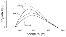
- NO 2 / NO X ratio map 71 is one in which NO 2 / NO X ratio corresponding to a spatial velocity SVa and DOC temperature Ta in DOC21 obtained by previously measured is mapped .
- the theoretical NO 2 / NO X ratio in the equilibrium state is shown by a two-dot chain line characteristic curve.
- the first reaction efficiency map 72 is a map in which the reaction efficiencies corresponding to the space velocity SVb and the DPF temperature Tb in the DPF 22 obtained by actual measurement in advance are mapped.
- the second reaction efficiency map 73 is a map in which the reaction efficiency according to the PM deposition amount in the DPF 22 obtained by actual measurement in advance is mapped.
- the PM deposition amount term map 74, the ⁇ term map 75, and the temperature term map 76 are mapped based on previously obtained actual measurement values and the like.
- the emission calculation unit 35A calculates the PM emission amount by correcting the value obtained from the engine speed Ne, the fuel injection amount Qf, and the PM emission amount map with the atmospheric pressure Pa or the like.
- the NO 2 oxidation amount calculation unit 35B performs a NO 2 supply amount calculation process and a reaction efficiency calculation process in calculating the NO 2 oxidation amount.
- NO 2 oxidation amount calculating section 35B is NO 2 in the supply amount calculation process, the NO X emissions from the engine 10, NO 2 / NO X ratio map 71 shown in the space velocity SVa and DOC temperature Ta and 7 in DOC21
- the NO 2 supply amount to the DPF 22 is calculated by multiplying the NO 2 / NO X ratio obtained from
- the NO 2 oxidation amount calculation unit 35B calculates the first reaction efficiency obtained from the space velocity SVb and the DPF temperature Tb in the DPF 22 and the first reaction efficiency map 72 shown in FIG.
- NO 2 oxidation amount calculation unit 35B determines the NO 2 consumption by multiplying the reaction efficiency obtained in NO 2 supply amount and reaction efficiency calculation process obtained by NO 2 supply amount calculation process, NO 2 consumption was determined
- the NO 2 oxidation amount is calculated by dividing the amount by the NO 2 / C mass ratio (converted into carbon C).
- Md PM deposition amount
- [O 2 ] O 2 concentration in exhaust gas
- Ea activation energy
- R gas constant
- Tb DPF temperature
- ⁇ and ⁇ reaction orders.
- k 0 ⁇ Md ⁇ is a PM accumulation amount term
- the O 2 oxidation amount calculation unit 35C uses the PM accumulation amount term map 74 shown in FIG. 10 to calculate this PM accumulation amount term.
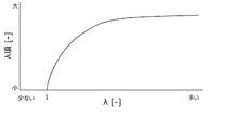
- [O 2 ] ⁇ in the above calculation formula is a ⁇ (air excess ratio) term
- the O 2 oxidation amount calculation unit 35C uses the ⁇ term map 75 shown in FIG. 11 for the calculation of this ⁇ term.
- exp (-Ea / RTb) is a temperature term
- the O 2 oxidation amount calculation unit 35C uses the temperature term map 76 shown in FIG. 12 to calculate this temperature term.
- the regeneration control unit 34 uses, as the regeneration mode of the DPF 22, the normal regeneration mode and the assist regeneration mode in which the DPF temperature Tb is equal to or lower than the above-described first target temperature because the post injection is not performed, and the fuel by the post injection. Due to the relatively large injection amount, the DPF temperature Tb is controlled to the above-described second target temperature, the reset regeneration mode, the stationary regeneration mode, the recovery second regeneration mode, and the fuel injection amount by the post injection becomes relatively small. Therefore, the DPF temperature Tb has the recovery first regeneration mode in which the DPF temperature Tb is controlled to the first target temperature.
- the NO 2 oxidation amount calculation unit 35B includes an optimization processing unit 35D that optimizes the NO 2 oxidation amount calculated by the NO 2 oxidation amount calculation unit 35B according to the regeneration mode switched by the regeneration mode switching unit 36. It is equipped.
- One of the regeneration mode is a reset regeneration mode in which the target temperature of the DPF 22 is set to the second target temperature, a stationary regeneration mode, or a recovery second regeneration mode.
- the high temperature injection regeneration mode the amount of unburned fuel supplied by post injection is relatively large, and along with this, the amount of NO 2 reduced by the HC contained in the unburned fuel is also large. Therefore, as shown in FIG. 13, the contribution of NO 2 to the PM deposited on the DPF 22 is negligibly lower than the contribution of O 2 to PM.
- the optimization processing unit 35D causes the NO 2 oxidation amount calculation unit 35B. to stops the calculation of the NO 2 oxidation amount with the NO 2 oxidation amount is output as the calculation result from NO 2 oxidation amount calculation unit 35B performs a first optimization process to 0 (zero).
- the regeneration mode is the recovery first regeneration mode in which the target temperature of the DPF 22 is set to the first target temperature lower than the second target temperature
- the unburned fuel supplied by the post injection becomes relatively small, Along with this, the amount of NO 2 reduced by the HC contained in the unburned fuel also decreases. Therefore, as shown in FIG. 13, the contribution of NO 2 to the PM deposited on the DPF 22 is higher than that of O 2 to the extent that it cannot be ignored.
- the PM deposition amount estimation unit 35 is performed.
- the PM deposition amount in the recovery first regeneration mode which is estimated by, becomes larger than the actual PM deposition amount by an amount corresponding to the oxidation contribution of NO 2 to PM.
- the actual PM deposition amount has decreased to the above-described predetermined threshold value (sixth threshold value t6 shown in FIG. 3D)
- the PM deposited on the DPF 22 is gently oxidized (burned) and removed.
- the recovery first reproduction mode to be continued will be unnecessarily long. As a result, the recovery first regeneration mode is performed unnecessarily long and the number of post-injections increases, resulting in deterioration of fuel efficiency and dilution of oil with fuel.
- the NO 2 oxidation amount calculation unit 35B is used in the recovery first regeneration mode as in the normal regeneration mode and the assist regeneration mode. It is necessary to accurately calculate the amount of dioxidation. However, when calculating the NO 2 oxidation amount in the recovery first reproduction mode and also serves as a NO 2 / NO X ratio map 71 used in the case of the normal reproduction mode and assisted reproduction mode, NO 2 due to the post injection in reducing recover first reproduction mode, NO NO 2 oxidation amount calculated by the second oxide amount calculating section 35B is larger than the actual NO 2 oxidation amount.
- the PM accumulation amount estimated by the PM accumulation amount estimating unit 35 in the recovery first regeneration mode becomes smaller than the actual PM accumulation amount, and thus the actual PM accumulation amount becomes the predetermined threshold value (FIG. 3).
- the reproduction mode switching unit 36 switches the reproduction mode from the recovery first reproduction mode to the recovery second reproduction mode, and the reproduction control unit 34 Raises the DPF temperature Tb to the above-mentioned second target temperature, there is a possibility that the PM excessively accumulated in the DPF 22 will be rapidly oxidized (combusted) and the DPF 22 will excessively rise in temperature.
- optimizing section 35D when the reproduction mode is switched to the recovery first reproduction mode by the reproduction mode switching unit 36, the NO 2 oxidation amount calculated by the NO 2 oxidation amount calculating section 35B, DPF temperature
- a second optimization process is performed to optimize Tb according to the fuel injection amount in the post injection for controlling the first target temperature.
- the PM accumulation amount estimation unit 35 a NO 2 / NO X ratio map 71, first 1NO 2 / NO X ratio serving as a for normal reproduction mode and the for assisted reproduction mode
- a map 71A and a second NO 2 / NO X ratio map 71B dedicated to the recovery first regeneration mode are provided.
- the 1NO 2 / NO X ratio map 71A is to reduce the NO 2 by the post injection is mapped to NO 2 / NO X ratio not considered.
- the second NO 2 / NO X ratio map 71B is a map of the NO 2 / NO X ratio in which the reduction of NO 2 due to the post injection in the recovery first regeneration mode is taken into consideration.
- the optimization processing unit 35D based on the recovery first regeneration flag output when the regeneration mode switching unit 36 switches the regeneration mode to the recovery first regeneration mode, the NO 2 oxidation amount calculation unit. 35B switches the NO 2 / NO X ratio map 71 used in the NO 2 supply amount calculation process shown in FIG. 5 from the first NO 2 / NO X ratio map 71A to the second NO 2 / NO X ratio map 71B.
- the NO 2 oxidation amount calculation unit 35B causes the NO caused by post injection in the recovery first regeneration mode. It is possible to calculate the NO 2 oxidation amount with high accuracy in consideration of the decrease of 2 , so that the PM deposition amount estimation unit 35 can accurately estimate the PM deposition amount in the recovery first regeneration mode. As a result, in the recovery first regeneration mode, the PM accumulation amount estimated by the PM accumulation amount estimating unit 35 becomes larger than the actual PM accumulation amount, which results in deterioration of fuel consumption and dilution of oil with fuel. It is possible to avoid the possibility that the DPF 22 is overheated due to the PM accumulation amount estimated by the PM accumulation amount estimating unit 35 being smaller than the actual PM accumulation amount. be able to.
- the NO 2 oxidation amount calculation unit 35B is the same as in the injection regeneration mode (recovery first regeneration mode) also in the high temperature injection regeneration mode in the reset regeneration mode, the stationary regeneration mode, and the recovery second regeneration mode.
- the NO 2 oxidation amount may be calculated using the second NO 2 / NO X ratio map 71B.
- the accumulation amount estimation unit 35 includes a third map for the high temperature injection regeneration mode, and the regeneration mode switching unit 36 sets the regeneration mode to the high temperature injection regeneration mode, that is, the reset regeneration mode, the stationary regeneration mode, and the recovery second regeneration mode. Even if the NO 2 oxidation amount calculation unit 35B is configured to switch the map used for the calculation of the NO 2 oxidation amount to the third map when the NO 2 oxidation amount is calculated, the NO 2 oxidation amount calculation unit 35B may be configured to calculate the NO 2 oxidation amount. Good.
- the regeneration mode switching unit 36 switches the regeneration mode to be executed to the reset regeneration mode and the PM accumulation amount of the DPF 22 is equal to or more than the predetermined amount
- the regeneration mode to be executed is changed from the reset regeneration mode to the stationary regeneration.
- the PM accumulation amount of the DPF 22 is equal to or more than the predetermined amount even after the mode is switched to the regenerative mode to be executed and the stationary regenerating mode is switched to, the regenerating mode to be executed is switched from the stationary regenerating mode to the recovery regenerating mode. May be.
- the thresholds t1 to t7 for switching the reproduction modes executed by the reproduction mode switching unit 36 and the types of the reproduction modes switched by the reproduction mode switching unit 36 can be variously changed.
- the exhaust gas purification system according to the present invention can be applied to work vehicles such as tractors and wheel loaders equipped with an engine.
Landscapes
- Engineering & Computer Science (AREA)
- Chemical & Material Sciences (AREA)
- Combustion & Propulsion (AREA)
- General Engineering & Computer Science (AREA)
- Mechanical Engineering (AREA)
- Chemical Kinetics & Catalysis (AREA)
- Health & Medical Sciences (AREA)
- Biomedical Technology (AREA)
- Toxicology (AREA)
- Environmental & Geological Engineering (AREA)
- Analytical Chemistry (AREA)
- General Chemical & Material Sciences (AREA)
- Oil, Petroleum & Natural Gas (AREA)
- Processes For Solid Components From Exhaust (AREA)
- Exhaust Gas After Treatment (AREA)
- Electrical Control Of Air Or Fuel Supplied To Internal-Combustion Engine (AREA)
- Combined Controls Of Internal Combustion Engines (AREA)
- Filtering Of Dispersed Particles In Gases (AREA)
- Exhaust Gas Treatment By Means Of Catalyst (AREA)
Abstract
PM捕集用のフィルタにおけるPM堆積量を精度良く推定する。排気浄化システムは、PM捕集フィルタ用の再生モードとして、ポスト噴射を行わない非噴射再生モードと、ポスト噴射にてフィルタ温度を所定の目標温度に制御する噴射再生モードとを有し、排出量計算部(35A)が計算するエンジン(10)からのPM排出量と、NO2酸化量計算部(35B)が計算するPMのNO2酸化量と、O2酸化量計算部(35C)が計算するPMのO2酸化量とから、フィルタ(22)でのPM堆積量を推定する堆積量推定部(35)と、PM堆積量に基づいて再生モードを切り替える再生モード切替部(36)とを有し、NO2酸化量計算部(35B)は、再生モード切替部(36)が再生モードを非噴射再生モードから噴射再生モードに切り替えた場合に、NO2酸化量の計算に使用するマップを、非噴射再生モード用の第1マップから噴射再生モード用の第2マップに切り替える。
Description
本発明は、エンジンが搭載されたトラクタやホイールローダなどの作業車両などに備えられる排気浄化システムに関する。
従来、エンジンからの排気を浄化するものとしては、例えば、排気に含まれたPM(粒子状物質)を捕集する排気ガス浄化装置(DPF)と、排気ガス浄化装置を再生する制御手段とを備え、排気ガス浄化装置には、酸化作用によって排気に含まれたNOX(窒素酸化物)におけるNO2(二酸化窒素)の割合を多くする酸化触媒が内蔵されたエンジンがある(例えば特許文献1参照)。
又、例えば、酸化作用によって排気に含まれたNOX(窒素酸化物)におけるNO2(二酸化窒素)の割合を多くする酸化触媒と、排気に含まれたPMを捕集するフィルタとを有する排気ガス浄化装置と、排気ガス浄化装置に堆積したPMを焼却する再生制御を行う制御部とを備えた排気ガス浄化システムがある(例えば特許文献2参照)。
又、例えば、酸化作用によって排気に含まれたNOX(窒素酸化物)におけるNO2(二酸化窒素)の割合を多くする酸化触媒と、排気に含まれたPMを捕集するフィルタとを有する排気ガス浄化装置と、排気ガス浄化装置に堆積したPMを焼却する再生制御を行う制御部とを備えた排気ガス浄化システムがある(例えば特許文献2参照)。
特許文献1に記載のエンジンにおいて、制御手段は、排気ガス浄化装置の再生モードとして、ポスト噴射を行って排気ガス浄化装置における排気温度を高くすることで、排気ガス浄化装置に堆積したPMの燃焼除去を促進させるリセット再生(第一再生)と、ポスト噴射を行わずに排気ガス浄化装置に堆積したPMを燃焼除去するアシスト再生(第二再生)とを有している。又、制御手段は、排気ガス浄化装置に堆積したPM堆積量の推定方式として、排気ガス浄化装置の前後差圧に基づいてPM堆積量を推定する差圧式推定と、エンジンの運転状態に基づいてPM堆積量を推定する計算式推定とを有している。そして、制御手段は、リセット再生及びアシスト再生を行っていない場合は差圧式推定によってPM堆積量を推定し、リセット再生又はアシスト再生を行っている場合は計算式推定によってPM堆積量を推定するように構成されている。
特許文献2に記載の排気ガス浄化システムにおいて、制御部が行う再生制御(再生モード)には、ポスト噴射を行わないことで排気ガス浄化装置内の温度を比較的低温(300~400度程度)にするアシスト再生制御、及び、ポスト噴射を行うことで排気ガス浄化装置内の温度を比較的高温(500~700度程度)にするリセット再生制御とステーショナリ再生制御とリカバリ再生制御とが含まれている。そして、制御部は、アシスト再生制御を行ってもフィルタに堆積したPM堆積量が所定量以上残っている場合にリセット再生制御を行い、リセット再生制御を行ってもPM堆積量が所定量以上残っている場合にステーショナリ再生制御を行い、ステーショナリ再生制御を行ってもPM堆積量が所定量以上残っている場合にリカバリ再生制御を行う。又、リカバリ再生制御には、ポスト噴射における燃料噴射量を抑えることでステーショナリ再生制御よりも排気ガス浄化装置内の温度を低温にした状態で行われるリカバリ第1再生制御と、リカバリ第1再生制御よりも排気ガス浄化装置内の温度を高温にした状態で行われるリカバリ第2再生制御とが含まれている。そして、制御部は、リカバリ再生制御においては、低温のリカバリ第1再生制御を行った後に高温のリカバリ第2再生制御を行うことで、フィルタにおいてPMが過堆積になっている状態で高温のリカバリ再生制御が行われることで生じる虞のあるフィルタの過昇温を回避するようにしている。
特許文献1に記載のエンジンにおいては、リセット再生又はアシスト再生を行っている場合に計算式推定によってPM堆積量を推定することが記載されている。しかしながら、リセット再生はポスト噴射を行うものであるのに対し、アシスト再生はポスト噴射を行わないものであることから、例えば、アシスト再生においてPM堆積量を推定する場合に用いる計算式、つまり、酸化触媒の酸化作用によって多くなるNO2が考慮された計算式を、リセット再生においてPM堆積量を推定する場合に用いると、リセット再生においてPM堆積量を推定する場合の推定精度が低下することになる。
これは、ポスト噴射が行われると、酸化触媒の酸化作用によって多くなるNO2が、ポスト噴射で供給される未燃燃料に含まれているHC(炭化水素)によってNO(一酸化窒素)やN2(窒素)などに還元されて減少することに起因している。そのため、ポスト噴射による燃料噴射量を多くして排気温度を高くするほど、還元されるNO2が多くなってNO2によるPM酸化量が少なくなり、排気ガス浄化装置における実際のPM堆積量が計算式推定によるPM堆積量よりも多くなる。
一方、特許文献2に記載の排気ガス浄化システムにおいては、ポスト噴射を行う再生制御として、リセット再生制御とステーショナリ再生制御とリカバリ再生制御とがある。ステーショナリ再生制御は、リセット再生制御を行ってもフィルタに堆積したPM堆積量が所定量以上残っている場合に行われる。リカバリ再生制御は、ステーショナリ再生制御を行ってもフィルタに堆積したPM堆積量が所定量以上残っている場合に行われる。リカバリ再生制御においては、先に低温のリカバリ第1再生制御を行った後に高温のリカバリ第2再生制御を行うように構成されている。このように構成された排気ガス浄化システムにおいて、前述したようなポスト噴射に起因したPM堆積量の推定精度の低下が生じると、リセット再生制御からステーショナリ再生制御に切り替わるときに、既にフィルタにおいてPMが過堆積になっている虞や、低温のリカバリ第1再生制御から高温のリカバリ第2再生制御に切り替わるときに、フィルタでのPMの過堆積が改善されていない虞がある。このような過堆積状態において、排気ガス浄化装置内の温度を600~700度程度の高温にするステーショナリ再生制御又はリカバリ第2再生制御が行われると、フィルタに過堆積したPMが、ステーショナリ再生制御又はリカバリ第2再生制御の開始時に急激に酸化(燃焼)されてフィルタが過昇温する虞がある。
この実情に鑑み、本発明の主たる課題は、ポスト噴射が行われない非噴射再生モードとポスト噴射が行われる噴射再生モードとのそれぞれにおいて精度の高いPM堆積量の推定を行えるようにする点にある。
本発明の第1特徴構成は、排気浄化システムにおいて、
エンジンからの排気に含まれた未燃焼ガスを酸化させる酸化触媒と、前記排気に含まれた粒子状物質を捕集するフィルタと、前記フィルタに堆積した前記粒子状物質を酸化除去して前記フィルタを再生させる再生制御部とを備え、
前記再生制御部は、前記フィルタの再生モードとして、ポスト噴射を行わない非噴射再生モードと、前記ポスト噴射を行って前記フィルタの温度を所定の目標温度に制御する噴射再生モードとを有し、
前記再生制御部には、前記エンジンの運転状態に基づいて前記フィルタにおける前記粒子状物質の堆積量を推定する堆積量推定部と、前記堆積量に基づいて実行する再生モードを切り替える再生モード切替部とが含まれており、
前記堆積量推定部は、前記エンジンからの前記粒子状物質の排出量を計算する排出量計算部と、二酸化窒素による前記粒子状物質の酸化量であるNO2酸化量を計算するNO2酸化量計算部と、酸素による前記粒子状物質の酸化量であるO2酸化量を計算するO2酸化量計算部とを有して、これらの各計算部からの計算結果に基づいて前記粒子状物質の堆積量を推定し、
前記NO2酸化量計算部は、窒素酸化物に含まれる二酸化窒素の比率を示すマップを用いて前記NO2酸化量を計算し、
前記堆積量推定部には、前記マップとして、非噴射再生モード用の第1マップと噴射再生モード用の第2マップとが備えられ、
前記NO2酸化量計算部は、前記再生モード切替部が前記再生モードを前記非噴射再生モードから前記噴射再生モードに切り替えた場合に、前記マップを前記第1マップから前記第2マップに切り替える点にある。
エンジンからの排気に含まれた未燃焼ガスを酸化させる酸化触媒と、前記排気に含まれた粒子状物質を捕集するフィルタと、前記フィルタに堆積した前記粒子状物質を酸化除去して前記フィルタを再生させる再生制御部とを備え、
前記再生制御部は、前記フィルタの再生モードとして、ポスト噴射を行わない非噴射再生モードと、前記ポスト噴射を行って前記フィルタの温度を所定の目標温度に制御する噴射再生モードとを有し、
前記再生制御部には、前記エンジンの運転状態に基づいて前記フィルタにおける前記粒子状物質の堆積量を推定する堆積量推定部と、前記堆積量に基づいて実行する再生モードを切り替える再生モード切替部とが含まれており、
前記堆積量推定部は、前記エンジンからの前記粒子状物質の排出量を計算する排出量計算部と、二酸化窒素による前記粒子状物質の酸化量であるNO2酸化量を計算するNO2酸化量計算部と、酸素による前記粒子状物質の酸化量であるO2酸化量を計算するO2酸化量計算部とを有して、これらの各計算部からの計算結果に基づいて前記粒子状物質の堆積量を推定し、
前記NO2酸化量計算部は、窒素酸化物に含まれる二酸化窒素の比率を示すマップを用いて前記NO2酸化量を計算し、
前記堆積量推定部には、前記マップとして、非噴射再生モード用の第1マップと噴射再生モード用の第2マップとが備えられ、
前記NO2酸化量計算部は、前記再生モード切替部が前記再生モードを前記非噴射再生モードから前記噴射再生モードに切り替えた場合に、前記マップを前記第1マップから前記第2マップに切り替える点にある。
本構成によれば、非噴射再生モードにおいては、ポスト噴射に伴う炭化水素の還元作用によって減少する二酸化窒素を考慮する必要がないことから、NO2酸化量計算部は、非噴射再生モード用の第1マップ、つまり、ポスト噴射に伴う二酸化窒素の減少が考慮されていない第1マップを用いて、二酸化窒素の減少に伴う酸化量の低下を含まないNO2酸化量を計算する。これにより、堆積量推定部は、排出量計算部が計算したエンジンからの粒子状物質の排出量と、NO2酸化量計算部が計算したポスト噴射による酸化量の低下を含まないNO2酸化量と、O2酸化量計算部が計算したO2酸化量とに基づいて、フィルタにおける粒子状物質の堆積量を精度良く推定することができる。
又、噴射再生モードにおいては、ポスト噴射に伴う炭化水素の還元作用によって減少する二酸化窒素を考慮する必要があることから、NO2酸化量計算部は、噴射再生モード用の第2マップ、つまり、ポスト噴射に伴う二酸化窒素の減少が考慮された第2マップを用いて、二酸化窒素の減少に伴う酸化量の低下を含むNO2酸化量を計算する。これにより、堆積量推定部は、排出量計算部が計算したエンジンからの粒子状物質の排出量と、NO2酸化量計算部が計算したポスト噴射による酸化量の低下を含むNO2酸化量と、O2酸化量計算部が計算したO2酸化量とに基づいて、フィルタにおける粒子状物質の堆積量を精度良く推定することができる。
つまり、堆積量推定部は、非噴射再生モードと噴射再生モードとのいずれにおいてもフィルタにおける粒子状物質の堆積量を精度良く推定することができる。
本発明の第2特徴構成は、
前記再生制御部は、前記再生モードとして、前記ポスト噴射を行って前記フィルタの温度を前記所定の目標温度よりも高い目標温度に制御する高温噴射再生モードを有し、
前記NO2酸化量計算部は、前記再生モード切替部が前記再生モードを前記高温噴射再生モードに切り替えた場合に前記NO2酸化量を零にする点にある。
前記再生制御部は、前記再生モードとして、前記ポスト噴射を行って前記フィルタの温度を前記所定の目標温度よりも高い目標温度に制御する高温噴射再生モードを有し、
前記NO2酸化量計算部は、前記再生モード切替部が前記再生モードを前記高温噴射再生モードに切り替えた場合に前記NO2酸化量を零にする点にある。
高温噴射再生モードにおいては、フィルタの温度を所定の目標温度よりも高い目標温度に制御するために、ポスト噴射で供給される未燃燃料が多くなり、これに伴って、未燃燃料に含まれている炭化水素による二酸化窒素の還元が促進される。そのため、高温噴射再生モードにおいては、フィルタに堆積した粒子状物質に対する酸素の酸化寄与度に比べて二酸化窒素の酸化寄与度が無視できる程度に低くなる。そこで、本構成においては、再生モード切替部が再生モードを高温噴射再生モードに切り替えた場合は、NO2酸化量計算部がNO2酸化量を零にするようにしている。
つまり、高温噴射再生モードにおいては、NO2酸化量計算部がNO2酸化量を高い精度で計算する必要がなくなる。
その結果、高温噴射再生モードにおいてNO2酸化量計算部がNO2酸化量を計算するときの負荷の軽減を図りながら、堆積量推定部がフィルタにおける粒子状物質の堆積量を推定するときの推定精度を高めることができる。
以下、本発明を実施するための形態の一例を図面に基づいて説明する。
尚、本実施形態にて例示する排気浄化システムは、エンジンが搭載されたトラクタやホイールローダなどの作業車両などに備えることができる。
尚、本実施形態にて例示する排気浄化システムは、エンジンが搭載されたトラクタやホイールローダなどの作業車両などに備えることができる。
図1に示すように、本実施形態に例示された排気浄化システム1は、エンジン10からの排気を浄化する排気浄化装置20、エンジン10に関する制御を実行するエンジンECU(エンジン電子制御ユニット)30、エンジン10からの排気の一部をエンジン10の吸気側に還元するEGRシステム(排気再循環システム)40、及び、エンジン10が吸い込む空気の圧力(密度)を高くする過給機50、などを有している。エンジンECU30には、CPUや不揮発性メモリなどを有するマイクロコントローラなどが搭載されている。
図1に示すように、エンジン10には、燃料噴射量や噴射タイミングなどの電子制御を可能にするコモンレールシステム60を有する4気筒のディーゼルエンジンが採用されている。エンジン10の気筒数は、エンジン10が搭載される作業車の種類や必要トルクなどに応じて種々の変更が可能である。エンジン10は、吸気経路2に導入された空気を各燃焼室11に分配する吸気マニホールド12、及び、各燃焼室11からの排気を排気経路3に集める排気マニホールド13、などを有している。エンジン10には、クランク軸14の回転数をエンジン回転数として検出する電磁ピックアップ式の回転センサ15、吸気マニホールド12の内圧を吸気圧として検出する吸気圧センサ16、及び、排気マニホールド13の内圧を排気圧として検出する排気圧センサ17、などが備えられている。
図1に示すように、吸気経路2には、吸気経路2に導入される空気量を調節する吸気バルブ4が備えられている。吸気バルブ4は、エンジンECU30に備えられた吸気制御部31によって開度が制御される。吸気制御部31は、吸気バルブ4の開度を制御することで空気過剰率λを調節する。排気経路3には、排気中のO2(酸素)濃度を検出する酸素センサ5が備えられている。
図1に示すように、排気浄化装置20には、エンジン10からの排気に含まれた未燃焼ガスを酸化させる酸化触媒としてのDOC(ディーゼル酸化触媒)21と、エンジン10からの排気に含まれたPM(粒子状物質)を捕集するフィルタとしてのDPF(ディーゼル・パティキュレート・フィルタ)22とを有するDPFユニットが採用されている。未燃焼ガスには、HC(炭化水素)、CO(一酸化炭素)、NOX(窒素酸化物)、などが含まれている。排気浄化装置20においては、DOC21の酸化作用により、HCがH2O(水)とCO2(二酸化炭素)とに酸化され、COがCO2(二酸化炭素)に酸化され、NOXのうちのNO(一酸化窒素)がNO2(二酸化窒素)に酸化される。そして、DPF22に捕集されて堆積したPM(粒子状物質)が、DOC21を通過した排気に含まれているO2とNO2によって酸化(燃焼)されて除去される。これにより、DPF22を再生させることができる。排気浄化装置20には、排気浄化装置20におけるDOC21の排気方向上流側の温度をDOC温度Taとして検出するDOC温度センサ23、排気浄化装置20におけるDPF22の排気方向上流側の温度をDPF温度Tbとして検出するDPF温度センサ24、及び、排気浄化装置20におけるDPF22の排気方向上流側と排気方向下流側との差圧を検出する差圧センサ25、などが備えられている。
図1に示すように、EGRシステム40は、吸気経路2と排気経路3とを接続するEGR経路41、EGR経路41を通る排気を冷却するEGRクーラ42、及び、EGR経路41に備えられたEGRバルブ43、などを有している。EGRバルブ43は、エンジンECU30に備えられたEGR制御部32によって開度が制御される。EGR制御部32は、吸気圧センサ16が検出する吸気圧と排気圧センサ17が検出する排気圧との差圧などに基づいてEGRバルブ43の開度を制御することで、吸気経路2の空気に混入される排気量を調節する。EGRシステム40は、適量の排気を吸気経路2の空気に混入させた混合気を各燃焼室11に導入させることで、排気に含まれるNOXの低減や燃費性能の向上を図れるようにする。
図1に示すように、過給機50は、排気経路3に備えられたタービン51、吸気経路2に備えられたコンプレッサ52、及び、タービン51とコンプレッサ52とを一体回転させる連結軸53、などを有している。過給機50は、排気経路3を通る排気によってタービン51が回転し、この回転に伴ってコンプレッサ52が回転することで、吸気経路2の空気を圧縮してエンジン10の各燃焼室11に送り込む。
図1に示すように、コモンレールシステム60は、燃料を圧送するサプライポンプ61、圧送された燃料を蓄圧するコモンレール62、及び、蓄圧した燃料を各燃焼室11に噴射する4つのインジェクタ63、などを有している。各インジェクタ63による燃料の噴射量や噴射タイミングなどは、エンジンECU30に備えられた噴射制御部33によって制御される。
噴射制御部33は、パイロット噴射とプレ噴射とメイン噴射とアフタ噴射とポスト噴射とが適正に行われるように各インジェクタ63などの作動を制御する。噴射制御部33は、メイン噴射の前にパイロット噴射を行うことで、予混合燃焼によるPMや燃焼騒音の低減を図れるようにする。噴射制御部33は、メイン噴射の前にプレ噴射を行うことで、メイン噴射での急激な燃焼を抑制してNOXや燃焼騒音の低減を図れるようにする。噴射制御部33は、メイン噴射の後にアフタ噴射を行うことで、拡散燃焼を活発化させてメイン噴射で発生したPMの低減を図れるようにする。噴射制御部33は、アフタ噴射の後にDPF再生用のポスト噴射を行うことで、排気の昇温や還元成分の供給によって触媒を活性化させて、排気に含まれたO2やNO2によるPMの酸化を促進させる。
図1に示すように、エンジンECU30には、DPF22に堆積したPMを酸化除去してDPF22を再生させる再生制御部34が備えられている。図2~3に示すように、再生制御部34は、DPF22の再生モードとして、ポスト噴射を行わない非噴射再生モードとして通常再生モードとアシスト再生モードとを有し、ポスト噴射を行う再生モードとしてリセット再生モードとステーショナリ再生モードとリカバリ再生モードとを有している。リカバリ再生モードには、リカバリ再生モードの開始時に実行されるリカバリ第1再生モードと、リカバリ第1再生モードが実行されることでDPF22におけるPM堆積量が所定の閾値まで低下したときに実行されるリカバリ第2再生モードとが含まれている。ポスト噴射を行う再生モードのうち、リカバリ第1再生モードは、ポスト噴射による燃料噴射量を少なくして、DPF温度Tbを所定の目標温度(例えば500度、以下、第1目標温度と称する)に制御する噴射再生モードである。リセット再生モードとステーショナリ再生モードとリカバリ第2再生モードは、ポスト噴射による燃料噴射量を多くして、DPF温度Tbを第1目標温度よりも高い第2目標温度(例えば600度)に制御する高温噴射再生モードである。
図2に示すように、再生制御部34は、通常再生モードにおいては、DPF22の目標温度を設定せずに、作業負荷などに応じてエンジン回転数などが変更されるエンジン10の通常運転時に得られる排気温度を利用する。これにより、DPF温度Tbは、エンジン10の通常運転時に変動する排気温度に応じた成行きで約200~500度の間で変動する。すると、排気に含まれた未燃焼ガスのHCとCOとNOXとが、DOC21の酸化作用によってCO2やNO2などに酸化されて、NOXにおけるNO2の割合が多くなる。これにより、DPF22に堆積したPMが、DOC21を通過した排気に含まれているNO2とO2によって酸化(燃焼)されて除去される。
図2に示すように、再生制御部34は、アシスト再生モードにおいては、DPF22の目標温度を設定せずに、作業負荷などに応じてエンジン回転数などが変更されるエンジン10の通常運転時に得られる排気温度を利用するのに加えて、吸気バルブ4を所定開度まで閉弁して空気過剰率λを小さくするとともにアフタ噴射を行わせる。これにより、エンジン10の通常運転時に得られる排気温度が約300~500度程度に上昇し、DPF温度Tbは、エンジン10の通常運転時に変動する排気温度に応じた成行きで約300~500度の間で変動する。すると、DOC21が活性化されて、DOC21の酸化作用によるNO2の生成が促進されることで、NOXにおけるNO2の割合が更に多くなる。これにより、DPF22に堆積したPMが、DOC21を通過した排気に含まれているNO2とO2により、PMに対するNO2の酸化寄与度がO2の酸化寄与度よりも高い状態で効率的に酸化(燃焼)されて除去される。
図2に示すように、再生制御部34は、リセット再生モードにおいては、DPF22の目標温度を前述した第2目標温度に設定する。そして、この第2目標温度を得るために、吸気バルブ4を所定開度まで閉弁して空気過剰率λを小さくするとともにアフタ噴射に加えてポスト噴射を行わせる。これにより、このときの反応熱を利用して排気温度とともにDPF温度Tbを第2目標温度に制御する。このとき、DOC21の酸化作用で生成されるNO2の多くが、ポスト噴射で供給された未燃燃料に含まれているHCによってNOやN2(窒素)などに還元される。その結果、DPF22に堆積したPMが、DOC21を通過した排気に含まれているO2によって急速に酸化(燃焼)されて除去される。
図2に示すように、再生制御部34は、ステーショナリ再生モードにおいては、作業車両による作業が停止されてエンジン回転数が所定の高回転数に維持(固定)された条件下で、DPF22の目標温度を前述した第2目標温度に設定する。そして、この第2目標温度を得るために、吸気バルブ4を所定開度まで閉弁して空気過剰率λを小さくするとともにアフタ噴射とポスト噴射とを行わせる。これにより、このときの反応熱を利用して排気温度とともにDPF温度Tbを第2目標温度に制御する。このとき、DOC21の酸化作用で生成されるNO2の多くが、ポスト噴射で供給された未燃燃料に含まれているHCによってNOやN2などに還元される。その結果、DPF22に堆積したPMが、エンジン回転数が所定の高回転数に維持されてDPF温度Tbが第2目標温度に精度良く制御された条件下で、DOC21を通過した排気に含まれているO2によって効率良く急速に酸化(燃焼)されて除去される。
図2に示すように、再生制御部34は、リカバリ第1再生モードにおいては、作業車両による作業が停止されてエンジン回転数が所定の高回転数に維持(固定)された条件下で、DPF22の目標温度を前述した第1目標温度に設定する。そして、この第1目標温度を得るために、吸気バルブ4を所定開度まで閉弁して空気過剰率λを小さくするとともにアフタ噴射とポスト噴射とを行わせるのに加えて、ポスト噴射における燃料噴射量を、リセット再生モードやステーショナリ再生モードのときよりも少なくする。これにより、排気温度とともにDPF温度Tbを、リセット再生モードやステーショナリ再生モードのときよりも低い第1目標温度に制御する。このようにDPF温度Tbを比較的低くすることで、DPF22に堆積したPMが、エンジン回転数が所定の高回転数に維持されてDPF温度Tbが第1目標温度に精度良く制御された条件下で、DOC21を通過した排気に含まれているNO2とO2によって緩やかに酸化(燃焼)されて除去される。
図2に示すように、再生制御部34は、リカバリ第2再生モードにおいては、作業車両による作業が停止されてエンジン回転数が所定の高回転数に維持(固定)された条件下で、DPF22の目標温度を前述した第2目標温度に設定する。そして、この第2目標温度を得るために、吸気バルブ4を所定開度まで閉弁して空気過剰率λを小さくするとともにアフタ噴射とポスト噴射とを行わせるのに加えて、ポスト噴射における燃料噴射量を、リセット再生モードやステーショナリ再生モードのときと同じにする。これにより、排気温度とともにDPF温度Tbを、リセット再生モードやステーショナリ再生モードのときと同じ第2目標温度に制御する。このようにDPF温度Tbを比較的高くすることで、DPF22に堆積したPMが、エンジン回転数が所定の高回転数に維持されてDPF温度Tbが第2目標温度に精度良く制御された条件下で、DOC21を通過した排気に含まれているO2によって効率的に急速に酸化(燃焼)されて除去される。
このように、リカバリ再生モードにおいては、再生制御部34が、DPF22に堆積したPMを緩やかに酸化除去するリカバリ第1再生モードを行った後に、DPF22に堆積したPMを効率的に急速に酸化除去するリカバリ第2再生モードを行うことで、DPF22に過堆積したPMがリカバリ再生モードの開始時に急激に酸化(燃焼)されてDPF22が過昇温する虞を回避しながら、DPF22に堆積したPMを効率良く酸化除去することができる。
図1に示すように、再生制御部34には、エンジン10の運転状態に基づいてDPF22におけるPM堆積量を推定するPM堆積量推定部35と、PM堆積量推定部35が推定したPM堆積量などに基づいて実行する再生モードを切り替える再生モード切替部36とが含まれている。
図4に示すように、PM堆積量推定部35は、エンジン10からのPM排出量を計算する排出量計算部35Aと、NO2によるPMの酸化量であるNO2酸化量を計算するNO2酸化量計算部35Bと、O2によるPMの酸化量であるO2酸化量を計算するO2酸化量計算部35Cとを有している。PM堆積量推定部35は、排出量計算部35Aが計算したPM排出量から、NO2酸化量計算部35Bが計算したNO2酸化量とO2酸化量計算部35Cが計算したO2酸化量とを加算したPM酸化量を減算することで、DPF22に供給されるPM供給量を計算し、計算したPM供給量を時間で積算した後、DPF22の容積で除算することでPM堆積量を推定する。
図3の(a)に示すように、再生モード切替部36は、通常再生モードにおいて、PM堆積量推定部35により推定されたPM堆積量が第1閾値t1まで上昇したときに、実行する再生モードを通常再生モードからアシスト再生モードに切り替える。
図3の(a)に示すように、再生モード切替部36は、アシスト再生モードにおいて、PM堆積量推定部35により推定されたPM堆積量が第2閾値t2まで低下したときに、実行する再生モードをアシスト再生モードから通常再生モードに切り替える。
図3の(b)に示すように、再生モード切替部36は、アシスト再生モードにおいて、PM堆積量推定部35により推定されたPM堆積量が第3閾値t3まで上昇したときに、実行する再生モードをアシスト再生モードからリセット再生モードに切り替える。
再生モード切替部36は、リセット再生モードにおいて、リセット再生禁止スイッチ6がユーザによって操作されたときに、実行する再生モードをリセット再生モードから通常再生モードに切り替える。このときの通常再生モードにおいては、図3の(c)に示すように、PM堆積量推定部35により推定されるPM堆積量が上昇する。
図3の(c)に示すように、再生モード切替部36は、リセット再生モードへの切り替えが禁止された通常再生モードにおいて、PM堆積量推定部35により推定されたPM堆積量が第4閾値t4まで上昇したときに、再生モードのステーショナリ再生モードへの切り替えを要求する。そして、この要求に応じて、ユーザにより作業車両による作業が停止されて作業車両の再生スイッチ7が操作されたときに、実行する再生モードを通常再生モードからステーショナリ再生モードに切り替える。又、この要求が無視された場合は、図3の(d)に示すように、通常再生モードが継続されて、PM堆積量推定部35により推定されるPM堆積量が上昇する。
図3の(d)に示すように、再生モード切替部36は、ステーショナリ再生モードへの切り替え要求が無視された通常再生モードにおいて、PM堆積量推定部35により推定されたPM堆積量が第5閾値t5まで上昇したときに、再生モードのリカバリ再生モードへの切り替えを要求する。そして、この要求に応じて、ユーザにより作業車両による作業が停止されて再生スイッチ7が操作されたときに、実行する再生モードを通常再生モードからリカバリ再生モードに切り替える。又、この要求が無視された場合は、図3の(e)に示すように、通常再生モードが継続されて、PM堆積量推定部35により推定されるPM堆積量が上昇する。
図3の(d)に示すように、再生モード切替部36は、リカバリ再生モードにおいては、先ず、DPF22が過昇温する虞を回避するためにリカバリ第1再生モードを実行し、リカバリ第1再生モードにおいてPM堆積量推定部35により推定されたPM堆積量が前述した所定の閾値である第6閾値t6まで低下したときに、実行する再生モードをリカバリ第1再生モードからリカバリ第2再生モードに切り替える。
図3の(e)に示すように、再生モード切替部36は、リカバリ再生モードへの切り替え要求が無視された通常再生モードにおいて、PM堆積量推定部35により推定されたPM堆積量が第7閾値t7まで上昇したときは、再生モードのリカバリ再生モードへの切り替えを禁止する。
図示は省略するが、リセット再生禁止スイッチ6及び再生スイッチ7は、排気浄化システム1が備えられた作業車両の運転部に配置されている。再生モード切替部36は、再生モードのステーショナリ再生モード又はリカバリ再生モードへの切り替え要求時には、例えば、点灯可能に構成された再生スイッチ7を点灯又は点滅させる、あるいは、作業車両の運転部に備えられた報知ブザーを作動させる、などの報知作動を行う。これにより、作業車両の運転部に搭乗したユーザに、再生モードのステーショナリ再生モード又はリカバリ再生モードへの切り替えを要求する。
PM堆積量推定部35によるPM堆積量の推定について詳述すると、図4に示すように、PM堆積量推定部35には、基本情報として、エンジン回転数Ne、燃料噴射量Qf、大気圧Pa、などが入力されている。PM堆積量推定部35には、その他の情報として、DOC温度Ta、DPF温度Tb、吸気質量流量Mi、排気質量流量Mo、排気体積流量Qo、空気過剰率λ、などが入力されている。PM堆積量推定部35は、排気体積流量QoをDOC21の容積で除算することでDOC21における空間速度SVaを計算し、排気体積流量QoをDPF22の容積で除算することで、DPF22における空間速度SVbを計算する。
図5~12に示すように、PM堆積量推定部35には、PM堆積量の推定に使用される各種のマップが備えられている。各種のマップには、PM排出量マップ、NO2/NOX比マップ71、第1反応効率マップ72、第2反応効率マップ73、PM堆積量項マップ74、λ項マップ75、温度項マップ76、などが含まれている。
PM排出量マップは、予め実測して得られたエンジン回転数Neと燃料噴射量Qfとに応じたエンジン10からのPM排出量がマッピングされたものである。
図7に示すように、NO2/NOX比マップ71は、予め実測して得られたDOC21における空間速度SVaとDOC温度Taとに応じたNO2/NOX比がマッピングされたものである。図7のNO2/NOX比マップ71においては、理論上の平衡状態でのNO2/NOX比が二点鎖線の特性曲線にて示されている。
図8に示すように、第1反応効率マップ72は、予め実測して得られたDPF22における空間速度SVbとDPF温度Tbとに応じた反応効率がマッピングされたものである。
図9に示すように、第2反応効率マップ73は、予め実測して得られたDPF22におけるPM堆積量に応じた反応効率がマッピングされたものである。
図10~12に示すように、PM堆積量項マップ74、λ項マップ75、温度項マップ76は、予め得られた実測値などに基づいてマッピングされたものである。
PM排出量マップは、予め実測して得られたエンジン回転数Neと燃料噴射量Qfとに応じたエンジン10からのPM排出量がマッピングされたものである。
図7に示すように、NO2/NOX比マップ71は、予め実測して得られたDOC21における空間速度SVaとDOC温度Taとに応じたNO2/NOX比がマッピングされたものである。図7のNO2/NOX比マップ71においては、理論上の平衡状態でのNO2/NOX比が二点鎖線の特性曲線にて示されている。
図8に示すように、第1反応効率マップ72は、予め実測して得られたDPF22における空間速度SVbとDPF温度Tbとに応じた反応効率がマッピングされたものである。
図9に示すように、第2反応効率マップ73は、予め実測して得られたDPF22におけるPM堆積量に応じた反応効率がマッピングされたものである。
図10~12に示すように、PM堆積量項マップ74、λ項マップ75、温度項マップ76は、予め得られた実測値などに基づいてマッピングされたものである。
図4に示すように、排出量計算部35Aは、エンジン回転数Neと燃料噴射量QfとPM排出量マップとから求めた値を大気圧Paなどで補正することでPM排出量を計算する。
図4~5に示すように、NO2酸化量計算部35Bは、NO2酸化量を計算する上においてNO2供給量計算処理と反応効率計算処理とを行う。NO2酸化量計算部35Bは、NO2供給量計算処理においては、エンジン10からのNOX排出量に、DOC21における空間速度SVaとDOC温度Taと図7に示すNO2/NOX比マップ71とから求めたNO2/NOX比を乗算することで、DPF22に対するNO2供給量を計算する。NO2酸化量計算部35Bは、反応効率計算処理においては、DPF22における空間速度SVbとDPF温度Tbと図8に示す第1反応効率マップ72とから求めた第1反応効率と、PM堆積量と図9に示す第2反応効率マップ73とから求めた第2反応効率とを乗算することで、DPF22における空間速度SVbとDPF温度TbとPM堆積量とに応じた反応効率を計算する。NO2酸化量計算部35Bは、NO2供給量計算処理で得たNO2供給量と反応効率計算処理で得た反応効率とを乗算することでNO2消費量を求め、求めたNO2消費量をNO2/C質量比で除算(炭素Cに換算)することでNO2酸化量を計算する。
図6に示すように、O2酸化量計算部35Cは、
O2酸化量=k0・Mdα・[O2]β・exp(-Ea/RTb)
の計算式を用いてO2酸化量を計算する。
この計算式において、MdはPM堆積量、[O2]は排気中O2濃度、Eaは活性化エネルギー、Rは気体定数、TbはDPF温度、αとβは反応次数である。
上記計算式におけるk0・MdαはPM堆積量項であり、O2酸化量計算部35Cは、このPM堆積量項の計算には図10に示すPM堆積量項マップ74を用いる。
上記計算式における[O2]βはλ(空気過剰率)項であり、O2酸化量計算部35Cは、このλ項の計算には図11に示すλ項マップ75を用いる。
上記数式におけるexp(-Ea/RTb)は温度項であり、O2酸化量計算部35Cは、この温度項の計算には図12に示す温度項マップ76を用いる。
O2酸化量=k0・Mdα・[O2]β・exp(-Ea/RTb)
の計算式を用いてO2酸化量を計算する。
この計算式において、MdはPM堆積量、[O2]は排気中O2濃度、Eaは活性化エネルギー、Rは気体定数、TbはDPF温度、αとβは反応次数である。
上記計算式におけるk0・MdαはPM堆積量項であり、O2酸化量計算部35Cは、このPM堆積量項の計算には図10に示すPM堆積量項マップ74を用いる。
上記計算式における[O2]βはλ(空気過剰率)項であり、O2酸化量計算部35Cは、このλ項の計算には図11に示すλ項マップ75を用いる。
上記数式におけるexp(-Ea/RTb)は温度項であり、O2酸化量計算部35Cは、この温度項の計算には図12に示す温度項マップ76を用いる。
前述したように、再生制御部34は、DPF22の再生モードとして、ポスト噴射が行われないことでDPF温度Tbが前述した第1目標温度以下になる通常再生モードとアシスト再生モード、ポスト噴射による燃料噴射量が比較的多くなることでDPF温度Tbが前述した第2目標温度に制御されるリセット再生モードとステーショナリ再生モードとリカバリ第2再生モード、及び、ポスト噴射による燃料噴射量が比較的少なくなることでDPF温度Tbが第1目標温度に制御されるリカバリ第1再生モードを有している。そのため、PM堆積量推定部35によるPM堆積量の推定精度を高めるためには、NO2酸化量計算部35BがNO2酸化量を計算するときに、ポスト噴射に伴うHCの還元作用によるNO2の減少を考慮する必要がある。
そこで、NO2酸化量計算部35Bには、再生モード切替部36によって切り替えられる再生モードに応じて、NO2酸化量計算部35Bが計算するNO2酸化量を適正にする適正化処理部35Dが備えられている。
適正化処理部35Dによる適正化処理ついて詳述すると、再生モードが、DPF22の目標温度が第2目標温度に設定されるリセット再生モードとステーショナリ再生モードとリカバリ第2再生モードのうちのいずれかの高温噴射再生モードであれば、ポスト噴射によって供給される未燃燃料が比較的多くなり、これに伴って、未燃燃料に含まれているHCによって還元されるNO2も多くなる。そのため、図13に示すように、DPF22に堆積したPMに対するO2の酸化寄与度に比べてNO2の酸化寄与度が無視できる程度に低くなる。そこで、適正化処理部35Dは、再生モード切替部36によって再生モードがリセット再生モードとステーショナリ再生モードとリカバリ第2再生モードとのいずれかに切り替えられた場合には、NO2酸化量計算部35BによるNO2酸化量の計算を停止させて、NO2酸化量計算部35Bからの計算結果として出力されるNO2酸化量を0(零)にする第1適正化処理を行う。
一方、再生モードが、DPF22の目標温度が第2目標温度よりも低い第1目標温度に設定されるリカバリ第1再生モードであれば、ポスト噴射によって供給される未燃燃料が比較的少なくなり、これに伴って、未燃燃料に含まれているHCによって還元されるNO2も少なくなる。そのため、図13に示すように、DPF22に堆積したPMに対するO2の酸化寄与度に比べてNO2の酸化寄与度が無視できない程度に高くなる。
そのため、例えば、再生モード切替部36によって再生モードがリカバリ第1再生モードに切り替えられた場合に、適正化処理部35Dが前述した第1適正化処理を行うようにすると、PM堆積量推定部35により推定されるリカバリ第1再生モードにおけるPM堆積量が、実際のPM堆積量よりも、PMに対するNO2の酸化寄与度に応じた分だけ多くなる。すると、実際のPM堆積量が前述した所定の閾値(図3の(d)に示す第6閾値t6)まで低下しているにもかかわらず、DPF22に堆積したPMを緩やかに酸化(燃焼)除去させるリカバリ第1再生モードが不必要に長く継続されることになる。その結果、リカバリ第1再生モードが不必要に長く行われてポスト噴射の回数が増えることに起因した燃費の悪化や燃料によるオイルの希釈などを招くことになる。
このような燃費の悪化や燃料によるオイルの希釈などを回避するためには、リカバリ第1再生モードにおいても、通常再生モードやアシスト再生モードの場合と同様に、NO2酸化量計算部35BによってNO2酸化量を精度良く計算する必要がある。しかしながら、リカバリ第1再生モードにおいてNO2酸化量を計算する場合に、通常再生モードやアシスト再生モードの場合に用いるNO2/NOX比マップ71を兼用すると、ポスト噴射に起因してNO2が減少するリカバリ第1再生モードにおいては、NO2酸化量計算部35Bによって計算されるNO2酸化量が実際のNO2酸化量よりも多くなる。すると、リカバリ第1再生モードにおいてPM堆積量推定部35にて推定されるPM堆積量が実際のPM堆積量よりも少なくなり、これにより、実際のPM堆積量が前述した所定の閾値(図3の(d)に示す第6閾値t6)まで低下していないにもかかわらず、再生モード切替部36によって再生モードがリカバリ第1再生モードからリカバリ第2再生モードに切り替えられて、再生制御部34がDPF温度Tbを前述した第2目標温度まで上昇させることで、DPF22に過堆積したPMが急激に酸化(燃焼)されてDPF22が過昇温する虞がある。
そこで、適正化処理部35Dは、再生モード切替部36によって再生モードがリカバリ第1再生モードに切り替えられた場合には、NO2酸化量計算部35Bによって計算されるNO2酸化量を、DPF温度Tbを第1目標温度に制御するためのポスト噴射における燃料噴射量に応じて適正にする第2適正化処理を行う。具体的には、図14に示すように、PM堆積量推定部35には、NO2/NOX比マップ71として、通常再生モード用とアシスト再生モード用とを兼ねる第1NO2/NOX比マップ71Aと、リカバリ第1再生モード専用の第2NO2/NOX比マップ71Bとが備えられている。第1NO2/NOX比マップ71Aは、ポスト噴射によるNO2の減少が考慮されていないNO2/NOX比をマッピングしたものである。第2NO2/NOX比マップ71Bは、リカバリ第1再生モードでのポスト噴射によるNO2の減少が考慮されたNO2/NOX比をマッピングしたものである。適正化処理部35Dは、第2適正化処理においては、再生モード切替部36が再生モードをリカバリ第1再生モードに切り替えるときに出力するリカバリ第1再生フラグに基づいて、NO2酸化量計算部35Bが図5に示すNO2供給量計算処理において用いるNO2/NOX比マップ71を第1NO2/NOX比マップ71Aから第2NO2/NOX比マップ71Bに切り替える。
このようにNO2/NOX比マップ71が第2NO2/NOX比マップ71Bに切り替えられることにより、NO2酸化量計算部35Bは、リカバリ第1再生モードにおいては、ポスト噴射に起因したNO2の減少を考慮した精度の高いNO2酸化量を計算することができ、これにより、PM堆積量推定部35は、リカバリ第1再生モードにおけるPM堆積量の推定を精度良く行うことができる。その結果、リカバリ第1再生モードにおいて、PM堆積量推定部35にて推定されるPM堆積量が実際のPM堆積量よりも多くなることに起因して、燃費の悪化や燃料によるオイルの希釈などが生じる虞を回避することができるとともに、PM堆積量推定部35にて推定されるPM堆積量が実際のPM堆積量よりも少なくなることに起因してDPF22が過昇温する虞を回避することができる。
〔別実施形態〕
本発明の別実施形態について説明する。
尚、以下に説明する各別実施形態の構成は、それぞれ単独で適用することに限らず、他の別実施形態の構成と組み合わせて適用することも可能である。
本発明の別実施形態について説明する。
尚、以下に説明する各別実施形態の構成は、それぞれ単独で適用することに限らず、他の別実施形態の構成と組み合わせて適用することも可能である。
(1)NO2酸化量計算部35Bは、例えば、高温噴射再生モードであるリセット再生モードとステーショナリ再生モードとリカバリ第2再生モードにおいても、噴射再生モード(リカバリ第1再生モード)の場合と同様に、第2NO2/NOX比マップ71Bを用いてNO2酸化量を計算するように構成されていてもよい。
(2)堆積量推定部35に、高温噴射再生モード用の第3マップを備え、再生モード切替部36が再生モードを高温噴射再生モードであるリセット再生モードとステーショナリ再生モードとリカバリ第2再生モードのいずれかに切り替えた場合に、NO2酸化量計算部35Bが、NO2酸化量の計算に使用するマップを第3マップに切り替えて、NO2酸化量を計算するように構成されていてもよい。
(3)再生モード切替部36は、例えば、実行する再生モードをリセット再生モードに切り替えてもDPF22のPM堆積量が所定量以上残っている場合に、実行する再生モードをリセット再生モードからステーショナリ再生モードに切り替え、実行する再生モードをステーショナリ再生モードに切り替えてもDPF22のPM堆積量が所定量以上残っている場合に、実行する再生モードをステーショナリ再生モードからリカバリ再生モードに切り替えるように構成されていてもよい。
(4)再生モード切替部36が実行する再生モードを切り替える各閾値t1~t7、及び、再生モード切替部36によって切り替えられる再生モードの種類は種々の変更が可能である。
本発明に係る排気浄化システムは、エンジンが搭載されたトラクタやホイールローダなどの作業車両などに適用することができる。
10 エンジン
21 酸化触媒(DOC)
22 フィルタ(DPF)
34 再生制御部
35 堆積量推定部(PM堆積量推定部)
35A 排出量計算部
35B NO2酸化量計算部
35C O2酸化量計算部
36 再生モード切替部
71 マップ
71A 第1マップ(第1NO2/NOX比マップ)
71B 第2マップ(第2NO2/NOX比マップ)
21 酸化触媒(DOC)
22 フィルタ(DPF)
34 再生制御部
35 堆積量推定部(PM堆積量推定部)
35A 排出量計算部
35B NO2酸化量計算部
35C O2酸化量計算部
36 再生モード切替部
71 マップ
71A 第1マップ(第1NO2/NOX比マップ)
71B 第2マップ(第2NO2/NOX比マップ)
Claims (2)
- エンジンからの排気に含まれた未燃焼ガスを酸化させる酸化触媒と、前記排気に含まれた粒子状物質を捕集するフィルタと、前記フィルタに堆積した前記粒子状物質を酸化除去して前記フィルタを再生させる再生制御部とを備え、
前記再生制御部は、前記フィルタの再生モードとして、ポスト噴射を行わない非噴射再生モードと、前記ポスト噴射を行って前記フィルタの温度を所定の目標温度に制御する噴射再生モードとを有し、
前記再生制御部には、前記エンジンの運転状態に基づいて前記フィルタにおける前記粒子状物質の堆積量を推定する堆積量推定部と、前記堆積量に基づいて実行する再生モードを切り替える再生モード切替部とが含まれており、
前記堆積量推定部は、前記エンジンからの前記粒子状物質の排出量を計算する排出量計算部と、二酸化窒素による前記粒子状物質の酸化量であるNO2酸化量を計算するNO2酸化量計算部と、酸素による前記粒子状物質の酸化量であるO2酸化量を計算するO2酸化量計算部とを有して、これらの各計算部からの計算結果に基づいて前記粒子状物質の堆積量を推定し、
前記NO2酸化量計算部は、窒素酸化物に含まれる二酸化窒素の比率を示すマップを用いて前記NO2酸化量を計算し、
前記堆積量推定部には、前記マップとして、非噴射再生モード用の第1マップと噴射再生モード用の第2マップとが備えられ、
前記NO2酸化量計算部は、前記再生モード切替部が前記再生モードを前記非噴射再生モードから前記噴射再生モードに切り替えた場合に、前記マップを前記第1マップから前記第2マップに切り替える排気浄化システム。 - 前記再生制御部は、前記再生モードとして、前記ポスト噴射を行って前記フィルタの温度を前記所定の目標温度よりも高い目標温度に制御する高温噴射再生モードを有し、
前記NO2酸化量計算部は、前記再生モード切替部が前記再生モードを前記高温噴射再生モードに切り替えた場合に前記NO2酸化量を零にする請求項1に記載の排気浄化システム。
Applications Claiming Priority (2)
| Application Number | Priority Date | Filing Date | Title |
|---|---|---|---|
| JP2018196679A JP2020063713A (ja) | 2018-10-18 | 2018-10-18 | 排気浄化システム |
| JP2018-196679 | 2018-10-18 |
Publications (1)
| Publication Number | Publication Date |
|---|---|
| WO2020080000A1 true WO2020080000A1 (ja) | 2020-04-23 |
Family
ID=70283048
Family Applications (1)
| Application Number | Title | Priority Date | Filing Date |
|---|---|---|---|
| PCT/JP2019/035848 Ceased WO2020080000A1 (ja) | 2018-10-18 | 2019-09-12 | 排気浄化システム |
Country Status (2)
| Country | Link |
|---|---|
| JP (1) | JP2020063713A (ja) |
| WO (1) | WO2020080000A1 (ja) |
Citations (4)
| Publication number | Priority date | Publication date | Assignee | Title |
|---|---|---|---|---|
| JP2008095603A (ja) * | 2006-10-12 | 2008-04-24 | Toyota Motor Corp | 内燃機関の排気浄化装置 |
| JP2012154238A (ja) * | 2011-01-26 | 2012-08-16 | Isuzu Motors Ltd | 排気ガス浄化システム及びディーゼルパティキュレートフィルタの強制再生方法 |
| JP2015183559A (ja) * | 2014-03-20 | 2015-10-22 | ヤンマー株式会社 | エンジン |
| JP2016166537A (ja) * | 2015-03-09 | 2016-09-15 | ヤンマー株式会社 | エンジン、及び当該エンジンを備えた作業車両 |
-
2018
- 2018-10-18 JP JP2018196679A patent/JP2020063713A/ja active Pending
-
2019
- 2019-09-12 WO PCT/JP2019/035848 patent/WO2020080000A1/ja not_active Ceased
Patent Citations (4)
| Publication number | Priority date | Publication date | Assignee | Title |
|---|---|---|---|---|
| JP2008095603A (ja) * | 2006-10-12 | 2008-04-24 | Toyota Motor Corp | 内燃機関の排気浄化装置 |
| JP2012154238A (ja) * | 2011-01-26 | 2012-08-16 | Isuzu Motors Ltd | 排気ガス浄化システム及びディーゼルパティキュレートフィルタの強制再生方法 |
| JP2015183559A (ja) * | 2014-03-20 | 2015-10-22 | ヤンマー株式会社 | エンジン |
| JP2016166537A (ja) * | 2015-03-09 | 2016-09-15 | ヤンマー株式会社 | エンジン、及び当該エンジンを備えた作業車両 |
Also Published As
| Publication number | Publication date |
|---|---|
| JP2020063713A (ja) | 2020-04-23 |
Similar Documents
| Publication | Publication Date | Title |
|---|---|---|
| CN101946077B (zh) | 废气净化系统的控制方法及废气净化系统 | |
| EP1905991B1 (en) | Control method of exhaust gas purification system and exhaust gas purification system | |
| JP4709220B2 (ja) | パティキュレートフィルタの再生方法 | |
| JP4044908B2 (ja) | 内燃機関の排気浄化装置 | |
| JP2016125373A (ja) | 排気浄化システム | |
| WO2020045091A1 (ja) | Dpf再生制御装置及びdpf再生制御方法 | |
| JP2008031854A (ja) | 内燃機関の排ガス浄化装置 | |
| CN103987929A (zh) | 内燃机的控制装置 | |
| JP6191380B2 (ja) | 内燃機関の排気ガス浄化システム及び内燃機関の排気ガス浄化方法 | |
| JP5370252B2 (ja) | 内燃機関の排気浄化装置 | |
| JP6515576B2 (ja) | 排気浄化システム | |
| JP4291627B2 (ja) | 粒子状物質を除去する方法 | |
| JP4185882B2 (ja) | 排気浄化装置 | |
| JP6769281B2 (ja) | 内燃機関システム | |
| JP2006002672A (ja) | パティキュレート堆積量推定方法及びパティキュレートフィルタ再生処理装置 | |
| WO2020080000A1 (ja) | 排気浄化システム | |
| JP5751198B2 (ja) | 内燃機関の排気浄化装置 | |
| JP2005163652A (ja) | 排気浄化装置 | |
| JP7064376B2 (ja) | 排気処理装置 | |
| JP2009299652A (ja) | 内燃機関の制御装置及び制御方法 | |
| JP2011241783A (ja) | 内燃機関の排気浄化装置 | |
| JP2010106753A (ja) | 内燃機関の排気浄化装置 | |
| JP2009002192A (ja) | 内燃機関の排気浄化装置 | |
| JP4957216B2 (ja) | 内燃機関の排ガス浄化装置 | |
| JP4506978B2 (ja) | 排気浄化装置 |
Legal Events
| Date | Code | Title | Description |
|---|---|---|---|
| 121 | Ep: the epo has been informed by wipo that ep was designated in this application |
Ref document number: 19873911 Country of ref document: EP Kind code of ref document: A1 |
|
| NENP | Non-entry into the national phase |
Ref country code: DE |
|
| 122 | Ep: pct application non-entry in european phase |
Ref document number: 19873911 Country of ref document: EP Kind code of ref document: A1 |