WO2020079868A1 - 蓄電システムおよび充電制御方法 - Google Patents
蓄電システムおよび充電制御方法 Download PDFInfo
- Publication number
- WO2020079868A1 WO2020079868A1 PCT/JP2019/012335 JP2019012335W WO2020079868A1 WO 2020079868 A1 WO2020079868 A1 WO 2020079868A1 JP 2019012335 W JP2019012335 W JP 2019012335W WO 2020079868 A1 WO2020079868 A1 WO 2020079868A1
- Authority
- WO
- WIPO (PCT)
- Prior art keywords
- storage battery
- charging
- switch
- parallel
- power
- Prior art date
- Legal status (The legal status is an assumption and is not a legal conclusion. Google has not performed a legal analysis and makes no representation as to the accuracy of the status listed.)
- Ceased
Links
Images






Classifications
-
- H—ELECTRICITY
- H02—GENERATION; CONVERSION OR DISTRIBUTION OF ELECTRIC POWER
- H02J—ELECTRIC POWER NETWORKS; CIRCUIT ARRANGEMENTS OR SYSTEMS FOR SUPPLYING OR DISTRIBUTING ELECTRIC POWER; SYSTEMS FOR STORING ELECTRIC ENERGY
- H02J7/00—Circuit arrangements for charging or discharging batteries or for supplying loads from batteries
- H02J7/02—Circuit arrangements for charging or discharging batteries or for supplying loads from batteries for charging batteries from AC mains by converters
-
- H—ELECTRICITY
- H02—GENERATION; CONVERSION OR DISTRIBUTION OF ELECTRIC POWER
- H02J—ELECTRIC POWER NETWORKS; CIRCUIT ARRANGEMENTS OR SYSTEMS FOR SUPPLYING OR DISTRIBUTING ELECTRIC POWER; SYSTEMS FOR STORING ELECTRIC ENERGY
- H02J7/00—Circuit arrangements for charging or discharging batteries or for supplying loads from batteries
- H02J7/34—Parallel operation in networks using both storage and other DC sources, e.g. providing buffering
-
- Y—GENERAL TAGGING OF NEW TECHNOLOGICAL DEVELOPMENTS; GENERAL TAGGING OF CROSS-SECTIONAL TECHNOLOGIES SPANNING OVER SEVERAL SECTIONS OF THE IPC; TECHNICAL SUBJECTS COVERED BY FORMER USPC CROSS-REFERENCE ART COLLECTIONS [XRACs] AND DIGESTS
- Y02—TECHNOLOGIES OR APPLICATIONS FOR MITIGATION OR ADAPTATION AGAINST CLIMATE CHANGE
- Y02E—REDUCTION OF GREENHOUSE GAS [GHG] EMISSIONS, RELATED TO ENERGY GENERATION, TRANSMISSION OR DISTRIBUTION
- Y02E60/00—Enabling technologies; Technologies with a potential or indirect contribution to GHG emissions mitigation
- Y02E60/10—Energy storage using batteries
Definitions
- the present invention relates to a power storage system and a charge control method, for example, a power storage system that controls charging of a lead storage battery and a charge control method that controls charging of a lead storage battery.
- Lead storage batteries lose their capacity and deteriorate due to repeated charging and discharging for a long period of time.
- the lead storage battery in order to remove sulfation, which is one of the causes of deterioration of the lead storage battery, the lead storage battery is regularly charged in a uniform charge state.
- a charge / discharge control device that controls the charge / discharge amount between a direct-current conversion device (PCS: Power Conditioning System, hereinafter also referred to as “PCS”) and a storage battery row.
- PCS Direct-current conversion device
- the charging / discharging control device connected to each storage battery row adjusts the charging / discharging amount of the corresponding storage battery row to prevent overcharging or insufficient charging during uniform charging.
- the inventors of the present application examined a new charging control method in order to solve the above problems.
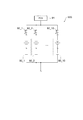
- FIG. 9 is a diagram for explaining the charging control method that the inventors of the present application studied prior to the present application.
- switches 92_1 to 92_10 are provided between the storage battery arrays 90_1 to 90_10 and the PCS 91, and the storage batteries that have been uniformly charged are completed. This is a method of preventing overcharge of each of the storage battery columns 90_1 to 90_10 by disconnecting the columns 90_1 to 90_10 from the PCS 91.
- the suffix of the reference numeral may be omitted and the storage battery column 90 and the like may be referred to, unless the storage battery columns 90_1 to 90_10 and the switches 92_1 to 92_10 are particularly distinguished.
- switches 92_1 to 92_10 are arranged between the storage battery columns 90_1 to 90_10 and the PCS 91, respectively.
- switches 92_1 to 92_10 are turned on to charge all the storage battery columns 90_1 to 90_10.
- the charging states of the storage battery arrays 90_1 to 90_10 are monitored.
- the switch 92 connected to the storage battery array 90 that has been determined to have completed uniform charging is turned off, and the storage battery array 90 is disconnected from the PCS 91.
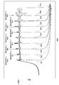
- FIG. 10 is a diagram showing changes in the voltage of each storage battery array when the equal charging is controlled by the charging control method examined by the inventors of the present application prior to the present application.
- FIG. 9 In the power storage system 900 including the 10 sets of storage battery columns 90_1 to 90_10 shown in FIG. 9, by controlling the switches 92_1 to 92_10 during constant voltage charging (CV charging) in the uniform charging, FIG.
- the waveforms of the voltages of the storage battery arrays 90_1 to 90_10 when the storage battery arrays 90_1 to 90_9 are disconnected from the PCS 91 at regular time intervals are shown.
- Reference numerals 901 to 909 represent respective voltages of the storage battery rows 90_1 to 90_9 after disconnection, and reference numeral 910 represents voltages of the remaining storage battery rows 90_1 to 90_10 connected to the PCS 91.
- the inventors of the present application considered that the cause of this phenomenon is that the impedance of the entire storage battery viewed from the PCS 91 side changes before and after the disconnection of the storage battery column 90.
- the present invention has been made in view of the above-described problems, and an object of the present invention is to provide a power storage system including multiple parallel storage batteries, with a simpler configuration, and to reduce variations in the state of charge between storage battery rows due to equal charging. In addition to suppressing, it is to realize more reliable even charging.
- a power storage system is a multi-parallel storage battery in which a plurality of storage battery rows including at least one lead storage battery cell are connected in parallel, and an AC / DC converter that controls the transfer of electric power to the multi-parallel storage battery.
- a first switch that is provided corresponding to each of the storage battery rows and that is connected in series between the corresponding storage battery row and the AC-DC converter, and that is provided corresponding to each of the storage battery rows and corresponds to the first switch.
- An impedance circuit having a predetermined impedance connected in parallel with the first switch between the storage battery array and the AC / DC converter, and provided corresponding to each storage battery array and connected in series with the impedance circuit.
- a second switch connected in parallel with the first switch together with the impedance circuit, and a state of the storage battery row is monitored for each storage battery row, Switch and a control device for controlling on / off of the second switch, the control device turning on the first switch in a state where the second switch is turned off, and the storage battery from the AC / DC converter.
- the power storage system having the multi-parallel storage battery according to the present invention it is possible to realize more reliable uniform charging with a simpler configuration while suppressing the variation in the charging state between the storage battery rows due to the uniform charging. Become.
- FIG. 6 is a diagram for explaining a charge control method at the time of uniform charging in the power storage system according to the embodiment.
- FIG. 6 is a diagram for explaining a charge control method at the time of uniform charging in the power storage system according to the embodiment.
- FIG. 6 is a diagram for explaining a charge control method at the time of uniform charging in the power storage system according to the embodiment.
- FIG. 6 is a diagram for explaining a charge control method at the time of uniform charging in the power storage system according to the embodiment.
- FIG. 6 is a diagram for explaining a charge control method at the time of uniform charging in the power storage system according to the embodiment.
- FIG. 6 is a diagram for explaining a charge control method at the time of uniform charging in the power storage system according to the embodiment. It is a timing chart which shows the charge current and discharge current of the storage battery row
- SOC charge current and charge state
- a power storage system (100) is a multi-parallel system in which a plurality of storage battery rows (20, 20_1 to 20_n) including at least one lead storage battery cell (200) are connected in parallel.
- a first switch (4A_1 to 4A_n) connected in series and provided corresponding to each of the storage battery trains, and connected in parallel with the first switch between the corresponding storage battery train and the AC / DC converter.
- An impedance circuit (5, 5_1 to 5_n) having a predetermined impedance, and the impedance circuit provided corresponding to each of the storage battery rows and connected in series with the impedance circuit, A second switch (4B_1 to 4B_n), both of which are connected in parallel with the first switch, and a state of the storage battery row are monitored for each storage battery row, and ON / OFF of the first switch and the second switch is controlled.
- a control device (1) for controlling the storage battery by supplying power from the AC / DC conversion device to the storage battery train by turning on the first switch with the second switch turned off.
- the second switch of the storage battery row that is determined to be equal charge is determined for each of the storage battery row is determined whether the equal charge is completed while performing the equal charge to fully charge the row.
- the power storage system is characterized in that the first switch of the storage battery row is turned off in a state in which the battery is turned on.
- the impedance circuit may include resistors (R, R1, R2).
- the impedance circuit may include a capacitor (C).
- a charge control method is a multi-parallel storage battery (2) in which a plurality of storage battery rows (20_1 to 20_n) including at least one lead storage battery cell (200) are connected in parallel.
- An AC / DC converter (3) that controls the transfer of electric power to and from the multi-parallel storage battery, and the AC / DC conversion device (3) provided corresponding to each of the storage battery arrays, and connected in series between the corresponding AC storage battery array and the AC / DC conversion device.
- a first switch (4A_1 to 4A_n) is provided corresponding to each of the storage battery trains, and has a predetermined impedance connected in parallel with the first switch between the corresponding storage battery train and the AC / DC converter.
- Impedance circuits (5, 5_1 to 5_n) are provided corresponding to each of the storage battery rows, are connected in series with the impedance circuit, and are connected together with the impedance circuit to the first switch.
- Second switch (4B_1 to 4B_n) connected in parallel with the switch, and a control device for monitoring the state of the storage battery train for each storage battery train and controlling ON / OFF of the first switch and the second switch.
- (1) is a charging control method for the multi-parallel storage battery in an electricity storage system including (1). In the present charging control method, the control device turns on the first switch in a state where the second switch is turned off to supply electric power from the AC / DC converter to the storage battery train, thereby fully charging the storage battery train.
- the device further includes a third step (S3, S4) of turning off the first switch in a state where the second switch of the storage battery array that is determined to have completed the equalized charging is turned on.
- the impedance circuit may include resistors (R, R1, R2).
- the impedance circuit may include a capacitor (C).
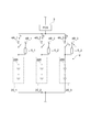
- FIG. 1 is a diagram showing a configuration of a power storage system according to an embodiment of the present invention.
- the electricity storage system 100 shown in the figure is an electricity storage system including a lead-acid battery for cycle use, for example.
- the power storage system 100 supplies power to the load 6 from the power supply unit 7 (commercial power supply) normally, and supplies power from the lead storage battery for power supply backup to the load 6 when a power failure occurs.
- the power supply unit 7 commercial power supply
- the power supply unit 7 is a functional unit that supplies power to the power storage system 100 and the load 6.
- the power supply unit 7 is, for example, a commercial power source.
- the power supply unit 7 may have a power generation facility that generates electric power based on renewable energy such as photovoltaic power generation (PV).
- PV photovoltaic power generation
- the power storage system 100 includes a storage battery module 2, an AC / DC converter 3, switches 4A_1 to 4A_n (n is an integer of 2 or more), switches 4B_1 to 4B_n, impedance circuits 5_1 to 5_n, and a controller 1.
- switch 4A the suffixes of the reference numerals may be omitted and may be referred to as “switch 4A” and the like unless otherwise specified for the switches 4A_1 to 4A_n, the switches 4B_1 to 4B_n, the impedance circuits 5_1 to 5_n, and the like.
- the storage battery module 2 includes a lead storage battery configured to be able to charge and discharge electric power.
- the storage battery module 2 is a multi-parallel storage battery in which a plurality of storage battery rows including at least one lead storage battery cell are connected in parallel.
- the storage battery module 2 has a structure in which a plurality of storage battery rows 20_1 to 20_n in which m (m is an integer of 1 or more) lead storage battery cells 200 are connected in series are connected in parallel. have.
- the storage battery module 2 is also referred to as "multi-parallel storage battery 2".
- the storage battery module 2 includes a voltage sensor 201 that measures the output voltage (storage voltage) of each of the storage battery arrays 20_1 to 20_n and a current sensor 202 that measures the charging current and the discharge current of each of the storage battery arrays 20_1 to 20_n.
- the columns 20_1 to 20_n are provided.
- the AC / DC converter (hereinafter, also referred to as “PCS (Power Conditioning System)”) 3 is controlled by the controller 1 described later, and mutually converts electric power between the power supply unit 7, the storage battery module 2, and the load 6.
- the power conversion unit controls the transfer of power among the power supply unit 7, the storage battery module 2, and the load 6.
- the PCS 3 converts alternating current power (AC) from the power supply unit 7 into direct current power (DC) and supplies it to the storage battery module 2.
- the PCS 3 includes, for example, a DC / DC converter, an AC / DC converter (AC / DC), and a switch circuit.
- the switches 4A_1 to 4A_n are components that switch connection and disconnection between the PCS 3 and the multi-parallel storage battery 2. As shown in FIG. 1, the switches 4A_1 to 4A_n are provided corresponding to the storage battery rows 20_1 to 20_n, and are connected in series between the corresponding storage battery rows 20_1 to 20_n and the PCS 3.
- the switches 4A_1 to 4A_n are electromagnetic switches (relays), for example.
- the switches 4B_1 to 4B_n are components that switch connection and disconnection of the impedance circuit 5 between the PCS 3 and the multi-parallel storage battery 2.
- the switches 4B_1 to 4B_n are provided corresponding to each of the storage battery rows 20_1 to 20_n, and are connected in series between the corresponding storage battery rows 20_1 to 20_n and the PCS 3.
- the switches 4B_1 to 4B_n are connected in series with the corresponding impedance circuits 5_1 to 5_n, and are connected in parallel with the corresponding impedance circuits 5_1 to 5_n and the corresponding switches 4A_1 to 4A_n.
- the switches 4B_1 to 4B_n are electromagnetic switches (relays), for example.
- the impedance circuits 5_1 to 5_n are circuits having a predetermined impedance.
- the impedance circuits 5_1 to 5_n are provided corresponding to each of the storage battery rows 20_1 to 20_n.
- the impedance circuits 5_1 to 5_n are connected in series with the corresponding switches 4B_1 to 4B_n between the corresponding storage battery arrays 20_1 to 20_n and the PCS 3, and are connected in parallel with the switches 4A_1 to 4A_n together with the switches 4B_1 to 4B_n. .
- the impedance circuit 5 is not particularly limited in its circuit configuration as long as it has a predetermined impedance.
- the impedance circuit 5 may include at least one of a resistor, a capacitor, and an inductor, and may be designed so that the impedance of the entire impedance circuit 5 has a predetermined value.
- FIG. 2A and 2B are diagrams showing an example of the configuration of the impedance circuit 5.
- the impedance circuit 5 may be composed of a resistor (element) R, or as shown in FIG. 2B, may include a resistor and at least one capacitor.
- the capacitor is connected in parallel with the resistor.
- FIG. 2B shows an impedance circuit 5 having a resistor R1, a capacitor C connected in parallel with the resistor R1, and a resistor R1 and a resistor R2 connected in series with the capacitor C.
- the control device 1 is a device that performs overall control of the entire power storage system 100.
- the control device 1 monitors the states of the storage battery columns 20_1 to 20_n for each of the storage battery columns 20_1 to 20_n, and can individually control ON / OFF of the switches 4A_1 to 4A_n and the switches 4B_1 to 4B_n.
- the control device 1 includes a monitoring unit 11, a storage battery management unit 12, and a switch control unit 13.
- the monitoring unit 11 is a data processing device that sequentially acquires physical quantities measured by the voltage sensor 201 and the current sensor 202 of the multi-parallel storage battery 2 and monitors the state of the multi-parallel storage battery 2 based on the physical quantity.
- the monitoring unit 11 is, for example, a BMU (Battery Management Unit).
- the storage battery management unit 12 is a device that manages overall control of each component of the power storage system 100.
- the storage battery management unit 12 is, for example, an EMS (Energy Management System).
- the storage battery management unit 12 drives the PCS 3 to control charging / discharging of the multi-parallel storage battery 2.
- the storage battery management unit 12 uses multiple charging systems such as a constant current-constant voltage charging (CCCV) system and a constant power-constant voltage charging system based on the monitoring result of the multi-parallel storage battery 2 by the monitoring unit 11. Perform 2 equal charging.
- CCCV constant current-constant voltage charging
- the constant current-constant voltage charging (CCCV) method refers to starting the charging of the storage battery arrays 20_1 to 20_n with a constant current, and after the voltage of the storage battery arrays 20_1 to 20_n reaches a predetermined voltage, the storage battery array with a constant voltage. This is a charging method for charging 20_1 to 20_n.
- the constant power--constant voltage charging method is to start charging the storage battery arrays 20_1 to 20_n with constant power, and after the voltage of the storage battery arrays 20_1 to 20_n reaches a predetermined voltage, the storage battery arrays 20_1 to 20_n are driven with constant voltage. It is a charging method for charging.
- the switch control unit 13 is a functional unit that switches on / off of the switches 4A_1 to 4A_n and the switches 4B_1 to 4B_n according to an instruction from the monitoring unit 11 or the storage battery management unit 12. For example, when the switches 4A_1 to 4A_n and the switches 4B_1 to 4B_n are relays, the switch control unit 13 generates a drive signal for switching on / off of the relays according to an instruction from the monitoring unit 11 or the storage battery management unit 12. Is a signal generation circuit for
- the monitoring unit 11 and the storage battery management unit 12 are, for example, as hardware resources, a processor such as a CPU (Central Processing Unit), a storage device such as a RAM (Random Access Memory) or a ROM (Read Only Memory), and an I / F.
- a processor such as a CPU (Central Processing Unit)
- a storage device such as a RAM (Random Access Memory) or a ROM (Read Only Memory)
- I / F I/ F.
- a data processing device computer having a peripheral circuit such as a circuit
- the processor executes various operations according to a program stored in the storage device to control the peripheral circuit and the like.
- the control device 1 periodically executes equal charging to fully charge the storage battery rows 20_1 to 20_n of the multi-parallel storage battery 2 in order to prevent deterioration of the lead storage battery that constitutes the multi-parallel storage battery 2.
- the control device 1 turns on the switches 4A_1 to 4A_n with the switches 4B_1 to 4B_n turned off to supply electric power from the PCS 3 to the storage battery columns 20_1 to 20_n to fully charge the storage battery columns 20_1 to 20_n. In addition to performing the equal charge, it is determined whether or not the equal charge is completed for each of the storage battery columns 20_1 to 20_n, and the switches 4B_1 to 4B_n of the storage battery columns 20_1 to 20_n that are determined to be equalized are turned on. The switches 4A_1 to 4A_n in the columns 20_1 to 20_n are turned off.
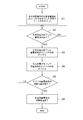
- FIG. 3 is a flow chart showing a flow of a charge control method at the time of uniform charging in the power storage system 100.
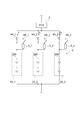
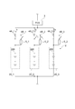
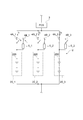
- 4A to 4D are diagrams for describing a charge control method at the time of uniform charging in power storage system 100.
- the charging currents of the storage battery arrays 20_1 to 20_3 during the uniform charging are I1, I2, and I3, respectively, and I2> I1> I3 due to variations in the characteristics of the storage battery arrays 20_1 to 20_3.
- the voltage sensor 201 and the current sensor 202 are not shown in FIGS. 4A to 4D.
- the control device 1 controls the switches 4A_1 to 4A_3 and the switches 4B_1 to 4B_3 to supply electric power from the PCS 3 to the storage battery columns 20_1 to 20_3, so that the storage battery columns 20_1 to 20_3 are uniformly charged. Is started (step S1).
- the monitoring unit 11 requests the storage battery management unit 12 to execute equal charge.
- the storage battery management unit 12 first turns off the switches 4B_1 to 4B_3 via the switch control unit 13 (or confirms that they are off).
- the storage battery management unit 12 turns on (or confirms that it is turned on) the switches 4A_1 to 4A_3 via the switch control unit 13.
- the storage battery management unit 12 drives the PCS 3 so as to perform uniform charging by a predetermined charging method (for example, constant current-constant voltage charging method), and starts power supply to the storage battery rows 20_1 to 20_3.
- a predetermined charging method for example, constant current-constant voltage charging method
- the control device 1 determines whether or not there are the storage battery rows 20_1 to 20_3 that have been uniformly charged (step S2). Specifically, the monitoring unit 11 determines, based on the measurement result of the voltage (output voltage) and current of each of the storage battery arrays 20_1 to 20_3 acquired from the voltage sensor 201 and the current sensor 202 of each of the storage battery arrays 20_1 to 20_3. It is determined whether the uniform charging of 20_1 to 20_3 is completed. Note that a specific determination method will be described later.
- step S2 when there is no storage battery row 20_1 to 20_3 that has been uniformly charged, the control device 1 continues to charge each storage battery row 20_1 to 20_3 evenly.
- step S2 if there are storage battery rows 20_1 to 20_3 that have been uniformly charged, the control device 1 turns on the switches 4B_1 to 4B_3 of the storage battery rows 20_1 to 20_3 that have been uniformly charged (step S3). .
- the storage battery train 20_2 having the largest charging current I2 is fully charged first, and is equalized. Charging is completed.
- the monitoring unit 11 determines that the equal charging of the storage battery row 20_2 is completed, the monitoring unit 11 notifies the storage battery management unit 12 of that fact.
- the storage battery management unit 12 instructs the switch control unit 13 to close (turn on) the switch 4B_2, and the switch control unit 13 closes the switch 4B_2 as illustrated in FIG. 4B.
- the control device 1 turns off the switches 4A_1 to 4A_3 of the storage battery arrays 20_1 to 20_3 for which the equal charging has been completed (step S4).
- the storage battery management unit 12 confirms that the switch 4B_2 is in the ON state, and then instructs the switch control unit 13 to perform the open control (OFF) of the switch 4A_2.
- the switch control unit 13 controls the opening of the switch 4A_2.
- the impedance value of the storage battery array 20_2 viewed from the PCS3 side is higher than the impedance values of the other storage battery arrays 20_1 and 20_3. Therefore, by setting the impedance of the impedance circuit 5_2 to an appropriate value, the current I2 flowing through the storage battery array 20_2 can be suppressed to almost 0A. That is, it is possible to stop charging the storage battery array 20_2.
- the parameter (impedance) of the entire storage battery (multi-parallel storage battery 2) viewed from the PCS3 at this time is compared to the case where the storage battery row 20_2 is completely disconnected from the PCS3 as in the above-described previous study example (see FIG. 9). Therefore, it does not change significantly. That is, by setting the impedance of the impedance circuit 5_2 to an appropriate value, it is possible to suppress the change in the impedance of the entire storage battery viewed from the PCS 3 before and after the storage battery array 20_2 is disconnected (before and after the switching of the switches 4A_2 and 4B_2). As a result, it is possible to favorably adjust the voltage and current of the remaining storage battery arrays 20_1 and 20_3 that have not been fully charged during uniform charging.
- control device 1 determines whether or not the equal charging of all the storage battery rows 20_1 to 20_3 has been completed (step S5).
- the process returns to step S2, and the processes from step S2 to step S5 described above are executed again.
- the storage battery row 20_1 is fully charged next to the storage battery row 20_2.
- the monitoring unit 11 determines that the equal charging of the storage battery row 20_1 is completed, the monitoring unit 11 notifies the storage battery management unit 12 of that fact.
- the storage battery management unit 12 instructs the switch control unit 13 to close (turn on) the switch 4B_1, and as shown in FIG. 4C, the switch control unit 13 that has received the instruction switches the switch 4B_1. 4B_1 is controlled to be closed, and the impedance circuit 5_1 is connected between the storage battery array 20_1 and the PCS3.
- the storage battery management unit 12 instructs the switch control unit 13 to open control (OFF) the switch 4A_1, and as shown in FIG. 4C, The switch control unit 13 controls the switch 4A_1 to open.
- the impedance of the storage battery column 20_1 seen from the PCS3 side is the same as that of the other storage battery column 20_3 as in the case of the storage battery column 20_2 described above. It is higher than the impedance, and it is possible to suppress the change in the impedance of the entire storage battery viewed from the PCS 3 before and after the disconnection of the storage battery array 20_1 (before and after the switching of the switches 4A_1 and 4B_1).
- the impedance of the impedance circuit 5_1 it is possible to suppress the current I1 flowing through the storage battery array 20_1 to approximately 0 A and prevent overcharging of the storage battery array 20_3, and it has not reached full charge. It is possible to satisfactorily control the voltage and current during the uniform charging of the remaining storage battery array 20_3. Immediately after this, since the equal charge of the storage battery row 20_3 is still continuing, the process returns to step S2 again.
- the monitoring unit 11 notifies the storage battery management unit 12 that the equal charging of the storage battery row 20_3 has been completed. Receiving the notification, the storage battery management unit 12 instructs the switch control unit 13 to close (turn on) the switch 4B_3, and as illustrated in FIG. 4D, the switch control unit 13 controls the switch 4B_3 to close. Then, the impedance circuit 5_3 is connected between the storage battery array 20_3 and the PCS3.
- the storage battery management unit 12 confirms that the switch 4B_3 is in the ON state, and then instructs the switch control unit 13 to perform the open control (OFF) of the switch 4A_3, and as illustrated in FIG. 4D.
- the switch control unit 13 controls the opening of the switch 4A_3 to disconnect the storage battery column 20_3 from the PCS3. As a result, the uniform charging of all the storage battery rows 20_1 to 20_3 is completed.
- step S5 When it is determined in step S5 that the equal charging of all the storage battery rows 20_1 to 20_3 is completed, the control device 1 ends the control for equal charging of the multi-parallel storage batteries 2 (step S6).
- the multi-parallel storage battery 2 is uniformly charged according to the above procedure.
- the control device 1 controls the switches 4A_1 to 4A_3 of the storage battery columns 20_1 to 20_3 to be closed (ON), and then controls the switches 4B_1 to 4B_3 of the storage battery columns 20_1 to 20_3 to be opened (OFF), Control for returning the power storage system 100 to the original state is performed.
- the control device 1 calculates the integrated value of the charging current of the storage battery row 20 after the completion of the previous equalization charge and the discharge current of the storage battery row 20 after the completion of the lastly performed equalization charge. When the ratio with the integrated value reaches a predetermined value, it is determined that the equal charging of the storage battery row 20 is completed.
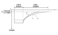
- FIG. 5 is a timing chart showing a charging current and a discharging current of the storage battery row 20 (lead storage battery) at the time of uniform charging.
- the vertical axis represents current and the horizontal axis represents time.
- reference numeral 302 represents a charging current of the storage battery row 20
- reference numeral 303 represents a discharging current of the storage battery row 20.
- the monitoring unit 11 of the control device 1 starts integration of the charging current and the discharging current for each of the storage battery rows 20_1 to 20_n at the timing when the uniform charging is completed. For example, in FIG. 5, at time t31 when the uniform charging is completed, the monitoring unit 11 starts the integration of the charging currents of the storage battery columns 20_1 to 20_n and the integration of the discharge currents of the storage battery columns 20_1 to 20_n. .
- the monitoring unit 11 determines whether or not the calculated ratio reaches the ratio reference value for each of the storage battery columns 20_1 to 20_n.
- the ratio reference value is a reference value for determining the end of the constant voltage charging period in the uniform charging.
- uniform charging is performed by overcharging so that the discharge capacity is 100% or more (for example, 104%). Therefore, the ratio reference value is preferably set to a value exceeding 100%, for example, a value in the range of 101% to 104%.
- the charging current tends to decrease as it approaches full charge. Therefore, it is possible to detect the completion of the uniform charging by monitoring the charging current for each storage battery row 20 during the constant voltage charging period in the uniform charging. For example, the monitoring unit 11 determines that the uniform charging is completed when the charging current of each of the storage battery arrays 20_1 to 20_n decreases and reaches a predetermined threshold value Ith during the constant voltage charging period.
- the charging current I1 of the storage battery string 20_1 next reaches the threshold value Ith.
- the monitoring unit 11 determines that the equal charging of the storage battery array 20_1 has been completed.
- the charging current I3 of the storage battery array 20_3 next reaches the threshold value Ith.
- the monitoring unit 11 determines that the equal charging of the storage battery row 20_3 has been completed.
- the power storage system 100 is provided in correspondence with the multi-parallel storage battery 2 in which a plurality of storage battery arrays 20_1 to 20_n including at least one lead storage battery cell 200 are connected in parallel and the storage battery arrays 20_1 to 20_n. And the switches 4A_1 to 4A_n connected in series between the corresponding storage battery array 20 and the PCS 3, and the impedance circuits 5_1 to 5_n provided corresponding to the storage battery arrays 20_1 to 20_n in series.
- the controller 4 includes switches 4B_1 to 4B_n connected in parallel with the switches 4A_1 to 4A_n as well as 5_1 to 5_n.
- the control device 1 turns on the switch 4A with the switch 4B turned off to perform the equal charge, and also turns on the switch 4A with the switch 4B of the storage battery row 20 determined to have completed the equal charge turned on. Turn off.
- the impedance of the impedance circuit 5_3 is set to an appropriate value, the current I3 flowing through the storage battery array 20_3 can be suppressed to approximately 0 A, so that the charging of the storage battery array 20 is substantially stopped. Therefore, it is possible to prevent overcharge of the storage battery row 20 that has been uniformly charged.
- the power storage system 100 realizes switching between supply and cutoff of power from the PCS 3 to each of the storage battery arrays 20_1 to 20_n at the time of even charging by the switches 4A_1 to 4A_n and the switches 4B_1 to 4B_n, the above-described Patent Document 1 Unlike the related art, there is no need to separately provide a complicated charge / discharge control device for adjusting the charge / discharge amount of each storage battery array for each storage battery array, and the increase in the cost of the power storage system is suppressed as compared with the related art. be able to.
- the impedance of the impedance circuit 5 by setting the impedance of the impedance circuit 5 to an appropriate value, the parameters (impedance) of the entire storage battery (multi-parallel storage battery 2) viewed from the PCS 3 side before and after the parallel disconnection of the storage battery row 20 is completed.
- the change of can be suppressed.
- the PCS 3 it becomes possible for the PCS 3 to appropriately control the voltage and the charging current of the storage battery array 20 during the uniform charging. That is, it is possible to effectively suppress the fluctuation of the voltage that occurs when the storage battery array is disconnected as shown in FIG. 10 described above, and to control the voltage so as not to exceed the upper limit voltage.
- the impedance of the impedance circuit 5 is preferably set to a value based on the voltage value and the current value of the storage battery array 20 during constant voltage charging in the uniform charging. The details will be described below.
- the impedance value of the impedance circuit 5 connected between the storage battery array and the PCS which is determined to have completed the uniform charging, is a value based on the voltage value and the current value of the storage battery array during the constant voltage charging of the uniform charging ( (Voltage value divided by current value).
- an appropriate value may be selected according to the control condition of the PCS 3 and the value may be set as the impedance of the impedance circuit 5.
- a value obtained by multiplying the value of the internal impedance of 20 by a coefficient may be set as the impedance of the impedance circuit 5.
- the impedance of the impedance circuit 5 As described above, by setting the impedance of the impedance circuit 5 to an appropriate value, it becomes possible to suppress the charging current flowing in the storage battery row in which the uniform charging is completed to almost 0 A after switching the switches 4A and 4B, and It is possible to appropriately control the voltage and the current of the storage battery train during the uniform charging by the PCS3 by suppressing the change in the impedance of the entire storage battery viewed from the PCS3 side before and after the disconnection of the storage battery train 20 (before and after the connection of the impedance circuit 5). It will be possible.
- a uniform charging method such as a constant current-constant voltage charging method or a constant power-constant voltage charging method that performs constant voltage charging just before the end of uniform charging, more easily and accurately, It is possible to determine whether or not equal charge is completed for each storage battery row 20.
- first perform constant current charging repeat constant current charging at a current value lower than the previous current value after the storage battery voltage reaches a predetermined threshold value multiple times, and finally perform constant current charging at a predetermined voltage value.
- It may be a multi-stage charging method in which voltage charging is performed to restore the lead storage battery to a fully charged state.
Landscapes
- Engineering & Computer Science (AREA)
- Power Engineering (AREA)
- Charge And Discharge Circuits For Batteries Or The Like (AREA)
Abstract
Description
先ず、本願において開示される発明の代表的な実施の形態について概要を説明する。なお、以下の説明では、一例として、発明の構成要素に対応する図面上の参照符号を、括弧を付して記載している。
以下、本発明の実施の形態の具体例について図を参照して説明する。なお、以下の説明において、各実施の形態において共通する構成要素には同一の参照符号を付し、繰り返しの説明を省略する。また、図面は模式的なものであり、各要素の寸法の関係、各要素の比率などは、現実と異なる場合があることに留意する必要がある。図面の相互間においても、互いの寸法の関係や比率が異なる部分が含まれている場合がある。
図1は、本発明の一実施の形態に係る蓄電システムの構成を示す図である。
同図に示される蓄電システム100は、例えばサイクルユースの鉛蓄電池を備えた蓄電システムである。蓄電システム100は、例えば、通常時に電力供給部7(商用電源)から負荷6に給電し、停電の発生時には、電源バックアップ用の鉛蓄電池から負荷6に給電する。
図1に示すように、スイッチ4B_1~4B_nは、蓄電池列20_1~20_n毎に対応して設けられ、対応する蓄電池列20_1~20_nとPCS3との間に直列に接続されている。具体的には、スイッチ4B_1~4B_nは、対応するインピーダンス回路5_1~5_nと直列に接続され、対応するインピーダンス回路5_1~5_nとともに対応するスイッチ4A_1~スイッチ4A_nと並列に接続されている。スイッチ4B_1~4B_nは、例えば電磁スイッチ(リレー)である。
図2Aに示すように、インピーダンス回路5は、抵抗(素子)Rで構成されていてもよいし、図2Bに示すように、抵抗と、少なくとも一つのキャパシタとを含んでいてもよい。ここで、キャパシタは抵抗と並列に接続される。例えば、図2Bには、抵抗R1と、抵抗R1に並列に接続されたキャパシタCと、抵抗R1およびキャパシタCと直列に接続された抵抗R2とを有するインピーダンス回路5が示されている。
具体的に、蓄電池管理部12は、PCS3を駆動することにより、多並列蓄電池2の充放電制御を行う。例えば、蓄電池管理部12は、監視部11による多並列蓄電池2の監視結果に基づいて、定電流―定電圧充電(CCCV)方式や定電力―定電圧充電方式等の各種充電方式で多並列蓄電池2の均等充電を実行する。
例えば、スイッチ4A_1~4A_nおよびスイッチ4B_1~4B_nがリレーである場合、スイッチ制御部13は、監視部11または蓄電池管理部12からの指示に応じてリレーのオン/オフを切り替えるための駆動信号を生成する信号生成回路である。
この直後は、まだ蓄電池列20_3の均等充電が継続しているため、再びステップS2に戻る。
これにより、全ての蓄電池列20_1~20_3の均等充電が完了する。
本実施の形態に係る均等充電の完了の判定方法として、以下に2つの例を示す。
第1の例として、制御装置1は、前回実施した均等充電が完了してからの蓄電池列20の充電電流の積算値と前回実施した均等充電が完了してからの蓄電池列20の放電電流の積算値との比率が所定値となった場合に、蓄電池列20の均等充電が完了したと判定する。
第2の例として、制御装置1は、均等充電における定電圧によって蓄電池列20を充電する定電圧充電期間において、蓄電池列20の充電電流が低下して所定値となった場合に、蓄電池列20の均等充電が完了したと判定する。
上述したように、蓄電池列20_1~20_3は、温度や鉛蓄電池セル200自体の特性(内部抵抗)により、定電流充電時の充電電流にばらつきが発生する可能性がある。例えば、上述の例のようにI2>I1>I3となった場合を考える。
以上、本発明者らによってなされた発明を実施の形態に基づいて具体的に説明したが、本発明はそれに限定されるものではなく、その要旨を逸脱しない範囲において種々変更可能であることは言うまでもない。
Claims (6)
- 少なくとも一つの鉛蓄電池セルを含む蓄電池列を複数並列に接続した多並列蓄電池と、
前記多並列蓄電池の電力の授受を制御する交直変換装置と、
前記蓄電池列毎に対応して設けられ、対応する前記蓄電池列と前記交直変換装置との間に直列に接続された第1スイッチと、
前記蓄電池列毎に対応して設けられ、対応する前記蓄電池列と前記交直変換装置との間に前記第1スイッチと並列に接続された所定のインピーダンスを有するインピーダンス回路と、
前記蓄電池列毎に対応して設けられ、前記インピーダンス回路と直列に接続され、当該インピーダンス回路とともに前記第1スイッチと並列に接続される第2スイッチと、
前記蓄電池列の状態を前記蓄電池列毎に監視し、前記第1スイッチおよび前記第2スイッチのオン/オフを制御する制御装置と、を備え、
前記制御装置は、前記第2スイッチをオフした状態で前記第1スイッチをオンして前記交直変換装置から前記蓄電池列へ電力を供給することにより、前記蓄電池列を満充電状態にするための均等充電を行うとともに、前記蓄電池列毎に前記均等充電が完了したか否かを判定し、前記均等充電が完了したと判定した前記蓄電池列の前記第2スイッチをオンした状態で当該蓄電池列の前記第1スイッチをオフする
ことを特徴とする蓄電システム。 - 請求項1に記載の蓄電システムにおいて、
前記インピーダンス回路は、抵抗を含む
ことを特徴とする蓄電システム。 - 請求項1に記載の蓄電システムにおいて、
前記インピーダンス回路は、キャパシタを含む
ことを特徴とする蓄電システム。 - 少なくとも一つの鉛蓄電池セルを含む蓄電池列を複数並列に接続した多並列蓄電池と、前記多並列蓄電池の電力の授受を制御する交直変換装置と、前記蓄電池列毎に対応して設けられ、対応する前記蓄電池列と前記交直変換装置との間に直列に接続された第1スイッチと、前記蓄電池列毎に対応して設けられ、対応する前記蓄電池列と前記交直変換装置との間に前記第1スイッチと並列に接続された所定のインピーダンスを有するインピーダンス回路と、前記蓄電池列毎に対応して設けられ、前記インピーダンス回路と直列に接続され、当該インピーダンス回路とともに前記第1スイッチと並列に接続される第2スイッチと、前記蓄電池列の状態を前記蓄電池列毎に監視し、前記第1スイッチおよび前記第2スイッチのオン/オフを制御する制御装置とを備えた蓄電システムにおける前記多並列蓄電池の充電制御方法であって、
前記制御装置が、前記第2スイッチをオフした状態で前記第1スイッチをオンして前記交直変換装置から前記蓄電池列へ電力を供給することにより、前記蓄電池列を満充電状態にするための均等充電を開始する第1ステップと、
前記制御装置が、前記蓄電池列毎に前記均等充電が完了したか否かを判定する第2ステップと、
前記制御装置が、前記均等充電が完了したと判定した前記蓄電池列の前記第2スイッチをオンした状態で前記第1スイッチをオフする第3ステップとを含む
ことを特徴とする充電制御方法。 - 請求項4に記載の充電制御方法において、
前記インピーダンス回路は、抵抗を含む
ことを特徴とする充電制御方法。 - 請求項4に記載の充電制御方法において、
前記インピーダンス回路は、キャパシタを含む
ことを特徴とする充電制御方法。
Priority Applications (2)
| Application Number | Priority Date | Filing Date | Title |
|---|---|---|---|
| JP2020552502A JP7097456B2 (ja) | 2018-10-16 | 2019-03-25 | 蓄電システムおよび充電制御方法 |
| CN201980068693.9A CN112913107B (zh) | 2018-10-16 | 2019-03-25 | 蓄电系统以及充电控制方法 |
Applications Claiming Priority (2)
| Application Number | Priority Date | Filing Date | Title |
|---|---|---|---|
| JP2018194959 | 2018-10-16 | ||
| JP2018-194959 | 2018-10-16 |
Publications (1)
| Publication Number | Publication Date |
|---|---|
| WO2020079868A1 true WO2020079868A1 (ja) | 2020-04-23 |
Family
ID=70283807
Family Applications (1)
| Application Number | Title | Priority Date | Filing Date |
|---|---|---|---|
| PCT/JP2019/012335 Ceased WO2020079868A1 (ja) | 2018-10-16 | 2019-03-25 | 蓄電システムおよび充電制御方法 |
Country Status (3)
| Country | Link |
|---|---|
| JP (1) | JP7097456B2 (ja) |
| CN (1) | CN112913107B (ja) |
| WO (1) | WO2020079868A1 (ja) |
Cited By (2)
| Publication number | Priority date | Publication date | Assignee | Title |
|---|---|---|---|---|
| JP2022066110A (ja) * | 2020-10-16 | 2022-04-28 | 古河電池株式会社 | 蓄電システム |
| JP2024521716A (ja) * | 2021-05-20 | 2024-06-04 | イオントラ インコーポレイテッド | バッテリパック充電平衡化のためのシステムおよび方法 |
Citations (2)
| Publication number | Priority date | Publication date | Assignee | Title |
|---|---|---|---|---|
| JPS604350B2 (ja) * | 1974-08-30 | 1985-02-02 | 株式会社構建設計研究所 | 床板工法 |
| JP2012205384A (ja) * | 2011-03-25 | 2012-10-22 | Sanyo Electric Co Ltd | 蓄電池集合体制御システム |
Family Cites Families (6)
| Publication number | Priority date | Publication date | Assignee | Title |
|---|---|---|---|---|
| JP4411146B2 (ja) * | 2004-06-21 | 2010-02-10 | Necインフロンティア株式会社 | 指紋画像取得・照合装置及び方法 |
| JP2011177011A (ja) * | 2010-01-29 | 2011-09-08 | Sanyo Electric Co Ltd | 充電状態調整装置、それを備えたバッテリシステム、電動車両、移動体、電力貯蔵装置および電源装置ならびに充電状態調整処理プログラム |
| EP2738901A1 (en) | 2011-07-29 | 2014-06-04 | Sanyo Electric Co., Ltd | Charge/discharge control system for storage cell assembly |
| JP2014045625A (ja) * | 2012-08-28 | 2014-03-13 | Sanyo Electric Co Ltd | 蓄電システム |
| DE102013211951A1 (de) * | 2013-06-24 | 2014-12-24 | Younicos Ag | Verfahren und Vorrichtung zur Speicherung elektrischer Energie in elektrochemischen Energiespeichern |
| JP6614010B2 (ja) * | 2016-04-22 | 2019-12-04 | 日立化成株式会社 | 蓄電池システム |
-
2019
- 2019-03-25 CN CN201980068693.9A patent/CN112913107B/zh active Active
- 2019-03-25 WO PCT/JP2019/012335 patent/WO2020079868A1/ja not_active Ceased
- 2019-03-25 JP JP2020552502A patent/JP7097456B2/ja active Active
Patent Citations (2)
| Publication number | Priority date | Publication date | Assignee | Title |
|---|---|---|---|---|
| JPS604350B2 (ja) * | 1974-08-30 | 1985-02-02 | 株式会社構建設計研究所 | 床板工法 |
| JP2012205384A (ja) * | 2011-03-25 | 2012-10-22 | Sanyo Electric Co Ltd | 蓄電池集合体制御システム |
Cited By (5)
| Publication number | Priority date | Publication date | Assignee | Title |
|---|---|---|---|---|
| JP2022066110A (ja) * | 2020-10-16 | 2022-04-28 | 古河電池株式会社 | 蓄電システム |
| JP7575911B2 (ja) | 2020-10-16 | 2024-10-30 | 古河電池株式会社 | 蓄電システム |
| JP2024163264A (ja) * | 2020-10-16 | 2024-11-21 | 古河電池株式会社 | 蓄電池監視装置 |
| JP7757490B2 (ja) | 2020-10-16 | 2025-10-21 | 古河電池株式会社 | 蓄電池監視装置 |
| JP2024521716A (ja) * | 2021-05-20 | 2024-06-04 | イオントラ インコーポレイテッド | バッテリパック充電平衡化のためのシステムおよび方法 |
Also Published As
| Publication number | Publication date |
|---|---|
| JPWO2020079868A1 (ja) | 2021-09-09 |
| JP7097456B2 (ja) | 2022-07-07 |
| CN112913107A (zh) | 2021-06-04 |
| CN112913107B (zh) | 2023-08-08 |
Similar Documents
| Publication | Publication Date | Title |
|---|---|---|
| US10056764B2 (en) | Rechargeable battery systems and rechargeable battery system operational methods | |
| US9118191B2 (en) | Cell balancing method, cell balancing device, and energy storage system including the cell balancing device | |
| US9231440B2 (en) | Power supply apparatus and controlling method of the same | |
| US8653792B2 (en) | Power storage system including a plurality of battery modules and on/off devices or voltage converters | |
| US20130187465A1 (en) | Power management system | |
| KR102151652B1 (ko) | 척컨버터 토폴로지를 이용한 리튬이온 전지 셀밸런싱 장치 | |
| JP7317801B2 (ja) | 蓄電システムおよび計測方法 | |
| TWI520409B (zh) | 電池組電壓平衡裝置與方法 | |
| US20180278064A1 (en) | Storage battery management device, method, and computer program product | |
| WO2019188889A1 (ja) | 蓄電システムおよび充電制御方法 | |
| JP2012524517A (ja) | 充電器、電気システム、および充電式電池の充電方法 | |
| JP5314626B2 (ja) | 電源システム、放電制御方法および放電制御プログラム | |
| JP7382940B2 (ja) | 蓄電システムおよび充電制御方法 | |
| JP5861063B2 (ja) | 蓄電装置及び電力供給システム | |
| WO1998052270A1 (en) | Equalization of series-connected cells and batteries | |
| JP7097456B2 (ja) | 蓄電システムおよび充電制御方法 | |
| WO2023238712A1 (ja) | 組電池の充電方法及び蓄電システム | |
| JP2020526165A (ja) | 電池管理 | |
| KR101925113B1 (ko) | 복수의 배터리 유닛들을 포함하는 전지팩의 충전량을 향상시키기 위한 전지팩 충전기 | |
| EP4513710A2 (en) | Battery storage system and method for providing enhanced battery lifetime | |
| La et al. | Dynamic resistance battery equalization for capacity optimization of parallel-connected cells | |
| JP2010263755A (ja) | 充電制御方法 | |
| WO2016127718A1 (zh) | 电池管理系统和电池管理方法 | |
| CN112768793A (zh) | 一种电池组主动均衡补偿方法、装置、系统及电子设备 | |
| WO2023037599A1 (ja) | 蓄電システム、および、その充電制御方法 |
Legal Events
| Date | Code | Title | Description |
|---|---|---|---|
| 121 | Ep: the epo has been informed by wipo that ep was designated in this application |
Ref document number: 19874744 Country of ref document: EP Kind code of ref document: A1 |
|
| ENP | Entry into the national phase |
Ref document number: 2020552502 Country of ref document: JP Kind code of ref document: A |
|
| WWE | Wipo information: entry into national phase |
Ref document number: 2101002041 Country of ref document: TH |
|
| NENP | Non-entry into the national phase |
Ref country code: DE |
|
| 122 | Ep: pct application non-entry in european phase |
Ref document number: 19874744 Country of ref document: EP Kind code of ref document: A1 |