WO2020075479A1 - Hair product manufacturing fixture and sewing machine - Google Patents
Hair product manufacturing fixture and sewing machine Download PDFInfo
- Publication number
- WO2020075479A1 WO2020075479A1 PCT/JP2019/036969 JP2019036969W WO2020075479A1 WO 2020075479 A1 WO2020075479 A1 WO 2020075479A1 JP 2019036969 W JP2019036969 W JP 2019036969W WO 2020075479 A1 WO2020075479 A1 WO 2020075479A1
- Authority
- WO
- WIPO (PCT)
- Prior art keywords
- weft
- guide
- hair
- cord
- shaped portion
- Prior art date
Links
Images


Classifications
-
- D—TEXTILES; PAPER
- D05—SEWING; EMBROIDERING; TUFTING
- D05B—SEWING
- D05B23/00—Sewing apparatus or machines not otherwise provided for
-
- D—TEXTILES; PAPER
- D05—SEWING; EMBROIDERING; TUFTING
- D05B—SEWING
- D05B27/00—Work-feeding means
- D05B27/02—Work-feeding means with feed dogs having horizontal and vertical movements
-
- D—TEXTILES; PAPER
- D05—SEWING; EMBROIDERING; TUFTING
- D05B—SEWING
- D05B33/00—Devices incorporated in sewing machines for supplying or removing the work
- D05B33/02—Devices incorporated in sewing machines for supplying or removing the work and connected, for synchronous operation, with the work-feeding devices of the sewing machine
-
- D—TEXTILES; PAPER
- D05—SEWING; EMBROIDERING; TUFTING
- D05B—SEWING
- D05B35/00—Work-feeding or -handling elements not otherwise provided for
- D05B35/10—Edge guides
Definitions
- the present invention relates to a hair product manufacturing jig and a sewing machine.
- this double weft In order to manufacture this double weft, it is necessary to sew two wefts together with a string-shaped part. However, since the weft is configured flexibly, it is difficult to align the two wefts straight and send them to the sewing machine. Therefore, in the past, when two wefts were sewn together with a string-shaped portion, it was necessary to gradually sew while adjusting the position, and it took a lot of time to manufacture. Furthermore, since many hairs extend from the weft, the hairs may be caught on the sewing machine during the sewing operation. In particular, hair is often caught on the feed dog of the conventional sewing machine, and the work is often interrupted. In this respect, the manufacturing of the double weft has conventionally required a lot of time.
- An object of the present invention is to provide a hair product manufacturing jig and a sewing machine that can easily perform a work of sewing a plurality of wefts.
- a first invention is a hair product manufacturing jig used for manufacturing a hair product by stitching together a first weft (W1) and a second weft (W2), wherein the first weft (W1) ) Is inserted, and the first guide part (12) for guiding the movement of the string-like part (W1a) in the feed direction and the first guide part (12) in the advancing and retracting direction of the sewing needle (1a). 1 is arranged at a position overlapping the guide portion (12), the string-shaped portion (W2a) of the second weft (W2) can be inserted, and the movement of the string-shaped portion (W2a) is guided in the feed direction.
- the part (14) is opened in a second direction opposite to the first direction and the feed is performed.
- a second invention is the hair product manufacturing jig (10) according to the first invention, wherein the slit width of the first slit (12b) is a cord-like portion (W1a) of the first weft (W1). And the slit width of the second slit (14b) is smaller than the thickness of the string-like portion (W2a) of the second weft (W2). It is a hair product manufacturing jig (10).
- 3rd invention is the hair product manufacturing jig (10) as described in 1st invention or 2nd invention, Comprising: 1st extended from the position connected to the said 1st slit (12b) to the said 1st direction
- a first hair guide part (13) having a guide surface (13a) for guiding a hair part (W1b) connected to the cord-shaped part (W1a) of the first weft (W1); Hair having a second guide surface (15a) extending in the second direction from a position connected to the two slits (14b) and connected to the cord-like portion (W2a) of the second weft (W2).
- a hair product manufacturing jig (10) in any one of 1st invention to 3rd invention, Comprising: The said 1st weft (W1) and the said 2nd weft (W2).
- a fifth invention is the hair product manufacturing jig (, 20) according to any one of the first invention to the fourth invention, wherein the first guide portion (12) and the second guide portion (14) are provided.
- a feed dog (20) that feeds at least one of the cord-shaped portion (W1a) of the first weft (W1) and the cord-shaped portion (W2a) of the second weft (W2) guided in the feeding direction.
- the width of the tooth portion (21) of the feed dog (20) is narrower than the width of the first guide portion (12) and the second guide portion (14).
- a sixth invention is a sewing machine (1) including the hair product manufacturing jig (10) according to any one of the first to fifth inventions.
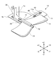
- FIG. 1 is a perspective view showing an embodiment of a sewing machine 1 including a hair product manufacturing jig according to the present invention. It is the perspective view which expanded only the principal part of the sewing machine 1 near the sewing needle 1a.
- FIG. 3 is an exploded perspective view showing the members shown in FIG. 2 separately. It is the figure which looked at the guide jig 10 in the direction shown by the arrow A in FIG. 3 (direction from -Y side to + Y side). It is a figure which shows the 1st weft W1 and the 2nd weft W2.
- FIG. 2 is an enlarged view from the front side ( ⁇ Y side) of a state in which the sewing machine 1 of the present embodiment performs sewing of the string-shaped portion W1a of the first weft W1 and the string-shaped portion W2a of the second weft W2. is there.
- FIG. 1 is a perspective view showing an embodiment of a sewing machine 1 including a hair product manufacturing jig according to the present invention.
- FIG. 2 is an enlarged perspective view of only a main part near the sewing needle 1a of the sewing machine 1.
- FIG. 3 is an exploded perspective view showing the members shown in FIG. 2 separately.
- FIG. 4 is a view of the guide jig 10 viewed in the direction indicated by the arrow A in FIG. 3 (from the ⁇ Y side to the + Y side).
- FIG. 5 is a diagram showing the first weft W1 and the second weft W2. It should be noted that each of the following drawings including FIGS.
- the horizontal direction (right-left direction) orthogonal to each other was defined as the X-axis direction.
- X-axis direction The horizontal direction (right-left direction) orthogonal to each other.
- the sewing machine 1 of the present embodiment is a commercially available sewing machine to which the hair product manufacturing jig (10, 20) is attached. Since the sewing needle 1a and the needle plate 1b are ordinary members included in the sewing machine, detailed description thereof will be omitted.
- the sewing machine 1 of the present embodiment is provided with the hair product manufacturing jig (10, 20), so that the string-like portion W1a of the first weft W1 and the string-like portion W2a of the second weft W2 are sewn together to form a sewing machine 1 Used to produce one hair product (double weft).
- the first weft W1 has a string-shaped portion W1a and a hair portion W1b having one end attached to the string-shaped portion W1a.
- the second weft W2 has the same structure as the first weft W1 and has a string-shaped portion W2a and a hair bristle W2b having one end attached to the string-shaped portion W2a.
- the bristles W1b and W2b are usually provided in a larger number than shown in the figure, they are shown in a simplified manner.
- the first weft W1 and the second weft W2 are conventionally used as one mode of hair attachment, but the sewing machine 1 of the present embodiment connects these two wefts with a string-shaped portion to produce a hair product. (Double weft). By connecting two wefts, this double weft increases the amount of the bristles and facilitates attachment to the ground hair.
- the wearer's ground hair is knitted to form a base called a stove, and a cord-like portion is woven or sewn to the stove.
- the first weft W1 and the second weft W2 may have the same form, or may have different forms such as colors and hairs.
- the above-described method of attaching to the ground hair is an example, and the usage thereof is not limited.
- a guide jig 10 and a feed dog 20 are provided as a hair product manufacturing jig.
- the guide jig 10 is a member having a main configuration as a hair product manufacturing jig, and includes a fixing portion 11, a first guide portion 12, a first hair guide portion 13, and a second guide portion 14. , And the second false hair guide portion 15.
- the guide jig 10 of the present embodiment is configured by welding a metal plate after performing necessary bending, but for example, a part or all of the guide jig 10 may be made of resin, and a similar configuration is possible. Any material may be used as the material.
- the fixing portion 11 is formed in a plate shape parallel to the XY plane and has a long hole 11a that is long in the X-axis direction.
- a screw 40 is passed through the long hole 11 a, and the guide jig 10 is fixed to the sewing machine 1. Since the long hole 11a is configured to be long in the X-axis direction, the guide jig 10 can adjust the fixed position with respect to the sewing machine 1.
- the fixed position of the guide jig 10 in the X-axis direction is adjustable in the present embodiment, for example, it may be adjustable in the Y-axis direction or may be adjustable in both directions.
- the first guide portion 12 is arranged so as to extend in the Y-axis direction in the vicinity of the approximate center of the guide jig 10 in the X-axis direction, and the movement of the cord-shaped portion W1a of the first weft W1 is set in the feeding direction (Y Guide in the axial direction). More specifically, as shown in FIG. 4, the first guide portion 12 is formed in a tubular shape having a substantially rectangular cross section in a cross section orthogonal to the Y axis, and the first guide passage 12a extends in the Y axis direction. It is formed to extend.
- the cord-shaped portion W1a of the first weft W1 is inserted into the first guide passage 12a, and the movement direction of the cord-shaped portion W1a is restricted in the Y-axis direction.
- the first guide portion 12 has a first slit 12b which is open on the ⁇ X side (first direction) and extends in the Y-axis direction (feed direction) over the entire length of the first guide portion 12. are doing.
- the bristles W1b extending from the string-shaped portion W1a are passed through the first slit 12b.
- the slit width of the first slit 12b is configured to be smaller than the thickness of the string-shaped portion W1a of the first weft W1.
- the cord-shaped portion W1a of the first weft W1 does not drop from the inside of the first guide passage 12a through the first slit 12b and is stably guided for its movement.
- the first false hair guide portion 13 has a first guide surface 13a extending from the position connected to the first slit 12b to the ⁇ X side (first direction), and is attached to the string-like portion W1a of the first weft W1. Guide the attached hair portion W1b.
- An inclined surface 13b is formed at an end of the first hair guide portion 13, particularly at an end on the -X side and the -Y side so that the attachment surface of the sewing machine 1 is smoothly connected to the first guide surface 13a. , And the bristles W1b can be smoothly guided to the first guide surface 13a.
- the second guide portion 14 is arranged so as to extend in the Y-axis direction in the vicinity of the approximate center of the guide jig 10 in the X-axis direction, and the movement of the cord-shaped portion W2a of the second weft W2 is set in the feeding direction (Y Guide in the axial direction). More specifically, as shown in FIG. 4, the second guide portion 14 is formed in a tubular shape having a substantially rectangular cross section in a cross section orthogonal to the Y axis, and the second guide passage 14a extends in the Y axis direction. It is formed to extend.
- the cord-shaped portion W2a of the second weft W2 is inserted into the second guide passage 14a, and the movement direction of the cord-shaped portion W2a is restricted in the Y-axis direction.
- the second guide portion 14 has a second slit 14b which is opened on the + X side (second direction) and extends in the Y-axis direction (feeding direction) over the entire length of the second guide portion 14. ing.
- the bristles W2b extending from the string-shaped portion W2a are passed through the second slits 14b.
- the slit width of the second slit 14b is configured to be smaller than the thickness of the string-shaped portion W2a of the second weft W2.
- the second bristle guide portion 15 has a second guide surface 15a extending from the position connected to the second slit 14b to the + X side (second direction), and is connected to the string-shaped portion W2a of the second weft W2.
- the attached hair portion W2b is guided.
- An inclined surface 15b is formed at an end portion of the second hair setting portion 15, particularly an end portion on the + X side and the -Y side so as to be smoothly connected to the second guide surface 15a from the attachment surface of the sewing machine 1,
- the bristles W2b can be smoothly guided to the second guide surface 15a.
- the feed dog 20 is arranged below the needle plate 1b of the sewing machine 1 ( ⁇ Z side).
- the feed dog 20 basically has the same structure as the feed dog provided in the conventional sewing machine, but the structure of the tooth portion 21 is different from the conventional one.
- the needle plate 1b shown in FIG. 3 has the same structure as the conventional structure used with a normal feed dog, but three slits 1ba are lined up in the needle plate 1b in the feeding direction ( It extends in the Y-axis direction).
- the tooth portion of the feed dog is exposed from each of the three slits 1ba, and the cloth can be fed in a wide area. Therefore, the conventional feed dog has three tooth portions corresponding to the three slits 1ba.
- the configuration in which the slit 1ba has three slits is illustrated, but there may be five slits or the like depending on the sewing machine.
- the width b2 of the tooth portion 21 of the feed dog 20 is narrower than the width b1 of the first guide portion 12 and the second guide portion 14. Therefore, although the tooth portion 21 is arranged at a position necessary for feeding the cord-shaped portion W1a of the first weft W1 and the cord-shaped portion W2a of the second weft W2, the hair bristles W1b and the hair bristles are arranged.
- the feed dog 20 may be manufactured by additionally machining what is normally attached to a commercially available sewing machine.
- the needle plate 1b since the needle plate 1b that is normally attached to the sewing machine is used as it is, two of the three slits 1ba arranged side by side are unnecessary. . Therefore, the needle plate 1b may be manufactured with only one slit 1ba and added to a part of the hair product manufacturing jig of the present invention.
- the presser foot 30 is a member for pressing the sewing object (in the present embodiment) the string-shaped portion W1a of the first weft W1 and the string-shaped portion W2a of the second weft W2, and is normally attached to a commercially available sewing machine. You can also use the existing one. Further, it is desirable that the front side ( ⁇ Y side) tip of the presser foot 30 and the back side (+ Y side) tip of the guide jig 10 be as close as possible. Further, it is more desirable to bring the distal end (+ Y side) of the guide jig 10 closer to the advance / retreat position of the sewing needle 1a.
- the presser foot 30 that is normally attached to a commercially available sewing machine is not used, and the presser foot 30 is newly manufactured and configured as a part of a hair product manufacturing jig.
- the presser foot 30 of the present embodiment is configured such that the distance from the hole portion through which the sewing needle 1a advances and retracts to the front ( ⁇ Y side) tip of the presser foot 30 is shorter than a normal presser foot. This makes it possible to more stably sew the cord-shaped portion W1a of the first weft W1 and the cord-shaped portion W2a of the second weft W2.
- the presser foot 30 may be manufactured by additionally modifying what is normally attached to a commercially available sewing machine.
- FIG. 6 is a view of a state in which the string-shaped portion W1a of the first weft W1 and the string-shaped portion W2a of the second weft W2 are sewn together by the sewing machine 1 of the present embodiment as seen from above (+ Z side).
- FIG. 7 is an enlarged view from the front side ( ⁇ Y side) of a state in which the sewing machine 1 of the present embodiment performs sewing of the string-shaped portion W1a of the first weft W1 and the string-shaped portion W2a of the second weft W2. It is the figure seen. 6 and 7 show only the configuration necessary for the explanation. Further, in FIG. 7, the position of the feed dog 20 is shown in a state where the tooth portion 21 is lowered downward.
- the cord-shaped portion W1a of the first weft W1 and the cord-shaped portion W2a of the second weft W2 is inserted into the first guide passage 12a, and the string-shaped portion W2a is inserted into the second guide passage 14a of the second guide portion 14. Further, the hair bristles W1b are arranged on the first hair bristling guide 13 through the first slits 12b, and the hair bristles W2b are arranged on the second hair bristling guide 15 through the second slits 14b.
- the string-shaped portion W1a is restricted from moving in the feed direction (Y-axis direction) without dropping from the first guide passage 12a of the first guide portion 12,
- the string-shaped portion W2a is restricted to the feed direction (Y-axis direction) in the moving direction without dropping from the second guide passage 14a of the second guide portion 14, and the string-shaped portion W1a and the string-shaped portion are sewn at the time of sewing. It is possible to maintain the state in which the position of W2a and the position of W2a are appropriately overlapped with each other, and the work can be easily performed.
- the bristles W1b and the bristles W2b are guided by the first bristles guide 13 and the second bristles guide 15, it is possible to prevent them from being caught by other parts of the sewing machine 1. Furthermore, since the tooth portion 21 of the feed dog 20 is covered with the string-shaped portion W1a and the string-shaped portion W2a and is not exposed, the hair bristles W1b and the hair bristles W2b are caught on the tooth portion 21. Can be prevented.
- the sewing machine 1 of this embodiment since the guide jig 10 and the feed dog 20 as the hair product manufacturing jig are provided, the work of sewing a plurality of wefts can be easily performed. .
- first guide portion 12 and the second guide portion 14 have been described with an example in which the cross-sectional shape is a substantially rectangular shape.
- the cross-sectional shapes of the first guide portion 12 and the second guide portion 14 may be circular or polygonal such as triangular or pentagonal.
- the guide passage may be further overlapped in the vertical direction (Z-axis direction) so that three or four wefts can be sewn together at the same time.
- the guide jig 10 has been described with reference to an example in which the first bristling guide portion 13 and the second bristling guide portion 15 are provided on the left and right sides ( ⁇ X side and + X side). Not limited to this, for example, if there is no configuration in which the false hair portion may be caught in the sewing machine, one of these may be omitted, or both may be omitted.
- Sewing machine 1a Sewing needle 1b Needle plate 1ba Slit 10 Guide jig 11 Fixed part 11a Long hole 12 First guide part 12a First guide passage 12b First slit 13 First hair guide part 13a First guide surface 13b Slope 14th 2 guide part 14a 2nd guide passage 14b 2nd slit 15 2nd false hair guide part 15a 2nd guide surface 15b slope 20 feed tooth 21 tooth part 30 presser foot 40 screw W1 1st weft W1a cord part W1b hair part W2 Second weft W2a String-like portion W2b Bristles
Landscapes
- Engineering & Computer Science (AREA)
- Textile Engineering (AREA)
- Sewing Machines And Sewing (AREA)
Abstract
Provided are: a hair product manufacturing fixture with which a plurality of wefts can be easily sewn together; and a sewing machine. This hair product manufacturing fixture, which is a guide fixture 10 used for manufacturing a hair product by sewing together a first weft W1 and a second weft W2, has: a first guide part 12 into which a string-like portion W1a of the first weft W1 can be inserted and which guides the movement of the string-like portion W1a in a feeding direction; and a second guide part 14 into which a string-like portion W2a of the second weft W2 can be inserted and which guides the movement of the string-like portion W2a in the feeding direction, wherein the second guide part 14 is disposed at a position superposed with the first guide part 12 in the advancing/retreating direction of a sewing needle 1a. The first guide part 12 has a first slit 12b open in a first direction and extending in the feeding direction, and the second guide part 14 has a second slit 14b open in a second direction, which is the opposite direction of the first direction, and extending in the feeding direction.
Description
本発明は、頭髪製品製造治具、ミシンに関するものである。
The present invention relates to a hair product manufacturing jig and a sewing machine.
地毛に対して縫い付けたり、器具で取り付けたりする付け毛が従来から用いられている。付け毛として従来から、多数の毛の一端を紐状部分に取り付けてまとめたウェフト(みの毛)が用いられている。このウェフトは、紐状部分の一方向に毛が延在して取り付けられているものが一般的であったが、近年、2つのウェフトを紐状部分で繋げて、紐状部分の両方向に毛が延在した形態とした新しい形態の頭髪製品(以下、2重ウェフトと呼ぶ)が開発されている。
Hairing that is sewn onto the ground hair or attached with a tool has been used conventionally. Conventionally, wefts (flocks) in which one end of a large number of bristles are attached to a string-shaped portion and gathered together have been used as false hairs. This weft is generally one in which the bristles extend in one direction and are attached, but in recent years, two wefts are connected by a brace to form bristles in both directions. Has developed a new form of hair product (hereinafter referred to as a double weft).
この2重ウェフトを製造するためには、2つのウェフトを紐状部分で縫い合わせることが必要である。しかし、ウェフトは柔軟に構成されていることから、2つのウェフトを真っ直ぐに揃えてミシンに送っていくことが難しかった。したがって、従来は、2つのウェフトを紐状部分で縫い合わせるときには、位置を調整しながら少しずつ縫い進める必要があり、製造に多くの時間がかかっていた。さらに、ウェフトからは多数の毛が延在していることから、縫い作業中に毛がミシンに引っ掛かってしまうことがあった。特に、従来のミシンの送り歯に毛が引っ掛かってしまうことが多く、作業が中断することが多く、この点でも、2重ウェフトの製造には、従来は多くの時間がかかっていた。
In order to manufacture this double weft, it is necessary to sew two wefts together with a string-shaped part. However, since the weft is configured flexibly, it is difficult to align the two wefts straight and send them to the sewing machine. Therefore, in the past, when two wefts were sewn together with a string-shaped portion, it was necessary to gradually sew while adjusting the position, and it took a lot of time to manufacture. Furthermore, since many hairs extend from the weft, the hairs may be caught on the sewing machine during the sewing operation. In particular, hair is often caught on the feed dog of the conventional sewing machine, and the work is often interrupted. In this respect, the manufacturing of the double weft has conventionally required a lot of time.
生地の縫い合わせにおいては、例えば、特許文献1のような生地合せガイドが知られているが、ウェフトの縫い合わせに利用できるガイドは、従来存在していなかった。
For stitching of fabrics, for example, a fabric-matching guide as disclosed in Patent Document 1 is known, but no guide that can be used for stitching a weft has hitherto existed.
本発明の課題は、複数のウェフトを縫い合わせる作業を容易に行なうことができる頭髪製品製造治具、ミシンを提供することである。
An object of the present invention is to provide a hair product manufacturing jig and a sewing machine that can easily perform a work of sewing a plurality of wefts.
本発明は、以下のような解決手段により、前記課題を解決する。なお、理解を容易にするために、本発明の実施形態に対応する符号を付して説明するが、これに限定されるものではない。
The present invention solves the above problems by the following solution means. It should be noted that, for ease of understanding, reference numerals corresponding to the embodiments of the present invention will be given and described, but the present invention is not limited thereto.
第1の発明は、第1のウェフト(W1)と第2のウェフト(W2)とを縫い合わせて頭髪製品を製造するために用いられる頭髪製品製造治具であって、前記第1のウェフト(W1)の紐状部分(W1a)が挿入可能であって、前記紐状部分(W1a)の移動を送り方向に案内する第1案内部(12)と、縫製針(1a)の進退方向で前記第1案内部(12)と重なる位置に配置され、前記第2のウェフト(W2)の紐状部分(W2a)が挿入可能であって、前記紐状部分(W2a)の移動を前記送り方向に案内する第2案内部(14)と、を備え、前記第1案内部(12)は、第1の向きに開口し送り方向に延在する第1スリット(12b)を有し、前記第2案内部(14)は、前記第1の向きとは反対向きの第2の向きに開口し前記送り方向に延在する第2スリット(14b)を有する頭髪製品製造治具(10)である。
A first invention is a hair product manufacturing jig used for manufacturing a hair product by stitching together a first weft (W1) and a second weft (W2), wherein the first weft (W1) ) Is inserted, and the first guide part (12) for guiding the movement of the string-like part (W1a) in the feed direction and the first guide part (12) in the advancing and retracting direction of the sewing needle (1a). 1 is arranged at a position overlapping the guide portion (12), the string-shaped portion (W2a) of the second weft (W2) can be inserted, and the movement of the string-shaped portion (W2a) is guided in the feed direction. And a second guide portion (14) for performing the first guide portion (12), the first guide portion (12) having a first slit (12b) that opens in a first direction and extends in the feed direction. The part (14) is opened in a second direction opposite to the first direction and the feed is performed. A second slit extending in the direction hair product manufacturing jig having (14b) (10).
第2の発明は、第1の発明に記載の頭髪製品製造治具(10)において、前記第1スリット(12b)のスリット幅は、前記第1のウェフト(W1)の紐状部分(W1a)の厚さよりも小さく構成されており、前記第2スリット(14b)のスリット幅は、前記第2のウェフト(W2)の紐状部分(W2a)の厚さよりも小さく構成されていること、を特徴とする頭髪製品製造治具(10)である。
A second invention is the hair product manufacturing jig (10) according to the first invention, wherein the slit width of the first slit (12b) is a cord-like portion (W1a) of the first weft (W1). And the slit width of the second slit (14b) is smaller than the thickness of the string-like portion (W2a) of the second weft (W2). It is a hair product manufacturing jig (10).
第3の発明は、第1の発明又は第2の発明に記載の頭髪製品製造治具(10)において、前記第1スリット(12b)に繋がる位置から前記第1の向きに延在する第1案内面(13a)を有し、前記第1のウェフト(W1)の紐状部分(W1a)に接続された付け毛部(W1b)を案内する第1付け毛案内部(13)と、前記第2スリット(14b)に繋がる位置から前記第2の向きに延在する第2案内面(15a)を有し、前記第2のウェフト(W2)の紐状部分(W2a)に接続された付け毛部(W2b)を案内する第2付け毛案内部(15)と、を備えること、を特徴とする頭髪製品製造治具(10)である。
3rd invention is the hair product manufacturing jig (10) as described in 1st invention or 2nd invention, Comprising: 1st extended from the position connected to the said 1st slit (12b) to the said 1st direction A first hair guide part (13) having a guide surface (13a) for guiding a hair part (W1b) connected to the cord-shaped part (W1a) of the first weft (W1); Hair having a second guide surface (15a) extending in the second direction from a position connected to the two slits (14b) and connected to the cord-like portion (W2a) of the second weft (W2). A second hair guide part (15) for guiding the part (W2b), and a hair product manufacturing jig (10).
第4の発明は、第1の発明から第3の発明までのいずれかに記載の頭髪製品製造治具(10)において、前記第1のウェフト(W1)と前記第2のウェフト(W2)との縫い合わせに用いるミシン(1)に対して当該頭髪製品製造治具(10)を固定する固定部(11)を備えること、を特徴とする頭髪製品製造治具(10)である。
4th invention is a hair product manufacturing jig (10) in any one of 1st invention to 3rd invention, Comprising: The said 1st weft (W1) and the said 2nd weft (W2). A hair product manufacturing jig (10), comprising: a fixing part (11) for fixing the hair product manufacturing jig (10) to the sewing machine (1) used for sewing.
第5の発明は、第1の発明から第4の発明までのいずれかに記載の頭髪製品製造治具(,20)において、前記第1案内部(12)及び前記第2案内部(14)によって案内される前記第1のウェフト(W1)の紐状部分(W1a)及び前記第2のウェフト(W2)の紐状部分(W2a)の少なくとも一方を送り方向へ送る送り歯(20)をさらに含み、前記送り歯(20)の歯部(21)の幅は、前記第1案内部(12)及び前記第2案内部(14)の幅よりも狭いこと、を特徴とする頭髪製品製造治具(10,20)である。
A fifth invention is the hair product manufacturing jig (, 20) according to any one of the first invention to the fourth invention, wherein the first guide portion (12) and the second guide portion (14) are provided. A feed dog (20) that feeds at least one of the cord-shaped portion (W1a) of the first weft (W1) and the cord-shaped portion (W2a) of the second weft (W2) guided in the feeding direction. The width of the tooth portion (21) of the feed dog (20) is narrower than the width of the first guide portion (12) and the second guide portion (14). The ingredients (10, 20).
第6の発明は、第1の発明から第5の発明までのいずれかに記載の頭髪製品製造治具(10)を備えるミシン(1)である。
A sixth invention is a sewing machine (1) including the hair product manufacturing jig (10) according to any one of the first to fifth inventions.
本発明によれば、複数のウェフトを縫い合わせる作業を容易に行なうことができる頭髪製品製造治具、ミシンを提供することができる。
According to the present invention, it is possible to provide a hair product manufacturing jig and a sewing machine that can easily perform a work of sewing a plurality of wefts.
以下、本発明を実施するための最良の形態について図面等を参照して説明する。
The best mode for carrying out the present invention will be described below with reference to the drawings.
(実施形態)
図1は、本発明による頭髪製品製造治具を備えるミシン1の実施形態を示す斜視図である。
図2は、ミシン1の縫製針1a付近の主要部のみを拡大した斜視図である。
図3は、図2中に示された部材を分けて示した分解斜視図である。
図4は、案内治具10を図3中の矢印Aに示す向き(-Y側から+Y側への向き)で見た図である。
図5は、第1のウェフトW1と第2のウェフトW2とを示す図である。
なお、図1から図4を含め、以下に示す各図は、模式的に示した図であり、各部の大きさ、形状は、理解を容易にするために、適宜誇張して示している。
また、以下の説明では、具体的な数値、形状、材料等を示して説明を行うが、これらは、適宜変更することができる。
また、図中には、必要に応じて方向を示すためのX軸、Y軸、Z軸の座標軸を併記した。ミシン1を平面に設置した状態においてミシンの縫製時の送り方向に平行な方向をY軸方向とし、縫製針1aの進退方向(鉛直方向)をZ軸方向とし、Y軸方向及びZ軸方向と直交する水平方向(左右方向)をX軸方向とした。以下の説明では、これら座標軸を用いて説明を行なうので、頭髪製品製造治具単体の説明であっても、ミシン1に対して適正に取り付けられた状態における方向であるものとする。 (Embodiment)
FIG. 1 is a perspective view showing an embodiment of a sewing machine 1 including a hair product manufacturing jig according to the present invention.
FIG. 2 is an enlarged perspective view of only a main part near thesewing needle 1a of the sewing machine 1.
FIG. 3 is an exploded perspective view showing the members shown in FIG. 2 separately.
FIG. 4 is a view of theguide jig 10 viewed in the direction indicated by the arrow A in FIG. 3 (from the −Y side to the + Y side).
FIG. 5 is a diagram showing the first weft W1 and the second weft W2.
It should be noted that each of the following drawings including FIGS. 1 to 4 is a schematic diagram, and the size and shape of each portion are exaggerated as appropriate for easy understanding.
Further, in the following description, specific numerical values, shapes, materials and the like are shown and described, but these can be appropriately changed.
Further, in the drawing, coordinate axes of X-axis, Y-axis, and Z-axis for indicating directions are also shown as necessary. With the sewing machine 1 installed on a plane, the direction parallel to the feed direction during sewing of the sewing machine is the Y-axis direction, the advancing and retracting direction (vertical direction) of thesewing needle 1a is the Z-axis direction, and the Y-axis direction and the Z-axis direction. The horizontal direction (right-left direction) orthogonal to each other was defined as the X-axis direction. In the following description, since these coordinate axes are used for the description, even in the case of the hair product manufacturing jig alone, it is assumed that the direction is in a state where it is properly attached to the sewing machine 1.
図1は、本発明による頭髪製品製造治具を備えるミシン1の実施形態を示す斜視図である。
図2は、ミシン1の縫製針1a付近の主要部のみを拡大した斜視図である。
図3は、図2中に示された部材を分けて示した分解斜視図である。
図4は、案内治具10を図3中の矢印Aに示す向き(-Y側から+Y側への向き)で見た図である。
図5は、第1のウェフトW1と第2のウェフトW2とを示す図である。
なお、図1から図4を含め、以下に示す各図は、模式的に示した図であり、各部の大きさ、形状は、理解を容易にするために、適宜誇張して示している。
また、以下の説明では、具体的な数値、形状、材料等を示して説明を行うが、これらは、適宜変更することができる。
また、図中には、必要に応じて方向を示すためのX軸、Y軸、Z軸の座標軸を併記した。ミシン1を平面に設置した状態においてミシンの縫製時の送り方向に平行な方向をY軸方向とし、縫製針1aの進退方向(鉛直方向)をZ軸方向とし、Y軸方向及びZ軸方向と直交する水平方向(左右方向)をX軸方向とした。以下の説明では、これら座標軸を用いて説明を行なうので、頭髪製品製造治具単体の説明であっても、ミシン1に対して適正に取り付けられた状態における方向であるものとする。 (Embodiment)
FIG. 1 is a perspective view showing an embodiment of a sewing machine 1 including a hair product manufacturing jig according to the present invention.
FIG. 2 is an enlarged perspective view of only a main part near the
FIG. 3 is an exploded perspective view showing the members shown in FIG. 2 separately.
FIG. 4 is a view of the
FIG. 5 is a diagram showing the first weft W1 and the second weft W2.
It should be noted that each of the following drawings including FIGS. 1 to 4 is a schematic diagram, and the size and shape of each portion are exaggerated as appropriate for easy understanding.
Further, in the following description, specific numerical values, shapes, materials and the like are shown and described, but these can be appropriately changed.
Further, in the drawing, coordinate axes of X-axis, Y-axis, and Z-axis for indicating directions are also shown as necessary. With the sewing machine 1 installed on a plane, the direction parallel to the feed direction during sewing of the sewing machine is the Y-axis direction, the advancing and retracting direction (vertical direction) of the
本実施形態のミシン1は、市販されているミシンに、頭髪製品製造治具(10,20)を取り付けたものである。
縫製針1a及び針板1bは、ミシンが備えている通常の部材であるので、詳しい説明は省略する。 The sewing machine 1 of the present embodiment is a commercially available sewing machine to which the hair product manufacturing jig (10, 20) is attached.
Since thesewing needle 1a and the needle plate 1b are ordinary members included in the sewing machine, detailed description thereof will be omitted.
縫製針1a及び針板1bは、ミシンが備えている通常の部材であるので、詳しい説明は省略する。 The sewing machine 1 of the present embodiment is a commercially available sewing machine to which the hair product manufacturing jig (10, 20) is attached.
Since the
本実施形態のミシン1は、頭髪製品製造治具(10,20)を備えることにより、第1のウェフトW1の紐状部分W1aと、第2のウェフトW2の紐状部分W2aとを縫い合わせて1つの頭髪製品(2重ウェフト)を製造するために用いられる。
第1のウェフトW1は、紐状部分W1aと、紐状部分W1aに一端が取り付けられた付け毛部W1bとを有している。
第2のウェフトW2は、第1のウェフトW1と同様な構成をしており、紐状部分W2aと、紐状部分W2aに一端が取り付けられた付け毛部W2bとを有している。
なお、付け毛部W1b、W2bは、通常、図示したものよりも多数設けられているが、簡略化して示している。
第1のウェフトW1及び第2のウェフトW2は、従来から付け毛の一態様として利用されているものであるが、本実施形態のミシン1によりこれら2つのウェフトを紐状部分で繋げて頭髪製品(2重ウェフト)とする。この2重ウェフトは、2つのウェフトが繋げられていることにより、付け毛部の分量を増大し、また、地毛への取り付けを容易にしている。地毛への2重ウェフトの取り付け方としては、例えば、被装着者の地毛を編んでコンローと呼ばれる土台を作り、このコンローへ紐状部分を編み込んだり縫い合わせたりして利用される。なお、第1のウェフトW1及び第2のウェフトW2は、その形態が全く同一のものであってもよいし、色や毛質等が異なるもの同士であってもよい。また、上述した地毛への取り付け方は、一例であって、その利用法を限定するものではない。 The sewing machine 1 of the present embodiment is provided with the hair product manufacturing jig (10, 20), so that the string-like portion W1a of the first weft W1 and the string-like portion W2a of the second weft W2 are sewn together to form a sewing machine 1 Used to produce one hair product (double weft).
The first weft W1 has a string-shaped portion W1a and a hair portion W1b having one end attached to the string-shaped portion W1a.
The second weft W2 has the same structure as the first weft W1 and has a string-shaped portion W2a and a hair bristle W2b having one end attached to the string-shaped portion W2a.
Note that although the bristles W1b and W2b are usually provided in a larger number than shown in the figure, they are shown in a simplified manner.
The first weft W1 and the second weft W2 are conventionally used as one mode of hair attachment, but the sewing machine 1 of the present embodiment connects these two wefts with a string-shaped portion to produce a hair product. (Double weft). By connecting two wefts, this double weft increases the amount of the bristles and facilitates attachment to the ground hair. As a method of attaching the double weft to the ground hair, for example, the wearer's ground hair is knitted to form a base called a stove, and a cord-like portion is woven or sewn to the stove. The first weft W1 and the second weft W2 may have the same form, or may have different forms such as colors and hairs. The above-described method of attaching to the ground hair is an example, and the usage thereof is not limited.
図1から図4に戻って、本実施形態では、頭髪製品製造治具として、案内治具10と、送り歯20とを備えている。
Returning to FIG. 1 to FIG. 4, in the present embodiment, a guide jig 10 and a feed dog 20 are provided as a hair product manufacturing jig.
案内治具10は、頭髪製品製造治具としての主要な構成を備えた部材であり、固定部11と、第1案内部12と、第1付け毛案内部13と、第2案内部14と、第2付け毛案内部15とを備えている。
本実施形態の案内治具10は、金属板に必要な曲げ加工を施した後に溶接して構成しているが、例えば、一部又は全部を樹脂製としてもよく、同様な構成が可能であれば、その素材はどのようなものを用いてもよい。 Theguide jig 10 is a member having a main configuration as a hair product manufacturing jig, and includes a fixing portion 11, a first guide portion 12, a first hair guide portion 13, and a second guide portion 14. , And the second false hair guide portion 15.
Theguide jig 10 of the present embodiment is configured by welding a metal plate after performing necessary bending, but for example, a part or all of the guide jig 10 may be made of resin, and a similar configuration is possible. Any material may be used as the material.
本実施形態の案内治具10は、金属板に必要な曲げ加工を施した後に溶接して構成しているが、例えば、一部又は全部を樹脂製としてもよく、同様な構成が可能であれば、その素材はどのようなものを用いてもよい。 The
The
固定部11は、XY平面に平行な板状に構成されており、X軸方向に長い長孔11aを有している。長孔11aには、ビス40が通されて、案内治具10がミシン1に固定されている。長孔11aがX軸方向に長く構成されていることにより、案内治具10は、ミシン1に対する固定位置の調整が可能である。なお、本実施形態では、X軸方向における案内治具10の固定位置を調整可能としているが、例えば、Y軸方向において調整可能としてもよいし、両方向における固定位置の調整を可能としてもよい。
The fixing portion 11 is formed in a plate shape parallel to the XY plane and has a long hole 11a that is long in the X-axis direction. A screw 40 is passed through the long hole 11 a, and the guide jig 10 is fixed to the sewing machine 1. Since the long hole 11a is configured to be long in the X-axis direction, the guide jig 10 can adjust the fixed position with respect to the sewing machine 1. Although the fixed position of the guide jig 10 in the X-axis direction is adjustable in the present embodiment, for example, it may be adjustable in the Y-axis direction or may be adjustable in both directions.
第1案内部12は、案内治具10のX軸方向の略中心付近においてY軸方向に延在して配置されており、第1のウェフトW1の紐状部分W1aの移動を送り方向(Y軸方向)に案内する。
第1案内部12は、より具体的には、図4に示すようにY軸に直交する断面における断面形状が略矩形の筒状に構成されており、第1案内通路12aがY軸方向に延在して形成されている。この第1案内通路12a内には、第1のウェフトW1の紐状部分W1aが挿入されて、紐状部分W1aの移動方向がY軸方向に規制される。
また、第1案内部12は、-X側(第1の向き)に開口し、第1案内部12の全長にわったてY軸方向(送り方向)に延在する第1スリット12bを有している。この第1スリット12bには、紐状部分W1aから延びている付け毛部W1bが通される。
ここで、第1スリット12bのスリット幅は、第1のウェフトW1の紐状部分W1aの厚さよりも小さく構成されている。これにより、第1のウェフトW1の紐状部分W1aは、第1案内通路12a内から第1スリット12bを通って脱落することがなく、安定してその移動を案内される。 Thefirst guide portion 12 is arranged so as to extend in the Y-axis direction in the vicinity of the approximate center of the guide jig 10 in the X-axis direction, and the movement of the cord-shaped portion W1a of the first weft W1 is set in the feeding direction (Y Guide in the axial direction).
More specifically, as shown in FIG. 4, thefirst guide portion 12 is formed in a tubular shape having a substantially rectangular cross section in a cross section orthogonal to the Y axis, and the first guide passage 12a extends in the Y axis direction. It is formed to extend. The cord-shaped portion W1a of the first weft W1 is inserted into the first guide passage 12a, and the movement direction of the cord-shaped portion W1a is restricted in the Y-axis direction.
In addition, thefirst guide portion 12 has a first slit 12b which is open on the −X side (first direction) and extends in the Y-axis direction (feed direction) over the entire length of the first guide portion 12. are doing. The bristles W1b extending from the string-shaped portion W1a are passed through the first slit 12b.
Here, the slit width of thefirst slit 12b is configured to be smaller than the thickness of the string-shaped portion W1a of the first weft W1. As a result, the cord-shaped portion W1a of the first weft W1 does not drop from the inside of the first guide passage 12a through the first slit 12b and is stably guided for its movement.
第1案内部12は、より具体的には、図4に示すようにY軸に直交する断面における断面形状が略矩形の筒状に構成されており、第1案内通路12aがY軸方向に延在して形成されている。この第1案内通路12a内には、第1のウェフトW1の紐状部分W1aが挿入されて、紐状部分W1aの移動方向がY軸方向に規制される。
また、第1案内部12は、-X側(第1の向き)に開口し、第1案内部12の全長にわったてY軸方向(送り方向)に延在する第1スリット12bを有している。この第1スリット12bには、紐状部分W1aから延びている付け毛部W1bが通される。
ここで、第1スリット12bのスリット幅は、第1のウェフトW1の紐状部分W1aの厚さよりも小さく構成されている。これにより、第1のウェフトW1の紐状部分W1aは、第1案内通路12a内から第1スリット12bを通って脱落することがなく、安定してその移動を案内される。 The
More specifically, as shown in FIG. 4, the
In addition, the
Here, the slit width of the
第1付け毛案内部13は、第1スリット12bに繋がる位置から-X側(第1の向き)に延在する第1案内面13aを有し、第1のウェフトW1の紐状部分W1aに接続された付け毛部W1bを案内する。
第1付け毛案内部13の端部、特に、-X側及び-Y側の端部には、ミシン1の取り付け面からなだらかに第1案内面13aに繋がるように斜面13bが形成されており、付け毛部W1bを滑らかに第1案内面13aへ誘導することができる。 The first falsehair guide portion 13 has a first guide surface 13a extending from the position connected to the first slit 12b to the −X side (first direction), and is attached to the string-like portion W1a of the first weft W1. Guide the attached hair portion W1b.
Aninclined surface 13b is formed at an end of the first hair guide portion 13, particularly at an end on the -X side and the -Y side so that the attachment surface of the sewing machine 1 is smoothly connected to the first guide surface 13a. , And the bristles W1b can be smoothly guided to the first guide surface 13a.
第1付け毛案内部13の端部、特に、-X側及び-Y側の端部には、ミシン1の取り付け面からなだらかに第1案内面13aに繋がるように斜面13bが形成されており、付け毛部W1bを滑らかに第1案内面13aへ誘導することができる。 The first false
An
第2案内部14は、案内治具10のX軸方向の略中心付近においてY軸方向に延在して配置されており、第2のウェフトW2の紐状部分W2aの移動を送り方向(Y軸方向)に案内する。
第2案内部14は、より具体的には、図4に示すようにY軸に直交する断面における断面形状が略矩形の筒状に構成されており、第2案内通路14aがY軸方向に延在して形成されている。この第2案内通路14a内には、第2のウェフトW2の紐状部分W2aが挿入されて、紐状部分W2aの移動方向がY軸方向に規制される。
また、第2案内部14は、+X側(第2の向き)に開口し、第2案内部14の全長にわったてY軸方向(送り方向)に延在する第2スリット14bを有している。この第2スリット14bには、紐状部分W2aから延びている付け毛部W2bが通される。
ここで、第2スリット14bのスリット幅は、第2のウェフトW2の紐状部分W2aの厚さよりも小さく構成されている。これにより、第2のウェフトW2の紐状部分W2aは、第2案内通路14a内から第2スリット14bを通って脱落することがなく、安定してその移動を案内される。 Thesecond guide portion 14 is arranged so as to extend in the Y-axis direction in the vicinity of the approximate center of the guide jig 10 in the X-axis direction, and the movement of the cord-shaped portion W2a of the second weft W2 is set in the feeding direction (Y Guide in the axial direction).
More specifically, as shown in FIG. 4, thesecond guide portion 14 is formed in a tubular shape having a substantially rectangular cross section in a cross section orthogonal to the Y axis, and the second guide passage 14a extends in the Y axis direction. It is formed to extend. The cord-shaped portion W2a of the second weft W2 is inserted into the second guide passage 14a, and the movement direction of the cord-shaped portion W2a is restricted in the Y-axis direction.
In addition, thesecond guide portion 14 has a second slit 14b which is opened on the + X side (second direction) and extends in the Y-axis direction (feeding direction) over the entire length of the second guide portion 14. ing. The bristles W2b extending from the string-shaped portion W2a are passed through the second slits 14b.
Here, the slit width of thesecond slit 14b is configured to be smaller than the thickness of the string-shaped portion W2a of the second weft W2. As a result, the cord-shaped portion W2a of the second weft W2 does not drop from the inside of the second guide passage 14a through the second slit 14b and is stably guided for its movement.
第2案内部14は、より具体的には、図4に示すようにY軸に直交する断面における断面形状が略矩形の筒状に構成されており、第2案内通路14aがY軸方向に延在して形成されている。この第2案内通路14a内には、第2のウェフトW2の紐状部分W2aが挿入されて、紐状部分W2aの移動方向がY軸方向に規制される。
また、第2案内部14は、+X側(第2の向き)に開口し、第2案内部14の全長にわったてY軸方向(送り方向)に延在する第2スリット14bを有している。この第2スリット14bには、紐状部分W2aから延びている付け毛部W2bが通される。
ここで、第2スリット14bのスリット幅は、第2のウェフトW2の紐状部分W2aの厚さよりも小さく構成されている。これにより、第2のウェフトW2の紐状部分W2aは、第2案内通路14a内から第2スリット14bを通って脱落することがなく、安定してその移動を案内される。 The
More specifically, as shown in FIG. 4, the
In addition, the
Here, the slit width of the
第2付け毛案内部15は、第2スリット14bに繋がる位置から+X側(第2の向き)に延在する第2案内面15aを有し、第2のウェフトW2の紐状部分W2aに接続された付け毛部W2bを案内する。
第2付け毛案内部15の端部、特に、+X側及び-Y側の端部には、ミシン1の取り付け面からなだらかに第2案内面15aに繋がるように斜面15bが形成されており、付け毛部W2bを滑らかに第2案内面15aへ誘導することができる。 The second bristleguide portion 15 has a second guide surface 15a extending from the position connected to the second slit 14b to the + X side (second direction), and is connected to the string-shaped portion W2a of the second weft W2. The attached hair portion W2b is guided.
Aninclined surface 15b is formed at an end portion of the second hair setting portion 15, particularly an end portion on the + X side and the -Y side so as to be smoothly connected to the second guide surface 15a from the attachment surface of the sewing machine 1, The bristles W2b can be smoothly guided to the second guide surface 15a.
第2付け毛案内部15の端部、特に、+X側及び-Y側の端部には、ミシン1の取り付け面からなだらかに第2案内面15aに繋がるように斜面15bが形成されており、付け毛部W2bを滑らかに第2案内面15aへ誘導することができる。 The second bristle
An
送り歯20は、ミシン1の針板1bの下側(-Z側)に配置されている。送り歯20は、基本的には、従来のミシンに設けられている送り歯と同様な構成をしているが、その歯部21の構成が従来と異なっている。
図3に示した針板1bは、通常の送り歯とともに用いられる従来の構成と同じ構成をしたものを図示しているが、この針板1bには、スリット1baが3本並んで送り方向(Y軸方向)に延在している。通常のミシンでは、この3本のスリット1baのそれぞれから送り歯の歯部が露出して、広い領域において布を送ることが可能としている。したがって、従来の送り歯には、3本のスリット1baに対応して、3本の歯部が構成されている。なお、ここでは、スリット1baが3本の構成を例示しているが、ミシンによっては、5本等の場合もある。 Thefeed dog 20 is arranged below the needle plate 1b of the sewing machine 1 (−Z side). The feed dog 20 basically has the same structure as the feed dog provided in the conventional sewing machine, but the structure of the tooth portion 21 is different from the conventional one.
Theneedle plate 1b shown in FIG. 3 has the same structure as the conventional structure used with a normal feed dog, but three slits 1ba are lined up in the needle plate 1b in the feeding direction ( It extends in the Y-axis direction). In a normal sewing machine, the tooth portion of the feed dog is exposed from each of the three slits 1ba, and the cloth can be fed in a wide area. Therefore, the conventional feed dog has three tooth portions corresponding to the three slits 1ba. In addition, here, the configuration in which the slit 1ba has three slits is illustrated, but there may be five slits or the like depending on the sewing machine.
図3に示した針板1bは、通常の送り歯とともに用いられる従来の構成と同じ構成をしたものを図示しているが、この針板1bには、スリット1baが3本並んで送り方向(Y軸方向)に延在している。通常のミシンでは、この3本のスリット1baのそれぞれから送り歯の歯部が露出して、広い領域において布を送ることが可能としている。したがって、従来の送り歯には、3本のスリット1baに対応して、3本の歯部が構成されている。なお、ここでは、スリット1baが3本の構成を例示しているが、ミシンによっては、5本等の場合もある。 The
The
しかし、送り歯の歯部が広い範囲に配置されていると、第1のウェフトW1と第2のウェフトとを縫い合わせるときに、付け毛部W1b及び付け毛部W2bが歯部に引っ掛かってしまい作業が中断してしまう場合がある。
そこで、本実施形態では、送り歯20の歯部21の幅b2は、第1案内部12及び第2案内部14の幅b1よりも狭い。したがって、第1のウェフトW1の紐状部分W1a及び第2のウェフトW2の紐状部分W2aを送るために必要な位置には、歯部21を配置されているが、付け毛部W1b及び付け毛部W2bが通過する領域には、歯部が存在していない構成となる。よって、上述したような付け毛部W1b及び付け毛部W2bが歯部に引っ掛かってしまうことを防止でき、縫い合わせの作業を円滑に行なうことができる。
なお、送り歯20は、市販のミシンに通常装着されているものを追加工して作製してもよい。 However, if the tooth portions of the feed dog are arranged in a wide range, the bristles W1b and the bristles W2b are caught on the teeth when the first weft W1 and the second weft are sewn together. May be interrupted.
Therefore, in the present embodiment, the width b2 of thetooth portion 21 of the feed dog 20 is narrower than the width b1 of the first guide portion 12 and the second guide portion 14. Therefore, although the tooth portion 21 is arranged at a position necessary for feeding the cord-shaped portion W1a of the first weft W1 and the cord-shaped portion W2a of the second weft W2, the hair bristles W1b and the hair bristles are arranged. In the region where the portion W2b passes, the tooth portion does not exist. Therefore, it is possible to prevent the hair bristles W1b and the hair bristles W2b as described above from being caught on the teeth, and the sewing operation can be smoothly performed.
Thefeed dog 20 may be manufactured by additionally machining what is normally attached to a commercially available sewing machine.
そこで、本実施形態では、送り歯20の歯部21の幅b2は、第1案内部12及び第2案内部14の幅b1よりも狭い。したがって、第1のウェフトW1の紐状部分W1a及び第2のウェフトW2の紐状部分W2aを送るために必要な位置には、歯部21を配置されているが、付け毛部W1b及び付け毛部W2bが通過する領域には、歯部が存在していない構成となる。よって、上述したような付け毛部W1b及び付け毛部W2bが歯部に引っ掛かってしまうことを防止でき、縫い合わせの作業を円滑に行なうことができる。
なお、送り歯20は、市販のミシンに通常装着されているものを追加工して作製してもよい。 However, if the tooth portions of the feed dog are arranged in a wide range, the bristles W1b and the bristles W2b are caught on the teeth when the first weft W1 and the second weft are sewn together. May be interrupted.
Therefore, in the present embodiment, the width b2 of the
The
なお、図3に示したように、針板1bは、通常ミシンに装着されているものをそのまま利用しているので、3本並んだスリット1baのうちの両側の2本については、不要である。したがって、針板1bについても、スリット1baを1本のみとして作製し、これを本発明の頭髪製品製造治具の一部に加えてもよい。
As shown in FIG. 3, since the needle plate 1b that is normally attached to the sewing machine is used as it is, two of the three slits 1ba arranged side by side are unnecessary. . Therefore, the needle plate 1b may be manufactured with only one slit 1ba and added to a part of the hair product manufacturing jig of the present invention.
押え金30は、縫製対象物(本実施形態では、)第1のウェフトW1の紐状部分W1a及び第2のウェフトW2の紐状部分W2aを押さえる部材であり、市販のミシンに通常装着されているものを使用することもできる。
また、押え金30の手前側(-Y側)の先端と案内治具10の奥側(+Y側)の先端との距離は、できるだけ近付けることが望ましい。また、縫製針1aの進退位置に案内治具10の奥側(+Y側)の先端を近づけることがさらに望ましい。これは、第1のウェフトW1の紐状部分W1aと第2のウェフトW2の紐状部分W2aとを縫い合わせるときに紐状部分W1a及び紐状部分W2aが案内治具10に案内された状態を維持しやすく、真っ直ぐに送ることが可能となるからである。 Thepresser foot 30 is a member for pressing the sewing object (in the present embodiment) the string-shaped portion W1a of the first weft W1 and the string-shaped portion W2a of the second weft W2, and is normally attached to a commercially available sewing machine. You can also use the existing one.
Further, it is desirable that the front side (−Y side) tip of thepresser foot 30 and the back side (+ Y side) tip of the guide jig 10 be as close as possible. Further, it is more desirable to bring the distal end (+ Y side) of the guide jig 10 closer to the advance / retreat position of the sewing needle 1a. This maintains the state in which the cord-like portion W1a and the cord-like portion W2a are guided by the guide jig 10 when the cord-like portion W1a of the first weft W1 and the cord-like portion W2a of the second weft W2 are sewn together. It is easy to do and it is possible to send straight.
また、押え金30の手前側(-Y側)の先端と案内治具10の奥側(+Y側)の先端との距離は、できるだけ近付けることが望ましい。また、縫製針1aの進退位置に案内治具10の奥側(+Y側)の先端を近づけることがさらに望ましい。これは、第1のウェフトW1の紐状部分W1aと第2のウェフトW2の紐状部分W2aとを縫い合わせるときに紐状部分W1a及び紐状部分W2aが案内治具10に案内された状態を維持しやすく、真っ直ぐに送ることが可能となるからである。 The
Further, it is desirable that the front side (−Y side) tip of the
本実施形態では、市販のミシンに通常装着されているものを使用せず、押え金30は、新たに作製しし、頭髪製品製造治具の一部として構成している。
本実施形態の押え金30は、縫製針1aが進退する孔部から押え金30の手前側(-Y側)の先端までの距離が通常の押え金よりも短い構成としている。これにより、より一層安定して第1のウェフトW1の紐状部分W1aと第2のウェフトW2の紐状部分W2aとの縫い合わせを行なうことが可能となっている。
なお、押え金30は、市販のミシンに通常装着されているものを追加工して作製してもよい。 In the present embodiment, thepresser foot 30 that is normally attached to a commercially available sewing machine is not used, and the presser foot 30 is newly manufactured and configured as a part of a hair product manufacturing jig.
Thepresser foot 30 of the present embodiment is configured such that the distance from the hole portion through which the sewing needle 1a advances and retracts to the front (−Y side) tip of the presser foot 30 is shorter than a normal presser foot. This makes it possible to more stably sew the cord-shaped portion W1a of the first weft W1 and the cord-shaped portion W2a of the second weft W2.
Thepresser foot 30 may be manufactured by additionally modifying what is normally attached to a commercially available sewing machine.
本実施形態の押え金30は、縫製針1aが進退する孔部から押え金30の手前側(-Y側)の先端までの距離が通常の押え金よりも短い構成としている。これにより、より一層安定して第1のウェフトW1の紐状部分W1aと第2のウェフトW2の紐状部分W2aとの縫い合わせを行なうことが可能となっている。
なお、押え金30は、市販のミシンに通常装着されているものを追加工して作製してもよい。 In the present embodiment, the
The
The
図6は、本実施形態のミシン1によって第1のウェフトW1の紐状部分W1aと第2のウェフトW2の紐状部分W2aとの縫い合わせを行なう状態を上方(+Z側)から見た図である。
図7は、本実施形態のミシン1によって第1のウェフトW1の紐状部分W1aと第2のウェフトW2の紐状部分W2aとの縫い合わせを行なう状態を手前側(-Y側)から拡大して見た図である。
なお、図6及び図7は、説明に必要な構成のみを示している。また、図7において、送り歯20の位置は、歯部21が下方に下がった状態として示している。
第1のウェフトW1の紐状部分W1aと第2のウェフトW2の紐状部分W2aとの縫い合わせを行なうには、図6及び図7に示すように、紐状部分W1aを第1案内部12の第1案内通路12a内に挿入し、紐状部分W2aを第2案内部14の第2案内通路14a内に挿入する。また、付け毛部W1bは、第1スリット12bを通して第1付け毛案内部13上に配置し、付け毛部W2bは、第2スリット14bを通して第2付け毛案内部15上に配置する。 FIG. 6 is a view of a state in which the string-shaped portion W1a of the first weft W1 and the string-shaped portion W2a of the second weft W2 are sewn together by the sewing machine 1 of the present embodiment as seen from above (+ Z side). .
FIG. 7 is an enlarged view from the front side (−Y side) of a state in which the sewing machine 1 of the present embodiment performs sewing of the string-shaped portion W1a of the first weft W1 and the string-shaped portion W2a of the second weft W2. It is the figure seen.
6 and 7 show only the configuration necessary for the explanation. Further, in FIG. 7, the position of thefeed dog 20 is shown in a state where the tooth portion 21 is lowered downward.
In order to sew the cord-shaped portion W1a of the first weft W1 and the cord-shaped portion W2a of the second weft W2, as shown in FIG. 6 and FIG. The cord-shaped portion W2a is inserted into thefirst guide passage 12a, and the string-shaped portion W2a is inserted into the second guide passage 14a of the second guide portion 14. Further, the hair bristles W1b are arranged on the first hair bristling guide 13 through the first slits 12b, and the hair bristles W2b are arranged on the second hair bristling guide 15 through the second slits 14b.
図7は、本実施形態のミシン1によって第1のウェフトW1の紐状部分W1aと第2のウェフトW2の紐状部分W2aとの縫い合わせを行なう状態を手前側(-Y側)から拡大して見た図である。
なお、図6及び図7は、説明に必要な構成のみを示している。また、図7において、送り歯20の位置は、歯部21が下方に下がった状態として示している。
第1のウェフトW1の紐状部分W1aと第2のウェフトW2の紐状部分W2aとの縫い合わせを行なうには、図6及び図7に示すように、紐状部分W1aを第1案内部12の第1案内通路12a内に挿入し、紐状部分W2aを第2案内部14の第2案内通路14a内に挿入する。また、付け毛部W1bは、第1スリット12bを通して第1付け毛案内部13上に配置し、付け毛部W2bは、第2スリット14bを通して第2付け毛案内部15上に配置する。 FIG. 6 is a view of a state in which the string-shaped portion W1a of the first weft W1 and the string-shaped portion W2a of the second weft W2 are sewn together by the sewing machine 1 of the present embodiment as seen from above (+ Z side). .
FIG. 7 is an enlarged view from the front side (−Y side) of a state in which the sewing machine 1 of the present embodiment performs sewing of the string-shaped portion W1a of the first weft W1 and the string-shaped portion W2a of the second weft W2. It is the figure seen.
6 and 7 show only the configuration necessary for the explanation. Further, in FIG. 7, the position of the
In order to sew the cord-shaped portion W1a of the first weft W1 and the cord-shaped portion W2a of the second weft W2, as shown in FIG. 6 and FIG. The cord-shaped portion W2a is inserted into the
この状態とすれば、図7に示すように、紐状部分W1aは、第1案内部12の第1案内通路12aから脱落することなく、移動方向が送り方向(Y軸方向)に規制され、同様に、紐状部分W2aは、第2案内部14の第2案内通路14aから脱落することなく、移動方向が送り方向(Y軸方向)に規制され、縫い合わせ時に紐状部分W1aと紐状部分W2aとの位置が適切に重なった状態を維持でき、容易に作業を行える。
さらに、付け毛部W1b及び付け毛部W2bが第1付け毛案内部13及び第2付け毛案内部15に案内されることから、ミシン1の他の部分に引っ掛かってしまうことを防止できる。
さらにまた、送り歯20の歯部21は、紐状部分W1a及び紐状部分W2aに覆われて露出していないことから、付け毛部W1b及び付け毛部W2bが歯部21に引っ掛かってしまうことを防止できる。 In this state, as shown in FIG. 7, the string-shaped portion W1a is restricted from moving in the feed direction (Y-axis direction) without dropping from thefirst guide passage 12a of the first guide portion 12, Similarly, the string-shaped portion W2a is restricted to the feed direction (Y-axis direction) in the moving direction without dropping from the second guide passage 14a of the second guide portion 14, and the string-shaped portion W1a and the string-shaped portion are sewn at the time of sewing. It is possible to maintain the state in which the position of W2a and the position of W2a are appropriately overlapped with each other, and the work can be easily performed.
Furthermore, since the bristles W1b and the bristles W2b are guided by the first bristles guide 13 and the second bristles guide 15, it is possible to prevent them from being caught by other parts of the sewing machine 1.
Furthermore, since thetooth portion 21 of the feed dog 20 is covered with the string-shaped portion W1a and the string-shaped portion W2a and is not exposed, the hair bristles W1b and the hair bristles W2b are caught on the tooth portion 21. Can be prevented.
さらに、付け毛部W1b及び付け毛部W2bが第1付け毛案内部13及び第2付け毛案内部15に案内されることから、ミシン1の他の部分に引っ掛かってしまうことを防止できる。
さらにまた、送り歯20の歯部21は、紐状部分W1a及び紐状部分W2aに覆われて露出していないことから、付け毛部W1b及び付け毛部W2bが歯部21に引っ掛かってしまうことを防止できる。 In this state, as shown in FIG. 7, the string-shaped portion W1a is restricted from moving in the feed direction (Y-axis direction) without dropping from the
Furthermore, since the bristles W1b and the bristles W2b are guided by the first bristles guide 13 and the second bristles guide 15, it is possible to prevent them from being caught by other parts of the sewing machine 1.
Furthermore, since the
以上説明したように、本実施形態のミシン1によれば、頭髪製品製造治具としての案内治具10及び送り歯20を備えているので、複数のウェフトを縫い合わせる作業を容易に行なうことができる。
As described above, according to the sewing machine 1 of this embodiment, since the guide jig 10 and the feed dog 20 as the hair product manufacturing jig are provided, the work of sewing a plurality of wefts can be easily performed. .
(変形形態)
以上説明した実施形態に限定されることなく、種々の変形や変更が可能であって、それらも本発明の範囲内である。 (Modified form)
Various modifications and changes are possible without being limited to the embodiment described above, and these are also within the scope of the present invention.
以上説明した実施形態に限定されることなく、種々の変形や変更が可能であって、それらも本発明の範囲内である。 (Modified form)
Various modifications and changes are possible without being limited to the embodiment described above, and these are also within the scope of the present invention.
(1)実施形態において、第1案内部12及び第2案内部14は、断面形状が略矩形形状とした例を挙げて説明した。これに限らず、例えば、これら第1案内部12及び第2案内部14の断面形状は、円形状としてもよいし、三角形や五角形等の多角形形状としてもよい。
(1) In the embodiment, the first guide portion 12 and the second guide portion 14 have been described with an example in which the cross-sectional shape is a substantially rectangular shape. Not limited to this, for example, the cross-sectional shapes of the first guide portion 12 and the second guide portion 14 may be circular or polygonal such as triangular or pentagonal.
(2)実施形態において、2つのウェフトを縫い合わせる例を挙げて説明した。これに限らず、例えば、案内通路を上下方向(Z軸方向)にさらに重ねて3つや4つのウェフトを同時に縫い合わせることができる構成としてもよい。
(2) In the embodiment, an example in which two wefts are sewn together has been described. Not limited to this, for example, the guide passage may be further overlapped in the vertical direction (Z-axis direction) so that three or four wefts can be sewn together at the same time.
(3)実施形態において、案内治具10は、第1付け毛案内部13と第2付け毛案内部15とを左右(-X側及び+X側)に備える例を挙げて説明した。これに限らず、例えば、ミシンに付け毛部が引っ掛かるおそれのある構成がない場合には、これらのうち一方を省略してもよいし、両方を省略してもよい。
(3) In the embodiment, the guide jig 10 has been described with reference to an example in which the first bristling guide portion 13 and the second bristling guide portion 15 are provided on the left and right sides (−X side and + X side). Not limited to this, for example, if there is no configuration in which the false hair portion may be caught in the sewing machine, one of these may be omitted, or both may be omitted.
なお、実施形態及び変形形態は、適宜組み合わせて用いることもできるが、詳細な説明は省略する。また、本発明は以上説明した各実施形態によって限定されることはない。
It should be noted that the embodiment and the modified embodiments may be appropriately combined and used, but detailed description thereof will be omitted. Further, the present invention is not limited by the embodiments described above.
1 ミシン
1a 縫製針
1b 針板
1ba スリット
10 案内治具
11 固定部
11a 長孔
12 第1案内部
12a 第1案内通路
12b 第1スリット
13 第1付け毛案内部
13a 第1案内面
13b 斜面
14 第2案内部
14a 第2案内通路
14b 第2スリット
15 第2付け毛案内部
15a 第2案内面
15b 斜面
20 送り歯
21 歯部
30 押え金
40 ビス
W1 第1のウェフト
W1a 紐状部分
W1b 付け毛部
W2 第2のウェフト
W2a 紐状部分
W2b 付け毛部 1Sewing machine 1a Sewing needle 1b Needle plate 1ba Slit 10 Guide jig 11 Fixed part 11a Long hole 12 First guide part 12a First guide passage 12b First slit 13 First hair guide part 13a First guide surface 13b Slope 14th 2 guide part 14a 2nd guide passage 14b 2nd slit 15 2nd false hair guide part 15a 2nd guide surface 15b slope 20 feed tooth 21 tooth part 30 presser foot 40 screw W1 1st weft W1a cord part W1b hair part W2 Second weft W2a String-like portion W2b Bristles
1a 縫製針
1b 針板
1ba スリット
10 案内治具
11 固定部
11a 長孔
12 第1案内部
12a 第1案内通路
12b 第1スリット
13 第1付け毛案内部
13a 第1案内面
13b 斜面
14 第2案内部
14a 第2案内通路
14b 第2スリット
15 第2付け毛案内部
15a 第2案内面
15b 斜面
20 送り歯
21 歯部
30 押え金
40 ビス
W1 第1のウェフト
W1a 紐状部分
W1b 付け毛部
W2 第2のウェフト
W2a 紐状部分
W2b 付け毛部 1
Claims (6)
- 第1のウェフトと第2のウェフトとを縫い合わせて頭髪製品を製造するために用いられる頭髪製品製造治具であって、
前記第1のウェフトの紐状部分が挿入可能であって、前記紐状部分の移動を送り方向に案内する第1案内部と、
縫製針の進退方向で前記第1案内部と重なる位置に配置され、前記第2のウェフトの紐状部分が挿入可能であって、前記紐状部分の移動を前記送り方向に案内する第2案内部と、
を備え、
前記第1案内部は、第1の向きに開口し送り方向に延在する第1スリットを有し、
前記第2案内部は、前記第1の向きとは反対向きの第2の向きに開口し前記送り方向に延在する第2スリットを有する頭髪製品製造治具。 A hair product manufacturing jig used for manufacturing a hair product by stitching a first weft and a second weft together,
A first guide portion into which the cord-shaped portion of the first weft is insertable, and which guides the movement of the cord-shaped portion in the feed direction;
A second guide which is arranged at a position overlapping with the first guide portion in the advancing / retreating direction of the sewing needle, into which the cord-shaped portion of the second weft can be inserted, and which guides the movement of the cord-shaped portion in the feed direction. Department,
With
The first guide portion has a first slit that opens in a first direction and extends in the feed direction,
The hair product manufacturing jig, wherein the second guide portion has a second slit that opens in a second direction opposite to the first direction and that extends in the feeding direction. - 請求項1に記載の頭髪製品製造治具において、
前記第1スリットのスリット幅は、前記第1のウェフトの紐状部分の厚さよりも小さく構成されており、
前記第2スリットのスリット幅は、前記第2のウェフトの紐状部分の厚さよりも小さく構成されていること、
を特徴とする頭髪製品製造治具。 The hair product manufacturing jig according to claim 1,
The slit width of the first slit is configured to be smaller than the thickness of the cord-shaped portion of the first weft,
The slit width of the second slit is configured to be smaller than the thickness of the cord-shaped portion of the second weft,
A jig for manufacturing hair products. - 請求項1又は請求項2に記載の頭髪製品製造治具において、
前記第1スリットに繋がる位置から前記第1の向きに延在する第1案内面を有し、前記第1のウェフトの紐状部分に接続された付け毛部を案内する第1付け毛案内部と、
前記第2スリットに繋がる位置から前記第2の向きに延在する第2案内面を有し、前記第2のウェフトの紐状部分に接続された付け毛部を案内する第2付け毛案内部と、
を備えること、
を特徴とする頭髪製品製造治具。 The hair product manufacturing jig according to claim 1 or 2,
A first hair bristle guide portion having a first guide surface extending in the first direction from a position connected to the first slit, and guiding the hair bristle portion connected to the cord-shaped portion of the first weft. When,
A second bristling guide part having a second guiding surface extending in the second direction from a position connected to the second slit, and guiding the bristling part connected to the cord-shaped part of the second weft. When,
Having,
A jig for manufacturing hair products. - 請求項1から請求項3までのいずれかに記載の頭髪製品製造治具において、
前記第1のウェフトと前記第2のウェフトとの縫い合わせに用いるミシンに対して当該頭髪製品製造治具を固定する固定部を備えること、
を特徴とする頭髪製品製造治具。 The hair product manufacturing jig according to any one of claims 1 to 3,
A fixing unit for fixing the hair product manufacturing jig to a sewing machine used for sewing the first and second wefts together;
A jig for manufacturing hair products. - 請求項1から請求項4までのいずれかに記載の頭髪製品製造治具において、
前記第1案内部及び前記第2案内部によって案内される前記第1のウェフトの紐状部分及び前記第2のウェフトの紐状部分の少なくとも一方を送り方向へ送る送り歯をさらに含み、
前記送り歯の歯部の幅は、前記第1案内部及び前記第2案内部の幅よりも狭いこと、
を特徴とする頭髪製品製造治具。 The hair product manufacturing jig according to any one of claims 1 to 4,
Further comprising a feed dog that feeds at least one of the cord-shaped portion of the first weft and the cord-shaped portion of the second weft guided in the feed direction by the first guide portion and the second guide portion,
The width of the tooth portion of the feed dog is narrower than the width of the first guide portion and the second guide portion,
A jig for manufacturing hair products. - 請求項1から請求項5までのいずれかに記載の頭髪製品製造治具を備えるミシン。 A sewing machine provided with the hair product manufacturing jig according to any one of claims 1 to 5.
Applications Claiming Priority (2)
| Application Number | Priority Date | Filing Date | Title |
|---|---|---|---|
| JP2018192835A JP2022002553A (en) | 2018-10-11 | 2018-10-11 | Hair product production jig and sewing machine |
| JP2018-192835 | 2018-10-11 |
Publications (1)
| Publication Number | Publication Date |
|---|---|
| WO2020075479A1 true WO2020075479A1 (en) | 2020-04-16 |
Family
ID=70163688
Family Applications (1)
| Application Number | Title | Priority Date | Filing Date |
|---|---|---|---|
| PCT/JP2019/036969 WO2020075479A1 (en) | 2018-10-11 | 2019-09-20 | Hair product manufacturing fixture and sewing machine |
Country Status (2)
| Country | Link |
|---|---|
| JP (1) | JP2022002553A (en) |
| WO (1) | WO2020075479A1 (en) |
Citations (2)
| Publication number | Priority date | Publication date | Assignee | Title |
|---|---|---|---|---|
| JPS53128448A (en) * | 1977-02-04 | 1978-11-09 | Rockwell Rimoldi Spa | Device for stitching assembled cloth layers |
| CN201089836Y (en) * | 2007-07-25 | 2008-07-23 | 宝钢集团上海第一钢铁有限公司 | Center joint tailoring guide apparatus |
-
2018
- 2018-10-11 JP JP2018192835A patent/JP2022002553A/en active Pending
-
2019
- 2019-09-20 WO PCT/JP2019/036969 patent/WO2020075479A1/en active Application Filing
Patent Citations (2)
| Publication number | Priority date | Publication date | Assignee | Title |
|---|---|---|---|---|
| JPS53128448A (en) * | 1977-02-04 | 1978-11-09 | Rockwell Rimoldi Spa | Device for stitching assembled cloth layers |
| CN201089836Y (en) * | 2007-07-25 | 2008-07-23 | 宝钢集团上海第一钢铁有限公司 | Center joint tailoring guide apparatus |
Also Published As
| Publication number | Publication date |
|---|---|
| JP2022002553A (en) | 2022-01-11 |
Similar Documents
| Publication | Publication Date | Title |
|---|---|---|
| JP6884489B2 (en) | Manufacturing method of products with slide fasteners, element members, and products with slide fasteners | |
| JP5896042B2 (en) | Sewing method of cloth | |
| US10918149B2 (en) | Article of apparel | |
| WO2020075479A1 (en) | Hair product manufacturing fixture and sewing machine | |
| EP3170932A1 (en) | Stitch structure | |
| JP4067559B1 (en) | Placket core and shirt provided with the placket core | |
| CZ296411B6 (en) | Equipment for sewing machines known as "overlocks" for obtaining a flat seam when joining pieces of sheer knit fabric, especially stockings, panty-hose, tights and the like | |
| CN204530148U (en) | There is the Sewing machines guiding tape to move towards function | |
| ITMI991146A1 (en) | SEWING MACHINE FOR THE CREATION OF STITCHES WITH CHAIN STITCHES ABOVE THE EDGE CORRESPONDING THE EDGE OF A JOB | |
| DE112018000179T5 (en) | BELT STRAP FOR WOMEN'S CLOTHING AND METHOD FOR SEWING MORE SELF | |
| CN210066128U (en) | Shielding strip guide mechanism and four-needle six-thread sewing machine adopting same | |
| CN212834453U (en) | Thin material needle plate of sewing machine | |
| EP0632973B1 (en) | Method for manufacturing a shoe | |
| CN210066151U (en) | Double gauge locator for garment sewing | |
| DE102020208443B3 (en) | Device for creating a decorative stitching arrangement | |
| JP7036457B2 (en) | Masks, sewn products, and sewing methods | |
| WO2021229813A1 (en) | Slide fastener-equipped product, and method for manufacturing slide fastener-equipped product | |
| IT9048172A1 (en) | SEWING EQUIPMENT AT PRESET DISTANCE THE HOOKS AT THE EDGE OF A CURTAIN. | |
| TW200819583A (en) | Thread chain sewing device for overlock sewing machine | |
| KR910005476Y1 (en) | Device for severing the meedle thread in a sewing machine | |
| CN205856814U (en) | The sewing machine that sewing scope is big | |
| JP3067122U (en) | Sewing products | |
| JPH071107Y2 (en) | Sewing tool for inserting linear body of sewing machine | |
| KR101667349B1 (en) | Tassel manufacturing method of fabric | |
| CN116163066A (en) | Clothing wrapping band and application method thereof |
Legal Events
| Date | Code | Title | Description |
|---|---|---|---|
| 121 | Ep: the epo has been informed by wipo that ep was designated in this application |
Ref document number: 19870082 Country of ref document: EP Kind code of ref document: A1 |
|
| NENP | Non-entry into the national phase |
Ref country code: DE |
|
| 122 | Ep: pct application non-entry in european phase |
Ref document number: 19870082 Country of ref document: EP Kind code of ref document: A1 |
|
| NENP | Non-entry into the national phase |
Ref country code: JP |