WO2020075356A1 - Outil de coupe, et procédé de fabrication de celui-ci - Google Patents
Outil de coupe, et procédé de fabrication de celui-ci Download PDFInfo
- Publication number
- WO2020075356A1 WO2020075356A1 PCT/JP2019/027269 JP2019027269W WO2020075356A1 WO 2020075356 A1 WO2020075356 A1 WO 2020075356A1 JP 2019027269 W JP2019027269 W JP 2019027269W WO 2020075356 A1 WO2020075356 A1 WO 2020075356A1
- Authority
- WO
- WIPO (PCT)
- Prior art keywords
- layer
- cutting tool
- base material
- constituent element
- cutting
- Prior art date
Links
Images


Classifications
-
- C—CHEMISTRY; METALLURGY
- C23—COATING METALLIC MATERIAL; COATING MATERIAL WITH METALLIC MATERIAL; CHEMICAL SURFACE TREATMENT; DIFFUSION TREATMENT OF METALLIC MATERIAL; COATING BY VACUUM EVAPORATION, BY SPUTTERING, BY ION IMPLANTATION OR BY CHEMICAL VAPOUR DEPOSITION, IN GENERAL; INHIBITING CORROSION OF METALLIC MATERIAL OR INCRUSTATION IN GENERAL
- C23C—COATING METALLIC MATERIAL; COATING MATERIAL WITH METALLIC MATERIAL; SURFACE TREATMENT OF METALLIC MATERIAL BY DIFFUSION INTO THE SURFACE, BY CHEMICAL CONVERSION OR SUBSTITUTION; COATING BY VACUUM EVAPORATION, BY SPUTTERING, BY ION IMPLANTATION OR BY CHEMICAL VAPOUR DEPOSITION, IN GENERAL
- C23C14/00—Coating by vacuum evaporation, by sputtering or by ion implantation of the coating forming material
- C23C14/02—Pretreatment of the material to be coated
- C23C14/024—Deposition of sublayers, e.g. to promote adhesion of the coating
-
- B—PERFORMING OPERATIONS; TRANSPORTING
- B23—MACHINE TOOLS; METAL-WORKING NOT OTHERWISE PROVIDED FOR
- B23B—TURNING; BORING
- B23B27/00—Tools for turning or boring machines; Tools of a similar kind in general; Accessories therefor
- B23B27/14—Cutting tools of which the bits or tips or cutting inserts are of special material
- B23B27/148—Composition of the cutting inserts
-
- B—PERFORMING OPERATIONS; TRANSPORTING
- B23—MACHINE TOOLS; METAL-WORKING NOT OTHERWISE PROVIDED FOR
- B23C—MILLING
- B23C5/00—Milling-cutters
- B23C5/16—Milling-cutters characterised by physical features other than shape
-
- C—CHEMISTRY; METALLURGY
- C23—COATING METALLIC MATERIAL; COATING MATERIAL WITH METALLIC MATERIAL; CHEMICAL SURFACE TREATMENT; DIFFUSION TREATMENT OF METALLIC MATERIAL; COATING BY VACUUM EVAPORATION, BY SPUTTERING, BY ION IMPLANTATION OR BY CHEMICAL VAPOUR DEPOSITION, IN GENERAL; INHIBITING CORROSION OF METALLIC MATERIAL OR INCRUSTATION IN GENERAL
- C23C—COATING METALLIC MATERIAL; COATING MATERIAL WITH METALLIC MATERIAL; SURFACE TREATMENT OF METALLIC MATERIAL BY DIFFUSION INTO THE SURFACE, BY CHEMICAL CONVERSION OR SUBSTITUTION; COATING BY VACUUM EVAPORATION, BY SPUTTERING, BY ION IMPLANTATION OR BY CHEMICAL VAPOUR DEPOSITION, IN GENERAL
- C23C14/00—Coating by vacuum evaporation, by sputtering or by ion implantation of the coating forming material
- C23C14/0021—Reactive sputtering or evaporation
-
- C—CHEMISTRY; METALLURGY
- C23—COATING METALLIC MATERIAL; COATING MATERIAL WITH METALLIC MATERIAL; CHEMICAL SURFACE TREATMENT; DIFFUSION TREATMENT OF METALLIC MATERIAL; COATING BY VACUUM EVAPORATION, BY SPUTTERING, BY ION IMPLANTATION OR BY CHEMICAL VAPOUR DEPOSITION, IN GENERAL; INHIBITING CORROSION OF METALLIC MATERIAL OR INCRUSTATION IN GENERAL
- C23C—COATING METALLIC MATERIAL; COATING MATERIAL WITH METALLIC MATERIAL; SURFACE TREATMENT OF METALLIC MATERIAL BY DIFFUSION INTO THE SURFACE, BY CHEMICAL CONVERSION OR SUBSTITUTION; COATING BY VACUUM EVAPORATION, BY SPUTTERING, BY ION IMPLANTATION OR BY CHEMICAL VAPOUR DEPOSITION, IN GENERAL
- C23C14/00—Coating by vacuum evaporation, by sputtering or by ion implantation of the coating forming material
- C23C14/02—Pretreatment of the material to be coated
- C23C14/021—Cleaning or etching treatments
- C23C14/022—Cleaning or etching treatments by means of bombardment with energetic particles or radiation
-
- C—CHEMISTRY; METALLURGY
- C23—COATING METALLIC MATERIAL; COATING MATERIAL WITH METALLIC MATERIAL; CHEMICAL SURFACE TREATMENT; DIFFUSION TREATMENT OF METALLIC MATERIAL; COATING BY VACUUM EVAPORATION, BY SPUTTERING, BY ION IMPLANTATION OR BY CHEMICAL VAPOUR DEPOSITION, IN GENERAL; INHIBITING CORROSION OF METALLIC MATERIAL OR INCRUSTATION IN GENERAL
- C23C—COATING METALLIC MATERIAL; COATING MATERIAL WITH METALLIC MATERIAL; SURFACE TREATMENT OF METALLIC MATERIAL BY DIFFUSION INTO THE SURFACE, BY CHEMICAL CONVERSION OR SUBSTITUTION; COATING BY VACUUM EVAPORATION, BY SPUTTERING, BY ION IMPLANTATION OR BY CHEMICAL VAPOUR DEPOSITION, IN GENERAL
- C23C14/00—Coating by vacuum evaporation, by sputtering or by ion implantation of the coating forming material
- C23C14/06—Coating by vacuum evaporation, by sputtering or by ion implantation of the coating forming material characterised by the coating material
- C23C14/0641—Nitrides
-
- C—CHEMISTRY; METALLURGY
- C23—COATING METALLIC MATERIAL; COATING MATERIAL WITH METALLIC MATERIAL; CHEMICAL SURFACE TREATMENT; DIFFUSION TREATMENT OF METALLIC MATERIAL; COATING BY VACUUM EVAPORATION, BY SPUTTERING, BY ION IMPLANTATION OR BY CHEMICAL VAPOUR DEPOSITION, IN GENERAL; INHIBITING CORROSION OF METALLIC MATERIAL OR INCRUSTATION IN GENERAL
- C23C—COATING METALLIC MATERIAL; COATING MATERIAL WITH METALLIC MATERIAL; SURFACE TREATMENT OF METALLIC MATERIAL BY DIFFUSION INTO THE SURFACE, BY CHEMICAL CONVERSION OR SUBSTITUTION; COATING BY VACUUM EVAPORATION, BY SPUTTERING, BY ION IMPLANTATION OR BY CHEMICAL VAPOUR DEPOSITION, IN GENERAL
- C23C14/00—Coating by vacuum evaporation, by sputtering or by ion implantation of the coating forming material
- C23C14/06—Coating by vacuum evaporation, by sputtering or by ion implantation of the coating forming material characterised by the coating material
- C23C14/0664—Carbonitrides
-
- C—CHEMISTRY; METALLURGY
- C23—COATING METALLIC MATERIAL; COATING MATERIAL WITH METALLIC MATERIAL; CHEMICAL SURFACE TREATMENT; DIFFUSION TREATMENT OF METALLIC MATERIAL; COATING BY VACUUM EVAPORATION, BY SPUTTERING, BY ION IMPLANTATION OR BY CHEMICAL VAPOUR DEPOSITION, IN GENERAL; INHIBITING CORROSION OF METALLIC MATERIAL OR INCRUSTATION IN GENERAL
- C23C—COATING METALLIC MATERIAL; COATING MATERIAL WITH METALLIC MATERIAL; SURFACE TREATMENT OF METALLIC MATERIAL BY DIFFUSION INTO THE SURFACE, BY CHEMICAL CONVERSION OR SUBSTITUTION; COATING BY VACUUM EVAPORATION, BY SPUTTERING, BY ION IMPLANTATION OR BY CHEMICAL VAPOUR DEPOSITION, IN GENERAL
- C23C14/00—Coating by vacuum evaporation, by sputtering or by ion implantation of the coating forming material
- C23C14/06—Coating by vacuum evaporation, by sputtering or by ion implantation of the coating forming material characterised by the coating material
- C23C14/067—Borides
-
- C—CHEMISTRY; METALLURGY
- C23—COATING METALLIC MATERIAL; COATING MATERIAL WITH METALLIC MATERIAL; CHEMICAL SURFACE TREATMENT; DIFFUSION TREATMENT OF METALLIC MATERIAL; COATING BY VACUUM EVAPORATION, BY SPUTTERING, BY ION IMPLANTATION OR BY CHEMICAL VAPOUR DEPOSITION, IN GENERAL; INHIBITING CORROSION OF METALLIC MATERIAL OR INCRUSTATION IN GENERAL
- C23C—COATING METALLIC MATERIAL; COATING MATERIAL WITH METALLIC MATERIAL; SURFACE TREATMENT OF METALLIC MATERIAL BY DIFFUSION INTO THE SURFACE, BY CHEMICAL CONVERSION OR SUBSTITUTION; COATING BY VACUUM EVAPORATION, BY SPUTTERING, BY ION IMPLANTATION OR BY CHEMICAL VAPOUR DEPOSITION, IN GENERAL
- C23C14/00—Coating by vacuum evaporation, by sputtering or by ion implantation of the coating forming material
- C23C14/22—Coating by vacuum evaporation, by sputtering or by ion implantation of the coating forming material characterised by the process of coating
- C23C14/34—Sputtering
- C23C14/35—Sputtering by application of a magnetic field, e.g. magnetron sputtering
- C23C14/352—Sputtering by application of a magnetic field, e.g. magnetron sputtering using more than one target
-
- C—CHEMISTRY; METALLURGY
- C23—COATING METALLIC MATERIAL; COATING MATERIAL WITH METALLIC MATERIAL; CHEMICAL SURFACE TREATMENT; DIFFUSION TREATMENT OF METALLIC MATERIAL; COATING BY VACUUM EVAPORATION, BY SPUTTERING, BY ION IMPLANTATION OR BY CHEMICAL VAPOUR DEPOSITION, IN GENERAL; INHIBITING CORROSION OF METALLIC MATERIAL OR INCRUSTATION IN GENERAL
- C23C—COATING METALLIC MATERIAL; COATING MATERIAL WITH METALLIC MATERIAL; SURFACE TREATMENT OF METALLIC MATERIAL BY DIFFUSION INTO THE SURFACE, BY CHEMICAL CONVERSION OR SUBSTITUTION; COATING BY VACUUM EVAPORATION, BY SPUTTERING, BY ION IMPLANTATION OR BY CHEMICAL VAPOUR DEPOSITION, IN GENERAL
- C23C28/00—Coating for obtaining at least two superposed coatings either by methods not provided for in a single one of groups C23C2/00 - C23C26/00 or by combinations of methods provided for in subclasses C23C and C25C or C25D
- C23C28/04—Coating for obtaining at least two superposed coatings either by methods not provided for in a single one of groups C23C2/00 - C23C26/00 or by combinations of methods provided for in subclasses C23C and C25C or C25D only coatings of inorganic non-metallic material
- C23C28/044—Coating for obtaining at least two superposed coatings either by methods not provided for in a single one of groups C23C2/00 - C23C26/00 or by combinations of methods provided for in subclasses C23C and C25C or C25D only coatings of inorganic non-metallic material coatings specially adapted for cutting tools or wear applications
-
- C—CHEMISTRY; METALLURGY
- C23—COATING METALLIC MATERIAL; COATING MATERIAL WITH METALLIC MATERIAL; CHEMICAL SURFACE TREATMENT; DIFFUSION TREATMENT OF METALLIC MATERIAL; COATING BY VACUUM EVAPORATION, BY SPUTTERING, BY ION IMPLANTATION OR BY CHEMICAL VAPOUR DEPOSITION, IN GENERAL; INHIBITING CORROSION OF METALLIC MATERIAL OR INCRUSTATION IN GENERAL
- C23C—COATING METALLIC MATERIAL; COATING MATERIAL WITH METALLIC MATERIAL; SURFACE TREATMENT OF METALLIC MATERIAL BY DIFFUSION INTO THE SURFACE, BY CHEMICAL CONVERSION OR SUBSTITUTION; COATING BY VACUUM EVAPORATION, BY SPUTTERING, BY ION IMPLANTATION OR BY CHEMICAL VAPOUR DEPOSITION, IN GENERAL
- C23C28/00—Coating for obtaining at least two superposed coatings either by methods not provided for in a single one of groups C23C2/00 - C23C26/00 or by combinations of methods provided for in subclasses C23C and C25C or C25D
- C23C28/30—Coatings combining at least one metallic layer and at least one inorganic non-metallic layer
- C23C28/32—Coatings combining at least one metallic layer and at least one inorganic non-metallic layer including at least one pure metallic layer
-
- C—CHEMISTRY; METALLURGY
- C23—COATING METALLIC MATERIAL; COATING MATERIAL WITH METALLIC MATERIAL; CHEMICAL SURFACE TREATMENT; DIFFUSION TREATMENT OF METALLIC MATERIAL; COATING BY VACUUM EVAPORATION, BY SPUTTERING, BY ION IMPLANTATION OR BY CHEMICAL VAPOUR DEPOSITION, IN GENERAL; INHIBITING CORROSION OF METALLIC MATERIAL OR INCRUSTATION IN GENERAL
- C23C—COATING METALLIC MATERIAL; COATING MATERIAL WITH METALLIC MATERIAL; SURFACE TREATMENT OF METALLIC MATERIAL BY DIFFUSION INTO THE SURFACE, BY CHEMICAL CONVERSION OR SUBSTITUTION; COATING BY VACUUM EVAPORATION, BY SPUTTERING, BY ION IMPLANTATION OR BY CHEMICAL VAPOUR DEPOSITION, IN GENERAL
- C23C28/00—Coating for obtaining at least two superposed coatings either by methods not provided for in a single one of groups C23C2/00 - C23C26/00 or by combinations of methods provided for in subclasses C23C and C25C or C25D
- C23C28/30—Coatings combining at least one metallic layer and at least one inorganic non-metallic layer
- C23C28/34—Coatings combining at least one metallic layer and at least one inorganic non-metallic layer including at least one inorganic non-metallic material layer, e.g. metal carbide, nitride, boride, silicide layer and their mixtures, enamels, phosphates and sulphates
- C23C28/347—Coatings combining at least one metallic layer and at least one inorganic non-metallic layer including at least one inorganic non-metallic material layer, e.g. metal carbide, nitride, boride, silicide layer and their mixtures, enamels, phosphates and sulphates with layers adapted for cutting tools or wear applications
-
- C—CHEMISTRY; METALLURGY
- C23—COATING METALLIC MATERIAL; COATING MATERIAL WITH METALLIC MATERIAL; CHEMICAL SURFACE TREATMENT; DIFFUSION TREATMENT OF METALLIC MATERIAL; COATING BY VACUUM EVAPORATION, BY SPUTTERING, BY ION IMPLANTATION OR BY CHEMICAL VAPOUR DEPOSITION, IN GENERAL; INHIBITING CORROSION OF METALLIC MATERIAL OR INCRUSTATION IN GENERAL
- C23C—COATING METALLIC MATERIAL; COATING MATERIAL WITH METALLIC MATERIAL; SURFACE TREATMENT OF METALLIC MATERIAL BY DIFFUSION INTO THE SURFACE, BY CHEMICAL CONVERSION OR SUBSTITUTION; COATING BY VACUUM EVAPORATION, BY SPUTTERING, BY ION IMPLANTATION OR BY CHEMICAL VAPOUR DEPOSITION, IN GENERAL
- C23C30/00—Coating with metallic material characterised only by the composition of the metallic material, i.e. not characterised by the coating process
- C23C30/005—Coating with metallic material characterised only by the composition of the metallic material, i.e. not characterised by the coating process on hard metal substrates
Definitions
- the present disclosure relates to a cutting tool and a manufacturing method thereof.
- This application claims the priority based on Japanese Patent Application No. 2018-191737, which is a Japanese patent application filed on October 10, 2018. The entire contents described in the Japanese patent application are incorporated herein by reference.
- Patent Document 2 an A layer made of a nitride containing Al and Cr and a nitride containing Ti and Al for the purpose of performing dry processing with high processing efficiency.
- a surface-coated cutting tool is disclosed that includes a coating layer that includes alternating layers of alternating B layers of material.
- a cutting tool comprising a base material and a coating formed on the base material,
- the coating film includes a first layer formed on the base material and a second layer formed on the first layer,
- the first layer is made of a boride containing zirconium as a constituent element
- the second layer is made of a nitride containing zirconium as a constituent element.
- a method of manufacturing a cutting tool A method of manufacturing the above cutting tool, A step of preparing the base material, Forming the first layer on the substrate using a physical vapor deposition method; Forming the second layer on the first layer using a physical vapor deposition method; including.
- FIG. 1 is a schematic enlarged cross-sectional view of a cutting tool according to an embodiment of the present disclosure.
- FIG. 2 is a schematic enlarged cross-sectional view of a cutting tool according to another embodiment of the present disclosure.
- FIG. 3 is a schematic enlarged sectional view of a cutting tool according to another embodiment of the present disclosure.
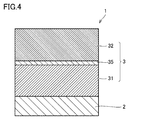
- FIG. 4 is a schematic enlarged cross-sectional view of a cutting tool according to another embodiment of the present disclosure.
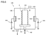
- FIG. 5 is a schematic sectional view of the magnetron sputtering apparatus used in the examples.
- FIG. 6 is a schematic plan view of the magnetron sputtering apparatus shown in FIG.
- titanium alloys which are often used in the medical and aircraft industries, are called difficult-to-cut materials and have the following features. (1) High temperature strength results in high cutting temperature, and (2) low thermal conductivity causes heat to accumulate at the cutting edge and is chemically active, which facilitates adhesion wear. When such a titanium alloy is cut, the life of the cutting tool may be shortened due to heat generated by the cutting, or chatter vibration may occur during the cutting, resulting in deterioration of the working accuracy.
- a cutting tool comprising a base material and a coating formed on the base material,
- the coating film includes a first layer formed on the base material and a second layer formed on the first layer,
- the first layer is made of a boride containing zirconium as a constituent element
- the second layer is made of a nitride containing zirconium as a constituent element.
- the above cutting tool can achieve a long life when processing a work material containing titanium.
- the thickness of the first layer is 0.5 ⁇ m or more and 10 ⁇ m or less. According to this, the above cutting tool can achieve a longer life in processing a work material containing titanium.
- the thickness of the second layer is 0.5 ⁇ m or more and 10 ⁇ m or less. According to this, the above cutting tool can achieve a longer life in processing a work material containing titanium.
- the boride contains ZrB 2 . According to this, since the film hardness is high and the thermal conductivity is high, the thermal permeability of the cutting tool as a whole is further improved, so that the cutting heat is applied to the base material (when the cutting tool is a cutting tool, It can be released to a fixed holder), and in particular, wear resistance of the cutting tool during continuous cutting is improved.
- the nitride contains ZrN. According to this, the adhesion to the work material is reduced, and in particular, the wear resistance of the cutting tool during continuous cutting is improved.
- the boride further contains titanium as a constituent element. This allows the coating to have a high hardness.
- the boride further contains silicon as a constituent element, When the total number of metal atoms constituting the boride is 1, the atomic ratio of silicon is more than 0 and 0.2 or less. This allows the coating to have a high hardness.
- the nitride further contains silicon as a constituent element, When the total number of metal atoms constituting the nitride is 1, the atomic ratio of silicon is more than 0 and 0.2 or less. This allows the coating to have a high hardness.
- the boride further contains vanadium as a constituent element, When the total number of metal atoms constituting the boride is 1, the atomic ratio of vanadium is more than 0 and 0.2 or less. When vanadium is contained in the boride, a low-melting point oxide is generated and lubricity is improved, so that the friction and wear characteristics of the boride are improved.
- the nitride further contains vanadium as a constituent element,
- the atomic ratio of vanadium is more than 0 and 0.2 or less. According to this, the coating can have high lubricity on the surface.
- the coating further includes a surface layer formed on the second layer,
- the surface layer is made of carbonitride containing zirconium as a constituent element. According to this, the cutting tool has improved anti-adhesion performance and can achieve a longer life.
- the coating further includes a base layer formed between the base material and the first layer,
- the underlayer is made of a metal or compound containing at least one element selected from the group consisting of titanium and chromium as a constituent element. According to this, the cutting tool has excellent adhesion.
- a method of manufacturing a cutting tool according to an aspect of the present disclosure is the method of manufacturing a cutting tool according to any one of (1) to (12) above, A step of preparing the base material, Forming the first layer on the substrate using a physical vapor deposition method; Forming the second layer on the first layer using a physical vapor deposition method; including.
- a film formed using a physical vapor deposition method has high crystallinity and can have excellent wear resistance. Therefore, the obtained cutting tool can achieve a long life.
- this embodiment is not limited to this.
- the same reference numerals represent the same or corresponding parts.
- the notation in the form of "AB” means the upper and lower limits of the range (that is, A or more and B or less), and when A has no unit, B only has a unit. The unit of B and the unit of B are the same.
- the chemical formula when a compound is represented by a chemical formula in which the composition ratio of constituent elements is not limited, such as “ZrN”, the chemical formula is represented by any conventionally known composition ratio (element ratio). Shall be included.
- the above chemical formula includes not only the stoichiometric composition but also the non-stoichiometric composition.
- the chemical formula “ZrN” includes not only the stoichiometric composition “Zr 1 N 1 ”, but also a non-stoichiometric composition such as “Zr 1 N 0.8 ”. This also applies to the description of compounds other than "ZrN".
- the surface-coated cutting tool according to the present embodiment (hereinafter sometimes simply referred to as “cutting tool”) is A cutting tool comprising a base material and a coating formed on the base material,
- the coating film includes a first layer formed on the base material and a second layer formed on the first layer,
- the first layer is made of a boride containing zirconium as a constituent element
- the second layer is made of a nitride containing zirconium as a constituent element.
- the above cutting tool can achieve a long life when processing a work material containing titanium.
- the “working material containing titanium” means a working material made of metallic titanium or a working material made of an alloy containing titanium as a constituent element. Examples of the alloy containing titanium include Ti6AL-4V alloy.
- the cutting tool according to the present embodiment includes, in a coating, a first layer made of a boride containing zirconium as a constituent element and a second layer made of a nitride containing zirconium as a constituent element. Since the first layer has high thermal conductivity, the heat permeability of the cutting tool as a whole is improved, and the cutting heat generated during cutting can be released to the base material. Therefore, in particular, the wear resistance of the cutting tool during continuous cutting is improved and the life is extended.
- the coating film when a coating film is formed on a base material of a cutting tool, the coating film has a higher hardness than the base material. Therefore, of the layers constituting the coating film, the layers closer to the hardness of the base material are laminated in order. Then, a layer having high hardness was formed on the surface side.
- the present inventors focused on the high thermal conductivity of “borides containing zirconium as a constituent element”, and in order to quickly release the cutting heat accumulated in the coating to the base material side, the boride was first For the first time, the inventors have found a configuration in which a "nitride containing zirconium as a constituent element" having a hardness lower than that of the boride is formed on the first layer as a layer.
- the first layer tends to have high compressive residual stress, high hardness, and low toughness.
- the second layer tends to have lower stress, lower hardness, and higher toughness than the first layer. Since the first layer and the second layer have different properties as described above, the property of the first layer having low toughness is complemented by the second layer having high toughness, and the compressive residual stress of the second layer. The property of being small is complemented by the first layer having a large compressive residual stress. Therefore, it is considered that the toughness, hardness, and compressive residual stress are improved in a good balance in the entire coating, and the life of the cutting tool is extended in processing a work material containing titanium.
- the cutting tool is a cutting tool suitable for processing a work material containing titanium, it can also be used for processing other conventionally known materials such as iron, steel, cast iron, and stainless steel.
- FIG. 1 is a schematic enlarged cross-sectional view of a cutting tool according to an embodiment of the present disclosure.
- a cutting tool 1 includes a base material 2 and a coating film 3 formed on the base material 2.
- the coating film 3 preferably covers the entire surface of the base material 2, but even if a part of the base material 2 is not covered with the coating film 3 or the structure of the coating film 3 is partially different, It does not deviate from the range.
- the cutting tool of the present embodiment includes a drill, an end mill, a cutting edge exchangeable cutting tip for a drill, a cutting edge exchangeable cutting tip for an end mill, a cutting edge exchangeable cutting tip for milling, a cutting edge exchangeable cutting tip for turning, a metal saw, and a gear cutting. It can be suitably used as a cutting tool such as a tool, a reamer, and a tap.
- any base material conventionally known as this type of base material can be used.
- cemented carbide for example, tungsten carbide (WC) -based cemented carbide, cemented carbide containing Co in addition to WC, cemented carbide containing carbonitrides such as Ti, Ta, and Nb in addition to WC).
- Cermet having TiC, TiN, TiCN, etc.
- high speed steel high speed steel, ceramics (titanium carbide, silicon carbide, silicon nitride, aluminum nitride, aluminum oxide, etc.), cubic boron nitride sintered body (cBN) It is preferably any one selected from the group consisting of a sintered body) and a diamond sintered body.
- ceramics titanium carbide, silicon carbide, silicon nitride, aluminum nitride, aluminum oxide, etc.
- cBN cubic boron nitride sintered body It is preferably any one selected from the group consisting of a sintered body) and a diamond sintered body.
- WC-based cemented carbide and cermet particularly TiCN-based cermet. Since these base materials have an excellent balance between hardness and strength, especially at high temperatures, when used as a base material for a cutting tool, they can contribute to prolonging the life of the cutting tool.
- the coating 3 included in the cutting tool 1 of the present embodiment includes a first layer 31 formed on the base material 2 and a second layer 32 formed on the first layer 31 (FIG. 1). .
- the coating 3 may include other layers in addition to the first layer 31 and the second layer 32. Examples of the other layer include a surface layer 33 (FIG. 2) formed on the second layer 32, and a base layer 34 (formed between the base material 2 and the first layer 31). 3), an intermediate layer 35 (FIG. 4) formed between the first layer 31 and the second layer 32, and the like.
- the surface layer 33, the base layer 34, and the intermediate layer 35 will be described later.
- the coating 3 has the function of improving various characteristics such as wear resistance and fracture resistance of the cutting tool and prolonging the life of the cutting tool.
- the coating film has a total thickness of 1 ⁇ m or more and 15 ⁇ m or less. If the total thickness of the coating is less than 1 ⁇ m, the coating may be too thin to achieve the desired effect. On the other hand, if the total thickness of the coating exceeds 15 ⁇ m, the coating tends to chip at the initial stage of cutting and the life of the cutting tool tends to be shortened.
- the total thickness of the coating can be measured by observing the cross section of the coating with a SEM (scanning electron microscope).
- the observation magnification of the cross-section sample is set to 5000 to 10000 times, the observation area is set to 100 to 500 ⁇ m 2 , and the thickness at three locations in one visual field is measured, and the average value thereof is defined as “thickness”. The same applies to the thickness of each layer described below unless otherwise specified.
- the absolute value of the compressive residual stress of the coating is preferably 6 GPa or less.
- the compressive residual stress of the coating is a type of internal stress (intrinsic strain) existing in the entire coating and is represented by a numerical value of “ ⁇ ” (minus) (unit: “GPa” is used in this embodiment). Refers to stress. Therefore, the concept of “large compressive residual stress” indicates that the absolute value of the numerical value becomes large. Further, the concept of "small compressive residual stress” means that the absolute value of the numerical value becomes small. That is, "the absolute value of the compressive residual stress is 6 GPa or less” means that the residual stress of the coating film is -6 GPa or more and less than 0 GPa.
- the residual stress of the coating exceeds 0 GPa, it becomes tensile residual stress, and it tends to be difficult to suppress the development of cracks generated from the outermost surface of the coating.
- the absolute value of the compressive residual stress exceeds 6 GPa, the compressive residual stress is too large, and the coating tends to peel off from the edge portion of the cutting tool before the start of cutting, and the life of the cutting tool tends to be shortened.
- the compressive residual stress is measured by the 2 ⁇ -sin 2 ⁇ method using an X-ray residual stress device (see pages 54 to 66 of “X-ray stress measurement method” (Japan Society of Materials, 1981, Yokendo Co., Ltd.)). can do.
- the hardness of the film is preferably 29 GPa or more and 60 GPa or less, and more preferably 40 GPa or more and 60 GPa or less. According to this, the coating has sufficient hardness.
- the hardness of the entire coating can be measured by a method using a nano indenter (for example, Nano Indenter XP manufactured by MTS). Specifically, the hardness of three points on the surface of the coating film is measured, and the average value thereof is defined as "hardness".
- the first layer is formed on the base material.
- the first layer may be formed in direct contact with the surface of the base material, or may be formed on the base material via a base layer described later.
- the first layer is made of a boride containing Zr (zirconium) as a constituent element. According to this, the first layer has high film hardness and high thermal conductivity. Therefore, the heat permeability of the cutting tool as a whole is improved, and the cutting heat can be released to the base material. In particular, in machining a difficult-to-cut material whose cutting edge temperature becomes high during machining, the wear resistance of the cutting tool is improved and a long life can be achieved.
- Examples of the boride include ZrB 2 , ZrB, ZrSiB 2 , and ZrVB 2 .
- the boride preferably contains ZrB 2 .
- the boride may be used alone or in combination of two or more.
- composition of the first layer and the atomic number ratio of each atom (Zr, and Si and V described later) to the total number of metal atoms in the first layer were determined by using an X-ray photoelectron spectroscopy analyzer (XPS). Can be measured. Specifically, by irradiating the sample surface with X-rays and measuring the kinetic energy of photoelectrons emitted from the sample surface, the composition and chemical bond state of the elements constituting the sample surface are analyzed.
- the composition of each layer including the second layer, the underlayer, the surface layer, and the intermediate layer, which will be described later, and the atomic ratio of each atom (Ti, Cr, Zr, Si, V) to the total number of metal atoms in each layer are also the same. , X-ray photoelectron spectroscopy analyzer (XPS).
- metal atom means hydrogen, helium, neon, argon, krypton, xenon, radon, fluorine, chlorine, bromine, iodine, astatine, oxygen, sulfur, selenium, tellurium, nitrogen, phosphorus, arsenic, Refers to atoms of elements other than antimony, carbon, and boron.
- the boride is preferably hexagonal.
- the c-axis of the crystal is perpendicular to the main surface of the base material, and the strength tends to increase and the abrasion resistance tends to improve.
- the crystal structure in the first layer can be analyzed by an X-ray diffractometer known in the art.
- the boride preferably contains Ti (titanium) as a constituent element.
- Ti titanium
- the atomic ratio of Ti is preferably more than 0 and 0.5 or less.
- the boride include Zr 1-x Ti x B 2 (where x is more than 0 and 0.5 or less).
- the boride may include Si (silicon) as a constituent element. That is, the boride further contains silicon as a constituent element, and when the total number of metal atoms constituting the boride is 1, the atomic ratio of silicon is more than 0 and not more than 0.2. preferable.
- Examples of the boride include Zr 1-y Si y B 2 (where y is more than 0 and 0.2 or less).
- the first layer becomes brittle and wear tends to be accelerated. Further, when an alloy target serving as a metal raw material of the boride is produced by hot isostatic pressing, the alloy target is cracked during firing, and a material strength usable for forming the first layer is obtained. Tends to be difficult.
- the atomic ratio of silicon is 0.01 or more when the total number of metal atoms constituting the boride is 1. It is more preferably 0.15 or less, further preferably 0.05 or more and 0.15 or less.
- the boride can contain V (vanadium) as a constituent element. That is, the boride further contains vanadium as a constituent element, and when the total number of metal atoms constituting the boride is 1, the atomic ratio of vanadium is more than 0 and not more than 0.2. preferable.
- the boride include Zr 1-z V z B 2 (where z is more than 0 and 0.2 or less). In this case, even if the surface of the first layer is oxidized in the high temperature environment during cutting, the oxide of vanadium has a low melting point and thus acts as a lubricant during cutting, and can suppress the adhesion of the work material.
- the atomic ratio of vanadium exceeds 0.2, the hardness of the first layer tends to decrease.
- the atomic ratio of vanadium is more than 0 and not more than 0.15 when the total number of metal atoms constituting the boride is 1. It is preferably 0.05 or more and 0.15 or less.
- the first layer may contain inevitable impurities other than Zr, B, Ti, Si and V. That is, "the first layer is made of a boride containing zirconium as a constituent element" does not only mean that the first layer is made of a boride containing zirconium as a constituent element, as long as the effects of the present disclosure are exhibited.
- the first layer is a concept including a boride containing zirconium as a constituent element and a case where unavoidable impurities are mixed therein. Inevitable impurities include, for example, oxygen and carbon.
- the content ratio of the total unavoidable impurities in the first layer is preferably more than 0 atom% and less than 1 atom%.
- atomic% means the ratio (%) of the number of atoms to the total number of atoms constituting the first layer.
- the ratio (%) of the number of atoms to the total number of atoms forming the first layer can be measured using the XPS analysis described above.
- the thickness of the first layer is preferably 0.5 ⁇ m or more and 10 ⁇ m or less, and more preferably 0.5 ⁇ m or more and 4 ⁇ m or less.
- the thickness of the first layer can be measured by observing the cross section of the coating with a SEM (scanning electron microscope).
- the second layer is formed on the first layer.
- the second layer may be formed in direct contact with the surface of the first layer, or may be formed on the first layer via an intermediate layer described later.
- the second layer is made of a nitride containing Zr (zirconium) as a constituent element. Since the second layer contains zirconium as a constituent element, the second layer has an excellent balance of wear resistance, oxidation resistance and toughness. Further, when Cr (chrome) and Ti are not contained in the second layer, the damage of the coating does not proceed due to the diffusion of the element of the work material. Therefore, the cutting tool including the second layer can achieve a long life.
- nitride examples include ZrN, ZrSiN, ZrVN and the like.
- the nitride preferably contains ZrN.
- the above nitrides may be used alone or in combination of two or more.
- the above-mentioned nitride is preferably cubic type.
- the crystal structure of the nitride is cubic and has (111) orientation, which is the dense surface of the crystal, the strength is increased and the wear resistance is improved.
- the crystal structure in the second layer can be analyzed by an X-ray diffractometer known in the art.
- the nitride can contain Si (silicon) as a constituent element. That is, the nitride further contains silicon as a constituent element, and when the total number of metal atoms constituting the nitride is 1, the atomic ratio of silicon is more than 0 and not more than 0.2. preferable. Examples of the nitride include Zr 1-v Si v N (where v is more than 0 and 0.2 or less).
- the second layer becomes brittle and wear tends to be accelerated. Further, when an alloy target serving as a metal raw material of the above-mentioned nitride is produced by hot isostatic pressing, the alloy target is cracked during firing, and a material strength usable for forming the second layer is obtained. Tends to be difficult.
- the atomic ratio of silicon is 0.01 when the total number of metal atoms constituting the nitride is 1. It is more preferably not less than 0.15 and is more preferably not less than 0.05 and not more than 0.15.
- the nitride can contain V (vanadium) as a constituent element. That is, the nitride further contains vanadium as a constituent element, and when the total number of metal atoms constituting the nitride is 1, the atomic ratio of vanadium is more than 0 and not more than 0.2. preferable.
- the nitride include Zr 1-w V w N (where w is more than 0 and 0.2 or less). In this case, even if the surface of the second layer is oxidized in the high temperature environment during cutting, the oxide of V has a low melting point and thus acts as a lubricant during cutting and can suppress the adhesion of the work material.
- the atomic ratio of vanadium exceeds 0.2, the hardness of the second layer tends to decrease.
- the atomic ratio of vanadium is 0 when the total number of metal atoms constituting the nitride is 1. It is more preferably more than 0.15 and is more preferably 0.05 or more and 0.15 or less.
- the second layer can contain inevitable impurities other than Zr, Si, V and N. That is, "the second layer is made of a nitride containing zirconium as a constituent element” does not only mean that the second layer is made of a nitride containing zirconium as a constituent element, but also as long as the effect of the present disclosure is exhibited. This is a concept including a nitride in which the second layer contains zirconium as a constituent element and a case where unavoidable impurities are mixed therein. Inevitable impurities include, for example, oxygen and carbon.
- the content ratio of the total unavoidable impurities in the second layer is preferably more than 0 atom% and less than 1 atom%. The ratio (%) of the number of atoms to the total number of atoms forming the second layer can be measured using the XPS analysis described above.
- the thickness of the second layer is preferably 0.5 ⁇ m or more and 10 ⁇ m or less, and more preferably 0.5 ⁇ m or more and 4 ⁇ m or less.
- the thickness of the second layer can be measured by observing the cross section of the coating with a SEM (scanning electron microscope).
- the total thickness of the first layer and the second layer is preferably 1 ⁇ m or more and 20 ⁇ m or less, more preferably 1 ⁇ m or more and 15 ⁇ m or less, and further preferably 2 ⁇ m or more and 7 ⁇ m or less. If the thickness is less than 1 ⁇ m, abrasion resistance tends to be insufficient in continuous machining, and if it exceeds 20 ⁇ m, chipping resistance tends to be unstable in intermittent cutting.
- the coating 3 included in the cutting tool 1 of the present embodiment may include other layers in addition to the first layer 31 and the second layer 32.
- Other layers include, for example, a surface layer 33 (FIG. 2) formed on the second layer 32, and a base layer 34 (FIG. 2) formed between the base material 2 and the first layer 31. 3) and the intermediate layer 35 (FIG. 4) formed between the first layer 31 and the second layer 32.
- the surface layer 33 is formed on the second layer 32 (FIG. 2).
- the surface layer 33 may be a single layer or a multilayer.
- the surface layer 33 is preferably made of carbonitride containing zirconium as a constituent element. Examples of the carbonitride include ZrCN, ZrSiCN, ZrVCN and the like.
- the carbonitrides may be used alone or in combination of two or more.
- carbonitrides tend to have a lower coefficient of friction for work materials than nitrides. It is considered that such a decrease in the coefficient of friction is due to the contribution of carbon atoms.
- the coating includes the surface layer, the coefficient of friction of the coating with respect to the work material decreases, and the cutting tool has a long life.
- a predetermined color can be imparted to the surface layer by adjusting the composition ratio of N and C. Thereby, the appearance of the cutting tool can be provided with designability and distinctiveness, which is industrially useful.
- the above carbonitride preferably further contains silicon as a constituent element.
- the ratio of the number of silicon atoms is preferably more than 0 and 0.2 or less, and 0.05 or more and 0.15 or less. Is more preferable. According to this, the hardness of the surface layer is increased, and the oxidation resistance is improved.
- the above carbonitride preferably further contains vanadium as a constituent element.
- the ratio of the number of vanadium atoms when the total number of metal atoms constituting the carbonitride is 1 is preferably more than 0 and 0.2 or less, and more than 0 and 0.15 or less. Is more preferable. According to this, the adhesion resistance of the surface layer is improved.
- the above carbonitride preferably further contains B (boron) as a constituent element.
- B boron
- the ratio of the number of boron atoms is preferably more than 0 and 0.5 or less, and 0 And more preferably 0.2 or less. According to this, the film hardness is improved.
- the thickness of the surface layer is preferably 0.1 ⁇ m or more. If the thickness of the surface layer is less than 0.1 ⁇ m, the effect of imparting lubricity by the surface layer tends to be difficult to obtain. On the other hand, the upper limit of the thickness of the surface layer is not particularly limited, but even if it exceeds 2 ⁇ m, the effect of imparting the above-mentioned lubricity tends to remain unchanged. Therefore, in consideration of cost, the thickness of the surface layer is preferably 2 ⁇ m or less. The thickness of the surface layer can be measured by observing the cross section of the coating with a SEM (scanning electron microscope).
- the base layer 34 is formed between the base material 2 and the first layer 31 (FIG. 3).
- the base layer 34 may be a single layer or a multilayer.
- the underlayer 34 is preferably made of a metal or a compound containing at least one element selected from the group consisting of Ti (titanium) and Cr (chromium) as a constituent element.
- the metal include titanium metal, chromium metal, and alloys containing titanium and chromium as constituent elements.
- the compound include CrN and TiN.
- the thickness of the underlayer is preferably 2 nm or more and 0.5 ⁇ m or less, more preferably 2 nm or more and 0.1 ⁇ m or less.
- the thickness of the underlayer can be measured by observing the cross section of the coating with a SEM (scanning electron microscope) or a TEM (transmission electron microscope).
- a method for manufacturing a cutting tool according to an embodiment of the present disclosure described above is a method for manufacturing the cutting tool, A step of preparing the base material (hereinafter, sometimes referred to as “first step”); A step of forming the first layer on the base material by using a physical vapor deposition method (hereinafter, sometimes referred to as “second step”); A step of forming the second layer on the first layer using a physical vapor deposition method (hereinafter, sometimes referred to as “third step”); including.
- the physical vapor deposition method is a vapor deposition method in which a raw material (also referred to as an evaporation source or a target) is vaporized by utilizing a physical action and the vaporized raw material is attached onto a substrate.
- the physical vapor deposition method used in this embodiment is preferably at least one selected from the group consisting of a cathode arc ion plating method, a balanced magnetron sputtering method and an unbalanced magnetron sputtering method.
- the surface of the base material can be subjected to a metal ion bombardment cleaning treatment before forming the coating film, so that the cleaning time can be shortened.
- a base material is installed in the apparatus and a target is installed as a cathode, and then a high current is applied to the target to cause arc discharge.
- the atoms forming the target are evaporated and ionized, and the atoms are deposited on the substrate to which the negative bias voltage is applied to form a film.
- a base material is installed in the apparatus and a target is installed on a magnetron electrode equipped with a magnet that forms a balanced magnetic field, and high frequency power is applied between the magnetron electrode and the base material. Is applied to generate gas plasma. A film is formed by causing the ions of the gas generated by the generation of this gas plasma to collide with the target to ionize the atoms emitted from the target and deposit them on the substrate.
- the unbalanced magnetron sputtering method forms a film by making the magnetic field generated by the magnetron electrodes in the above balanced magnetron sputtering method non-equilibrium.
- the base material is prepared.
- a cemented carbide base material is prepared as the base material.
- the cemented carbide base material may be a commercially available product or may be manufactured by a general powder metallurgy method.
- a WC powder and a Co powder are mixed by a ball mill or the like to obtain a mixed powder.
- the mixed powder is dried, it is molded into a predetermined shape to obtain a molded body. Further, by sintering the formed body, a WC—Co based cemented carbide (sintered body) is obtained.
- the sintered body is subjected to predetermined cutting edge processing such as honing treatment to manufacture a base material made of a WC-Co based cemented carbide.
- predetermined cutting edge processing such as honing treatment to manufacture a base material made of a WC-Co based cemented carbide.
- a step of cleaning the base material can be performed before the second step described below.
- the surface of the base material can be subjected to ion bombardment treatment.
- the soft binder phase can be removed from the surface of the base material.
- the underlying layer can be formed by the ion bombardment treatment itself. That is, by using a target containing an element of chromium, titanium or a combination thereof in the ion bombardment treatment, these elements can be attached to the surface of the base material as an underlayer while cleaning the surface of the base material. . Then, by performing a step of forming a first layer, which is a second step described later, on the surface to which these elements adhere, an underlayer having excellent adhesion can be formed together with the first layer. .
- the element used for the ion bombardment treatment and contained in the underlayer is more preferably chromium. Since chromium is a sublimable element, the generation of molten particles (droplets) during the ion bombardment treatment is small, and the surface roughness of the substrate can be prevented.
- the first step and the subsequent steps of cleaning the base material can be performed as follows. First, a chip having an arbitrary shape is prepared as the base material 2 (first step). Next, the substrate 2 is mounted in the chamber 130 of the film forming apparatus 120. For example, to explain using the film forming apparatus 120 shown in FIG. 5, the base material 2 is attached to the outer surface of the base material holder 122 on the rotary table 121 rotatably provided in the center of the chamber 130. A bias power source 142 is attached to the base material holder 122.
- an evaporation source 131 for forming a first layer and an evaporation source 132 for forming a second layer, which correspond to an alloy target which is a metal raw material of the coating, are provided at predetermined positions in the chamber 130. It is attached to an evaporation source 133 for ion bombardment and an evaporation source 134 for forming a surface layer, respectively.
- a pulse power supply 141 is attached to the evaporation source 131 for forming the first layer and the evaporation source 132 for forming the second layer, and a pulse power source (evaporation source 133 for ion bombardment) and an evaporation source 134 for forming the surface layer are also provided ( (Not shown).
- a gas introduction port 123 for introducing an atmospheric gas is provided in the chamber 130, and a gas exhaust port 124 for exhausting the atmospheric gas from the chamber 130 is provided.
- the ambient gas in the chamber 130 can be sucked from the gas outlet 124 by a vacuum pump.
- argon gas is introduced as an atmospheric gas (sputtering gas) from the gas introduction port 123, the pressure in the chamber 130 is maintained at 1.0 to 4.0 Pa, and the voltage of the bias power source 142 is gradually increased to ⁇ 1000.
- the surface of the base material 2 is cleaned for 15 to 90 minutes at an ionization voltage of ⁇ 400 V (ion bombardment treatment with argon ions). Thereby, when the base material 2 is a cemented carbide base material, the binder phase can be removed from the surface.
- the first layer is formed on the base material.
- various methods are used depending on the composition of the first layer to be formed. For example, zirconium, boron, titanium, silicon, vanadium, and the like, the method of using an alloy target in which the particle diameters are changed, the method of using a plurality of targets having different compositions, the bias voltage applied during film formation is a pulse voltage Method, a method of changing the gas flow rate during film formation, a method of adjusting the rotation speed of the substrate holder that holds the substrate in the film forming apparatus, and the like.
- the first layer can be formed by combining these methods.
- the second step can be performed as follows. That is, following the cleaning of the base material 2, Ar is introduced as an atmospheric gas while the base material 2 is rotated in the center of the chamber 130. Further, the evaporation source for forming the first layer is maintained while maintaining the temperature of the base material 2 at 400 to 700 ° C., the gas pressure at 0.3 to 0.5 Pa, and the voltage of the bias power source 142 within the range of ⁇ 30 to ⁇ 100V.
- a pulse power supply 141 is used for 131 to supply electric power of 5.5 to 7.5 kW.
- the second layer is formed on the first layer.
- various methods are used depending on the composition of the second layer to be formed.
- zirconium a method of using an alloy target having different particle diameters such as silicon and vanadium, a method of using a plurality of targets having different compositions, a method of using a bias voltage applied during film formation as a pulse voltage, A method of changing the gas flow rate, a method of adjusting the rotation speed of the substrate holder that holds the substrate in the film forming apparatus, and the like can be mentioned.
- the second layer can be formed by combining these methods.
- the third step can be performed as follows. That is, following the step of forming the first layer, argon gas is introduced as a sputtering gas and nitrogen gas is introduced as a reaction gas in a state where the substrate 2 on which the first layer is formed is rotated in the center of the chamber 130. . Further, with the substrate 2 kept at a temperature of 400 to 700 ° C., the reaction gas pressure of 0.3 to 1 Pa, and the voltage of the bias power source 142 in the range of ⁇ 30 to ⁇ 100 V, evaporation for forming the second layer. By supplying 5.5 to 7.5 kW of electric power from the pulse power source 141 to the source 132, metal ions are generated from the evaporation source 132. After that, when a predetermined time has elapsed, the power supply from the pulse power supply 141 is stopped, and the second layer is formed on the first layer. Furthermore, the thickness of the second layer is adjusted within a predetermined range by adjusting the film formation time.
- a step of forming a surface layer can be performed after the third step.
- the step of forming the surface layer is performed as follows. That is, subsequently to the step of forming the second layer, argon gas is introduced as a sputtering gas and nitrogen gas is introduced as a reaction gas in a state in which the base material 2 on which the second layer is formed is rotated in the center of the chamber 130. . Further, while maintaining the substrate 2 at a temperature of 400 to 700 ° C., a reaction gas pressure of 0.3 to 1 Pa, and a bias power supply 142 voltage of ⁇ 30 to ⁇ 100 V, a surface layer is formed.
- a pulsed power supply supplies 5.5 to 7.5 kW of power to the evaporation source 134.
- metal ions are generated from the evaporation source 134, and when a predetermined time has elapsed, the supply of power from the pulse power supply is stopped and a surface layer is formed on the second layer.
- the evaporation layer 132 for forming the second layer may be used instead of the evaporation source 134 for forming the surface layer to form the surface layer.
- compressive residual stress may be applied to the coating. This is because the toughness is improved.
- the compressive residual stress can be applied by, for example, a blast method, a brush method, a barrel method, an ion implantation method, or the like.
- a surface coating cutting tool comprising a substrate and a coating formed on the substrate,
- the coating film includes a first layer formed on the base material and a second layer formed on the first layer,
- the first layer is made of a boride containing Zr as a constituent element
- the second layer is a surface-coated cutting tool, which is made of a nitride containing Zr as a constituent element.
- Appendix 2 The surface-coated cutting tool according to Appendix 1, wherein the first layer has a thickness of 0.5 ⁇ m or more and 10 ⁇ m or less.
- the nitride further contains Si as a constituent element, 8.
- the boride further contains V as a constituent element, 9.
- the nitride further contains V as a constituent element, 10.
- the coating further includes a surface layer formed on the second layer, 11.
- the coating further includes a base layer formed between the base material and the first layer, 12.
- Appendix 13 The method for producing a surface-coated cutting tool according to any one of appendices 1 to 12, Preparing the substrate, Forming the first layer on the substrate using a physical vapor deposition method; Forming the second layer on the first layer using a physical vapor deposition method; A method for producing a surface-coated cutting tool, comprising:
- the thickness of each of the coating film, the first layer, the second layer, and the surface layer described later is a value obtained by the following method. That is, the cross section obtained by cutting the manufactured cutting tool is observed by using the SEM (scanning electron microscope) according to the procedure described above, and the value obtained by averaging the thickness measured in each cross section is used. is there.
- FIG. 5 is a schematic cross-sectional view of the film forming apparatus (magnetron sputtering apparatus) used in this example.
- FIG. 6 is a schematic plan view of the film forming apparatus used in this example.
- First step step of preparing a base material
- the base material 2 a grade of cemented carbide of JIS standard P30, a shape of which is CNMG120408 of JIS standard and SEMT13T3AGSN manufactured by Sumitomo Electric Hard Metal Co., Ltd., and a radius end mill ( ⁇ 12 mm), respectively. It prepared (process which prepares a base material).
- the base material 2 was attached to the outer surface of the base material holder 122 on the rotary table 121 rotatably provided in the center of the chamber 130 of the film forming apparatus 120.
- an evaporation source for forming a first layer which is an alloy target serving as a metal raw material for the coating (an alloy evaporation source including a metal raw material having a composition forming the first layer) 131.
- An evaporation source for forming a second layer (an evaporation source made of an alloy of a metal raw material having a composition forming the second layer) 132, and an evaporation source for forming a surface layer (an alloy made of a metal raw material having a composition of a surface layer) Evaporation source) 134 was attached.
- a pulse power source 141 was attached to the evaporation source 131 for forming the first layer and the evaporation source 132 for forming the second layer. Further, a pulse power source (not shown) was also attached to the evaporation source 133 for ion bombardment and the evaporation source 134 for forming the surface layer.
- a bias power source 142 was attached to the base material holder 122.
- a gas introduction port 123 for introducing an atmospheric gas is provided in the chamber 130, and a gas exhaust port 124 for exhausting the atmospheric gas from the chamber 130 is provided. Therefore, a vacuum pump is provided from the gas exhaust port 124. Thus, the atmospheric gas in the chamber 130 can be sucked and exhausted.
- the inside of the chamber 130 was decompressed by the vacuum pump, and the base 2 of the base holder 122 was rotated by rotating the rotary table 121. Then, the surface temperature of the base material 2 is heated to 600 ° C. by a heater (not shown) installed in the apparatus 120, and a vacuum is evacuated until the pressure in the chamber 130 reaches 1.0 ⁇ 10 ⁇ 4 Pa. I did.
- argon gas is introduced as a sputtering gas from the gas introduction port 123, the pressure in the chamber 130 is maintained at 3.0 Pa, the voltage of the bias power source 142 is gradually increased to ⁇ 1000 V, and the surface of the substrate 2 is exposed.
- a treatment for removing the binder phase from the surface of the base material 2 ion bombardment treatment with argon ions was performed.
- argon gas was exhausted from the inside of the chamber 130 (step of cleaning the base material).
- Comparative Example 1 and Comparative Example 5 a ZrN layer (a layer made of a compound represented by ZrN, the same applies hereinafter) was prepared as a layer corresponding to the first layer.
- a ZrN layer (a layer made of a compound represented by ZrN, the same applies hereinafter) was prepared as a layer corresponding to the first layer.
- Comparative Example 3 and Comparative Example 4 an AlTiN layer and an AlCrN layer having the compositions shown in Table 1 were produced as layers corresponding to the first layer.
- Comparative Examples 1 to 4 are examples in which the second layer is not formed, as will be described later. Thereby, the 2nd process was implemented.
- Comparative Examples 1 to 4 the second layer was not formed.
- Comparative Example 5 a ZrB 2 layer was formed as the second layer.
- a surface layer having the composition and thickness shown in Table 2 was formed subsequent to the step of forming the second layer.
- the substrate 2 having the second layer formed thereon was rotated in the center of the chamber 130, and Ar was introduced as an atmosphere gas and both nitrogen and methane gas were introduced as reaction gases.
- the reaction gas pressure was 0.4 Pa, and the bias power source 142 voltage was ⁇ 150 V, 6 kW of power was supplied to the surface layer forming evaporation source 134.
- metal ions were generated from the evaporation source 134, power supply was stopped when a predetermined time had elapsed, and a surface layer was formed on the second layer.
- the cutting tools of Examples 1 to 10 and Comparative Examples 1 to 5 were manufactured as described above.
- the thickness of the entire coating in Table 2 includes the thickness of the surface layer.
- composition of the first layer and the second layer in Table 1 and the “composition” of the surface layer in Table 2 are measured using XPS (X-ray photoelectron spectroscopy analyzer).
- the “hardness” of the entire coating in Table 2 is the value confirmed by a nano indenter (Nano Indenter XP manufactured by MTS).
- the “compressive residual stress” of the entire coating in Table 2 is the 2 ⁇ -sin 2 ⁇ method using the X-ray residual stress measuring device (“X-ray stress measuring method” (Japan Society for Materials, 1981, issued by Yokendo Co., Ltd.) Pp. 54-66).
- Examples 1 to 10 have a significantly longer tool life in end milling of titanium alloys than Comparative Examples 1 to 5.
- 1 cutting tool 2 base material, 3 coating, 31 1st layer, 32 2nd layer, 33 surface layer, 34 base layer, 35 intermediate layer, 120 film forming apparatus, 121 rotary table, 122 base material holder, 123 gas introduction Mouth, 124 gas outlet, 130 chamber, 131, 132, 133, 134 evaporation source, 141 pulse power supply, 142 bias power supply.
Abstract
L'invention concerne un outil de coupe qui contient un matériau de base, et un film de revêtement formé sur ledit matériau de base. Ledit film de revêtement contient une première couche formée sur ledit matériau de base, et une seconde couche formée sur ladite première couche. Ladite première couche est constituée d'un borure contenant un zirconium en tant qu'élément constitutif, et ladite seconde couche est constituée d'un nitrure contenant un zirconium en tant qu'élément constitutif.
Priority Applications (4)
| Application Number | Priority Date | Filing Date | Title |
|---|---|---|---|
| US16/635,248 US20200406365A1 (en) | 2018-10-10 | 2019-07-10 | Cutting tool and method for manufacturing same |
| CN201980066361.7A CN112805109A (zh) | 2018-10-10 | 2019-07-10 | 切削工具及其制造方法 |
| EP19871201.0A EP3865233A4 (fr) | 2018-10-10 | 2019-07-10 | Outil de coupe, et procédé de fabrication de celui-ci |
| JP2019562668A JP6641610B1 (ja) | 2018-10-10 | 2019-07-10 | 切削工具及びその製造方法 |
Applications Claiming Priority (2)
| Application Number | Priority Date | Filing Date | Title |
|---|---|---|---|
| JP2018191737 | 2018-10-10 | ||
| JP2018-191737 | 2018-10-10 |
Publications (1)
| Publication Number | Publication Date |
|---|---|
| WO2020075356A1 true WO2020075356A1 (fr) | 2020-04-16 |
Family
ID=70164666
Family Applications (1)
| Application Number | Title | Priority Date | Filing Date |
|---|---|---|---|
| PCT/JP2019/027269 WO2020075356A1 (fr) | 2018-10-10 | 2019-07-10 | Outil de coupe, et procédé de fabrication de celui-ci |
Country Status (3)
| Country | Link |
|---|---|
| US (1) | US20200406365A1 (fr) |
| CN (1) | CN112805109A (fr) |
| WO (1) | WO2020075356A1 (fr) |
Cited By (1)
| Publication number | Priority date | Publication date | Assignee | Title |
|---|---|---|---|---|
| US9820433B2 (en) | 2012-12-28 | 2017-11-21 | Positec Power Tools (Suzhou Co., Ltd.) | Auto mowing system |
Citations (9)
| Publication number | Priority date | Publication date | Assignee | Title |
|---|---|---|---|---|
| JPH05222551A (ja) * | 1992-02-07 | 1993-08-31 | Sumitomo Electric Ind Ltd | 被覆サーメット切削工具の製造方法 |
| JPH10176289A (ja) * | 1996-12-10 | 1998-06-30 | Balzers Ag | 被覆硬質合金 |
| US6492011B1 (en) * | 1998-09-02 | 2002-12-10 | Unaxis Trading Ag | Wear-resistant workpiece and method for producing same |
| JP2003034859A (ja) | 2001-07-23 | 2003-02-07 | Kobe Steel Ltd | 切削工具用硬質皮膜およびその製造方法並びに硬質皮膜形成用ターゲット |
| JP2004042193A (ja) * | 2002-07-11 | 2004-02-12 | Sumitomo Electric Ind Ltd | 被覆切削工具 |
| JP2006001006A (ja) * | 2004-05-17 | 2006-01-05 | Mitsubishi Materials Corp | 高硬度鋼の高速切削加工で硬質被覆層がすぐれた耐摩耗性を発揮する表面被覆超硬合金製切削工具 |
| WO2006070730A1 (fr) | 2004-12-28 | 2006-07-06 | Sumitomo Electric Hardmetal Corp. | Outil de coupe a revetement de surface et son procede de fabrication |
| JP2014014895A (ja) * | 2012-07-09 | 2014-01-30 | Mitsubishi Materials Corp | 表面被覆切削工具 |
| JP2018191737A (ja) | 2017-05-12 | 2018-12-06 | 株式会社ユニバーサルエンターテインメント | 遊技機 |
Family Cites Families (12)
| Publication number | Priority date | Publication date | Assignee | Title |
|---|---|---|---|---|
| US6575671B1 (en) * | 2000-08-11 | 2003-06-10 | Kennametal Inc. | Chromium-containing cemented tungsten carbide body |
| JP3637882B2 (ja) * | 2000-08-31 | 2005-04-13 | 住友電気工業株式会社 | 表面被覆窒化硼素焼結体工具 |
| SE522722C2 (sv) * | 2001-03-28 | 2004-03-02 | Seco Tools Ab | Skärverktyg belagt med titandiborid |
| DE602005023737D1 (de) * | 2004-08-10 | 2010-11-04 | Mitsubishi Shindo Kk | Gussteil aus kupferbasislegierung mit raffinierten kristallkörnern |
| SE529161C2 (sv) * | 2005-06-22 | 2007-05-22 | Seco Tools Ab | Skärverktyg med kompositbeläggning för finbearbetning av härdade stål |
| EP2209929B1 (fr) * | 2007-12-06 | 2013-08-21 | Ceratizit Austria GmbH | Outil revetu |
| JP5488824B2 (ja) * | 2010-08-12 | 2014-05-14 | 三菱マテリアル株式会社 | 硬質難削材の高速切削加工で硬質被覆層がすぐれた耐剥離性とすぐれた耐摩耗性を発揮する表面被覆切削工具 |
| US8440328B2 (en) * | 2011-03-18 | 2013-05-14 | Kennametal Inc. | Coating for improved wear resistance |
| WO2013131943A1 (fr) * | 2012-03-07 | 2013-09-12 | Seco Tools Ab | Corps avec une couche de nitrure à base de métal et procédé pour revêtir le corps |
| CN103409719A (zh) * | 2013-07-08 | 2013-11-27 | 太原理工大学 | 具有复合陶瓷镀层的合金钢纺织剪刀及其制造方法 |
| US9896767B2 (en) * | 2013-08-16 | 2018-02-20 | Kennametal Inc | Low stress hard coatings and applications thereof |
| CN105237020B (zh) * | 2015-08-31 | 2018-08-24 | 中国人民解放军国防科学技术大学 | 一种碳纤维增强ZrB2-ZrN复相陶瓷基复合材料及其制备方法 |
-
2019
- 2019-07-10 WO PCT/JP2019/027269 patent/WO2020075356A1/fr unknown
- 2019-07-10 US US16/635,248 patent/US20200406365A1/en not_active Abandoned
- 2019-07-10 CN CN201980066361.7A patent/CN112805109A/zh active Pending
Patent Citations (9)
| Publication number | Priority date | Publication date | Assignee | Title |
|---|---|---|---|---|
| JPH05222551A (ja) * | 1992-02-07 | 1993-08-31 | Sumitomo Electric Ind Ltd | 被覆サーメット切削工具の製造方法 |
| JPH10176289A (ja) * | 1996-12-10 | 1998-06-30 | Balzers Ag | 被覆硬質合金 |
| US6492011B1 (en) * | 1998-09-02 | 2002-12-10 | Unaxis Trading Ag | Wear-resistant workpiece and method for producing same |
| JP2003034859A (ja) | 2001-07-23 | 2003-02-07 | Kobe Steel Ltd | 切削工具用硬質皮膜およびその製造方法並びに硬質皮膜形成用ターゲット |
| JP2004042193A (ja) * | 2002-07-11 | 2004-02-12 | Sumitomo Electric Ind Ltd | 被覆切削工具 |
| JP2006001006A (ja) * | 2004-05-17 | 2006-01-05 | Mitsubishi Materials Corp | 高硬度鋼の高速切削加工で硬質被覆層がすぐれた耐摩耗性を発揮する表面被覆超硬合金製切削工具 |
| WO2006070730A1 (fr) | 2004-12-28 | 2006-07-06 | Sumitomo Electric Hardmetal Corp. | Outil de coupe a revetement de surface et son procede de fabrication |
| JP2014014895A (ja) * | 2012-07-09 | 2014-01-30 | Mitsubishi Materials Corp | 表面被覆切削工具 |
| JP2018191737A (ja) | 2017-05-12 | 2018-12-06 | 株式会社ユニバーサルエンターテインメント | 遊技機 |
Non-Patent Citations (2)
| Title |
|---|
| See also references of EP3865233A4 |
| YOKENDO: "X-ray stress measuring method", 1981, SOCIETY OF MATERIALS SCIENCE, pages: 54 - 66 |
Cited By (2)
| Publication number | Priority date | Publication date | Assignee | Title |
|---|---|---|---|---|
| US9820433B2 (en) | 2012-12-28 | 2017-11-21 | Positec Power Tools (Suzhou Co., Ltd.) | Auto mowing system |
| US10555456B2 (en) | 2012-12-28 | 2020-02-11 | Positec Power Tools (Suzhou) Co., Ltd. | Auto mowing system |
Also Published As
| Publication number | Publication date |
|---|---|
| CN112805109A (zh) | 2021-05-14 |
| US20200406365A1 (en) | 2020-12-31 |
Similar Documents
| Publication | Publication Date | Title |
|---|---|---|
| JP6222675B2 (ja) | 表面被覆切削工具、およびその製造方法 | |
| WO2012043459A1 (fr) | Outil de coupe | |
| JP6641610B1 (ja) | 切削工具及びその製造方法 | |
| JP3963354B2 (ja) | 被覆切削工具 | |
| JP3914686B2 (ja) | 切削工具とその製造方法 | |
| US10994341B2 (en) | Surface-coated cutting tool and method for manufacturing same | |
| JP7067689B2 (ja) | 表面被覆切削工具及びその製造方法 | |
| JP6984108B2 (ja) | 表面被覆切削工具及びその製造方法 | |
| WO2020075356A1 (fr) | Outil de coupe, et procédé de fabrication de celui-ci | |
| JP6641611B1 (ja) | 切削工具及びその製造方法 | |
| JP7055961B2 (ja) | 表面被覆切削工具及びその製造方法 | |
| WO2020075355A1 (fr) | Outil de coupe, et procédé de fabrication de celui-ci | |
| JP6583763B1 (ja) | 表面被覆切削工具、及びその製造方法 | |
| JP4844879B2 (ja) | 耐熱合金の高速切削加工で硬質被覆層がすぐれた耐摩耗性を発揮する表面被覆切削工具 | |
| JP2019118997A (ja) | 表面被覆切削工具 | |
| JP2019118995A (ja) | 表面被覆切削工具 | |
| JP6743349B2 (ja) | 切削工具 | |
| JP6743350B2 (ja) | 切削工具 | |
| WO2024079889A1 (fr) | Outil de coupe | |
| WO2024062611A1 (fr) | Outil de coupe | |
| WO2022244191A1 (fr) | Outil de coupe | |
| JP2007307652A (ja) | 被覆工具及びその製造方法 | |
| JP5321361B2 (ja) | 表面被覆切削工具 | |
| JP2019118998A (ja) | 表面被覆切削工具 | |
| JP2019098471A (ja) | 表面被覆切削工具 |
Legal Events
| Date | Code | Title | Description |
|---|---|---|---|
| ENP | Entry into the national phase |
Ref document number: 2019562668 Country of ref document: JP Kind code of ref document: A |
|
| 121 | Ep: the epo has been informed by wipo that ep was designated in this application |
Ref document number: 19871201 Country of ref document: EP Kind code of ref document: A1 |
|
| NENP | Non-entry into the national phase |
Ref country code: DE |
|
| ENP | Entry into the national phase |
Ref document number: 2019871201 Country of ref document: EP Effective date: 20210510 |