WO2020071522A1 - 冷延鋼板 - Google Patents
冷延鋼板Info
- Publication number
- WO2020071522A1 WO2020071522A1 PCT/JP2019/039241 JP2019039241W WO2020071522A1 WO 2020071522 A1 WO2020071522 A1 WO 2020071522A1 JP 2019039241 W JP2019039241 W JP 2019039241W WO 2020071522 A1 WO2020071522 A1 WO 2020071522A1
- Authority
- WO
- WIPO (PCT)
- Prior art keywords
- steel sheet
- less
- rolling
- ferrite
- cold
- Prior art date
- Legal status (The legal status is an assumption and is not a legal conclusion. Google has not performed a legal analysis and makes no representation as to the accuracy of the status listed.)
- Ceased
Links
Images




Classifications
-
- C—CHEMISTRY; METALLURGY
- C21—METALLURGY OF IRON
- C21D—MODIFYING THE PHYSICAL STRUCTURE OF FERROUS METALS; GENERAL DEVICES FOR HEAT TREATMENT OF FERROUS OR NON-FERROUS METALS OR ALLOYS; MAKING METAL MALLEABLE, e.g. BY DECARBURISATION OR TEMPERING
- C21D9/00—Heat treatment, e.g. annealing, hardening, quenching or tempering, adapted for particular articles; Furnaces therefor
- C21D9/46—Heat treatment, e.g. annealing, hardening, quenching or tempering, adapted for particular articles; Furnaces therefor for sheet metals
-
- C—CHEMISTRY; METALLURGY
- C21—METALLURGY OF IRON
- C21D—MODIFYING THE PHYSICAL STRUCTURE OF FERROUS METALS; GENERAL DEVICES FOR HEAT TREATMENT OF FERROUS OR NON-FERROUS METALS OR ALLOYS; MAKING METAL MALLEABLE, e.g. BY DECARBURISATION OR TEMPERING
- C21D6/00—Heat treatment of ferrous alloys
- C21D6/001—Heat treatment of ferrous alloys containing Ni
-
- C—CHEMISTRY; METALLURGY
- C21—METALLURGY OF IRON
- C21D—MODIFYING THE PHYSICAL STRUCTURE OF FERROUS METALS; GENERAL DEVICES FOR HEAT TREATMENT OF FERROUS OR NON-FERROUS METALS OR ALLOYS; MAKING METAL MALLEABLE, e.g. BY DECARBURISATION OR TEMPERING
- C21D6/00—Heat treatment of ferrous alloys
- C21D6/002—Heat treatment of ferrous alloys containing Cr
-
- C—CHEMISTRY; METALLURGY
- C21—METALLURGY OF IRON
- C21D—MODIFYING THE PHYSICAL STRUCTURE OF FERROUS METALS; GENERAL DEVICES FOR HEAT TREATMENT OF FERROUS OR NON-FERROUS METALS OR ALLOYS; MAKING METAL MALLEABLE, e.g. BY DECARBURISATION OR TEMPERING
- C21D6/00—Heat treatment of ferrous alloys
- C21D6/005—Heat treatment of ferrous alloys containing Mn
-
- C—CHEMISTRY; METALLURGY
- C21—METALLURGY OF IRON
- C21D—MODIFYING THE PHYSICAL STRUCTURE OF FERROUS METALS; GENERAL DEVICES FOR HEAT TREATMENT OF FERROUS OR NON-FERROUS METALS OR ALLOYS; MAKING METAL MALLEABLE, e.g. BY DECARBURISATION OR TEMPERING
- C21D6/00—Heat treatment of ferrous alloys
- C21D6/008—Heat treatment of ferrous alloys containing Si
-
- C—CHEMISTRY; METALLURGY
- C21—METALLURGY OF IRON
- C21D—MODIFYING THE PHYSICAL STRUCTURE OF FERROUS METALS; GENERAL DEVICES FOR HEAT TREATMENT OF FERROUS OR NON-FERROUS METALS OR ALLOYS; MAKING METAL MALLEABLE, e.g. BY DECARBURISATION OR TEMPERING
- C21D8/00—Modifying the physical properties of ferrous metals or ferrous alloys by deformation combined with, or followed by, heat treatment
- C21D8/02—Modifying the physical properties of ferrous metals or ferrous alloys by deformation combined with, or followed by, heat treatment during manufacturing of plates or strips
-
- C—CHEMISTRY; METALLURGY
- C21—METALLURGY OF IRON
- C21D—MODIFYING THE PHYSICAL STRUCTURE OF FERROUS METALS; GENERAL DEVICES FOR HEAT TREATMENT OF FERROUS OR NON-FERROUS METALS OR ALLOYS; MAKING METAL MALLEABLE, e.g. BY DECARBURISATION OR TEMPERING
- C21D8/00—Modifying the physical properties of ferrous metals or ferrous alloys by deformation combined with, or followed by, heat treatment
- C21D8/02—Modifying the physical properties of ferrous metals or ferrous alloys by deformation combined with, or followed by, heat treatment during manufacturing of plates or strips
- C21D8/0221—Modifying the physical properties of ferrous metals or ferrous alloys by deformation combined with, or followed by, heat treatment during manufacturing of plates or strips characterised by the working steps
- C21D8/0226—Hot rolling
-
- C—CHEMISTRY; METALLURGY
- C21—METALLURGY OF IRON
- C21D—MODIFYING THE PHYSICAL STRUCTURE OF FERROUS METALS; GENERAL DEVICES FOR HEAT TREATMENT OF FERROUS OR NON-FERROUS METALS OR ALLOYS; MAKING METAL MALLEABLE, e.g. BY DECARBURISATION OR TEMPERING
- C21D8/00—Modifying the physical properties of ferrous metals or ferrous alloys by deformation combined with, or followed by, heat treatment
- C21D8/02—Modifying the physical properties of ferrous metals or ferrous alloys by deformation combined with, or followed by, heat treatment during manufacturing of plates or strips
- C21D8/0221—Modifying the physical properties of ferrous metals or ferrous alloys by deformation combined with, or followed by, heat treatment during manufacturing of plates or strips characterised by the working steps
- C21D8/0236—Cold rolling
-
- C—CHEMISTRY; METALLURGY
- C21—METALLURGY OF IRON
- C21D—MODIFYING THE PHYSICAL STRUCTURE OF FERROUS METALS; GENERAL DEVICES FOR HEAT TREATMENT OF FERROUS OR NON-FERROUS METALS OR ALLOYS; MAKING METAL MALLEABLE, e.g. BY DECARBURISATION OR TEMPERING
- C21D8/00—Modifying the physical properties of ferrous metals or ferrous alloys by deformation combined with, or followed by, heat treatment
- C21D8/02—Modifying the physical properties of ferrous metals or ferrous alloys by deformation combined with, or followed by, heat treatment during manufacturing of plates or strips
- C21D8/0247—Modifying the physical properties of ferrous metals or ferrous alloys by deformation combined with, or followed by, heat treatment during manufacturing of plates or strips characterised by the heat treatment
- C21D8/0263—Modifying the physical properties of ferrous metals or ferrous alloys by deformation combined with, or followed by, heat treatment during manufacturing of plates or strips characterised by the heat treatment following hot rolling
-
- C—CHEMISTRY; METALLURGY
- C22—METALLURGY; FERROUS OR NON-FERROUS ALLOYS; TREATMENT OF ALLOYS OR NON-FERROUS METALS
- C22C—ALLOYS
- C22C38/00—Ferrous alloys, e.g. steel alloys
-
- C—CHEMISTRY; METALLURGY
- C22—METALLURGY; FERROUS OR NON-FERROUS ALLOYS; TREATMENT OF ALLOYS OR NON-FERROUS METALS
- C22C—ALLOYS
- C22C38/00—Ferrous alloys, e.g. steel alloys
- C22C38/001—Ferrous alloys, e.g. steel alloys containing N
-
- C—CHEMISTRY; METALLURGY
- C22—METALLURGY; FERROUS OR NON-FERROUS ALLOYS; TREATMENT OF ALLOYS OR NON-FERROUS METALS
- C22C—ALLOYS
- C22C38/00—Ferrous alloys, e.g. steel alloys
- C22C38/002—Ferrous alloys, e.g. steel alloys containing In, Mg, or other elements not provided for in one single group C22C38/001 - C22C38/60
-
- C—CHEMISTRY; METALLURGY
- C22—METALLURGY; FERROUS OR NON-FERROUS ALLOYS; TREATMENT OF ALLOYS OR NON-FERROUS METALS
- C22C—ALLOYS
- C22C38/00—Ferrous alloys, e.g. steel alloys
- C22C38/005—Ferrous alloys, e.g. steel alloys containing rare earths, i.e. Sc, Y, Lanthanides
-
- C—CHEMISTRY; METALLURGY
- C22—METALLURGY; FERROUS OR NON-FERROUS ALLOYS; TREATMENT OF ALLOYS OR NON-FERROUS METALS
- C22C—ALLOYS
- C22C38/00—Ferrous alloys, e.g. steel alloys
- C22C38/02—Ferrous alloys, e.g. steel alloys containing silicon
-
- C—CHEMISTRY; METALLURGY
- C22—METALLURGY; FERROUS OR NON-FERROUS ALLOYS; TREATMENT OF ALLOYS OR NON-FERROUS METALS
- C22C—ALLOYS
- C22C38/00—Ferrous alloys, e.g. steel alloys
- C22C38/04—Ferrous alloys, e.g. steel alloys containing manganese
-
- C—CHEMISTRY; METALLURGY
- C22—METALLURGY; FERROUS OR NON-FERROUS ALLOYS; TREATMENT OF ALLOYS OR NON-FERROUS METALS
- C22C—ALLOYS
- C22C38/00—Ferrous alloys, e.g. steel alloys
- C22C38/06—Ferrous alloys, e.g. steel alloys containing aluminium
-
- C—CHEMISTRY; METALLURGY
- C22—METALLURGY; FERROUS OR NON-FERROUS ALLOYS; TREATMENT OF ALLOYS OR NON-FERROUS METALS
- C22C—ALLOYS
- C22C38/00—Ferrous alloys, e.g. steel alloys
- C22C38/08—Ferrous alloys, e.g. steel alloys containing nickel
-
- C—CHEMISTRY; METALLURGY
- C22—METALLURGY; FERROUS OR NON-FERROUS ALLOYS; TREATMENT OF ALLOYS OR NON-FERROUS METALS
- C22C—ALLOYS
- C22C38/00—Ferrous alloys, e.g. steel alloys
- C22C38/12—Ferrous alloys, e.g. steel alloys containing tungsten, tantalum, molybdenum, vanadium, or niobium
-
- C—CHEMISTRY; METALLURGY
- C22—METALLURGY; FERROUS OR NON-FERROUS ALLOYS; TREATMENT OF ALLOYS OR NON-FERROUS METALS
- C22C—ALLOYS
- C22C38/00—Ferrous alloys, e.g. steel alloys
- C22C38/14—Ferrous alloys, e.g. steel alloys containing titanium or zirconium
-
- C—CHEMISTRY; METALLURGY
- C22—METALLURGY; FERROUS OR NON-FERROUS ALLOYS; TREATMENT OF ALLOYS OR NON-FERROUS METALS
- C22C—ALLOYS
- C22C38/00—Ferrous alloys, e.g. steel alloys
- C22C38/16—Ferrous alloys, e.g. steel alloys containing copper
-
- C—CHEMISTRY; METALLURGY
- C22—METALLURGY; FERROUS OR NON-FERROUS ALLOYS; TREATMENT OF ALLOYS OR NON-FERROUS METALS
- C22C—ALLOYS
- C22C38/00—Ferrous alloys, e.g. steel alloys
- C22C38/18—Ferrous alloys, e.g. steel alloys containing chromium
- C22C38/38—Ferrous alloys, e.g. steel alloys containing chromium with more than 1.5% by weight of manganese
-
- C—CHEMISTRY; METALLURGY
- C22—METALLURGY; FERROUS OR NON-FERROUS ALLOYS; TREATMENT OF ALLOYS OR NON-FERROUS METALS
- C22C—ALLOYS
- C22C38/00—Ferrous alloys, e.g. steel alloys
- C22C38/18—Ferrous alloys, e.g. steel alloys containing chromium
- C22C38/40—Ferrous alloys, e.g. steel alloys containing chromium with nickel
- C22C38/58—Ferrous alloys, e.g. steel alloys containing chromium with nickel with more than 1.5% by weight of manganese
-
- C—CHEMISTRY; METALLURGY
- C21—METALLURGY OF IRON
- C21D—MODIFYING THE PHYSICAL STRUCTURE OF FERROUS METALS; GENERAL DEVICES FOR HEAT TREATMENT OF FERROUS OR NON-FERROUS METALS OR ALLOYS; MAKING METAL MALLEABLE, e.g. BY DECARBURISATION OR TEMPERING
- C21D2211/00—Microstructure comprising significant phases
- C21D2211/005—Ferrite
-
- C—CHEMISTRY; METALLURGY
- C21—METALLURGY OF IRON
- C21D—MODIFYING THE PHYSICAL STRUCTURE OF FERROUS METALS; GENERAL DEVICES FOR HEAT TREATMENT OF FERROUS OR NON-FERROUS METALS OR ALLOYS; MAKING METAL MALLEABLE, e.g. BY DECARBURISATION OR TEMPERING
- C21D2211/00—Microstructure comprising significant phases
- C21D2211/008—Martensite
Definitions
- the present invention relates to a cold-rolled steel sheet, specifically a cold-rolled steel sheet excellent in paint baking hardening performance and impact resistance, which is suitable for a structural member such as an automobile mainly used after being pressed.
- a structural member such as an automobile mainly used after being pressed.
- the interstitial elements mainly carbon
- dislocations line defects which are elementary processes of plastic deformation
- pretrain press forming
- the bake hardening amount can be controlled by the amount of solute carbon in a ferrite single phase structure such as a mild steel plate.
- high-strength steel sheets have a composite structure containing a hard structure (martensite) and a soft structure (ferrite) in order to ensure workability.
- a hard structure (martensite) containing a large amount of solute carbon is responsible for high bake hardenability.
- a hard structure containing a large amount of solute carbon can achieve high strength, it has been difficult to achieve both bake hardenability and bendability after bake hardening. That is, since martensite has a higher amount of dissolved carbon and a higher dislocation density than ferrite, martensite is excellent in bake hardenability, but inferior in bendability.
- Patent Document 1 discloses a cold-rolled steel sheet mainly containing a structure composed of bainite and martensite, and ensuring high bake hardenability by limiting the area ratio of ferrite to 5% or less.
- this steel sheet contains a lot of bainite and martensite hard structures, when the prestrain is 2% or more, bake hardening occurs in each of the hard phase and the soft phase in the composite structure. For this reason, since the structure after the bake hardening treatment has an uneven strength, excellent bendability after the bake hardening is not exhibited.
- Patent Document 2 discloses a steel sheet having improved workability and bake hardenability by containing tempered martensite or tempered bainite. However, Patent Literature 2 does not provide any sufficient study from the viewpoint of improving the bendability after bake hardening.
- an object of the present invention is to provide a cold-rolled steel sheet having a high bake hardening amount and excellent bendability after bake hardening.
- the present inventors investigated the amount of bake hardening and the bendability after bake hardening in order to achieve the above object.
- the present inventors in the structure of the cold-rolled steel sheet containing ferrite and tempered martensite, when the ferrite takes a crosslinked structure finely and uniformly divided in the rolling direction and the thickness direction by the tempered martensite.
- the cold-rolled steel sheet had a high bake hardening amount and excellent bendability after bake hardening.
- the present inventors have found that such a crosslinked structure can be quantified by using a frequency spectrum obtained by performing a two-dimensional Fourier transform on a microstructure image of a cold-rolled steel sheet, and completed the present invention. .
- the cold rolled steel sheets that have achieved the above objects are as follows. (1) In mass%, C: 0.05 to 0.30%, Si: 0.200 to 2.000%, Mn: 2.00 to 4.00%, P: 0.100% or less, S: 0.010% or less, Al: 0.001 to 2.000%, N: 0.010% or less Ti: 0 to 0.100%, Nb: 0 to 0.100%, V: 0 to 0.100%, Cu: 0 to 1.000%, Ni: 0 to 1.000%, Mo: 0 to 1.000%, Cr: 0 to 1.000%, W: 0 to 0.005%, Ca: 0 to 0.005%, Mg: 0 to 0.005%, REM: 0-0.010%, B: 0 to 0.0030%, , The balance consisting of Fe and impurities, 20% or more and 70% or less of ferrite and 30% or more of tempered martensite in area ratio, The sum of ferrite and tempered martensite is 90% or more; In a thickness section per
- a microstructure image of 30 ⁇ m ⁇ 30 ⁇ m obtained by photographing at a magnification of 2000 times is arranged in an xy coordinate system in which the thickness direction is the x-axis and the rolling direction is the y-axis. 1024 in the direction and 1024 in the y-axis direction to form 1024 ⁇ 1024 divided regions, and the value in each of the divided regions is set to “1” when the structure is ferrite, and to “0” otherwise.
- "A two-dimensional image is created by performing two gradations as described above, and the degree of inhomogeneity ⁇ defined by equation (1) with respect to the two-dimensional image is 1.20 or less.
- f (x, y) represents the gradation of the coordinates (x, y) of the two-dimensional image.
- Ti 0.003 to 0.100%
- Nb 0.003 to 0.100%
- V 0.003 to 0.100% (1).
- the cold-rolled steel sheet according to (1) which contains one or more of the above in a total of 0.100% or less.
- the microstructure image is a microstructure at a position from 1/4 to 3/8 of the plate thickness from the surface in a plate thickness section perpendicular to the plate width direction of the steel plate at the center position of the plate width of the cold-rolled steel plate.
- a composite structure having a high bake hardening amount and excellent bendability after bake hardening is obtained. It is possible to provide a cold-rolled steel sheet having: This cold-rolled steel sheet is excellent in press formability, further increases in strength by being baked during coating after press forming, and is also excellent in bendability thereafter. Therefore, since the steel sheet has high shock absorbing properties against bending stress generated when the steel sheet receives an impact force and deforms in a bellows shape, it is suitable as a structural member in the field of automobiles and the like.
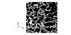
- FIG. 2 is a two-dimensional image in which the microstructure of a cold-rolled steel sheet according to one embodiment of the present invention is binarized.
- FIG. 2 is a frequency spectrum diagram obtained by performing a two-dimensional discrete Fourier transform on the two-dimensional image of FIG. 1.
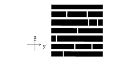
- FIG. 3 is an exemplary schematic diagram of a two-dimensional image in which a microstructure of a cold-rolled steel sheet is binarized.
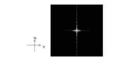
- FIG. 4 is a frequency spectrum diagram obtained by performing a two-dimensional discrete Fourier transform on the two-dimensional image of FIG. 3.
- FIG. 3 is an exemplary schematic diagram of a two-dimensional image in which a microstructure of a cold-rolled steel sheet is binarized.
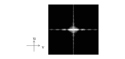
- 6 is a frequency spectrum diagram obtained by performing a two-dimensional discrete Fourier transform on the two-dimensional image of FIG. 5.
- 4 is a graph showing the relationship between the degree of heterogeneity ⁇ and the bake hardening amount BH.
- 5 is a graph showing the relationship between the degree of inhomogeneity ⁇ and the ratio of the minimum bending radius after bake hardening to the plate thickness, R / t.
- the cold rolled steel sheet according to the embodiment of the present invention is C: 0.05 to 0.30%, Si: 0.200 to 2.000%, Mn: 2.00 to 4.00%, P: 0.100% or less, S: 0.010% or less, Al: 0.001 to 2.000%, N: 0.010% or less Ti: 0 to 0.100%, Nb: 0 to 0.100%, V: 0 to 0.100%, Cu: 0 to 1.000%, Ni: 0 to 1.000%, Mo: 0 to 1.000%, Cr: 0 to 1.000%, W: 0 to 0.005%, Ca: 0 to 0.005%, Mg: 0 to 0.005%, REM: 0-0.010%, B: 0 to 0.0030%, , The balance consisting of Fe and impurities, 20% or more and 70% or less of ferrite and 30% or more of tempered martensite in area ratio, The sum of ferrite and tempered martensite is 90% or more; In a thickness
- a microstructure image of 30 ⁇ m ⁇ 30 ⁇ m obtained by photographing at a magnification of 2000 times is arranged in an xy coordinate system in which the thickness direction is the x-axis and the rolling direction is the y-axis. 1024 in the direction and 1024 in the y-axis direction to form 1024 ⁇ 1024 divided regions, and the value in each of the divided regions is set to “1” when the structure is ferrite, and to “0” otherwise.
- a two-dimensional image is created by performing two gradations, and the heterogeneity ⁇ defined by the expression (1) with respect to the two-dimensional image is 1.20 or less.
- f (x, y) represents the gradation of the coordinates (x, y) of the two-dimensional image.
- the present inventors have defined the degree of heterogeneity ⁇ defined by the above equation to be 1.20 or less in the steel sheet according to the present embodiment. The present inventors have found that when the heterogeneity ⁇ is 1.20 or less, the bake hardenability and the bendability after bake hardening of the cold-rolled steel sheet can be significantly improved.
- the heterogeneity ⁇ is set to 1.20 or less in a cold-rolled steel sheet including a composite structure containing ferrite and tempered martensite
- ferrite is finely divided in a rolling direction and a thickness direction of the cold-rolled steel sheet by tempered martensite.
- a homogeneously divided crosslinked structure is formed.
- the “crosslinked structure in which ferrite is finely and homogeneously divided in the rolling direction and the thickness direction of the cold-rolled steel sheet” means that the tempered martensite is spread inside the steel sheet in the rolling direction and the thickness direction of the steel sheet. Are randomly connected and ferrite is finely and uniformly dispersed therein.
- this crosslinked structure is merely an example of the structure of the structure in the steel sheet having the degree of heterogeneity ⁇ of 1.20. In order to obtain a structure in which the degree of inhomogeneity ⁇ is 1.20 or less, it is necessary to control manufacturing conditions described later.
- the quantification of the crosslinked structure by the Fourier transform will be described in detail.
- the sheet thickness of 1 is photographed in gray scale (256 gradations) at an observation magnification of 2000 ⁇ .
- the obtained microstructure image is arranged in an xy coordinate system in which the thickness direction is the x-axis and the rolling direction is the y-axis, and has 1024 ⁇ 1024 pixels (corresponding to the divided area).
- a value in each of the 1024 ⁇ 1024 pixels is set to “1” when the structure is ferrite, and is set to “0” otherwise, to create a two-dimensional image to create a two-dimensional image.
- the above microstructure image is, from the surface in the thickness section perpendicular to the width direction of the steel sheet at the center position of the width of the cold-rolled steel sheet, from 1/4 of the thickness from the surface.
- a microstructure image of 30 ⁇ m ⁇ 30 ⁇ m obtained by photographing a tissue at a position up to / at a magnification of 2000 ⁇ may be used.
- the image processing of the two-gradation can be performed by using, for example, image analysis software ImageJ.
- Each pixel is subjected to a binarization process so as to be black when the structure is ferrite and white when not.
- FIG. 1 shows an example of a two-dimensional image obtained in this manner.
- FIG. 1 is a two-dimensional image in which the microstructure of a cold-rolled steel sheet according to one embodiment of the present invention is binarized.
- the x-axis in FIG. 1 corresponds to the thickness direction
- the y-axis corresponds to the rolling direction.
- a black part indicates ferrite
- a white part indicates tempered martensite.
- the black ferrite phase is finely and uniformly divided in the rolling direction and the thickness direction of the cold-rolled steel sheet by the white tempered martensite phase, and it is understood that a crosslinked structure is formed. .
- f (x, y) represents the gradation of the pixel at the coordinates (x, y).
- a two-dimensional discrete Fourier transform (2D ⁇ ⁇ DFT) defined by equation (4) is performed on the obtained two-dimensional data.
- F (u, v) is a two-dimensional frequency spectrum after two-dimensional discrete Fourier transform of the two-dimensional data f (x, y).
- the frequency spectrum F (u, v) is generally a complex number and includes information on the periodicity and regularity of the two-dimensional data f (x, y).
- the frequency spectrum F (u, v) includes information on the periodicity and regularity of the structure of ferrite and tempered martensite in a two-dimensional image as shown in FIG.
- FIG. 2 is a frequency spectrum diagram obtained by performing a two-dimensional discrete Fourier transform on the two-dimensional image of FIG.
- the horizontal axis is the v axis
- the vertical axis is the u axis
- the frequency spectrum diagram of FIG. 2 is a black-and-white gradation image (grayscale image), in which the maximum value of the spectrum intensity is represented by white and the minimum value is represented by black.
- a portion having a high spectral intensity (white portion in FIG. 2) has a shape extending from the center in the v-axis and u-axis directions, and the boundary is not clear.
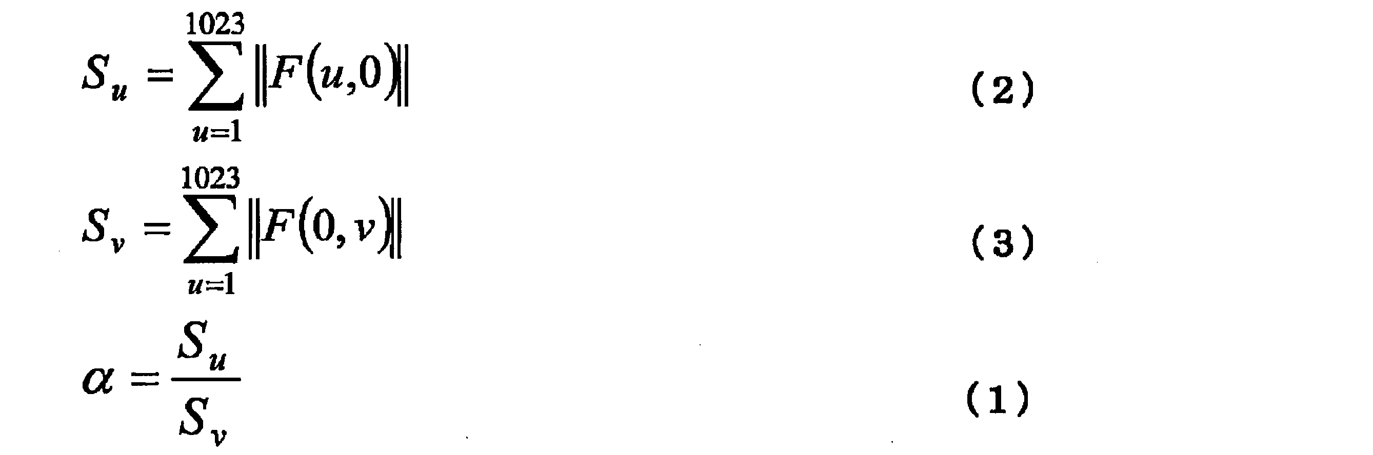
- the sum Su of the absolute value of the spectrum on the u axis (that is, the spectrum intensity) is defined by Expression (2).
- the sum Sv of the absolute values of the spectra on the v axis is defined by Expression (3).
- the ratio of Su to Sv is defined by equation (1) and is referred to as heterogeneity ⁇ in the present invention.
- the absolute value of the spectrum at the coordinates (0, 0) in the (u, v) space is not included in the sum of Expressions (2) and (3) that define Su and Sv.
- the microstructure shown in FIG. As described above, the structure 1 has a crosslinked structure in which ferrite is divided by tempered martensite. Also, the frequency spectrum diagram of the tissue 1 (FIG. 2) has a shape in which the white portion extends from the center of the image along the u-axis and v-axis directions, as described above.
- FIGS. 3 and 5 are exemplary schematic diagrams of a two-dimensional image in which the microstructure of a cold-rolled steel sheet is made into two gradations. 3 and 5, the black part indicates ferrite, and the white part indicates tempered martensite.
- FIGS. 4 and 6 are frequency spectrum diagrams obtained by subjecting the two-dimensional images of FIGS. 3 and 5 to two-dimensional discrete Fourier transform. Referring to FIGS. 3 and 5, the two-dimensional image of FIG.
- the structure of the cold-rolled steel sheet has a finer and more homogeneously crosslinked structure. It can be seen that it has.
- the heterogeneity ⁇ is calculated for the tissue 1 according to the embodiment of the present invention shown in FIG. 1, it is 1.14, which is controlled within a range of 1.20 or less.
- the bake hardening amount of the structure 1 is 105 MPa, and similarly, the ratio of the minimum bending radius to the thickness of the structure 1 after the bake hardening is 0.4. It can be evaluated that the smaller the minimum bending radius / thickness ratio, the better the bendability after bake hardening. Note that these values are measured under the same conditions as in the examples described later.
- FIG. 7 is a graph showing the relationship between the degree of heterogeneity ⁇ and the bake hardening amount BH.
- FIG. 8 is a graph showing the relationship between the degree of heterogeneity ⁇ and the ratio of the minimum bending radius after bake hardening to the plate thickness, R / t. 7 and 8 produce a plurality of cold rolled steel sheets having a chemical composition and structure within the scope of the embodiments of the invention described above and having different ⁇ , and then 3 is a plot of data obtained by performing the same bake hardening treatment and bending test as in the examples. Referring to FIGS.
- C (C: 0.05% to 0.30%) C has the effect of increasing the hardenability and increasing the strength by incorporating it into the martensite structure. In addition, it has the effect of improving bake hardenability.
- the C content is set to 0.05% or more, preferably 0.07% or more, and more preferably 0.09% or more.
- the C content is set to 0.30% or less, preferably 0.20% or less, and more preferably 0.14% or less.
- Si 0.200% to 2.000%
- Si is an element necessary for suppressing the formation of carbides and securing solid solution C necessary for bake hardening. If the Si content is less than 0.200%, a sufficient effect may not be obtained. Therefore, the Si content is set to 0.200% or more. Si is also useful for increasing the strength of a steel sheet having excellent bake hardening. In order to exhibit this effect effectively, the Si content is preferably 0.500% or more, more preferably 0.800% or more. On the other hand, when the Si content is more than 2.000%, the surface properties are degraded, and the effect of addition is saturated, so that the cost is unnecessarily increased. Therefore, the Si content is set to 2.000% or less, preferably 1.500% or less, and more preferably 1.100% or less.
- Mn is a hardenability improving element and is useful for increasing the strength of a steel sheet.
- the Mn content is set to 2.00% or more, preferably 2.30% or more, and more preferably 2.60% or more.
- the Mn content is set to 4.00% or less, preferably 3.50% or less, and more preferably 3.00% or less.
- Al 0.001% to 2.000%
- Al content is set to 0.001% or more, preferably 0.010% or more, and more preferably 0.020% or more.
- the Al content is set to 2.000% or less, preferably 1.000% or less, and more preferably 0.030% or less.
- P 0.100% or less
- P is not an essential element and is contained, for example, as an impurity in steel. From the viewpoint of weldability, the lower the P content, the better. In particular, when the P content exceeds 0.100%, the weldability is significantly reduced. Therefore, the P content is set to 0.100% or less, preferably 0.030% or less, and more preferably 0.020% or less. Reducing the P content is costly and attempting to reduce it to less than 0.0001% will significantly increase costs. Therefore, the P content may be 0.0001% or more, or may be 0.010% or more. Further, since P contributes to improvement in strength, from such a viewpoint, the P content may be 0.0001% or more, or may be 0.010% or more.
- S is not an essential element but is contained as an impurity in steel, for example. From the viewpoint of weldability, the lower the S content, the better. As the S content increases, the amount of MnS precipitated increases, and the low-temperature toughness decreases. In particular, when the S content exceeds 0.010%, the weldability and the low-temperature toughness are significantly reduced. Therefore, the S content is set to 0.010% or less, preferably 0.007% or less, and more preferably 0.003% or less. Cost reduction is required to reduce the S content, and an attempt to reduce the content to less than 0.0001% significantly increases the cost. Therefore, the S content may be 0.0001% or more, or may be 0.003% or more.
- N is not an essential element and is contained, for example, as an impurity in steel. From the viewpoint of weldability, the lower the N content, the better. In particular, when the N content exceeds 0.010%, the weldability is significantly reduced. Therefore, the N content is set to 0.010% or less, preferably 0.006% or less, and more preferably 0.003% or less. Reducing the N content is costly, and attempting to reduce it to less than 0.0001% significantly increases the cost. Therefore, the N content may be 0.0001% or more.
- the basic component composition of the steel sheet according to the embodiment of the present invention and the slab used for manufacturing the same are as described above. Further, the steel sheet and the slab may contain the following optional elements as necessary.
- Ti, Nb and V contribute to improvement in strength. Therefore, Ti, Nb or V or any combination thereof may be contained.
- the content of Ti, Nb or V, or the total content of any combination of two or more thereof is preferably 0.003% or more, more preferably 0.010%.
- the Ti content, the Nb content or the V content, or the total content of any combination of two or more thereof is set to 0.100% or less, more preferably 0.030% or less.
- the limiting ranges in the case of each component alone are: Ti: 0.003% to 0.100%, Nb: 0.003% to 0.100%, and V: 0.003% to 0.100%.
- the total content when these are arbitrarily combined is preferably 0.003 to 0.100%.
- Cu, Ni, Mo and Cr contribute to improvement in strength. Therefore, Cu, Ni, Mo, or Cr or any combination thereof may be contained.
- the content of Cu, Ni, Mo and Cr is preferably 0.005 to 1.000% in the case of each component alone, and 0.010% to 1.000%. Is more preferable.
- the total content when two or more selected from the group consisting of Cu, Ni, Mo and Cr are arbitrarily combined is preferably 0.005% or more and 1.000% or less. 010% or more and 1.000% or less are more preferable.
- the content of Cu, Ni, Mo, and Cr, or the total content of any combination of two or more of them is more than 1.000%, the effect of the above-described effect is saturated, and the cost is increased. Get higher. Therefore, the upper limit of the content of Cu, Ni, Mo and Cr, or the total content when two or more of these are arbitrarily combined is 1.000%. That is, Cu: 0.005% to 1.000%, Ni: 0.005% to 1.000%, Mo: 0.005% to 1.000%, and Cr: 0.005% to 1.000%. In addition, the total content when these are arbitrarily combined is preferably 0.005 to 1.000%.
- W, Ca, Mg, and REM contribute to fine dispersion of inclusions and increase toughness. Therefore, W, Ca, Mg, or REM or any combination thereof may be contained. In order to sufficiently obtain this effect, the total content of W, Ca, Mg, and REM, or any combination of two or more thereof is preferably 0.0003% or more, and more preferably 0.003% or more. And On the other hand, if the total content of W, Ca, Mg and REM exceeds 0.010%, the surface properties deteriorate.
- the total content of W, Ca, Mg and REM is set to 0.010% or less, more preferably 0.009% or less. That is, W: 0.005% or less, Ca: 0.005% or less, Mg: 0.005% or less, REM: 0.01% or less, and the total content of any two or more of these is 0. It is preferably from 0.0003 to 0.010%.
- the upper limit of the total content of any two or more of these is more preferably 0.009%, and the lower limit of the total content of any two or more of these is more preferably 0.003%.
- REM rare earth metal
- REM content means the total content of these 17 elements.
- Lanthanoids are industrially added, for example, in the form of misch metal.
- B is an element for improving hardenability, and is an element useful for increasing the strength of a steel sheet.
- B is preferably contained at 0.0001% (1 ppm) or more. However, if B is added in an amount exceeding 0.0030% (30 ppm), the above-described effect is saturated and is economically useless. Therefore, the B content is set to 0.0030% (30 ppm) or less, preferably 0.1%. 0025% (25 ppm) or less, more preferably 0.0019% (19 ppm) or less.
- the balance other than the above components consists of Fe and impurities.
- Impurities are components that are mixed due to various factors in the manufacturing process, including raw materials such as ores and scraps when industrially producing steel sheets, and are used for steel sheets according to the embodiments of the present invention. Means not components intentionally added.
- the cold-rolled steel sheet according to the embodiment of the present invention includes a composite structure containing at least two or more structures, and the distribution of the pre-strain is changed by controlling the composite structure. This has a great feature that the bake hardenability is improved. The reason for defining the area ratio for each tissue will be described. In the following description, “%”, which is a unit of the fraction of each structure included in the steel sheet, means “area%” unless otherwise specified.
- Ferrite 20% or more and 70% or less
- Ferrite is a structure having low yield stress and excellent ductility and work hardening characteristics. Therefore, when the ferrite area ratio is excessively increased, the strength before the bake hardening treatment is increased, and the yield stress after the bake hardening treatment is reduced. In this case, since the bake hardenability is greatly deteriorated, the area ratio of ferrite in the steel sheet is set to 70% or less. In order to further improve bake hardenability, the area ratio of ferrite is preferably 50% or less, more preferably 45% or less.
- the ferrite area ratio is set to 20% or more, preferably 25% or more, and more preferably 30% or more.
- Tempered martensite 30% or more
- Tempered martensite is a structure that increases the strength, bake hardenability, and bendability after bake hardening of a steel sheet. In general, baking hardenability is excellent because the carbon concentration is higher in the hard structure than in ferrite. In the embodiment of the present invention, such a hard structure needs to be tempered martensite in order to increase the amount of bake hardening, and also to improve the bendability and ultimate deformability after bake hardening. It is necessary to temper martensite as it is in the composite structure.
- the pre-strain is mostly borne by the ferrite, so that the bake hardenability of tempered martensite has not been fully utilized conventionally.
- the bake hardenability it is important that tempered martensite be deformed.
- the area ratio of tempered martensite is set to 30% or more, preferably 40% or more, and more preferably 50% or more.
- the area ratio of tempered martensite is preferably 80% or less, and more preferably 70% or less.
- the total area ratio of ferrite and tempered martensite is set to 90% or more. If the total area ratio of ferrite and tempered martensite is less than 90%, a sufficient bake hardening amount and bendability after ferrite and bake hardening cannot be obtained. Therefore, the total area ratio of ferrite and tempered martensite is 90% or more, preferably 95% or more, more preferably 97% or more, and may be 100%.
- retained austenite may be generated depending on manufacturing conditions.
- the area ratio of this structure is obtained by subtracting the area ratio of ferrite and tempered martensite measured as described above from 100%.
- the other structure that is, the structure such as retained austenite, is small, the effect can be ignored.
- 90% or more, preferably 95% or more of the structure is composed of ferrite and tempered martensite, and thus the influence of retained austenite may be ignored.
- carbides such as cementite are precipitated from martensite or ferrite during the tempering step.
- Such carbides are difficult to measure as an area ratio because they are deposited in fine and large quantities. Therefore, when ferrite and tempered martensite contain carbide, the area ratio of these structures is measured as the area ratio of the parent phase containing the carbide.
- the area ratio of ferrite and the area ratio of tempered martensite are determined as follows. First, a sample was taken using the thickness cross section perpendicular to the rolling direction of the steel sheet as an observation surface, the observation surface was polished, and the structure at a quarter position of the thickness of the steel plate was subjected to SEM-EBSD (electron microscopy) at a magnification of 5000 times. Observation with a scanning electron microscope equipped with an X-ray back-scattering diffractometer), image analysis of the image in a visual field of 100 ⁇ m ⁇ 100 ⁇ m and measurement of the area ratio of ferrite. Is determined as the area ratio of ferrite.
- SEM-EBSD electron microscopy
- a secondary electron image of the SEM is taken in a region from the depth of 3 t / 8 to t / 2 from the surface of the steel plate.
- the magnification is 1500 times.
- the white portion of the obtained image data is a hard tissue and the black portion is ferrite
- the area ratio of the hard tissue is determined based on the image data.
- the tempered state of the hard tissue is determined as follows. When observing the secondary electron image of the SEM, if the contrast of laths and blocks contained in martensite is clear or observed at, for example, 5000 times or 10000 times, if fine carbides are precipitated in the structure, In other words, it can be said that tempered, that is, the hard structure is determined to be tempered martensite.
- the heterogeneity ⁇ defined by the equation (1) is 1.20 or less.
- the degree of heterogeneity ⁇ is determined by the following method. In the thickness section perpendicular to the sheet width direction of the steel sheet at a position of 1/8 to 7/8 of the sheet width of the cold-rolled steel sheet, the structure at a position of 1/4 to 3/8 of the sheet thickness from the surface is 2000 Shoot at double magnification.
- the obtained microstructure image of 30 ⁇ m ⁇ 30 ⁇ m is arranged in an xy coordinate system where the thickness direction is the x-axis and the rolling direction is the y-axis, and 1024 ⁇ 1024 pixels are represented in gray scale.
- the microstructure image represented by the gray scale (256 gradations) is obtained from the cross section of the cold rolled steel sheet in the plane including the sheet thickness direction and the rolling direction.
- each of the 1024 ⁇ 1024 divided regions is set to “1” when the structure is ferrite, and is set to “0” otherwise, to create a two-dimensional image, thereby creating a two-dimensional image.
- the degree of heterogeneity ⁇ defined by the expression (1) is obtained from the microstructure image binarized.
- the above microstructure image is, from the surface in the thickness section perpendicular to the width direction of the steel sheet at the center position of the width of the cold-rolled steel sheet, from 1/4 of the thickness from the surface.
- a microstructure image of 30 ⁇ m ⁇ 30 ⁇ m obtained by photographing a tissue at a position up to / at a magnification of 2000 ⁇ may be used.
- f (x, y) represents the gradation of the coordinates (x, y) of the two-dimensional image.
- ⁇ and bake hardenability have a relationship shown in FIG. 7, and ⁇ and bendability after bake harden have a relationship shown in FIG.
- the bake hardening amount BH becomes 100 MP or more as shown in FIGS. 7 and 8, and the minimum bending radius after bake hardening.
- R / t which is the ratio between the thickness and the plate thickness, is less than 1.0. Therefore, the cold rolled steel sheet according to one embodiment of the present invention has excellent bake hardenability and impact resistance.
- ⁇ is preferably 1.10 or less, more preferably 1.05 or less.
- the lower limit of ⁇ is not particularly specified, but is generally 0.90 or more.
- the cold rolled steel sheet according to one embodiment of the present invention has excellent paint bake hardening performance and has excellent impact resistance. For this reason, it is preferable to use the cold-rolled steel sheet of the present embodiment for a structural member such as an automobile which is used after being pressed.
- the cold-rolled steel sheet according to the present embodiment preferably has a tensile strength of 780 MPa or more, more preferably 800 MPa or more, and still more preferably 900 MPa or more.
- the cold rolled steel sheet according to the present embodiment preferably has a bake hardening amount of 100 MPa or more, more preferably 120 MPa or more, and even more preferably 150 MPa or more.
- the cold-rolled steel sheet according to the present embodiment preferably has a breaking elongation of 10% or more, more preferably 12% or more.
- the cold rolled steel sheet according to the present embodiment has excellent bendability after bake hardening, preferably has a minimum bending radius / thickness ratio of less than 1.0, and more preferably has a minimum bending radius of 0.5 or less. / Thickness ratio.
- the following description is intended to exemplify a characteristic method for manufacturing the cold-rolled steel sheet according to the embodiment of the present invention, and the cold-rolled steel sheet is manufactured by a manufacturing method as described below. It is not intended to be limited to those.
- the manufacturing method is a step of forming a slab by casting molten steel having the chemical composition described above, A rough rolling step of roughly rolling the slab in a temperature range of 1050 ° C. or more and 1250 ° C. or less, wherein the rough rolling is performed by reverse rolling in which a rolling reduction per pass is 30% or less; (I) and (ii): (I) One reciprocation in which the reduction rate of the first pass is 20% or more and 30% or less, the reduction rate of the second pass is 15% or less, and (ii) The reduction rate of the third pass is 15% or less, and A rough rolling process in which a rolling reduction of 20% or more and 30% or less and a total of two reciprocations of one reciprocation as one set includes three or more sets, and a reduction ratio between two passes during one reciprocation is 5% or more; A finish rolling step which starts less than 5 seconds after the rough rolling step and finish-rolls the rough-rolled steel sheet in a temperature range of 850 ° C.
- each step will be described.
- the slab can be produced, for example, by using a converter or an electric furnace to melt molten steel having the chemical composition of the steel sheet according to the embodiment of the present invention described above, and by a continuous casting method.
- a continuous casting method an ingot making method, a thin slab casting method, or the like may be adopted.
- the slab may be heated to a temperature range from 1000 ° C. to 1300 ° C. before performing the following rough rolling step.
- the holding time after heating is not particularly limited, but is preferably 30 minutes or more in order to reach a predetermined temperature up to the center of the slab. In order to suppress excessive scale loss, the time is preferably 10 hours or less, more preferably 5 hours or less. In the case where direct rolling or direct rolling is performed and the temperature of the slab after casting is 1050 ° C. or more and 1250 ° C. or less, the slab may be subjected to the following rough rolling step without heating and holding.
- the portion where the alloy element such as Mn is concentrated is inward from both surfaces of the slab. It grows almost vertically in the form of a comb and is arranged in a plurality.
- the surface of the slab is extended in the rolling direction in each pass of the rolling.
- the rolling direction is a direction in which the slab advances with respect to the rolling rolls.
- the Mn segregation portion In the case of so-called unidirectional rolling, in which the direction of travel of the slab in each pass of the rough rolling is always the same direction, the Mn segregation portion is gradually inclined in the same direction for each pass while maintaining a nearly straight state. It is becoming. Further, at the end of the rough rolling, the Mn segregation portion is in a posture substantially parallel to the surface of the slab while maintaining a substantially straight state, and flat micro segregation is formed.
- the Mn segregated portion inclined in the immediately preceding pass is inclined in the opposite direction in the next pass.
- the Mn segregated portion has a bent shape.
- the Mn segregation portion has a complicatedly bent shape by repeatedly performing each pass in the opposite direction alternately.
- the rough rolling temperature is set to 1050 ° C. or more and 1250 ° C. or less.
- the lower limit of the rough rolling temperature is preferably 1100 ° C.
- the upper limit of the rough rolling temperature is preferably 1200 ° C.
- the rolling reduction in one pass in the rough rolling is set to 30% or less.
- the lower the rolling reduction the smaller the shear strain during rolling, and the lower the rolling reduction is, since the formation of a band structure is suppressed, but the lower limit of the rolling reduction is not particularly defined, but is preferably 10% or more from the viewpoint of productivity, More preferably, it is 15%.
- the rolling reduction is controlled in each pass to change the shear stress during rolling. There must be.
- the rolling is performed by rolling three or more sets in which a total of two reciprocations of the following (i) and (ii) are set as one set.
- the passes in which the traveling directions are opposite to each other be performed the same number of times, that is, the total number of passes is an even number.
- the entry side and the exit side of the rough rolling are located on opposite sides of the roll. Therefore, the number of passes (rolling) in the direction from the entry side to the exit side of the rough rolling increases once. Then, in the last pass (rolling), the Mn segregated portion becomes plate-like, and it is difficult to form a network distribution of Mn.
- multi-stage tandem rolling in finish rolling is effective, but flat micro-segregation is easily formed by tandem rolling.
- the holding time from the rough rolling to the finish rolling is preferably less than 5 seconds, and 3 It is more preferable to set the time to seconds or less.
- the finish rolling After the reverse rolling in the rough rolling, by increasing the rolling reduction of the tandem rolling in the finish rolling, in order to narrow the interval of the Mn segregation zone caused by the secondary dendrite arm, the finish rolling is performed four or more consecutive times. It is preferably carried out on a rolling stand.
- the finish rolling completion temperature is set to 850 ° C. or higher, preferably 900 ° C. or higher.
- the finish rolling temperature is set to 1050 ° C. or less.
- the rough rolled steel sheet may be reheated after the rough rolling step and before the finish rolling step.
- the rolling reduction of the first stand in the finish rolling is preferably 10% or less.
- the winding temperature is preferably 200 ° C or lower.
- austenite is transformed into hard martensite during cooling, and a large amount of strain is introduced into soft ferrite in the vicinity of martensite due to the introduction of transformation strain at that time. It contributes to miniaturization and homogenization of recrystallized ferrite.
- the winding temperature is 200 ° C. or lower, preferably 100 ° C. or lower, and more preferably 50 ° C. or lower.
- the bendability must be excellent in both the processing effect ability and the ultimate deformability, but the martensite finely divides the ferrite and takes a cross-linked structure to improve the work hardening ability of the ferrite, and furthermore, for a homogeneous structure Excellent in ultimate deformability.
- the rolling reduction of the cold rolling is important to reduce the rolling reduction of the cold rolling.
- the upper limit of the rolling reduction of the cold rolling is 30%, preferably 20%. If the rolling reduction of the cold rolling exceeds 30%, the crosslinked structure of martensite and ferrite is crushed in the sheet thickness direction, and the heterogeneity ⁇ does not satisfy the condition specified in the present invention.
- the lower limit of the cold rolling is 5%, preferably 7%, and more preferably 10%. Making the rolling reduction of the cold rolling 30% or less is an important requirement for satisfying the condition of the heterogeneity ⁇ defined in the present invention.
- the steel sheet obtained through the cold rolling step is subjected to an annealing treatment. Heating at the annealing temperature is performed in a temperature range of Ac 1 to 1000 ° C. for 10 seconds to 1000 seconds. This temperature range determines the area ratio between the ferrite and the hard structure.
- the upper limit of the temperature range for the annealing treatment is preferably 870 ° C, more preferably 850 ° C.
- the annealing time is set to 10 seconds or more in order to sufficiently recrystallize the cold-worked ferrite and to easily control the area ratio between the ferrite and the hard structure. On the other hand, if the annealing time exceeds 1000 seconds, the productivity deteriorates. Therefore, the annealing time is set to 10 seconds or more and 1000 seconds or less.
- the upper limit of the annealing time is preferably 300 seconds.
- the lower limit of the annealing time is preferably 200 seconds.
- Ac 1 point is calculated by the following equation.
- Ac 1 751-16 ⁇ C + 35 ⁇ Si-28 ⁇ Mn-16 ⁇ Ni + 13 ⁇ Cr-6 ⁇ Cu + 3 ⁇ Mo
- C, Si, Mn, Ni, Cr, Cu, and Mo are the contents (% by mass) of each element, and 0% by mass is substituted for the element not contained.
- cooling is performed at a cooling rate of 10 ° C./sec or more and 200 ° C./sec or less.
- the faster the cooling rate the better to freeze the tissue and effectively cause martensitic transformation.
- the cooling rate is less than 10 ° C./sec, martensite is not sufficiently generated, and the desired structure cannot be controlled.
- the cooling rate after annealing is set to 10 ° C./sec or more and 200 ° C./sec or less.
- the upper limit of the cooling rate after annealing is preferably 50 ° C./sec.
- the lower limit of the cooling rate after annealing is preferably 10 ° C./sec.
- the cooling rate differs from the average cooling rate and means that the cooling rate does not fall below 10 ° C./sec in any temperature range during cooling.
- the cooling stop temperature is 200 ° C. or less. This is for generating martensite after holding the annealing temperature. At this time, a step of stopping cooling at a temperature of 200 ° C. or more and 500 ° C. or less and holding the temperature for 10 seconds or more and 1000 seconds or less may be included.
- the cooling stop temperature is preferably 55 ° C. or lower, more preferably 45 ° C. or lower.
- the obtained steel sheet is held in a temperature range of 200 ° C. or more and 350 ° C. or less by heating in the tempering step.
- the holding temperature is preferably from 250 ° C. to 300 ° C. If the holding temperature is lower than 200 ° C., the pre-strain distribution does not change because martensite is not tempered. If the temperature is higher than 350 ° C., the precipitation of coarse carbides reduces the total amount of solute carbon, so that the bake hardenability decreases.
- the holding temperature is higher than the recrystallization temperature of ferrite, the distribution of the interface between the ferrite and the mother phase changes due to the recrystallized ferrite generated in the mother phase, and as a result, the cross-linked structure of martensite and ferrite is divided or May collapse.
- the holding time is set to 100 seconds or more. Thereafter, from the viewpoint of productivity, cooling is performed at an average cooling rate of 2 ° C./sec or more to 100 ° C. or less.
- the cooling stop temperature is preferably 50 ° C or lower, more preferably 45 ° C or lower.
- the cold rolled steel sheet manufactured by the above method may optionally be subjected to final skin pass rolling (temper rolling).
- final skin pass rolling By performing skin pass rolling, even if there is no pre-strain, the steel sheet is strained, so that the bake hardenability can be improved.
- the rolling reduction In order to uniformly introduce strain into the steel sheet, the rolling reduction is set to 0.1% or more, and it is difficult to control the thickness of the steel sheet. Therefore, the upper limit is preferably set to 0.5%.
- the cold-rolled steel sheet according to the embodiment of the present invention can be manufactured.
- the conditions in the examples are one condition examples adopted for confirming the operability and effects of the present invention, and the present invention is not limited to these one condition examples.
- the present invention can employ various conditions as long as the object of the present invention is achieved without departing from the gist of the present invention.
- a slab having the chemical composition shown in Table 1 was manufactured, and the slab was heated to 1300 ° C. for 1 hour, and then subjected to rough rolling and finish rolling under the conditions shown in Table 2, and then the steel sheet was wound up and wound up as shown in Table 2. It was kept at the removal temperature for one hour to obtain a hot-rolled steel sheet having a thickness of 2 mm. Thereafter, the hot-rolled steel sheet was pickled and cold-rolled at a rolling reduction shown in Table 2 to obtain a cold-rolled steel sheet having a sheet thickness shown in Table 2. Subsequently, annealing, tempering and / or skin pass rolling were performed under the conditions shown in Table 2.
- the steel structure of the obtained cold-rolled steel sheet was observed.
- the area ratio of ferrite, the area ratio of tempered martensite, and the degree of heterogeneity ⁇ were determined by the above-described methods.
- the area ratio of ferrite and the area ratio of tempered martensite were determined as follows. First, a sample was taken using the thickness section perpendicular to the rolling direction of the steel sheet as an observation surface, the observation surface was polished, and the structure at a quarter position of the thickness of the steel plate was observed with a SEM-EBSD at a magnification of 5000 times. Then, it was image-analyzed in a visual field of 100 ⁇ m ⁇ 100 ⁇ m to measure the area ratio of ferrite, and the average of these measured values in any five visual fields was determined as the area ratio of ferrite.
- the tensile strength TS, breaking elongation EL, bake hardening amount BH, and minimum bending radius R of the obtained cold-rolled steel sheet were measured.
- a JIS No. 5 tensile test piece having a longitudinal direction perpendicular to the rolling direction was sampled and subjected to a tensile test in accordance with JIS Z # 2241.
- BH is a value obtained by subtracting the stress at the time of applying a 2% pre-strain from the stress at the time of re-tensioning a test piece heat treated at 170 ° C.
- the tensile strength is 780 MPa or more.
- the elongation at break is preferably 10% or more in order to facilitate molding.
- BH is less than 100 MPa, it is difficult to mold, and the strength after molding is low. Therefore, in order to have excellent bake hardenability, BH is preferably 100 MPa or more.
- RR / t which is the ratio between the minimum bending radius and the plate thickness, is used as an index for evaluating the bendability after the paint bake hardening treatment.
- the minimum bending radius R was measured using a V-block method defined in JIS Z 2248 (tip angle of the fitting: 90 °, tip radius R: changed from 0.5 mm to 0.5 mm pitch) with a specimen width of 30 mm. Carried out. If the ratio of the minimum bending radius to the plate thickness, R / t, is not less than 1.0, the test specimen after the paint baking hardening treatment is immediately broken by the bending stress generated during the bellows-like deformation at the time of collision. There are cases. That is, the collision performance as a component is poor. Therefore, it is preferable that R / t, which is the ratio between the minimum bending radius after the BH measurement and the plate thickness, is less than 1.0.
- Comparative Example 2 the tempered martensite did not have a desired area ratio because the tempering holding time was too short, and the BH of the steel was low and the R / t was high.
- Comparative Example 4 the cross-linking structure of martensite and ferrite could not be maintained because the rolling reduction of the cold rolling was high, and as a result, the heterogeneity ⁇ increased, the BH was low, and the R / t was high.
- Comparative Example 5 the tempered martensite did not have a desired area ratio because the tempering holding temperature was low, and the BH of the steel was low and the R / t was high.
- Comparative Example 12 coarse carbides were precipitated because the tempering holding temperature was high, and the crosslinked structure of martensite and ferrite could not be maintained due to the formation of recrystallized ferrite. BH was low and R / t was high. In Comparative Example 13, since the C content was low, ferrite and tempered martensite did not have a desired area ratio, and the TS and BH of the steel were low. In Comparative Example 14, coarse carbides were precipitated because the Si content was low, and the BH was low and the R / t was high. In Comparative Example 16, since the completion temperature of the finish rolling was low, the heterogeneity ⁇ was large, the BH was low, and the R / t was high.
- Comparative Example 18 since the Mn content was low, tempered martensite did not have a desired area ratio, and TS and BH were low and R / t was high.
- Comparative Example 19 the difference in rolling reduction between the two passes included in one round trip of the rough rolling was low, so that the heterogeneity ⁇ was large, the BH was low, and the R / t was high.
- Comparative Example 21 since the rolling reduction of the rough rolling was high, the heterogeneity ⁇ was large, the BH was low, and the R / t was high.
- Comparative Example 24 since the winding temperature was high, the formation of martensite was suppressed, and as a result, the heterogeneity ⁇ increased, the BH was low, and the R / t was high.
- Comparative Example 26 the crosslinked structure of tempered martensite and ferrite could not be obtained because the number of rough rolling was small, the heterogeneity ⁇ increased, the BH was low, and the R / t was high.
- Comparative Example 28 since the holding time from rough rolling to finish rolling was long, a crosslinked structure of tempered martensite and ferrite could not be obtained, the heterogeneity ⁇ increased, the BH was low, and the R / t was high. .
- Comparative Example 31 since the formation of martensite in the hot-rolled steel sheet was suppressed because the winding temperature was high, the amount of strain introduced into the ferrite was small, and as a result, the heterogeneity ⁇ increased, and the BH was low and R / T was high.
- Comparative Example 32 the cross-linking structure of martensite and ferrite could not be maintained due to the high rolling reduction of the cold rolling, and as a result, the heterogeneity ⁇ increased, the BH was low, and the R / t was high.
- the cold-rolled steel sheet of the present invention can be used as a structural member of an automobile particularly in the automobile industry.
Landscapes
- Chemical & Material Sciences (AREA)
- Engineering & Computer Science (AREA)
- Mechanical Engineering (AREA)
- Materials Engineering (AREA)
- Metallurgy (AREA)
- Organic Chemistry (AREA)
- Physics & Mathematics (AREA)
- Thermal Sciences (AREA)
- Crystallography & Structural Chemistry (AREA)
- Heat Treatment Of Sheet Steel (AREA)
Abstract
本願発明に係る焼付硬化量が高くかつ焼付硬化後の曲げ性に優れる冷延鋼板は、所定の組成を有し、面積率で、20%以上70%以下のフェライト、及び30%以上の焼戻しマルテンサイトを含有し、フェライト及び焼戻しマルテンサイトの合計が90%以上であり、組織を2000倍の倍率で撮影して得られた30μm×30μmのミクロ組織画像を、板厚方向をx軸としかつ圧延方向をy軸とするxy座標系に配置し、次いでミクロ組織画像をx軸方向に1024個、y軸方向に1024個分割して1024×1024個の分割領域を形成し、分割領域のそれぞれにおける値を組織がフェライトである場合に「1」、そうでない場合に「0」として2階調化して2次元画像を作成し、2次元画像に対して2次元離散フーリエ変換を実施したときに得られる不均質度αが1.20以下である。
Description
本発明は、冷延鋼板、具体的には主としてプレス加工されて使用される自動車等の構造部材に好適な、塗装焼付硬化性能と耐衝撃性に優れた冷延鋼板に関するものである。本願は、2018年10月4日に、日本に出願された特願2018-189164号に基づき優先権を主張し、その内容をここに援用する。
近年、自動車の燃費向上に寄与する軽量化の観点から高強度鋼板の適用が拡大しているが、自動車用部品の多くはプレス成形により製造されるため、高い強度と同時に優れた成形性が要求される。また、乗員の安全確保という目的から、耐衝突性の向上も望まれており、高強度を有しながらも衝突時に発生する曲げ応力に対して優れた曲げ変形能を有する素材が求められる。そのため、成形加工時には比較的軟質で成形しやすく、成形加工後、塗装焼付時の焼付硬化量が大きく、かつ焼付硬化後の曲げ性に優れた素材が求められている。
前記焼付硬化は、プレス成形(以下、「予ひずみ」ともいう)によって入る転位(塑性変形の素過程となる線欠陥)に、侵入型元素(主に炭素)が移動・固着することでその運動を阻害し、強度が上昇する現象で、ひずみ時効とも呼ばれる。焼付硬化量は軟鋼板などのフェライト単相組織においては、固溶炭素の量で制御できる。
一方、高強度鋼板においては、加工性を確保するために、その多くが硬質組織(マルテンサイト)と、軟質組織(フェライト)を含有する複合組織である。その中で、高い焼付硬化性を担うのは、固溶炭素を多く含む硬質組織(マルテンサイト)である。しかしながら、固溶炭素を多く含む硬質組織は高強度を実現できるものの、焼付硬化性と焼付硬化後の曲げ性を両立させることは難しかった。すなわち、マルテンサイトはフェライトに比べ固溶炭素量が多く転位密度も高いために焼付硬化性に優れるが、曲げ性に劣る。
例えば特許文献1には、ベイナイト及びマルテンサイトからなる組織を主として含み、フェライトの面積率を5%以下に制限することで高い焼付硬化性を確保した冷延鋼板が開示されている。しかし、この鋼板はベイナイト及びマルテンサイトの硬質組織を多く含むため、予ひずみが2%以上では、複合組織中で硬質相と軟質相のそれぞれで焼付硬化が起こる。このため、焼付硬化処理後の組織は強度が不均一となることから、優れた焼付硬化後の曲げ性は発現しない。
特許文献2には、焼戻しマルテンサイト又は焼戻しベイナイトを含むことで加工性及び焼付硬化性を向上させた鋼板が開示されている。しかし、特許文献2では、焼付硬化後の曲げ性を改善するという観点からは何ら十分な検討がなされていない。
したがって、本発明は、焼付硬化量が高くかつ焼付硬化後の曲げ性に優れる冷延鋼板を提供することを目的とする。
本発明者らは、上記目的を達成するために、焼付硬化量と焼付硬化後の曲げ性について調査した。その結果、本発明者らは、フェライトと焼戻しマルテンサイトとを含む冷延鋼板の組織において、フェライトが焼戻しマルテンサイトにより圧延方向及び板厚方向に微細かつ均質に分割される架橋構造をとる場合に、当該冷延鋼板は焼付硬化量が高くかつ焼付硬化後の曲げ性に優れることを見出した。さらに、本発明者らは、冷延鋼板のミクロ組織画像を2次元フーリエ変換して得られる周波数スペクトルを利用することにより、このような架橋構造を定量化できることを見出し、本発明を完成させた。
上記目的を達成し得た冷延鋼板は、以下のとおりである。
(1)質量%で、
C:0.05~0.30%、
Si:0.200~2.000%、
Mn:2.00~4.00%、
P:0.100%以下、
S:0.010%以下、
Al:0.001~2.000%、
N:0.010%以下
Ti:0~0.100%、
Nb:0~0.100%、
V:0~0.100%、
Cu:0~1.000%、
Ni:0~1.000%、
Mo:0~1.000%、
Cr:0~1.000%、
W:0~0.005%、
Ca:0~0.005%、
Mg:0~0.005%、
REM:0~0.010%、
B:0~0.0030%、
を含有し、残部がFe及び不純物からなり、
面積率で、20%以上70%以下のフェライト、及び30%以上の焼戻しマルテンサイトを含有し、
フェライト及び焼戻しマルテンサイトの合計が90%以上であり、
前記冷延鋼板の板幅の1/8から7/8までの位置の鋼板の板幅方向に垂直な板厚断面において、表面から板厚の1/4から3/8までの位置の組織を2000倍の倍率で撮影して得られた30μm×30μmのミクロ組織画像を、板厚方向をx軸としかつ圧延方向をy軸とするxy座標系に配置し、次いで前記ミクロ組織画像をx軸方向に1024個、y軸方向に1024個分割して1024×1024個の分割領域を形成し、前記分割領域のそれぞれにおける値を組織がフェライトである場合に「1」、そうでない場合に「0」として2階調化して2次元画像を作成し、前記2次元画像に対して、式(1)で定義される不均質度αが1.20以下である、冷延鋼板。
(1)質量%で、
C:0.05~0.30%、
Si:0.200~2.000%、
Mn:2.00~4.00%、
P:0.100%以下、
S:0.010%以下、
Al:0.001~2.000%、
N:0.010%以下
Ti:0~0.100%、
Nb:0~0.100%、
V:0~0.100%、
Cu:0~1.000%、
Ni:0~1.000%、
Mo:0~1.000%、
Cr:0~1.000%、
W:0~0.005%、
Ca:0~0.005%、
Mg:0~0.005%、
REM:0~0.010%、
B:0~0.0030%、
を含有し、残部がFe及び不純物からなり、
面積率で、20%以上70%以下のフェライト、及び30%以上の焼戻しマルテンサイトを含有し、
フェライト及び焼戻しマルテンサイトの合計が90%以上であり、
前記冷延鋼板の板幅の1/8から7/8までの位置の鋼板の板幅方向に垂直な板厚断面において、表面から板厚の1/4から3/8までの位置の組織を2000倍の倍率で撮影して得られた30μm×30μmのミクロ組織画像を、板厚方向をx軸としかつ圧延方向をy軸とするxy座標系に配置し、次いで前記ミクロ組織画像をx軸方向に1024個、y軸方向に1024個分割して1024×1024個の分割領域を形成し、前記分割領域のそれぞれにおける値を組織がフェライトである場合に「1」、そうでない場合に「0」として2階調化して2次元画像を作成し、前記2次元画像に対して、式(1)で定義される不均質度αが1.20以下である、冷延鋼板。

式(1)において、Suは式(2)で定義され、Svは式(3)で定義される。

式(2)及び式(3)において、F(u,v)は式(4)で定義される。

式(4)において、f(x,y)は、前記2次元画像の座標(x,y)の階調を表す。
(2)更に、質量%で、
Ti:0.003~0.100%、
Nb:0.003~0.100%、
V:0.003~0.100%
の1種又は2種以上を合計で0.100%以下含有する、(1)に記載の冷延鋼板。
(3)前記ミクロ組織画像が、前記冷延鋼板の板幅の中央位置の鋼板の板幅方向に垂直な板厚断面において、表面から板厚の1/4から3/8までの位置の組織を2000倍の倍率で撮影して得られた30μm×30μmのミクロ組織画像である、(1)又は(2)のいずれか一項に記載の冷延鋼板。
(2)更に、質量%で、
Ti:0.003~0.100%、
Nb:0.003~0.100%、
V:0.003~0.100%
の1種又は2種以上を合計で0.100%以下含有する、(1)に記載の冷延鋼板。
(3)前記ミクロ組織画像が、前記冷延鋼板の板幅の中央位置の鋼板の板幅方向に垂直な板厚断面において、表面から板厚の1/4から3/8までの位置の組織を2000倍の倍率で撮影して得られた30μm×30μmのミクロ組織画像である、(1)又は(2)のいずれか一項に記載の冷延鋼板。
本発明によれば、フェライトが焼戻しマルテンサイトにより圧延方向及び板厚方向に微細かつ均質に分割される架橋構造を持つことで、高い焼付硬化量と焼付硬化後の曲げ性に優れた複合組織を有する冷延鋼板を提供することができる。この冷延鋼板は、プレス成形性に優れ、プレス成形後の塗装時に焼付を受けることでさらに高強度化し、その後の曲げ性にも優れる。したがって、鋼板が衝撃力を受け、蛇腹状に変形する際に生じる曲げ応力に対しても高い衝撃吸収性を有する為、自動車等の分野の構造部材として適している。
<冷延鋼板>
本発明の実施形態に係る冷延鋼板は、質量%で、
C:0.05~0.30%、
Si:0.200~2.000%、
Mn:2.00~4.00%、
P:0.100%以下、
S:0.010%以下、
Al:0.001~2.000%、
N:0.010%以下
Ti:0~0.100%、
Nb:0~0.100%、
V:0~0.100%、
Cu:0~1.000%、
Ni:0~1.000%、
Mo:0~1.000%、
Cr:0~1.000%、
W:0~0.005%、
Ca:0~0.005%、
Mg:0~0.005%、
REM:0~0.010%、
B:0~0.0030%、
を含有し、残部がFe及び不純物からなり、
面積率で、20%以上70%以下のフェライト、及び30%以上の焼戻しマルテンサイトを含有し、
フェライト及び焼戻しマルテンサイトの合計が90%以上であり、
前記冷延鋼板の板幅の1/8から7/8までの位置の鋼板の板幅方向に垂直な板厚断面において、表面から板厚の1/4から3/8までの位置の組織を2000倍の倍率で撮影して得られた30μm×30μmのミクロ組織画像を、板厚方向をx軸としかつ圧延方向をy軸とするxy座標系に配置し、次いで前記ミクロ組織画像をx軸方向に1024個、y軸方向に1024個分割して1024×1024個の分割領域を形成し、前記分割領域のそれぞれにおける値を組織がフェライトである場合に「1」、そうでない場合に「0」として2階調化して2次元画像を作成し、前記2次元画像に対して、式(1)で定義される不均質度αが1.20以下であることを特徴としている。
本発明の実施形態に係る冷延鋼板は、質量%で、
C:0.05~0.30%、
Si:0.200~2.000%、
Mn:2.00~4.00%、
P:0.100%以下、
S:0.010%以下、
Al:0.001~2.000%、
N:0.010%以下
Ti:0~0.100%、
Nb:0~0.100%、
V:0~0.100%、
Cu:0~1.000%、
Ni:0~1.000%、
Mo:0~1.000%、
Cr:0~1.000%、
W:0~0.005%、
Ca:0~0.005%、
Mg:0~0.005%、
REM:0~0.010%、
B:0~0.0030%、
を含有し、残部がFe及び不純物からなり、
面積率で、20%以上70%以下のフェライト、及び30%以上の焼戻しマルテンサイトを含有し、
フェライト及び焼戻しマルテンサイトの合計が90%以上であり、
前記冷延鋼板の板幅の1/8から7/8までの位置の鋼板の板幅方向に垂直な板厚断面において、表面から板厚の1/4から3/8までの位置の組織を2000倍の倍率で撮影して得られた30μm×30μmのミクロ組織画像を、板厚方向をx軸としかつ圧延方向をy軸とするxy座標系に配置し、次いで前記ミクロ組織画像をx軸方向に1024個、y軸方向に1024個分割して1024×1024個の分割領域を形成し、前記分割領域のそれぞれにおける値を組織がフェライトである場合に「1」、そうでない場合に「0」として2階調化して2次元画像を作成し、前記2次元画像に対して、式(1)で定義される不均質度αが1.20以下であることを特徴としている。

式(1)において、Suは式(2)で定義され、Svは式(3)で定義される。

式(2)及び式(3)において、F(u,v)は式(4)で定義される。

式(4)において、f(x,y)は、前記2次元画像の座標(x,y)の階調を表す。
例えば、フェライトとマルテンサイトを含有する複合組織を含む鋼板の焼付硬化性を向上させるためには、鋼板中のフェライト及びマルテンサイトの両方に、予ひずみを均一に導入する必要があり、また、焼付硬化後の曲げ性を向上させる観点からは、当該鋼板の組織を均質にすることが重要である。以上の知見に鑑みて、本発明者らは、本実施形態に係る鋼板では、上述の式によって定義される不均質度αを1.20以下に規定した。不均質度αが1.20以下である場合、当該冷延鋼板の焼付硬化性及び焼付硬化後の曲げ性を顕著に改善することができることを、本発明者らは見出した。
フェライトと焼戻しマルテンサイトを含有する複合組織を含む冷延鋼板において不均質度αを1.20以下とする場合、例えば、焼戻しマルテンサイトによって、冷延鋼板の圧延方向及び板厚方向にフェライトが微細かつ均質に分割した架橋構造を形成される。ここで、「冷延鋼板の圧延方向及び板厚方向にフェライトが微細かつ均質に分割した架橋構造」とは、鋼板内部において、鋼板の圧延方向及び板厚方向に広がるように、焼き戻しマルテンサイトがランダムに連結しており、その内部にフェライトが微細かつ均質に分散される構造を意図した表現である。これは、板厚方向xと圧延方向yを含む鋼板の断面から組織を観察した際、焼き戻しマルテンサイトが同一厚み領域に広がる状態が複数存在し、これらの同一厚み領域が、板厚方向xに伸びる平行線により、ランダムな配置で連結された状態となる(図3参照)。その結果、上記断面において、フェライトは、焼き戻しマルテンサイトによって微細に分割されている。ただし、この架橋構造は、不均質度αが1.20である鋼板における組織の構成の一例にすぎないことに留意されたい。
不均質度αが1.20以下である構造を得るために、後述する製造条件の制御が必要となる。以下、このようなフーリエ変換による架橋構造の定量化について詳しく説明する。
フェライトと焼戻しマルテンサイトを含有する複合組織を含む冷延鋼板において不均質度αを1.20以下とする場合、例えば、焼戻しマルテンサイトによって、冷延鋼板の圧延方向及び板厚方向にフェライトが微細かつ均質に分割した架橋構造を形成される。ここで、「冷延鋼板の圧延方向及び板厚方向にフェライトが微細かつ均質に分割した架橋構造」とは、鋼板内部において、鋼板の圧延方向及び板厚方向に広がるように、焼き戻しマルテンサイトがランダムに連結しており、その内部にフェライトが微細かつ均質に分散される構造を意図した表現である。これは、板厚方向xと圧延方向yを含む鋼板の断面から組織を観察した際、焼き戻しマルテンサイトが同一厚み領域に広がる状態が複数存在し、これらの同一厚み領域が、板厚方向xに伸びる平行線により、ランダムな配置で連結された状態となる(図3参照)。その結果、上記断面において、フェライトは、焼き戻しマルテンサイトによって微細に分割されている。ただし、この架橋構造は、不均質度αが1.20である鋼板における組織の構成の一例にすぎないことに留意されたい。
不均質度αが1.20以下である構造を得るために、後述する製造条件の制御が必要となる。以下、このようなフーリエ変換による架橋構造の定量化について詳しく説明する。
まず、走査型電子顕微鏡(SEM)を用いて、冷延鋼板の板幅の1/8から7/8までの位置の鋼板の板幅方向に垂直な板厚断面において、表面から板厚の1/4から3/8までの位置で、観察倍率2000倍で30μm×30μmのミクロ組織画像をグレースケール(256階調)にて撮影する。得られたミクロ組織画像は、板厚方向をx軸としかつ圧延方向をy軸とするxy座標系に配置され、1024×1024個の画素(前記分割領域に相当)を有する。次いで、1024×1024個の画素のそれぞれにおける値を組織がフェライトである場合に「1」、そうでない場合に「0」として2階調化して2次元画像を作成する。なお、本発明の特定の実施形態では、上記のミクロ組織画像は、冷延鋼板の板幅の中央位置の鋼板の板幅方向に垂直な板厚断面において、表面から板厚の1/4から3/8までの位置の組織を2000倍の倍率で撮影して得られた30μm×30μmのミクロ組織画像であってもよい。
2階調化の画像処理は、例えば、画像解析ソフトウェアImageJを用いて行うことができる。画素のそれぞれについて、組織がフェライトである場合に黒、そうでない場合に白となるように2値化処理を施す。2値化の閾値は、「Glasbey,CA(1993),“An analysis of histogram-based thresholding algorithms”,CVGIP:Graphical Models and Image Processing 55:532-537」に記載されている輝度値の平均値を閾値として採用する手法を用いて決定される。このアルゴリズムはImageJに実装されており、Auto threshold機能を利用して閾値の決定方法をMethod=Meanとすることで自動的に2値化される。すなわち、2値化の閾値は、ImageJにてMethod=Mean、radius=15として、各ピクセル値を、着目したピクセルを中心として半径15ピクセル以内のピクセル値の平均と置き換えて、スムージングした後のヒストグラムから自動的に決定される。
このようにして得られた2次元画像の一例を図1に示す。図1は、本発明の一実施形態による冷延鋼板のミクロ組織を2階調化した2次元画像である。図1中のx軸は板厚方向に対応し、y軸は圧延方向に対応している。図1において、黒色部がフェライトを示し、白色部が焼戻しマルテンサイトを示している。図1から明らかなように、黒色のフェライト相は白色の焼戻しマルテンサイト相によって冷延鋼板の圧延方向及び板厚方向に微細かつ均質に分割されており、架橋構造が形成されていることがわかる。
次に、2階調化して得られた2次元画像から、各画素(x,y)(x=0~1023、y=0~1023)の2次元データf(x,y)を得る。f(x,y)は座標(x,y)の画素の階調を表す。得られた2次元データに対して、式(4)で定義される2次元離散フーリエ変換(2D DFT)を実施する。

ここで、F(u,v)は、2次元データf(x,y)の2次元離散フーリエ変換後の2次元周波数スペクトルである。周波数スペクトルF(u,v)は一般に複素数であり、2次元データf(x,y)の周期性及び規則性の情報を含む。換言すれば、周波数スペクトルF(u,v)は、図1に示すような2次元画像内におけるフェライト及び焼戻しマルテンサイトの組織の周期性及び規則性に関する情報を含む。
図2は、図1の2次元画像を2次元離散フーリエ変換して得られた周波数スペクトル図である。図2の横軸はv軸で、その範囲はv=-1023~1023であり、縦軸はu軸で、その範囲はu=-1023~1023である。図2の周波数スペクトル図は、白黒階調画像(グレースケール画像)であり、スペクトル強度の最大値が白色、最小値が黒色で表されている。図2では、スペクトル強度の高い部分(図2中の白色部分)は、中心部からv軸及びu軸方向に伸びた形状を有し、境界が明確でない。
周波数スペクトルF(u,v)において、u軸上のスペクトルの絶対値(即ち、スペクトル強度)の総和Suは、式(2)で定義される。同様に、周波数スペクトルF(u,v)において、v軸上のスペクトルの絶対値の総和Svは、式(3)で定義される。さらに、Svに対するSuの比は、式(1)で定義され、本発明において不均質度αと称される。Su及びSvを定義する式(2)及び式(3)の総和の中には、(u,v)空間で座標(0,0)のスペクトルの絶対値は含まれない。
以下、図1に示すミクロ組織を、組織1という。組織1は、先に述べたとおり、フェライトが焼戻しマルテンサイトにより分割された架橋構造を有している。また、組織1の周波数スペクトル図(図2)は、同様に先に述べたとおり、白色部が画像の中心部からu軸及びv軸方向に沿って伸びた形状を有している。
理解を容易にするため、図1及び2に示されるような架橋構造と周波数スペクトル図との関係を模式図(図3~6)を用いて以下に詳しく説明する。図3及び5は、冷延鋼板のミクロ組織を2階調化した2次元画像の例示的な模式図である。図3及び5において、黒色部はフェライトを示し、白色部は焼戻しマルテンサイトを示している。図4及び6はそれぞれ図3及び5の2次元画像を2次元離散フーリエ変換して得られた周波数スペクトル図である。図3と図5を参照すると、図5の2次元画像は、図3の2次元画像に比べて、フェライト(黒色部)が焼戻しマルテンサイト(白色部)によって、より微細かつ均質に分割された架橋構造を有していることがわかる。また、周波数スペクトル図である図4と図6を参照すると、図4の周波数スペクトル図は、図6の周波数スペクトル図に比べて白色部のu軸方向への広がりがv軸方向の広がりに比べて顕著である。その結果として、不均質度αは図3よりも図5の方が低い値をとる。要するに、不均質度αが低いほど、白色部分のu軸方向への広がりと、v軸方向への広がりに差がなくなり、すなわち冷延鋼板の組織がより微細かつ均質に分割された架橋構造を有することがわかる。実際に、図1の本発明の一実施形態による組織1に対して不均質度αを計算すると1.14となり、1.20以下の範囲内に制御されている。
また、組織1の焼付硬化量は105MPaであり、同様に、組織1の焼付硬化後の最小曲げ半径/板厚比は0.4である。最小曲げ半径/板厚比が小さいほど、焼付硬化後の曲げ性が優れていると評価することができる。なお、これらの値は後述の実施例と同じ条件で測定されたものである。
図7は、不均質度αと焼付硬化量BHとの関係を示すグラフである。図8は、不均質度αと焼付硬化後の最小曲げ半径と板厚との比であるR/tとの関係を示すグラフである。図7及び図8は、上で説明した本発明の実施形態の範囲内にある化学組成及び組織を有しかつαが異なる複数の冷延鋼板を製造し、次いでこれらの冷延鋼板に対して、実施例と同じ焼付硬化処理及び曲げ試験を実施して得られたデータをプロットしたものである。図7及び8を参照すると、αが小さくなると、とりわけαが1.20以下になると、焼付硬化量BHが大きく向上し、焼付硬化後の最小曲げ半径と板厚との比であるR/tが顕著に低下する傾向があることが分かる。この結果は、フェライトと焼戻しマルテンサイトを含有する複合組織を含む冷延鋼板において、フェライトを焼戻しマルテンサイトによって冷延鋼板の圧延方向及び板厚方向に微細かつ均質に分割した架橋構造であって、αが1.20以下となるような架橋構造を形成することで、当該冷延鋼板の焼付硬化性及び焼付硬化後の曲げ性を顕著に改善できることを示すものである。
以下、本発明の一実施形態の例を説明する。
(I)化学成分
まず、本発明の実施形態に係る鋼板及びその製造に用いるスラブの化学成分組成について説明する。以下の説明において、鋼板及びスラブに含まれる各元素の含有量の単位である「%」は、特に断りがない限り「質量%」を意味する。
まず、本発明の実施形態に係る鋼板及びその製造に用いるスラブの化学成分組成について説明する。以下の説明において、鋼板及びスラブに含まれる各元素の含有量の単位である「%」は、特に断りがない限り「質量%」を意味する。
(C:0.05%~0.30%)
Cは、焼き入れ性を高め、マルテンサイト組織に含有させることにより強度を高める作用を有する。また、焼付硬化性を高める作用を有する。以上のような作用を有効に発揮させるため、C含有量は0.05%以上とし、好ましくは0.07%以上とし、より好ましくは0.09%以上とする。一方、C含有量が0.30%超では、溶接性が劣化する。従って、C含有量は0.30%以下とし、好ましくは0.20%以下とし、より好ましくは0.14%以下とする。
Cは、焼き入れ性を高め、マルテンサイト組織に含有させることにより強度を高める作用を有する。また、焼付硬化性を高める作用を有する。以上のような作用を有効に発揮させるため、C含有量は0.05%以上とし、好ましくは0.07%以上とし、より好ましくは0.09%以上とする。一方、C含有量が0.30%超では、溶接性が劣化する。従って、C含有量は0.30%以下とし、好ましくは0.20%以下とし、より好ましくは0.14%以下とする。
(Si:0.200%~2.000%)
Siは炭化物の生成を抑え、焼付硬化に必要な固溶Cを確保するのに必要な元素である。Si含有量が0.200%未満では、十分な作用効果が得られないことがある。よって、Si含有量は0.200%以上とする。また、Siは焼付硬化に優れる鋼板の高強度化にも有用である。この作用を有効に発揮させるためには、Si含有量は0.500%以上とすることが好ましく、0.800%以上とすることがより好ましい。一方、Si含有量が2.000%超では、表面性状が劣化したり、添加効果が飽和して徒にコストを上昇させたりする。従って、Si含有量は2.000%以下とし、好ましくは1.500%以下とし、より好ましくは1.100%以下とする。
Siは炭化物の生成を抑え、焼付硬化に必要な固溶Cを確保するのに必要な元素である。Si含有量が0.200%未満では、十分な作用効果が得られないことがある。よって、Si含有量は0.200%以上とする。また、Siは焼付硬化に優れる鋼板の高強度化にも有用である。この作用を有効に発揮させるためには、Si含有量は0.500%以上とすることが好ましく、0.800%以上とすることがより好ましい。一方、Si含有量が2.000%超では、表面性状が劣化したり、添加効果が飽和して徒にコストを上昇させたりする。従って、Si含有量は2.000%以下とし、好ましくは1.500%以下とし、より好ましくは1.100%以下とする。
(Mn:2.00%~4.00%)
Mnは焼き入れ性向上元素であり、鋼板の高強度化に有用である。このような作用を有効に発揮するには、Mn含有量は2.00%以上とし、好ましくは2.30%以上とし、より好ましくは2.60%以上とする。しかし、過剰のMn添加はMnSの析出により低温靱性が低下するため、Mn含有量は4.00%以下とし、好ましくは3.50%以下とし、より好ましくは3.00%以下とする。
Mnは焼き入れ性向上元素であり、鋼板の高強度化に有用である。このような作用を有効に発揮するには、Mn含有量は2.00%以上とし、好ましくは2.30%以上とし、より好ましくは2.60%以上とする。しかし、過剰のMn添加はMnSの析出により低温靱性が低下するため、Mn含有量は4.00%以下とし、好ましくは3.50%以下とし、より好ましくは3.00%以下とする。
(Al:0.001%~2.000%)
Alは、脱酸及び炭化物形成元素の歩留まり向上に対して効果を有する。以上のような作用を有効に発揮させるため、Al含有量は0.001%以上とし、好ましくは0.010%以上とし、より好ましくは0.020%以上とする。一方、Al含有量が2.000%超では、溶接性が低下したり、酸化物系介在物が増加して表面性状が劣化したりする。従って、Al含有量は2.000%以下とし、好ましくは1.000%以下とし、より好ましくは0.030%以下とする。
Alは、脱酸及び炭化物形成元素の歩留まり向上に対して効果を有する。以上のような作用を有効に発揮させるため、Al含有量は0.001%以上とし、好ましくは0.010%以上とし、より好ましくは0.020%以上とする。一方、Al含有量が2.000%超では、溶接性が低下したり、酸化物系介在物が増加して表面性状が劣化したりする。従って、Al含有量は2.000%以下とし、好ましくは1.000%以下とし、より好ましくは0.030%以下とする。
(P:0.100%以下)
Pは、必須元素ではなく、例えば鋼中に不純物として含有される。溶接性の観点から、P含有量は低ければ低いほどよい。特に、P含有量が0.100%超で、溶接性の低下が著しい。従って、P含有量は0.100%以下とし、好ましくは0.030%以下とし、より好ましくは0.020%以下とする。P含有量の低減にはコストがかかり、0.0001%未満まで低減しようとすると、コストが著しく上昇する。このため、P含有量は0.0001%以上としてもよく、0.010%以上としてもよい。また、Pは強度の向上に寄与するため、このような観点から、P含有量は0.0001%以上としてもよく、0.010%以上としてもよい。
Pは、必須元素ではなく、例えば鋼中に不純物として含有される。溶接性の観点から、P含有量は低ければ低いほどよい。特に、P含有量が0.100%超で、溶接性の低下が著しい。従って、P含有量は0.100%以下とし、好ましくは0.030%以下とし、より好ましくは0.020%以下とする。P含有量の低減にはコストがかかり、0.0001%未満まで低減しようとすると、コストが著しく上昇する。このため、P含有量は0.0001%以上としてもよく、0.010%以上としてもよい。また、Pは強度の向上に寄与するため、このような観点から、P含有量は0.0001%以上としてもよく、0.010%以上としてもよい。
(S:0.010%以下)
Sは、必須元素ではなく、例えば鋼中に不純物として含有される。溶接性の観点から、S含有量は低ければ低いほどよい。S含有量が高いほど、MnSの析出量が増加し、低温靭性が低下する。特に、S含有量が0.010%超で、溶接性の低下及び低温靱性の低下が著しい。従って、S含有量は0.010%以下とし、好ましくは0.007%以下とし、より好ましくは0.003%以下とする。S含有量の低減にはコストがかかり、0.0001%未満まで低減しようとすると、コストが著しく上昇する。このため、S含有量は0.0001%以上としてもよく、0.003%以上としてもよい。
Sは、必須元素ではなく、例えば鋼中に不純物として含有される。溶接性の観点から、S含有量は低ければ低いほどよい。S含有量が高いほど、MnSの析出量が増加し、低温靭性が低下する。特に、S含有量が0.010%超で、溶接性の低下及び低温靱性の低下が著しい。従って、S含有量は0.010%以下とし、好ましくは0.007%以下とし、より好ましくは0.003%以下とする。S含有量の低減にはコストがかかり、0.0001%未満まで低減しようとすると、コストが著しく上昇する。このため、S含有量は0.0001%以上としてもよく、0.003%以上としてもよい。
(N:0.010%以下)
Nは、必須元素ではなく、例えば鋼中に不純物として含有される。溶接性の観点から、N含有量は低ければ低いほどよい。特に、N含有量が0.010%超で、溶接性の低下が著しい。従って、N含有量は0.010%以下とし、好ましくは0.006%以下とし、より好ましくは0.003%以下とする。N含有量の低減にはコストがかかり、0.0001%未満まで低減しようとすると、コストが著しく上昇する。このため、N含有量は0.0001%以上としてもよい。
Nは、必須元素ではなく、例えば鋼中に不純物として含有される。溶接性の観点から、N含有量は低ければ低いほどよい。特に、N含有量が0.010%超で、溶接性の低下が著しい。従って、N含有量は0.010%以下とし、好ましくは0.006%以下とし、より好ましくは0.003%以下とする。N含有量の低減にはコストがかかり、0.0001%未満まで低減しようとすると、コストが著しく上昇する。このため、N含有量は0.0001%以上としてもよい。
本発明の実施形態に係る鋼板及びその製造に用いるスラブの基本成分組成は上記の通りである。さらに当該鋼板及びスラブは、必要に応じて、以下の任意元素を含有していてもよい。
(Ti:0.100%以下、Nb:0.100%以下、V:0.100%以下)
Ti、Nb及びVは強度の向上に寄与する。従って、Ti、Nb若しくはV又はこれらの任意の組み合わせが含有されていてもよい。この効果を十分に得るために、Ti、Nb若しくはVの含有量、又はこれらの2種以上の任意の組み合わせの合計含有量は、好ましくは0.003%以上とし、より好ましくは0.010%以上とする。一方、Ti、Nb若しくはVの含有量、又はこれらの2種以上の任意の組み合わせの合計含有量が0.100%超では、熱間圧延及び冷間圧延が困難になる。従って、Ti含有量、Nb含有量若しくはV含有量、又はこれらの2種以上の任意の組み合わせの合計含有量は0.100%以下とし、より好ましくは0.030%以下とする。つまり、各成分単独の場合の制限範囲を、Ti:0.003%~0.100%、Nb:0.003%~0.100%、及びV:0.003%~0.100%とすると共に、これらを任意に組み合わせた場合の合計含有量においても、0.003~0.100%であることが好ましい。
Ti、Nb及びVは強度の向上に寄与する。従って、Ti、Nb若しくはV又はこれらの任意の組み合わせが含有されていてもよい。この効果を十分に得るために、Ti、Nb若しくはVの含有量、又はこれらの2種以上の任意の組み合わせの合計含有量は、好ましくは0.003%以上とし、より好ましくは0.010%以上とする。一方、Ti、Nb若しくはVの含有量、又はこれらの2種以上の任意の組み合わせの合計含有量が0.100%超では、熱間圧延及び冷間圧延が困難になる。従って、Ti含有量、Nb含有量若しくはV含有量、又はこれらの2種以上の任意の組み合わせの合計含有量は0.100%以下とし、より好ましくは0.030%以下とする。つまり、各成分単独の場合の制限範囲を、Ti:0.003%~0.100%、Nb:0.003%~0.100%、及びV:0.003%~0.100%とすると共に、これらを任意に組み合わせた場合の合計含有量においても、0.003~0.100%であることが好ましい。
(Cu:1.000%以下、Ni:1.000%以下、Mo:1.000%以下、Cr:1.000%以下)
Cu、Ni、Mo及びCrは強度の向上に寄与する。従って、Cu、Ni、Mo、若しくはCr又はこれらの任意の組み合わせが含有されていてもよい。この効果を十分に得るために、Cu、Ni、Mo及びCrの含有量は、各成分単独の場合、0.005~1.000%が好ましい範囲であり、0.010%~1.000%であることがより好ましい。また、Cu、Ni、Mo及びCrからなる群から選ばれる2種以上を任意に組み合わせた場合の合計含有量においても、0.005%以上1.000%以下が満たされることが好ましく、0.010%以上1.000%以下がより好ましい。一方、Cu、Ni、Mo及びCrの含有量、又はこれらの2種以上を任意に組み合わせた場合の合計含有量が1.000%超では、上記作用による効果が飽和して、徒にコストが高くなる。従って、Cu、Ni、Mo及びCrの含有量、又はこれらの2種以上を任意に組み合わせた場合の合計含有量の上限は1.000%とする。つまり、Cu:0.005%~1.000%、Ni:0.005%~1.000%、Mo:0.005%~1.000%、及びCr:0.005%~1.000%とすると共に、これらを任意に組み合わせた場合の合計含有量においても、0.005~1.000%であることが好ましい。
Cu、Ni、Mo及びCrは強度の向上に寄与する。従って、Cu、Ni、Mo、若しくはCr又はこれらの任意の組み合わせが含有されていてもよい。この効果を十分に得るために、Cu、Ni、Mo及びCrの含有量は、各成分単独の場合、0.005~1.000%が好ましい範囲であり、0.010%~1.000%であることがより好ましい。また、Cu、Ni、Mo及びCrからなる群から選ばれる2種以上を任意に組み合わせた場合の合計含有量においても、0.005%以上1.000%以下が満たされることが好ましく、0.010%以上1.000%以下がより好ましい。一方、Cu、Ni、Mo及びCrの含有量、又はこれらの2種以上を任意に組み合わせた場合の合計含有量が1.000%超では、上記作用による効果が飽和して、徒にコストが高くなる。従って、Cu、Ni、Mo及びCrの含有量、又はこれらの2種以上を任意に組み合わせた場合の合計含有量の上限は1.000%とする。つまり、Cu:0.005%~1.000%、Ni:0.005%~1.000%、Mo:0.005%~1.000%、及びCr:0.005%~1.000%とすると共に、これらを任意に組み合わせた場合の合計含有量においても、0.005~1.000%であることが好ましい。
(W:0.005%以下、Ca:0.005%以下、Mg:0.005%以下、REM:0.010%以下)
W、Ca、Mg及びREMは介在物の微細分散化に寄与し、靭性を高める。従ってW、Ca、Mg若しくはREM又はこれらの任意の組み合わせが含有されていてもよい。この効果を十分に得るために、W、Ca、Mg及びREM、又はこれらの2種以上の任意の組み合わせの合計含有量は、好ましくは0.0003%以上とし、より好ましくは0.003%以上とする。一方、W、Ca、Mg及びREMの合計含有量が0.010%超では、表面性状が劣化する。従って、W、Ca、Mg及びREMの合計含有量は0.010%以下とし、より好ましくは0.009%以下とする。つまり、W:0.005%以下、Ca:0.005%以下、Mg:0.005%以下、REM:0.01%以下であって、これらの任意の2種以上の合計含有量が0.0003~0.010%であることが好ましい。これらの任意の2種以上の合計含有量の上限が0.009%であることがより好ましく、これらの任意の2種以上の合計含有量の下限が0.003%であることがより好ましい。
W、Ca、Mg及びREMは介在物の微細分散化に寄与し、靭性を高める。従ってW、Ca、Mg若しくはREM又はこれらの任意の組み合わせが含有されていてもよい。この効果を十分に得るために、W、Ca、Mg及びREM、又はこれらの2種以上の任意の組み合わせの合計含有量は、好ましくは0.0003%以上とし、より好ましくは0.003%以上とする。一方、W、Ca、Mg及びREMの合計含有量が0.010%超では、表面性状が劣化する。従って、W、Ca、Mg及びREMの合計含有量は0.010%以下とし、より好ましくは0.009%以下とする。つまり、W:0.005%以下、Ca:0.005%以下、Mg:0.005%以下、REM:0.01%以下であって、これらの任意の2種以上の合計含有量が0.0003~0.010%であることが好ましい。これらの任意の2種以上の合計含有量の上限が0.009%であることがより好ましく、これらの任意の2種以上の合計含有量の下限が0.003%であることがより好ましい。
REM(希土類金属)はSc、Y及びランタノイドの合計17種類の元素を指し、「REM含有量」はこれら17種類の元素の合計の含有量を意味する。ランタノイドは、工業的には、例えばミッシュメタルの形で添加される。
(B:0.0030%以下)
Bは焼き入れ性向上元素であり、鋼板の高強度化に有用な元素である。Bは0.0001%(1ppm)以上含有させるとよい。しかし、Bを0.0030%(30ppm)を超えて添加すると上記効果が飽和してしまい、経済的に無駄であるため、B含有量は0.0030%(30ppm)以下とし、好ましくは0.0025%(25ppm)以下であり、より好ましくは0.0019%(19ppm)以下である。
Bは焼き入れ性向上元素であり、鋼板の高強度化に有用な元素である。Bは0.0001%(1ppm)以上含有させるとよい。しかし、Bを0.0030%(30ppm)を超えて添加すると上記効果が飽和してしまい、経済的に無駄であるため、B含有量は0.0030%(30ppm)以下とし、好ましくは0.0025%(25ppm)以下であり、より好ましくは0.0019%(19ppm)以下である。
本発明の実施形態に係る鋼板において、上記成分以外の残部はFe及び不純物からなる。不純物とは、鋼板を工業的に製造する際に、鉱石やスクラップ等のような原料を始めとして、製造工程の種々の要因によって混入する成分であって、本発明の実施形態に係る鋼板に対して意図的に添加した成分でないものを意味する。
(II)鋼の組織
本発明の実施形態に係る冷延鋼板は、少なくとも2つ以上の組織を含有する複合組織を含むものであり、その複合組織を制御することで、予ひずみの分配を変化させ、焼付硬化性が向上することに大きな特徴をもつものである。各組織についてその面積率を規定した理由について説明する。以下の説明において、鋼板に含まれる各組織の分率の単位である「%」は、特に断りがない限り「面積%」を意味する。
本発明の実施形態に係る冷延鋼板は、少なくとも2つ以上の組織を含有する複合組織を含むものであり、その複合組織を制御することで、予ひずみの分配を変化させ、焼付硬化性が向上することに大きな特徴をもつものである。各組織についてその面積率を規定した理由について説明する。以下の説明において、鋼板に含まれる各組織の分率の単位である「%」は、特に断りがない限り「面積%」を意味する。
(フェライト:20%以上70%以下)
フェライトは降伏応力が低く、優れた延性と加工硬化特性を有する組織である。このため、フェライト面積率を過度に高めると、焼付硬化処理前の強度が高まり、且つ焼付硬化処理後の降伏応力が低下する。この場合には、焼付硬化性が大きく劣化することから、鋼板中のフェライト面積率は70%以下とする。焼付硬化性を更に高めるにはフェライト面積率は50%以下とすることが好ましく、45%以下とすることが更に好ましい。一方、フェライト面積率が20%未満では、硬質組織に予ひずみが入りすぎてしまい、逆に焼付硬化性を劣化させてしまうと共に、良好な延性が得られなくなる。従って、フェライト面積率は20%以上とし、好ましくは25%以上とし、より好ましくは30%以上とする。
フェライトは降伏応力が低く、優れた延性と加工硬化特性を有する組織である。このため、フェライト面積率を過度に高めると、焼付硬化処理前の強度が高まり、且つ焼付硬化処理後の降伏応力が低下する。この場合には、焼付硬化性が大きく劣化することから、鋼板中のフェライト面積率は70%以下とする。焼付硬化性を更に高めるにはフェライト面積率は50%以下とすることが好ましく、45%以下とすることが更に好ましい。一方、フェライト面積率が20%未満では、硬質組織に予ひずみが入りすぎてしまい、逆に焼付硬化性を劣化させてしまうと共に、良好な延性が得られなくなる。従って、フェライト面積率は20%以上とし、好ましくは25%以上とし、より好ましくは30%以上とする。
(焼戻しマルテンサイト:30%以上)
本発明の実施形態では、上記フェライトの他に、焼戻しマルテンサイトを30%以上含有させることとする。焼戻しマルテンサイトは鋼板の強度と焼付硬化性及び焼付硬化後の曲げ性を高める組織である。一般的に、フェライトよりも硬質組織の方において炭素濃度が高いため、焼付硬化性は優れている。本発明の実施形態では、焼付硬化量を高めるために、このような硬質組織が焼戻しマルテンサイトであることが必要であり、また、焼付硬化後の曲げ性や極限変形能を向上させるためにも、複合組織中の焼き入れままマルテンサイトを焼戻す必要がある。しかし、複合組織として軟らかいフェライトと焼戻しマルテンサイトがあった場合、予ひずみはほとんどフェライトが担うため、従来は焼戻しマルテンサイトの焼付硬化性を十分に活用できていない。焼付硬化性を上昇させるためには焼戻しマルテンサイトに変形を担わせることが重要である。しかし、焼戻しマルテンサイトが少なすぎるとフェライト相のみが変形を担ってしまうため、30%以上は必要である。よって、焼戻しマルテンサイトの面積率は30%以上、好ましくは40%以上とし、より好ましくは50%以上とする。一方で、焼戻しマルテンサイトの面積率は80%以下とすることが好ましく、70%以下とすることがより好ましい。
本発明の実施形態では、上記フェライトの他に、焼戻しマルテンサイトを30%以上含有させることとする。焼戻しマルテンサイトは鋼板の強度と焼付硬化性及び焼付硬化後の曲げ性を高める組織である。一般的に、フェライトよりも硬質組織の方において炭素濃度が高いため、焼付硬化性は優れている。本発明の実施形態では、焼付硬化量を高めるために、このような硬質組織が焼戻しマルテンサイトであることが必要であり、また、焼付硬化後の曲げ性や極限変形能を向上させるためにも、複合組織中の焼き入れままマルテンサイトを焼戻す必要がある。しかし、複合組織として軟らかいフェライトと焼戻しマルテンサイトがあった場合、予ひずみはほとんどフェライトが担うため、従来は焼戻しマルテンサイトの焼付硬化性を十分に活用できていない。焼付硬化性を上昇させるためには焼戻しマルテンサイトに変形を担わせることが重要である。しかし、焼戻しマルテンサイトが少なすぎるとフェライト相のみが変形を担ってしまうため、30%以上は必要である。よって、焼戻しマルテンサイトの面積率は30%以上、好ましくは40%以上とし、より好ましくは50%以上とする。一方で、焼戻しマルテンサイトの面積率は80%以下とすることが好ましく、70%以下とすることがより好ましい。
(フェライト及び焼戻しマルテンサイトの合計:90%以上)
本発明の実施形態では、フェライト及び焼戻しマルテンサイトの面積率の合計は90%以上とする。フェライト及び焼戻しマルテンサイトの面積率の合計が90%未満となると、十分な焼付硬化量とフェライトと焼付硬化後の曲げ性が得られない。よって、フェライト及び焼戻しマルテンサイトの面積率の合計は90%以上、好ましくは95%以上とし、より好ましくは97%以上とし、100%であってもよい。
本発明の実施形態では、フェライト及び焼戻しマルテンサイトの面積率の合計は90%以上とする。フェライト及び焼戻しマルテンサイトの面積率の合計が90%未満となると、十分な焼付硬化量とフェライトと焼付硬化後の曲げ性が得られない。よって、フェライト及び焼戻しマルテンサイトの面積率の合計は90%以上、好ましくは95%以上とし、より好ましくは97%以上とし、100%であってもよい。
(その他の組織)
後で説明する本発明の冷延鋼板の好ましい製造方法では、製造条件により残留オーステナイトが生成する場合がある。この組織の面積率は、上記によって測定されたフェライトと焼戻しマルテンサイトの面積率を100%から差し引いたものである。本発明の実施形態では、フェライト及び焼戻しマルテンサイトへの予ひずみ分配制御が重要であるため、その他の組織、すなわち残留オーステナイト等の組織は少量であれば、その影響は無視することができる。上記のとおり、本発明の実施形態では、組織の90%以上、好ましくは95%以上がフェライト及び焼戻しマルテンサイトから構成されているため、残留オーステナイトの影響は無視してもよい。
後で説明する本発明の冷延鋼板の好ましい製造方法では、製造条件により残留オーステナイトが生成する場合がある。この組織の面積率は、上記によって測定されたフェライトと焼戻しマルテンサイトの面積率を100%から差し引いたものである。本発明の実施形態では、フェライト及び焼戻しマルテンサイトへの予ひずみ分配制御が重要であるため、その他の組織、すなわち残留オーステナイト等の組織は少量であれば、その影響は無視することができる。上記のとおり、本発明の実施形態では、組織の90%以上、好ましくは95%以上がフェライト及び焼戻しマルテンサイトから構成されているため、残留オーステナイトの影響は無視してもよい。
同様に、後で説明する本発明の冷延鋼板の好ましい製造方法では、焼戻し工程の際に、マルテンサイトやフェライトからセメンタイト等の炭化物が析出する。このような炭化物は、微細かつ大量に析出するために、面積率として測定するのが難しい。よって、フェライト及び焼戻しマルテンサイトが炭化物を含む場合には、これらの組織の面積率は、当該炭化物を含む母相の面積率として計測する。
本発明において、フェライトの面積率及び焼戻しマルテンサイトの面積率は、次のようにして決定される。まず、鋼板の圧延方向に垂直な板厚断面を観察面として試料を採取し、観察面を研磨し、当該鋼板の厚さの1/4位置の組織を5000倍の倍率でSEM-EBSD(電子線後方散乱回折装置付き走査型電子顕微鏡)で観察し、それを100μm×100μmの視野で画像解析してフェライトの面積率を測定し、任意の5視野以上におけるこれらの測定値の平均が本発明におけるフェライトの面積率として決定される。
次いで、鋼板の表面からの深さが3t/8からt/2までの領域のSEMの2次電子像を撮影する。このとき、例えば倍率は1500倍とする。得られた画像データの白色部分が硬質組織であり、黒色部分がフェライトであることから、当該画像データに基づいて硬質組織の面積率が決定される。硬質組織の焼戻し状態は、次のようにして判断される。上記SEMの2次電子画像を観察した際、マルテンサイトに含まれるラスやブロックのコントラストが明瞭であるか又は例えば5000倍若しくは10000倍で観察した際、組織内に微細炭化物が析出していれば、焼戻しされているといえ、すなわち当該硬質組織は焼戻しマルテンサイトと判断される。
(不均質度α)
本実施形態の冷延鋼板は式(1)で定義される不均質度αが1.20以下である。不均質度αは次の方法で求める。冷延鋼板の板幅の1/8から7/8までの位置の鋼板の板幅方向に垂直な板厚断面において、表面から板厚の1/4から3/8までの位置の組織を2000倍の倍率で撮影する。得られた30μm×30μmのミクロ組織画像を、板厚方向をx軸としかつ圧延方向をy軸とするxy座標系に配置し、1024×1024個の各画素をグレースケールで表す。したがって、グレースケール(256階調)で表されるミクロ組織画像は、冷延鋼板のうち、板厚方向及び圧延方向を含む面での断面から得られる。次いで、1024×1024個の各分割領域を組織がフェライトである場合に「1」、そうでない場合に「0」として2階調化して2次元画像を作成する。最後に、2次元離散フーリエ変換を用いて、2階調化されたミクロ組織画像から式(1)で定義される不均質度αを求める。なお、本発明の特定の実施形態では、上記のミクロ組織画像は、冷延鋼板の板幅の中央位置の鋼板の板幅方向に垂直な板厚断面において、表面から板厚の1/4から3/8までの位置の組織を2000倍の倍率で撮影して得られた30μm×30μmのミクロ組織画像であってもよい。
本実施形態の冷延鋼板は式(1)で定義される不均質度αが1.20以下である。不均質度αは次の方法で求める。冷延鋼板の板幅の1/8から7/8までの位置の鋼板の板幅方向に垂直な板厚断面において、表面から板厚の1/4から3/8までの位置の組織を2000倍の倍率で撮影する。得られた30μm×30μmのミクロ組織画像を、板厚方向をx軸としかつ圧延方向をy軸とするxy座標系に配置し、1024×1024個の各画素をグレースケールで表す。したがって、グレースケール(256階調)で表されるミクロ組織画像は、冷延鋼板のうち、板厚方向及び圧延方向を含む面での断面から得られる。次いで、1024×1024個の各分割領域を組織がフェライトである場合に「1」、そうでない場合に「0」として2階調化して2次元画像を作成する。最後に、2次元離散フーリエ変換を用いて、2階調化されたミクロ組織画像から式(1)で定義される不均質度αを求める。なお、本発明の特定の実施形態では、上記のミクロ組織画像は、冷延鋼板の板幅の中央位置の鋼板の板幅方向に垂直な板厚断面において、表面から板厚の1/4から3/8までの位置の組織を2000倍の倍率で撮影して得られた30μm×30μmのミクロ組織画像であってもよい。

式(1)において、Suは式(2)で定義され、Svは式(3)で定義される。
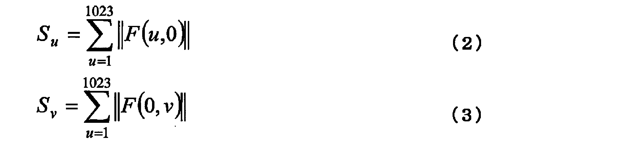
式(2)及び式(3)において、F(u,v)は式(4)で定義される。

式(4)において、f(x,y)は、前記2次元画像の座標(x,y)の階調を表す。
上述の通り、αと焼付硬化性とは図7に示す関係性を有し、そしてαと焼付硬化後の曲げ性とは図8に示す関係性を有する。本発明の一実施形態による冷延鋼板は組織から求めたαが1.20以下であれば、図7及び8に示す通り、焼付硬化量BHが100MP以上となり、そして焼付硬化後の最小曲げ半径と板厚との比であるR/tが1.0未満となる。したがって、本発明の一実施形態による冷延鋼板は優れた焼付硬化性及び耐衝撃性を有する。αは、好ましくは1.10以下であり、さらに好ましくは1.05以下である。αの下限値は特に規定しないが、一般的には0.90以上である。
以上のことから、本発明の一実施形態による冷延鋼板は、塗装焼付硬化性能に優れ、かつ優れた耐衝撃性を有する。このため、本実施形態の冷延鋼板はプレス加工されて使用される自動車等の構造部材に用いることが好ましい。
(機械特性)
本実施形態による冷延鋼板は、好ましくは780MPa以上の引張強度を有し、より好ましくは800MPa以上、さらに好ましくは900MPa以上の引張強度を有する。
本実施形態による冷延鋼板は、好ましくは780MPa以上の引張強度を有し、より好ましくは800MPa以上、さらに好ましくは900MPa以上の引張強度を有する。
本実施形態による冷延鋼板は、好ましくは100MP以上の焼付硬化量を有し、より好ましくは120MPa以上、さらに好ましくは150MPa以上の焼付硬化量を有する。
本実施形態による冷延鋼板は、好ましくは10%以上の破断伸びを有し、より好ましくは12%以上の破断伸びを有する。本実施形態による冷延鋼板は、優れた焼付硬化後の曲げ性を有し、好ましくは1.0未満の最小曲げ半径/板厚比を有し、より好ましくは0.5以下の最小曲げ半径/板厚比を有する。
(III)製造方法
次に、本発明の実施形態に係る冷延鋼板の好ましい製造方法について説明する。
次に、本発明の実施形態に係る冷延鋼板の好ましい製造方法について説明する。
以下の説明は、本発明の実施形態に係る冷延鋼板を製造するための特徴的な方法の例示
を意図するものであって、当該冷延鋼板を以下に説明するような製造方法によって製造されるものに限定することを意図するものではない。
を意図するものであって、当該冷延鋼板を以下に説明するような製造方法によって製造されるものに限定することを意図するものではない。
上記製造方法は、上で説明した化学成分組成を有する溶鋼を鋳造してスラブを形成する工程、
前記スラブを1050℃以上1250℃以下の温度域で粗圧延する粗圧延工程であって、前記粗圧延が1パス当たりの圧下率が30%以下のリバース圧延によって行われ、前記リバース圧延が、下記(i)及び(ii):
(i)第1パスの圧下率が20%以上30%以下、第2パスの圧下率が15%以下の1往復、及び
(ii)第3パスの圧下率が15%以下、第4パスの圧下率が20%以上30%以下の1往復
の合計2往復を1セットとする圧延を3セット以上含み、1往復する際の2パス間の圧下率差が5%以上である粗圧延工程、
前記粗圧延工程の後5秒未満で開始され、粗圧延された鋼板を850℃以上1050℃以下の温度域で仕上げ圧延する仕上げ圧延工程であって、前記仕上げ圧延が4つ以上の連続する圧延スタンドで行われ、第一スタンドの圧下率が15%未満であり、仕上げ圧延された鋼板が200℃以下の温度域で巻き取られる仕上げ圧延工程、
得られた熱延鋼板を30%以下の圧下率で冷間圧延する冷間圧延工程、
得られた冷延鋼板をAc1以上1000℃以下の温度域で10秒以上1000秒以下保持し、次いで10℃/秒以上200℃/秒以下の平均冷却速度で200℃以下まで冷却する焼鈍工程、並びに
得られた鋼板を200℃以上350℃以下の温度域で100秒以上保持する焼戻し工程を含むことを特徴としている。以下、各工程について説明する。
前記スラブを1050℃以上1250℃以下の温度域で粗圧延する粗圧延工程であって、前記粗圧延が1パス当たりの圧下率が30%以下のリバース圧延によって行われ、前記リバース圧延が、下記(i)及び(ii):
(i)第1パスの圧下率が20%以上30%以下、第2パスの圧下率が15%以下の1往復、及び
(ii)第3パスの圧下率が15%以下、第4パスの圧下率が20%以上30%以下の1往復
の合計2往復を1セットとする圧延を3セット以上含み、1往復する際の2パス間の圧下率差が5%以上である粗圧延工程、
前記粗圧延工程の後5秒未満で開始され、粗圧延された鋼板を850℃以上1050℃以下の温度域で仕上げ圧延する仕上げ圧延工程であって、前記仕上げ圧延が4つ以上の連続する圧延スタンドで行われ、第一スタンドの圧下率が15%未満であり、仕上げ圧延された鋼板が200℃以下の温度域で巻き取られる仕上げ圧延工程、
得られた熱延鋼板を30%以下の圧下率で冷間圧延する冷間圧延工程、
得られた冷延鋼板をAc1以上1000℃以下の温度域で10秒以上1000秒以下保持し、次いで10℃/秒以上200℃/秒以下の平均冷却速度で200℃以下まで冷却する焼鈍工程、並びに
得られた鋼板を200℃以上350℃以下の温度域で100秒以上保持する焼戻し工程を含むことを特徴としている。以下、各工程について説明する。
(スラブの形成工程)
スラブは、例えば、転炉又は電気炉等を用いて、上で説明した本発明の実施形態に係る鋼板の化学組成を有する溶鋼を溶製し、連続鋳造法により製造することができる。連続鋳造法に代えて、造塊法、薄スラブ鋳造法等を採用してもよい。
スラブは、例えば、転炉又は電気炉等を用いて、上で説明した本発明の実施形態に係る鋼板の化学組成を有する溶鋼を溶製し、連続鋳造法により製造することができる。連続鋳造法に代えて、造塊法、薄スラブ鋳造法等を採用してもよい。
(粗圧延工程)
該スラブは以下の粗圧延工程を施す前に、1000℃以上1300℃以下の温度域に加熱してもよい。加熱した後の保持時間は特に規定しないが、スラブ中心部まで所定の温度にするために、30分間以上とすることが好ましい。また、過度のスケールロスを抑制するために10時間以下とすることが好ましく、5時間以下とすることがさらに好ましい。なお、直送圧延又は直接圧延を行う場合であって、鋳造後のスラブの温度が1050℃以上1250℃以下であれば、加熱と保持を施さずにそのまま以下の粗圧延工程に供してもよい。
該スラブは以下の粗圧延工程を施す前に、1000℃以上1300℃以下の温度域に加熱してもよい。加熱した後の保持時間は特に規定しないが、スラブ中心部まで所定の温度にするために、30分間以上とすることが好ましい。また、過度のスケールロスを抑制するために10時間以下とすることが好ましく、5時間以下とすることがさらに好ましい。なお、直送圧延又は直接圧延を行う場合であって、鋳造後のスラブの温度が1050℃以上1250℃以下であれば、加熱と保持を施さずにそのまま以下の粗圧延工程に供してもよい。
リバース圧延のみを用いた粗圧延を施すことによって、スラブ中のMn偏析部を一方向に引き伸ばされた板状にすることなく、複雑形状に制御することが可能となる。したがって、後の工程において、バンド状組織の形成を抑制するとともに、フェライトが複雑に入り組んだ組織が得られる。その結果として、最終的に、不均質度αが1.20以下に制御され、フェライトが焼戻しマルテンサイトにより微細かつ均質に分割された架橋構造を有する複合組織を含む冷延鋼板を得ることができる。なお、従来の複合組織を含む冷延鋼板は、以下に説明するような1往復における圧下率差をつけたリバース圧延が施されていないため、不均質度αを1.20以下にすることができない。
上記のMn偏析部の複雑形状化についてより詳しく説明すると、まず、粗圧延を開始する前のスラブにおいては、Mn等の合金元素が濃化した部分が、スラブの両方の表面から内部に向かって櫛状の形態でほぼ垂直に成長して複数並んだ状態になっている。一方、粗圧延では、圧延の1パスごとに、スラブの表面は圧延の進行方向に伸ばされることとなる。圧延の進行方向とは、圧延ロールに対してスラブが進行していく方向である。このようにスラブの表面が圧延の進行方向に伸ばされることにより、スラブの表面から内部に向かって成長しているMn偏析部は、圧延の1パスごとにスラブの進行方向に傾斜した状態にされる。
粗圧延の各パスにおけるスラブの進行方向が常に同じ方向であるいわゆる一方向圧延の場合、Mn偏析部は、ほほ真っ直ぐな状態を保ったまま、パスごとに同じ方向に向かって徐々に傾斜が強くなっていく。また、粗圧延の終了時には、Mn偏析部は、ほほ真っ直ぐな状態を保ったまま、スラブの表面に対してほぼ平行な姿勢となり、扁平なミクロ偏析が形成されてしまう。
一方、粗圧延の各パスにおけるスラブの進行方向が交互に反対の方向となるリバース圧延の場合は、直前のパスで傾斜させられたMn偏析部が、次のパスでは逆の方向に傾斜させられることとなり、その結果、Mn偏析部は折れ曲がった形状となる。このため、リバース圧延においては、交互に反対の方向となる各パスが繰り返し行われることにより、Mn偏析部が複雑に折れ曲がった形状となる。
粗圧延の温度が、1050℃未満では、後の仕上げ圧延工程において850℃以上の温度で圧延を完了することが難しく、鋼板の形状が不良となる。また、1250℃超ではスラブ予加熱時のスケールロスが増大する上、スラブ割れ発生の要因になることから、粗圧延温度は1050℃以上1250℃以下とする。粗圧延温度の下限値は1100℃であることが好ましい。粗圧延温度の上限値は1200℃であることが好ましい。
粗圧延における1パスの圧下率が30%超であると、圧延時のせん断応力が大きくなるため、Mn偏析部がバンド状に分布しやすくなり、複雑形状に分布させることが出来ない。そのため、粗圧延における1パスの圧下率は30%以下とする。圧下率が小さい程、圧延時のせん断ひずみが小さくなり、バンド組織の形成を抑制することから、圧下率の下限は特に定めないが、生産性の観点から、10%以上であることが好ましく、15%であることがより好ましい。
Mn偏析部を複雑形状、より具体的には網目形状にし、その結果として焼戻しマルテンサイトとフェライトの架橋構造を得るためには、圧延時のせん断応力を変えるため,圧下率を各パスにおいて制御しなければならない。Mn偏析部をバンド状に分布しにくくするために、往復で異なる圧下率のリバース圧延を2回繰り返すことが好ましい。その際、圧延温度が高温である第1パスで進行方向と同じ方向に大圧下することでバンド状に分布させたあと、圧延温度が低温である第4パスで進行方向と反対方向に大圧下することでMn偏析部を複雑形状に分布させるために、第1パスと第4パスの圧下率を他のパスの圧下率より高くすることが好ましい。すなわち,圧延は下記(i)及び(ii)の合計2往復を1セットとする圧延を3セット以上施す。
(i)第1パスの圧下率が20%以上30%以下、第2パスの圧下率が15%以下の1往復、及び
(ii)第3パスの圧下率が15%以下、第4パスの圧下率が20%以上30%以下の1往復
ただし、上記の圧延を6セット以上施すと十分な仕上げ圧延温度を確保することが難しくなるので、5セット以下とすることが好ましい。
(i)第1パスの圧下率が20%以上30%以下、第2パスの圧下率が15%以下の1往復、及び
(ii)第3パスの圧下率が15%以下、第4パスの圧下率が20%以上30%以下の1往復
ただし、上記の圧延を6セット以上施すと十分な仕上げ圧延温度を確保することが難しくなるので、5セット以下とすることが好ましい。
また、進行方向が互いに反対の方向となる各パスは、同じ回数ずつ行われること、すなわち合計のパス回数を偶数回とすることが望ましい。しかしながら、一般の粗圧延ラインでは、粗圧延の入側と出側はロールを挟んで反対側に位置する。このため、粗圧延の入側から出側に向かう方向のパス(圧延)が一回多くなる。そうすると、最後のパス(圧延)でMn偏析部が板状となり、Mnの網目状分布が形成されにくくなる。このような熱間圧延ラインで粗圧延をする場合には、粗圧延板を最後に入側から出側に送る際の圧下率を5%以下にすることが好ましく、ロール間を開けて圧延を省略することがより好ましい。
後述するように、再結晶組織を微細化するためには、仕上げ圧延におけるタンデムの多段圧延が有効であるが、タンデム圧延によって、扁平なミクロ偏析が形成されやすくなる。タンデムの多段圧延を利用するためには、上記リバース圧延の1往復における圧下率差を大きくし、その後のタンデム圧延で形成されるミクロ偏析を制御しなければならない。その効果はリバース圧延の1往復における圧下率差が5%以上となると顕著になる。そのため、リバース圧延の1往復における圧下率差は5%以上とすることが好ましく、10%以上とすることがより好ましい。
粗圧延におけるリバース圧延によって生成したMnの網目構造を維持するために、オーステナイト粒界移動を抑制する必要があるため、粗圧延から仕上げ圧延までの保持時間は5秒未満とすることが好ましく、3秒以下とすることがより好ましい。
(仕上げ圧延工程)
粗圧延におけるリバース圧延の後、仕上げ圧延におけるタンデム圧延の圧下率を大きくすることによって、デンドライト二次アームに起因するMn偏析帯の間隔を狭小化するために、仕上げ圧延は4つ以上の連続する圧延スタンドで行われることが好ましい。850℃未満で仕上げ圧延を完了すると、再結晶が十分に起きず、圧延方向に延伸した組織となり、後の工程において延伸組織に起因した板状組織が形成する。したがって、仕上げ圧延完了温度は850℃以上とし、900℃以上とすることが好ましい。一方、仕上げ圧延温度が1050℃を超えると、オーステナイトの微細な再結晶粒が生成しにくくなり、粒界のMn偏析が困難となり、Mn偏析帯が扁平となりやすくなる。そのため、仕上げ圧延温度は1050℃以下とする。必要に応じて、粗圧延された鋼板を粗圧延工程の後でかつ仕上げ圧延工程の前に再加熱してもよい。さらに、仕上げ圧延の第一スタンドの圧下率を15%未満とし、再結晶粒の多量生成を抑制することで、粗圧延工程で形成したMnの網目構造を維持しやすくなる。このように、粗圧延工程だけでなく、仕上げ圧延工程を限定することによって、扁平なMnのミクロ偏析を抑制できる。また、仕上げ圧延の第一スタンドの圧下率は10%以下であることが好ましい。
粗圧延におけるリバース圧延の後、仕上げ圧延におけるタンデム圧延の圧下率を大きくすることによって、デンドライト二次アームに起因するMn偏析帯の間隔を狭小化するために、仕上げ圧延は4つ以上の連続する圧延スタンドで行われることが好ましい。850℃未満で仕上げ圧延を完了すると、再結晶が十分に起きず、圧延方向に延伸した組織となり、後の工程において延伸組織に起因した板状組織が形成する。したがって、仕上げ圧延完了温度は850℃以上とし、900℃以上とすることが好ましい。一方、仕上げ圧延温度が1050℃を超えると、オーステナイトの微細な再結晶粒が生成しにくくなり、粒界のMn偏析が困難となり、Mn偏析帯が扁平となりやすくなる。そのため、仕上げ圧延温度は1050℃以下とする。必要に応じて、粗圧延された鋼板を粗圧延工程の後でかつ仕上げ圧延工程の前に再加熱してもよい。さらに、仕上げ圧延の第一スタンドの圧下率を15%未満とし、再結晶粒の多量生成を抑制することで、粗圧延工程で形成したMnの網目構造を維持しやすくなる。このように、粗圧延工程だけでなく、仕上げ圧延工程を限定することによって、扁平なMnのミクロ偏析を抑制できる。また、仕上げ圧延の第一スタンドの圧下率は10%以下であることが好ましい。
巻取温度は200℃以下が好ましい。巻取温度を200℃以下とすることでオーステナイトが冷却中に硬質なマルテンサイトに変態し、その際の変態ひずみ導入によりマルテンサイト近傍の軟質なフェライトに多量のひずみが導入され、次の焼鈍による再結晶フェライトの微細化、均質化に寄与する。巻取温度が200℃超では、マルテンサイトの生成が抑制されるため、上記効果が得られず、不均質度αが本発明で規定される条件を満足しない。そのため巻取温度は200℃以下であり、好ましくは100℃以下であり、さらに好ましくは50℃以下である。巻取温度を200℃以下とすることで得られた組織に冷間圧延を施すことで、硬質なマルテンサイト近傍のフェライトに応力が集中し、多量のひずみが導入される。この状態で焼鈍することで、再結晶フェライト核が多数生成し、均質微細な組織が得られる。また逆変態γもマルテンサイトラス間から微細に生成する。前記粗圧延工程で形成したMnの網目構造に加え、この両方の効果によりマルテンサイトがフェライトを細かく分割し、架橋構造をとることで本発明で規定する組織が得られる。曲げ性は加工効果能と極限変形能の双方が優れている必要があるが、マルテンサイトがフェライトを細かく分割し、架橋構造をとることでフェライトの加工硬化能が向上し、さらに均質組織のため極限変形能にも優れる。
一方で、200℃超の高温巻取りでは硬質マルテンサイトは生成しないため、低温巻取りに比べて冷間圧延後のフェライトへのひずみ導入量が少なくなり、目的の組織及び特性は得られない。
(冷間圧延工程)
上記粗圧延及び仕上げ圧延工程で造り込まれたマルテンサイトとフェライトの架橋構造を維持する観点から、冷間圧延の圧下率を低減することが重要である。冷間圧延の圧下率を低く抑えることで、マルテンサイトとフェライトの架橋構造を焼鈍後も維持することができる。この効果を得るために、冷間圧延の圧下率の上限値は、30%であり、好ましくは20%である。冷間圧延の圧下率が30%を超えると、マルテンサイトとフェライトの架橋構造が板厚方向に押し潰されてしまい、不均質度αが本発明で規定される条件を満足しない。組織を均質化及び/又は微細化する観点から、冷間圧延の下限値は、5%であり、好ましくは7%であり、より好ましくは10%である。冷間圧延の圧下率を30%以下とすることは、本発明で規定する不均質度αの条件を満足するための重要な要件である。
上記粗圧延及び仕上げ圧延工程で造り込まれたマルテンサイトとフェライトの架橋構造を維持する観点から、冷間圧延の圧下率を低減することが重要である。冷間圧延の圧下率を低く抑えることで、マルテンサイトとフェライトの架橋構造を焼鈍後も維持することができる。この効果を得るために、冷間圧延の圧下率の上限値は、30%であり、好ましくは20%である。冷間圧延の圧下率が30%を超えると、マルテンサイトとフェライトの架橋構造が板厚方向に押し潰されてしまい、不均質度αが本発明で規定される条件を満足しない。組織を均質化及び/又は微細化する観点から、冷間圧延の下限値は、5%であり、好ましくは7%であり、より好ましくは10%である。冷間圧延の圧下率を30%以下とすることは、本発明で規定する不均質度αの条件を満足するための重要な要件である。
(焼鈍工程)
上記冷間圧延工程を経て得られた鋼板に、焼鈍処理を施す。焼鈍温度での加熱は、Ac1以上1000℃以下の温度域で、10秒以上1000秒以下加熱保持とする。この温度範囲は、フェライトと硬質組織の面積率を決めるものである。焼鈍処理の温度範囲の上限値は870℃であることが好ましく、850℃であることがより好ましい。焼鈍時間は、冷間加工されたフェライトを十分に再結晶させること、及びフェライトと硬質組織の面積率を制御しやすくするために、10秒以上とする。また、焼鈍時間が1000秒を超えると生産性が悪くなる。従って、焼鈍時間は10秒以上1000秒以下とする。焼鈍時間の上限値は300秒であることが好ましい。焼鈍時間の下限値は200秒であることが好ましい。
上記冷間圧延工程を経て得られた鋼板に、焼鈍処理を施す。焼鈍温度での加熱は、Ac1以上1000℃以下の温度域で、10秒以上1000秒以下加熱保持とする。この温度範囲は、フェライトと硬質組織の面積率を決めるものである。焼鈍処理の温度範囲の上限値は870℃であることが好ましく、850℃であることがより好ましい。焼鈍時間は、冷間加工されたフェライトを十分に再結晶させること、及びフェライトと硬質組織の面積率を制御しやすくするために、10秒以上とする。また、焼鈍時間が1000秒を超えると生産性が悪くなる。従って、焼鈍時間は10秒以上1000秒以下とする。焼鈍時間の上限値は300秒であることが好ましい。焼鈍時間の下限値は200秒であることが好ましい。
Ac1点は次の式により計算する。
Ac1=751-16×C+35×Si―28×Mn-16×Ni+13×Cr-6×Cu+3×Mo
上記式において、C、Si、Mn、Ni、Cr、Cu及びMoは各元素の含有量(質量%)であり、含有しない元素については0質量%を代入する。
Ac1=751-16×C+35×Si―28×Mn-16×Ni+13×Cr-6×Cu+3×Mo
上記式において、C、Si、Mn、Ni、Cr、Cu及びMoは各元素の含有量(質量%)であり、含有しない元素については0質量%を代入する。
焼鈍温度保持後、冷却は10℃/秒以上200℃/秒以下の冷却速度で行う。組織を凍結し、マルテンサイト変態を効率的に引き起こすためには、冷却速度は速いほうがよい。ただし、冷却速度が10℃/秒未満ではマルテンサイトが十分に生成せず、所望の組織に制御できない。一方で、冷却速度が200℃/秒を超えても、その効果は飽和するため、焼鈍後の冷却速度は、10℃/秒以上200℃/秒以下とする。焼鈍後の冷却速度の上限値は50℃/秒であることが好ましい。焼鈍後の冷却速度の下限値は10℃/秒であることが好ましい。上記冷却速度は、平均冷却速度とは異なり、冷却中の何れの温度域においても10℃/秒を下回らないことを意味する。冷却停止温度は200℃以下とする。これは、焼鈍温度保持後にマルテンサイトを生成させるためである。このとき、200℃以上500℃以下で冷却を停止し、10秒以上1000秒以下保持する工程を入れてもよい。冷却停止温度は55℃以下であることが好ましく、45℃以下であることがより好ましい。
(焼戻し工程)
得られた鋼板は、焼戻し工程において、加熱により200℃以上350℃以下の温度域で保持される。保持温度は好ましくは250℃以上300℃以下とする。保持温度が200℃未満であった場合、マルテンサイトが焼戻されないため、予ひずみ分配が変化しない。350℃超であった場合、粗大な炭化物の析出により全体の固溶炭素量が減ってしまうため、焼付硬化性が低下する。また、保持温度がフェライトの再結晶温度よりも高くなると、母相中に生成した再結晶フェライトによりフェライトと母相の界面の分布が変化し、その結果としてマルテンサイトとフェライトの架橋構造が分断又は崩壊する場合がある。一方、硬質組織全体を焼戻すために、保持時間は100秒以上とする。その後、生産性の観点から、2℃/秒以上の平均冷却速度で100℃以下まで冷却する。冷却停止温度は50℃以下であることが好ましく、45℃以下であることがより好ましい。
得られた鋼板は、焼戻し工程において、加熱により200℃以上350℃以下の温度域で保持される。保持温度は好ましくは250℃以上300℃以下とする。保持温度が200℃未満であった場合、マルテンサイトが焼戻されないため、予ひずみ分配が変化しない。350℃超であった場合、粗大な炭化物の析出により全体の固溶炭素量が減ってしまうため、焼付硬化性が低下する。また、保持温度がフェライトの再結晶温度よりも高くなると、母相中に生成した再結晶フェライトによりフェライトと母相の界面の分布が変化し、その結果としてマルテンサイトとフェライトの架橋構造が分断又は崩壊する場合がある。一方、硬質組織全体を焼戻すために、保持時間は100秒以上とする。その後、生産性の観点から、2℃/秒以上の平均冷却速度で100℃以下まで冷却する。冷却停止温度は50℃以下であることが好ましく、45℃以下であることがより好ましい。
(スキンパス圧延工程)
以上の方法で製造された冷延鋼板に、任意選択で最終のスキンパス圧延(調質圧延)を施してもよい。スキンパス圧延を施すことにより、予ひずみがなくとも、鋼板にひずみが入るので、焼付硬化性を高めることができる。ひずみを鋼板に均一に導入するために、圧下率は0.1%以上とし、板厚制御が困難になるため、0.5%を上限とすることが好ましい。
以上の方法で製造された冷延鋼板に、任意選択で最終のスキンパス圧延(調質圧延)を施してもよい。スキンパス圧延を施すことにより、予ひずみがなくとも、鋼板にひずみが入るので、焼付硬化性を高めることができる。ひずみを鋼板に均一に導入するために、圧下率は0.1%以上とし、板厚制御が困難になるため、0.5%を上限とすることが好ましい。
このようにして、本発明の実施形態に係る冷延鋼板を製造することができる。
上記実施形態は、何れも本発明を実施するにあたっての具体化の例を示したものに過ぎず、これらによって本発明の技術的範囲が限定的に解釈されてはならないものである。すなわち、本発明はその技術思想、又はその主要な特徴から逸脱することなく、様々な形で実施することができる。
次に、本発明の実施例について説明する。実施例での条件は、本発明の実施可能性及び効果を確認するために採用した一条件例であり、本発明は、この一条件例に限定されるものではない。本発明は、本発明の要旨を逸脱せず、本発明の目的を達成する限りにおいて、種々の条件を採用し得るものである。
表1に示す化学組成を有するスラブを製造し、スラブを1300℃に1時間加熱した後、表2に示す条件にて粗圧延及び仕上げ圧延を行い、次いで鋼板を巻き取り、表2に示す巻き取り温度で1時間保持し、板厚2mmの熱延鋼板を得た。その後、熱延鋼板の酸洗を行い、表2に示す圧下率で冷間圧延を行って表2に示す板厚を有する冷延鋼板を得た。続いて、表2に示す条件下で焼鈍、焼戻し及び/又はスキンパス圧延を行った。
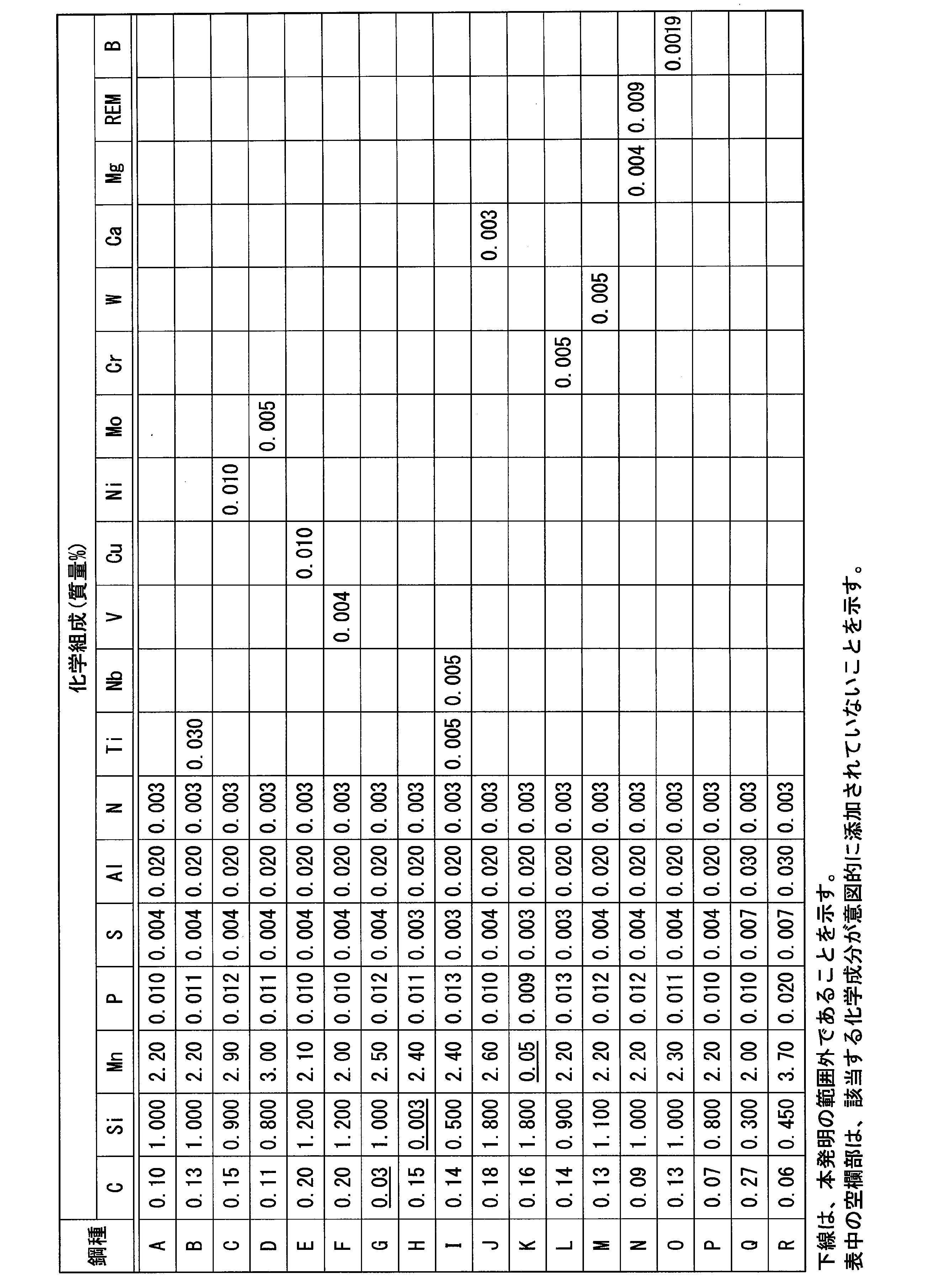

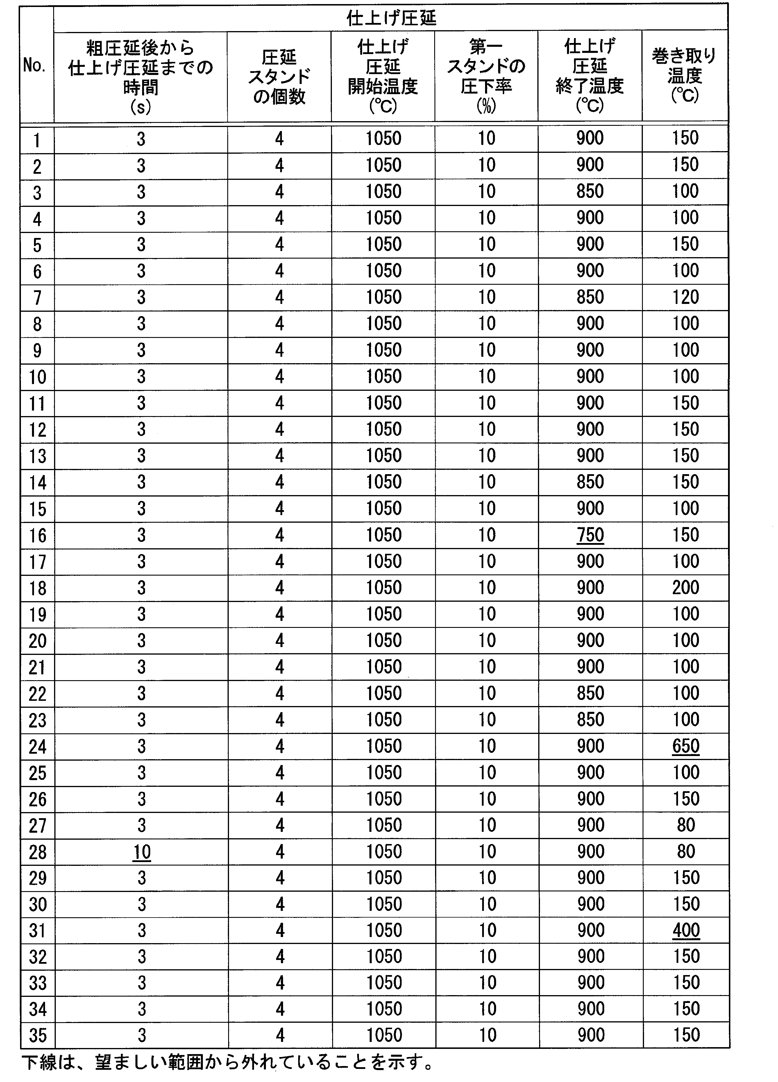

得られた冷延鋼板の鋼組織を観察した。鋼組織の観察では、上記の方法により、フェライトの面積率、焼戻しマルテンサイトの面積率、及び不均質度αを求めた。
特に、フェライトの面積率及び焼戻しマルテンサイトの面積率は以下のようにして決定した。まず、鋼板の圧延方向に垂直な板厚断面を観察面として試料を採取し、観察面を研磨し、当該鋼板の厚さの1/4位置の組織を5000倍の倍率でSEM-EBSDで観察し、それを100μm×100μmの視野で画像解析してフェライトの面積率を測定し、任意の5視野におけるこれらの測定値の平均をフェライトの面積率として決定した。
また、鋼板の表面からの深さが3t/8からt/2までの領域のSEMの2次電子像を撮影し(倍率1500倍)、得られた画像データの白色部分が硬質組織であり、黒色部分がフェライトであることから、当該画像データに基づいて硬質組織の面積率を決定した。硬質組織は、上記SEMの2次電子画像を5000倍又は10000倍で観察した際に、当該硬質組織内に微細炭化物が析出している場合に焼戻しマルテンサイトと判断した。これらの結果を表3に示す。
更に、得られた冷延鋼板の引張強度TS、破断伸びEL、焼付硬化量BH、及び最小曲げ半径Rを測定した。引張強度TS、破断伸びEL、及び焼付硬化量BHの測定では、圧延方向に直角な方向を長手方向とするJIS5号引張試験片を採取し、JIS Z 2241に準拠して引張試験を行った。BHは2%予ひずみを付加後、170℃で20分間熱処理した試験片を再引張したときの応力から、2%予ひずみ付加時の応力を差し引いた値である。自動車車体の軽量化の要求を満たすためには引張強度は780MPa以上である。また、成形しやすいために、破断伸びは10%以上であることが好ましい。また、BHについては、100MPa未満では成形しにくく且つ成形後の強度が低くなるため、優れた焼付硬化性を有するためには、100MPa以上であることが好ましい。
塗装焼付硬化処理後の曲げ性を評価する指標としては、最小曲げ半径と板厚との比であるR/tが用いられる。最小曲げ半径Rの測定はJIS Z 2248に規定されるVブロック法(押金具の先端角:90°、先端半径R:0.5mmから0.5mmピッチで変更)を用いて試験片幅30mmとして実施した。最小曲げ半径と板厚との比であるR/tが1.0以上であると、塗装焼付硬化処理後の試験片は衝突時における蛇腹状変形の際に生じる曲げ応力ですぐ破断してしまう場合がある。すなわち、部品としての衝突性能が悪い。従って、BH測定後の最小曲げ半径と板厚との比であるR/tは1.0未満が好ましい。

[評価結果]
表3に示すように、実施例1、3、6、7、10、15、17、20、22、23、2527、33、34及び35では、優れたTS、BH及びR/tを得ることができた。いずれもTSが780MPa以上、BHが100MPa以上、R/tが1.0未満となり、高強度で且つ焼付硬化性に優れ、焼付硬化後の曲げ性にも優れることが示された。
表3に示すように、実施例1、3、6、7、10、15、17、20、22、23、2527、33、34及び35では、優れたTS、BH及びR/tを得ることができた。いずれもTSが780MPa以上、BHが100MPa以上、R/tが1.0未満となり、高強度で且つ焼付硬化性に優れ、焼付硬化後の曲げ性にも優れることが示された。
一方、比較例2では、焼戻し保持時間が短すぎたために焼戻しマルテンサイトが所望の面積率にならず、鋼のBHが低くR/tが高かった。比較例4では、冷間圧延の圧下率が高かったためにマルテンサイトとフェライトの架橋構造を維持できず、結果として不均質度αが大きくなり、BHが低くR/tが高かった。
比較例5では、焼戻し保持温度が低かったために焼戻しマルテンサイトが所望の面積率にならず、鋼のBHが低くR/tが高かった。比較例8では、焼鈍温度が低かったためにフェライトの面積率が過度に高くかつ焼戻しマルテンサイトの面積率が過度に低くなり、鋼のTS及びBHが低かった。
比較例9では、焼鈍時間が短かったために、結果として焼戻しマルテンサイトが所望の面積率にならず、鋼のTS及びBHが低くR/tが高かった。比較例11では、焼鈍後の冷却速度が遅かったためにマルテンサイトが十分に生成しなかった。そのため、フェライトの面積率が過度に高くかつ焼戻しマルテンサイトの面積率が過度に低くなり、TS及びBHが低かった。比較例12では、焼戻し保持温度が高かったために粗大な炭化物が析出してしまい、また再結晶フェライトの生成に起因してマルテンサイトとフェライトの架橋構造を維持できず、結果として不均質度αが大きくなり、BHが低くR/tが高かった。
比較例13では、C含有量が低かったためにフェライトと焼戻しマルテンサイトが所望の面積率にならず、鋼のTS及びBHが低かった。比較例14では、Si含有量が低かったために粗大な炭化物が析出してしまい、BHが低くR/tが高かった。比較例16では、仕上げ圧延の完了温度が低かったために不均質度αが大きくなり、BHが低くR/tが高かった。比較例18では、Mn含有量が低かったために焼戻しマルテンサイトが所望の面積率にならず、TS及びBHが低くR/tが高かった。
比較例19では、粗圧延の1往復内に含まれる2パス間の圧下率差が低かったために不均質度αが大きくなり、BHが低くR/tが高かった。比較例21では、粗圧延の圧下率が高かったために不均質度αが大きくなり、BHが低くR/tが高かった。比較例24では、巻取温度が高かったためにマルテンサイトの生成が抑制され、結果として不均質度αが大きくなり、BHが低くR/tが高かった。比較例26では、粗圧延の回数が少なかったために焼戻しマルテンサイトとフェライトの架橋構造を得ることができず、不均質度αが大きくなり、BHが低くR/tが高かった。比較例28では、粗圧延から仕上げ圧延までの保持時間が長かったために焼戻しマルテンサイトとフェライトの架橋構造を得ることができず、不均質度αが大きくなり、BHが低くR/tが高かった。
比較例29では、粗圧延の第1パスの圧下率が低くかつ粗圧延の第2パスの圧下率が高かったために焼戻しマルテンサイトとフェライトの架橋構造を得ることができず、不均質度αが大きくなり、BHが低くR/tが高かった。比較例30では、粗圧延の第3パスの圧下率が高くかつ粗圧延の第4パスの圧下率が低かったために焼戻しマルテンサイトとフェライトの架橋構造を得ることができず、不均質度αが大きくなり、BHが低くR/tが高かった。比較例31では、巻取温度が高かったために熱延鋼板におけるマルテンサイトの生成が抑制されるため、フェライトへ導入されるひずみ量が少なく、結果として不均質度αが大きくなり、BHが低くR/tが高かった。比較例32では、冷間圧延の圧下率が高かったためにマルテンサイトとフェライトの架橋構造を維持できず、結果として不均質度αが大きくなり、BHが低くR/tが高かった。
比較例5では、焼戻し保持温度が低かったために焼戻しマルテンサイトが所望の面積率にならず、鋼のBHが低くR/tが高かった。比較例8では、焼鈍温度が低かったためにフェライトの面積率が過度に高くかつ焼戻しマルテンサイトの面積率が過度に低くなり、鋼のTS及びBHが低かった。
比較例9では、焼鈍時間が短かったために、結果として焼戻しマルテンサイトが所望の面積率にならず、鋼のTS及びBHが低くR/tが高かった。比較例11では、焼鈍後の冷却速度が遅かったためにマルテンサイトが十分に生成しなかった。そのため、フェライトの面積率が過度に高くかつ焼戻しマルテンサイトの面積率が過度に低くなり、TS及びBHが低かった。比較例12では、焼戻し保持温度が高かったために粗大な炭化物が析出してしまい、また再結晶フェライトの生成に起因してマルテンサイトとフェライトの架橋構造を維持できず、結果として不均質度αが大きくなり、BHが低くR/tが高かった。
比較例13では、C含有量が低かったためにフェライトと焼戻しマルテンサイトが所望の面積率にならず、鋼のTS及びBHが低かった。比較例14では、Si含有量が低かったために粗大な炭化物が析出してしまい、BHが低くR/tが高かった。比較例16では、仕上げ圧延の完了温度が低かったために不均質度αが大きくなり、BHが低くR/tが高かった。比較例18では、Mn含有量が低かったために焼戻しマルテンサイトが所望の面積率にならず、TS及びBHが低くR/tが高かった。
比較例19では、粗圧延の1往復内に含まれる2パス間の圧下率差が低かったために不均質度αが大きくなり、BHが低くR/tが高かった。比較例21では、粗圧延の圧下率が高かったために不均質度αが大きくなり、BHが低くR/tが高かった。比較例24では、巻取温度が高かったためにマルテンサイトの生成が抑制され、結果として不均質度αが大きくなり、BHが低くR/tが高かった。比較例26では、粗圧延の回数が少なかったために焼戻しマルテンサイトとフェライトの架橋構造を得ることができず、不均質度αが大きくなり、BHが低くR/tが高かった。比較例28では、粗圧延から仕上げ圧延までの保持時間が長かったために焼戻しマルテンサイトとフェライトの架橋構造を得ることができず、不均質度αが大きくなり、BHが低くR/tが高かった。
比較例29では、粗圧延の第1パスの圧下率が低くかつ粗圧延の第2パスの圧下率が高かったために焼戻しマルテンサイトとフェライトの架橋構造を得ることができず、不均質度αが大きくなり、BHが低くR/tが高かった。比較例30では、粗圧延の第3パスの圧下率が高くかつ粗圧延の第4パスの圧下率が低かったために焼戻しマルテンサイトとフェライトの架橋構造を得ることができず、不均質度αが大きくなり、BHが低くR/tが高かった。比較例31では、巻取温度が高かったために熱延鋼板におけるマルテンサイトの生成が抑制されるため、フェライトへ導入されるひずみ量が少なく、結果として不均質度αが大きくなり、BHが低くR/tが高かった。比較例32では、冷間圧延の圧下率が高かったためにマルテンサイトとフェライトの架橋構造を維持できず、結果として不均質度αが大きくなり、BHが低くR/tが高かった。
本発明の冷延鋼板は、特に、自動車産業分野において自動車の構造部材として利用することができる。
Claims (3)
- 質量%で、
C:0.05~0.30%、
Si:0.200~2.000%、
Mn:2.00~4.00%、
P:0.100%以下、
S:0.010%以下、
Al:0.001~2.000%、
N:0.010%以下
Ti:0~0.100%、
Nb:0~0.100%、
V:0~0.100%、
Cu:0~1.000%、
Ni:0~1.000%、
Mo:0~1.000%、
Cr:0~1.000%、
W:0~0.005%、
Ca:0~0.005%、
Mg:0~0.005%、
REM:0~0.010%、
B:0~0.0030%、
を含有し、残部がFe及び不純物からなり、
面積率で、20%以上70%以下のフェライト、及び30%以上の焼戻しマルテンサイトを含有し、
フェライト及び焼戻しマルテンサイトの合計が90%以上であり、
前記冷延鋼板の板幅の1/8から7/8までの位置の鋼板の板幅方向に垂直な板厚断面において、表面から板厚の1/4から3/8までの位置の組織を2000倍の倍率で撮影して得られた30μm×30μmのミクロ組織画像を、板厚方向をx軸としかつ圧延方向をy軸とするxy座標系に配置し、次いで前記ミクロ組織画像をx軸方向に1024個、y軸方向に1024個分割して1024×1024個の分割領域を形成し、前記分割領域のそれぞれにおける値を組織がフェライトである場合に「1」、そうでない場合に「0」として2階調化して2次元画像を作成し、前記2次元画像に対して、式(1)で定義される不均質度αが1.20以下である、冷延鋼板。


- 更に、質量%で、
Ti:0.003%~0.100%、
Nb:0.003%~0.100%、
V:0.003%~0.100%
の1種又は2種以上を合計で0.100%以下含有する、請求項1に記載の冷延鋼板。 - 前記ミクロ組織画像が、前記冷延鋼板の板幅の中央位置の鋼板の板幅方向に垂直な板厚断面において、表面から板厚の1/4から3/8までの位置の組織を2000倍の倍率で撮影して得られた30μm×30μmのミクロ組織画像である、請求項1又は請求項2のいずれか一項に記載の冷延鋼板。
Priority Applications (3)
| Application Number | Priority Date | Filing Date | Title |
|---|---|---|---|
| US17/275,611 US11634802B2 (en) | 2018-10-04 | 2019-10-04 | Cold-rolled steel sheet |
| CN201980061030.4A CN112703265A (zh) | 2018-10-04 | 2019-10-04 | 冷轧钢板 |
| JP2020505288A JP6697728B1 (ja) | 2018-10-04 | 2019-10-04 | 冷延鋼板 |
Applications Claiming Priority (2)
| Application Number | Priority Date | Filing Date | Title |
|---|---|---|---|
| JP2018-189164 | 2018-10-04 | ||
| JP2018189164 | 2018-10-04 |
Publications (1)
| Publication Number | Publication Date |
|---|---|
| WO2020071522A1 true WO2020071522A1 (ja) | 2020-04-09 |
Family
ID=70055674
Family Applications (1)
| Application Number | Title | Priority Date | Filing Date |
|---|---|---|---|
| PCT/JP2019/039241 Ceased WO2020071522A1 (ja) | 2018-10-04 | 2019-10-04 | 冷延鋼板 |
Country Status (4)
| Country | Link |
|---|---|
| US (1) | US11634802B2 (ja) |
| JP (1) | JP6697728B1 (ja) |
| CN (1) | CN112703265A (ja) |
| WO (1) | WO2020071522A1 (ja) |
Cited By (3)
| Publication number | Priority date | Publication date | Assignee | Title |
|---|---|---|---|---|
| CN112240892A (zh) * | 2020-10-14 | 2021-01-19 | 深圳市金洲精工科技股份有限公司 | 一种超细硬质合金中钴相均匀度的测定方法 |
| JP2024535916A (ja) * | 2021-09-27 | 2024-10-02 | ポスコ カンパニー リミテッド | 穴拡げ性及び延性に優れた高強度厚物鋼板及びその製造方法 |
| WO2025178133A1 (ja) * | 2024-02-22 | 2025-08-28 | 日本製鉄株式会社 | 鋼板及びその製造方法 |
Families Citing this family (2)
| Publication number | Priority date | Publication date | Assignee | Title |
|---|---|---|---|---|
| CN112703265A (zh) * | 2018-10-04 | 2021-04-23 | 日本制铁株式会社 | 冷轧钢板 |
| CN121204515A (zh) * | 2024-06-26 | 2025-12-26 | 宝山钢铁股份有限公司 | 具有高烘烤硬化值的980MPa级钢板及其制造方法 |
Citations (6)
| Publication number | Priority date | Publication date | Assignee | Title |
|---|---|---|---|---|
| JP2003247045A (ja) * | 2001-10-03 | 2003-09-05 | Kobe Steel Ltd | 伸びフランジ性に優れた複合組織鋼板およびその製造方法 |
| JP2012167358A (ja) * | 2010-03-24 | 2012-09-06 | Jfe Steel Corp | 高強度電縫鋼管およびその製造方法 |
| JP2015168841A (ja) * | 2014-03-06 | 2015-09-28 | 株式会社神戸製鋼所 | 焼付け硬化性と曲げ性に優れた高強度合金化溶融亜鉛めっき鋼板 |
| WO2017022374A1 (ja) * | 2015-08-04 | 2017-02-09 | 新日鐵住金株式会社 | ステンレス鋼及び油井用ステンレス鋼材 |
| US20180002771A1 (en) * | 2014-12-19 | 2018-01-04 | Posco | High-strength cold rolled steel sheet with low material non-uniformity and excellent formability, hot dipped galvanized steel sheet, and manufacturing method therefor |
| JP2018090874A (ja) * | 2016-12-06 | 2018-06-14 | 新日鐵住金株式会社 | 焼付硬化性に優れる高強度鋼板および製造方法 |
Family Cites Families (13)
| Publication number | Priority date | Publication date | Assignee | Title |
|---|---|---|---|---|
| JP2003277884A (ja) | 2002-01-21 | 2003-10-02 | Kobe Steel Ltd | 加工性及び焼付硬化性に優れた高強度鋼板 |
| EP1431406A1 (en) * | 2002-12-20 | 2004-06-23 | Sidmar N.V. | A steel composition for the production of cold rolled multiphase steel products |
| US7442268B2 (en) * | 2004-11-24 | 2008-10-28 | Nucor Corporation | Method of manufacturing cold rolled dual-phase steel sheet |
| JP4688782B2 (ja) | 2006-12-11 | 2011-05-25 | 株式会社神戸製鋼所 | 焼付硬化用高強度鋼板およびその製造方法 |
| JP4954909B2 (ja) * | 2008-01-25 | 2012-06-20 | 新日本製鐵株式会社 | 焼き付け硬化特性と常温遅時効性に優れた低降伏比型高強度冷延鋼板とその製造方法 |
| JP4712882B2 (ja) * | 2008-07-11 | 2011-06-29 | 株式会社神戸製鋼所 | 耐水素脆化特性および加工性に優れた高強度冷延鋼板 |
| JP5668337B2 (ja) * | 2010-06-30 | 2015-02-12 | Jfeスチール株式会社 | 延性及び耐遅れ破壊特性に優れる超高強度冷延鋼板およびその製造方法 |
| KR20130036763A (ko) * | 2010-08-12 | 2013-04-12 | 제이에프이 스틸 가부시키가이샤 | 가공성 및 내충격성이 우수한 고강도 냉연 강판 및 그 제조 방법 |
| BR112014007498B1 (pt) * | 2011-09-30 | 2019-04-30 | Nippon Steel & Sumitomo Metal Corporation | Chapa de aço galvanizado a quente de alta resistência e método de produção da mesma |
| PL2762585T3 (pl) * | 2011-09-30 | 2020-01-31 | Nippon Steel Corporation | Blacha stalowa cienka o dużej wytrzymałości cynkowana zanurzeniowo na gorąco o doskonałych właściwościach skrawania mechanicznego, stopowa blacha stalowa cienka o dużej wytrzymałości cynkowana zanurzeniowo na gorąco oraz sposób wytwarzania wspomnianych blach cienkich |
| JP5821912B2 (ja) * | 2013-08-09 | 2015-11-24 | Jfeスチール株式会社 | 高強度冷延鋼板およびその製造方法 |
| JP6515340B2 (ja) * | 2015-08-18 | 2019-05-22 | 日本製鉄株式会社 | 油井管 |
| CN112703265A (zh) * | 2018-10-04 | 2021-04-23 | 日本制铁株式会社 | 冷轧钢板 |
-
2019
- 2019-10-04 CN CN201980061030.4A patent/CN112703265A/zh active Pending
- 2019-10-04 JP JP2020505288A patent/JP6697728B1/ja active Active
- 2019-10-04 US US17/275,611 patent/US11634802B2/en active Active
- 2019-10-04 WO PCT/JP2019/039241 patent/WO2020071522A1/ja not_active Ceased
Patent Citations (6)
| Publication number | Priority date | Publication date | Assignee | Title |
|---|---|---|---|---|
| JP2003247045A (ja) * | 2001-10-03 | 2003-09-05 | Kobe Steel Ltd | 伸びフランジ性に優れた複合組織鋼板およびその製造方法 |
| JP2012167358A (ja) * | 2010-03-24 | 2012-09-06 | Jfe Steel Corp | 高強度電縫鋼管およびその製造方法 |
| JP2015168841A (ja) * | 2014-03-06 | 2015-09-28 | 株式会社神戸製鋼所 | 焼付け硬化性と曲げ性に優れた高強度合金化溶融亜鉛めっき鋼板 |
| US20180002771A1 (en) * | 2014-12-19 | 2018-01-04 | Posco | High-strength cold rolled steel sheet with low material non-uniformity and excellent formability, hot dipped galvanized steel sheet, and manufacturing method therefor |
| WO2017022374A1 (ja) * | 2015-08-04 | 2017-02-09 | 新日鐵住金株式会社 | ステンレス鋼及び油井用ステンレス鋼材 |
| JP2018090874A (ja) * | 2016-12-06 | 2018-06-14 | 新日鐵住金株式会社 | 焼付硬化性に優れる高強度鋼板および製造方法 |
Cited By (4)
| Publication number | Priority date | Publication date | Assignee | Title |
|---|---|---|---|---|
| CN112240892A (zh) * | 2020-10-14 | 2021-01-19 | 深圳市金洲精工科技股份有限公司 | 一种超细硬质合金中钴相均匀度的测定方法 |
| JP2024535916A (ja) * | 2021-09-27 | 2024-10-02 | ポスコ カンパニー リミテッド | 穴拡げ性及び延性に優れた高強度厚物鋼板及びその製造方法 |
| WO2025178133A1 (ja) * | 2024-02-22 | 2025-08-28 | 日本製鉄株式会社 | 鋼板及びその製造方法 |
| JP7776799B1 (ja) * | 2024-02-22 | 2025-11-27 | 日本製鉄株式会社 | 鋼板及びその製造方法 |
Also Published As
| Publication number | Publication date |
|---|---|
| JPWO2020071522A1 (ja) | 2021-02-15 |
| US11634802B2 (en) | 2023-04-25 |
| JP6697728B1 (ja) | 2020-05-27 |
| CN112703265A (zh) | 2021-04-23 |
| US20220042149A1 (en) | 2022-02-10 |
Similar Documents
| Publication | Publication Date | Title |
|---|---|---|
| JP6697728B1 (ja) | 冷延鋼板 | |
| JP5609945B2 (ja) | 高強度冷延鋼板およびその製造方法 | |
| JP6760407B2 (ja) | 熱間圧延鋼板及びその製造方法 | |
| DE112014004844T5 (de) | Warm-gewalztes Stahlblech mit ausgezeichneter Oberflächenhärte nach Aufkohlungs-Wärme-Behandlung und ausgezeichneter Kaltumformbarkeit | |
| CN109415785B (zh) | 钢板 | |
| KR101914848B1 (ko) | 열연 강판 및 그 제조 방법 | |
| KR102386788B1 (ko) | 열연 강판 및 그 제조 방법 | |
| KR102861316B1 (ko) | 열연 강판 | |
| JP6677364B1 (ja) | 高強度鋼板 | |
| KR102455453B1 (ko) | 우수한 연성과 구멍 확장성을 갖는 고강도 강판 | |
| JP5080215B2 (ja) | 等方性と伸びおよび伸びフランジ性に優れた高強度冷延鋼板 | |
| KR102590522B1 (ko) | 냉연 강판 및 그 제조 방법 | |
| JP5189959B2 (ja) | 伸びおよび伸びフランジ性に優れた高強度冷延鋼板 | |
| JP6690804B1 (ja) | 合金化溶融亜鉛めっき鋼板 | |
| JP6573054B1 (ja) | 鋼板 | |
| WO2017169837A1 (ja) | 高強度冷延鋼板および高強度溶融亜鉛めっき鋼板並びにそれらの製造方法 | |
| JP6652230B1 (ja) | 高強度鋼板 |
Legal Events
| Date | Code | Title | Description |
|---|---|---|---|
| ENP | Entry into the national phase |
Ref document number: 2020505288 Country of ref document: JP Kind code of ref document: A |
|
| 121 | Ep: the epo has been informed by wipo that ep was designated in this application |
Ref document number: 19868475 Country of ref document: EP Kind code of ref document: A1 |
|
| NENP | Non-entry into the national phase |
Ref country code: DE |
|
| 122 | Ep: pct application non-entry in european phase |
Ref document number: 19868475 Country of ref document: EP Kind code of ref document: A1 |