WO2020071358A1 - 表示制御装置、表示制御装置の制御方法、表示制御プログラムおよび記録媒体 - Google Patents
表示制御装置、表示制御装置の制御方法、表示制御プログラムおよび記録媒体Info
- Publication number
- WO2020071358A1 WO2020071358A1 PCT/JP2019/038737 JP2019038737W WO2020071358A1 WO 2020071358 A1 WO2020071358 A1 WO 2020071358A1 JP 2019038737 W JP2019038737 W JP 2019038737W WO 2020071358 A1 WO2020071358 A1 WO 2020071358A1
- Authority
- WO
- WIPO (PCT)
- Prior art keywords
- unit
- work
- time interval
- display
- display control
- Prior art date
- Legal status (The legal status is an assumption and is not a legal conclusion. Google has not performed a legal analysis and makes no representation as to the accuracy of the status listed.)
- Ceased
Links
Images




Classifications
-
- G—PHYSICS
- G01—MEASURING; TESTING
- G01C—MEASURING DISTANCES, LEVELS OR BEARINGS; SURVEYING; NAVIGATION; GYROSCOPIC INSTRUMENTS; PHOTOGRAMMETRY OR VIDEOGRAMMETRY
- G01C21/00—Navigation; Navigational instruments not provided for in groups G01C1/00 - G01C19/00
- G01C21/26—Navigation; Navigational instruments not provided for in groups G01C1/00 - G01C19/00 specially adapted for navigation in a road network
- G01C21/34—Route searching; Route guidance
- G01C21/36—Input/output arrangements for on-board computers
-
- G—PHYSICS
- G08—SIGNALLING
- G08G—TRAFFIC CONTROL SYSTEMS
- G08G1/00—Traffic control systems for road vehicles
-
- G—PHYSICS
- G09—EDUCATION; CRYPTOGRAPHY; DISPLAY; ADVERTISING; SEALS
- G09G—ARRANGEMENTS OR CIRCUITS FOR CONTROL OF INDICATING DEVICES USING STATIC MEANS TO PRESENT VARIABLE INFORMATION
- G09G5/00—Control arrangements or circuits for visual indicators common to cathode-ray tube indicators and other visual indicators
-
- G—PHYSICS
- G09—EDUCATION; CRYPTOGRAPHY; DISPLAY; ADVERTISING; SEALS
- G09G—ARRANGEMENTS OR CIRCUITS FOR CONTROL OF INDICATING DEVICES USING STATIC MEANS TO PRESENT VARIABLE INFORMATION
- G09G5/00—Control arrangements or circuits for visual indicators common to cathode-ray tube indicators and other visual indicators
- G09G5/36—Control arrangements or circuits for visual indicators common to cathode-ray tube indicators and other visual indicators characterised by the display of a graphic pattern, e.g. using an all-points-addressable [APA] memory
- G09G5/37—Details of the operation on graphic patterns
- G09G5/377—Details of the operation on graphic patterns for mixing or overlaying two or more graphic patterns
Definitions
- the present invention relates to a display control device, a control method of the display control device, a display control program, and a recording medium.
- a car navigation system has been used as a device for displaying a moving route of a moving device.
- Conventional devices only display a map of the location and surroundings of the mobile device. While some mobile devices perform work on a moving path, conventional devices do not consider the range of work performed by the mobile device.
- the range exerted by the work of the moving device is the photographing range (monitoring range) of the photographing device.
- the user cannot determine an area where the mobile device cannot be monitored from the display content of the device.
- the user cannot determine whether or not the device appropriately sets the movement route of the mobile device.
- Patent Literature 1 discloses a technique for generating a movement route in consideration of a visible area.
- One aspect of the present invention has been made in view of the above-described problems, and has a main object to provide a display control device and a related technology capable of assisting in appropriately setting a movement route of a mobile device.
- a display control device is an acquisition unit configured to acquire a movement route of a mobile device that moves in a specific area while performing a specific operation with respect to the surroundings, Based on the moving route acquired by the acquisition unit, for each point in the specific area, an image indicating a time interval from the time when the work is performed on the point to the time when the next work is performed, the moving route And a display control unit for displaying on the display unit.
- the control method of the display control device is a display control device, wherein the display control device acquires a moving path of a moving device that moves in a specific area while performing a specific operation with respect to a surrounding; Based on the acquired moving route, the apparatus displays, for each point in the specific area, an image indicating a time interval from the time when the work is performed on the point to the time when the next work is performed, on the moving route. And displaying it on a display unit.
- a display control device and a related technology that can assist in appropriately setting a movement route of a mobile device.
- FIG. 3 is a schematic diagram illustrating an example of a usage mode of the display device according to the first embodiment.
- FIG. 2 is a functional block diagram illustrating a configuration example of a display device according to the first embodiment.
- FIG. 3 is a functional block diagram illustrating a configuration example of a work influence range calculation unit in the display device according to the first embodiment.
- 5 is a functional block diagram illustrating a configuration example of a non-work-affected time interval calculation unit in the display device according to the first embodiment.
- FIG. FIG. 5 is a diagram for describing calculation of a work influence range by a work influence range calculation unit in the display device according to the first embodiment.
- 6 is a flowchart illustrating an example of a flow of a control process of the display device according to the first embodiment.
- FIG. 15 is a functional block diagram illustrating a configuration example of a display device according to a fifth embodiment.
- FIG. 18 is a functional block diagram illustrating a configuration example of a work influence range calculation unit in a display device according to a fifth embodiment.
- FIG. 15 is a functional block diagram illustrating a configuration example of a non-work-affected time interval calculation unit in a display device according to a fifth embodiment.
- 17 is a flowchart illustrating an example of the flow of a control process of the display device according to the fifth embodiment.
- FIG. 21 is a functional block diagram illustrating a configuration example of a display device according to a sixth embodiment.
- FIG. 18 is a functional block diagram illustrating a configuration example of a work influence range calculation unit in a display device according to a sixth embodiment.
- 17 is a flowchart illustrating an example of a flow of a control process of the display device according to the sixth embodiment.
- a display device (display control device) 101 and a control method of the display device 101 (a control method of the display control device) according to the first embodiment of the present invention will be described below with reference to FIGS.
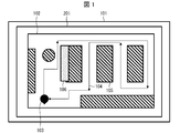
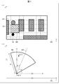
- FIG. 1 is a schematic diagram illustrating an example of a usage mode of the display device 101 according to the first embodiment.
- the display device 101 operates as follows.
- the display device 101 displays the plan view 102 on the display unit 201.
- the display device 101 generates a movement path 104 from a movement start point to a movement end point of the moving body (moving apparatus) 103 and displays the movement path 104 on the plan view 102.
- the display device 101 displays a moving path 104 that passes around a plurality of shelves 105 so as to overlap the plan view 102.
- the display device 101 calculates, for each point in the specific area, a time interval (time interval) outside the work influence, which is an interval from when the work is performed on the point to when the work is performed next. .
- the display device 101 displays the work influence, which is the interval between the time that the work of the moving body 103 has reached and the time that the work has reached, in the entire work influence range that is the range that the work of the moving body 103 has. Calculate the outside time interval.
- the display unit 201 of the display device 101 displays at least a part of the time interval outside the work influence on the plan view 102.
- the non-work-affecting time interval indicates a time interval between monitoring, that is, a non-monitoring time.
- the display device 101 displays a region where the time interval outside the work influence exceeds the threshold as a long time interval region (image indicating a time interval) 106 on the plan view 102.
- the user can recognize an area in which the moving body 103 has not worked for a long time in each work influence range.
- the user can set the movement path 104 based on the long-time interval area 106, for example, such that the moving body 103 moves mainly in an area where the moving body 103 does not perform work for a long time. Therefore, it is possible to assist in appropriately setting the movement route 104 of the moving object 103.
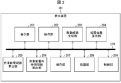
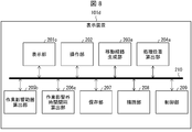
- FIG. 2 is a functional block diagram illustrating a configuration example of the display device 101 according to the first embodiment.
- the display device 101 includes a display unit 201, an operation unit 202, a movement route generation unit 203, a processing position calculation unit 204, a work influence range calculation unit 205, and a time interval calculation outside work influence.
- the unit 206 includes a storage unit 207, a storage unit 207, a drawing unit 208, a control unit 209, and a data bus 210.
- the display unit 201 displays an image generated by the drawing unit 208, a UI (User Interface) for controlling the display device 101, and the like.
- UI User Interface
- the display unit 201 displays the movement route 104 and the long-time interval area (time interval outside the work influence) 106 of the moving body 103. Thus, it is possible to assist in appropriately setting the movement route 104 of the moving object 103.
- the display unit 201 displays the non-work-affected time intervals in the work-affected range based on the photographing range of the photographing unit 1030 (not shown) included in the moving body 103. Accordingly, it is possible to display the time interval outside the work influence in a more preferable work influence range, and it is possible to support setting the movement route 104 of the moving body 103 more appropriately.
- the display unit 201 includes an LCD (Liquid Crystal Display) or an organic EL display (OELD: Organic ElectroLuminescence Display).
- LCD Liquid Crystal Display
- OELD Organic ElectroLuminescence Display
- the operation unit (input unit) 202 receives an input for setting the movement route 104.
- the operation unit 202 may be realized by a function of a touch panel that allows a user to operate a terminal by pressing a screen displayed on the display unit 201.
- the operation unit 202 may be realized by a keyboard and a mouse provided outside the display device 101.
- the movement route generation unit (acquisition unit) 203 generates (acquires) a movement route of the moving body 103 that moves in a specific area while performing a specific operation on the surroundings. Specifically, the movement route generation unit 203 generates the movement route 104 of the moving body 103 on the plan view 102.
- the movement route generation unit 203 generates a movement route based on an input via the operation unit 202. Specifically, the movement route generation unit 203 may generate the movement route 104 by a method of calculating the shortest route from the movement start point and the movement end point input via the operation unit 202. Further, the movement route generation unit 203 may generate the movement route 104 based on the movement route directly input by the user via the operation unit 202.
- the processing position calculation unit (display control unit) 204 calculates a processing position that is the position of the moving object 103 on the plan view 102 at the processing time that is the time when the moving object 103 is working.
- the processing position calculation unit 204 is configured by an FPGA (Field Programmable Gate Array) or an ASIC (Application Specific Integrated Circuit).
- the processing position calculation unit 204 calculates the processing position based on at least the traveling speed and the turning specification of the moving body 103. Note that the processing time described above specifically refers to a time obtained by adding the elapsed time to the time when the moving body 103 has left the movement start point. Further, the processing position calculation unit 204 calculates the optical axis direction of the imaging unit 1030 included in the moving body 103.
- the work influence range calculation unit (display control unit) 205 calculates a work influence range which is a range exerted by the work of the moving body 103.
- the range exerted by the work of the moving body 103 includes, for example, the moving path 104 of the moving body 103. Details of a method of calculating the work influence range by the work influence range calculation unit 205 will be described later.
- the work influence range calculation unit 205 includes an FPGA, an ASIC, and the like.
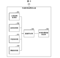
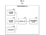
- FIG. 3 is a functional block diagram illustrating a configuration example of the work influence range calculation unit 205 in the display device 101 according to the first embodiment.
- the work influence range calculation unit 205 includes a divided area acquisition unit 301, a view angle acquisition unit 302, an angle acquisition unit 303, a threshold value acquisition unit 304, a coordinate calculation unit 305, and a work influence range. And an extraction unit 306.
- the divided area acquiring unit 301 acquires a divided area which is an image obtained by dividing the plan view 102 into a plurality of divided areas. In one aspect, the divided area acquisition unit 301 acquires the divided area stored in the storage unit 207.
- the angle-of-view acquisition unit 302 acquires the angle of view (angle-of-view information) of the imaging unit 1030 included in the moving object 103.
- the angle-of-view obtaining unit 302 obtains the angle of view stored in the storage unit 207. Further, the angle of view obtaining unit 302 may obtain the angle of view by calculating the angle of view based on the size of the sensor of the imaging unit 1030 and the focal length of the lens of the imaging unit 1030.
- the angle acquisition unit 303 acquires an angle (angle information) between the optical axis direction of the imaging unit 1030 included in the moving body 103 at the processing position of the moving body 103 on the divided area and the coordinate system of the divided area. In one aspect, the angle acquisition unit 303 acquires the processing position and the angle stored in the storage unit 207.
- the threshold obtaining unit 304 obtains a threshold (threshold information) related to a threshold of the distance from the moving object 103 for determining the work influence range.
- the threshold value obtaining unit 304 obtains the threshold value Th stored in the storage unit 207.
- the coordinate calculation unit 305 calculates the coordinates of the divided area included in the field of view (imaging range) of the imaging unit 1030 included in the moving object 103 based on the coordinates of the processing position of the moving object 103, the angle of view, the angle, and the threshold of the imaging unit 1030. Is calculated.
- the work influence range extraction unit 306 extracts the work influence range based on the coordinates on the divided area included in the angle of view of the imaging unit 1030 of the moving body 103 calculated by the coordinate calculation unit 305, and stores the work influence range in the storage unit 207. save.
- the non-work-affected time interval calculation unit (display control unit) 206 calculates a non-work-affected time interval in a plurality of divided regions in the plan view 102. Details of a method of calculating the non-work-affected time interval by the non-work-affected time interval calculation unit 206 will be described later.
- the non-work-effect time interval calculation unit 206 is configured by an FPGA, an ASIC, and the like.
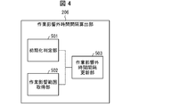
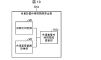
- FIG. 4 is a functional block diagram illustrating a configuration example of the work-influenced time interval calculation unit 206 in the display device 101 according to the first embodiment.
- the non-work-affected time interval calculation unit 206 includes an initialization determination unit 501, a work-affected range acquisition unit 502, and a non-work-affected time interval update unit 503.
- the initialization determination unit 501 determines whether to initialize the non-work-affecting time intervals in each divided area. When the moving object 103 has not yet started moving, the initialization determination unit 501 determines to initialize the non-work-affecting time intervals in each divided area. In addition, when the moving body 103 has already started moving, the initialization determination unit 501 determines not to initialize the non-work-affected time intervals in each of the divided areas.
- the work influence range acquisition unit 502 obtains a work influence range (work influence range information) for each processing position at each time.
- the work influence range acquisition unit 502 acquires the work influence range stored in the storage unit 207.
- the non-work-affected time interval updating unit 503 updates the non-work-affected time interval in each divided area based on the determination by the initialization determination unit 501 and the work-affected range acquired by the work-affected range acquisition unit 502.
- the non-work-affected time interval update unit 503 sets the non-work-affected time interval in the divided area to infinity.
- the time interval outside the work influence set at the time of initialization is not limited to this, and may be any value as long as it is a value that is sufficiently large with respect to the travel time of the moving body 103 on the movement route 104.
- the non-work-affected time interval updating unit 503 determines, based on the work-affected range, a divided region in the plan view 102 that is not included in the work-affected range.
- the time interval outside the work influence is updated by adding the elapsed time from the pre-processing time, which is the time when the work of the moving body 103 last time has reached. Details of the method of calculating the time interval outside the work influence will be described later.
- the storage unit 207 includes a camera parameter of the imaging unit 1030 included in the moving body 103, the movement route 104 generated by the movement route generation unit 203, the work influence range calculated by the work influence range calculation unit 205, and the time interval calculation outside the work influence. The time interval outside the work influence calculated by the unit 206 is stored.
- the storage unit 207 also stores in the storage unit 207 a non-work-affected time interval threshold (non-work-affected time interval threshold information) indicating whether the non-work-affected time interval is greater than or equal to a preset threshold.
- the storage unit 207 includes a storage device such as a random access memory (RAM) and a hard disk drive (HDD).
- the work-influenced time interval threshold may be any value as long as it is not significantly shorter than the traveling time of the moving body 103 on the movement route 104.
- the drawing unit (display control unit) 208 causes the display unit 201 to display an image indicating the time interval outside the work influence on the display unit 201 based on the movement route 104 set by the movement route generation unit 203. Specifically, the drawing unit 208 draws the moving body 103 and the moving path 104 on the plan view 102 by combining the plan view 102 with the moving body 103 and the moving path 104. The drawing unit 208 draws at least a part of the non-work-affected time interval calculated by the non-work-affected time interval calculation unit 206 on the plan view 102.
- the drawing unit 208 draws the long interval area 106 on the plan view 102 by synthesizing the plan view 102 and the long interval area 106 based on the time interval outside the work influence.
- the drawing unit 208 includes an FPGA, an ASIC, and the like.
- the drawing unit 208 refers to the work influence range that is the imaging range of the moving body 103 and indicates the time interval outside the work influence.
- An image (for example, the long time interval area 106) may be displayed on the display unit 201c. Accordingly, when the specific work performed by the moving body 103 is imaging, it is possible to more suitably display the image indicating the time interval outside the work influence on the display unit 201c.
- Control unit 209 performs processing instructions and control in each member (each processing block) included in the display device 101, and controls data input / output.
- control unit 209 is configured by a CPU (Central Processing Unit) or the like.
- the data bus 210 is a bus for exchanging data between each functional block.
- FIG. 5 is a diagram for describing calculation of the work influence range 402 by the work influence range calculation unit 205 in the display device 101 according to the first embodiment.
- FIG. 5A is a diagram for explaining the relationship between the divided area 401 in the plan view 102 and the work influence range 402 of the moving body 103.
- FIG. 5B is a diagram for explaining the calculation of the coordinates of the divided area 401 by the coordinate calculation unit 305 in the work influence range calculation unit 205.
- the divided area acquisition unit 301 of the work influence range calculation unit 205 acquires the divided area 401 obtained by dividing the plan view 102 into a plurality of areas.
- the divided region acquiring unit 301 acquires a divided region 401 obtained by dividing the plan view 102 into rectangles of one or more rows and one or more columns.
- the divided area acquiring unit 301 acquires the divided area 401 obtained by dividing the plan view 102 into a rectangle having 6 rows and 10 columns.
- the divided area 401 of r rows and c columns will be referred to as divided area A (r, c).
- the coordinates (m, n) of the processing position X of the moving body 103 and the coordinates m and p of the coordinates (p, q) of the point P on the coordinate system 403 are the x-axis which is the horizontal direction of the coordinate system 403 of the divided area 401.
- And n and q indicate the coordinates of the y-axis which is the vertical direction of the plan view 102.
- the view angle acquisition unit 302 of the work influence range calculation unit 205 acquires the view angle ⁇ of the imaging unit 1030 included in the moving body 103.
- the angle acquisition unit 303 of the work influence range calculation unit 205 determines the optical axis direction 404 of the imaging unit 1030 provided in the moving body 103 at the processing position X (coordinates (m, n)) of the moving body 103, and the coordinate system 403. Is obtained from the x-axis.
- the threshold acquisition unit 304 of the work influence range calculation unit 205 determines the threshold from the moving object 103 that can be included in the field of view (imaging range) 405 of the imaging unit 1030 included in the moving object 103 stored in the storage unit 207. Get Th.
- the coordinate calculation unit 305 of the work influence range calculation unit 205 calculates the coordinates of the divided area 401 that falls within the field of view 405 of the imaging unit 1030 included in the moving body 103. Specifically, the coordinate calculation unit 305 calculates the coordinates (p, q) of the point P on the coordinate system 403 that falls within the field of view 405 of the imaging unit 1030 included in the moving object 103.
- a method of calculating the coordinates (p, q) of the point P by the coordinate calculation unit 305 will be specifically described.
- the coordinate calculation unit 305 calculates the coordinates (m, n) of the processing position X of the moving body 103, the angle of view ⁇ of the imaging unit 1030, the optical axis direction 404 of the imaging unit 1030 provided in the moving body 103 at the processing position X,
- the coordinates (p, q) of the point P are calculated based on the angle ⁇ between the x-axis of the coordinate system 403 of the divided area 401 and the threshold Th. More specifically, the coordinate calculation unit 305 calculates the coordinates of the coordinates (p, q) of the point P satisfying the following (Equation 1) and (Equation 2).
- the work influence range extraction unit 306 of the work influence range calculation unit 205 extracts the divided area A (r, c) including the coordinates P (p, q) satisfying both (Equation 1) and (Equation 2). , And extract as the work influence range.
- the work influence range extraction unit 306 stores the extracted work influence range in the storage unit 207.
- the work influence range extraction unit 306 works on the divided area A (r, c) including the coordinates P (p, q) satisfying both (Equation 1) and (Equation 2). It is extracted as the area of influence.
- the present embodiment is not limited to this.
- the work influence range extraction unit 306 determines Alternatively, the divided area A (r, c) may be extracted as the work influence range.
- the initialization determination unit 501 of the non-work-affected time interval calculation unit 206 determines whether or not to initialize the non-work-affected time interval in each divided area 401.
- the initialization determination unit 501 determines to initialize the non-work-affecting time intervals in each of the divided areas 401.
- the initialization determination unit 501 sets the non-work-affected time intervals in all the divided areas 401 to infinity, thereby initializing the non-work-affected time intervals in each of the divided areas 401. I do.
- the initialization determination unit 501 determines not to initialize the non-work-affecting time intervals in each of the divided areas 401.
- the work influence range acquisition unit 502 of the work outside influence time interval calculation unit 206 obtains the work influence range stored in the storage unit 207.
- the non-work-influence time interval update unit 503 of the work-influence time interval calculation unit 206 performs the work-influence range acquisition in the area included in the plan view 102 based on the work-affect range acquired from the work-affect range acquisition unit 502.
- the non-work-affected time intervals in all the divided regions 401 are updated.
- the non-work-affected time interval updating unit 503 adds the elapsed time from the pre-processing time to each of the divided areas 401 not included in the work-affected area 402, and thereby calculates the non-work-affected time in all the divided areas 401.
- Update interval The non-work-affected time interval updating unit 503 stores the updated non-work-affected time interval in the storage unit 207 as the non-work-affected time interval in each divided area 401.
- the non-work-affected time interval calculation unit 206 calculates the non-work-affected time interval T (r, c, t) that satisfies the following condition (Equation 3).
- the non-work-affected time interval T (r, c, t) in (Equation 3) is the non-work-affected time interval of the divided area A (r, c) at the processing time t.
- S is a set of divided areas A (r, c, t) included in the work influence range at the processing time t.
- the processing time t ' is a processing time immediately before the processing time t, that is, a time when the moving body 103 worked in the previous divided area A (r, c).
- the method of calculating the time interval outside the work influence is not limited to the above example.
- the work-influenced time interval calculation unit 206 calculates the work-influenced time interval having the largest value in the history of work-influenced time intervals calculated by (Equation 3) and stored in the storage unit 207, The time interval outside the work influence in the entire range 402 may be adopted.
- the drawing unit 208 acquires the non-work-affected time intervals in each of the divided areas 401 calculated by the non-work-affected time interval calculation unit 206.
- the drawing unit 208 acquires the work-influenced time interval threshold value stored in the storage unit 207.
- the drawing unit 208 compares the non-work-affected time interval in each of the acquired divided regions 401 with the non-work-affected time interval threshold. Then, the drawing unit 208 outputs the long-time interval area 106 that is an image indicating an area (point) where the non-work-affected time interval exceeds the threshold value among the non-work-affected time intervals in all the divided areas 401 in the plan view 102. Is displayed on the display unit 201. That is, the long time interval area 106 includes one or a plurality of divided areas 401. Specifically, the drawing unit 208 draws the long time interval area 106 on the corresponding divided area 401 (area corresponding to the divided area 401 in the plan view 102). In one embodiment, as illustrated in FIG. 1, the drawing unit 208 draws the long-time interval area 106 as an image in which a part of the divided area 401 in the plan view 102 is filled.
- Patent Literature 1 at the time of setting the moving route of the moving body, the elapsed time after the moving body is visually recognized at each point on the moving route is not described. For this reason, the above-described related art cannot support setting the moving route of the moving object appropriately.
- the work outside the work-affected time interval is performed for a predetermined time or more.
- the drawing unit 208 is not limited to a form in which the long-time interval area 106 is drawn as an image in which the divided area 401 is filled.
- the drawing unit 208 may draw the time intervals outside the work influence in the divided area 401 of the plan view 102.
- the drawing unit 208 may draw on each of the divided areas 401 using the time intervals outside the work influence in all the divided areas 401 as numerical values.
- the drawing unit 208 can distinguish at least one of the lightness, hue, and transparency of the color to be filled in the long interval area 106 in all the divided areas 401 based on the length of the time interval outside the work influence. You may draw on the division area 401.
- the moving route generation unit 203 may set a suitable moving route 104 of the moving body 103 while changing the threshold value of the time interval outside the work influence to various values by the user.
- the user can input the threshold value of the non-work-affecting time interval into the box, or change the threshold value of the non-work-affecting time interval as appropriate by moving the scroll bar indicating the magnitude of the threshold value of the work-influence time interval.
- the moving route generation unit 203 may be able to set a more suitable moving route 104 of the moving body 103 while confirming changes such as the appearance position and the size of the long time interval area 106.
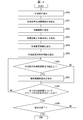
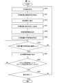
- FIG. 6 is a flowchart illustrating an example of a flow of a control process of the display device 101 according to the first embodiment.
- step S100 the display unit 201 of the display device 101 displays the plan view 102.
- step S101 the non-working time interval calculating unit 206 of the display device 101 initializes the non-working time intervals in all the divided areas 401.
- step S ⁇ b> 102 the movement route generation unit 203 of the display device 101 generates (acquires) the movement route 104 of the moving object 103.
- the display unit 201 displays the movement path 104 of the moving object 103 on the plan view 102.
- step S103 the processing position calculation unit 204 calculates the processing position of the moving body 103 at each processing time and the optical axis direction of the imaging unit 1030 included in the moving body 103.
- step S104 the work influence range calculation unit 205 calculates the work influence range of the moving body 103 at each processing position.
- step S105 the non-work-affected time interval calculating unit 206 calculates the non-work-affected time interval for each divided area 401 based on the work-affected range.
- step S106 the drawing unit 208 compares the non-work-affected time interval with the non-work-affected time interval threshold for each of the divided areas 401.
- the process proceeds to step S107. If the non-working effect time interval in a certain divided area 401 is smaller than the threshold value indicated by the non-working effect time interval threshold (NO in step S106), the process proceeds to step S108.
- step S107 the drawing unit 208 draws the long interval area 106 in the divided area 401 based on the moving path 104 of the moving object 103 generated by the moving path generating unit 203.
- the drawing unit 208 causes the display unit 201 to display the long-time interval area together with the movement route 104.
- the display unit 201 displays the long time interval area 106 on the plan view 102.
- step S108 the drawing unit 208 determines whether or not the processing in step S106 has been performed on all the divided areas 401. If the processing in step S106 has not been performed for all the divided areas 401 (NO in step S108), the processing returns to step S106. When the processing in step S106 has been performed for all the divided areas 401 (YES in step S108), the process proceeds to step S109.
- step S109 the control unit 209 determines whether the display of the movement route 104 and the long-time interval area 106 by the display device 101 has been completed. For example, the control unit 209 determines that the display by the display device 101 has ended when an operation indicating the end of the display is input from the user via the operation unit 202. When the control unit 209 determines that the display by the display device 101 has ended (YES in step S109), the control unit 209 ends the control processing of the display device 101. When the control unit 209 determines that the display by the display device 101 has not ended (NO in step S109), the control unit 209 does not end the display by the display device 101 and returns to the processing of step S100. Then, the display device 101 repeats the processing of steps S100 to S109 described above.
- the display unit 201 of the display device 101 displays the movement path 104 of the moving body 103.
- the display device 101a may actually move the moving body 103 based on the movement path.
- the display device 101a further includes a transmitting unit 1031 (not shown) that transmits a moving route to the moving body 103. Except for this point, the display device 101a has the same configuration as the display device 101 according to the first embodiment.
- the mobile unit 103 in the present embodiment includes a receiving unit 1032 (not shown) and a traveling unit 1033 (not shown).
- the display device 101a transmits the moving route to the moving object 103 via the transmitting unit 1031.
- the moving body 103 moves the moving path 104 by driving the traveling section 1033 based on the moving path received via the receiving section 1032.
- the display device 101 according to the first embodiment is limited to a simulation in which the display device 101 suitably displays the movement route 104 on the display unit 201 before the moving body 103 travels.
- the display device 101a according to the second embodiment after the moving path 104 is appropriately set by the display apparatus 101a before the traveling of the moving body 103, the moving path 104 is actually suitably moved by the moving body 103. be able to.
- the drawing unit 208 of the display device 101 displays the long-time interval area 106 on the divided area 401 based on the non-work-affected time interval of the moving object 103. That is, the display unit 201 does not change the display mode of the long-time interval area 106 depending on whether or not the time intervals outside the work influence in each divided area 401 have the same value.
- the display unit 201a (not shown) of the display device 101b has the same non-work-affecting time interval in each divided region 401,
- the display method of the long time interval area 106 may be changed based on the position of the end point (movement end point) of the moving path 104 of the moving body 103.
- the display device 101b includes a display unit 201a (not shown) and a drawing unit 208a instead of the display unit 201 and the drawing unit 208 in the first embodiment. Except for this point, the display device 101b has the same configuration as the display device 101 according to the first embodiment.
- the drawing unit 208a controls the hue of the long-time interval area 106 based on the non-work-effect time interval. Further, the drawing unit 208a controls the brightness of the long-time interval area 106 based on the length of the Manhattan distance from the divided area 401 including the end point of the moving path 104 of the moving object 103.
- the drawing unit 208a controls so that the user can easily recognize the light by brightening the brightness of the time interval outside the work influence corresponding to the long time interval area 106 having the long distance.
- the display unit 201a changes the display mode of the work-influenced time interval based on the position of the end point of the movement route 104.
- the display unit 201a changes the display mode of the work-influenced time interval based on the position of the end point of the movement route 104.
- the work influence range calculation unit 205 of the display device 101 determines the movement determined based on the coordinates of the processing position of the moving body 103, the angle of view, the angle of the imaging unit 1030, and the threshold.
- the fan-shaped divided area 401 included in the field of view 405 of the imaging unit 1030 included in the body 103 is calculated as the work influence range.
- the work influence range calculation unit 205a of the display device 101c includes, in addition to the fan-shaped divided region 401, a wall existing on the plan view 102, The work influence range may be calculated further based on the occlusion area between the column and shelf 105 and the divided area 401.
- the display device 101c includes a display unit 201b (not shown) and a work influence range calculation unit 205a (not shown) instead of the display unit 201 and the work influence range calculation unit 205 in the first embodiment. Except for this point, the display device 101c has the same configuration as the display device 101 according to the first embodiment.
- the work influence range calculation unit 205a includes a work influence range extraction unit 306a (not shown) instead of the work influence range extraction unit 306 in the first embodiment. Except for this point, the work influence range calculation unit 205a has the same configuration as the work influence range calculation unit 205 in the first embodiment.
- the work influence range extraction unit 306a calculates the work influence range based on the coordinates on the divided region 401 included in the angle of view of the imaging unit 1030 of the moving object 103 and the above-described occlusion calculated by the coordinate calculation unit 305. Extract. For example, when at least one of the wall, the pillar, and the shelf 105 is included in the coordinates on the divided area 401 and the occlusion is set, the work influence range extraction unit 306a removes the occlusion from the divided area 401. The extracted area is extracted as the work influence range. Thus, it is possible to calculate the actual work influence range in consideration of the wall, the pillar, and the shelf 105 existing on the plan view 102.
- the display unit 201b displays an imaging range of the imaging unit 1030 included in the moving object 103 and a time interval outside the work influence in the work influence range based on the occlusion area.
- the display unit 201b displays the long-time interval area 106 in the work influence area based on the shooting area and the occlusion area.
- the long-time interval area 106 based on the actual work influence range in which the wall, the pillar, and the shelf 105 existing on the plan view 102 are also considered can be displayed on the divided area 401.
- the display unit 201 of the display device 101 displays the long-time interval area 106 in the divided area 401 in which the non-work-affected time interval of one moving body 103 exceeds the threshold. I have.
- the display unit 201c of the display device 101d displays the long-time interval area 106 based on the non-work-affecting time intervals of two or more (plural) moving objects. May be.
- FIG. 7 is a schematic diagram illustrating an example of a usage mode of the display device 101d according to the fifth embodiment.
- the display device 101d operates as follows.
- the display device 101d displays the plan view 102 on the display unit 201c.
- the display device 101d generates a movement path 104a from the movement start point to the movement end point of the moving body 103a and a movement path 104b from the movement start point to the movement end point of the moving body 103b, and displays them on the plan view 102.
- the display unit 201c of the display device 101d generates a moving path 104b having a different height from the moving path 104a and displays the moving path 104b on the plan view 102.
- the display device 101d calculates the non-work-affected time interval in the work-affected range of the moving body 103a and the non-work-affected time interval in the work-affected range of the moving body 103b, respectively.
- the display unit 201c of the display device 101d displays, in the plan view 102, the long-time interval area 106 exceeding the threshold value among the time intervals outside the work influence.
- the display unit 201c displays the long-time interval area 106 on the plan view 102 based on the non-work-affected time intervals of the plurality of moving objects 103a and 103b. This is different from the display device 101 according to the first embodiment.
- FIG. 8 is a functional block diagram illustrating a configuration example of a display device 101d according to the fifth embodiment.
- the display device 101d includes a display unit 201, a movement route generation unit 203, a processing position calculation unit 204, a work influence range calculation unit 205, and a work influence non-work time interval calculation unit according to the first embodiment.
- a display unit 201c, a movement route generation unit 203a, a processing position calculation unit 204a, a work influence range calculation unit 205b, and a non-work influence time interval calculation unit 206a are provided. Except for this point, the display device 101d has the same configuration as the display device 101 according to the first embodiment.
- the moving path generation unit 203a generates (acquires) the moving paths (moving paths 104a and 104b) of the plurality of moving objects 103a and 103b on the plan view 102, respectively.
- the moving path generation unit 203a determines that the moving path 104a of the moving body 103a and the moving path 104b of the moving body 103b have different heights. Generate each one differently.
- the processing position calculation unit 204a has the following functions instead of the functions of the processing position calculation unit 204 in the first embodiment.
- the processing position calculation unit 204a calculates the travel time of the moving start points of the moving bodies 103a and 103b based on the moving path 104a of the moving body 103a, the moving path 104b of the moving body 103b, and the traveling specifications of the moving bodies 103a and 103b. Then, the processing position of the moving body 103a and the processing position of the moving body 103b on the plan view 102 at the processing time based on the earlier departure time of the movement start point are calculated. Further, the processing position calculation unit 204a calculates the optical axis direction of the imaging unit 1030 included in the moving body 103a and the optical axis direction of the imaging unit 1030 included in the moving body 103b.
- the work influence range calculation unit 205b replaces the function of the work influence range calculation unit 205 in the first embodiment with the work influence range of the moving body 103a at the processing position of the moving body 103a and the moving body 103b at the processing position of the moving body 103b. And a function for calculating each work influence range.
- the work influence range calculation unit 205b calculates the work influence range of the moving body 103a based on the processing position of the moving body 103a and the work content wa of the moving body 103a.
- the work influence range calculation unit 205b calculates the work influence range of the moving body 103b based on the processing position of the moving body 103b and the work content wb of the moving body 103b.
- FIG. 9 is a functional block diagram illustrating a configuration example of the work influence range calculation unit 205b in the display device 101d according to the fifth embodiment.
- the work influence range calculation unit 205b further includes a work content acquisition unit 307, and includes a work influence range extraction unit 306a instead of the work influence range extraction unit 306 in the first embodiment. Except for this point, the work influence range calculation unit 205b has the same configuration as the work influence range calculation unit 205 in the first embodiment.
- the work content acquisition unit 307 acquires the work content wa of the moving body 103a and the work content wb of the moving body 103b.
- the work content acquisition unit 307 sets the installation height of the imaging unit 1030 included in the moving body 103a stored in the storage unit 207 and the installation height of the imaging unit 1030 included in the moving body 103b as the work content. May be acquired.
- the work content acquired by the work content acquisition unit 307 is not limited to the installation height of the imaging unit 1030 of the moving body 103a and the moving body 103b described above.
- the work content acquired by the work content acquisition unit 307 may be, for example, a wavelength range or a shutter speed in which the imaging unit 1030 of the moving body 103a and the moving body 103b can photograph.
- the work influence range extraction unit 306a determines the divided area A (r, c) based on the divided area A (r, c) including the coordinates within the field of view of the imaging unit 1030 included in the moving body 103a and the work content wa of the moving body 103a. c) extracts the work influence range W (r, c, wa) included in the work influence range of the work content wa. Further, the work-affected-range extracting unit 306a determines the divided area A (r, c) based on the divided area A (r, c) including the coordinates within the field of view of the imaging unit 1030 included in the moving body 103b and the work content wb of the moving body 103b.
- the work influence range extraction unit 306a stores the extracted work influence range W (r, c, wa) of the moving body 103a and the work influence range W (r, c, wb) of the moving body 103b in the storage unit 207.
- the work-influenced time interval calculation unit 206a replaces the function of the work-influenced time interval calculation unit 206 in the first embodiment with the work influence range W (r, c, wa) of the moving body 103a and the work of the moving body 103b.
- a function is provided for calculating the non-work-affected time interval for each divided area 401 based on the influence range W (r, c, wb).
- FIG. 10 is a functional block diagram illustrating a configuration example of the work-influenced time interval calculation unit 206a in the display device 101d according to the fifth embodiment.
- the non-work-affected time interval calculation unit 206a is implemented in the same manner as the first embodiment except that it includes a non-work-affected time interval update unit 503a instead of the non-work-affected time interval update unit 503.
- the configuration is the same as that of the work-influenced time interval calculation unit 206 in the first embodiment.
- the non-work-affected time interval updating unit 503a updates the non-work-affected time interval in each divided area 401 based on the determination by the initialization determination unit 501 and the work-affected range acquired by the work-affected range acquisition unit 502. .
- the non-work-affected time interval update unit 503a executes the non-work-affected time interval update unit 503a similarly to the first embodiment. Update interval.
- the non-work-affected time interval update unit 503a sets the time before the work-affected time interval in the work-affected range W (r, c, wa) of the moving body 103a to the previous time.
- the time interval outside the work influence is updated by adding the elapsed time from the processing time.
- the non-work-affected time interval updating unit 503a adds the elapsed time from the pre-processing time to the non-work-affected time interval in the work-affected range W (r, c, wb) of the moving body 103b, thereby obtaining the work-unaffected time. Update interval.
- the non-work-affected time interval updating unit 503a updates the non-work-affected time interval in the updated work-affected range W (r, c, wa) and the updated work-affected range W (r, c, wb).
- the non-work-affected time interval T (r, c, t) at the processing time t of the divided area A (r, c) is calculated based on the non-work-affected time interval.
- the non-work-affected time interval updating unit 503a updates the non-work-affected time intervals in all the divided areas 401 and stores them in the storage unit 207 as the non-work-affected time intervals in each divided area 401.
- the non-work-affected time interval update unit 503a uses the following (Equation 4) to (Equation 6) to calculate the non-work-affected time interval T () at the processing time t of the divided area A (r, c). r, c, t) are calculated.
- Equation 5 is a set of divided areas A (r, c) included in the work influence range W (r, c, wa).
- Sb in (Equation 6) is a set of divided areas A (r, c) included in the work influence range W (r, c, wb).
- T (r, c, wa, t) in (Equations 4) to (Equation 6) is a time interval outside the work influence of the work content wa at the processing time t of the divided area A (r, c).
- T (r, c, wb, t) is a time interval outside the work influence of the work content wb at the processing time t of the divided area A (r, c).
- T ′ in (Equation 5) and (Equation 6) is the processing time immediately before the processing time t, that is, the time when the moving object 103a or 103b worked in the previous divided area A (r, c).
- the drawing unit 208 generates an image indicating the work-influenced-interval based on the moving paths (moving paths 104a and 104b) of the plurality of moving bodies 103a and 103b, and displays the images indicating the movement paths (moving path) of the plurality of moving bodies 103a and 103b. It is displayed on the display unit 201c together with the travel route 104a and the travel route 104b). Specifically, the drawing unit 208 sets the non-work-affected time interval T (r, r) at the processing time t of all the divided areas 401 calculated by the non-work-affected time interval updating unit 503a, that is, the divided area A (r, c). In c, t), the long-time interval area 106 exceeding the threshold is drawn on the corresponding divided area 401.
- the drawing unit 208 is based on the moving paths (moving paths 104a and 104b) of the moving bodies 103a and 103b.
- An image indicating the time interval outside the work influence (for example, the long time interval area 106) may be displayed on the display unit 201c.
- the drawing unit 208 displays the long-time interval area 106 exceeding the threshold value among the non-work-affected time intervals T (r, c, t) at the processing time t of the divided area A (r, c). 201c may be displayed.
- Display unit 201c displays the long time interval area 106 based on the time intervals outside the work influence of the plurality of moving bodies 103a and 103b. Thus, it is possible to assist in appropriately setting the movement routes 104a and 104b of the plurality of moving bodies 103a and 103b.
- the display unit 201c can display the long time interval area 106 in various modes. For example, the display unit 201c may change and display the color of the long-time interval area 106 according to the installation height of the moving bodies 103a and 103b. Further, the display unit 201c may change the display mode of the long time interval area 106 according to the work content.
- FIG. 11 is a flowchart illustrating an example of a control process flow of the display device 101d according to the fifth embodiment. Steps S2 from 00 to S201 and steps S206 to S209 are the same as steps S100 to 101 and steps S106 to S109 in the control processing of the display device 101 according to the first embodiment, and thus description thereof will be omitted.
- step S202 the movement path generation unit 203a of the display device 101d generates the movement path 104a of the moving body 103a and the movement path 104b of the moving body 103b. Further, the display unit 201c displays the moving path 104a of the moving body 103a and the moving path 104b of the moving body 103b on the plan view 102, respectively.
- step S203 the processing position calculation unit 204a of the display device 101d calculates the processing position of the moving body 103a at each processing time and the optical axis direction of the imaging unit 1030 provided in the moving body 103a. Further, the processing position calculation unit 204a calculates the processing position of the moving body 103b and the optical axis direction of the imaging unit 1030 included in the moving body 103b.
- step S204 the work influence range calculation unit 205b of the display device 101d calculates the work influence range of the moving body 103a at the processing position of the moving body 103a and the work influence range of the moving body 103b at the processing position of the moving body 103b. I do.
- step S205 the non-work-affected time interval calculation unit 206a calculates the work-affected range W (r, c, wa) of the moving body 103a and the work-affected range W (r, c, wb) of the moving body 103b.
- the non-work-influenced time interval T (r, c, t) at the processing time t for all the divided areas A (r, c) is calculated.
- the non-work-affected time interval calculating unit 206a calculates the non-work-affected time interval based on the work of the moving body 103a and the non-work-affected time interval based on the work of the moving body 103b. , The non-work-affected time interval T (r, c, t) at the processing time t of all the divided areas 401, that is, the divided areas A (r, c) is calculated.
- the display unit 201c displays, on the plan view 102, the movement paths 104a and 104b of the plurality of moving bodies 103a and 103b, and the long-time interval area 106 based on the time intervals outside the work influence of the moving bodies 103a and 103b. be able to. As a result, it is possible to assist in appropriately setting the movement routes 104a and 104b of the plurality of moving objects 103a and 103b.
- the non-work-affected time interval updating unit 503a of the display device 101d calculates the non-work-affected time interval of the moving body 103a and the non-work-affected time interval of the moving body 103b as shown in (Equation 4). The longer one is calculated as the non-work-affected time interval T (r, c, t) at the processing time t of the divided area A (r, c).
- the drawing unit 208 draws the long-time interval area 106 exceeding the threshold value on the corresponding divided area 401 in the time interval T (r, c, t) outside the work influence.
- the non-work-affected time interval update unit 503a compares the non-work-affected time interval of the moving body 103a and the non-work-affected time interval of the moving body 103b at the processing time t of the divided area A (r, c). It may be calculated as the time interval T (r, c, t) outside the work influence.
- the drawing unit 208 may display the time interval outside the work influence of the moving body 103a and the time outside work influence of the moving body 103b on the plan view 102. That is, the display unit 201c may display each of the non-work-affecting time intervals of the plurality of moving bodies 103a and 103b.
- the drawing unit 208 may draw, on the plan view 102, the long-time interval area 106 exceeding the threshold value in each of the non-working effect time interval of the moving body 103a and the non-working effect time interval of the moving body 103b. . Further, the drawing unit 208 sets each of the non-work-affecting time interval of the moving body 103a and the work-influenced time interval of the moving body 103b on all the corresponding divided areas 401 regardless of whether or not the threshold is exceeded. You may draw. That is, the display unit 201c may display each of the non-work-affected time intervals of the plurality of moving bodies 103a and 103b on all the corresponding divided areas 401.
- the installation height of the moving body 103a is different from the installation height of the moving body 103b, and the moving path generation unit 203a determines the moving path 104a of the moving body 103a and the moving path 104a of the moving body 103b. Each is generated so that the height is different.
- the present embodiment is not limited to this.
- the movement path generation unit 203a determines whether the movement path 104a of the moving body 103a is equal to the movement height of the moving body 103b.
- the moving route 104b and the moving route 104b may be respectively generated so as to have the same height.
- the work-influenced time interval updating unit 503a calculates the work influence range W (r, c, wa) of the moving body 103a and the work influence range W of the moving body 103b in (Equation 4). After comparing both (r, c, wb), the long non-work-affected time interval is calculated as the non-work-affected time interval T (r, c, t) at the processing time t of the divided area A (r, c). doing.
- the movement route generation unit 203a sets an area in which both the visual fields of the imaging units 1030 included in the plurality of moving bodies 103a and 103b do not fit. May be calculated as the non-work-affected time interval T (r, c, t) at the processing time t of the divided area A (r, c).
- the display unit 201c can display the work-influenced time interval based on an area in which both of the fields of view of the imaging unit 1030 included in the plurality of moving objects 103a and 103b do not fit.
- the display unit 201c can display, on the plan view 102, the long time interval area 106 exceeding the threshold value among the time intervals outside the work influence.
- the specific work performed by the moving body 103 is imaging
- the drawing unit 208 refers to the work influence range based on the imaging range of the moving body 103 and indicates a time interval outside the work influence.
- An image (for example, the long time interval area 106) is displayed on the display unit 201.
- the specific work performed by the moving body 103 is water discharge
- the drawing unit 208 refers to the work influence range based on the water discharge range of the moving body 103 and excludes the work influence.
- An image indicating the time interval may be displayed on the display unit 201d.
- FIG. 12 is a functional block diagram illustrating a configuration example of a display device 101e according to the sixth embodiment.
- the display device 101e includes a display unit 201, a processing position calculation unit 204, a work influence range calculation unit 205, and a non-work influence time interval calculation unit 206 according to the first embodiment. It includes a unit 201d, a processing position calculation unit 204b, a work influence range calculation unit 205c, and a non-work influence time interval calculation unit 206b. Except for this point, the display device 101e has the same configuration as the display device 101 according to the first embodiment.
- the moving body 103 includes a water discharging device 1034 (not shown) instead of the imaging unit 1030.
- the processing position calculation unit 204b calculates the processing position of the moving body 103 at each processing time and the water discharge direction that is the front direction of the water discharge device 1034 provided in the moving body 103.
- the work influence range calculation unit 205c replaces the function of the work influence range calculation unit 205 in the first embodiment with the work influence based on the processing position of the moving body 103 and the water discharge range of the water discharge device 1034 provided in the moving body 103. It has a function to calculate the range.
- FIG. 13 is a functional block diagram illustrating a configuration example of the work influence range calculation unit 205c in the display device 101e according to the sixth embodiment.
- the work influence range calculation unit 205c includes a water discharge range acquisition unit 308 instead of the view angle acquisition unit 302 and the threshold value acquisition unit 304 in the first embodiment. Except for this point, the work influence range calculation unit 205c has the same configuration as the work influence range calculation unit 205 in the first embodiment.
- the water discharge range obtaining unit 308 obtains the water discharge range of the water discharge device 1034 included in the moving body 103.
- the water discharge range obtaining unit 308 can use a method of obtaining, as a water discharge range, an area within a predetermined distance in front of the water discharge device 1034 included in the moving object 103.
- the water discharge range of the water discharge device 1034 included in the moving body 103 is different from the visual field 405 of the imaging unit 1030 included in the mobile body 103 according to the first embodiment, and the water discharge distance of the water discharge device 1034 necessary for calculating the work influence range is predetermined. I have. Therefore, the water discharge range acquisition unit 308 can appropriately acquire information for calculating the work influence range without setting a threshold value of the distance from the moving body 103 for calculating the work influence range.
- the water discharge range obtaining unit 308 may obtain the water discharge range of the water discharge device 1034 based on, for example, the flight behavior of water calculated by a known particle method.
- a method of calculating the flight behavior of water by a known particle method for example, Tatsuya Miyashita, Osamu Sugawa, Yoshitaka Wada, Yasuo Kawaguchi, Construction of a three-dimensional simulation model of water discharge and bubble radiation by the MPS method, Safety Engineering Volume 51, (2012) No. 2, p. 96-105.
- the non-work-affected time interval calculation unit 206b replaces the function of the non-work-affected time interval calculation unit 206 in the first embodiment with each work area 401 based on the work influence range calculated by the work influence range calculation unit 205c. And a function for calculating a time interval outside the work influence, which is an interval between the time spanned by the water discharge operation and the time spanned by the water discharge operation. That is, the non-work-affected time interval calculation unit 206c has a function of calculating the non-work-affected time interval based on the water discharge range of the water discharge device 1034 included in the moving body 103.
- the non-work-affected time interval calculating unit 206b includes a non-work-affected time interval updating unit 503b (not shown) instead of the non-work-affected time interval updating unit 503 in the non-work-affected time interval calculating unit 206 in the first embodiment. I have. Except for this point, the non-work-affected time interval calculation unit 206b has the same configuration as the work-independent time interval calculation unit 206 in the first embodiment.
- the non-work-affected time interval update unit 503b is configured to perform a determination based on the determination by the initialization determination unit 501 and the work-affected range acquired by the work-affected range acquisition unit 502, that is, the water discharge range of the water discharge device 1034 included in the moving body 103.
- the time intervals outside the work influence in each divided area 401 are updated.
- the non-work-affected time interval update unit 503b performs the non-work-affected time interval update unit 503 similarly to the first embodiment. Update interval.
- the work-influenced time interval update unit 503b includes the area included in the plan view 102 in the water discharge range of the water discharge device 1034 included in the moving body 103. By adding the elapsed time from the pre-processing time to the non-working area, the non-working effect time intervals in all the divided areas 401 are updated. In other words, the non-work-affected time interval update unit 503b adds the elapsed time from the pre-processing time to each of the divided regions 401 not included in the water discharge range, and calculates the non-work-affected time intervals in all the divided regions 401. Update.
- the non-work-affected time interval updating unit 503 stores the updated non-work-affected time interval in the storage unit 207 as the non-work-affected time interval in each divided area 401.
- Display unit 201d When the operation of the moving body 103 is water discharge by the water discharging device 1034 provided in the moving body 103, the display unit 201d displays the non-work-affected time interval in the work-affected range based on the water discharging range of the water discharging device 1034. Specifically, the display unit 201d displays the long time interval region 106 in the work influence range based on the water discharge range of the water discharge device 1034. Thereby, even when the operation of the moving body 103 is water discharge by the water discharge device 1034 included in the moving body 103, it is possible to support setting of the movement path 104 of the moving body 103 in a suitable manner.
- FIG. 14 is a flowchart illustrating an example of the flow of a control process of the display device 101e according to the sixth embodiment. Steps S300 to S302 and steps S306 to S309 are the same as steps S100 to 102 and steps S106 to S109 in the control processing of the display device 101 according to the first embodiment, and thus description thereof will be omitted.
- step S303 the processing position calculation unit 204 calculates the processing position of the moving body 103 at each processing time and the water discharge direction that is the front direction of the water discharge device 1034 included in the moving body 103.
- step S304 the work influence range calculation unit 205c calculates the work influence range based on the processing position of the moving body 103 and the water discharge range of the water discharge device 1034 provided in the moving body 103.
- step S305 the non-work-affected time interval calculation unit 206b calculates the non-work-affected time interval for each divided area 401 based on the work influence range calculated by the work influence range calculation unit 205c.
- the work influence range calculation unit 205c of the display device 101e calculates the work influence range based on the processing position of the moving body 103 and the water discharge range.
- the work influence range calculation unit 205d of the display device 101f performs the work based on the watering amount in addition to the processing position and the water discharge range of the moving body 103.
- the influence range may be calculated.
- the display device 101f includes a display unit 201e and a work influence range calculation unit 205d (not shown) instead of the display unit 201d and the work influence range calculation unit 205c in the sixth embodiment. Except for this point, the display device 101f has the same configuration as the display device 101e according to the sixth embodiment.
- the work influence range calculation unit 205d has a function of calculating the work influence range based on the watering amount, in addition to the function of the work influence range calculation unit 205c in the sixth embodiment.
- the work influence range calculation unit 205d includes a work influence range extraction unit 306b instead of the work influence range extraction unit 306 in the sixth embodiment. Except for this point, the work influence range calculation unit 205d has the same configuration as the work influence range calculation unit 205c in the sixth embodiment.
- the work influence range extraction unit 306b calculates the water spray amount in the divided region 401 in addition to the coordinates on the divided region 401 included in the water discharge range of the water discharge device 1034 included in the moving body 103, calculated by the coordinate calculation unit 305. Extract the work influence range.
- the work influence range extraction unit 306b may adjust the value of the watering amount based on the temperature and humidity measured by at least one of a thermometer (not shown) and a hygrometer (not shown).
- the work influence range extraction unit 306 further determines the work influence range based on at least one of the temperature and the humidity, in addition to the coordinates and the watering amount on the divided area 401 included in the water discharge range of the water discharge device 1034 included in the moving body 103. May be extracted. As a result, even if it is included in the work influence range, that is, even if it is included in the water discharge range, the water spray amount is small, and the range in which the work by the moving body 103 is not sufficiently performed does not need to be extracted as the work influence range.
- the display unit 201e displays the water discharge range and the non-work-affected time interval in the work-affected range based on the watering amount. Specifically, the display unit 201e displays the water discharge range and the long time interval area 106 in the work influence range based on the watering amount. Thereby, it is possible to display the long time interval area 106 more appropriately and to assist in setting the movement path 104 of the moving body 103 more appropriately.
- Embodiments 1 to 7 The configurations described in the above embodiments and illustrated in the accompanying drawings are merely examples, and the present invention is not limited to these configurations.
- monitoring and water discharge are described as examples of the operation of the moving body 103.
- the present invention can also be used for harvesting and cleaning fish, displaying cabinets and refilling vending machines.
- the present invention can be variously modified within the scope shown in the claims, and the technical scope of the present invention includes embodiments obtained by appropriately combining technical means disclosed in different embodiments. It is. Further, new technical features can be formed by combining the technical means disclosed in each embodiment.
- each component for realizing each function is described as a different part (member). However, in the present invention, it is not necessary to actually have such a site that can be clearly separated and recognized.
- each component for realizing each function may be configured using, for example, actually different parts, or all components may be mounted on one LSI. Good. That is, it is only necessary to have each component capable of realizing each function regardless of each mounting mode.
- each component can be arbitrarily selected, and an invention having the selected configuration is also included in the technical scope of the present invention.
- the display of the plan view 102, the generation and display of the movement path 104 of the moving objects 103, 103a and 103b, the calculation of the processing position of the moving object 103, the calculation of the work influence range, and the time outside the work influence The case where the calculation of the interval and the calculation and display of the long time interval area 106 are all performed by the display devices 101, 101a, 101b, 101c, 101d, 101e, and 101f is described.
- at least one of the above-described processes may be performed by a terminal or a server other than the above-described display device.
- control blocks of the display devices 101, 101a, 101b, 101c, 101d, 101e, and 101f may be realized by a logic circuit (hardware) formed in an integrated circuit (IC chip) or the like, or may be realized by software. Is also good.
- the display devices 101, 101a, 101b, 101c, 101d, 101e, and 101f include a CPU that executes a command of a display control program that is software for realizing each function, and the display control program and various data are stored in a computer system ( Alternatively, a ROM (Read Only Memory) or a storage device (these are referred to as “recording media”) recorded so as to be readable by a CPU (computer), a RAM (Random Access Memory) for expanding the display control program, and the like. Have. Then, the object of the present invention is achieved by causing the computer system (or CPU) to read and execute the display control program from the recording medium.
- the computer system also includes an OS and hardware such as peripheral devices. If the computer system uses a WWW system, the computer system also includes a homepage providing environment (or display environment).
- the recording medium is a portable medium such as a flexible disk and a magneto-optical disk, a storage device such as a hard disk incorporated in a computer system, and a temporary storage such as a tape, a card, a semiconductor memory, and a programmable logic circuit. It also includes non-tangible media.
- the recording medium also includes a medium that dynamically stores the display control program for a short time, such as a communication line that transmits the display control program via a network such as the Internet or a communication line such as a telephone line. Further, the recording medium includes a medium holding a display control program for a certain period of time, such as a volatile memory in a computer system serving as a server or a client in that case.
- the display control program may be supplied to the computer system via an arbitrary transmission medium (such as a communication network or a broadcast wave) capable of transmitting the display control setting program.
- an arbitrary transmission medium such as a communication network or a broadcast wave
- one embodiment of the present invention can also be realized in the form of a data signal embedded in a carrier wave, in which the display control program is embodied by electronic transmission.
- the display control device includes an acquisition unit that acquires a movement route of a mobile device that moves in a specific area while performing a specific operation with respect to the surroundings, and an acquisition unit that acquires the movement route acquired by the acquisition unit.
- a display control unit for displaying, on the display unit, an image showing a time interval from the time when the work is performed on the point to the time when the work is next performed, for each point in the specific area, based on the movement route.
- the display control unit may cause the display unit to display an image indicating a point where the time interval exceeds a threshold.
- the display control device is the display control device according to the aspect 1 or 2, further comprising an input unit that receives an input for acquiring the movement route, wherein the acquisition unit acquires the movement route based on the input. May be.
- the display control device in any one of the aspects 1 to 3, wherein the obtaining unit obtains a moving route of each of the plurality of mobile devices, and An image indicating the time interval may be displayed on the display unit together with the moving paths of the plurality of moving apparatuses based on the moving paths of the moving apparatuses.
- the display control device is the display control device according to the fourth aspect, wherein the plurality of mobile devices perform different tasks from each other, and the display control unit determines the time interval based on a travel route of each mobile device. May be displayed on the display unit.
- the display control device in any one of the aspects 1 to 5, wherein the specific work is imaging, and the display control unit refers to an imaging range of the moving device.
- An image indicating the time interval may be displayed on the display unit.
- a display control device in any one of the aspects 1 to 5, wherein the specific work is water discharge, and the display control unit refers to a water discharge range of the moving device.
- An image indicating the time interval may be displayed on the display unit.
- the display control device in any one of aspects 1 to 7, may further include a transmission unit that transmits the movement route to the mobile device.
- the control method of the display control device includes: the display control device acquiring a moving path of the moving device that moves in a specific area while performing a specific operation with respect to the surroundings; Based on the acquired moving route, the apparatus displays, for each point in the specific area, an image indicating a time interval from the time when the work is performed on the point to the time when the next work is performed, on the moving route. And displaying it on a display unit.
- the display device may be realized by a computer.
- the display device is realized by a computer by operating the computer as each unit (software element) included in the display device.
- the display control program of the display control device and a computer-readable recording medium recording the same are also included in the scope of the present invention.
Landscapes
- Engineering & Computer Science (AREA)
- Physics & Mathematics (AREA)
- General Physics & Mathematics (AREA)
- Radar, Positioning & Navigation (AREA)
- Remote Sensing (AREA)
- Computer Hardware Design (AREA)
- Theoretical Computer Science (AREA)
- Automation & Control Theory (AREA)
- Controls And Circuits For Display Device (AREA)
- Traffic Control Systems (AREA)
- User Interface Of Digital Computer (AREA)
Abstract
移動装置の移動経路を好適に設定することを支援することを可能とする表示制御装置を提供する。表示装置は、移動体の移動経路を取得する移動経路生成部と、移動経路生成部が取得した移動経路に基づいて、時間間隔を示す画像を、当該移動経路とともに表示部に表示させる描画部と、を備えている。
Description
本発明は、表示制御装置、表示制御装置の制御方法、表示制御プログラムおよび記録媒体に関する。
本願は、2018年10月2日に、日本に出願された特願2018-187616に優先権を主張し、その内容をここに援用する。
本願は、2018年10月2日に、日本に出願された特願2018-187616に優先権を主張し、その内容をここに援用する。
移動装置の移動経路を表示する装置として、従来、カーナビゲーションシステムが利用されている。従来の装置は、移動装置の位置および周辺の地図のみを表示している。移動装置は移動経路上で作業を行うものもあるが、従来の装置は、移動装置が行う作業の及ぼす範囲を考慮していない。
移動装置が行う作業として、例えば、移動装置に取り付けられた撮影装置による監視作業がある。この場合、移動装置の作業の及ぼす範囲は、撮影装置による撮影範囲(監視範囲)となる。ここで、移動装置の移動経路は表示されるが、撮影範囲が表示されない従来の装置では、ユーザは、装置の表示内容から移動装置が監視できない領域を判断できない。その結果、ユーザは、装置が、移動装置の移動経路を好適に設定しているかどうかを判断できないという問題がある。
この問題に対処する技術として、特許文献1には、視認可能な領域を考慮して移動経路を生成する技術が開示されている。
しかしながら、特許文献1に記載の技術によっても、必ずしも移動装置の移動経路を好適に設定することができるわけではない。
本発明の一態様は上記課題に鑑みてなされたものであり、移動装置の移動経路を好適に設定することを支援することを可能とする表示制御装置およびその関連技術を提供することを主たる目的とする。
上記の課題を解決するために、本発明の一態様に係る表示制御装置は、周囲に対して特定の作業を行いながら特定領域内を移動する移動装置の移動経路を取得する取得部と、前記取得部が取得した前記移動経路に基づいて、前記特定領域内の地点ごとの、当該地点に対して作業が行われてから次に作業が行われるまでの時間間隔を示す画像を、当該移動経路とともに表示部に表示させる表示制御部と、を備えている。
本発明の一態様に係る表示制御装置の制御方法は、表示制御装置が、周囲に対して特定の作業を行いながら特定領域内を移動する移動装置の移動経路を取得することと、前記表示制御装置が、取得した前記移動経路に基づいて、前記特定領域内の地点ごとの、当該地点に対して作業が行われてから次に作業が行われるまでの時間間隔を示す画像を、当該移動経路とともに表示部に表示させることと、を包含する。
本発明の一態様によれば、移動装置の移動経路を好適に設定することを支援することを可能とする表示制御装置およびその関連技術を提供することができる。
<実施形態1>
本発明の実施形態1に係る表示装置(表示制御装置)101および表示装置101の制御方法(表示制御装置の制御方法)について、図1~図6を用いて以下に説明する。
本発明の実施形態1に係る表示装置(表示制御装置)101および表示装置101の制御方法(表示制御装置の制御方法)について、図1~図6を用いて以下に説明する。
〔表示装置101〕
まず、表示装置101の使用態様について図1を用いて説明する。図1は、実施形態1に係る表示装置101の使用態様の一例を示す模式図である。
まず、表示装置101の使用態様について図1を用いて説明する。図1は、実施形態1に係る表示装置101の使用態様の一例を示す模式図である。
表示装置101は、以下のように動作する。表示装置101は、表示部201に平面図102を表示する。表示装置101は、移動体(移動装置)103の移動開始点から移動終了点までの移動経路104を生成し、平面図102に表示する。図1では、表示装置101は、複数の棚105の周囲を通過するような移動経路104を平面図102に重ねて表示している。続いて、表示装置101は、特定領域内の地点ごとの、当該地点に対して作業が行われてから次に作業が行われるまでの間隔である作業影響外時間間隔(時間間隔)を算出する。具体的には、表示装置101は、移動体103の作業が及ぶ範囲である作業影響範囲全体における、移動体103の作業が及んだ時間と作業が及んだ時間との間隔である作業影響外時間間隔を算出する。表示装置101の表示部201は、作業影響外時間間隔の少なくとも一部を平面図102に表示する。ここで、作業影響外時間間隔とは、例えば、移動体103の作業が監視である場合、監視と監視との時間間隔、すなわち、監視していない時間を表す。図1では、表示装置101は、作業影響外時間間隔が閾値を超える領域を平面図102に長時間間隔領域(時間間隔を示す画像)106として重ねて表示する。
これにより、ユーザは長時間間隔領域106を確認することで、移動体103が各々の作業影響範囲のうち、長時間作業を行っていない領域を認識することができる。その結果、ユーザは、長時間間隔領域106に基づき、例えば、移動体103が長時間作業を行わない領域も重点的に移動体103が移動するような移動経路104を設定することができる。そのため、移動体103の移動経路104を好適に設定することを支援することができる。
次に、実施形態1に係る表示装置101の構成を、図2を用いて説明する。図2は、実施形態1に係る表示装置101の構成例を示す機能ブロック図である。図2に示すように、表示装置101は、表示部201と、操作部202と、移動経路生成部203と、処理位置算出部204と、作業影響範囲算出部205と、作業影響外時間間隔算出部206と、保存部207と、描画部208と、制御部209と、データバス210とを備えている。
[表示部201]
表示部201は、描画部208が生成した画像および表示装置101を制御するためのUI(User Interface)などを表示する。
表示部201は、描画部208が生成した画像および表示装置101を制御するためのUI(User Interface)などを表示する。
具体的には、表示部201は、移動体103の移動経路104および長時間間隔領域(作業影響外時間間隔)106を表示する。これにより、移動体103の移動経路104を好適に設定することを支援することができる。また、表示部201は、移動体103が備える撮影部1030(不図示)の撮影範囲に基づく作業影響範囲における作業影響外時間間隔を表示する。これにより、より好適な作業影響範囲における作業影響外時間間隔を表示することができるようになるため、移動体103の移動経路104をより好適に設定することを支援することができる。
一態様において、表示部201は、LCD(Liquid Crystal Display)または有機ELディスプレイ(OELD:Organic ElectroLuminescence Display)などによって構成される。
[操作部202]
操作部(入力部)202は移動経路104を設定するための入力を受け付ける。一態様において、操作部202は、ユーザが表示部201に表示された画面を押すことで端末を操作することができるようなタッチパネルの機能によって実現されてもよい。また、操作部202は、表示装置101の外部に設けられたキーボードおよびマウスによって実現されてもよい。
操作部(入力部)202は移動経路104を設定するための入力を受け付ける。一態様において、操作部202は、ユーザが表示部201に表示された画面を押すことで端末を操作することができるようなタッチパネルの機能によって実現されてもよい。また、操作部202は、表示装置101の外部に設けられたキーボードおよびマウスによって実現されてもよい。
[移動経路生成部203]
移動経路生成部(取得部)203は、周囲に対して特定の作業を行いながら特定領域内を移動する移動体103の移動経路を生成(取得)する。具体的には、移動経路生成部203は、平面図102上における移動体103の移動経路104を生成する。
移動経路生成部(取得部)203は、周囲に対して特定の作業を行いながら特定領域内を移動する移動体103の移動経路を生成(取得)する。具体的には、移動経路生成部203は、平面図102上における移動体103の移動経路104を生成する。
一態様において、移動経路生成部203は、操作部202を介した入力に基づいて、移動経路を生成する。具体的には、移動経路生成部203は、操作部202を介して入力された移動開始点と、移動終了点とから最短経路を算出する方法によって移動経路104を生成してもよい。また、移動経路生成部203は、操作部202を介して、ユーザによって直接入力された移動経路に基づいて移動経路104を生成してもよい。
[処理位置算出部204]
処理位置算出部(表示制御部)204は、移動体103が作業している時刻である処理時刻における平面図102上の移動体103の位置である処理位置を算出する。一態様において、処理位置算出部204は、FPGA(Field Programmable Gate Array)またはASIC(Application Specific Integrated Circuit)などによって構成される。処理位置算出部204は、少なくとも移動体103の移動速度および旋回速度である走行仕様に基づいて処理位置を算出する。なお、上述の処理時刻とは、具体的には、移動体103が移動開始点を出発した時刻に経過時間を加算した時刻のことを指す。また、処理位置算出部204は、移動体103が備える撮影部1030の光軸方向を算出する。
処理位置算出部(表示制御部)204は、移動体103が作業している時刻である処理時刻における平面図102上の移動体103の位置である処理位置を算出する。一態様において、処理位置算出部204は、FPGA(Field Programmable Gate Array)またはASIC(Application Specific Integrated Circuit)などによって構成される。処理位置算出部204は、少なくとも移動体103の移動速度および旋回速度である走行仕様に基づいて処理位置を算出する。なお、上述の処理時刻とは、具体的には、移動体103が移動開始点を出発した時刻に経過時間を加算した時刻のことを指す。また、処理位置算出部204は、移動体103が備える撮影部1030の光軸方向を算出する。
[作業影響範囲算出部205]
作業影響範囲算出部(表示制御部)205は、移動体103の作業の及ぼす範囲である作業影響範囲を算出する。移動体103の作業の及ぼす範囲としては、例えば、移動体103の移動経路104が挙げられる。作業影響範囲算出部205による作業影響範囲の算出方法の詳細は後述する。一態様において、作業影響範囲算出部205は、FPGAおよびASICなどによって構成される。
作業影響範囲算出部(表示制御部)205は、移動体103の作業の及ぼす範囲である作業影響範囲を算出する。移動体103の作業の及ぼす範囲としては、例えば、移動体103の移動経路104が挙げられる。作業影響範囲算出部205による作業影響範囲の算出方法の詳細は後述する。一態様において、作業影響範囲算出部205は、FPGAおよびASICなどによって構成される。
以下に、図3を用いて作業影響範囲算出部205について、より詳細に説明する。図3は、実施形態1に係る表示装置101における作業影響範囲算出部205の構成例を示す機能ブロック図である。図3に示すように、作業影響範囲算出部205は、分割領域取得部301と、画角取得部302と、角度取得部303と、閾値取得部304と、座標算出部305と、作業影響範囲抽出部306とを備えている。
(分割領域取得部301)
分割領域取得部301は、平面図102を複数の分割領域に分割した画像である分割領域を取得する。一態様において、分割領域取得部301は、保存部207に保存されている分割領域を取得する。
分割領域取得部301は、平面図102を複数の分割領域に分割した画像である分割領域を取得する。一態様において、分割領域取得部301は、保存部207に保存されている分割領域を取得する。
(画角取得部302)
画角取得部302は、移動体103が備える撮影部1030の画角(画角情報)を取得する。一態様において、画角取得部302は、保存部207に保存されている画角を取得する。また、画角取得部302は、撮影部1030のセンサーのサイズと、撮影部1030のレンズの焦点距離とに基づいて、画角を算出することによって取得してもよい。
画角取得部302は、移動体103が備える撮影部1030の画角(画角情報)を取得する。一態様において、画角取得部302は、保存部207に保存されている画角を取得する。また、画角取得部302は、撮影部1030のセンサーのサイズと、撮影部1030のレンズの焦点距離とに基づいて、画角を算出することによって取得してもよい。
(角度取得部303)
角度取得部303は、分割領域上の移動体103の処理位置における移動体103が備える撮影部1030の光軸方向と、分割領域の座標系とがなす角度(角度情報)を取得する。一態様において、角度取得部303は、保存部207に保存されている処理位置および角度を取得する。
角度取得部303は、分割領域上の移動体103の処理位置における移動体103が備える撮影部1030の光軸方向と、分割領域の座標系とがなす角度(角度情報)を取得する。一態様において、角度取得部303は、保存部207に保存されている処理位置および角度を取得する。
(閾値取得部304)
閾値取得部304は、作業影響範囲を決定するための移動体103からの距離の閾値に関する閾値(閾値情報)を取得する。一態様において、閾値取得部304は、保存部207に保存されている閾値Thを取得する。
閾値取得部304は、作業影響範囲を決定するための移動体103からの距離の閾値に関する閾値(閾値情報)を取得する。一態様において、閾値取得部304は、保存部207に保存されている閾値Thを取得する。
(座標算出部305)
座標算出部305は、移動体103の処理位置の座標、撮影部1030の画角、角度および閾値に基づき、移動体103が備える撮影部1030の視野(撮影範囲)内に含まれる分割領域の座標を算出する。
座標算出部305は、移動体103の処理位置の座標、撮影部1030の画角、角度および閾値に基づき、移動体103が備える撮影部1030の視野(撮影範囲)内に含まれる分割領域の座標を算出する。
(作業影響範囲抽出部306)
作業影響範囲抽出部306は、座標算出部305によって算出された、移動体103の撮影部1030の画角内に含まれる分割領域上の座標に基づいて作業影響範囲を抽出し、保存部207に保存する。
作業影響範囲抽出部306は、座標算出部305によって算出された、移動体103の撮影部1030の画角内に含まれる分割領域上の座標に基づいて作業影響範囲を抽出し、保存部207に保存する。
[作業影響外時間間隔算出部206]
作業影響外時間間隔算出部(表示制御部)206は、平面図102における複数の分割領域において、作業影響外時間間隔を算出する。作業影響外時間間隔算出部206による作業影響外時間間隔の算出方法の詳細は後述する。一態様において、作業影響外時間間隔算出部206は、FPGAおよびASICなどによって構成される。
作業影響外時間間隔算出部(表示制御部)206は、平面図102における複数の分割領域において、作業影響外時間間隔を算出する。作業影響外時間間隔算出部206による作業影響外時間間隔の算出方法の詳細は後述する。一態様において、作業影響外時間間隔算出部206は、FPGAおよびASICなどによって構成される。
以下に、図4を用いて作業影響外時間間隔算出部206について、より詳細に説明する。図4は、実施形態1に係る表示装置101における作業影響外時間間隔算出部206の構成例を示す機能ブロック図である。図4に示すように、作業影響外時間間隔算出部206は、初期化判定部501と、作業影響範囲取得部502と、作業影響外時間間隔更新部503とを備えている。
(初期化判定部501)
初期化判定部501は、各々の分割領域における作業影響外時間間隔を初期化するか否かの判定を行う。初期化判定部501は、移動体103が移動を開始する前である場合には、各々の分割領域における作業影響外時間間隔を初期化するように判定する。また、初期化判定部501は、移動体103が既に移動を開始している場合には、各々の分割領域における作業影響外時間間隔を初期化しないように判定する。
初期化判定部501は、各々の分割領域における作業影響外時間間隔を初期化するか否かの判定を行う。初期化判定部501は、移動体103が移動を開始する前である場合には、各々の分割領域における作業影響外時間間隔を初期化するように判定する。また、初期化判定部501は、移動体103が既に移動を開始している場合には、各々の分割領域における作業影響外時間間隔を初期化しないように判定する。
(作業影響範囲取得部502)
作業影響範囲取得部502は、各々の時刻における各々の処理位置に対する作業影響範囲(作業影響範囲情報)を取得する。一態様において、作業影響範囲取得部502は、保存部207に保存されている作業影響範囲を取得する。
作業影響範囲取得部502は、各々の時刻における各々の処理位置に対する作業影響範囲(作業影響範囲情報)を取得する。一態様において、作業影響範囲取得部502は、保存部207に保存されている作業影響範囲を取得する。
(作業影響外時間間隔更新部503)
作業影響外時間間隔更新部503は、初期化判定部501による判定と、作業影響範囲取得部502が取得した作業影響範囲とに基づいて、各々の分割領域における作業影響外時間間隔を更新する。
作業影響外時間間隔更新部503は、初期化判定部501による判定と、作業影響範囲取得部502が取得した作業影響範囲とに基づいて、各々の分割領域における作業影響外時間間隔を更新する。
一態様において、初期化判定部501が作業影響外時間間隔を初期化するように判定した場合、作業影響外時間間隔更新部503は、分割領域における作業影響外時間間隔を無限大に設定する。なお、初期化時に設定される作業影響外時間間隔としてはこれに限定されず、移動体103による移動経路104の走行時間に対して十分に大きい値であれば、どのような値でもよい。また、初期化判定部501が初期化しないように判定した場合、作業影響外時間間隔更新部503は、作業影響範囲に基づき、平面図102における分割領域のうち、作業影響範囲に含まれない分割領域について、前回、移動体103の作業が及んだ時刻である前処理時刻からの経過時間を加算することで、作業影響外時間間隔を更新する。作業影響外時間間隔の算出方法の詳細については後述する。
[保存部207]
保存部207は、移動体103が備える撮影部1030のカメラパラメータ、移動経路生成部203が生成した移動経路104、作業影響範囲算出部205が算出した作業影響範囲、および、作業影響外時間間隔算出部206が算出した作業影響外時間間隔などを保存する。また、保存部207は、作業影響外時間間隔があらかじめ設定された閾値以上であるか否かを示す作業影響外時間間隔閾値(作業影響外時間間隔閾値情報)を保存部207に保存する。一態様において、保存部207は、RAM(Random Access Memory)およびHDD(Hard Disk Drive)などの記憶装置によって構成される。
保存部207は、移動体103が備える撮影部1030のカメラパラメータ、移動経路生成部203が生成した移動経路104、作業影響範囲算出部205が算出した作業影響範囲、および、作業影響外時間間隔算出部206が算出した作業影響外時間間隔などを保存する。また、保存部207は、作業影響外時間間隔があらかじめ設定された閾値以上であるか否かを示す作業影響外時間間隔閾値(作業影響外時間間隔閾値情報)を保存部207に保存する。一態様において、保存部207は、RAM(Random Access Memory)およびHDD(Hard Disk Drive)などの記憶装置によって構成される。
なお、作業影響外時間間隔閾値は、移動体103による移動経路104の走行時間より著しく短い時間でなければ、どのような値であってもよい。
[描画部208]
描画部(表示制御部)208は、移動経路生成部203が設定した移動経路104に基づいて、作業影響外時間間隔を示す画像を、当該移動経路104とともに表示部201に表示させる。具体的には、描画部208は、平面図102と、移動体103および移動経路104とを合成することで、平面図102に移動体103および移動経路104を描画する。また、描画部208は、作業影響外時間間隔算出部206が算出した作業影響外時間間隔の少なくとも一部を平面図102に描画する。例えば、描画部208は、作業影響外時間間隔に基づき、平面図102と長時間間隔領域106とを合成することで、平面図102に長時間間隔領域106を描画する。一態様において、描画部208は、FPGAおよびASICなどによって構成される。
描画部(表示制御部)208は、移動経路生成部203が設定した移動経路104に基づいて、作業影響外時間間隔を示す画像を、当該移動経路104とともに表示部201に表示させる。具体的には、描画部208は、平面図102と、移動体103および移動経路104とを合成することで、平面図102に移動体103および移動経路104を描画する。また、描画部208は、作業影響外時間間隔算出部206が算出した作業影響外時間間隔の少なくとも一部を平面図102に描画する。例えば、描画部208は、作業影響外時間間隔に基づき、平面図102と長時間間隔領域106とを合成することで、平面図102に長時間間隔領域106を描画する。一態様において、描画部208は、FPGAおよびASICなどによって構成される。
また、上述の例のように、移動体103が行う特定の作業が撮像である場合、描画部208は、移動体103の撮像範囲である作業影響範囲を参照して作業影響外時間間隔を示す画像(例えば、長時間間隔領域106)を表示部201cに表示させてもよい。これにより、移動体103が行う特定の作業が撮像である場合に、より好適に作業影響外時間間隔を示す画像を表示部201cに表示させることができる。
[制御部209]
制御部209は、表示装置101が備える各部材(各処理ブロック)における処理の命令および制御ならびにデータの入出力に関するコントロールを行う。一態様において、制御部209は、CPU(Central Processing Unit)などによって構成される。
制御部209は、表示装置101が備える各部材(各処理ブロック)における処理の命令および制御ならびにデータの入出力に関するコントロールを行う。一態様において、制御部209は、CPU(Central Processing Unit)などによって構成される。
[データバス210]
データバス210は、各々の機能ブロック間における、データのやり取りを行うためのバスである。
データバス210は、各々の機能ブロック間における、データのやり取りを行うためのバスである。
〔作業影響範囲の算出〕
以下に、作業影響範囲算出部205による作業影響範囲の算出方法について、図5を用いて説明する。図5は、実施形態1に係る表示装置101における作業影響範囲算出部205による作業影響範囲402の算出について説明するための図である。具体的には、図5の(a)は、平面図102における分割領域401と、移動体103の作業影響範囲402との関係を説明するための図である。図5の(b)は、作業影響範囲算出部205における座標算出部305による分割領域401の座標の算出について説明するための図である。
以下に、作業影響範囲算出部205による作業影響範囲の算出方法について、図5を用いて説明する。図5は、実施形態1に係る表示装置101における作業影響範囲算出部205による作業影響範囲402の算出について説明するための図である。具体的には、図5の(a)は、平面図102における分割領域401と、移動体103の作業影響範囲402との関係を説明するための図である。図5の(b)は、作業影響範囲算出部205における座標算出部305による分割領域401の座標の算出について説明するための図である。
まず、作業影響範囲算出部205の分割領域取得部301は、平面図102を複数の領域に分割した分割領域401を取得する。分割領域取得部301は、平面図102が1以上の行および1以上の列の矩形に分割された分割領域401を取得する。例えば、図5の(a)に示すように、分割領域取得部301は、平面図102が6行10列の矩形に分割された分割領域401を取得する。なお、以下では、複数の分割領域401のうち、r行c列の分割領域401を分割領域A(r,c)と記載する。また、移動体103の処理位置Xの座標(m,n)および座標系403上の点Pの座標(p,q)のmおよびpは分割領域401の座標系403の水平方向であるx軸の座標を指し、nおよびqは平面図102の鉛直方向であるy軸の座標を指す。
続いて、作業影響範囲算出部205の画角取得部302は、移動体103が備える撮影部1030の画角θを取得する。
続いて、作業影響範囲算出部205の角度取得部303は、移動体103の処理位置X(座標(m,n))における移動体103が備える撮影部1030の光軸方向404と、座標系403のx軸とがなす角度αを取得する。
続いて、作業影響範囲算出部205の閾値取得部304は、保存部207に保存されている移動体103が備える撮影部1030の視野(撮影範囲)405に含めることができる移動体103からの閾値Thを取得する。
続いて、作業影響範囲算出部205の座標算出部305は、移動体103が備える撮影部1030の視野405内に収まる分割領域401の座標を算出する。具体的には、座標算出部305は、移動体103が備える撮影部1030の視野405内に収まる座標系403上の点Pの座標(p,q)を算出する。以下に、座標算出部305による点Pの座標(p,q)の算出方法について具体的に説明する。座標算出部305は、移動体103の処理位置Xの座標(m,n)と、撮影部1030の画角θと、処理位置Xにおける移動体103が備える撮影部1030の光軸方向404と、分割領域401の座標系403のx軸とがなす角度αと、閾値Thとに基づいて、点Pの座標(p,q)を算出する。より具体的には、座標算出部305は、以下の(式1)および(式2)を満たす点Pの座標(p,q)の座標を算出する。

最後に、作業影響範囲算出部205の作業影響範囲抽出部306は、(式1)と(式2)との両方を満たす座標P(p,q)からなる分割領域A(r,c)を、作業影響範囲として抽出する。作業影響範囲抽出部306は、抽出した作業影響範囲を保存部207に保存する。
なお、上述の例では、作業影響範囲抽出部306は、上述の(式1)と(式2)との両方を満たす座標P(p,q)からなる分割領域A(r,c)を作業影響範囲として抽出している。ただし、本実施形態ではこれに限定されるものではない。例えば、作業影響範囲抽出部306は、(式1)と(式2)との両方を満たす座標P(p,q)が分割領域A(r,c)に一定の割合以上含まれていれば、当該分割領域A(r,c)を作業影響範囲として抽出してもよい。
〔作業影響外時間間隔の算出〕
以下に、作業影響外時間間隔算出部206による作業影響外時間間隔の算出方法について説明する。
以下に、作業影響外時間間隔算出部206による作業影響外時間間隔の算出方法について説明する。
まず、作業影響外時間間隔算出部206の初期化判定部501は、各々の分割領域401における作業影響外時間間隔を初期化するか否かの判定を行う。初期化判定部501は、移動体103が移動を開始する前である場合には、各々の分割領域401における作業影響外時間間隔を初期化するように判定する。初期化するように判定した場合、初期化判定部501は、全ての分割領域401における作業影響外時間間隔を無限大に設定することで、各々の分割領域401における作業影響外時間間隔を初期化する。また、初期化判定部501は、移動体103が既に移動を開始している場合には、各々の分割領域401における作業影響外時間間隔を初期化しないように判定する。
続いて、作業影響外時間間隔算出部206の作業影響範囲取得部502は、保存部207に保存されている作業影響範囲を取得する。
続いて、作業影響外時間間隔算出部206の作業影響外時間間隔更新部503は、作業影響範囲取得部502から取得した作業影響範囲に基づいて、平面図102に含まれる領域のうち、作業影響範囲402に含まれない領域について、前処理時刻からの経過時間を加算することで、全ての分割領域401における作業影響外時間間隔を更新する。換言すれば、作業影響外時間間隔更新部503は、作業影響範囲402に含まれない分割領域401ごとに前処理時刻からの経過時間を加算することで、全ての分割領域401における作業影響外時間間隔を更新する。作業影響外時間間隔更新部503は、更新した当該作業影響外時間間隔を、各々の分割領域401における作業影響外時間間隔として保存部207に保存する。
より具体的には、作業影響外時間間隔算出部206は、以下の(式3)の条件を満たす作業影響外時間間隔T(r,c,t)を算出する。

(式3)における作業影響外時間間隔T(r,c,t)は、処理時刻tにおける分割領域A(r,c)の作業影響外時間間隔である。Sは、処理時刻tにおける作業影響範囲に含まれる分割領域A(r,c,t)の集合である。処理時刻t’は、処理時刻tの1つ前の処理時刻、すなわち、前回、分割領域A(r,c)において移動体103が作業した時刻である。
なお、作業影響外時間間隔の算出方法は、上述の例に限定されない。例えば、作業影響外時間間隔算出部206は、(式3)によって算出され、保存部207に保存された作業影響外時間間隔の履歴の中で最も大きい値の作業影響外時間間隔を、作業影響範囲402全体における作業影響外時間間隔として採用してもよい。
〔作業影響外時間間隔の描画〕
以下に、描画部208による作業影響外時間間隔の描画方法について説明する。ここでは、描画部208は、算出された作業影響外時間間隔のうちの一部である長時間間隔領域106を描画する方法について説明する。まず、描画部208は、作業影響外時間間隔算出部206が算出した各々の分割領域401における作業影響外時間間隔を取得する。
以下に、描画部208による作業影響外時間間隔の描画方法について説明する。ここでは、描画部208は、算出された作業影響外時間間隔のうちの一部である長時間間隔領域106を描画する方法について説明する。まず、描画部208は、作業影響外時間間隔算出部206が算出した各々の分割領域401における作業影響外時間間隔を取得する。
続いて、描画部208は、保存部207に保存されている作業影響外時間間隔閾値を取得する。
続いて、描画部208は、取得した各々の分割領域401における作業影響外時間間隔と、作業影響外時間間隔閾値とを比較する。そして、描画部208は、平面図102の全ての分割領域401における作業影響外時間間隔のうち、作業影響外時間間隔が閾値を超えている領域(地点)を示す画像である長時間間隔領域106を、表示部201に表示させる。すなわち、長時間間隔領域106は、1つまたは複数の分割領域401により構成される。具体的には、描画部208は、長時間間隔領域106を、対応する分割領域401(平面図102のうち、分割領域401に該当する領域)上に描画する。一態様において、描画部208は、図1に示すように、長時間間隔領域106を、平面図102における分割領域401の一部を塗りつぶした画像として描画する。
ここで、特許文献1に記載されているような従来技術は、移動体の移動経路の設定時に、移動経路の各地点において移動体が視認してからの経過時間については記載されていない。そのため、上述のような従来技術では、移動体の移動経路を好適に設定することを支援することができない。
これに対し、上述のように、作業影響外時間間隔の少なくとも一部を分割領域401に描画することで、上述の例のように、例えば、作業影響外時間間隔のうち、所定の時間以上作業を行っていない分割領域401をユーザに好適に知らせることができる。これにより、所定の時間以上作業を行っていない分割領域401周辺を移動体103に移動させることをユーザに想起させ、より好適な移動体103の移動経路104を設定することをユーザに促すことができる。その結果、移動体103の移動経路104を好適に設定することを支援することができる。
なお、本実施形態では、描画部208は、分割領域401を塗りつぶした画像として長時間間隔領域106を描画する形態に限定されない。本実施形態では、描画部208は、作業影響外時間間隔を平面図102の分割領域401に描画すればよい。例えば、描画部208は、全ての分割領域401における作業影響外時間間隔を数値として各々の分割領域401上に描画してもよい。また、描画部208は、全ての分割領域401における長時間間隔領域106について、作業影響外時間間隔の長短に基づいて、塗りつぶす色の明度、色相および透過度などの少なくとも1つを区別できるように分割領域401上に描画してもよい。
また、ユーザに作業影響外時間間隔の閾値を様々な値に変更させながら、移動経路生成部203は、好適な移動体103の移動経路104を設定してもよい。例えば、作業影響外時間間隔の閾値をボックスに入力するか、作業影響外時間間隔の閾値の大きさを示すスクロールバーを動かすことにより作業影響外時間間隔の閾値を適宜変更することで、ユーザに長時間間隔領域106の出現位置および大きさなどの変化を確認させながら、移動経路生成部203は、より好適な移動体103の移動経路104を設定できるようにしてもよい。
〔表示装置101の制御処理〕
本実施形態1に係る表示装置101の制御処理(表示制御装置の制御方法)について、図6を用いて以下に説明する。図6は、実施形態1に係る表示装置101の制御処理の流れの一例を示すフローチャートである。
本実施形態1に係る表示装置101の制御処理(表示制御装置の制御方法)について、図6を用いて以下に説明する。図6は、実施形態1に係る表示装置101の制御処理の流れの一例を示すフローチャートである。
ステップS100において、表示装置101の表示部201は、平面図102を表示する。
ステップS101において、表示装置101の作業影響外時間間隔算出部206は、全ての分割領域401における作業影響外時間間隔を初期化する。
ステップS102において、表示装置101の移動経路生成部203は、移動体103の移動経路104を生成(取得)する。また、表示部201は、移動体103の移動経路104を平面図102上に表示する。
ステップS103において、処理位置算出部204は、各処理時刻における移動体103の処理位置と、移動体103が備える撮影部1030の光軸方向とを算出する。
ステップS104において、作業影響範囲算出部205は、各処理位置における移動体103の作業影響範囲を算出する。
ステップS105において、作業影響外時間間隔算出部206は、作業影響範囲に基づいて、分割領域401ごとに作業影響外時間間隔を算出する。
ステップS106において、描画部208は、分割領域401ごとに作業影響外時間間隔と、作業影響外時間間隔閾値とを比較する。ある分割領域401における作業影響外時間間隔が、作業影響外時間間隔閾値が示す閾値以上の場合(ステップS106のYES)、ステップS107の処理に進む。ある分割領域401における作業影響外時間間隔が、作業影響外時間間隔閾値が示す閾値未満の場合(ステップS106のNO)、ステップS108の処理に進む。
ステップS107において、描画部208は、移動経路生成部203が生成した移動体103の移動経路104に基づいて、分割領域401に長時間間隔領域106を描画する。これにより、描画部208は、長時間間隔領域を、移動経路104とともに表示部201に表示させる。また、表示部201は、長時間間隔領域106を平面図102上に表示する。
ステップS108において、描画部208は、全ての分割領域401についてステップS106の処理を行ったか否かの判定を行う。全ての分割領域401についてステップS106の処理を行っていない場合(ステップS108のNO)、ステップS106の処理に戻る。全ての分割領域401についてステップS106の処理を行った場合(ステップS108のYES)、ステップS109の処理に進む。
ステップS109において、制御部209は表示装置101による移動経路104および長時間間隔領域106などの表示が終了したか否かを判定する。例えば、制御部209は、操作部202を介してユーザから表示の終了を示す操作が入力された場合に、表示装置101による表示が終了したと判定する。表示装置101による表示が終了したと制御部209が判定した場合(ステップS109のYES)、制御部209は表示装置101の制御処理を終了する。表示装置101による表示が終了していないと制御部209が判定した場合(ステップS109のNO)、制御部209は表示装置101による表示を終了せず、ステップS100の処理に戻る。そして、表示装置101は、上述したステップS100~S109の処理を繰り返す。
〔実施形態1に係る表示装置101による効果〕
実施形態1に係る表示装置101によれば、移動体103の移動経路104を好適に設定することを支援することができる。これにより、例えば、移動体103が監視するという作業を行う場合、移動体103の作業影響外時間間隔、すなわち、監視していない時間が長くなることにより、監視対象を見失うなどの問題を防ぐことができる。
実施形態1に係る表示装置101によれば、移動体103の移動経路104を好適に設定することを支援することができる。これにより、例えば、移動体103が監視するという作業を行う場合、移動体103の作業影響外時間間隔、すなわち、監視していない時間が長くなることにより、監視対象を見失うなどの問題を防ぐことができる。
<実施形態2>
上述の実施形態1に係る表示装置101では、表示装置101の表示部201は、移動体103の移動経路104を表示している。ただし、実施形態2に係る表示装置101a(不図示)のように、表示装置101aは、移動経路に基づき、移動体103を実際に移動させてもよい。
上述の実施形態1に係る表示装置101では、表示装置101の表示部201は、移動体103の移動経路104を表示している。ただし、実施形態2に係る表示装置101a(不図示)のように、表示装置101aは、移動経路に基づき、移動体103を実際に移動させてもよい。
以下、実施形態2に係る表示装置101aについて説明する。なお、説明の便宜上、実施形態1にて説明した部材と同じ機能を有する部材については、同じ符号を付記し、その説明を省略する。
〔表示装置101a〕
表示装置101aは、移動体103に移動経路を送信する送信部1031(不図示)をさらに備えている。この点以外は、表示装置101aは、実施形態1に係る表示装置101と同様の構成である。なお、本実施形態における移動体103は、受信部1032(不図示)と、走行部1033(不図示)とを備えている。
表示装置101aは、移動体103に移動経路を送信する送信部1031(不図示)をさらに備えている。この点以外は、表示装置101aは、実施形態1に係る表示装置101と同様の構成である。なお、本実施形態における移動体103は、受信部1032(不図示)と、走行部1033(不図示)とを備えている。
表示装置101aは、送信部1031を介して移動経路を移動体103に送信する。移動体103は、受信部1032を介して受信した移動経路に基づき、走行部1033を駆動させて移動経路104を移動する。
ここで、実施形態1に係る表示装置101は、移動体103の走行前に表示装置101によって好適に移動経路104を表示部201に表示するというシミュレーションに留まる。これに対し、実施形態2に係る表示装置101aは、移動体103の走行前に表示装置101aによって好適に移動経路104を設定した後、実際に、移動体103に移動経路104を好適に移動させることができる。
<実施形態3>
上述の実施形態1に係る表示装置101では、表示装置101の描画部208は、移動体103の作業影響外時間間隔に基づいて、長時間間隔領域106を分割領域401上に表示している。すなわち、表示部201は、各々の分割領域401における作業影響外時間間隔が同じ値であるか否かによっては、長時間間隔領域106の表示態様を変更していない。ただし、実施形態3に係る表示装置101b(不図示)のように、表示装置101bの表示部201a(不図示)は、各々の分割領域401における作業影響外時間間隔が同じ値であっても、移動体103の移動経路104の終点(移動終了点)の位置に基づいて、長時間間隔領域106の表示方法を変更してもよい。
上述の実施形態1に係る表示装置101では、表示装置101の描画部208は、移動体103の作業影響外時間間隔に基づいて、長時間間隔領域106を分割領域401上に表示している。すなわち、表示部201は、各々の分割領域401における作業影響外時間間隔が同じ値であるか否かによっては、長時間間隔領域106の表示態様を変更していない。ただし、実施形態3に係る表示装置101b(不図示)のように、表示装置101bの表示部201a(不図示)は、各々の分割領域401における作業影響外時間間隔が同じ値であっても、移動体103の移動経路104の終点(移動終了点)の位置に基づいて、長時間間隔領域106の表示方法を変更してもよい。
以下、実施形態3に係る表示装置101bについて説明する。なお、説明の便宜上、上述の実施形態にて説明した部材と同じ機能を有する部材については、同じ符号を付記し、その説明を省略する。
〔表示装置101b〕
表示装置101bは、実施形態1における表示部201と描画部208との代わりに、表示部201a(不図示)と描画部208aとを備えている。この点以外は、表示装置101bは、実施形態1に係る表示装置101と同様の構成である。
表示装置101bは、実施形態1における表示部201と描画部208との代わりに、表示部201a(不図示)と描画部208aとを備えている。この点以外は、表示装置101bは、実施形態1に係る表示装置101と同様の構成である。
[描画部208a]
一態様において、描画部208aは、作業影響外時間間隔に基づいて長時間間隔領域106の色相を制御する。また、描画部208aは、移動体103の移動経路104の終点が含まれる分割領域401からのマンハッタン距離の長短に基づいて、長時間間隔領域106の明度を制御する。
一態様において、描画部208aは、作業影響外時間間隔に基づいて長時間間隔領域106の色相を制御する。また、描画部208aは、移動体103の移動経路104の終点が含まれる分割領域401からのマンハッタン距離の長短に基づいて、長時間間隔領域106の明度を制御する。
例えば、各々の分割領域401における作業影響外時間間隔が同じであっても、移動体103の移動経路104の終点が含まれる分割領域401からのマンハッタン距離が長い長時間間隔領域106は、当該距離が短い長時間間隔領域106と比較して、移動体103に再度作業をさせるために移動体103が移動経路104の終点から移動する時間が長くかかると考えられる。そのため、描画部208aは、当該距離が長い長時間間隔領域106に対応する作業影響外時間間隔の明度を明るくすることで、ユーザが視認しやすくなるように制御する。
[表示部201a]
表示部201aは、移動経路104の終点の位置に基づいて、作業影響外時間間隔の表示態様を変更する。これにより、移動体103の移動経路104を好適に設定することをより好適に支援することができる。また、移動体103の作業の及ぼす時間の間隔が長い範囲に向けて、移動体103に再度作業をさせるために移動させることの難易度を明示することができる。
表示部201aは、移動経路104の終点の位置に基づいて、作業影響外時間間隔の表示態様を変更する。これにより、移動体103の移動経路104を好適に設定することをより好適に支援することができる。また、移動体103の作業の及ぼす時間の間隔が長い範囲に向けて、移動体103に再度作業をさせるために移動させることの難易度を明示することができる。
<実施形態4>
上述の実施形態1に係る表示装置101では、表示装置101の作業影響範囲算出部205は、移動体103の処理位置の座標、撮影部1030の画角、角度および閾値に基づいて決定された移動体103が備える撮影部1030の視野405内に含まれる扇形の分割領域401を作業影響範囲として算出している。ただし、実施形態4に係る表示装置101c(不図示)のように、表示装置101cの作業影響範囲算出部205aは、上述の扇形の分割領域401に加えて、平面図102上に存在する壁、柱および棚105と当該分割領域401とのオクル―ジョン領域にさらに基づいて作業影響範囲を算出してもよい。
上述の実施形態1に係る表示装置101では、表示装置101の作業影響範囲算出部205は、移動体103の処理位置の座標、撮影部1030の画角、角度および閾値に基づいて決定された移動体103が備える撮影部1030の視野405内に含まれる扇形の分割領域401を作業影響範囲として算出している。ただし、実施形態4に係る表示装置101c(不図示)のように、表示装置101cの作業影響範囲算出部205aは、上述の扇形の分割領域401に加えて、平面図102上に存在する壁、柱および棚105と当該分割領域401とのオクル―ジョン領域にさらに基づいて作業影響範囲を算出してもよい。
以下、実施形態4に係る表示装置101cについて説明する。なお、説明の便宜上、上述の実施形態にて説明した部材と同じ機能を有する部材については、同じ符号を付記し、その説明を省略する。
〔表示装置101c〕
表示装置101cは、実施形態1における表示部201と作業影響範囲算出部205との代わりに、表示部201b(不図示)と作業影響範囲算出部205a(不図示)とを備えている。この点以外は、表示装置101cは、実施形態1に係る表示装置101と同様の構成である。
表示装置101cは、実施形態1における表示部201と作業影響範囲算出部205との代わりに、表示部201b(不図示)と作業影響範囲算出部205a(不図示)とを備えている。この点以外は、表示装置101cは、実施形態1に係る表示装置101と同様の構成である。
[作業影響範囲算出部205a]
作業影響範囲算出部205aは、実施形態1における作業影響範囲抽出部306の代わりに、作業影響範囲抽出部306a(不図示)を備えている。この点以外は、作業影響範囲算出部205aは、実施形態1における作業影響範囲算出部205と同様の構成である。
作業影響範囲算出部205aは、実施形態1における作業影響範囲抽出部306の代わりに、作業影響範囲抽出部306a(不図示)を備えている。この点以外は、作業影響範囲算出部205aは、実施形態1における作業影響範囲算出部205と同様の構成である。
(作業影響範囲抽出部306a)
作業影響範囲抽出部306aは、座標算出部305によって算出された、移動体103の撮影部1030の画角内に含まれる分割領域401上の座標および上述のオクル―ジョンに基づいて作業影響範囲を抽出する。例えば、分割領域401上の座標に壁、柱および棚105の少なくとも1つが含まれており、オクル―ジョンとなっていた場合、作業影響範囲抽出部306aは、分割領域401からオクル―ジョンを除いた領域を作業影響範囲として抽出する。これにより、平面図102上に存在する壁、柱および棚105も考慮した実際の作業影響範囲を算出することができる。
作業影響範囲抽出部306aは、座標算出部305によって算出された、移動体103の撮影部1030の画角内に含まれる分割領域401上の座標および上述のオクル―ジョンに基づいて作業影響範囲を抽出する。例えば、分割領域401上の座標に壁、柱および棚105の少なくとも1つが含まれており、オクル―ジョンとなっていた場合、作業影響範囲抽出部306aは、分割領域401からオクル―ジョンを除いた領域を作業影響範囲として抽出する。これにより、平面図102上に存在する壁、柱および棚105も考慮した実際の作業影響範囲を算出することができる。
[表示部201b]
表示部201bは、移動体103が備える撮影部1030の撮影範囲およびオクル―ジョン領域に基づく作業影響範囲における作業影響外時間間隔を表示する。一例として、表示部201bは、当該撮影範囲およびオクル―ジョン領域に基づく作業影響範囲における長時間間隔領域106を表示する。これにより、平面図102上に存在する壁、柱および棚105も考慮した実際の作業影響範囲に基づく長時間間隔領域106を分割領域401上に表示することができる。
表示部201bは、移動体103が備える撮影部1030の撮影範囲およびオクル―ジョン領域に基づく作業影響範囲における作業影響外時間間隔を表示する。一例として、表示部201bは、当該撮影範囲およびオクル―ジョン領域に基づく作業影響範囲における長時間間隔領域106を表示する。これにより、平面図102上に存在する壁、柱および棚105も考慮した実際の作業影響範囲に基づく長時間間隔領域106を分割領域401上に表示することができる。
<実施形態5>
上述の実施形態1に係る表示装置101では、表示装置101の表示部201は、1つの移動体103の作業影響外時間間隔が閾値を超える分割領域401に、長時間間隔領域106を表示している。ただし、実施形態5に係る表示装置101dのように、表示装置101dの表示部201cは、2つ以上の(複数の)移動体の作業影響外時間間隔に基づいて、長時間間隔領域106を表示してもよい。
上述の実施形態1に係る表示装置101では、表示装置101の表示部201は、1つの移動体103の作業影響外時間間隔が閾値を超える分割領域401に、長時間間隔領域106を表示している。ただし、実施形態5に係る表示装置101dのように、表示装置101dの表示部201cは、2つ以上の(複数の)移動体の作業影響外時間間隔に基づいて、長時間間隔領域106を表示してもよい。
以下、実施形態5に係る表示装置101dについて図7~11を用いて説明する。なお、説明の便宜上、上述の実施形態にて説明した部材と同じ機能を有する部材については、同じ符号を付記し、その説明を省略する。
〔表示装置101d〕
まず、表示装置101dの使用態様について図7を用いて説明する。図7は、実施形態5に係る表示装置101dの使用態様の一例を示す模式図である。
まず、表示装置101dの使用態様について図7を用いて説明する。図7は、実施形態5に係る表示装置101dの使用態様の一例を示す模式図である。
表示装置101dは以下のように動作する。表示装置101dは、表示部201cに平面図102を表示する。表示装置101dは、移動体103aの移動開始点から移動終了点までの移動経路104aと、移動体103bの移動開始点から移動終了点までの移動経路104bとを生成し、平面図102に表示する。図7では、表示装置101dの表示部201cは、移動経路104aとは高さの異なる移動経路104bを生成し、平面図102に重ねて表示している。続いて、表示装置101dは、移動体103aの作業影響範囲における作業影響外時間間隔および移動体103bの作業影響範囲における作業影響外時間間隔をそれぞれ算出する。表示装置101dの表示部201cは、これらの作業影響外時間間隔のうち、閾値が超える長時間間隔領域106を平面図102に表示する。
このように、実施形態5に係る表示装置101dは、表示部201cが、複数の移動体103aおよび移動体103bの作業影響外時間間隔に基づいて長時間間隔領域106を平面図102に表示する点で実施形態1に係る表示装置101と異なる。
次に、実施形態5に係る表示装置101dの構成を、図8を用いて説明する。図8は、実施形態5に係る表示装置101dの構成例を示す機能ブロック図である。図8に示すように、表示装置101dは、実施形態1における表示部201と、移動経路生成部203と、処理位置算出部204と、作業影響範囲算出部205と、作業影響外時間間隔算出部206との代わりに、表示部201cと、移動経路生成部203aと、処理位置算出部204aと、作業影響範囲算出部205bと、作業影響外時間間隔算出部206aとを備えている。この点以外は、表示装置101dは、実施形態1に係る表示装置101と同様の構成である。
[移動経路生成部203a]
移動経路生成部203aは、平面図102上における複数の移動体103aおよび103bの移動経路(移動経路104aおよび移動経路104b)をそれぞれ生成(取得)する。ここでは、移動体103aの設置高さと、移動体103bの設置高さとは異なるため、移動経路生成部203aは、移動体103aの移動経路104aと、移動体103bの移動経路104bとを高さが異なるようにそれぞれ生成する。
移動経路生成部203aは、平面図102上における複数の移動体103aおよび103bの移動経路(移動経路104aおよび移動経路104b)をそれぞれ生成(取得)する。ここでは、移動体103aの設置高さと、移動体103bの設置高さとは異なるため、移動経路生成部203aは、移動体103aの移動経路104aと、移動体103bの移動経路104bとを高さが異なるようにそれぞれ生成する。
[処理位置算出部204a]
処理位置算出部204aは、実施形態1における処理位置算出部204の機能の代わりに、以下の機能を備えている。処理位置算出部204aは、移動体103aの移動経路104aと、移動体103bの移動経路104bと、移動体103aおよび103bの走行仕様とから、移動体103aおよび103bの移動開始点の出発時刻のうち、当該移動開始点の出発時刻の早い時刻を基準とする処理時刻における平面図102上の移動体103aの処理位置と、移動体103bの処理位置とをそれぞれ算出する。また、処理位置算出部204aは、移動体103aが備える撮影部1030の光軸方向および移動体103bが備える撮影部1030の光軸方向を算出する。
処理位置算出部204aは、実施形態1における処理位置算出部204の機能の代わりに、以下の機能を備えている。処理位置算出部204aは、移動体103aの移動経路104aと、移動体103bの移動経路104bと、移動体103aおよび103bの走行仕様とから、移動体103aおよび103bの移動開始点の出発時刻のうち、当該移動開始点の出発時刻の早い時刻を基準とする処理時刻における平面図102上の移動体103aの処理位置と、移動体103bの処理位置とをそれぞれ算出する。また、処理位置算出部204aは、移動体103aが備える撮影部1030の光軸方向および移動体103bが備える撮影部1030の光軸方向を算出する。
[作業影響範囲算出部205b]
作業影響範囲算出部205bは、実施形態1における作業影響範囲算出部205の機能の代わりに、移動体103aの処理位置における移動体103aの作業影響範囲と、移動体103bの処理位置における移動体103bの作業影響範囲とをそれぞれ算出する機能を備えている。作業影響範囲算出部205bは、移動体103aの処理位置と移動体103aの作業内容waとに基づいて移動体103aの作業影響範囲を算出する。また、作業影響範囲算出部205bは、移動体103bの処理位置と移動体103bの作業内容wbとに基づいて、移動体103bの作業影響範囲を算出する。
作業影響範囲算出部205bは、実施形態1における作業影響範囲算出部205の機能の代わりに、移動体103aの処理位置における移動体103aの作業影響範囲と、移動体103bの処理位置における移動体103bの作業影響範囲とをそれぞれ算出する機能を備えている。作業影響範囲算出部205bは、移動体103aの処理位置と移動体103aの作業内容waとに基づいて移動体103aの作業影響範囲を算出する。また、作業影響範囲算出部205bは、移動体103bの処理位置と移動体103bの作業内容wbとに基づいて、移動体103bの作業影響範囲を算出する。
以下に、図9を用いて作業影響範囲算出部205bについて、より詳細に説明する。図9は、実施形態5に係る表示装置101dにおける作業影響範囲算出部205bの構成例を示す機能ブロック図である。図9に示すように、作業影響範囲算出部205bは、作業内容取得部307をさらに備えており、実施形態1における作業影響範囲抽出部306の代わりに作業影響範囲抽出部306aを備えている。この点以外は、作業影響範囲算出部205bは、実施形態1における作業影響範囲算出部205と同様の構成である。
(作業内容取得部307)
作業内容取得部307は、移動体103aの作業内容waと、移動体103bの作業内容wbとを取得する。
作業内容取得部307は、移動体103aの作業内容waと、移動体103bの作業内容wbとを取得する。
ここで、上述したように、移動体103aの移動経路104aの高さと移動体103bの移動経路104bの高さとは異なっていることから明らかなように、移動体103aと移動体103bとは設置高さが異なる。このことに起因して、移動体103aの作業内容waと移動体103bの作業内容wbとが異なっている。そこで、一態様において、作業内容取得部307は、保存部207に保存されている移動体103aが備える撮影部1030の設置高さと、移動体103bが備える撮影部1030の設置高さとを作業内容として取得してもよい。このように、移動体103aおよび移動体103bの作業内容に関係する作業影響範囲を撮影する撮影部1030の設置高さをそれぞれ作業内容として取得することで、結果として好適な作業影響範囲および作業影響外時間間隔が得られる。
なお、作業内容取得部307が取得する作業内容は、上述の移動体103aおよび移動体103bの撮影部1030の設置高さに限定されない。作業内容取得部307が取得する作業内容は、例えば、移動体103aおよび移動体103bの撮影部1030が撮影可能な波長域またはシャッター速度などであってもよい。
(作業影響範囲抽出部306a)
作業影響範囲抽出部306aは、移動体103aが備える撮影部1030の視野に収まる座標を含む分割領域A(r,c)と移動体103aの作業内容waとに基づいて、分割領域A(r,c)が作業内容waの作業影響範囲に含まれる作業影響範囲W(r,c,wa)を抽出する。また、作業影響範囲抽出部306aは、移動体103bが備える撮影部1030の視野に収まる座標を含む分割領域A(r,c)と移動体103bの作業内容wbとに基づいて、分割領域A(r,c)が作業内容wbの作業影響範囲に含まれる作業影響範囲W(r,c,wb)を抽出する。作業影響範囲抽出部306aは、抽出した移動体103aの作業影響範囲W(r,c,wa)および移動体103bの作業影響範囲W(r,c,wb)を保存部207に保存する。
作業影響範囲抽出部306aは、移動体103aが備える撮影部1030の視野に収まる座標を含む分割領域A(r,c)と移動体103aの作業内容waとに基づいて、分割領域A(r,c)が作業内容waの作業影響範囲に含まれる作業影響範囲W(r,c,wa)を抽出する。また、作業影響範囲抽出部306aは、移動体103bが備える撮影部1030の視野に収まる座標を含む分割領域A(r,c)と移動体103bの作業内容wbとに基づいて、分割領域A(r,c)が作業内容wbの作業影響範囲に含まれる作業影響範囲W(r,c,wb)を抽出する。作業影響範囲抽出部306aは、抽出した移動体103aの作業影響範囲W(r,c,wa)および移動体103bの作業影響範囲W(r,c,wb)を保存部207に保存する。
[作業影響外時間間隔算出部206a]
作業影響外時間間隔算出部206aは、実施形態1における作業影響外時間間隔算出部206の機能の代わりに、移動体103aの作業影響範囲W(r,c,wa)と、移動体103bの作業影響範囲W(r,c,wb)とに基づいて、分割領域401ごとに作業影響外時間間隔を算出する機能を備えている。
作業影響外時間間隔算出部206aは、実施形態1における作業影響外時間間隔算出部206の機能の代わりに、移動体103aの作業影響範囲W(r,c,wa)と、移動体103bの作業影響範囲W(r,c,wb)とに基づいて、分割領域401ごとに作業影響外時間間隔を算出する機能を備えている。
以下に、図10を用いて作業影響外時間間隔算出部206aについて、より詳細に説明する。図10は、実施形態5に係る表示装置101dにおける作業影響外時間間隔算出部206aの構成例を示す機能ブロック図である。図10に示すように、作業影響外時間間隔算出部206aは、実施形態1における作業影響外時間間隔更新部503の代わりに、作業影響外時間間隔更新部503aを備えていること以外は、実施形態1における作業影響外時間間隔算出部206と同様の構成である。
(作業影響外時間間隔更新部503a)
作業影響外時間間隔更新部503aは、初期化判定部501による判定と、作業影響範囲取得部502が取得した作業影響範囲とに基づいて、各々の分割領域401における作業影響外時間間隔を更新する。
作業影響外時間間隔更新部503aは、初期化判定部501による判定と、作業影響範囲取得部502が取得した作業影響範囲とに基づいて、各々の分割領域401における作業影響外時間間隔を更新する。
初期化判定部501が作業影響外時間間隔を初期化するように判定した場合、作業影響外時間間隔更新部503aは、実施形態1における作業影響外時間間隔更新部503と同様に作業影響外時間間隔を更新する。
また、初期化判定部501が初期化しないように判定した場合、作業影響外時間間隔更新部503aは、移動体103aの作業影響範囲W(r,c,wa)における作業影響外時間間隔に前処理時刻からの経過時間を加算することで当該作業影響外時間間隔を更新する。作業影響外時間間隔更新部503aは、移動体103bの作業影響範囲W(r,c,wb)における作業影響外時間間隔に前処理時刻からの経過時間を加算することで、当該作業影響外時間間隔を更新する。また、作業影響外時間間隔更新部503aは、更新された作業影響範囲W(r,c,wa)における作業影響外時間間隔、および、更新された作業影響範囲W(r,c,wb)における作業影響外時間間隔に基づき、分割領域A(r,c)の処理時刻tにおける作業影響外時間間隔T(r,c,t)を算出する。
これにより、作業影響外時間間隔更新部503aは、全ての分割領域401における作業影響外時間間隔を更新し、各々の分割領域401における作業影響外時間間隔として、それぞれ保存部207に保存する。
より具体的には、作業影響外時間間隔更新部503aは、以下の(式4)~(式6)を用いて分割領域A(r,c)の処理時刻tにおける作業影響外時間間隔T(r,c,t)を算出する。

(式5)におけるSaは、作業影響範囲W(r,c,wa)に含まれる分割領域A(r,c)の集合である。(式6)におけるSbは、作業影響範囲W(r,c,wb)に含まれる分割領域A(r,c)の集合である。(式4)~(式6)におけるT(r,c,wa,t)は、分割領域A(r,c)の処理時刻tにおける作業内容waの作業影響外時間間隔である。T(r,c,wb,t)は、分割領域A(r,c)の処理時刻tにおける作業内容wbの作業影響外時間間隔である。(式5)および(式6)におけるt’は、処理時刻tの1つ前の処理時刻、すなわち、前回、分割領域A(r,c)において移動体103aまたは103bが作業した時刻である。
描画部208は、複数の移動体103aおよび103bの移動経路(移動経路104aおよび移動経路104b)に基づいて、作業影響外間隔を示す画像を、複数の移動体103aおよび103bの移動経路(移動経路104aおよび移動経路104b)とともに表示部201cに表示させる。具体的には、描画部208は、作業影響外時間間隔更新部503aが算出した全ての分割領域401、すなわち分割領域A(r,c)の処理時刻tにおける作業影響外時間間隔T(r,c,t)のうち、閾値を超える長時間間隔領域106を、対応する分割領域401上に描画する。
また、描画部208は、複数の移動体(各移動装置)103aおよび103bが、互いに異なる作業を行うものである場合、移動体103aおよび103bの移動経路(移動経路104aおよび移動経路104b)に基づく作業影響外時間間隔を示す画像(例えば、長時間間隔領域106)をそれぞれ表示部201cに表示させてもよい。具体的には、描画部208は、分割領域A(r,c)の処理時刻tにおける作業影響外時間間隔T(r,c,t)のうち、閾値を超える長時間間隔領域106を表示部201cに表示させてもよい。これにより、複数の移動体103aおよび103bの移動経路104aおよび104bをより好適に設定することを支援することができる。
[表示部201c]
表示部201cは、複数の移動体103aおよび103bの作業影響外時間間隔に基づく長時間間隔領域106を表示する。これにより、複数の移動体103aおよび103bの移動経路104aおよび104bを好適に設定することを支援することができる。
表示部201cは、複数の移動体103aおよび103bの作業影響外時間間隔に基づく長時間間隔領域106を表示する。これにより、複数の移動体103aおよび103bの移動経路104aおよび104bを好適に設定することを支援することができる。
表示部201cは、様々な態様で長時間間隔領域106を表示することができる。例えば、表示部201cは、移動体103aと移動体103bとの設置高さに応じて、長時間間隔領域106の色を変えて表示してもよい。また、表示部201cは、作業内容に応じて長時間間隔領域106の表示態様を変えてもよい。
〔表示装置101dの制御処理〕
実施形態5に係る表示装置101dの制御処理(表示装置101dの制御方法)について、図11を用いて以下に説明する。図11は、実施形態5に係る表示装置101dの制御処理の流れの一例を示すフローチャートである。ステップS2を00~S201およびステップS206~S209は、実施形態1に係る表示装置101の制御処理におけるステップS100~101およびステップS106~S109と同様であるため、説明を省略する。
実施形態5に係る表示装置101dの制御処理(表示装置101dの制御方法)について、図11を用いて以下に説明する。図11は、実施形態5に係る表示装置101dの制御処理の流れの一例を示すフローチャートである。ステップS2を00~S201およびステップS206~S209は、実施形態1に係る表示装置101の制御処理におけるステップS100~101およびステップS106~S109と同様であるため、説明を省略する。
ステップS202において、表示装置101dの移動経路生成部203aは、移動体103aの移動経路104aと、移動体103bの移動経路104bとをそれぞれ生成する。また、表示部201cは、移動体103aの移動経路104aと、移動体103bの移動経路104bとをそれぞれ平面図102上に表示する。
ステップS203において、表示装置101dの処理位置算出部204aは、各処理時刻における移動体103aの処理位置と、移動体103aが備える撮影部1030の光軸方向とを算出する。また、処理位置算出部204aは、移動体103bの処理位置と、移動体103bが備える撮影部1030の光軸方向とを算出する。
ステップS204において、表示装置101dの作業影響範囲算出部205bは、移動体103aの処理位置における移動体103aの作業影響範囲と、移動体103bの処理位置における移動体103bの作業影響範囲とをそれぞれ算出する。
ステップS205において、作業影響外時間間隔算出部206aは、移動体103aの作業影響範囲W(r,c,wa)と、移動体103bの作業影響範囲W(r,c,wb)とに基づいて、分割領域401ごとに、すなわち、全ての分割領域A(r,c)の処理時刻tにおける作業影響外時間間隔T(r,c,t)を算出する。
〔実施形態5に係る表示装置101dによる効果〕
実施形態5に係る表示装置101dによれば、作業影響外時間間隔算出部206aが、移動体103aの作業に基づく作業影響外時間間隔と、移動体103bの作業に基づく作業影響外時間間隔とから、全ての分割領域401、すなわち分割領域A(r,c)の処理時刻tにおける作業影響外時間間隔T(r,c,t)を算出する。これにより、表示部201cは、複数の移動体103aおよび103bの移動経路104aおよび104bと、移動体103aおよび103bの作業影響外時間間隔に基づく長時間間隔領域106とを平面図102上に表示することができる。その結果、複数の移動体103aおよび103bの移動経路104aおよび104bを好適に設定することを支援することができる。
実施形態5に係る表示装置101dによれば、作業影響外時間間隔算出部206aが、移動体103aの作業に基づく作業影響外時間間隔と、移動体103bの作業に基づく作業影響外時間間隔とから、全ての分割領域401、すなわち分割領域A(r,c)の処理時刻tにおける作業影響外時間間隔T(r,c,t)を算出する。これにより、表示部201cは、複数の移動体103aおよび103bの移動経路104aおよび104bと、移動体103aおよび103bの作業影響外時間間隔に基づく長時間間隔領域106とを平面図102上に表示することができる。その結果、複数の移動体103aおよび103bの移動経路104aおよび104bを好適に設定することを支援することができる。
〔変形例1〕
上述の例では、表示装置101dの作業影響外時間間隔更新部503aは、(式4)に示すように、移動体103aの作業影響外時間間隔および移動体103bの作業影響外時間間隔のうち、長いほうを分割領域A(r,c)の処理時刻tにおける作業影響外時間間隔T(r,c,t)として算出している。また、描画部208は、当該作業影響外時間間隔T(r,c,t)のうち、閾値を超える長時間間隔領域106を、対応する分割領域401上に描画している。
上述の例では、表示装置101dの作業影響外時間間隔更新部503aは、(式4)に示すように、移動体103aの作業影響外時間間隔および移動体103bの作業影響外時間間隔のうち、長いほうを分割領域A(r,c)の処理時刻tにおける作業影響外時間間隔T(r,c,t)として算出している。また、描画部208は、当該作業影響外時間間隔T(r,c,t)のうち、閾値を超える長時間間隔領域106を、対応する分割領域401上に描画している。
ただし、本実施形態ではこれに限定されない。本実施形態では、作業影響外時間間隔更新部503aは、移動体103aの作業影響外時間間隔および移動体103bの作業影響外時間間隔のそれぞれを分割領域A(r,c)の処理時刻tにおける作業影響外時間間隔T(r,c,t)として算出してもよい。また、描画部208は、移動体103aの作業影響外時間間隔および移動体103bの作業影響外時間間隔を平面図102上に表示してもよい。すなわち、表示部201cは、複数の移動体103aおよび103bの作業影響外時間間隔のそれぞれを表示してもよい。
例えば、描画部208は、移動体103aの作業影響外時間間隔および移動体103bの作業影響外時間間隔のそれぞれのうち、閾値を超える長時間間隔領域106を平面図102上に描画してもよい。また、描画部208は、移動体103aの作業影響外時間間隔および移動体103bの作業影響外時間間隔のそれぞれを、閾値を超えているか否かに関わらず、対応する全ての分割領域401上に描画してもよい。すなわち、表示部201cは、複数の移動体103aおよび103bの作業影響外時間間隔のそれぞれを、対応する全ての分割領域401上に表示してもよい。これにより、移動体103aおよび103bのそれぞれの作業影響外時間間隔が平面図102上に表示されるため、複数の移動体103aおよび103bの移動経路104aおよび104bそれぞれについてより好適に設定することを支援することができる。
〔変形例2〕
また、上述の例では、移動体103aの設置高さと、移動体103bの設置高さとが異なり、移動経路生成部203aが、移動体103aの移動経路104aと、移動体103bの移動経路104aとを高さが異なるようにそれぞれ生成している。ただし、本実施形態ではこれに限定されず、移動経路生成部203aは、移動体103aの設置高さと移動体103bの設置高さとが等しい場合に、移動体103aの移動経路104aと移動体103bの移動経路104bとを高さが等しくなるようにそれぞれ生成してもよい。
また、上述の例では、移動体103aの設置高さと、移動体103bの設置高さとが異なり、移動経路生成部203aが、移動体103aの移動経路104aと、移動体103bの移動経路104aとを高さが異なるようにそれぞれ生成している。ただし、本実施形態ではこれに限定されず、移動経路生成部203aは、移動体103aの設置高さと移動体103bの設置高さとが等しい場合に、移動体103aの移動経路104aと移動体103bの移動経路104bとを高さが等しくなるようにそれぞれ生成してもよい。
ここで、上述の例では、移動体103aの撮影部1030の設置高さと移動体103bの撮影部1030の設置高さとが異なっている。このことから、上述の例では、作業影響外時間間隔更新部503aは、(式4)において、移動体103aの作業影響範囲W(r,c,wa)と、移動体103bの作業影響範囲W(r,c,wb)との両方を比較した上で長い作業影響外時間間隔を分割領域A(r,c)の処理時刻tにおける作業影響外時間間隔T(r,c,t)として算出している。これに対し、移動経路生成部203aは、移動体103aの設置高さと移動体103bの設置高さとが等しい場合は、複数の移動体103aおよび103bが備える撮影部1030の視野の両方ともに収まらない領域における作業影響外時間間隔を分割領域A(r,c)の処理時刻tにおける作業影響外時間間隔T(r,c,t)として算出してもよい。
これにより、上述の例と同様に、好適に作業影響外時間間隔を算出することができる。また、表示部201cは、移動体複数の移動体103aおよび103bが備える撮影部1030の視野の両方ともに収まらない領域に基づいて、作業影響外時間間隔を表示することができる。例えば、表示部201cは、当該作業影響外時間間隔のうち閾値を超える長時間間隔領域106を平面図102上に表示することができる。その結果、上述の例と同様に、複数の移動体103aおよび103bの移動経路104aおよび104bを好適に設定することを支援することができる。
<実施形態6>
実施形態1に係る表示装置101では、移動体103が行う特定の作業は撮像であり、描画部208は、移動体103の撮像範囲に基づく作業影響範囲を参照して作業影響外時間間隔を示す画像(例えば、長時間間隔領域106)を表示部201に表示させている。ただし、実施形態6に係る表示装置101eのように、移動体103が行う特定の作業は放水であり、描画部208は、移動体103の放水範囲に基づく作業影響範囲を参照して作業影響外時間間隔を示す画像を表示部201dに表示させてもよい。
実施形態1に係る表示装置101では、移動体103が行う特定の作業は撮像であり、描画部208は、移動体103の撮像範囲に基づく作業影響範囲を参照して作業影響外時間間隔を示す画像(例えば、長時間間隔領域106)を表示部201に表示させている。ただし、実施形態6に係る表示装置101eのように、移動体103が行う特定の作業は放水であり、描画部208は、移動体103の放水範囲に基づく作業影響範囲を参照して作業影響外時間間隔を示す画像を表示部201dに表示させてもよい。
以下、実施形態6に係る表示装置101eについて、図12~図14を用いて説明する。なお、説明の便宜上、上述の実施形態にて説明した部材と同じ機能を有する部材については、同じ符号を付記し、その説明を省略する。
〔表示装置101e〕
図12は、実施形態6に係る表示装置101eの構成例を示す機能ブロック図である。図12に示すように、表示装置101eは、実施形態1における表示部201と、処理位置算出部204と、作業影響範囲算出部205と、作業影響外時間間隔算出部206との代わりに、表示部201dと、処理位置算出部204bと、作業影響範囲算出部205cと、作業影響外時間間隔算出部206bとを備えている。この点以外は、表示装置101eは、実施形態1に係る表示装置101と同様の構成である。なお、本実施形態では、移動体103は、撮影部1030の代わりに放水装置1034(不図示)を備えている。
図12は、実施形態6に係る表示装置101eの構成例を示す機能ブロック図である。図12に示すように、表示装置101eは、実施形態1における表示部201と、処理位置算出部204と、作業影響範囲算出部205と、作業影響外時間間隔算出部206との代わりに、表示部201dと、処理位置算出部204bと、作業影響範囲算出部205cと、作業影響外時間間隔算出部206bとを備えている。この点以外は、表示装置101eは、実施形態1に係る表示装置101と同様の構成である。なお、本実施形態では、移動体103は、撮影部1030の代わりに放水装置1034(不図示)を備えている。
[処理位置算出部204b]
処理位置算出部204bは、各処理時刻における移動体103の処理位置と、移動体103が備える放水装置1034の正面方向である放水方向とを算出する。
処理位置算出部204bは、各処理時刻における移動体103の処理位置と、移動体103が備える放水装置1034の正面方向である放水方向とを算出する。
[作業影響範囲算出部205c]
作業影響範囲算出部205cは、実施形態1における作業影響範囲算出部205の機能の代わりに、移動体103の処理位置と、移動体103が備える放水装置1034の放水範囲とに基づいて、作業影響範囲を算出する機能を備えている。
作業影響範囲算出部205cは、実施形態1における作業影響範囲算出部205の機能の代わりに、移動体103の処理位置と、移動体103が備える放水装置1034の放水範囲とに基づいて、作業影響範囲を算出する機能を備えている。
以下に、図13を用いて作業影響範囲算出部205cについて、より詳細に説明する。図13は、実施形態6に係る表示装置101eにおける作業影響範囲算出部205cの構成例を示す機能ブロック図である。図13に示すように、作業影響範囲算出部205cは、実施形態1における画角取得部302および閾値取得部304の代わりに、放水範囲取得部308を備えている。この点以外は、作業影響範囲算出部205cは、実施形態1における作業影響範囲算出部205と同様の構成である。
(放水範囲取得部308)
放水範囲取得部308は、移動体103が備える放水装置1034の放水範囲を取得する。一態様において、放水範囲取得部308は、移動体103が備える放水装置1034の前方一定距離内の領域を放水範囲として取得する方法を用いることができる。
放水範囲取得部308は、移動体103が備える放水装置1034の放水範囲を取得する。一態様において、放水範囲取得部308は、移動体103が備える放水装置1034の前方一定距離内の領域を放水範囲として取得する方法を用いることができる。
移動体103が備える放水装置1034の放水範囲は実施形態1における移動体103が備える撮影部1030の視野405と異なり、作業影響範囲を算出するために必要な放水装置1034の放水距離があらかじめ定まっている。そのため、放水範囲取得部308は、作業影響範囲を算出するための移動体103からの距離の閾値を設定しなくても、好適に作業影響範囲を算出するための情報を取得することができる。
また、他の一態様において、放水範囲取得部308は、例えば、公知の粒子法によって算出された水の飛行挙動に基づいて放水装置1034の放水範囲を取得してもよい。公知の粒子法によって水の飛行挙動を算出する方法としては、例えば、宮下 達也、須川 修身、和田 義孝、川口靖夫、MPS法による放水及び泡放射の三次元シミュレーションモデルの構築,安全工学51巻、(2012)2号、p.96-105に記載されている方法を挙げることができる。
[作業影響外時間間隔算出部206b]
作業影響外時間間隔算出部206bは、実施形態1における作業影響外時間間隔算出部206の機能の代わりに、作業影響範囲算出部205cによって算出された作業影響範囲に基づいて、分割領域401ごとに、放水作業が及んだ時間と放水作業が及んだ時間との間隔である作業影響外時間間隔を算出する機能を備えている。すなわち、作業影響外時間間隔算出部206cは、移動体103が備える放水装置1034の放水範囲に基づいて作業影響外時間間隔を算出する機能を備えている。
作業影響外時間間隔算出部206bは、実施形態1における作業影響外時間間隔算出部206の機能の代わりに、作業影響範囲算出部205cによって算出された作業影響範囲に基づいて、分割領域401ごとに、放水作業が及んだ時間と放水作業が及んだ時間との間隔である作業影響外時間間隔を算出する機能を備えている。すなわち、作業影響外時間間隔算出部206cは、移動体103が備える放水装置1034の放水範囲に基づいて作業影響外時間間隔を算出する機能を備えている。
以下に、作業影響外時間間隔算出部206bについて、より詳細に説明する。作業影響外時間間隔算出部206bは、実施形態1における作業影響外時間間隔算出部206における作業影響外時間間隔更新部503の代わりに、作業影響外時間間隔更新部503b(不図示)を備えている。この点以外は、作業影響外時間間隔算出部206bは、実施形態1における作業影響外時間間隔算出部206と同様の構成である。
(作業影響外時間間隔更新部503b)
作業影響外時間間隔更新部503bは、初期化判定部501による判定と、作業影響範囲取得部502が取得した作業影響範囲、すなわち、移動体103が備える放水装置1034の放水範囲とに基づいて、各々の分割領域401における作業影響外時間間隔を更新する。
作業影響外時間間隔更新部503bは、初期化判定部501による判定と、作業影響範囲取得部502が取得した作業影響範囲、すなわち、移動体103が備える放水装置1034の放水範囲とに基づいて、各々の分割領域401における作業影響外時間間隔を更新する。
初期化判定部501が作業影響外時間間隔を初期化するように判定した場合、作業影響外時間間隔更新部503bは、実施形態1における作業影響外時間間隔更新部503と同様に作業影響外時間間隔を更新する。
また、初期化判定部501が初期化しないように判定した場合、作業影響外時間間隔更新部503bは、平面図102に含まれる領域のうち、移動体103が備える放水装置1034の放水範囲に含まれない領域について、前処理時刻からの経過時間を加算することで、全ての分割領域401における作業影響外時間間隔を更新する。換言すれば、作業影響外時間間隔更新部503bは、放水範囲に含まれない分割領域401ごとに前処理時刻からの経過時間を加算することで、全ての分割領域401における作業影響外時間間隔を更新する。作業影響外時間間隔更新部503は、更新した当該作業影響外時間間隔を、各々の分割領域401における作業影響外時間間隔として保存部207に保存する。
[表示部201d]
表示部201dは、移動体103の作業が移動体103の備える放水装置1034による放水である場合に、放水装置1034の放水範囲に基づく作業影響範囲における作業影響外時間間隔を表示する。具体的には、表示部201dは、放水装置1034の放水範囲に基づく作業影響範囲における長時間間隔領域106を表示する。これにより、移動体103の作業が移動体103の備える放水装置1034による放水である場合であっても、移動体103の移動経路104を好適に設定することを支援することができる。
表示部201dは、移動体103の作業が移動体103の備える放水装置1034による放水である場合に、放水装置1034の放水範囲に基づく作業影響範囲における作業影響外時間間隔を表示する。具体的には、表示部201dは、放水装置1034の放水範囲に基づく作業影響範囲における長時間間隔領域106を表示する。これにより、移動体103の作業が移動体103の備える放水装置1034による放水である場合であっても、移動体103の移動経路104を好適に設定することを支援することができる。
〔表示装置101eの制御処理〕
実施形態6に係る表示装置101eの制御処理(表示制御装置の制御方法)について、図14を用いて以下に説明する。図14は、実施形態6に係る表示装置101eの制御処理の流れの一例を示すフローチャートである。ステップS300~S302およびステップS306~S309は、実施形態1に係る表示装置101の制御処理におけるステップS100~102およびステップS106~S109と同様であるため、説明を省略する。
実施形態6に係る表示装置101eの制御処理(表示制御装置の制御方法)について、図14を用いて以下に説明する。図14は、実施形態6に係る表示装置101eの制御処理の流れの一例を示すフローチャートである。ステップS300~S302およびステップS306~S309は、実施形態1に係る表示装置101の制御処理におけるステップS100~102およびステップS106~S109と同様であるため、説明を省略する。
ステップS303において、処理位置算出部204は、各処理時刻における移動体103の処理位置と、移動体103が備える放水装置1034の正面方向である放水方向とを算出する。
ステップS304において、作業影響範囲算出部205cは、移動体103の処理位置と、移動体103が備える放水装置1034の放水範囲とに基づいて、作業影響範囲を算出する。
ステップS305において、作業影響外時間間隔算出部206bは、作業影響範囲算出部205cによって算出された作業影響範囲に基づいて、分割領域401ごとに作業影響外時間間隔を算出する。
〔実施形態6に係る表示装置101eによる効果〕
実施形態6に係る表示装置101eによれば、移動体103の移動経路104と、移動体103の放水範囲とに基づく作業影響外時間間隔を表示することができる。これにより、移動体103の移動経路104を好適に設定することを支援することができる。
実施形態6に係る表示装置101eによれば、移動体103の移動経路104と、移動体103の放水範囲とに基づく作業影響外時間間隔を表示することができる。これにより、移動体103の移動経路104を好適に設定することを支援することができる。
<実施形態7>
上述の実施形態6に係る表示装置101eでは、表示装置101eの作業影響範囲算出部205cは、移動体103の処理位置と放水範囲とに基づいて、作業影響範囲を算出している。ただし、実施形態7に係る表示装置101f(不図示)のように、表示装置101fの作業影響範囲算出部205dは、移動体103の処理位置と放水範囲とに加えて、散水量に基づいて作業影響範囲を算出してもよい。
上述の実施形態6に係る表示装置101eでは、表示装置101eの作業影響範囲算出部205cは、移動体103の処理位置と放水範囲とに基づいて、作業影響範囲を算出している。ただし、実施形態7に係る表示装置101f(不図示)のように、表示装置101fの作業影響範囲算出部205dは、移動体103の処理位置と放水範囲とに加えて、散水量に基づいて作業影響範囲を算出してもよい。
以下、実施形態7に係る表示装置101eについて説明する。なお、説明の便宜上、上述の実施形態にて説明した部材と同じ機能を有する部材については、同じ符号を付記し、その説明を省略する。
〔表示装置101f〕
表示装置101fは、実施形態6における表示部201dと作業影響範囲算出部205cとの代わりに、表示部201eと作業影響範囲算出部205d(不図示)とを備えている。この点以外は、表示装置101fは、実施形態6に係る表示装置101eと同様の構成である。
表示装置101fは、実施形態6における表示部201dと作業影響範囲算出部205cとの代わりに、表示部201eと作業影響範囲算出部205d(不図示)とを備えている。この点以外は、表示装置101fは、実施形態6に係る表示装置101eと同様の構成である。
[作業影響範囲算出部205d]
作業影響範囲算出部205dは、実施形態6における作業影響範囲算出部205cの機能の加え、散水量に基づいて作業影響範囲を算出する機能を備えている。
作業影響範囲算出部205dは、実施形態6における作業影響範囲算出部205cの機能の加え、散水量に基づいて作業影響範囲を算出する機能を備えている。
以下に、作業影響範囲算出部205dについて、より詳細に説明する。作業影響範囲算出部205dは、実施形態6における作業影響範囲抽出部306の代わりに、作業影響範囲抽出部306bを備えている。この点以外は、作業影響範囲算出部205dは、実施形態6における作業影響範囲算出部205cと同様の構成である。
(作業影響範囲抽出部306b)
作業影響範囲抽出部306bは、座標算出部305によって算出された、移動体103が備える放水装置1034の放水範囲内に含まれる分割領域401上の座標に加え、分割領域401における散水量に基づいて作業影響範囲を抽出する。また、作業影響範囲抽出部306bは、散水量の値を気温計(不図示)および湿度計(不図示)の少なくとも一方によって計測される気温と湿度とに基づいて調整してもよい。すなわち、作業影響範囲抽出部306は、移動体103が備える放水装置1034の放水範囲内に含まれる分割領域401上の座標および散水量に加え、気温および湿度の少なくとも一方にさらに基づいて作業影響範囲を抽出してもよい。これにより、作業影響範囲、すなわち、放水範囲内に含まれていても、散水量が少なく、移動体103による作業が十分に行われていない範囲については作業影響範囲として抽出せずに済む。
作業影響範囲抽出部306bは、座標算出部305によって算出された、移動体103が備える放水装置1034の放水範囲内に含まれる分割領域401上の座標に加え、分割領域401における散水量に基づいて作業影響範囲を抽出する。また、作業影響範囲抽出部306bは、散水量の値を気温計(不図示)および湿度計(不図示)の少なくとも一方によって計測される気温と湿度とに基づいて調整してもよい。すなわち、作業影響範囲抽出部306は、移動体103が備える放水装置1034の放水範囲内に含まれる分割領域401上の座標および散水量に加え、気温および湿度の少なくとも一方にさらに基づいて作業影響範囲を抽出してもよい。これにより、作業影響範囲、すなわち、放水範囲内に含まれていても、散水量が少なく、移動体103による作業が十分に行われていない範囲については作業影響範囲として抽出せずに済む。
[表示部201e]
表示部201eは、放水範囲と、散水量に基づく作業影響範囲における作業影響外時間間隔とを表示する。具体的には、表示部201eは、放水範囲と、散水量に基づく作業影響範囲における長時間間隔領域106とを表示する。これにより、長時間間隔領域106をより好適に表示し、移動体103の移動経路104をより好適に設定するように支援することができる。
表示部201eは、放水範囲と、散水量に基づく作業影響範囲における作業影響外時間間隔とを表示する。具体的には、表示部201eは、放水範囲と、散水量に基づく作業影響範囲における長時間間隔領域106とを表示する。これにより、長時間間隔領域106をより好適に表示し、移動体103の移動経路104をより好適に設定するように支援することができる。
〔実施形態1~7のバリエーション〕
上述した各実施形態における記載および添付図面に図示されている構成はあくまで一例であり、本発明はこれらの構成に限定されるものではない。例えば、上述の各実施形態では、移動体103の作業として監視および放水を例に挙げて説明している。ただし、本発明は、魚の収穫、清掃、戸棚の陳列および自販機の補充などにも利用することができる。
上述した各実施形態における記載および添付図面に図示されている構成はあくまで一例であり、本発明はこれらの構成に限定されるものではない。例えば、上述の各実施形態では、移動体103の作業として監視および放水を例に挙げて説明している。ただし、本発明は、魚の収穫、清掃、戸棚の陳列および自販機の補充などにも利用することができる。
また、本発明は、請求項に示した範囲で種々の変更が可能であり、異なる実施形態にそれぞれ開示された技術的手段を適宜組み合わせて得られる実施形態についても本発明の技術的範囲に含まれる。また、各実施形態にそれぞれ開示された技術的手段を組み合わせることにより、新しい技術的特徴を形成することができる。
上述の各実施形態では、各機能を実現するための各構成要素をそれぞれ異なる部位(部材)であるものとして説明を行っている。ただし、本発明では、実際にこのように明確に分離して認識できる部位を有していなければならないわけではない。上述の各実施形態において各機能を実現するための各構成要素を、例えば、実際にそれぞれ異なる部位を用いて構成していてもよいし、全ての構成要素を一つのLSIに実装していてもよい。すなわち、各実装形態に関係なく、各機能を実現できる各構成要素を有していればよい。また、各構成要素は、任意に取捨選択することができ、取捨選択した構成を備える発明も本発明の技術的範囲に含まれる。
例えば、上述の各実施形態では、平面図102の表示、移動体103、103aおよび103bの移動経路104の生成および表示、移動体103の処理位置の算出、作業影響範囲の算出、作業影響外時間間隔の算出、ならびに、長時間間隔領域106の算出および表示の各処理を全て表示装置101、101a、101b、101c、101d、101eおよび101fによって行う場合について説明している。ただし、本発明は、上述の各処理の少なくとも1つを上述の表示装置以外の端末またはサーバによって行ってもよい。
〔ソフトウェアによる実現例〕
表示装置101、101a、101b、101c、101d、101eおよび101fの制御ブロックは、集積回路(ICチップ)などに形成された論理回路(ハードウェア)によって実現してもよいし、ソフトウェアによって実現してもよい。
表示装置101、101a、101b、101c、101d、101eおよび101fの制御ブロックは、集積回路(ICチップ)などに形成された論理回路(ハードウェア)によって実現してもよいし、ソフトウェアによって実現してもよい。
後者の場合、表示装置101、101a、101b、101c、101d、101eおよび101fは、各機能を実現するソフトウェアである表示制御プログラムの命令を実行するCPU、上記表示制御プログラムおよび各種データがコンピュータシステム(もしくはCPU(コンピュータ))で読み取り可能に記録されたROM(Read Only Memory)または記憶装置(これらを「記録媒体」と称する)、ならびに、上記表示制御プログラムを展開するRAM(Random Access Memory)などを備えている。そして、コンピュータシステム(またはCPU)が上記表示制御プログラムを上記記録媒体から読み取って実行することにより、本発明の目的が達成される。
上記コンピュータシステムは、OSおよび周辺機器などのハードウェアも含む。また、コンピュータシステムがWWWシステムを利用している場合であれば、コンピュータシステムは、ホームページ提供環境(または表示環境)も含む。
記録媒体は、ROMの他に、フレキシブルディスクおよび光磁気ディスクなどの可搬媒体、コンピュータシステムに内蔵されるハードディスクなどの記憶装置、ならびに、テープ、カード、半導体メモリおよびプログラマブルな論理回路などの一時的でない有形の媒体も含む。また、記録媒体は、インターネットなどのネットワークまたは電話回線などの通信回線を介して表示制御プログラムを送信する通信線のように、短時間の間、動的に表示制御プログラムを保持するものも含む。さらに、記録媒体は、その場合のサーバまたはクライアントとなるコンピュータシステム内部の揮発性メモリのように、一定時間表示制御プログラムを保持しているものも含む。
また、上記表示制御プログラムは、当該表示制御定プログラムを伝送可能な任意の伝送媒体(通信ネットワークまたは放送波など)を介して上記コンピュータシステムに供給されてもよい。なお、本発明の一態様は、上記表示制御プログラムが電子的な伝送によって具現化された、搬送波に埋め込まれたデータ信号の形態でも実現され得る。
〔まとめ〕
本発明の態様1に係る表示制御装置は、周囲に対して特定の作業を行いながら特定領域内を移動する移動装置の移動経路を取得する取得部と、前記取得部が取得した前記移動経路に基づいて、前記特定領域内の地点ごとの、当該地点に対して作業が行われてから次に作業が行われるまでの時間間隔を示す画像を、当該移動経路とともに表示部に表示させる表示制御部と、を備えている。
本発明の態様1に係る表示制御装置は、周囲に対して特定の作業を行いながら特定領域内を移動する移動装置の移動経路を取得する取得部と、前記取得部が取得した前記移動経路に基づいて、前記特定領域内の地点ごとの、当該地点に対して作業が行われてから次に作業が行われるまでの時間間隔を示す画像を、当該移動経路とともに表示部に表示させる表示制御部と、を備えている。
本発明の態様2に係る表示制御装置は、上記態様1において、前記表示制御部は、前記時間間隔が閾値を超えている地点を示す画像を前記表示部に表示させてもよい。
本発明の態様3に係る表示制御装置は、上記態様1または2において、前記移動経路を取得するための入力を受け付ける入力部を備え、前記取得部は、前記入力に基づいて前記移動経路を取得してもよい。
本発明の態様4に係る表示制御装置は、上記態様1~3のいずれか1つにおいて、前記取得部は、複数の移動装置の移動経路をそれぞれ取得し、前記表示制御部は、前記複数の移動装置の移動経路に基づいて、前記時間間隔を示す画像を、当該複数の移動装置の移動経路とともに前記表示部に表示させてもよい。
本発明の態様5に係る表示制御装置は、上記態様4において、前記複数の移動装置は、互いに異なる作業を行うものであり、前記表示制御部は、各移動装置の移動経路に基づく前記時間間隔を示す画像をそれぞれ前記表示部に表示させてもよい。
本発明の態様6に係る表示制御装置は、上記態様1~5のいずれか1つにおいて、前記特定の作業は、撮像であり、前記表示制御部は、前記移動装置の撮像範囲を参照して前記時間間隔を示す画像を前記表示部に表示させてもよい。
本発明の態様7に係る表示制御装置は、上記態様1~5のいずれか1つにおいて、前記特定の作業は、放水であり、前記表示制御部は、前記移動装置の放水範囲を参照して前記時間間隔を示す画像を前記表示部に表示させてもよい。
本発明の態様8に係る表示制御装置は、上記態様1~7のいずれか1つにおいて、前記移動装置に前記移動経路を送信する送信部をさらに備えていてもよい。
本発明の態様9に係る表示制御装置の制御方法は、表示制御装置が、周囲に対して特定の作業を行いながら特定領域内を移動する移動装置の移動経路を取得することと、前記表示制御装置が、取得した前記移動経路に基づいて、前記特定領域内の地点ごとの、当該地点に対して作業が行われてから次に作業が行われるまでの時間間隔を示す画像を、当該移動経路とともに表示部に表示させることと、を包含する。
本発明の各態様に係る表示装置は、コンピュータによって実現してもよく、この場合には、コンピュータを上記表示装置が備える各部(ソフトウェア要素)として動作させることにより上記表示装置をコンピュータにて実現させる表示制御装置の表示制御プログラム、およびそれを記録したコンピュータ読み取り可能な記録媒体も、本発明の範疇に入る。
Claims (11)
- 周囲に対して特定の作業を行いながら特定領域内を移動する移動装置の移動経路を取得する取得部と、
前記取得部が取得した前記移動経路に基づいて、前記特定領域内の地点ごとの、当該地点に対して作業が行われてから次に作業が行われるまでの時間間隔を示す画像を、当該移動経路とともに表示部に表示させる表示制御部と、を備えていることを特徴とする表示制御装置。 - 前記表示制御部は、前記時間間隔が閾値を超えている地点を示す画像を前記表示部に表示させることを特徴とする請求項1に記載の表示制御装置。
- 前記移動経路を取得するための入力を受け付ける入力部を備え、
前記取得部は、前記入力に基づいて前記移動経路を取得することを特徴とする請求項1または2に記載の表示制御装置。 - 前記取得部は、複数の移動装置の移動経路をそれぞれ取得し、
前記表示制御部は、前記複数の移動装置の移動経路に基づいて、前記時間間隔を示す画像を、当該複数の移動装置の移動経路とともに前記表示部に表示させることを特徴とする請求項1~3のいずれか1項に記載の表示制御装置。 - 前記複数の移動装置は、互いに異なる作業を行うものであり、
前記表示制御部は、各移動装置の移動経路に基づく前記時間間隔を示す画像をそれぞれ前記表示部に表示させることを特徴とする請求項4に記載の表示制御装置。 - 前記特定の作業は、撮像であり、
前記表示制御部は、前記移動装置の撮像範囲を参照して前記時間間隔を示す画像を前記表示部に表示させることを特徴とする請求項1~5のいずれか1項に記載の表示制御装置。 - 前記特定の作業は、放水であり、
前記表示制御部は、前記移動装置の放水範囲を参照して前記時間間隔を示す画像を前記表示部に表示させることを特徴とする請求項1~5のいずれか1項に記載の表示制御装置。 - 前記移動装置に前記移動経路を送信する送信部をさらに備えていることを特徴とする請求項1~7のいずれか1項に記載の表示制御装置。
- 表示制御装置が、周囲に対して特定の作業を行いながら特定領域内を移動する移動装置の移動経路を取得することと、
前記表示制御装置が、取得した前記移動経路に基づいて、前記特定領域内の地点ごとの、当該地点に対して作業が行われてから次に作業が行われるまでの時間間隔を示す画像を、当該移動経路とともに表示部に表示させることと、を包含することを特徴とする表示制御装置の制御方法。 - 請求項1~8のいずれか1項に記載の表示制御装置としてコンピュータを機能させるための表示制御プログラムであって、前記取得部および前記表示制御部として前記コンピュータを機能させるための表示制御プログラム。
- 請求項10に記載の表示制御プログラムを記録したコンピュータ読み取り可能な記録媒体。
Priority Applications (1)
| Application Number | Priority Date | Filing Date | Title |
|---|---|---|---|
| JP2020550449A JPWO2020071358A1 (ja) | 2018-10-02 | 2019-10-01 | 表示制御装置、表示制御装置の制御方法、表示制御プログラムおよび記録媒体 |
Applications Claiming Priority (2)
| Application Number | Priority Date | Filing Date | Title |
|---|---|---|---|
| JP2018187616 | 2018-10-02 | ||
| JP2018-187616 | 2018-10-02 |
Publications (1)
| Publication Number | Publication Date |
|---|---|
| WO2020071358A1 true WO2020071358A1 (ja) | 2020-04-09 |
Family
ID=70055257
Family Applications (1)
| Application Number | Title | Priority Date | Filing Date |
|---|---|---|---|
| PCT/JP2019/038737 Ceased WO2020071358A1 (ja) | 2018-10-02 | 2019-10-01 | 表示制御装置、表示制御装置の制御方法、表示制御プログラムおよび記録媒体 |
Country Status (2)
| Country | Link |
|---|---|
| JP (1) | JPWO2020071358A1 (ja) |
| WO (1) | WO2020071358A1 (ja) |
Citations (2)
| Publication number | Priority date | Publication date | Assignee | Title |
|---|---|---|---|---|
| WO2013111493A1 (ja) * | 2012-01-23 | 2013-08-01 | 日産自動車株式会社 | 監視システム |
| JP2016133945A (ja) * | 2015-01-19 | 2016-07-25 | シャープ株式会社 | サーバ装置及び走行経路決定方法 |
Family Cites Families (5)
| Publication number | Priority date | Publication date | Assignee | Title |
|---|---|---|---|---|
| JPH05137490A (ja) * | 1991-11-18 | 1993-06-01 | Yanmar Agricult Equip Co Ltd | 自動走行型薬剤散布機 |
| JP4474275B2 (ja) * | 2004-12-24 | 2010-06-02 | 富士重工業株式会社 | 無人ヘリコプタを用いた薬剤散布システム |
| JP5674406B2 (ja) * | 2010-09-30 | 2015-02-25 | 綜合警備保障株式会社 | 自律移動体を用いた監視システム、監視装置、自律移動体、監視方法、及び監視プログラム |
| JP6630950B2 (ja) * | 2015-05-25 | 2020-01-15 | 株式会社国際電気通信基礎技術研究所 | 経路算出装置、経路算出プログラムおよび経路算出方法 |
| JP2018018419A (ja) * | 2016-07-29 | 2018-02-01 | シャープ株式会社 | 自律走行装置 |
-
2019
- 2019-10-01 WO PCT/JP2019/038737 patent/WO2020071358A1/ja not_active Ceased
- 2019-10-01 JP JP2020550449A patent/JPWO2020071358A1/ja active Pending
Patent Citations (2)
| Publication number | Priority date | Publication date | Assignee | Title |
|---|---|---|---|---|
| WO2013111493A1 (ja) * | 2012-01-23 | 2013-08-01 | 日産自動車株式会社 | 監視システム |
| JP2016133945A (ja) * | 2015-01-19 | 2016-07-25 | シャープ株式会社 | サーバ装置及び走行経路決定方法 |
Also Published As
| Publication number | Publication date |
|---|---|
| JPWO2020071358A1 (ja) | 2021-09-02 |
Similar Documents
| Publication | Publication Date | Title |
|---|---|---|
| CN112652016B (zh) | 点云预测模型的生成方法、位姿估计方法及其装置 | |
| JP4326568B2 (ja) | 情報処理装置および情報処理プログラム | |
| KR20210113333A (ko) | 다수의 가상 캐릭터를 제어하는 방법, 기기, 장치 및 저장 매체 | |
| WO2011148607A1 (ja) | ジェスチャ認識装置及びジェスチャ認識方法 | |
| CN113590070B (zh) | 导航界面的显示方法、装置、终端及存储介质 | |
| CN101784980B (zh) | 遥控操作装置及遥控操作方法 | |
| JP2014235596A (ja) | 情報処理プログラム、情報処理システム、情報処理装置、および情報処理方法 | |
| KR101699202B1 (ko) | 최적 촬영 위치 추천 방법 및 시스템 | |
| JP7406875B2 (ja) | 情報処理装置およびプログラム | |
| CN113959444A (zh) | 用于无人设备的导航方法、装置、介质及无人设备 | |
| CN109448050B (zh) | 一种目标点的位置的确定方法及终端 | |
| KR20120021212A (ko) | 화상표시장치 및 화상표시 방법 | |
| JP2018048839A (ja) | 三次元データ生成装置及び三次元データ生成方法、並びに三次元データ生成装置を備えた監視システム | |
| JP6380647B2 (ja) | 情報提供方法、情報提供プログラム、情報提供装置、情報処理装置及び情報提供システム | |
| JP2004272515A (ja) | インタフェース方法、装置、およびプログラム | |
| WO2020071358A1 (ja) | 表示制御装置、表示制御装置の制御方法、表示制御プログラムおよび記録媒体 | |
| JP5350003B2 (ja) | 情報処理装置、情報処理プログラム、情報処理システム、および情報処理方法 | |
| WO2023090213A1 (ja) | 情報処理装置、情報処理方法及びプログラム | |
| JP5950701B2 (ja) | 画像表示システム、パズルゲームシステム、画像表示方法、パズルゲーム方法、画像表示装置、パズルゲーム装置、画像表示プログラム、および、パズルゲームプログラム | |
| WO2023032321A1 (ja) | 情報処理装置、情報処理方法及びプログラム | |
| JP2022182836A (ja) | 映像処理装置及びその制御方法及びプログラム | |
| KR102247057B1 (ko) | 인공신경망을 이용한 슬라브 길이 연산 방법 및 그 장치 | |
| JP2013225321A (ja) | 情報処理プログラム、情報処理装置、情報処理システム、および情報処理方法 | |
| JP6956376B2 (ja) | 表示制御システム、表示システム、表示制御方法、プログラム、及び移動体 | |
| JP6906370B2 (ja) | 画像処理装置 |
Legal Events
| Date | Code | Title | Description |
|---|---|---|---|
| 121 | Ep: the epo has been informed by wipo that ep was designated in this application |
Ref document number: 19868683 Country of ref document: EP Kind code of ref document: A1 |
|
| ENP | Entry into the national phase |
Ref document number: 2020550449 Country of ref document: JP Kind code of ref document: A |
|
| NENP | Non-entry into the national phase |
Ref country code: DE |
|
| 122 | Ep: pct application non-entry in european phase |
Ref document number: 19868683 Country of ref document: EP Kind code of ref document: A1 |