WO2020070969A1 - ワーク搬送装置、ワーク搬送方法、及び工作機械システム - Google Patents
ワーク搬送装置、ワーク搬送方法、及び工作機械システムInfo
- Publication number
- WO2020070969A1 WO2020070969A1 PCT/JP2019/030806 JP2019030806W WO2020070969A1 WO 2020070969 A1 WO2020070969 A1 WO 2020070969A1 JP 2019030806 W JP2019030806 W JP 2019030806W WO 2020070969 A1 WO2020070969 A1 WO 2020070969A1
- Authority
- WO
- WIPO (PCT)
- Prior art keywords
- unit
- moving
- work
- moving unit
- curve
- Prior art date
- Legal status (The legal status is an assumption and is not a legal conclusion. Google has not performed a legal analysis and makes no representation as to the accuracy of the status listed.)
- Ceased
Links
Images






Classifications
-
- B—PERFORMING OPERATIONS; TRANSPORTING
- B23—MACHINE TOOLS; METAL-WORKING NOT OTHERWISE PROVIDED FOR
- B23Q—DETAILS, COMPONENTS, OR ACCESSORIES FOR MACHINE TOOLS, e.g. ARRANGEMENTS FOR COPYING OR CONTROLLING; MACHINE TOOLS IN GENERAL CHARACTERISED BY THE CONSTRUCTION OF PARTICULAR DETAILS OR COMPONENTS; COMBINATIONS OR ASSOCIATIONS OF METAL-WORKING MACHINES, NOT DIRECTED TO A PARTICULAR RESULT
- B23Q7/00—Arrangements for handling work specially combined with or arranged in, or specially adapted for use in connection with, machine tools, e.g. for conveying, loading, positioning, discharging, sorting
- B23Q7/04—Arrangements for handling work specially combined with or arranged in, or specially adapted for use in connection with, machine tools, e.g. for conveying, loading, positioning, discharging, sorting by means of grippers
-
- B—PERFORMING OPERATIONS; TRANSPORTING
- B25—HAND TOOLS; PORTABLE POWER-DRIVEN TOOLS; MANIPULATORS
- B25J—MANIPULATORS; CHAMBERS PROVIDED WITH MANIPULATION DEVICES
- B25J9/00—Program-controlled manipulators
- B25J9/02—Program-controlled manipulators characterised by movement of the arms, e.g. cartesian coordinate type
-
- B—PERFORMING OPERATIONS; TRANSPORTING
- B25—HAND TOOLS; PORTABLE POWER-DRIVEN TOOLS; MANIPULATORS
- B25J—MANIPULATORS; CHAMBERS PROVIDED WITH MANIPULATION DEVICES
- B25J9/00—Program-controlled manipulators
- B25J9/10—Program-controlled manipulators characterised by positioning means for manipulator elements
-
- G—PHYSICS
- G05—CONTROLLING; REGULATING
- G05B—CONTROL OR REGULATING SYSTEMS IN GENERAL; FUNCTIONAL ELEMENTS OF SUCH SYSTEMS; MONITORING OR TESTING ARRANGEMENTS FOR SUCH SYSTEMS OR ELEMENTS
- G05B19/00—Program-control systems
- G05B19/02—Program-control systems electric
- G05B19/18—Numerical control [NC], i.e. automatically operating machines, in particular machine tools, e.g. in a manufacturing environment, so as to execute positioning, movement or co-ordinated operations by means of program data in numerical form
- G05B19/416—Numerical control [NC], i.e. automatically operating machines, in particular machine tools, e.g. in a manufacturing environment, so as to execute positioning, movement or co-ordinated operations by means of program data in numerical form characterised by control of velocity, acceleration or deceleration
Definitions
- the present invention relates to a work transfer device, a work transfer method, and a machine tool system.
- a work transfer device that transfers a work to a processing area of a machine tool or a peripheral device.
- This work transfer device includes a guide (rail) arranged corresponding to a transfer destination, a moving unit that moves along the guide, and an apparatus main body having a work holding unit provided on the moving unit and holding a work.
- the work transfer device is required to move the work holding unit without swinging. For this reason, there has been proposed a work transfer device in which the moving speed of the moving unit can be changed according to the weight of the work held by the work holding unit (for example, see Patent Document 1).
- the moving speed of the moving unit is changed according to the weight of the work held by the work holding unit, but not only when the work is held, but also when the work is not held. It is desired to optimize the movement of the moving unit including the time.
- the movement path of the moving part compares the swing of the work holding part when the work holding part should be controlled, such as when transferring the work by the work holding part, and when the work holding part does not hold the work. And the case where the target is allowed are mixed. Therefore, by optimally moving the moving unit when the swing of the work holding unit is to be regulated and when the swing of the work holding unit is relatively allowed, the transfer efficiency of the work can be improved. it is conceivable that.
- the present invention optimizes the movement of the moving unit, and suppresses the swing of the work holding unit at the time of transfer of the work, for example, while efficiently transferring the work, a work transfer apparatus, a work transfer method, and the like.
- An object is to provide a machine tool system.
- a work transfer device is a work transfer device that transfers a work to a transfer destination, a guide disposed corresponding to the transfer destination, a moving unit that moves along the guide, and a moving unit.
- An apparatus main body having a work holding section provided to hold a work, and a control section controlling the apparatus main body, wherein the control section responds to at least one of a position, a moving direction, and a moving distance of the moving section.
- the control section responds to at least one of a curve related to the speed, acceleration or deceleration of the moving unit, and a time constant related to acceleration or deceleration is controlled.
- a storage unit that stores a speed, a curve, and a time constant for moving the moving unit
- the control unit stores the moving unit in the storage unit according to at least one of a position, a moving direction, and a moving distance of the moving unit. May be selected from among a plurality of speeds, curves, and time constants.
- the control unit may control at least one of the speed, the curve, and the time constant of the moving unit according to at least one of the number, weight, and shape of the work held by the work holding unit. .
- the moving unit includes a first moving unit that moves in a first direction, a second moving unit that moves in a second direction orthogonal to the first direction, and a third moving unit that moves in both the first direction and the second direction.
- a third moving unit that moves in the direction and is provided with a work holding unit, wherein the control unit controls the position, the moving direction, and the moving distance of each of the first moving unit, the second moving unit, and the third moving unit. According to at least one of the above, at least one of the speed, curve, and time constant of each of the first moving unit, the second moving unit, and the third moving unit may be controlled.
- control unit moves one or both of the first moving unit and the second moving unit in accordance with the position of the third moving unit with respect to the guide, and moves one or both of the first moving unit and the second moving unit. At least one of the speed, the curve, and the time constant may be controlled.
- the third moving unit is a lifting rod that can move up and down as a movement in the third direction
- the guide includes a third guide that holds the lifting rod so as to be able to move up and down
- the work holding unit is configured to hold the lifting rod. It may be provided at the lower part.
- control unit when the load when the moving unit moves exceeds the specified value, so that the load does not exceed the specified value, or so that the load exceeding the specified value is reduced, the speed of the moving unit, a curve, And at least one of the time constants may be set to a predetermined value.
- the control unit may update the speed, curve, and time constant of the moving unit to a predetermined value in a predetermined order.
- a work transfer method provides an apparatus main body including a guide arranged corresponding to a transfer destination, a moving unit that moves along the guide, and a work holding unit that is provided in the move unit and holds a work. And a method of transporting a workpiece to a transport destination by a workpiece transport device comprising: a speed, an acceleration, or a deceleration of the moving unit according to at least one of a position, a moving direction, and a moving distance of the moving unit. Controlling at least one of a curve and a time constant for acceleration or deceleration.
- a machine tool system includes the above-described work transfer device and a machine tool that processes a work transferred by the work transfer device.
- At least one of the speed, the curve, and the time constant of the moving unit is controlled according to at least one of the position, the moving direction, and the moving distance of the moving unit. Therefore, it is possible to optimally move the moving unit in each situation when the work transfer device operates. As a result, the work can be efficiently conveyed while suppressing the swinging of the work holding portion when the work is transferred.
- a storage unit that stores a speed, a curve, and a time constant for moving the moving unit
- the control unit stores the speed in the storage unit according to at least one of the position, the moving direction, and the moving distance of the moving unit.
- the speed, the curve, and the time constant are selected from among a plurality of speeds, curves, and time constants
- the speed, the curve, and the time constant which are the parameters related to the movement of the moving unit, can be set easily and in a short time.
- control unit controls at least one of the speed, the curve, and the time constant of the moving unit according to at least one of the number, weight, and shape of the work held by the work holding unit. It is possible to optimize the speed and the like of the moving unit in consideration of the situation where the work holding unit holds the work.
- the moving unit includes a first moving unit that moves in a first direction, a second moving unit that moves in a second direction orthogonal to the first direction, and a third moving unit that moves in both the first direction and the second direction.
- a third moving unit that moves in the direction and is provided with a work holding unit, wherein the control unit controls the position, the moving direction, and the moving distance of each of the first moving unit, the second moving unit, and the third moving unit.
- control unit moves one or both of the first moving unit and the second moving unit in accordance with the position of the third moving unit with respect to the guide
- one or both of the first moving unit and the second moving unit are provided.
- the third moving unit is a lifting rod
- the guide includes the third guide, and the work holding unit is provided below the lifting rod, the length from the third guide to the work holding unit by raising and lowering the lifting rod.
- the swing of the work holding unit when the first moving unit or the second moving unit ie, a moving unit different from the lifting rod having the work holding unit
- the position of the lifting rod ie, By controlling the speed or the like of the first moving unit or the second moving unit in accordance with the position of the work holding unit with respect to the third guide, it is possible to optimize the speed and the like while suppressing the swing of the work holding unit.
- control unit when the load when the moving unit moves exceeds the specified value, so that the load does not exceed the specified value, or so that the load that exceeds the specified value is reduced, the speed of the moving unit, a curve,
- the load at the time of moving the moving unit can be reduced, and the moving unit can be stably moved.
- the control unit updates the speed, curve, and time constant of the moving unit to a predetermined value in a predetermined order the speed and the like are updated in a predetermined order, so that the load when moving the moving unit is changed. Can be reduced stepwise.
- the loading and unloading of the work to and from the machine tool can be efficiently performed. It can be performed well, and the processing efficiency (production efficiency) of the work can be improved.
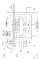
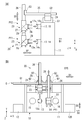
- FIG. 2 is a side view of the work transfer device and the machine tool system shown in FIG. 1.
- FIG. 3 is a diagram illustrating a control unit of the work transfer device by functional blocks.
- FIG. 7 is a diagram illustrating an example of information on a position, a moving direction, and a moving distance of a moving unit, and information on the number, weight, and shape of a work.
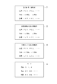
- FIGS. 3A and 3B are diagrams illustrating an example of a data table stored in a control unit.
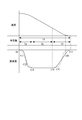
- FIG. 6 is a graph illustrating an example of a curve related to the speed, acceleration or deceleration of a moving unit, and a time constant related to acceleration or deceleration.
- 9 is a graph showing another example of a curve related to the speed, acceleration or deceleration of the moving unit, and a time constant related to acceleration or deceleration.
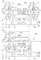
- (A) is a figure showing an example of a position of a movement part
- (B) is a figure showing an example of a movement distance of a movement part.
- (B) is a diagram showing another example of the position of the moving unit, and (B) is a diagram showing an example of the moving direction of the moving unit.
- 5 is a flowchart illustrating an example of a work transfer method according to the embodiment.
- 9 is a flowchart illustrating another example of the work transfer method according to the embodiment.
- a direction perpendicular to the XZ plane is referred to as a Y direction.
- the direction indicated by the arrow in the drawing is the + direction
- the direction opposite to the direction indicated by the arrow is the-direction.
- FIG. 1 is a diagram illustrating an example of a machine tool system SYS according to the present embodiment.
- the machine tool system SYS includes a machine tool 10 and a work transfer device 20 according to the present embodiment.
- the machine tool 10 is, for example, a parallel two-axis lathe, and is arranged with its front side facing in the + Z direction.
- the machine tool 10 has a main body 11, a work supply unit 12A, and a work discharge unit 12B.
- the main body 11 has main shafts 13 and 14, turrets 15 and 16, a reversing device 19, and a device control unit C1.
- the main shafts 13 and 14 are arranged side by side in the X direction.
- the main shafts 13 and 14 are rotatably supported by an unillustrated bearing or the like around an axis parallel to the Z direction.
- Grasp claws 13a, 14a are provided at the + Z side ends of the main shafts 13, 14, respectively.
- a plurality of grasping claws 13a and 14a are arranged at predetermined intervals along the rotation direction of the main shafts 13 and 14.
- the grasping claws 13a and 14a can hold the work W by moving in a radial direction of the main shafts 13 and 14 by a chuck driving unit (not shown).
- the spindles 13 and 14 are destinations of the work W transferred by the work transfer device 20.
- the turrets 15 and 16 are arranged off the axial direction of the main shafts 13 and 14.
- the turret 15 is disposed on the ⁇ X side of the main shaft 13.
- the turret 16 is arranged on the + X side of the main shaft 14.
- Each of the turrets 15 and 16 is provided with a rotary drive device such as a motor.
- the turrets 15 and 16 can be rotated around an axis parallel to the Z direction by a rotary drive device.
- a plurality of holding portions for holding the cutting tool TL are provided on the peripheral surfaces of the turrets 15 and 16.
- a cutting tool TL is held on all or a part of the plurality of holding portions corresponding to the spindles 13 and 14.
- a desired cutting tool TL is selected by rotating the turrets 15 and 16.
- the cutting tool TL held by the holding portions of the turrets 15 and 16 can be exchanged for each holding portion.
- a rotating tool such as a drill or an end mill may be used in addition to a cutting tool for cutting the work W.
- the turrets 15 and 16 can be moved in the X and Z directions by a driving device (not shown).
- the reversing device 19 includes holding parts 17 and 18 capable of holding a work.
- the holding units 17 and 18 are destinations of the work W transferred by the work transfer device 20.
- the holding portions 17 and 18 are arranged in the X direction on the + Y side (upper side) of the main shafts 13 and 14.
- the holding portions 17 and 18 may be rotatably supported around an axis parallel to the Z direction by a bearing (not shown) or the like, or may be in a form that does not rotate.
- Grasp claws 17a, 18a are provided at the + Z side ends of the holding portions 17, 18, respectively.
- a plurality of grasping claws 17a, 18a are arranged at predetermined intervals around the centers of the holding portions 17, 18.
- the grasping claws 17a, 18a can hold the work W by moving in the radial direction of the holding units 17, 18 by a chuck driving unit (not shown).
- the holding section 18 has a slider 18b and a guide member 18c.
- the slider 18b can move along the guide member 18c while holding the holding portion 18.
- the guide member 18c is arranged parallel to the X direction, and guides the slider 18b in the X direction.
- the holding portion 18 can be moved toward and away from the holding portion 17 by the slider 18b and the guide member 18c.
- the work W can be transferred between the holding unit 17 and the holding unit 18 by bringing the holding unit 18 close to the holding unit 17 with the + Z side ends of the holding units 17 and 18 facing each other. I have.
- a workpiece W to be machined by the machine tool 10 is placed on the workpiece supply unit 12A.
- the workpiece supply unit 12A is supplied with the workpiece W transported by the workpiece transport device 20 to the transport destination.
- a fixed table on which the work W is placed may be used, or a configuration for supplying the work by a conveyor or a rotary system may be used.
- the work W processed by the machine tool 10 is placed on the work discharge section 12B.
- the work discharge unit 12 ⁇ / b> B is a transfer destination of the work W by the work transfer device 20.
- As the work discharge unit 12B for example, a fixed base on which the work W is placed may be used, or a configuration for discharging the work by a conveyor or a rotary system may be used.
- the device control unit C1 controls the machine tool 10.
- the device control unit C1 controls, for example, the operations of the spindles 13 and 14, the operations of the turrets 15 and 16, the operations of the holding units 17 and 18 of the reversing device 19, and the like.
- the device control unit C1 may be wirelessly or wiredly connected to, for example, a higher-level controller that integrally controls a plurality of machine tools.
- the work transfer device 20 includes a guide G arranged corresponding to a transfer destination of the work W, a device main body 21, and a control unit C2.
- the guide G has an X guide (first guide) G1, a Z guide (second guide) G2, and a Y guide (third guide) G3.
- the X guide G1 is a rail arranged along the X direction (first direction D1), and guides a traveling body 24 described later in the X direction.
- the Z guide G2 is arranged along the Z direction (second direction D2), and guides the front-rear moving body 25 described later in the Z direction.
- the Y guide G3 is arranged along the Y direction (third direction D3), and guides a later-described lifting rod 26 in the Y direction.
- the apparatus main body 21 has a moving unit 22 and a work holding unit 23.
- the moving unit 22 includes a traveling body 24 as a first moving unit, a front-rear moving body 25 as a second moving unit, and a lifting rod 26 as a third moving unit.
- the traveling body 24 is movable in the first direction D1 (X direction) along the X guide G1 by driving of the traveling body drive unit (first drive unit) M1.
- the traveling body drive unit M1 includes, for example, a drive source (not illustrated) such as an electric motor and a transmission mechanism (not illustrated) that transmits a driving force of the drive source.
- the traveling body driving unit M1 drives the driving source by a current value that is a command from the control unit C2, and moves the traveling body 24 in the + X direction or the ⁇ X direction.
- a Z guide G2 is integrally provided at an end (upper portion) on the + Y side of the traveling body 24.
- the front-rear moving body 25 is movable in the second direction D2 (Z-direction) along the Z guide G2 by driving the front-rear moving body driving unit (second driving unit) M2.
- the front-rear moving body drive unit M2 includes a drive source (not shown) such as an electric motor and a transmission mechanism (not shown) for transmitting the driving force of the drive source.
- the front / rear moving body driving unit M2 drives the driving source by a current value which is a command from the control unit C2, and moves the front / rear moving body 25 in the + Z direction or the ⁇ Z direction.
- a Y guide G3 is integrally provided at the + Z side end of the front-rear moving body 25, a Y guide G3 is integrally provided.
- the lifting rod 26 can be moved up and down (moved) in the third direction D3 (Y direction) along the Y guide G3 by driving the lifting rod driving unit (third driving unit) M3.
- the lifting rod drive unit M3 has a drive source (not shown) such as an electric motor and a transmission mechanism (not shown) that transmits the driving force of the drive source.
- the lifting rod driving unit M3 drives the driving source by a current value which is a command from the control unit C2, and moves the lifting rod 26 upward (moving in the + Y direction) or downward (moving in the -Y direction).
- a work holding portion 23 is provided at the lower end (the end on the ⁇ Y side) of the lifting rod 26.
- the work holding section 23 has a loader head 27.
- the loader head 27 has two loader chucks 28 and 29 that can hold the work W.
- the loader chuck is arranged so as to face the ⁇ Y side (downward).
- the loader chuck 29 is arranged so as to face the ⁇ Z side.
- the loader head 27 has a swivel mechanism rotatable around an axis of a rotation axis AX inclined at 45 ° with respect to the Y axis and the Z axis in the YZ plane.
- the control unit C2 controls the apparatus main body 21.
- the control unit C ⁇ b> 2 controls operations of the traveling body 24, the front-rear moving body 25, the lifting rod 26, and the work holding unit 23.
- FIG. 3 is a functional block diagram illustrating an example of the control unit C2.
- the control unit C2 is driven by the traveling unit driving unit M1, the front-rear moving unit driving unit M2, the lifting rod driving unit M3, and the work holding unit 23, for example, based on a transport command from the device control unit C1 or a higher-level controller.
- the operation of gripping or releasing the work W is controlled.
- the control unit C2 controls the traveling body driving unit M1, the longitudinal moving body driving unit M2, and the lifting rod driving unit M3 so that the traveling body 24, the longitudinal moving body 25, and the elevating rod 26 move to destinations to which the traveling unit 24 should travel.
- the current value is given to the drive source (electric motor or the like).
- the control unit C2 can access the storage unit 50.
- the storage unit 50 may be provided in the control unit C2, may be provided externally to the work transfer device 20 outside the control unit C2, or may be provided in the device control unit C1 of the machine tool 10. May be used.
- the storage unit 50 stores a curve related to the speed, acceleration, or deceleration of the movement of the moving unit 22 (hereinafter, may be referred to as an acceleration curve or a deceleration curve in the present embodiment), and a time constant related to acceleration or deceleration (hereinafter, referred to as “acceleration curve”). In this embodiment, a plurality of acceleration time constants and deceleration time constants may be referred to.).
- the control unit C2 includes an acquisition unit 41, a selection unit 42, a determination unit 43, a predetermined value setting unit 44, and an update unit 45, as shown in FIG.
- the obtaining unit 41 obtains at least one of the position, the moving direction, and the moving distance of the moving unit 22 and at least one of the number, weight, and shape of the work W held by the work holding unit 23.
- the position, the moving direction, and the moving distance of the moving unit 22 can be acquired from the transfer command of the work W sent from the device control unit C1 or the host controller.
- the selection unit 42 is configured to store a plurality of speeds, curves, and time constants related to the movement of the moving unit 22 stored in the storage unit 50 in advance according to at least one of the position, the moving direction, and the moving distance of the moving unit 22. Choose from In addition, the selection unit 42 determines, according to at least one of the position, the movement direction, and the movement distance of the movement unit 22 and at least one of the number, weight, and shape of the work W held by the work holding unit 23. You may choose from multiple speeds, curves, and time constants.
- the determination unit 43 is configured to determine whether the traveling body 22 moves based on the current values (current waveforms) or feedback waveforms of the traveling body driving unit M1, the front-rear moving body driving unit M2, and the lifting rod driving unit M3. It is determined whether or not the loads of the driving unit M1, the front-rear moving body driving unit M2, and the lifting rod driving unit M3 exceed a specified value.
- the predetermined value setting unit 44 sets the load so that the load does not exceed the specified value or reduces the load that exceeds the specified value. Then, the speed, curve, and time constant relating to the movement of the moving unit 22 are set to predetermined values.
- the predetermined value may be selected by the predetermined value setting unit 44 from a plurality of values stored in advance in the storage unit 50 or the like, or may be selected based on a calculation formula stored in advance in the storage unit 50 or the like. 44. Further, the predetermined value may be a value set by an operator. When the predetermined value is set by the predetermined value setting unit 44, the updating unit 45 updates the storage unit 50 with the set predetermined value.
- the update unit 45 may update the speed, the curve, and the time constant of the moving unit 22 to predetermined values in a predetermined order.
- This predetermined order is set in advance for each of the traveling body 24, the front-rear moving body 25, and the elevating rod 26, and may be stored in the storage unit 50 in advance, or the operator may set the predetermined order. Good.
- FIG. 4 is a diagram illustrating an example of information on the position, the moving direction, and the moving distance of the moving unit 22 and information on the number, weight, and shape of the work W by the work holding unit 23.
- the traveling body 24, the front-rear moving body 25, and the elevating rod 26 have information I1, I2, and I3 on their positions, moving directions, and moving distances.
- Such information I1 to I4 are stored in the storage unit 50 in advance.
- the information I1 is the position, the moving direction, and the moving distance of the traveling body 24, and includes positions PX1, PX2, ..., + X direction, -X direction, and distances LX1, LX2, ....
- the position PX1 of the traveling body 24 is, for example, a position corresponding to the work supply unit 12A.
- the position PX2 is a position corresponding to, for example, the main shaft 13 and the holding unit 17.
- the position PX3 is a position corresponding to, for example, the main shaft 14 and the holding unit 18.
- the position PX4 is, for example, a position corresponding to the work discharge unit 12B.
- the + X direction corresponds to, for example, a direction from a position corresponding to the work supply unit 12A to a position corresponding to the main shaft 13, a direction from a position corresponding to the holding unit 17 to a position corresponding to the holding unit 18, or a direction corresponding to the main shaft 14. From the position corresponding to the workpiece discharge unit 12B.
- the -X direction is, for example, a direction from a position corresponding to the work discharge unit 12B to a position corresponding to the work supply unit 12A.
- the distance LX1 is, for example, a distance from a position corresponding to the work supply unit 12A to a position corresponding to the main shaft 13.
- the distance LX2 is, for example, a distance from a position corresponding to the holding unit 17 to a position corresponding to the holding unit 18.
- the distance LX3 is, for example, a distance from a position corresponding to the main shaft 14 to a position corresponding to the work discharge unit 12B.
- the information I2 is the position, the moving direction, and the moving distance of the front-rear moving body 25, and includes positions PZ1, PZ2,..., + Z direction, -Z direction, and distances LZ1, LZ2,.
- the position PZ1 of the front-rear moving body 25 is, for example, a position where the work holding unit 23 corresponds to the work supply unit 12A.
- the position PZ2 is, for example, a position where the work holding unit 23 is opposed to and separated from the main shafts 13 and 14 and the holding units 17 and 18.
- the position PZ3 is, for example, a position at which the work holding unit 23 transfers the work W to the spindles 13 and 14, and the holding units 17 and 18.
- the position PZ4 is, for example, a position where the work holding unit 23 corresponds to the work discharge unit 12B.
- the + Z direction is, for example, a direction from a position where the work holding unit 23 transfers the work W to the main shafts 13 and 14 and the holding units 17 and 18 and a position separated from the main shafts 13 and 14 and the holding units 17 and 18. is there.
- the ⁇ Z direction is, for example, a direction from a position where the work holding unit 23 is separated from the main shafts 13 and 14 and the holding units 17 and 18 to a position where the work W is transferred to the main shafts 13 and 14 and the holding units 17 and 18 and the work W. It is.
- the distance LZ1 is, for example, a distance from a position where the work holding unit 23 is separated from the spindles 13 and 14 and the holding units 17 and 18 to a position where the work W is transferred to the spindles 13 and 14 and the holding units 17 and 18 and the work W. is there.
- the distance LZ2 is, for example, a distance from a position where the work holding unit 23 is separated from the main shaft 13 or the like to a position corresponding to the work supply unit 12A.
- the distance LZ3 is, for example, a distance from a position where the work holding unit 23 is separated from the main shaft 14 or the like to a position corresponding to the work discharge unit 12B.
- the information I3 is the position, the moving direction, and the moving distance of the lifting rod 26, and includes positions PY1, PY2,..., + Y direction, -Y direction, and distances LY1, LY2,.
- the position PY1 of the lifting rod 26 is, for example, a position at which the work holding unit 23 receives the work W from the work supply unit 12A.
- the position PY2 is, for example, a position when the work holding unit 23 moves in the X direction.
- the position PY3 is, for example, a position where the work holding unit 23 corresponds to the main shafts 13 and 14.
- the position PY4 is, for example, a position where the work holding unit 23 corresponds to the holding units 17 and 18.
- the position PY4 is, for example, a position at which the work holding unit 23 transfers the work W to the work discharge unit 12B.
- the + Y direction is an upward direction (upward).
- the + Y direction is, for example, a direction from the position where the work holding unit 23 receives the work W in the work supply unit 12A and the position where the work W is transferred to the work discharge unit 12B to the position where the work W moves in the X direction.
- the direction is from the position corresponding to the main shaft 13 to the position corresponding to the holding unit 17, or the direction from the position corresponding to the main shaft 14 to the position at which the work holding unit 23 moves in the X direction.
- the ⁇ Y direction is a downward direction (downward).
- the ⁇ Y direction is, for example, a direction from a position when the work holding unit 23 moves in the X direction to a position where the work W is received by the work supply unit 12A and a position where the work W is transferred to the work discharge unit 12B. Is a direction from the position at which the workpiece moves in the X direction to a position corresponding to the main shaft 13, or a direction from the position corresponding to the holding portion 18 to the position corresponding to the main shaft 14.
- the distance LY1 is, for example, a distance from a position where the work holding unit 23 receives the work W in the work supply unit 12A and a position where the work W is transferred to the work discharge unit 12B to a position when the work W moves in the X direction.
- the distance LY2 is, for example, a distance from a position where the work holding unit 23 corresponds to the main shafts 13 and 14 to a position corresponding to the holding units 17 and 18.
- the information I4 is information on the number, weight, and shape of the work W by the work W, and includes the numbers 0, 1, 2, weights W1, W2,... And shapes K1, K2,. .
- the number 0 indicates a state where both of the two loader chucks 28 and 29 of the loader head 27 do not hold the work W.
- the number 1 is a situation where only one of the two loader chucks 28 and 29 holds the work W.
- the number 2 is a situation where both of the two loader chucks 28 and 29 are holding the work W.
- the weight W1 is, for example, a light work W.
- the weight W2 is, for example, a heavy workpiece W.
- the shape K1 is, for example, a long object.
- the shape K2 is, for example, a short object.
- FIGS. 5A and 5B are diagrams illustrating an example of a data table stored in the storage unit 50.
- FIG. The data table TB1 in FIG. 5A shows a data table when the traveling body 24 moves.
- the data table TB2 in FIG. 5B shows a data table when the front-rear moving body 25 moves.
- the data tables TB1 and TB2 include information on the position, the moving direction, and the moving distance of the moving unit 22, information on the number, weight, and shape of the work W held by the work holding unit 23, and the speed of the moving unit 22.
- a curve, and a time constant are stored in the storage unit 50 as a data table in which they are associated with each other.
- the data table when the lifting rod 26 is moved is the same as the data tables TB1 and TB2, and illustration and description thereof are omitted.
- the data table TB1 has first areas 111, 121,... For storing information about the traveling body 24, and a second area 112 for storing information about the front-rear moving body 25. , 122,..., Third areas 113, 123,... For storing information about the lifting rod 26, and fourth areas 114, 124 for storing information about the work W held by the work holding unit 23. , And fifth areas 115, 125,... For storing the speed VX1, the curve CX1, and the time constant TX1 of the traveling body 24.
- the data table TB1 indicates that the position of the traveling body 24 is PX1, the moving direction is the + X direction, the moving distance is LX1, the position of the front-rear moving body 25 is PZ1, the position of the lifting rod 26 is PY1, and the work W held by the work holding unit 23.
- the weight is W1
- the shape is K1
- the speed of the traveling body 24 is VX1
- the curve is CX1
- the time constant is TX1.
- the position of the traveling body 24 is PX2, the moving direction is + X direction, the moving distance is LX1, the position of the front and rear moving body 25 is PZ1, the position of the lifting rod 26 is PY1, and the work holding unit 23 holds the data table TB1.
- the weight is W1
- the shape is K1
- the speed of the traveling body 24 is VX2
- the curve is CX2
- the time constant is TX2. I have.
- the data table TB1 is different in any of the position, the moving direction, the moving distance, the position of the front and rear moving body 25, the position of the lifting rod 26, the number, the weight, and the shape of the work W held by the work holding unit 23. Speed, curve, and time constant are set for each.
- the data table TB2 includes first areas 211, 221,... For storing information about the traveling body 24, and a second area 212 for storing information about the front-rear moving body 25. , 222,..., A third area 213, 223,... For storing information about the lifting rod 26, and a fourth area 214, 224 for storing information about the work W held by the work holding unit 23. , And a fifth area 215, 225,... For storing the speed VZ1, the curve CZ1, and the time constant TZ1 of the front-rear moving body 25.
- the data table TB2 indicates that the position of the front-rear moving body 25 is PZ1, the moving direction is + Z direction, the moving distance is LZ1, the position of the traveling body 24 is PX1, the position of the lifting rod 26 is PY1, and the work W held by the work holding unit 23.
- the weight is W1
- the shape is K1
- the speed of the front-rear moving body 25 is VZ1
- the curve is CZ1
- the time constant is TZ1.
- the position of the front-rear moving body 25 is PZ2, the moving direction is + Z direction, the moving distance is LZ1, the position of the traveling body 24 is PX1, the position of the lifting rod 26 is PY1, and the work holding unit 23 holds the data table TB2.
- the weight is W1
- the shape is K1
- the speed of the front-rear moving body 25 is VX2
- the curve is CX2
- the time constant is TX2.
- the data table TB2 is different in any of the position, the moving direction, the moving distance, the position of the traveling body 24, the position of the lifting rod 26, the number, the weight, and the shape of the work W held by the work holding unit 23, of the front-rear moving body 25. Speed, curve, and time constant are set for each.
- the above-mentioned data tables TB1 and TB2 (not shown, but include a data table relating to the lifting rod 26) include the position, the moving direction, the moving distance, and the work holding of the traveling body 24, the front-rear moving body 25, and the lifting rod 26.
- the speed, curve, and time constant are set for each of the different numbers, weights, and shapes of the workpieces W held by the unit 23, the present invention is not limited to this mode.
- a common speed, curve, and time constant may be set even if the position of the traveling body 24 is different.
- the speed, curve, and time constant stored in the data table TB1 and the like are reduced, the data table TB1 and the like stored in the storage unit 50 can be reduced.
- the speed, the curve, and the time constant may be set without using information on the number, weight, and shape of the work W held by the work holding unit 23.
- the data such as the number, the weight, and the shape of the work W may not be stored in the data table TB1 or the like, and the speed, curve, and time constant data corresponding to the change in the data such as the number of the work W are not stored.
- the data table TB1 and the like stored in the unit 50 can be lightened.
- These data tables TB1, TB2, and the like may be obtained in advance by a test operation of transporting the work W by an operator's operation, or may be obtained by using a calculation formula based on an experimental value (simulation) for some or all of the values. Is also good.
- a swing sensor acceleration sensor
- the optimum speed, curve, and time constant are calculated from the detection results from the swing sensor by an arithmetic expression or the like, and the data table TB1 is calculated.
- TB2, etc. may be created.
- the work holding unit 23 does not hold the work W (number 0)
- the maximum speed, the steep curve, the shortest time constant, and the like are set. You may.
- the speed, curve, The time constant may be set.
- These data tables TB1, TB2, etc. can be commonly used in a plurality of work transfer devices 20. In this case, by correcting the data tables TB1, TB2, and the like according to the type and the machine difference of the other work transport devices 20 with respect to the work transport device 20 that has created the reference data tables TB1, TB2, etc.
- the data tables TB1, TB2, etc. can also be used in the work transfer device 20 of FIG.
- FIG. 6 is a graph illustrating an example of the relationship between the speed and curve of the moving unit 22 and the elapsed time.
- FIG. 6 shows a state until the stopped moving unit moves at a predetermined speed.
- the curve in FIG. 6 is an acceleration curve.
- the traveling unit 24 will be described as an example of the moving unit 22, but the same applies to the front-back moving unit 25 or the lifting rod 26.
- the horizontal axis indicates elapsed time
- the vertical axis indicates speed and acceleration, respectively.
- the time constant is shown parallel to the horizontal axis in the graph of FIG.
- the time constant in FIG. 6 is an acceleration time constant.
- the amount of increase in acceleration per unit time gradually increases with time.
- the relationship between the acceleration and the elapsed time is represented as a downwardly convex curve.
- the amount of increase in acceleration per unit time is constant.
- the relationship between the acceleration and the elapsed time is represented as a straight line.
- the amount of increase in acceleration per unit time gradually decreases with time.
- the relationship between the acceleration and the elapsed time is represented as an upwardly convex curve.
- the speed gradually increases with time, and is represented as a downwardly convex curve.
- the acceleration is constant during a period from time t3 to time t4.
- the relationship between the acceleration and the elapsed time is expressed as a straight line parallel to the horizontal axis.
- the speed increases at a constant rate over time, and is represented as a straight line.
- the acceleration decrease period during the period from time t4 to time t5, the amount of decrease in acceleration per unit time gradually increases with time. In this period, the relationship between the acceleration and the elapsed time is represented as an upwardly convex curve. Further, during the period from time t5 to time t6, the amount of decrease in acceleration per unit time is constant. In this period, the relationship between the acceleration and the elapsed time is expressed as a straight line having a negative slope. In addition, during the period from time t6 to time t7, the amount of decrease in acceleration per unit time gradually decreases as time elapses. In this period, the relationship between the acceleration and the elapsed time is represented as a downwardly convex curve. During the acceleration decrease period, the speed gradually decreases with time, and is represented as an upwardly convex curve.
- the relationship between the acceleration and the elapsed time is represented as an acceleration curve.
- the acceleration curve as the seam in the acceleration increasing period, the constant acceleration period, and the acceleration decreasing period becomes smoother than the elapsed time, the speed changes more smoothly, and the swing of the work holding unit 23 is reduced.
- the acceleration time constant T is a time required for the traveling body 24 to reach the target speed.
- the target speed during acceleration may be the maximum speed of the traveling body 24, or may be a speed lower than the maximum speed.
- the acceleration time constant T can be represented by, for example, the sum of a partial time constant Ta in an acceleration increasing period, a partial time constant Tb in a constant acceleration period, and a partial time constant Tc in an acceleration decreasing period.
- the partial time constant Ta set in the acceleration increasing period has a smaller value than the partial time constant Tc set in the acceleration decreasing period. For this reason, the rate of change of the acceleration is greater during the acceleration increase period than during the acceleration decrease period.
- FIG. 7 is a graph showing another example of the relationship between the speed and curve of the moving unit 22 and the elapsed time.
- FIG. 7 shows a state until the moving unit 22 moving at a predetermined speed stops.
- the curve in FIG. 7 is a deceleration curve.
- the traveling unit 24 will be described as an example of the moving unit 22 as in FIG. 6, but the same applies to the front-back moving unit 25 or the lifting rod 26.
- the horizontal axis indicates elapsed time
- the vertical axis indicates speed and acceleration, respectively.
- the time constant is shown parallel to the horizontal axis in the graph of FIG.
- the time constant in FIG. 7 is a deceleration time constant.
- the traveling body 24 (moving unit 22) is traveling at a predetermined speed at time t0, and the speed, deceleration, and deceleration when the traveling body 24 stops (the speed is 0).
- the change of the constant is shown.
- the period in which the deceleration increases (deceleration increase period: from time t0 to time t13)
- the period in which the deceleration is constant (constant deceleration period: from time t13 to time t14)
- the deceleration reduction period from time t14 to time t17).
- the deceleration increasing period in the period from time t0 to time t11, the amount of increase in deceleration per unit time gradually increases with time.
- the relationship between the deceleration and the elapsed time is represented as an upwardly convex curve.
- the amount of increase in deceleration per unit time is constant.
- the relationship between the deceleration and the elapsed time is expressed as a straight line.
- the amount of increase in the deceleration per unit time gradually decreases as time elapses.
- the relationship between the deceleration and the elapsed time is represented as a downwardly convex curve.
- the speed gradually decreases with time, and is represented as an upwardly convex curve.
- the deceleration is constant during a period from time t13 to time t14.
- the relationship between the deceleration and the elapsed time is expressed as a straight line parallel to the horizontal axis.
- the speed decreases at a constant rate over time, and is represented as a straight line.
- the deceleration decrease period in the period from time t14 to time t15, the amount of decrease in deceleration per unit time gradually increases with time.
- the relationship between the deceleration and the elapsed time is represented as a downwardly convex curve.
- the amount of decrease in deceleration per unit time is constant.
- the relationship between the deceleration and the elapsed time is expressed as a straight line.
- the amount of decrease in the deceleration per unit time gradually decreases as time elapses.
- the relationship between the deceleration and the elapsed time is represented as an upwardly convex curve.
- the speed gradually decreases with time and is represented as a downwardly convex curve.
- the relationship between the deceleration and the elapsed time is represented as a deceleration curve.
- the deceleration curve shows that the smoother the seam in the deceleration increasing period, the constant deceleration period, and the deceleration decreasing period, the smoother the change in the speed, and the more the swing of the work holding part 23 is compared with the elapsed time. Less.
- the deceleration time constant T1 is a time until the traveling body 24 stops.
- the target speed at the time of deceleration may be the stop of the traveling body 24 (speed 0) or a predetermined speed lower than the current speed.
- the deceleration time constant T1 can be represented by, for example, the sum of a partial time constant Td during the deceleration increasing period, a partial time constant Te during the constant deceleration period, and a partial time constant Tf during the deceleration decreasing period.
- the partial time constant Td set in the deceleration increasing period has a smaller value than the partial time constant Tf set in the deceleration decreasing period. For this reason, the rate of change of the deceleration is larger during the deceleration increasing period than during the acceleration decreasing period.
- the acceleration curve or the deceleration curve may be different.
- the acceleration curve may be set to be gentler (see the dashed line in FIG. 6) or may be set to be steeper (not shown).
- the acceleration curve may be set to be steeper (see the two-dot chain line in FIG. 6), or the acceleration curve may be set to be more gentle (not shown).
- the deceleration curve may be set to be gentler (see the dashed line in FIG. 7), or the deceleration curve may be set to be steeper. (Not shown).
- the deceleration curve may be set to be steeper (see the two-dot chain line in FIG. 7), or the deceleration curve may be set to be more gentle (see FIG. 7). Not shown).
- the deceleration described above may be represented as a negative acceleration. That is, the deceleration curve may be represented as an acceleration curve, or the deceleration time constant may be represented as a negative acceleration time constant.
- the unprocessed work W previously placed on the work supply unit 12A of the machine tool 10 is held by the work holding unit 23, and the traveling body 24, the front-rear moving body 25 , And the lifting rod 26 is moved to the main shaft 13.
- the work W processed on the main shaft 13 is held by the work holding unit 23 and transported to the holding unit 17 of the reversing device 19.
- the work W is held by the work holding unit 23 and transported to the main shaft 14.
- the work W processed on the main shaft 14 is held by the work holding unit 23 and transported to the work discharge unit 12B.
- the work W after processing is transported to the work discharge unit 12B, but is not limited to this embodiment.
- a transfer device for transferring the processed work W to a work transfer device of another machine tool is provided, and the processed work W is transferred to the transfer device. There may be.
- the control unit C2 determines the position, the moving direction, and the moving distance of the moving unit 22, and At least one of the speed, curve, and time constant of each of the traveling body 24, the front-rear moving body 25, and the lifting rod 26 is set according to the number, weight, and shape of the work W held by the work holding unit 23. Then, the traveling body driving unit M1, the front-rear moving body driving unit M2, or the lifting rod driving unit M3 is controlled.
- FIG. 8A is a diagram illustrating an example of the position of the moving unit 22.
- FIG. 8A shows a position when the traveling body 24 moves in the first direction (X direction) D1 along the X guide G1.
- the work holding unit 23 is provided when the traveling body 24 moves near the main body 11 from the position PX1 and when the traveling body 24 moves away from the main body 11 from the position PX2.
- the swing of the work holding unit 23 is greater when the traveling body 24 moves from the position PX2 than when the traveling body 24 moves from the position PX1. .
- the control unit C2 drives the traveling body so as to reduce the speed (or make the curve gentler or increase the time constant), for example, as compared with the case of moving from the position PX1.
- the unit M1 is controlled.
- the control unit C2 has the same speed, curve, And a time constant, or may be set to a higher speed, a steeper curve, and a smaller time constant than when moving from the position PX1.
- FIG. 8B is a diagram illustrating an example of a moving distance of the moving unit 22.
- FIG. 8B shows the distance when the traveling body 24 moves in the first direction (X direction) D1 along the X guide G1.
- the magnitude of the swing of the work holding unit 23 is different between the case where the traveling body 24 moves the distance LX1 in the first direction D1 and the case where the traveling body 24 moves the distance LX2 larger than the distance LX1.
- the control unit C2 when moving the distance LX1, the control unit C2, for example, reduces the speed (or makes the curve gentler or the time constant larger) than when moving the distance LX2. Control.
- the control unit C2 when moving the distance LX1, when not conveying the work W, or when the swing of the work holding unit 23 can be tolerated, the control unit C2 has the same speed, curve, And a time constant, or may be set to a larger speed, a steeper curve, and a smaller time constant than when moving the distance LX2.
- FIG. 9A is a diagram illustrating an example of the position of the work holding unit 23 (elevation rod 26) when the work holding unit 23 is moved in a direction different from the elevating direction (third direction D3) of the elevating rod 26. It is.
- the lifting rod 26 is at the position PY1, and the work holder 23 is moved by the front-rear moving body 25 from the position facing the main shafts 13 and 14 to the transfer position of the work W in the second direction D2 (third direction).
- the lifting rod 26 In a direction different from D3
- the lifting rod 26 is at the position PY2, and the front-rear moving body 25 is moved in the second direction from the position where the work holding part 23 faces the holding parts 17 and 18 to the transfer position of the work W. D2.
- the vertical rod 26 is at the position PY1 and the front-rear moving body 25 moves in the second direction D2, and the vertical rod 26 is at the position PY2 and the front-rear moving body 25 is
- An example is shown in which the magnitude of the swing of the work holding unit 23 is different between when the workpiece is moved in the second direction D2. That is, when the speed, curve, and time constant of the front-rear moving body 25 are the same, the length from the designated point when the lifting rod 26 is at the position PY1 is longer than when the lifting rod 26 is at the position PY2 ( Since the length from the Y guide G3 to the work holding portion 23) is long, the swing of the work holding portion 23 is increased.
- the control unit C2 moves the forward / backward moving body 25 when the lifting / lowering rod 26 is at the position PY1, for example, compared to the case where the forward / backward moving body 25 moves when the lifting / lowering rod 26 is at the position PY2.
- the front-rear moving body driving unit M2 is controlled so that the speed is reduced (or the curve is gradual or the time constant is increased).
- the control unit C2 operates at the same speed and speed as when moving the front-rear moving body 25 when the lifting rod 26 is at the position PY2. It may be set to a curve and a time constant, or may be set to a larger speed, a steeper curve, and a smaller time constant than when the front-rear moving body 25 is moved when the lifting rod 26 is at the position PY2. .
- FIG. 9B is a diagram illustrating an example of a moving direction of the moving unit 22.
- FIG. 9B shows a case where the lifting rod 26 moves down (moves in the ⁇ Y direction) and a case where it moves up (moves in the + Y direction).
- the magnitude of the swing of the work holding unit 23 is different between the case where the lifting rod 26 moves down and the case where the lifting rod 26 moves up. That is, when the speed, curve, and time constant of the lifting rod 26 are the same, the swing of the work holding unit 23 is greater when the lifting rod 26 is lowered than when the lifting rod 26 is raised.
- the control unit C2 controls the lifting rod driving unit M3 so that, for example, when the lifting rod 26 moves down, the speed is reduced (or the curve is gradual or the time constant is increased) as compared with the case where the lifting rod 26 moves up. I do.
- the control unit C2 operates at the same speed, curve, and time as when the work W is raised. It may be set to a constant, or may be set to a higher speed, a steeper curve, and a smaller time constant than in the case of increasing.
- the acceleration curve and the acceleration time constant after the start of the movement, the movement of the movement unit 22 from the stopped state to the stop at the target position, and the movement of the movement unit 22 are stopped. It is not limited that the deceleration curve and the deceleration time constant before the stop are the same or symmetric.
- the acceleration curve and the deceleration curve may be asymmetric, or the acceleration time constant and the deceleration time constant do not have to be the same value. That is, in a series of operations from the start to the stop of the movement of the moving unit 22, the acceleration curve and the deceleration curve may be set independently, or the acceleration time constant and the deceleration time constant may be set independently. May be done.
- FIG. 10 is a flowchart illustrating an example of the work transfer method according to the present embodiment.
- the control unit C2 acquires at least one of the position, the moving direction, and the moving distance of the moving unit 22 (Step S1).
- the acquisition unit 41 (see FIG. 3) of the control unit C2 is configured to transfer the work W sent from the device control unit C1 of the machine tool 10 or the host controller, or to a position provided in the X guide G1 or the like. From the detection result of the sensor and the like, information of the moving unit 22 regarding the position, the moving direction, the moving distance, and the like of the traveling body 24, the front-rear moving body 25, and the lifting rod 26 is acquired.
- the control unit C2 acquires at least one of the number, weight, and shape of the work W held by the work holding unit 23 (Step S2).
- the acquisition unit 41 of the control unit C2 uses the work holding unit 23 based on the transfer command of the work W or information on the work W sent from the device control unit C1 of the machine tool 10 or the host controller. Information on the number, weight, and shape of the held works W is acquired. Whether or not step S2 is executed is optional, and step S2 may not be executed.
- control unit C2 determines the speed, curve, and speed of the moving unit 22 according to the position, the moving direction, and the moving distance of the moving unit 22 acquired by the acquiring unit 41, and the number, weight, and shape of the work W. At least one of the time constants is controlled (step S3).
- the selecting unit 42 (see FIG. 3) of the control unit C2 stores the position, the moving direction, and the moving distance of the moving unit 22, and the number, weight, and shape of the work W in the storage unit 50.
- the speed, the curve, and the time constant are selected for each of the traveling body 24, the front-rear moving body 25, and the lifting rod 26 from the data tables TB1, TB2 and the like (see FIG. 5).
- step S4 the control unit C2 controls the movement of the moving unit 22 based on the selected speed, curve, and time constant value.
- step S4 the control unit C2 controls the traveling body driving unit M1, the front-rear moving body driving unit M2, or the lifting rod driving unit M3, respectively, so that the speed, the curve, and the time constant selected by the selection unit 42 are obtained.
- the moving unit 22 the traveling body 24, the front-back moving body 25, and the lifting rod 26 moves based on the speed, curve, and time constant set respectively.
- the traveling body 24, the front-rear moving body 25, and the lifting rod 26 are individually moved is described as an example, but the present invention is not limited to this embodiment. Any two or three of the traveling body 24, the front-rear moving body 25, and the lifting rod 26 may be moved at the same time. In this case, the position, the moving direction, and the moving distance of the traveling body 24 and the like, and the number, weight, and shape of the workpiece W are determined for each of the traveling body 24, the front-back moving body 25, and the lifting rod 26 to be moved. Speed, curve, and time constant are set.
- ⁇ Modification> A modification of the present embodiment will be described.
- the control unit C2 controls the traveling body 24, the front-rear moving body 25, and the lifting rod 26 by position sensors (not shown) provided on each of the X guide G1, the Z guide G2, and the Y guide G3.
- the position is detected, and the traveling body driving unit M1, the front-rear moving body driving unit M2, and the lifting rod driving unit M3 are feedback-controlled based on the detection result.
- the control unit C2 transmits the current value (current waveform) or the feedback waveform instructed to the traveling body driving unit M1, the front-rear moving body driving unit M2, and the lifting rod driving unit M3 to the traveling body driving unit M1, the front-rear moving body It is acquired as a load signal given to the driving unit (electric motor) of the driving unit M2 and the lifting rod driving unit M3.
- FIG. 11 is a flowchart illustrating another example of the work transfer method according to the present embodiment.
- FIG. 11 shows the operation after performing step S4.
- the control unit C2 determines a traveling body driving unit from a current value (current waveform) or a feedback waveform given to the traveling body driving unit M1, the front-rear moving body driving unit M2, or the lifting rod driving unit M3.
- the load applied to M1, the moving body driving unit M2, or the lifting rod driving unit M3 is detected (step S5).
- the control unit C2 determines whether or not the detected load exceeds a specified value (Step S6).
- the determination unit 43 see FIG.
- control unit C2 compares the detected load with the specified value stored in the storage unit 50, and determines whether the load applied to the first driving unit M1 or the like is specified. Determine if it exceeds the value.
- the specified value is, for example, a rated value of an electric motor that is a driving source of the first driving unit M1, the second driving unit M2, or the third driving unit M3.
- step S6 the control unit C2 ends the processing illustrated in FIG.
- the control unit C2 determines whether the speed of the traveling body 24, the front-rear moving body 25, or the lifting rod 26 stored in the storage unit 50 is satisfied.
- Curve, and time constant are set to predetermined values (step S7).
- step S7 the predetermined value setting unit 44 of the control unit C2 (see FIG. 3) sets the load of the traveling body driving unit M1, the front-rear moving body driving unit M2, or the lifting rod driving unit M3 not to exceed a specified value.
- at least one of the speed, the curve, and the time constant stored in the storage unit 50 is set to a predetermined value so that the load exceeding the specified value is reduced.
- the predetermined values set by the predetermined value setting unit 44 are a low speed, a gentle curve, and a long time constant with respect to the speed, curve, and time constant set earlier.
- the predetermined value may be selected by the predetermined value setting unit 44 from a plurality of values stored in advance in the storage unit 50 or the like, or may be set based on a calculation formula stored in advance in the storage unit 50 or the like.
- the value calculated by the unit 44 may be used.
- the predetermined value may be a value set by an operator.
- the predetermined value setting unit 44 may significantly reduce the transfer efficiency of the work W if the predetermined value is set so as to eliminate the exceeded portion at a time. In such a case, the predetermined value setting unit 44 sets the predetermined value so that the load exceeding the specified value is reduced as described above, and repeats the setting of the predetermined value, so that the load exceeding the specified value is stepped. The load may eventually be reduced so that the load does not eventually exceed the specified value.
- the predetermined value setting unit 44 may update the speed, the curve, and the time constant to predetermined values in a predetermined order.
- the predetermined value setting unit 44 may set the predetermined value in the order of, for example, speed, time constant, and curve. This order is set, for example, so that the moving time of the moving unit 22 (moving time of the work holding unit 23) does not become long, that is, the transfer efficiency of the work W is not reduced as much as possible.
- a predetermined order may be applied to the storage unit 50, or may be set by an operator.
- the predetermined value setting unit 44 sets the time constant to the predetermined value, for example, when the load still exceeds the specified value during the next movement of the moving unit 22, If the load still exceeds the specified value when the moving unit 22 moves next, the curve is set to a predetermined value, and this processing is repeated until the load falls below the specified value.
- the predetermined order may be a curve or a time constant first.
- control unit C2 updates the value corresponding to the speed stored in the storage unit 50 to the predetermined value set by the predetermined value setting unit 44 (Step S8).
- the updating unit 45 (see FIG. 3) of the control unit C2 sets the speed, curve, and time constant values of the data tables TB1, TB2 and the like stored in the storage unit 50 by the predetermined value setting unit 44. Is updated to the specified value (new value).
- the storage unit 50 may store data such as the speed before the update as an update history.
- control unit C2 determines whether or not the movement of the moving unit 22 has been completed (Step S9).
- step S9 the control unit C2 determines whether or not the movement of the moving unit 22 has been completed based on, for example, a detection result of a position sensor or the like. If the movement of the moving unit 22 has not been completed (NO in step S4), the control unit C2 repeats the processing from step S5. When the movement of the moving unit 22 is completed (YES in step S4), the control unit C2 controls the moving unit 22 to move with the updated predetermined value (step S10).
- the moving unit 22 is moved by the updated fathers from the next movement of the moving unit 22.
- the control unit C2 changes the predetermined value after the movement of the moving unit 22 is completed, and applies the predetermined value in the next movement of the moving unit 22.
- the present invention is not limited to this mode, and may be a mode in which control is performed by switching to a predetermined value while the moving unit 22 is moving.
- the position, the movement direction, and the movement distance of the movement unit 22 and the number, weight, and shape of the work W are controlled by the control unit C2. Accordingly, at least one of the speed, the curve, and the time constant of the moving unit 22 is controlled, so that the moving unit 22 can be optimally moved when the work transfer device 20 is operating. As a result, the work W can be efficiently transported.
- control unit C2 determines the data table stored in the storage unit 50 according to the position, the moving direction, and the moving distance of the moving unit 22 and the number, weight, and shape of the work W.
- the case where the speed, curve, and time constant are selected from TB1, TB2, and the like has been described as an example, but the present invention is not limited to this mode.
- a calculation formula capable of calculating the speed, the curve, and the time constant is stored in the storage unit 50, and the control unit C2 determines the position, the moving direction, and the moving distance of the moving unit 22, the number of the work W,
- the speed, curve, and time constant may be appropriately calculated from the calculation formula according to the weight and the shape.
- the case where the movement of the moving unit 22 is controlled according to at least one of the position, the moving direction, and the moving distance of the moving unit 22 has been described as an example. In addition, other conditions regarding the movement of the moving unit 22 may be added. Further, in the above-described embodiment, the case where the movement of the moving unit 22 is controlled according to at least one of the number, weight, and shape of the work W held by the work holding unit 23 has been described as an example. In addition to these numbers and the like, other conditions regarding the work W may be added.
- At least one of the speed, the curve, and the time constant of the traveling body 24, the front-rear moving body 25, and the lifting rod 26 is controlled in accordance with the position, the moving direction, the moving distance, and the like.
- the control unit C2 may control any one or two of the traveling body 24, the front-rear moving body 25, and the elevating rod 26 according to the position, the moving direction, the moving distance, and the like. Good.
Landscapes
- Engineering & Computer Science (AREA)
- Mechanical Engineering (AREA)
- Robotics (AREA)
- Human Computer Interaction (AREA)
- Manufacturing & Machinery (AREA)
- Physics & Mathematics (AREA)
- General Physics & Mathematics (AREA)
- Automation & Control Theory (AREA)
- Feeding Of Workpieces (AREA)
Abstract
【課題】移動部の移動について最適化を図ることにより、ワークの受け渡し 時などではワーク保持部の揺れを抑えつつ、ワークを効率よく搬送する。 【解決手段】ワーク搬送装置(20)は、搬送先にワークWを搬送するワー ク搬送装置(20)であって、搬送先に対応して配置されるガイドGと、ガ イドGに沿って移動する移動部(22)、及び移動部(22)に設けられてワ ークWを保持するワーク保持部(23)を有する装置本体(21)と、装置 本体(21)を制御する制御部C2と、を備え、制御部C2は、移動部(2 2)の位置、移動方向、及び移動距離のうち少なくとも1つに応じて、移動 部の速度、加速度又は減速度に関するカーブ、及び加速又は減速に関する時 定数のうち少なくとも1つを制御する。
Description
本発明は、ワーク搬送装置、ワーク搬送方法、及び工作機械システムに関する。
工作機械システムにおいて、工作機械の加工領域又は周辺装置などにワークを搬送するワーク搬送装置が知られている。このワーク搬送装置は、搬送先に対応して配置されるガイド(レール)と、ガイドに沿って移動する移動部、及び移動部に設けられてワークを保持するワーク保持部を有する装置本体とを有している。ワーク搬送装置は、ワーク保持部を揺らさずに移動させることが求められる。このため、ワーク保持部が保持するワークの重量に応じて移動部の移動速度を変更可能にしたワーク搬送装置が提案されている(例えば、特許文献1参照)。
特許文献1のワーク搬送装置は、ワーク保持部が保持するワークの重量に応じて移動部の移動速度を変更しているが、ワークを保持しているときだけでなく、ワークを保持していないときも含めて、移動部の移動について最適化を図ることが望まれている。移動部の移動経路には、ワーク保持部によるワークの受け渡し時など、ワーク保持部の揺れを規制すべき場合と、ワーク保持部がワークを保持していないときなど、ワーク保持部の揺れを比較的許容する場合とが混在している。従って、ワーク保持部の揺れを規制すべき場合と、ワーク保持部の揺れを比較的許容する場合とにおいてそれぞれ最適な移動部の移動を実現することにより、ワークの搬送効率を向上させることができると考えられる。
本発明は、移動部の移動について最適化を図ることにより、ワークの受け渡し時などではワーク保持部の揺れを抑えつつ、ワークを効率よく搬送することが可能なワーク搬送装置、ワーク搬送方法、及び工作機械システムを提供することを目的とする。
本発明の態様に係るワーク搬送装置は、搬送先にワークを搬送するワーク搬送装置であって、搬送先に対応して配置されるガイドと、ガイドに沿って移動する移動部、及び移動部に設けられてワークを保持するワーク保持部を有する装置本体と、装置本体を制御する制御部と、を備え、制御部は、移動部の位置、移動方向、及び移動距離のうち少なくとも1つに応じて、移動部の速度、加速度又は減速度に関するカーブ、及び加速又は減速に関する時定数のうち少なくとも1一つを制御する。
また、移動部を移動させる速度、カーブ、及び時定数を記憶する記憶部を備え、制御部は、移動部の位置、移動方向、及び移動距離のうち少なくとも1つに応じて、記憶部に記憶されている複数の速度、カーブ、及び時定数の中から選択してもよい。また、制御部は、ワーク保持部により保持するワークの個数、重量、及び形状のうち少なくとも1つに応じて、移動部の速度、カーブ、及び時定数のうち少なくとも1つを制御してもよい。
また、移動部は、第1方向に移動する第1移動部と、第1方向と直交する第2方向に移動する第2移動部と、第1方向及び第2方向の双方に直交する第3方向に移動しかつワーク保持部が設けられる第3移動部と、を備え、制御部は、第1移動部、第2移動部、及び第3移動部のそれぞれの位置、移動方向、及び移動距離のうち少なくとも1つに応じて、第1移動部、第2移動部、及び第3移動部のそれぞれの速度、カーブ、及び時定数のうち少なくとも1つを制御してもよい。また、制御部は、ガイドに対する第3移動部の位置に応じて、第1移動部及び第2移動部の一方又は双方を移動させる際に、第1移動部及び第2移動部の一方又は双方の速度、カーブ、及び時定数のうち少なくとも1つを制御してもよい。また、第3移動部は、第3方向への移動として昇降可能な昇降ロッドであり、ガイドは、昇降ロッドを昇降可能に保持する第3ガイドを含んでおり、ワーク保持部は、昇降ロッドの下部に設けられてもよい。また、制御部は、移動部が移動する際の負荷が規定値を超える場合、負荷が規定値を超えないように、又は規定値を超える負荷が小さくなるように、移動部の速度、カーブ、及び時定数のうち少なくとも1つを所定値に設定してもよい。また、制御部は、移動部の速度、カーブ、及び時定数を所定の順番で所定値に更新してもよい。
本発明の態様に係るワーク搬送方法は、搬送先に対応して配置されるガイドと、ガイドに沿って移動する移動部、及び移動部に設けられてワークを保持するワーク保持部を有する装置本体と、を備えるワーク搬送装置により搬送先にワークを搬送する方法であって、移動部の位置、移動方向、及び移動距離のうち少なくとも1つに応じて、移動部の速度、加速度又は減速度に関するカーブ、及び加速又は減速に関する時定数の少なくとも一つを制御することを含む。
本発明の態様に係る工作機械システムは、上記のワーク搬送装置と、ワーク搬送装置により搬送されるワークを加工する工作機械と、を備える。
上記したワーク搬送装置及びワーク搬送方法によれば、移動部の位置、移動方向、及び移動距離のうち少なくとも1つに応じて、移動部の速度、カーブ、及び時定数のうち少なくとも1つを制御するため、ワーク搬送装置の稼働時における各状況で移動部の最適な移動を行うことができる。その結果、ワークの受け渡し時などではワーク保持部の揺れを抑えつつ、ワークを効率よく搬送することができる。
また、移動部を移動させる速度、カーブ、及び時定数を記憶する記憶部を備え、制御部が、移動部の位置、移動方向、及び移動距離のうち少なくとも1つに応じて、記憶部に記憶されている複数の速度、カーブ、及び時定数の中から選択する構成では、移動部の移動に関するパラメータである速度、カーブ、及び時定数を容易かつ短時間で設定することができる。また、制御部が、ワーク保持部により保持するワークの個数、重量、及び形状のうち少なくとも1つに応じて、移動部の速度、カーブ、及び時定数のうち少なくとも1つを制御する構成では、ワーク保持部がワークを保持している状況に加味して、移動部の速度等の最適化を図ることができる。
また、移動部が、第1方向に移動する第1移動部と、第1方向と直交する第2方向に移動する第2移動部と、第1方向及び第2方向の双方に直交する第3方向に移動しかつワーク保持部が設けられる第3移動部と、を備え、制御部が、第1移動部、第2移動部、及び第3移動部のそれぞれの位置、移動方向、及び移動距離のうち少なくとも1つに応じて、第1移動部、第2移動部、及び第3移動部のそれぞれの速度、カーブ、及び時定数のうち少なくとも1つを制御する構成では、互いに直交する3軸方向に移動する各移動部において速度等の最適化を図ることができる。また、制御部が、ガイドに対する第3移動部の位置に応じて、第1移動部及び第2移動部の一方又は双方を移動させる際に、第1移動部及び第2移動部の一方又は双方の速度、カーブ、及び時定数のうち少なくとも1つを制御する構成では、ワーク保持部を持つ第3移動部の移動軸とは異なる他の2つの移動軸についても速度等の最適化を図ることができる。また、第3移動部が昇降ロッドであり、ガイドが第3ガイドを含み、ワーク保持部が昇降ロッドの下部に設けられる構成では、昇降ロッドの昇降により第3ガイドからワーク保持部までの長さが変わると、第1移動部又は第2移動部(すなわち、ワーク保持部を持つ昇降ロッドとは異なる移動部)を移動させた際のワーク保持部の揺れが異なるため、昇降ロッドの位置、すなわち第3ガイドに対するワーク保持部の位置に応じて、第1移動部又は第2移動部の速度等を制御することで、ワーク保持部の揺れを抑えつつ、速度等の最適化を図ることができる。また、制御部が、移動部が移動する際の負荷が規定値を超える場合、負荷が規定値を超えないように、又は規定値を超える負荷が小さくなるように、移動部の速度、カーブ、及び時定数のうち少なくとも1つを所定値に設定する構成では、移動部を移動させる際の負荷を低減させ、移動部を安定して移動させることができる。また、制御部が、移動部の速度、カーブ、及び時定数を所定の順番で所定値に更新する構成では、速度等が所定の順番で更新されることにより、移動部を移動させる際の負荷の低減を段階的に行うことができる。
また、上記した工作機械システムによれば、上記したワーク搬送装置と、このワーク搬送装置により搬送されるワークを加工する工作機械と、を備えるので、工作機械に対してワークの搬入及び搬出を効率よく行うことができ、ワークの加工効率(生産効率)を向上させることができる。
以下、本発明の実施形態について図面を参照しながら説明する。ただし、本発明はこの形態に限定されない。また、図面においては実施形態を説明するため、一部分を大きく又は強調して記載するなど適宜縮尺を変更して表現している。以下の各図において、XYZ座標系を用いて図中の方向を説明する。このXYZ座標系においては、水平面に平行な平面をXZ平面とする。このXZ平面において、後述する工作機械10の主軸13、14の回転軸に沿った方向をZ方向と表記し、Z方向に直交する方向をX方向と表記する。また、XZ平面に垂直な方向はY方向と表記する。X方向、Y方向、及びZ方向のそれぞれは、図中の矢印の指す方向が+方向であり、矢印の指す方向とは反対の方向が-方向であるとして説明する。
図1は、本実施形態に係る工作機械システムSYSの一例を示す図である。図1に示すように、工作機械システムSYSは、工作機械10と、本実施形態に係るワーク搬送装置20とを備えている。工作機械10は、例えば平行2軸旋盤であり、+Z方向に正面側を向けて配置される。工作機械10は、本体部11と、ワーク供給部12Aと、ワーク排出部12Bとを有する。
本体部11は、主軸13、14と、タレット15、16と、反転装置19と、装置制御部C1とを有する。主軸13、14は、X方向に並んで配置される。主軸13、14は、不図示の軸受け等によって、Z方向に平行な軸周りに回転可能に支持される。主軸13、14の+Z側の端部には、それぞれ把握爪13a、14aが設けられる。把握爪13a、14aは、主軸13、14の回転方向に沿って所定の間隔で複数配置される。把握爪13a、14aは、不図示のチャック駆動部によって主軸13、14の径方向に移動することでワークWを保持可能である。主軸13、14は、ワーク搬送装置20によるワークWの搬送先である。
タレット15、16は、主軸13、14の軸線方向から外れて配置される。例えば、タレット15は、主軸13の-X側に配置される。タレット16は、主軸14の+X側に配置される。タレット15、16のそれぞれには、モータ等の回転駆動装置が設けられる。タレット15、16は、回転駆動装置により、Z方向に平行な軸周りに回転可能である。タレット15、16の周面には、切削工具TLを保持するための複数の保持部が設けられる。複数の保持部の全部又は一部には、主軸13、14に対応して切削工具TLが保持される。従って、タレット15、16が回転することにより、所望の切削工具TLが選択される。タレット15、16の保持部に保持される切削工具TLは、各保持部に対して交換可能である。切削工具TLとしては、ワークWに対して切削加工を施すバイト等の他、ドリル又はエンドミル等の回転工具が用いられてもよい。また、タレット15、16は、不図示の駆動装置により、X方向及びZ方向に移動可能である。
反転装置19は、ワークを保持可能な保持部17、18を備える。保持部17、18は、ワーク搬送装置20によるワークWの搬送先である。保持部17、18は、主軸13、14の+Y側(上方)において、X方向に並んで配置される。保持部17、18は、不図示の軸受け等によって、Z方向に平行な軸線周りに回転可能に支持されてもよいし、回転しない形態であってもよい。保持部17、18の+Z側の端部には、それぞれ把握爪17a、18aが設けられる。把握爪17a、18aは、保持部17、18の中心の周りに所定の間隔で複数配置される。把握爪17a、18aは、不図示のチャック駆動部によって保持部17、18の径方向に移動することでワークWを保持可能である。
保持部17、18は、それぞれY方向に平行な軸線周りに回転することで、把握爪17a、18aが設けられる側(+Z側)の端部同士を対向させることが可能である。保持部18は、スライダ18b及びガイド部材18cを有する。スライダ18bは、保持部18を保持してガイド部材18c沿って移動可能である。ガイド部材18cは、X方向に平行に配置され、スライダ18bをX方向に案内する。スライダ18b及びガイド部材18cにより、保持部18は保持部17に対して近接及び離間が可能となっている。保持部17、18の+Z側の端部同士が対向した状態で保持部18が保持部17に近接することにより、保持部17と保持部18との間でワークWの受け渡しが可能となっている。
ワーク供給部12Aには、工作機械10における加工対象であるワークWが載置される。ワーク供給部12Aは、ワーク搬送装置20により搬送先に搬送されるワークWが供給される。ワーク供給部12Aとしては、例えば、ワークWを載置する固定台が用いられてもよいし、コンベア又はロータリー式でワークを供給する構成などが用いられてもよい。ワーク排出部12Bには、工作機械10で加工されたワークWが載置される。ワーク排出部12Bは、ワーク搬送装置20によるワークWの搬送先である。ワーク排出部12Bとしては、例えば、ワークWを載置する固定台が用いられてもよいし、コンベア又はロータリー式でワークを排出する構成などが用いられてもよい。
装置制御部C1は、工作機械10を制御する。装置制御部C1は、例えば主軸13、14の動作、タレット15、16の動作、反転装置19の保持部17、18の動作等を制御する。装置制御部C1は、例えば複数台の工作機械を統括して制御する上位コントローラと無線又は有線により接続されていてもよい。
ワーク搬送装置20は、ワークWの搬送先に対応して配置されるガイドGと、装置本体21と、制御部C2とを有する。ガイドGは、Xガイド(第1ガイド)G1、Zガイド(第2ガイド)G2、及びYガイド(第3ガイド)G3を有する。XガイドG1は、X方向(第1方向D1)に沿って配置されるレールであり、後述する走行体24をX方向に案内する。ZガイドG2は、Z方向(第2方向D2)に沿って配置され、後述する前後移動体25をZ方向に案内する。YガイドG3は、Y方向(第3方向D3)に沿って配置され、後述する昇降ロッド26をY方向に案内する。
装置本体21は、移動部22と、ワーク保持部23とを有する。移動部22は、第1移動部としての走行体24と、第2移動部としての前後移動体25と、第3移動部としての昇降ロッド26とを有する。走行体24は、走行体駆動部(第1駆動部)M1の駆動により、XガイドG1に沿って第1方向D1(X方向)に移動可能である。走行体駆動部M1は、例えば、電気モータ等の不図示の駆動源と、駆動源の駆動力を伝達する不図示の伝達機構とを有する。走行体駆動部M1は、制御部C2からの指令である電流値により駆動源を駆動させ、走行体24を+X方向又は-X方向に移動させる。走行体24の+Y側の端部(上部)には、ZガイドG2が一体で設けられる。
前後移動体25は、前後移動体駆動部(第2駆動部)M2の駆動により、ZガイドG2に沿って第2方向D2(Z方向)に移動可能である。前後移動体駆動部M2は、電気モータ等の不図示の駆動源と、駆動源の駆動力を伝達する不図示の伝達機構とを有する。前後移動体駆動部M2は、制御部C2からの指令である電流値により駆動源を駆動させ、前後移動体25を+Z方向又は-Z方向に移動させる。前後移動体25の+Z側端部には、YガイドG3が一体で設けられる。
昇降ロッド26は、昇降ロッド駆動部(第3駆動部)M3の駆動により、YガイドG3に沿って第3方向D3(Y方向)に昇降(移動)可能である。昇降ロッド駆動部M3は、電気モータ等の不図示の駆動源と、駆動源の駆動力を伝達する不図示の伝達機構とを有する。昇降ロッド駆動部M3は、制御部C2からの指令である電流値により駆動源を駆動させ、昇降ロッド26を上昇(+Y方向への移動)又は下降(-Y方向への移動)させる。昇降ロッド26の下端部(-Y側端部)には、ワーク保持部23が設けられる。
ワーク保持部23は、ローダヘッド27を有する。ローダヘッド27は、ワークWを保持可能な2つのローダチャック28、29を有する。ローダチャックは-Y側(下方)に向いた状態で配置されている。ローダチャック29は-Z側に向いた状態で配置されている。ローダヘッド27は、YZ平面内においてY軸及びZ軸に対して45°傾いた回転軸AXの軸周りに回転可能なスイベル機構を有する。
ローダヘッド27が回転軸AXの軸周りに回転することにより、ローダチャック28とローダチャック29との位置関係を変更することができる。ローダチャック28、29により把持されたワークWは、走行体24、前後移動体25、及び昇降ロッド26がそれぞれ移動することにより、X方向(第1方向D1)、Y方向(第3方向D3)、Z方向(第2方向D2)、又はこれら各方向を合成した方向に搬送される。
制御部C2は、装置本体21を制御する。制御部C2は、走行体24、前後移動体25、昇降ロッド26、及びワーク保持部23における動作を制御する。図3は、制御部C2の一例を示す機能ブロック図である。制御部C2は、例えば装置制御部C1又は上位コントローラからの搬送指令に基づいて、走行体駆動部M1、前後移動体駆動部M2、及び昇降ロッド駆動部M3による駆動動作、並びにワーク保持部23によるワークWの把持又は解放の動作を制御する。制御部C2は、走行体24、前後移動体25、及び昇降ロッド26が向かうべき移動先に移動するように、走行体駆動部M1、前後移動体駆動部M2、及び昇降ロッド駆動部M3のそれぞれの駆動源(電気モータ等)に対して電流値を与える。
制御部C2は、記憶部50にアクセス可能である。記憶部50は、制御部C2内に備えていてもよいし、制御部C2外においてワーク搬送装置20に外付けされて設けられてもよいし、工作機械10の装置制御部C1に備える不図示の記憶部が用いられてもよい。記憶部50は、移動部22の移動に関する速度、加速度又は減速度に関するカーブ(以下、本実施形態において加速度カーブ、減速度カーブと称する場合がある。)、及び加速又は減速に関する時定数(以下、本実施形態において加速時定数、減速時定数と称する場合がある。)を複数記憶する。
また、制御部C2は、図3に示すように、取得部41と、選択部42と、判定部43と、所定値設定部44と、更新部45とを有する。取得部41は、移動部22の位置、移動方向、及び移動距離のうち少なくとも1つと、ワーク保持部23により保持するワークWの個数、重量、及び形状のうち少なくとも1つとを取得する。移動部22の位置、移動方向、及び移動距離は、装置制御部C1又は上位コントローラから送られたワークWの搬送指令から取得可能である。
選択部42は、移動部22の位置、移動方向、及び移動距離のうち少なくとも1つに応じて、予め記憶部50に記憶されている移動部22の移動に関する複数の速度、カーブ、及び時定数から選択する。また、選択部42は、移動部22の位置、移動方向、及び移動距離のうち少なくとも1つと、ワーク保持部23により保持するワークWの個数、重量、及び形状のうち少なくとも1つとに応じて、複数の速度、カーブ、及び時定数から選択してもよい。判定部43は、走行体駆動部M1、前後移動体駆動部M2、及び昇降ロッド駆動部M3のそれぞれの電流値(電流波形)又はフィードバック波形に基づいて、移動部22が移動する際の走行体駆動部M1、前後移動体駆動部M2及び昇降ロッド駆動部M3の負荷が規定値を超えるか否かを判定する。
所定値設定部44は、判定部43における判定結果において、負荷が規定値を超えると判定された場合、負荷が規定値を超えない値となるように、又は規定値を超える負荷が小さくなるように、移動部22の移動に関する速度、カーブ、及び時定数を所定値に設定する。所定値は、予め記憶部50等に記憶されている複数の値から所定値設定部44により選択されてもよいし、予め記憶部50等に記憶されている計算式に基づいて所定値設定部44により算出された値であってもよい。また、所定値は、作業者により設定された値であってもよい。更新部45は、所定値設定部44によって所定値が設定された場合、設定された所定値により記憶部50を更新する。更新部45は、移動部22の速度、カーブ、及び時定数を所定の順番で所定値に更新してもよい。この所定の順番は、走行体24、前後移動体25、及び昇降ロッド26のそれぞれについて予め設定され、予め記憶部50に記憶されていてもよいし、作業者が所定の順番を設定してもよい。
図4は、移動部22の位置、移動方向、及び移動距離に関する情報、並びにワーク保持部23によるワークWの個数、重量、及び形状に関する情報の一例を示す図である。走行体24、前後移動体25、及び昇降ロッド26には、図4に示すように、それぞれの位置、移動方向、及び移動距離に関する情報I1、I2、I3がある。また、図4に示すように、ワーク保持部23によるワークWの個数、重量、及び形状に関する情報I4がある。このような情報I1からI4は、予め記憶部50に記憶されている。
情報I1は、走行体24の位置、移動方向、及び移動距離であり、位置PX1、PX2、・・・と、+X方向、-X方向と、距離LX1、LX2、・・・とがある。走行体24の位置PX1は、例えばワーク供給部12Aに対応する位置である。位置PX2は、例えば主軸13及び保持部17に対応する位置である。位置PX3は、例えば主軸14及び保持部18に対応する位置である。位置PX4は、例えばワーク排出部12Bに対応する位置である。
+X方向は、例えば、ワーク供給部12Aに対応する位置から主軸13に対応する位置へ向かう方向、保持部17に対応する位置から保持部18に対応する位置へ向かう方向、又は、主軸14に対応する位置からワーク排出部12Bに対応する位置へ向かう方向である。-X方向は、例えば、ワーク排出部12Bに対応する位置からワーク供給部12Aに対応する位置へ向かう方向である。
距離LX1は、例えば、ワーク供給部12Aに対応する位置から主軸13に対応する位置までの距離である。距離LX2は、例えば、保持部17に対応する位置から保持部18に対応する位置までの距離である。距離LX3は、例えば、主軸14に対応する位置からワーク排出部12Bに対応する位置までの距離である。
情報I2は、前後移動体25の位置、移動方向、及び移動距離であり、位置PZ1、PZ2、・・・と、+Z方向、-Z方向と、距離LZ1、LZ2、・・・とがある。前後移動体25の位置PZ1は、例えば、ワーク保持部23がワーク供給部12Aに対応する位置である。位置PZ2は、例えば、ワーク保持部23が主軸13、14及び保持部17、18に対向して離間した位置である。位置PZ3は、例えば、ワーク保持部23が主軸13、14及び保持部17、18とワークWを受け渡す位置である。位置PZ4は、例えば、ワーク保持部23がワーク排出部12Bに対応する位置である。
+Z方向は、例えば、ワーク保持部23が主軸13、14及び保持部17、18とワークWを受け渡す位置から、主軸13、14及び保持部17、18に対して離間した位置へ向かう方向である。-Z方向は、例えば、ワーク保持部23が主軸13、14及び保持部17、18に対して離間した位置から、主軸13、14及び保持部17、18とワークWを受け渡す位置へ向かう方向である。
距離LZ1は、例えば、ワーク保持部23が主軸13、14及び保持部17、18に対して離間した位置から、主軸13、14及び保持部17、18とワークWを受け渡す位置までの距離である。距離LZ2は、例えば、ワーク保持部23が主軸13等に対して離間した位置からワーク供給部12Aに対応する位置までの距離である。距離LZ3は、例えば、ワーク保持部23が主軸14等に対して離間した位置からワーク排出部12Bに対応する位置までの距離である。
情報I3は、昇降ロッド26の位置、移動方向、及び移動距離であり、位置PY1、PY2、・・・と、+Y方向、-Y方向と、距離LY1、LY2、・・・とがある。昇降ロッド26の位置PY1は、例えば、ワーク保持部23がワーク供給部12AからワークWを受け取る位置である。位置PY2は、例えば、ワーク保持部23がX方向に移動する際の位置である。位置PY3は、例えば、ワーク保持部23が主軸13、14に対応する位置である。位置PY4は、例えば、ワーク保持部23が保持部17、18に対応する位置である。位置PY4は、例えば、ワーク保持部23がワーク排出部12BにワークWを渡す位置である。
+Y方向は、上方に向かう方向(上昇)である。+Y方向は、例えば、ワーク保持部23がワーク供給部12AでワークWを受け取る位置及びワーク排出部12BにワークWを渡す位置からX方向に移動する際の位置へ向かう方向、ワーク保持部23が主軸13に対応する位置から保持部17に対応する位置へ向かう方向、又は、ワーク保持部23が主軸14に対応する位置からX方向に移動する際の位置へ向かう方向である。-Y方向は、下方に向かう方向(下降)である。-Y方向は、例えば、ワーク保持部23がX方向に移動する際の位置からワーク供給部12AでワークWを受け取る位置及びワーク排出部12BにワークWを渡す位置へ向かう方向、ワーク保持部23がX方向に移動する際の位置から主軸13に対応する位置へ向かう方向、又は、ワーク保持部23が保持部18に対応する位置から主軸14に対応する位置へ向かう方向である。
距離LY1は、例えば、ワーク保持部23がワーク供給部12AでワークWを受け取る位置及びワーク排出部12BにワークWを渡す位置からX方向に移動する際の位置までの距離である。距離LY2は、例えば、ワーク保持部23が主軸13、14に対応した位置から保持部17、18に対応する位置までの距離である。
情報I4は、ワークWによるワークWの個数、重量、及び形状に関する情報であり、個数0、1、2と、重量W1、W2、・・・と、形状K1、K2、・・・とがある。個数0は、ローダヘッド27の2つのローダチャック28、29の双方がワークWを保持していない状況である。個数1は、2つのローダチャック28、29のいずれか一方のみがワークWを保持している状況である。個数2は、2つのローダチャック28、29の双方がワークWを保持している状況である。重量W1は、例えば軽いワークWである。重量W2は、例えば重いワークWである。形状K1は、例えば長尺物である。形状K2は、例えば短尺物である。
図5(A)及び(B)は、記憶部50に記憶されるデータテーブルの一例を示す図である。図5(A)のデータテーブルTB1は、走行体24の移動時におけるデータテーブルを示している。図5(B)のデータテーブルTB2は、前後移動体25の移動時におけるデータテーブルを示している。データテーブルTB1、TB2は、移動部22の位置、移動方向、及び移動距離に関する情報、並びにワーク保持部23により保持しているワークWの個数、重量、及び形状に関する情報と、移動部22の速度、カーブ、及び時定数とが対応付けられたデータテーブルとして記憶部50に記憶される。なお、昇降ロッド26の移動時におけるデータテーブルは、データテーブルTB1、TB2と同様であり、図示及びその説明を省略する。
データテーブルTB1は、図5(A)に示すように、走行体24についての情報を記憶する第1領域111、121、・・・と、前後移動体25についての情報を記憶する第2領域112、122、・・・と、昇降ロッド26についての情報を記憶する第3領域113、123、・・・と、ワーク保持部23が保持するワークWについての情報を記憶する第4領域114、124、・・・と、走行体24の速度VX1、カーブCX1、時定数TX1を記憶する第5領域115、125、・・・とを有する。
データテーブルTB1は、走行体24の位置がPX1、移動方向が+X方向、移動距離がLX1、前後移動体25の位置がPZ1、昇降ロッド26の位置がPY1、ワーク保持部23が保持するワークWの個数が0、重量がW1、形状がK1である場合において、第5領域115に示すように、走行体24の速度をVX1、カーブをCX1、時定数をTX1とすることを示している。また、データテーブルTB1は、走行体24の位置がPX2、移動方向が+X方向、移動距離がLX1、前後移動体25の位置がPZ1、昇降ロッド26の位置がPY1、ワーク保持部23が保持するワークWの個数が0、重量がW1、形状がK1である場合において、第5領域125に示すように、走行体24の速度をVX2、カーブをCX2、時定数をTX2とすることを示している。
データテーブルTB1は、走行体24の位置、移動方向、移動距離、前後移動体25の位置、昇降ロッド26の位置、ワーク保持部23が保持するワークWの個数、重量、形状のいずれかが異なるごとに速度、カーブ、時定数が設定されている。
データテーブルTB2は、図5(B)に示すように、走行体24についての情報を記憶する第1領域211、221、・・・と、前後移動体25についての情報を記憶する第2領域212、222、・・・と、昇降ロッド26についての情報を記憶する第3領域213、223、・・・と、ワーク保持部23が保持するワークWについての情報を記憶する第4領域214、224、・・・と、前後移動体25の速度VZ1、カーブCZ1、時定数TZ1を記憶する第5領域215、225、・・・とを有する。
データテーブルTB2は、前後移動体25の位置がPZ1、移動方向が+Z方向、移動距離がLZ1、走行体24の位置がPX1、昇降ロッド26の位置がPY1、ワーク保持部23が保持するワークWの個数が0、重量がW1、形状がK1である場合において、第5領域215に示すように、前後移動体25の速度をVZ1、カーブをCZ1、時定数をTZ1とすることを示している。また、データテーブルTB2は、前後移動体25の位置がPZ2、移動方向が+Z方向、移動距離がLZ1、走行体24の位置がPX1、昇降ロッド26の位置がPY1、ワーク保持部23が保持するワークWの個数が0、重量がW1、形状がK1である場合において、第5領域225に示すように、前後移動体25の速度をVX2、カーブをCX2、時定数をTX2とすることを示している。
データテーブルTB2は、前後移動体25の位置、移動方向、移動距離、走行体24の位置、昇降ロッド26の位置、ワーク保持部23が保持するワークWの個数、重量、形状のいずれかが異なるごとに速度、カーブ、時定数が設定されている。
なお、上記したデータテーブルTB1、TB2(図示していないが、昇降ロッド26に関するデータテーブルを含む)は、走行体24、前後移動体25、昇降ロッド26の位置、移動方向、移動距離、ワーク保持部23が保持するワークWの個数、重量、形状が異なるごとに速度、カーブ、時定数が設定されているが、この形態に限定されない。
例えば、データテーブルTB1等において、走行体24の位置等が異なっても共通の速度、カーブ、時定数が設定されてもよい。この場合、データテーブルTB1等に記憶させる速度、カーブ、時定数が少なくなるので、記憶部50に記憶させておくデータテーブルTB1等を軽くできる。また、例えば、データテーブルTB1等において、ワーク保持部23が保持するワークWの個数、重量、形状の情報を用いずに速度、カーブ、時定数が設定されてもよい。この場合、データテーブルTB1等にワークWの個数、重量、形状のデータがなくてもよく、ワークWの個数等これらのデータの変化に対応した速度、カーブ、時定数のデータもないため、記憶部50に記憶させておくデータテーブルTB1等を軽くできる。
これらデータテーブルTB1、TB2等は、事前にオペレータの操作によってワークWを搬送するテスト稼働により求めてもよいし、一部又は全ての値について実験値(シミュレーション)を元にした計算式により求めてもよい。テスト稼働に際しては、例えば、ワーク保持部23に揺れセンサ(加速度センサ)を搭載させて、この揺れセンサからの検出結果から最適な速度、カーブ、時定数を演算式等により算出してデータテーブルTB1、TB2等を作成してもよい。なお、ワーク保持部23がワークWを保持していない場合(個数0)では、ワーク保持部23の揺れが問題とならないとして、例えば、最大速度、急峻なカーブ、最短の時定数等に設定してもよい。ただし、ワーク保持部23がワークWを保持していないときでも、ワーク保持部23の揺れにより工作機械10の稼働の支障となる場合、稼働時に支障がないような移動部22の速度、カーブ、時定数に設定してもよい。
また、これらデータテーブルTB1、TB2等は、複数のワーク搬送装置20において共通して利用可能である。この場合、基準となるデータテーブルTB1、TB2等を作成したワーク搬送装置20に対して、他のワーク搬送装置20の種類、機差に応じてデータテーブルTB1、TB2等を補正することにより、他のワーク搬送装置20においてもデータテーブルTB1、TB2等を利用可能となる。
ここで、移動部22の速度、カーブ、及び時定数について説明する。図6は、移動部22の速度、及びカーブと、経過時間との関係の一例を示すグラフである。図6は、停止している移動部が所定速度で移動するまでの状態を示している。なお、図6におけるカーブは、加速度カーブである。図6のグラフでは、移動部22として走行体24を例に挙げて説明するが、前後移動体25又は昇降ロッド26においても同様である。なお、図6のグラフは、横軸が経過時間を示しており、縦軸が速度、加速度をそれぞれ示している。時定数は、図6のグラフにおいて、横軸と平行に示している。なお、図6における時定数は、加速時定数である。
図6に示す例では、走行体24(移動部22)が時刻t0で移動を開始し、走行体24の速度が所定速度に到達する場合の速度、加速度、及び加速時定数の変化を示している。この場合において、加速度が増加する期間(加速度増加期間:時刻t0から時刻t3まで)と、加速度が一定の期間(定加速度期間:時刻t3から時刻t4まで)と、加速度が減少する期間(加速度減少期間:時刻t4から時刻t7まで)とが存在する。
加速度増加期間において、時刻t0から時刻t1までの期間では、単位時間当たりの加速度の増加量が時間の経過に伴って徐々に大きくなる。この期間において、加速度と経過時間との関係は、下に凸の曲線として表される。また、時刻t1から時刻t2までの期間では、単位時間当たりの加速度の増加量が一定となる。この期間において、加速度と経過時間との関係は、直線として表される。また、時刻t2から時刻t3までの期間では、単位時間当たりの加速度の増加量が時間の経過に伴って徐々に小さくなる。この期間において、加速度と経過時間との関係は、上に凸の曲線として表される。加速度増加期間において、速度は、時間の経過に伴って徐々に大きくなり、下に凸の曲線として表される。
定加速度期間では、時刻t3から時刻t4までの期間、加速度が一定の状態である。この期間において、加速度と経過時間との関係は、横軸に平行な直線として表される。定加速度期間において、速度は、時間の経過に伴って一定の割合で大きくなり、直線として表される。
加速度減少期間において、時刻t4から時刻t5までの期間では、単位時間当たりの加速度の減少量が時間の経過に伴って徐々に大きくなる。この期間において、加速度と経過時間との関係は、上に凸の曲線として表される。また、時刻t5から時刻t6までの期間では、単位時間当たりの加速度の減少量が一定となる。この期間において、加速度と経過時間との関係は、負の傾きの直線として表される。また、時刻t6から時刻t7までの期間では、単位時間当たりの加速度の減少量が時間の経過に伴って徐々に小さくなる。この期間において、加速度と経過時間との関係は、下に凸の曲線として表される。加速度減少期間において、速度は、時間の経過に伴って徐々に小さくなり、上に凸の曲線として表される。
このように、加速度増加期間、定加速度期間、及び加速度減少期間において、加速度と経過時間との関係は、加速度カーブとして表される。加速度カーブは、経過時間に比して、加速度増加期間、定加速度期間、及び加速度減少期間における継ぎ目が滑らかであるほど、速度の変化が滑らかになり、ワーク保持部23の揺れが少なくなる。
加速時定数Tは、走行体24が目標速度に到達するまでの時間である。加速時定数の値が大きいほど、加速が緩やかになり、加速時定数の値が小さいほど、加速が急激になる。加速時における目標速度は、走行体24の最高速度としてもよいし、最高速度未満の速度としてもよい。
加速時定数Tは、例えば加速度増加期間における部分時定数Taと、定加速度期間における部分時定数Tbと、加速度減少期間における部分時定数Tcとの和で表すことができる。本実施形態において、加速度増加期間に設定される部分時定数Taは、加速度減少期間に設定される部分時定数Tcに比べて、小さい値となっている。このため、加速度増加期間では、加速度減少期間に比べて、加速度の変化率が大きくなっている。
図7は、移動部22の速度、及びカーブと、経過時間との関係の他の例を示すグラフである。図7は、所定速度で移動している移動部22が停止するまでの状態を示している。なお、図7におけるカーブは、減速度カーブである。図7のグラフでは、図6と同様に移動部22として走行体24を例に挙げて説明するが、前後移動体25又は昇降ロッド26においても同様である。なお、図7のグラフは、横軸が経過時間を示しており、縦軸が速度、加速度をそれぞれ示している。時定数は、図7のグラフにおいて、横軸と平行に示している。図7における時定数は、減速時定数である。
図7に示す例では、走行体24(移動部22)が時刻t0で所定の速度で走行しており、走行体24が停止(速度が0)となる場合の速度、減速度、及び減速時定数の変化を示している。この場合において、減速度が増加する期間(減速度増加期間:時刻t0から時刻t13まで)と、減速度が一定の期間(定減速度期間:時刻t13から時刻t14まで)と、減速度が減少する期間(減速度減少期間:時刻t14から時刻t17まで)とが存在する。
減速度増加期間において、時刻t0から時刻t11までの期間では、単位時間当たりの減速度の増加量が時間の経過に伴って徐々に大きくなる。この期間において、減速度と経過時間との関係は、上に凸の曲線として表される。また、時刻t11から時刻t12までの期間では、単位時間当たりの減速度の増加量が一定となる。この期間において、減速度と経過時間との関係は、直線として表される。また、時刻t12から時刻t13までの期間では、単位時間当たりの減速度の増加量が時間の経過に伴って徐々に小さくなる。この期間において、減速度と経過時間との関係は、下に凸の曲線として表される。減速度増加期間において、速度は、時間の経過に伴って徐々に小さくなり、上に凸の曲線として表される。
定減速度期間では、時刻t13から時刻t14までの期間、減速度が一定の状態である。この期間において、減速度と経過時間との関係は、横軸に平行な直線として表される。定減速度期間において、速度は、時間の経過に伴って一定の割合で小さくなり、直線として表される。
減速度減少期間において、時刻t14から時刻t15までの期間では、単位時間当たりの減速度の減少量が時間の経過に伴って徐々に大きくなる。この期間において、減速度と経過時間との関係は、下に凸の曲線として表される。また、時刻t15から時刻t16までの期間では、単位時間当たりの減速度の減少量が一定となる。この期間において、減速度と経過時間との関係は、直線として表される。また、時刻t16から時刻t17までの期間では、単位時間当たりの減速度の減少量が時間の経過に伴って徐々に小さくなる。この期間において、減速度と経過時間との関係は、上に凸の曲線として表される。減速度減少期間において、速度は、時間の経過に伴って徐々に小さくなり、下に凸の曲線として表される。
このように、減速度増加期間、定減速度期間、及び減速度減少期間において、減速度と経過時間との関係は、減速度カーブとして表される。減速度カーブは、経過時間に比して、減速度増加期間、定減速度期間、及び減速度減少期間における継ぎ目が滑らかであるほど、速度の変化が滑らかになり、ワーク保持部23の揺れが少なくなる。
減速時定数T1は、走行体24が停止するまでの時間である。減速時定数の値が大きいほど、減速が緩やかになり、減速時定数の値が小さいほど、減速が急激になる。減速時における目標速度は、走行体24の停止(速度0)としてもよいし、現在の速度より低い所定の速度としてもよい。
減速時定数T1は、例えば減速度増加期間における部分時定数Tdと、定減速度期間における部分時定数Teと、減速度減少期間における部分時定数Tfとの和で表すことができる。本実施形態において、減速度増加期間に設定される部分時定数Tdは、減速度減少期間に設定される部分時定数Tfに比べて、小さい値となっている。このため、減速度増加期間では、加速度減少期間に比べて、減速度の変化率が大きくなっている。
なお、加速時定数又は減速時定数が同一値の場合でも、加速度カーブ又は減速度カーブが異なるように設定することも可能である。例えば、加速度増加期間において、加速度カーブがより緩やかになるように設定してもよいし(図6の一点鎖線参照)、加速度カーブがより急峻になるように設定してもよい(図示省略)。また、加速度減少期間において、加速度カーブがより急峻になるように設定してもよいし(図6の二点鎖線参照)、加速度カーブがより緩やかになるように設定してもよい(図示省略)。また、例えば、減速度増加期間において、減速度カーブがより緩やかになるように設定してもよいし(図7の一点鎖線参照)、減速度カーブがより急峻になるように設定してもよい(図示省略)。また、減速度減少期間において、減速度カーブがより急峻になるように設定してもよいし(図7の二点鎖線参照)、減速度カーブがより緩やかになるように設定してもよい(図示省略)。なお、上記した減速度は、負の加速度として表してもよい。すなわち、減速度カーブは加速度カーブとして表してもよいし、減速時定数を負の加速時定数として表してもよい。
次に、工作機械システムSYSの動作を説明する。まず、ワーク搬送装置20の制御部C2の制御により、工作機械10のワーク供給部12Aに予め載置された未加工のワークWがワーク保持部23により保持され、走行体24、前後移動体25、及び昇降ロッド26が移動することにより主軸13に搬送される。主軸13において加工されたワークWは、ワーク保持部23により保持されて反転装置19の保持部17に搬送される。ワークWが保持部17から保持部18に移載されて反転した後、ワーク保持部23により保持されて主軸14に搬送される。主軸14において加工されたワークWは、ワーク保持部23により保持されてワーク排出部12Bに搬送される。なお、本実施形態では、加工後のワークWをワーク排出部12Bに搬送するが、この形態に限定されない。例えば、XガイドG1の+X側端部に、他の工作機械におけるワーク搬送装置に加工後のワークWを受け渡すための受け渡し装置が設けられ、この受け渡し装置に加工後のワークWを渡す構成であってもよい。
このように、ワーク搬送装置20の移動部22(走行体24、前後移動体25、昇降ロッド26)の各動作において、制御部C2は、移動部22の位置、移動方向、及び移動距離、並びにワーク保持部23に保持されるワークWの個数、重量、及び形状に応じて、走行体24、前後移動体25、又は昇降ロッド26のそれぞれの速度、カーブ、及び時定数の少なくとも一つを設定して、走行体駆動部M1、前後移動体駆動部M2、又は昇降ロッド駆動部M3をそれぞれ制御する。
図8(A)は、移動部22の位置の一例を示す図である。図8(A)では、走行体24がXガイドG1に沿って第1方向(X方向)D1に移動する際の位置について示している。図8(A)に示す例では、走行体24が位置PX1から本体部11の近くを移動する場合と、位置PX2から本体部11に対して離れる方向に移動する場合とで、ワーク保持部23の揺れの大きさが異なる例を示している。つまり、走行体24の速度、カーブ、時定数が同一である場合、走行体24が位置PX1から移動する場合よりも、位置PX2から移動する場合の方が、ワーク保持部23の揺れが大きくなる。
従って、制御部C2は、例えば、位置PX2から移動させる場合に、位置PX1から移動させる場合よりも、例えば、速度を小さく(又はカーブを緩やかに、又は時定数を大きく)するように走行体駆動部M1を制御する。なお、制御部C2は、位置PX2から移動させる場合において、ワークWを搬送しない場合、又はワーク保持部23の揺れを許容可能な場合などでは、位置PX1から移動させる場合と同一の速度、カーブ、及び時定数に設定してもよいし、位置PX1から移動させる場合よりも大きな速度、急峻なカーブ、及び小さな時定数に設定してもよい。特に、位置PX2が本体部11から離れた位置である場合には、ワーク保持部23が揺れても本体部11等への影響が小さいと考えられるので、位置PX1から移動させる場合よりも大きな速度、急峻なカーブ、及び小さな時定数に設定してもよい。
図8(B)は、移動部22の移動距離の例を示す図である。図8(B)では、走行体24がXガイドG1に沿って第1方向(X方向)D1に移動する際の距離について示している。図8(B)に示す例では、走行体24が第1方向D1に距離LX1を移動する場合と、距離LX1よりも大きい距離LX2を移動する場合とで、ワーク保持部23の揺れの大きさが異なる例を示している。つまり、走行体24の速度、カーブ、時定数が同一である場合、移動距離が短くなるほど、ワーク保持部23の揺れが大きくなる。
従って、制御部C2は、距離LX1を移動させる場合に、距離LX2を移動させる場合よりも、例えば、速度を小さく(又はカーブを緩やかに、又は時定数を大きく)するように走行体駆動部M1を制御する。なお、制御部C2は、距離LX1を移動させる場合において、ワークWを搬送しない場合、又はワーク保持部23の揺れを許容可能な場合などでは、距離LX2を移動する場合と同一の速度、カーブ、及び時定数に設定してもよいし、距離LX2を移動させる場合よりも大きな速度、急峻なカーブ、及び小さな時定数に設定してもよい。
図9(A)は、昇降ロッド26の昇降方向(第3方向D3)とは異なる方向にワーク保持部23を移動させる場合について、ワーク保持部23(昇降ロッド26)の位置の例を示す図である。図9(A)では、昇降ロッド26が位置PY1にあり、前後移動体25により、ワーク保持部23が主軸13、14に対向する位置からワークWの受け渡し位置まで第2方向D2(第3方向D3と異なる方向)に移動する場合と、昇降ロッド26が位置PY2にあり、前後移動体25が、ワーク保持部23が保持部17、18に対向する位置からワークWの受け渡し位置まで第2方向D2に移動する場合とを示している。図9(A)に示す例では、昇降ロッド26が位置PY1にあって、前後移動体25が第2方向D2に移動する場合と、昇降ロッド26が位置PY2にあって、前後移動体25が第2方向D2に移動する場合とで、ワーク保持部23の揺れの大きさが異なる例を示している。つまり、前後移動体25の速度、カーブ、時定数が同一である場合、昇降ロッド26が位置PY2にあるときよりも、昇降ロッド26が位置PY1にあるときの方が指示点からの長さ(YガイドG3からワーク保持部23までの長さ)が長くなるので、ワーク保持部23の揺れが大きくなる。
従って、制御部C2は、昇降ロッド26が位置PY1にあるときに前後移動体25を移動させる場合に、昇降ロッド26が位置PY2にあるときに前後移動体25を移動させる場合よりも、例えば、速度を小さく(又はカーブを緩やかに、又は時定数を大きく)するように前後移動体駆動部M2を制御する。なお、制御部C2は、昇降ロッド26が位置PY1にあるときに前後移動体25を移動させる場合に、昇降ロッド26が位置PY2にあるときに前後移動体25を移動させる場合と同一の速度、カーブ、及び時定数に設定してもよいし、昇降ロッド26が位置PY2にあるときに前後移動体25を移動させる場合よりも大きな速度、急峻なカーブ、及び小さな時定数に設定してもよい。
図9(B)は、移動部22の移動方向の例を示す図である。図9(B)では、昇降ロッド26が下降(-Y方向に移動)する場合と、上昇(+Y方向に移動)する場合とを示している。図9(B)に示す例では、昇降ロッド26が下降する場合と、昇降ロッド26が上昇する場合とで、ワーク保持部23の揺れの大きさが異なる例を示している。つまり、昇降ロッド26の速度、カーブ、時定数が同一である場合、昇降ロッド26が下降する場合の方が、昇降ロッド26が上昇する場合よりもワーク保持部23の揺れが大きくなる。
従って、制御部C2は、昇降ロッド26が下降する場合に、上昇する場合よりも、例えば、速度を小さく(又はカーブを緩やかに、又は時定数を大きく)するように昇降ロッド駆動部M3を制御する。なお、制御部C2は、昇降ロッド26が下降する場合において、ワークWを搬送しない場合、又はワーク保持部23の揺れを許容可能な場合などでは、上昇させる場合と同一の速度、カーブ、及び時定数に設定してもよいし、上昇させる場合よりも大きな速度、急峻なカーブ、及び小さな時定数に設定してもよい。
なお、上記した図8及び図9において、移動部22が停止した状態から移動を開始させ、目的の位置に停止させるまでの間において、移動の開始後における加速度カーブ及び加速時定数と、移動の停止前における減速度カーブ及び減速時定数とが同一又は対称となることに限定されない。例えば、加速度カーブと減速度カーブとが非対称であってもよいし、加速時定数と減速時定数とが同一の値とならなくてもよい。すなわち、移動部22の移動開始から停止までの一連の動作において、加速度カーブと減速度カーブとがそれぞれ独立して設定されてもよいし、加速時定数と減速時定数とがそれぞれ独立して設定されてもよい。
図10は、本実施形態に係るワーク搬送方法の一例を示すフローチャートである。図10のフローチャートを説明するに際して、適宜図1から図9の内容を参酌する。図10に示すように、まず、制御部C2は、移動部22の位置、移動方向、及び移動距離のうち少なくとも1つを取得する(ステップS1)。ステップS1において、制御部C2の取得部41(図3参照)は、工作機械10の装置制御部C1又は上位コントローラから送られたワークWの搬送指令、又はXガイドG1等に設けられている位置センサの検出結果などから走行体24、前後移動体25、及び昇降ロッド26の各位置、移動方向、移動距離等に関する移動部22の情報を取得する。
次に、制御部C2は、ワーク保持部23により保持されるワークWの個数、重量、及び形状のうち少なくとも1つを取得する(ステップS2)。ステップS2において、制御部C2の取得部41(図3参照)は、工作機械10の装置制御部C1又は上位コントローラから送られたワークWの搬送指令又はワークWに関する情報などからワーク保持部23により保持されるワークWの個数、重量、及び形状の情報を取得する。なお、ステップS2を実行するか否かは任意であり、ステップS2は実行されなくてもよい。
次に、制御部C2は、取得部41で取得した移動部22の位置、移動方向、及び移動距離、並びにワークWの個数、重量、及び形状に応じて、移動部22の速度、カーブ、及び時定数のうち少なくとも1つを制御する(ステップS3)。ステップS3において、制御部C2の選択部42(図3参照)は、移動部22の位置、移動方向、及び移動距離、並びにワークWの個数、重量、及び形状に応じて、記憶部50に記憶されているデータテーブルTB1、TB2等(図5参照)から走行体24、前後移動体25、又は昇降ロッド26のそれぞれについて、速度、カーブ、及び時定数を選択する。
次に、制御部C2は、選択された速度、カーブ、及び時定数の値に基づいて、移動部22の移動を制御する(ステップS4)。ステップS4において、制御部C2は、選択部42が選択した速度、カーブ、及び時定数となるように走行体駆動部M1、前後移動体駆動部M2、又は昇降ロッド駆動部M3をそれぞれ制御する。このステップS4により、移動部22(走行体24、前後移動体25、昇降ロッド26)は、それぞれに設定された速度、カーブ、及び時定数に基づいて移動することになる。
なお、本実施形態では、走行体24、前後移動体25、及び昇降ロッド26を個別に移動させる場合を例に挙げて説明しているが、この形態に限定されない。走行体24、前後移動体25、及び昇降ロッド26のうちいずれか2つ又は3つを同時に移動させてもよい。この場合、移動させる走行体24、前後移動体25、又は昇降ロッド26のそれぞれに対して、走行体24等の位置、移動方向、及び移動距離、並びにワークWの個数、重量、及び形状に応じて速度、カーブ、及び時定数が設定される。
<変形例>
本実施形態の変形例について説明する。本変形例では、移動部22移動させた際の制御部C2の処理について説明する。図3に示すように、制御部C2は、XガイドG1、ZガイドG2、及びYガイドG3のそれぞれに設けられている不図示の位置センサによって走行体24、前後移動体25、昇降ロッド26の位置を検出し、検出結果に基づいて走行体駆動部M1、前後移動体駆動部M2、及び昇降ロッド駆動部M3をフィードバック制御する。制御部C2は、走行体駆動部M1、前後移動体駆動部M2、及び昇降ロッド駆動部M3に対して指示した電流値(電流波形)又は、フィードバック波形を、走行体駆動部M1、前後移動体駆動部M2、及び昇降ロッド駆動部M3の駆動部(電気モータ)に与えた負荷信号として取得する。
本実施形態の変形例について説明する。本変形例では、移動部22移動させた際の制御部C2の処理について説明する。図3に示すように、制御部C2は、XガイドG1、ZガイドG2、及びYガイドG3のそれぞれに設けられている不図示の位置センサによって走行体24、前後移動体25、昇降ロッド26の位置を検出し、検出結果に基づいて走行体駆動部M1、前後移動体駆動部M2、及び昇降ロッド駆動部M3をフィードバック制御する。制御部C2は、走行体駆動部M1、前後移動体駆動部M2、及び昇降ロッド駆動部M3に対して指示した電流値(電流波形)又は、フィードバック波形を、走行体駆動部M1、前後移動体駆動部M2、及び昇降ロッド駆動部M3の駆動部(電気モータ)に与えた負荷信号として取得する。
図11は、本実施形態に係るワーク搬送方法の他の例を示すフローチャートである。図11では、ステップS4を行った後の動作について示している。図11に示すように、制御部C2は、走行体駆動部M1、前後移動体駆動部M2、又は昇降ロッド駆動部M3に与えている電流値(電流波形)又はフィードバック波形から、走行体駆動部M1、前後移動体駆動部M2、又は昇降ロッド駆動部M3にかかっている負荷を検出する(ステップS5)。制御部C2は、検出した負荷が規定値を超えるか否かを判定する(ステップS6)。ステップS6において、制御部C2の判定部43(図3参照)は、検出した負荷と記憶部50に記憶された規定値とを比較して、第1駆動部M1等にかかっている負荷が規定値を超えるかを判定する。規定値は、例えば、第1駆動部M1、第2駆動部M2、又は第3駆動部M3の駆動源である電気モータの定格値である。
負荷が規定値を超えていないと判定される場合(ステップS6のNO)、制御部C2は、図11に示す処理を終了する。また、負荷が規定値を超えていると判定される場合(ステップS6のYES)、制御部C2は、記憶部50に記憶されている走行体24、前後移動体25、又は昇降ロッド26の速度、カーブ、及び時定数のうち少なくとも1つを所定値に設定する(ステップS7)。ステップS7において、制御部C2の所定値設定部44(図3参照)は、走行体駆動部M1、前後移動体駆動部M2、又は昇降ロッド駆動部M3の負荷が規定値を超えないように、又は規定値を超える負荷が小さくなるように、記憶部50に記憶されている速度、カーブ、及び時定数の少なくとも1つを所定値に設定する。
走行体駆動部M1等の駆動源に対して規定値を超える電流値を与えることを回避する必要がある。そのため、先に設定されている速度等に対して低い速度等となる所定値とすることで、走行体駆動部M1等の駆動源に対して過度な負荷をかけることを防止している。走行体駆動部M1等の駆動源の負荷が規定値を超える要因としては、駆動源又はXガイドG1等のワーク搬送装置20を構成する部材の経年劣化、あるいは搬送するワークWの重量誤差、作業環境の室温変化などがある。所定値設定部44が設定する所定値は、先に設定されている速度、カーブ、及び時定数に対して、低い速度、緩やかなカーブ、長い時定数である。この所定値は、予め記憶部50等に記憶されている複数の値から所定値設定部44により選択されてもよいし、予め記憶部50等に記憶されている計算式に基づいて所定値設定部44により算出された値であってもよい。また、所定値は、作業者により設定された値であってもよい。
また、所定値設定部44は、負荷が規定値を超える場合、超えた部分を一度に解消するような所定値に設定すると、ワークWの搬送効率を大きく低下させる場合がある。このような場合、所定値設定部44は、上記のように、規定値を超える負荷が小さくなるように所定値を設定し、この所定値の設定を繰り返すことにより、規定値を超える負荷が段階的に小さくなるようにして、最終的に負荷が規定値を超えないようにしてもよい。
また、所定値設定部44は、速度、カーブ、及び時定数を所定の順番で所定値に更新してもよい。所定値設定部44は、例えば、速度、時定数、カーブの順で所定値を設定してもよい。この順番は、例えば、移動部22の移動時間(ワーク保持部23の移動時間)が長くならないように、すなわちワークWの搬送効率をできるだけ落とさないように設定される。所定の順番は、記憶部50に予め決められた順番が適用されてもよいし、作業者により設定されてもよい。所定値設定部44は、ステップS7により速度を所定値に設定した後、例えば、次の移動部22の移動時においてまだ負荷が規定値を超えているときには時定数を所定値に設定し、さらに次の移動部22の移動時においてまだ負荷が規定値を超えているときにはカーブを所定値に設定し、この処理を繰り返すことで負荷が規定値を下回るまで繰り返して行う。なお、所定の順番は、最初にカーブ又は時定数であってもよい。
次に、制御部C2は、記憶部50に記憶されている速度当の値を、所定値設定部44により設定された所定値に更新する(ステップS8)。ステップS8において、制御部C2の更新部45(図3参照)は、記憶部50に記憶されるデータテーブルTB1、TB2等の速度、カーブ、及び時定数の値を、所定値設定部44により設定された所定値(新たな値)に更新する。なお、記憶部50には、更新前の速度等のデータを更新履歴として記憶しておいてもよい。
次に、制御部C2は、移動部22の移動が完了したか否かを判定する(ステップS9)。ステップS9において、制御部C2は、例えば、位置センサ等の検出結果から、移動部22の移動が完了したか否かを判断する。移動部22の移動が完了していない場合、(ステップS4のNO)、制御部C2は、ステップS5以降の処理を繰り返して行う。また、移動部22の移動が完了した場合、(ステップS4のYES)、制御部C2は、更新後の所定値で移動部22が移動するように制御する(ステップS10)。この結果、次の移動部22の移動時において、走行体駆動部M1等の駆動源に対する過負荷状態が解消又は軽減され、移動部22を安定して移動させることができる。なお、図11に示すフローチャートでは、次の移動部22の移動から、更新された諸父により移動部22を移動させている。例えば、移動部22の移動途中で速度等を変更すると、その速度等の変化によりワーク保持部23の揺れを招く場合がある。従って、図11に示すフローチャートのように、制御部C2は、移動部22の移動完了後に所定値に変更させ、次の移動部22の移動において所定値を適用するようにしている。ただし、この形態に限定されず、移動部22の移動途中において所定値に切り替えて制御する形態であってもよい。
以上のように、本実施形態に係るワーク搬送装置20及びワーク搬送方法によれば、制御部C2により、移動部22の位置、移動方向、及び移動距離、並びにワークWの個数、重量、及び形状に応じて、移動部22の速度、カーブ、及び時定数の少なくとも一つが制御されるため、ワーク搬送装置20の稼働時において移動部22の最適な移動を行うことができる。その結果、ワークWを効率よく搬送することができる。
以上、実施形態について説明したが、本発明は、上述した説明に限定されず、本発明の要旨を逸脱しない範囲において種々の変更が可能である。例えば、上記した実施形態において、制御部C2は、移動部22の位置、移動方向、及び移動距離、並びにワークWの個数、重量、及び形状に応じて、記憶部50に記憶されているデータテーブルTB1,TB2等の中から速度、カーブ、及び時定数を選択する場合を例に挙げて説明したが、この形態に限定されない。例えば、記憶部50内に速度、カーブ、及び時定数を算出可能な計算式を記憶させておき、制御部C2は、移動部22の位置、移動方向、及び移動距離、並びにワークWの個数、重量、及び形状に応じて、計算式から速度、カーブ、及び時定数を適宜算出してもよい。
また、上記した実施形態では、移動部22の位置、移動方向、及び移動距離のうち少なくとも1つに応じて移動部22の移動を制御する場合を例に挙げて説明したが、これら位置等の他に、移動部22の移動に関する他の条件が加えられてもよい。また、上記した実施形態では、ワーク保持部23により保持されるワークWの個数、重量、及び形状のうち少なくとも1つに応じて移動部22の移動を制御する場合を例に挙げて説明したが、これら個数等の他に、ワークWに関する他の条件が加えられてもよい。
また、上記した実施形態では、走行体24、前後移動体25、及び昇降ロッド26について、それぞれの位置、移動方向、及び移動距離等に応じて速度、カーブ、及び時定数の少なくとも一つを制御する場合を例に挙げて説明したが、この形態に限定されない。例えば、制御部C2は、走行体24、前後移動体25、及び昇降ロッド26のうちいずれか1つ又は2つについて、それぞれの位置、移動方向、及び移動距離等に応じて制御を行ってもよい。
なお、上述の実施形態などで説明した要件の1つ以上は、省略されることがある。また、上述の実施形態などで説明した要件は、適宜組み合わせることができる。また、法令で許容される限りにおいて、日本特許出願である特願2018-187542、及び、上述の実施形態などで引用した全ての文献の開示を援用して本文の記載の一部とする。
D1・・・第1方向
D2・・・第2方向
D3・・・第3方向
G・・・ガイド
G1・・・Xガイド(第1ガイド)
G2・・・Zガイド(第2ガイド)
G3・・・Yガイド(第3ガイド)
M1・・・走行体駆動部(第1駆動部)
M2・・・前後移動体駆動部(第2駆動部)
M3・・・昇降ロッド駆動部(第3駆動部)
TB1、TB2・・・データテーブル
W・・・ワーク
C2・・・制御部
SYS・・・工作機械システム
10・・・工作機械
20・・・ワーク搬送装置
21・・・装置本体
22・・・移動部
23・・・ワーク保持部
24・・・走行体(第1移動部)
25・・・前後移動体(第2移動部)
26・・・昇降ロッド(第3移動部)
41・・・取得部
42・・・選択部
43・・・判定部
44・・・所定値設定部
45・・・更新部
50・・・記憶部
D2・・・第2方向
D3・・・第3方向
G・・・ガイド
G1・・・Xガイド(第1ガイド)
G2・・・Zガイド(第2ガイド)
G3・・・Yガイド(第3ガイド)
M1・・・走行体駆動部(第1駆動部)
M2・・・前後移動体駆動部(第2駆動部)
M3・・・昇降ロッド駆動部(第3駆動部)
TB1、TB2・・・データテーブル
W・・・ワーク
C2・・・制御部
SYS・・・工作機械システム
10・・・工作機械
20・・・ワーク搬送装置
21・・・装置本体
22・・・移動部
23・・・ワーク保持部
24・・・走行体(第1移動部)
25・・・前後移動体(第2移動部)
26・・・昇降ロッド(第3移動部)
41・・・取得部
42・・・選択部
43・・・判定部
44・・・所定値設定部
45・・・更新部
50・・・記憶部
Claims (10)
- 搬送先にワークを搬送するワーク搬送装置であって、
前記搬送先に対応して配置されるガイドと、
前記ガイドに沿って移動する移動部、及び前記移動部に設けられて前記ワークを保持するワーク保持部を有する装置本体と、
前記装置本体を制御する制御部と、を備え、
前記制御部は、前記移動部の位置、移動方向、及び移動距離のうち少なくとも1つに応じて、前記移動部の速度、加速度又は減速度に関するカーブ、及び加速又は減速に関する時定数のうち少なくとも1つを制御する、ワーク搬送装置。 - 前記移動部を移動させる前記速度、前記カーブ、及び前記時定数を記憶する記憶部を備え、
前記制御部は、前記移動部の位置、移動方向、及び移動距離のうち少なくとも1つに応じて、前記記憶部に記憶されている複数の前記速度、前記カーブ、及び前記時定数の中から選択する、請求項1に記載のワーク搬送装置。 - 前記制御部は、前記ワーク保持部により保持する前記ワークの個数、重量、及び形状のうち少なくとも1つに応じて、前記移動部の前記速度、前記カーブ、及び前記時定数のうち少なくとも1つを制御する、請求項1又は請求項2に記載のワーク搬送装置。
- 前記移動部は、第1方向に移動する第1移動部と、前記第1方向と直交する第2方向に移動する第2移動部と、前記第1方向及び前記第2方向の双方に直交する第3方向に移動しかつ前記ワーク保持部が設けられる第3移動部と、を備え、
前記制御部は、前記第1移動部、前記第2移動部、及び前記第3移動部のそれぞれの位置、移動方向、及び移動距離のうち少なくとも1つに応じて、前記第1移動部、前記第2移動部、及び前記第3移動部のそれぞれの前記速度、前記カーブ、及び前記時定数のうち少なくとも1つを制御する、請求項1から請求項3のいずれか一項に記載のワーク搬送装置。 - 前記制御部は、前記ガイドに対する前記第3移動部の位置に応じて、前記第1移動部及び前記第2移動部の一方又は双方を移動させる際に、前記第1移動部及び前記第2移動部の一方又は双方の前記速度、前記カーブ、及び前記時定数のうち少なくとも1つを制御する、請求項4に記載のワーク搬送装置。
- 前記第3移動部は、前記第3方向への移動として昇降可能な昇降ロッドであり、
前記ガイドは、前記昇降ロッドを昇降可能に保持する第3ガイドを含んでおり、
前記ワーク保持部は、前記昇降ロッドの下部に設けられている、請求項5に記載のワーク搬送装置。 - 前記制御部は、前記移動部が移動する際の負荷が規定値を超える場合、前記負荷が前記規定値を超えないように、又は前記規定値を超える前記負荷が小さくなるように、前記移動部の前記速度、前記カーブ、及び前記時定数のうち少なくとも1つを所定値に設定する、請求項1から請求項6のいずれか一項に記載のワーク搬送装置。
- 前記制御部は、前記移動部の前記速度、前記カーブ、及び前記時定数を所定の順番で前記所定値に更新する、請求項7に記載のワーク搬送装置。
- 搬送先に対応して配置されるガイドと、前記ガイドに沿って移動する移動部、及び前記移動部に設けられてワークを保持するワーク保持部を有する装置本体と、を備えるワーク搬送装置により搬送先に前記ワークを搬送する方法であって、
前記移動部の位置、移動方向、及び移動距離のうち少なくとも1つに応じて、前記移動部の速度、加速度又は減速度に関するカーブ、及び加速又は減速に関する時定数のうち少なくとも一つを制御することを含む、ワーク搬送方法。 - 請求項1から請求項8のいずれか一項に記載のワーク搬送装置と、
前記ワーク搬送装置により搬送されるワークを加工する工作機械と、を備える、工作機械システム。
Applications Claiming Priority (2)
| Application Number | Priority Date | Filing Date | Title |
|---|---|---|---|
| JP2018-187542 | 2018-10-02 | ||
| JP2018187542 | 2018-10-02 |
Publications (1)
| Publication Number | Publication Date |
|---|---|
| WO2020070969A1 true WO2020070969A1 (ja) | 2020-04-09 |
Family
ID=70055706
Family Applications (1)
| Application Number | Title | Priority Date | Filing Date |
|---|---|---|---|
| PCT/JP2019/030806 Ceased WO2020070969A1 (ja) | 2018-10-02 | 2019-08-06 | ワーク搬送装置、ワーク搬送方法、及び工作機械システム |
Country Status (1)
| Country | Link |
|---|---|
| WO (1) | WO2020070969A1 (ja) |
Cited By (1)
| Publication number | Priority date | Publication date | Assignee | Title |
|---|---|---|---|---|
| JP7514412B1 (ja) * | 2023-08-30 | 2024-07-10 | ヤマザキマザック株式会社 | 加工システム、工作機械システム、および、ワーク加工方法 |
Citations (9)
| Publication number | Priority date | Publication date | Assignee | Title |
|---|---|---|---|---|
| JPH0212407A (ja) * | 1988-06-30 | 1990-01-17 | Okuma Mach Works Ltd | 数値制御装置 |
| US4997095A (en) * | 1989-04-20 | 1991-03-05 | The United States Of America As Represented By The United States Department Of Energy | Methods of and system for swing damping movement of suspended objects |
| JPH0378006A (ja) * | 1989-08-22 | 1991-04-03 | Fanuc Ltd | 数値制御装置の加減速制御方法 |
| JPH07134607A (ja) * | 1993-11-10 | 1995-05-23 | Enshu Ltd | 最短早送り制御方法 |
| JP2000000732A (ja) * | 1998-06-15 | 2000-01-07 | Murata Mach Ltd | ローダ駆動装置 |
| JP2003236848A (ja) * | 2002-02-15 | 2003-08-26 | Tietech Co Ltd | 部材移動方法及び部材移動装置 |
| JP2004344985A (ja) * | 2003-05-20 | 2004-12-09 | Murata Mach Ltd | 移動体保有機械の制御装置 |
| WO2012057235A1 (ja) * | 2010-10-27 | 2012-05-03 | 株式会社牧野フライス製作所 | 数値制御方法 |
| JP2012108608A (ja) * | 2010-11-15 | 2012-06-07 | Smc Corp | アクチュエータ用駆動制御装置及びアクチュエータの駆動制御方法 |
-
2019
- 2019-08-06 WO PCT/JP2019/030806 patent/WO2020070969A1/ja not_active Ceased
Patent Citations (9)
| Publication number | Priority date | Publication date | Assignee | Title |
|---|---|---|---|---|
| JPH0212407A (ja) * | 1988-06-30 | 1990-01-17 | Okuma Mach Works Ltd | 数値制御装置 |
| US4997095A (en) * | 1989-04-20 | 1991-03-05 | The United States Of America As Represented By The United States Department Of Energy | Methods of and system for swing damping movement of suspended objects |
| JPH0378006A (ja) * | 1989-08-22 | 1991-04-03 | Fanuc Ltd | 数値制御装置の加減速制御方法 |
| JPH07134607A (ja) * | 1993-11-10 | 1995-05-23 | Enshu Ltd | 最短早送り制御方法 |
| JP2000000732A (ja) * | 1998-06-15 | 2000-01-07 | Murata Mach Ltd | ローダ駆動装置 |
| JP2003236848A (ja) * | 2002-02-15 | 2003-08-26 | Tietech Co Ltd | 部材移動方法及び部材移動装置 |
| JP2004344985A (ja) * | 2003-05-20 | 2004-12-09 | Murata Mach Ltd | 移動体保有機械の制御装置 |
| WO2012057235A1 (ja) * | 2010-10-27 | 2012-05-03 | 株式会社牧野フライス製作所 | 数値制御方法 |
| JP2012108608A (ja) * | 2010-11-15 | 2012-06-07 | Smc Corp | アクチュエータ用駆動制御装置及びアクチュエータの駆動制御方法 |
Cited By (3)
| Publication number | Priority date | Publication date | Assignee | Title |
|---|---|---|---|---|
| JP7514412B1 (ja) * | 2023-08-30 | 2024-07-10 | ヤマザキマザック株式会社 | 加工システム、工作機械システム、および、ワーク加工方法 |
| WO2025046787A1 (ja) * | 2023-08-30 | 2025-03-06 | ヤマザキマザック株式会社 | 加工システム、工作機械システム、および、ワーク加工方法 |
| EP4632511A4 (en) * | 2023-08-30 | 2026-03-18 | Yamazaki Mazak Corp | PROCESSING SYSTEM, MACHINE TOOL SYSTEM AND PART PROCESS |
Similar Documents
| Publication | Publication Date | Title |
|---|---|---|
| TWI380940B (zh) | 物品搬運設備及其控制方法 | |
| US8082643B2 (en) | Machining apparatus | |
| JPWO2016047288A1 (ja) | 工作機械システム及びワーク搬送方法 | |
| JP2018039082A (ja) | ロボットシステム | |
| WO2016067457A1 (ja) | 搬送システムおよびその制御方法 | |
| JP6803136B2 (ja) | 工作機械 | |
| WO2020070969A1 (ja) | ワーク搬送装置、ワーク搬送方法、及び工作機械システム | |
| JP7042925B2 (ja) | ワーク自動搬送機 | |
| CN113423533A (zh) | 托盘搬送系统、托盘搬送方法以及托盘搬送程序 | |
| KR20160049418A (ko) | 로봇 시스템을 구비한 씨엔씨 공작기계 | |
| JP2012110997A (ja) | 工作機械システムおよびそのワーク搬送方法 | |
| JP6174193B2 (ja) | 工作機械及び被加工物搬送装置 | |
| CN105228794B (zh) | 工件加工系统 | |
| JP6613080B2 (ja) | 工作機械の搬送装置 | |
| JP7176458B2 (ja) | 自動車部品の製造システムおよび作業機 | |
| JP6469540B2 (ja) | マシニングセンタ | |
| JP6740292B2 (ja) | エアブロー方法および加工システム | |
| JP2013071196A (ja) | ワーク搬送装置 | |
| JP2003175442A (ja) | 工作機械システム | |
| JP6728373B2 (ja) | ワーク自動搬送機 | |
| US9334125B2 (en) | Conveyance system for machining apparatus | |
| JP6154509B2 (ja) | ワーク搬送装置 | |
| JP2005001073A (ja) | 工作機械システムおよびそのワーク搬送方法 | |
| JP5690390B1 (ja) | タレット式木口加工装置及び木材プレカット加工設備 | |
| JPH08174304A (ja) | 多軸旋盤システム及びワーク搬送方法 |
Legal Events
| Date | Code | Title | Description |
|---|---|---|---|
| 121 | Ep: the epo has been informed by wipo that ep was designated in this application |
Ref document number: 19868286 Country of ref document: EP Kind code of ref document: A1 |
|
| NENP | Non-entry into the national phase |
Ref country code: DE |
|
| 122 | Ep: pct application non-entry in european phase |
Ref document number: 19868286 Country of ref document: EP Kind code of ref document: A1 |
|
| NENP | Non-entry into the national phase |
Ref country code: JP |