WO2020070804A1 - 故障診断システム - Google Patents
故障診断システムInfo
- Publication number
- WO2020070804A1 WO2020070804A1 PCT/JP2018/036889 JP2018036889W WO2020070804A1 WO 2020070804 A1 WO2020070804 A1 WO 2020070804A1 JP 2018036889 W JP2018036889 W JP 2018036889W WO 2020070804 A1 WO2020070804 A1 WO 2020070804A1
- Authority
- WO
- WIPO (PCT)
- Prior art keywords
- contact
- state
- main contact
- power line
- control
- Prior art date
- Legal status (The legal status is an assumption and is not a legal conclusion. Google has not performed a legal analysis and makes no representation as to the accuracy of the status listed.)
- Ceased
Links
Images


Classifications
-
- H—ELECTRICITY
- H02—GENERATION; CONVERSION OR DISTRIBUTION OF ELECTRIC POWER
- H02J—ELECTRIC POWER NETWORKS; CIRCUIT ARRANGEMENTS OR SYSTEMS FOR SUPPLYING OR DISTRIBUTING ELECTRIC POWER; SYSTEMS FOR STORING ELECTRIC ENERGY
- H02J1/00—Circuit arrangements for DC mains or DC distribution networks
- H02J1/06—Two-wire DC power distribution systems
-
- H—ELECTRICITY
- H02—GENERATION; CONVERSION OR DISTRIBUTION OF ELECTRIC POWER
- H02H—EMERGENCY PROTECTIVE CIRCUIT ARRANGEMENTS
- H02H7/00—Emergency protective circuit arrangements specially adapted for specific types of electric machines or apparatus or for sectionalised protection of cable or line systems, and effecting automatic switching in the event of an undesired change from normal working conditions
- H02H7/22—Emergency protective circuit arrangements specially adapted for specific types of electric machines or apparatus or for sectionalised protection of cable or line systems, and effecting automatic switching in the event of an undesired change from normal working conditions for distribution gear, e.g. bus-bar systems; for switching devices
- H02H7/222—Emergency protective circuit arrangements specially adapted for specific types of electric machines or apparatus or for sectionalised protection of cable or line systems, and effecting automatic switching in the event of an undesired change from normal working conditions for distribution gear, e.g. bus-bar systems; for switching devices for switches
-
- H—ELECTRICITY
- H02—GENERATION; CONVERSION OR DISTRIBUTION OF ELECTRIC POWER
- H02H—EMERGENCY PROTECTIVE CIRCUIT ARRANGEMENTS
- H02H7/00—Emergency protective circuit arrangements specially adapted for specific types of electric machines or apparatus or for sectionalised protection of cable or line systems, and effecting automatic switching in the event of an undesired change from normal working conditions
- H02H7/10—Emergency protective circuit arrangements specially adapted for specific types of electric machines or apparatus or for sectionalised protection of cable or line systems, and effecting automatic switching in the event of an undesired change from normal working conditions for converters; for rectifiers
- H02H7/12—Emergency protective circuit arrangements specially adapted for specific types of electric machines or apparatus or for sectionalised protection of cable or line systems, and effecting automatic switching in the event of an undesired change from normal working conditions for converters; for rectifiers for static converters or rectifiers
- H02H7/125—Emergency protective circuit arrangements specially adapted for specific types of electric machines or apparatus or for sectionalised protection of cable or line systems, and effecting automatic switching in the event of an undesired change from normal working conditions for converters; for rectifiers for static converters or rectifiers for rectifiers
- H02H7/1255—Emergency protective circuit arrangements specially adapted for specific types of electric machines or apparatus or for sectionalised protection of cable or line systems, and effecting automatic switching in the event of an undesired change from normal working conditions for converters; for rectifiers for static converters or rectifiers for rectifiers responsive to internal faults, e.g. by monitoring ripple in output voltage
-
- H—ELECTRICITY
- H02—GENERATION; CONVERSION OR DISTRIBUTION OF ELECTRIC POWER
- H02H—EMERGENCY PROTECTIVE CIRCUIT ARRANGEMENTS
- H02H7/00—Emergency protective circuit arrangements specially adapted for specific types of electric machines or apparatus or for sectionalised protection of cable or line systems, and effecting automatic switching in the event of an undesired change from normal working conditions
- H02H7/20—Emergency protective circuit arrangements specially adapted for specific types of electric machines or apparatus or for sectionalised protection of cable or line systems, and effecting automatic switching in the event of an undesired change from normal working conditions for electronic equipment
Definitions
- the embodiment of the present invention relates to a failure diagnosis system.
- the problem to be solved by the present invention is to provide a failure diagnosis system that can increase the reliability of failure diagnosis.
- the failure diagnosis system includes a first power line, a second power line, a first main contact, a second main contact, a first electric component, a second electric component, and a control device.
- the first power line includes a first portion electrically connected to a power supply, and a second portion electrically connected to a load.
- the second power line includes a third portion electrically connected to the power supply, and a fourth portion electrically connected to the load.
- the first main contact is provided between a first portion and a second portion of the first power line.
- the second main contact is provided between a third portion and a fourth portion of the second power line.
- the first electric component has a first terminal electrically connected to a second portion of the first power line, and a second terminal electrically connected to a third portion of the second power line, The state changes when a voltage is applied between the first terminal and the second terminal.
- the second electrical component has a third terminal electrically connected to a first portion of the first power line, and a fourth terminal electrically connected to a fourth portion of the second power line, The state changes when a voltage is applied between the third terminal and the fourth terminal.
- the control device determines whether there is an abnormality in the first main contact based on an output of a first control command relating to the first main contact and a state of the first electrical component, and determines whether there is an abnormality in the second main contact. (2) Based on the output of the control command and the state of the second electric component, it is determined whether or not the second main contact is abnormal.
- FIG. 1 is a configuration diagram illustrating a failure diagnosis system according to an embodiment.
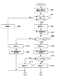
- 5 is a flowchart illustrating a part of an example of a flow of a failure diagnosis operation according to the embodiment.
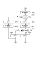
- 5 is a flowchart illustrating a part of an example of a flow of a failure diagnosis operation according to the embodiment.
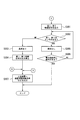
- 5 is a flowchart illustrating a part of an example of a flow of a failure diagnosis operation according to the embodiment.
- FIG. 9 is a configuration diagram illustrating a failure diagnosis system according to a modification of the embodiment.
- based on XX means “based at least on XX”, and includes cases based on another element in addition to XX. Further, “based on XX” is not limited to the case where XX is used directly, but also includes the case where XX is calculated or processed. “XX” is an arbitrary element (for example, arbitrary information).
- connection in this specification is not limited to the case where the connection is made physically, but also includes the case where the connection is made electrically.
- line (for example, a “line” such as a power line or a connection line) does not mean a linearly extending object, and is a conductor through which a current formed by one or more conductors flows. Part means broadly. As used herein, "midway of XX” does not mean an intermediate point between both ends of XX, but means any position in XX.
- FIG. 1 is a configuration diagram illustrating a failure diagnosis system 1.
- the failure diagnosis system 1 of the present embodiment is, for example, a system that diagnoses whether or not two main contacts 111 and 121 provided between the power supply PS and the load L are abnormal.
- the load L is, for example, a brake unit in a motor drive system.
- the brake unit releases the brake in an excited state, for example, and applies the brake when power is lost (when not excited).
- the brake unit is an example of a “stop device” and safely stops the device when power supply from the power supply PS is cut off.
- the load L is not limited to the brake unit, and may be a device having a function other than the brake.
- the failure diagnosis system 1 includes first and second power lines 11 and 12, first to fourth connection lines 21, 22, 23 and 24, and first and second power lines 11 and 22.
- the first and second power lines 11 and 12 are provided between the power supply PS and the load L. More specifically, one end of the first power line 11 is connected to the first terminal PSa of the power supply PS. The other end of the first power line 11 is connected to a first terminal La of the load L. On the other hand, one end of the second power line 12 is connected to the second terminal PSb of the power supply PS. The other end of the second power line 12 is connected to a second terminal Lb of the load L.
- the first and second power lines 11 and 12 are electrically provided in parallel with each other, and currents flowing in directions opposite to each other flow. The first and second power lines 11 and 12 form a main circuit that supplies power from the power supply PS to the load L.
- the power supplied from the power supply PS to the load L via the first and second power lines 11 and 12 may be DC power or AC power.
- the load L is a brake unit and is mechanically connected to a rotating shaft of an electric motor (not shown).
- the brake is released and the electric motor can rotate.
- the load L cuts off the supply of power through the first and second power lines 11 and 12, the load L will brake the motor.
- the brake unit has a so-called fail-safe configuration in which the brake operates when a failure such as a power failure occurs.
- the first power line 11 has a first portion 11a connected to the first terminal PSa of the power supply PS, and a second portion 11b connected to the first terminal La of the load L.
- a first main contact 111 (described later) included in the first contactor 110 is provided between the first portion 11a and the second portion 11b.
- the second power line 12 has a third portion 12a connected to the second terminal PSb of the power supply PS and a fourth portion 12b connected to the second terminal Lb of the load L.
- a second main contact 121 (described later) included in the second contactor 120 is provided between the third portion 12a and the fourth portion 12b.
- the first connection line 21 is provided between the second portion 11b of the first power line 11 and the third portion 12a of the second power line 12. Specifically, the first connection line 21 has a first portion 21a connected to the second portion 11b of the first power line 11 and a second portion 21b connected to the third portion 12a of the second power line 12. .
- a first coil 311 (described later) included in the first diagnostic relay 310 is provided between the first portion 21a and the second portion 21b.
- the second connection line 22 is provided between the first portion 11a of the first power line 11 and the fourth portion 12b of the second power line 12. Specifically, the second connection line 22 has a first portion 22a connected to the first portion 11a of the first power line 11 and a second portion 22b connected to the fourth portion 12b of the second power line 12. .
- a second coil 321 (described later) included in the second diagnostic relay 320 is provided between the first portion 22a and the second portion 22b.
- the third connection line 23 is provided between the first portion 11a of the first power line 11 and the third portion 12a of the second power line 12.
- the third connection line 23 has a first portion 23a, a second portion 23b, and a third portion 23c.
- the first portion 23a is connected to the first portion 11a of the first power line 11.
- the second portion 23b is connected to the third portion 12a of the second power line 12.
- the third portion 23c is located between the first portion 23a and the second portion 23b.
- a third contact 412 (described later) included in the first control relay 410 is provided between the first portion 23a and the third portion 23c.
- a first main coil 112 (described later) included in the first contactor 110 is provided between the third portion 23c and the second portion 23b. Note that the arrangement of the third contact 412 and the first main coil 112 may be opposite to each other.
- the fourth connection line 24 is provided between the first portion 11a of the first power line 11 and the third portion 12a of the second power line 12, similarly to the third connection line 23.
- the fourth connection line 24 is provided electrically in parallel with the third connection line 23.
- the fourth connection line 24 has a first portion 24a, a second portion 24b, and a third portion 24c.
- the first portion 24a is connected to the first portion 11a of the first power line 11.
- the second portion 24b is connected to the third portion 12a of the second power line 12.
- the third portion 24c is located between the first portion 24a and the second portion 24b.
- a fourth contact 422 (described later) included in the second control relay 420 is provided between the first portion 24a and the third portion 24c.
- a second main coil 122 (described later) included in the second contactor 120 is provided between the third portion 24c and the second portion 24b. The arrangement of the fourth contact 422 and the second main coil 122 may be reversed.
- First contactor 110 includes a first main contact 111 and a first main coil 112.
- the first main contact 111 is a make contact (so-called “a contact”) corresponding to the first main coil 112, and is in an open state (non-conductive state) when the first main coil 112 is not energized. When the coil 112 is excited, it is in a closed state (conductive state).
- the first main contact 111 is provided between the first part 11a and the second part 11b of the first power line 11, and switches a conduction state between the first part 11a and the second part 11b. For example, when the first main contact 111 is operated in a closed state, the first power line 11 is brought into a conductive state between the first portion 11a and the second portion 11b.
- the power supply PS and the load L are electrically connected via the first power line 11.
- the first main contact 111 by operating the first main contact 111 in the open state, the first power line 11 is brought into a non-conductive state between the first portion 11a and the second portion 11b. In this case, the electrical connection between the power supply PS and the load L by the first power line 11 is cut off.
- the first main coil 112 is provided in the middle of the third connection line 23, and is excited when the third contact 412 is switched to a closed state (conductive state).
- Second contactor 120 includes a second main contact 121 and a second main coil 122.
- the second main contact 121 is a make contact corresponding to the second main coil 122, is in an open state (non-conductive state) when the second main coil 122 is not excited, and the second main coil 122 is excited. At this time, it is closed (conductive state).
- the second main contact 121 is provided between the third portion 12a and the fourth portion 12b of the second power line 12, and switches a conduction state between the third portion 12a and the fourth portion 12b. For example, by operating the second main contact 121 in the closed state, the second power line 12 is brought into a conductive state between the third portion 12a and the fourth portion 12b of the second power line 12.
- the power supply PS and the load L are electrically connected via the second power line 12.
- the second main contact 121 by operating the second main contact 121 in the open state, the second power line 12 is brought into a non-conductive state between the third portion 12a and the fourth portion 12b of the second power line 12. In this case, the electrical connection between the power supply PS and the load L by the second power line 12 is cut off.
- the second main coil 122 is provided in the middle of the fourth connection line 24, and is excited when the fourth contact 422 is switched to a closed state (conductive state).
- the first control circuit 210 includes first to third control lines 211, 212, and 213.
- the first control line 211 has a first portion 211a, a second portion 211b, and a third portion 211c.
- the first portion 211a is connected to the first control power line PL1 outside the control device 500, for example.
- the third portion 211c is connected to the second control power line PL2 outside the control device 500, for example.
- the first control power line PL1 and the second control power line PL2 are paired power lines.
- the second part 211b is located between the first part 211a and the third part 211c.
- a third coil 411 (described later) included in the first control relay 410 is provided between the first portion 211a and the second portion 211b.
- a first internal contact 511 (described later) included in the control device 500 is provided between the second part 211b and the third part 211c.
- the second control line 212 has a first portion 212a and a second portion 212b.
- the first portion 212a is connected to the first portion 211a of the first control line 211, and is connected to the first control power line PL1 via the first portion 211a of the first control line 211.
- the first portion 212a may be directly connected to the first control power line PL1 instead of the first portion 211a of the first control line 211, or may be connected to another control power line.
- the second portion 212b is connected to a first terminal 521a of a first detection circuit 521 (described later) included in the control device 500.
- a first contact 312 (described later) included in the first diagnostic relay 310 is provided between the first portion 212a and the second portion 212b.
- One end of the third control line 213 is connected to the second terminal 521b of the first detection circuit 521 included in the control device 500.
- the other end of the third control line 213 is connected to the third portion 211c of the first control line 211, and is connected to the second control power line PL2 via the third portion 211c of the first control line 211.
- the third control line 213 may be directly connected to the second control power line PL2 instead of the third portion 211c of the second control line 212, or may be connected to another control power line. Is also good.
- the second control circuit 220 includes fourth to sixth control lines 221, 222, and 223.
- the fourth control line 221 has a first portion 221a, a second portion 221b, and a third portion 221c.
- the first portion 221a is connected to the first control power line PL1 outside the control device 500, for example.
- the first portion 221a may be connected to another control power line instead of the first control power line PL1.
- the third portion 221c is connected to the second control power line PL2 outside the control device 500, for example.
- the third portion 221c may be connected to another control power line instead of the second control power line PL2.
- the second part 221b is located between the first part 221a and the third part 221c.
- a fourth coil 421 (described later) included in the second control relay 420 is provided between the first portion 221a and the second portion 221b.
- a second internal contact 512 (described later) included in the control device 500 is provided between the second part 221b and the third part 221c.
- the fifth control line 222 has a first portion 222a and a second portion 222b.
- the first portion 222a is connected to the first portion 221a of the fourth control line 221 and is connected to the first control power line PL1 via the first portion 221a of the fourth control line 221.
- the fifth control line 222 may be directly connected to the first control power line PL1 instead of the first portion 221a of the fourth control line 221 or may be connected to another control power line.
- the second portion 222b is connected to a first terminal 522a of a second detection circuit 522 (described later) included in the control device 500.
- a second contact 322 (described later) included in the second diagnostic relay 320 is provided between the first portion 222a and the second portion 222b.
- One end of the sixth control line 223 is connected to the second terminal 522b of the second detection circuit 522 included in the control device 500.
- the other end of the sixth control line 223 is connected to the third portion 221c of the fourth control line 221 and is connected to the second control power line PL2 via the third portion 221c of the fourth control line 221.
- the sixth control line 223 may be directly connected to the second control power line PL2 instead of the third portion 221c of the fourth control line 221, or may be connected to another control power line. Is also good.
- the first diagnostic relay 310 includes a first coil 311 and a first contact 312.
- the first coil 311 has a first terminal 311a and a second terminal 311b.
- the first terminal 311a is connected to the first portion 21a of the first connection line 21, and is electrically connected to the second portion 11b of the first power line 11 via the first portion 21a.
- the second terminal 311b is connected to the second portion 21b of the first connection line 21, and is electrically connected to the third portion 12a of the second power line 12 via the second portion 21b.
- the first coil 311 is excited when the first main contact 111 is closed and a voltage is applied between the first terminal 311a and the second terminal 311b, and switches the state of the first contact 312.
- the first contact 312 is a make contact corresponding to the first coil 311.
- the first contact 312 is in an open state (non-conductive state) when the first coil 311 is not excited, and is in a closed state when the first coil 311 is excited ( Conduction state).
- the first contact 312 By operating the first contact 312 to be in the closed state, the first contact 312 establishes a conductive state between the first portion 212a and the second portion 212b of the second control line 212.
- the first control power line PL1 and the first terminal 521a of the first detection circuit 521 are electrically connected via the first and second control lines 211 and 212. As a result, a current is input to the first terminal 521a of the first detection circuit 521.
- the first contact 312 by operating the first contact 312 in the open state, the first contact 212a and the second part 212b of the second control line 212 are brought into a non-conductive state. In this case, the electrical connection between the first control power line PL1 and the first terminal 521a of the first detection circuit 521 is cut off.
- the first diagnostic relay 310 is an example of each of the “first electric component” and the “first relay”.
- the open / closed state of the first contact 312 is an example of “the state of the first electric component”.
- the second diagnostic relay 320 includes a second coil 321 and a second contact 322.
- the second coil 321 has a third terminal 321a and a fourth terminal 321b.
- the third terminal 321a is connected to the first portion 22a of the second connection line 22, and is electrically connected to the first portion 11a of the first power line 11 via the first portion 22a.
- the fourth terminal 321b is connected to the second portion 22b of the second connection line 22, and is electrically connected to the fourth portion 12b of the second power line 12 via the second portion 22b.
- the second coil 321 is excited when the second main contact 121 is closed and a voltage is applied between the third terminal 321a and the fourth terminal 321b, and switches the state of the second contact 322.
- the second contact 322 is a make contact corresponding to the second coil 321.
- the second contact 322 is in an open state (non-conductive state) when the second coil 321 is not excited, and is closed when the second coil 321 is excited ( Conduction state).
- the second contact 322 is provided between the first part 222a and the second part 222b of the fifth control line 222, and switches the conduction state between the first part 222a and the second part 222b. For example, by operating the second contact 322 in the closed state, the second control part 222 makes the first part 222a and the second part 222b of the fifth control line 222 conductive.
- the first control power line PL1 and the first terminal 522a of the second detection circuit 522 are electrically connected via the fourth and fifth control lines 221 and 222.
- a current is input to the first terminal 522a of the second detection circuit 522.
- the second contact 322 is operated to be in the open state, so that the first portion 222a and the second portion 222b of the fifth control line 222 are in a non-conductive state.
- the electrical connection between the first control power line PL1 and the first terminal 522a of the second detection circuit 522 is cut off.
- the second diagnostic relay 320 is an example of a “second electric component”.
- the open / closed state of the second contact 322 is an example of “the state of the second electric component”.
- the first control relay 410 includes a third coil 411 and a third contact 412.
- the third coil 411 is excited when a first control command described later is output and the first internal contact 511 of the control device 500 is closed, and switches the state of the third contact 412.
- the third contact 412 is a make contact corresponding to the third coil 411, is in an open state (non-conductive state) when the third coil 411 is not excited, and is in a closed state when the third coil 411 is excited ( Conduction state).
- the third contact 412 By operating the third contact 412 in the closed state, the first main coil 112 of the first contactor 110 is excited. In this case, when the first main contact 111 is closed, the first portion 11a and the second portion 11b of the first power line 11 are electrically connected.
- the third contact 412 is operated in an open state, so that the first main coil 112 is not excited.
- the electrical connection between the first portion 11a and the second portion 11b of the first power line 11 is disconnected by opening the first main contact 111.
- the first control relay 410 is an example of a “second relay”.
- the second control relay 420 includes a fourth coil 421 and a fourth contact 422.
- the fourth coil 421 is excited when a second control command described later is output and the second internal contact 512 of the control device 500 is closed, and switches the state of the fourth contact 422.
- the fourth contact 422 is a make contact corresponding to the fourth coil 421, and is in an open state (non-conducting state) when the fourth coil 421 is not excited, and is closed when the fourth coil 421 is excited ( Conduction state).
- the fourth contact 422 is operated in the closed state, the second main coil 122 of the second contactor 120 is excited. In this case, when the second main contact 121 is closed, the third portion 12a and the fourth portion 12b of the second power line 12 are electrically connected.
- the fourth contact 422 is operated in the open state, so that the second main coil 122 is not excited.
- the electrical connection between the third portion 12a and the fourth portion 12b of the second power line 12 is cut off when the second main contact 121 is opened.
- the control device 500 includes, for example, first and second internal contacts 511 and 512, first and second detection circuits 521 and 522, and an information processing unit 530.
- the first internal contact 511 is a make contact for the first control command S1, and is operated to be closed (conductive) when the first control command S1 is output from the information processing unit 530. As a result, the third coil 411 of the first control relay 410 is in the excited state. On the other hand, when the first control command S1 is not output from the information processing unit 530, the first internal contact 511 is operated in an open state (non-conductive state). As a result, the third coil 411 is not excited.
- the second internal contact 512 is a make contact for the second control command S2.
- the second internal contact 512 is operated in the closed state (conductive state).
- the fourth coil 421 of the second control relay 420 is in the excited state.
- the second internal contact 512 is operated to the open state (non-conductive state). As a result, the fourth coil 421 is not excited.
- the first detection circuit 521 is, for example, an interface circuit including a photocoupler, and includes a light emitting diode connected between the first terminal 521a and the second terminal 521b, and a phototransistor provided corresponding to the light emitting diode. And When a current flows between the first terminal 521a and the second terminal 521b, the first detection circuit 521 outputs a predetermined signal (first answer A1) to the information processing unit 530.
- the second detection circuit 522 is, for example, an interface circuit including a photocoupler, and includes a light emitting diode connected between the first terminal 522a and the second terminal 522b, and a phototransistor provided corresponding to the light emitting diode. And When a current flows between first terminal 522a and second terminal 522b, second detection circuit 522 outputs a predetermined signal (second answer A2) to information processing section 530.
- All or a part of the information processing unit 530 is, for example, a software function unit implemented by a hardware processor such as a CPU (Central Processing Unit) executing a computer program (software) stored in a memory (not shown). It is. Note that all or a part of the information processing unit 530 includes, for example, hardware such as an LSI (Large Scale Integration), an ASIC (Application Specific Integrated Circuit), a PLD (Programmable Logic Device), or an FPGA (Field-Programmable Gate Array). (Including a circuit part), or may be realized by cooperation between a software function part and hardware.
- LSI Large Scale Integration
- ASIC Application Specific Integrated Circuit
- PLD Programmable Logic Device
- FPGA Field-Programmable Gate Array
- the information processing unit 530 includes, for example, a control unit 531 and a diagnosis unit 532.
- the control unit 531 outputs a control command relating to the first main contact 111 and the second main contact 121.
- the control unit 531 outputs the first control command S1 to the first internal contact 511 when it is desired to switch the first main contact 111 from the closed state to the open state.
- output a control command means that, for example, when the control command is switched between a high level and a low level, a high level control command is output.
- the control unit 531 stops outputting the first control command S1 to the first internal contact 511.
- the diagnostic unit 532 determines whether the first main contact 111 is abnormal based on the output of the first control command S1 for the first main contact 111 and the state of the first diagnostic relay 310. In the present embodiment, the diagnosis unit 532 determines whether the first main contact 111 is abnormal based on the output of the first control command S1 for the first main contact 111 and the state of the first contact 312 of the first diagnostic relay 310. Determine the presence or absence.
- the diagnosis unit 532 determines that the first main contact 111 has no abnormality. On the other hand, if the first answer A1 is not output from the first detection circuit 521 while the first control command S1 is being output, the diagnosis unit 532 determines that the first main contact 111 has an abnormality. .
- the diagnosis unit 532 determines that there is no abnormality in the first main contact 111. I do. On the other hand, when the output of the first control command S1 is stopped and the first answer A1 is output from the first detection circuit 521, the diagnosis unit 532 determines that there is an abnormality in the first main contact 111. judge.
- the diagnostic unit 532 determines whether the second main contact 121 is abnormal based on the output of the second control command S2 for the second main contact 121 and the state of the second diagnostic relay 320. In the present embodiment, the diagnosis unit 532 determines whether the second main contact 121 is abnormal based on the output of the second control command S2 for the second main contact 121 and the state of the second contact 322 of the second diagnostic relay 320. Determine the presence or absence.
- the diagnosis unit 532 determines that the second main contact 121 has no abnormality.
- the diagnosis unit 532 determines that the second main contact 121 has an abnormality.
- the diagnosis unit 532 determines that the second main contact 121 has no abnormality. I do.
- the diagnosis unit 532 determines that the second main contact 121 is abnormal. judge.
- 2A to 2C are flowcharts illustrating an example of the flow of the diagnostic operation of the information processing unit 530.
- the symbol “A” in FIG. 2A is linked to the symbol “A” in FIG. 2B.
- the symbol “B” in FIG. 2A is linked to the symbol “B” in FIG. 2C.
- the symbols “C” and “D” in FIG. 2B are connected to the symbols “C” and “D” in FIG. 2C, respectively.
- the information processing unit 530 first outputs the first and second control commands S1 and S2 from the first and second detection circuits 521 and 522 output from the first and second detection circuits 521 and 522 in a state where the output is stopped.
- the presence or absence of the first and second answers A1 and A2 is determined (S91).
- the information processing section 530 (S91: NO) It is determined that there is an abnormality (S92). For example, when there is the first answer A1, the information processing section 530 determines that the first main contact 111 has an abnormality.
- the information processing section 530 determines that the second main contact 121 has an abnormality. When it is determined that one of the first main contact 111 and the second main contact 121 is abnormal, the state in which the power supply to the load L is cut off continues, the state in which the brake is applied continues, and the safety is maintained. It is ensured. Further, the information processing section 530 outputs a protection interlocking request signal or an abnormality display signal for notifying an abnormality of the brake system to a higher-level device (not shown) (S307, see FIG. 2C). Thus, it is possible to prevent the brake system from operating an electric motor (not shown) in an abnormal state.
- the information processing unit 530 determines whether or not there is the first answer A1 output from the first detection circuit 521 while the first control command S1 is being output (S102).
- the information processing section 530 determines that there is an abnormality in the first main contact 111 when there is no output of the first answer A1 from the first detection circuit 521 while the first control command S1 is being output (S102: NO). It is determined (S103), and the output of the first control command S1 is stopped (S104). As a result, the state in which the power supply to the load L is cut off continues, and the state in which the brake is applied continues to ensure safety.
- the information processing section 530 outputs a protection interlocking request signal or an abnormality display signal for transmitting an abnormality of the brake system to a higher-level device (not shown) (S307). Thus, it is possible to prevent the brake system from operating an electric motor (not shown) in an abnormal state.
- the information processing unit 530 detects an abnormality in the first main contact 111. Is determined not to exist (S105), and the process proceeds to the next process.
- the processing from S101 to S105 is an example of the “first diagnostic operation”.
- the information processing section 530 stops outputting the first control command S1 to switch the first main contact 111 to the open state (S111).
- the first internal contact 511 switches to the open state.
- the third coil 411 is not excited, and the third contact 412 of the first control relay 410 is switched to the open state.
- the third contact 412 is opened, the first main coil 112 is not excited, and the first main contact 111 is switched to the open state.
- the first coil 311 is not excited.
- the first contact 312 When the first coil 311 is not excited, the first contact 312 is switched to the open state, and the electrical connection between the first control power line PL1 and the first terminal 521a of the first detection circuit 521 is cut off. As a result, the first detection circuit 521 stops the output of the first answer A1.
- the information processing unit 530 determines whether or not there is the first answer A1 output from the first detection circuit 521 while the output of the first control command S1 is stopped (S112).
- the information processing unit 530 determines that the first main contact 111 has an abnormality. It is determined that there is (S113). Further, the information processing section 530 outputs a protection interlocking request signal or an abnormality display signal for transmitting an abnormality of the brake system to a higher-level device (not shown) (S307). As a result, the brake system does not continue to operate the electric motor (not shown) in an abnormal state, and safety is achieved.
- the information processing unit 530 outputs the first main contact 111. Is determined to be normal (S114), and the process proceeds to the next step.
- the processing from S111 to S114 is an example of the “second diagnostic operation”.
- the information processing section 530 operates the second main contact 121 to determine whether or not the second main contact 121 is abnormal. More specifically, the information processing unit 530 outputs the second control command S2 to the second internal contact 512, and switches the second internal contact 512 from the open state to the closed state (S201). When the second internal contact 512 is closed, the fourth coil 421 of the second control relay 420 is excited. As a result, the fourth contact 422 of the second control relay 420 switches from the open state to the closed state. When the fourth contact 422 is closed, the second main coil 122 is excited, the second main contact 121 is switched from the open state to the closed state, and the first control power line PL1 and the first terminal of the second detection circuit 522 are connected. 522a is electrically connected. As a result, the second detection circuit 522 outputs the second answer A2 to the information processing section 530.
- the information processing unit 530 determines whether or not there is the second answer A2 output from the second detection circuit 522 while the second control command S2 is being output (S202).
- the information processing section 530 determines that there is an abnormality in the second main contact 121 when there is no output of the second answer A2 from the second detection circuit 522 while the second control command S2 is being output (S202: NO). It is determined (S203), and the output of the second control command S2 is stopped (S204). As a result, the state in which the power supply to the load L is cut off continues, and the state in which the brake is applied continues to ensure safety.
- the information processing section 530 outputs a protection interlocking request signal or an abnormality display signal for transmitting an abnormality of the brake system to a higher-level device (not shown) (S307).
- a protection interlocking request signal or an abnormality display signal for transmitting an abnormality of the brake system to a higher-level device (not shown) (S307).
- the information processing section 530 detects an abnormality in the second main contact 121. It is determined that there is no (S205), and the process proceeds to the next process.
- the processing from S201 to S205 is an example of the “third diagnostic operation”.
- the information processing section 530 stops outputting the second control command S2 to switch the second main contact 121 to the open state (S211).
- the second internal contact 512 switches to the open state.
- the fourth coil 421 is not excited, and the fourth contact 422 of the second control relay 420 is switched to the open state.
- the fourth contact 422 enters the open state, the second main coil 122 is not excited, and the second main contact 121 switches to the open state.
- the second main contact 121 is switched to the open state, the second coil 321 is not excited.
- the second contact 322 is switched to the open state, and the electrical connection between the first control power line PL1 and the first terminal 522a of the second detection circuit 522 is cut off. As a result, the second detection circuit 522 stops the output of the second answer A2.
- the information processing unit 530 determines whether or not there is the second answer A2 output from the second detection circuit 522 while the output of the second control command S2 is stopped (S212).
- the information processing section 530 determines that the second main contact 121 has an abnormality. It is determined that there is (S213). Further, the information processing section 530 outputs a protection interlocking request signal or an abnormality display signal for transmitting an abnormality of the brake system to a higher-level device (not shown) (S307). As a result, the brake system does not continue to operate the electric motor (not shown) in an abnormal state, and safety is achieved.
- the information processing section 530 outputs the second main contact 121. Is determined to be normal (S214), and the process proceeds to the next step.
- the processing from S211 to S214 is an example of the “fourth diagnostic operation”.
- the information processing unit 530 outputs both the first and second control commands S1 and S2, and outputs the first and second control commands. Both the main contacts 111 and 121 are closed (S301). As a result, power is supplied from the power supply PS to the load L, and the load L is driven to release the brake. Next, in a state where both the first and second control commands S1 and S2 are output, the information processing unit 530 outputs the first and second answers A1 and A2 from the first and second detection circuits 522. It is determined whether both are output (S302).
- the information processing section 530 outputs It is determined that there is an abnormality in at least one of the first and second main contacts 111 and 121 (S303), and the output of the first and second control commands S1 and S2 is stopped (S304). Cut off the power supply. As a result, the brake is applied. Further, the information processing section 530 outputs a protection interlocking request signal or an abnormality display signal for transmitting an abnormality of the brake system to a higher-level device (not shown) (S307). As a result, the brake system does not continue to operate the electric motor (not shown) in an abnormal state, and safety is achieved.
- the information processing unit 530 outputs both the first and second answers A1 and A2 while the first and second control commands S1 and S2 are being output (S302: YES). It is determined that there is no abnormality in both the first and second main contacts 111 and 121 (S305). When there is no abnormality in the first and second main contacts 111 and 121, the information processing section 530 determines whether there is a command to stop the power supply from the power supply PS to the load L (that is, a brake command) (S306). The operation of S302 is repeated at a predetermined sampling cycle until there is a supply stop command. Thus, the states of the first and second main contacts 111 and 121 are constantly monitored.
- the reliability of the failure diagnosis can be improved.
- electronic systems based on microprocessors have become more complicated, and the possibility of unexpected failures and abnormal operations has increased. For this reason, the importance of the function of constantly monitoring the device and safely stopping the device when an abnormality is detected is increasing.
- a monitoring device that detects an abnormality of the device by monitoring the state of an auxiliary contact provided corresponding to the main contact.
- a device for example, when welding (sticking) occurs in either the main contact or the auxiliary contact, a difference occurs between the state of the main contact and the state of the auxiliary contact, and the accuracy of failure diagnosis is reduced.
- a contactor capable of detecting the welding of the contact point may be used, but this leads to restriction of parts and an increase in cost.
- a first diagnosis relay 310 independent of the first main contact 111 is provided, and a first control command relating to the first main contact 111 and a first diagnosis relay 310 are provided.
- the reliability of the failure diagnosis can be improved as compared with a monitoring device that monitors the state of the auxiliary contact.
- the reliability of the failure diagnosis can be improved without using a contactor capable of detecting the welding of the contact, so that the cost of the apparatus can be easily reduced.
- the first main contact 111 is determined based on the state of the first contact 312 of the first diagnostic relay 310. Is performed based on the state of the first contact 312 of the first diagnostic relay 310 while the first control command S1 is being output after the preliminary diagnosis operation.
- a first diagnostic operation is performed to determine whether the main contact 111 is abnormal. After the first diagnostic operation, the first contact of the first diagnostic relay 310 is stopped in a state where the output of the first control command S1 is stopped.
- a second diagnostic operation is performed to determine whether the first main contact 111 is abnormal based on the state of 312. According to such a configuration, abnormality diagnosis is separately performed in the initial state, the closed state, and the open state of the first main contact 111. Thereby, the reliability of the failure diagnosis can be further improved.
- the failure diagnosis system 1 further includes the third connection line 23, the first control relay 410, and the first main coil 112.
- the third connection line 23 includes a first portion 23a electrically connected to the first portion 11a of the first power line 11 and a second portion 23b electrically connected to the third portion 12a of the second power line 12. including.
- the first control relay 410 is energized when the first control command S1 is output, and the third contact 412 provided between the first portion 23a and the second portion 23b of the third connection line 23 is energized.
- a third coil 411 that switches the three contacts 412 to a conductive state.
- the first main coil 112 is provided between the first portion 23a and the second portion 23b of the third connection line 23, and is excited when the third contact 412 is switched to the conductive state, so that the first main contact 111 Switch the state of.
- the size of the coil excited by using the first control line 211 is smaller than when the first main coil 112 is provided on the first control line 211 (described later as a second embodiment). Can be reduced. Thereby, the size of the device can be reduced.
- the first main contact 111, the second main contact 121, the third contact 412, and the fourth contact 422 are formed by make contacts. According to such a configuration, power supply to the load L can be more reliably cut off when a failure occurs. Thereby, the safety of the device can be further improved.
- FIG. 3 is a configuration diagram showing a failure diagnosis system 1A of the present modified example.
- the failure diagnosis system 1A of this modification the third connection line 23, the fourth connection line 24, the first control relay 410, and the second control relay 420 are not provided.
- the first main coil 112 of the first contactor 110 is provided between the first part 211a and the second part 211b of the first control line 211, and the second main coil 122 of the second contactor 120 is controlled by the fourth control coil 211.
- the line 221 is provided between the first portion 221a and the second portion 221b.
- the first control command S1 is output, and a current flows (voltage is applied) to the first control line 211, so that the first main coil 112 is excited and the state of the first main contact 111 is changed.
- the second control command S2 is output and a current flows (voltage is applied) to the fourth control line 221, the second main coil 122 is excited, and the state of the first main contact 111 is switched.
- the embodiments and the modified examples have been described above. However, the embodiment is not limited to the above example.
- the second diagnostic relay 320, the second control relay 420, the second detection circuit 522, and the like may be omitted. That is, the failure diagnosis systems 1 and 1A may have only a configuration for determining whether or not the first main contact 111 is abnormal.
- diagnosing the abnormality of the first main contact based on the output of the control command related to the first main contact and the state of the electric component connected to the connection line.
- the reliability of the failure diagnosis can be improved.
- 1, 1A failure diagnosis system
- 11 first power line, 11a: first part, 11b: second part, 12: second power line, 12a: third part, 12b: fourth part, 21: first connection line , 22 ... second connection line, 23 ... third connection line, 24 ... fourth connection line, 111 ... first main contact, 112 ... first main coil, 121 ... second main contact, 122 ... second main coil, 310 ... first diagnostic relay (first electrical component, first relay), 311 ... first coil, 312 ... first contact, 320 ... second diagnostic relay (second electrical component, second relay), 321 ... Second coil, 322: second contact, 411: third coil, 412: third contact, 421: fourth coil, 422, fourth contact, 500: control device, PS: power supply, L: load.
Landscapes
- Engineering & Computer Science (AREA)
- Power Engineering (AREA)
- Protection Of Static Devices (AREA)
- Electric Propulsion And Braking For Vehicles (AREA)
- Inverter Devices (AREA)
- Testing Electric Properties And Detecting Electric Faults (AREA)
- Testing Of Short-Circuits, Discontinuities, Leakage, Or Incorrect Line Connections (AREA)
Abstract
実施形態の故障診断システムは、第1電力線と、第2電力線と、第1主接点と、第2主接点と、第1電気部品と、第2電気部品と、制御装置とを備えている。前記第1電気部品は、前記第1電力線の第2部分に電気的に接続された第1端子と、前記第2電力線の第3部分に電気的に接続された第2端子とを有し、前記第1端子と前記第2端子との間に電圧が印加された場合に状態が変わる。前記制御装置は、前記第1主接点に関する制御指令の出力と、前記第1電気部品の状態とに基づき、前記第1主接点の異常の有無を判定する。
Description
本発明の実施形態は、故障診断システムに関する。
電源と負荷との間に設けられた主接点の故障を診断する故障診断システムが知られている。
ところで、上記のような故障診断システムは、故障診断の信頼性をより高めることができると望ましい場合がある。
本発明が解決しようとする課題は、故障診断の信頼性を高めることができる故障診断システムを提供することである。
実施形態の故障診断システムは、第1電力線と、第2電力線と、第1主接点と、第2主接点と、第1電気部品と、第2電気部品と、制御装置とを備えている。前記第1電力線は、電源に電気的に接続される第1部分と、負荷に電気的に接続される第2部分とを含む。前記第2電力線は、前記電源に電気的に接続される第3部分と、前記負荷に電気的に接続される第4部分とを含む。前記第1主接点は、前記第1電力線の第1部分と第2部分との間に設けられている。前記第2主接点は、前記第2電力線の第3部分と第4部分との間に設けられている。前記第1電気部品は、前記第1電力線の第2部分に電気的に接続された第1端子と、前記第2電力線の第3部分に電気的に接続された第2端子とを有し、前記第1端子と前記第2端子との間に電圧が印加された場合に状態が変わる。前記第2電気部品は、前記第1電力線の第1部分に電気的に接続された第3端子と、前記第2電力線の第4部分に電気的に接続された第4端子とを有し、前記第3端子と前記第4端子との間に電圧が印加された場合に状態が変わる。前記制御装置は、前記第1主接点に関する第1制御指令の出力と、前記第1電気部品の状態とに基づき、前記第1主接点の異常の有無を判定し、前記第2主接点に関する第2制御指令の出力と、前記第2電気部品の状態とに基づき、前記第2主接点の異常の有無を判定する。
以下、実施形態の故障診断システムを、図面を参照して説明する。なお以下の説明では、同一または類似の機能を有する構成に同一の符号を付す。そして、それら構成の重複する説明は省略する場合がある。
本明細書で用いるいくつかの用語を先に定義する。本明細書で言う「XXに基づく」とは、「少なくともXXに基づく」ことを意味し、XXに加えて別の要素に基づく場合も含む。さらに「XXに基づく」とは、XXを直接に用いる場合に限定されず、XXに対して演算や加工が行われたものに基づく場合も含む。「XX」は、任意の要素(例えば、任意の情報)である。本明細書で言う「接続」とは、物理的に接続される場合に限定されず、電気的に接続される場合も含む。本明細書で言う「線」(例えば電力線や接続線などの「線」)とは、線状に延びた物体を意味するものでなく、1つまたは複数の導体により形成された電流が流れる導電部分を広く意味する。本明細書で言う「XXの途中」とは、XXの両端の間の中間点を意味するものではなく、XXにおける任意の位置を意味する。
(実施形態)
図1から図2Cを参照して、実施形態の故障診断システム1について説明する。図1は、故障診断システム1を示す構成図である。本実施形態の故障診断システム1は、例えば、電源PSと負荷Lとの間に設けられる2つの主接点111,121の異常の有無を診断するシステムである。負荷Lは、例えば、電動機のドライブシステムにおけるブレーキユニットである。ブレーキユニットは、例えば、励磁状態でブレーキを開放し、電源喪失時(無励磁時)にブレーキを作用させる。ブレーキユニットは、「停止装置」の一例であり、電源PSからの電力供給が断たれた場合に装置を安全に停止させる。ただし、負荷Lは、ブレーキユニットに限定されず、ブレーキ以外の機能を有した装置でもよい。
図1から図2Cを参照して、実施形態の故障診断システム1について説明する。図1は、故障診断システム1を示す構成図である。本実施形態の故障診断システム1は、例えば、電源PSと負荷Lとの間に設けられる2つの主接点111,121の異常の有無を診断するシステムである。負荷Lは、例えば、電動機のドライブシステムにおけるブレーキユニットである。ブレーキユニットは、例えば、励磁状態でブレーキを開放し、電源喪失時(無励磁時)にブレーキを作用させる。ブレーキユニットは、「停止装置」の一例であり、電源PSからの電力供給が断たれた場合に装置を安全に停止させる。ただし、負荷Lは、ブレーキユニットに限定されず、ブレーキ以外の機能を有した装置でもよい。
図1に示すように、故障診断システム1は、例えば、第1および第2の電力線11,12と、第1から第4の接続線21,22,23,24と、第1および第2のコンタクタ110,120と、第1および第2の制御回路(操作回路)210,220と、第1および第2の診断用リレー310,320と、第1および第2の制御用リレー(開閉用リレー)410,420と、制御装置500とを備えている。
第1および第2の電力線11,12は、電源PSと負荷Lとの間に設けられている。詳しく述べると、第1電力線11の一端は、電源PSの第1端子PSaに接続されている。第1電力線11の他端は、負荷Lの第1端子Laに接続されている。一方で、第2電力線12の一端は、電源PSの第2端子PSbに接続されている。第2電力線12の他端は、負荷Lの第2端子Lbに接続されている。第1および第2の電力線11,12は、電気的に互いに並列に設けられ、互いに反対方向に向く電流が流れる。第1および第2の電力線11,12は、電源PSから負荷Lに電力を供給する主回路を形成している。第1および第2の電力線11,12を通じて電源PSから負荷Lに供給される電力は、直流電力でもよく、交流電力でもよい。負荷Lは、ブレーキユニットであり図示されない電動機の回転軸などと機械的に接続されている。負荷Lは、第1および第2の電力線11,12を通じて電源PSから電力が供給されると、ブレーキが解除され電動機は回転することができる。負荷Lは、第1および第2の電力線11,12を通じての電力の供給を断れると、電動機にブレーキをかけることになる。ブレーキユニットには、このような構成により、電源断などの故障時にはブレーキが動作するような、いわゆるフェイルセイフの構成となっている。
本実施形態では、第1電力線11は、電源PSの第1端子PSaに接続された第1部分11aと、負荷Lの第1端子Laに接続された第2部分11bとを有する。第1部分11aと第2部分11bとの間には、第1コンタクタ110に含まれる第1主接点111(後述)が設けられている。
同様に、第2電力線12は、電源PSの第2端子PSbに接続された第3部分12aと、負荷Lの第2端子Lbに接続された第4部分12bとを有する。第3部分12aと第4部分12bとの間には、第2コンタクタ120に含まれる第2主接点121(後述)が設けられている。
第1接続線21は、第1電力線11の第2部分11bと第2電力線12の第3部分12aとの間に設けられている。詳しく述べると、第1接続線21は、第1電力線11の第2部分11bに接続された第1部分21aと、第2電力線12の第3部分12aに接続された第2部分21bとを有する。第1部分21aと第2部分21bとの間には、第1診断用リレー310に含まれる第1コイル311(後述)が設けられている。
第2接続線22は、第1電力線11の第1部分11aと第2電力線12の第4部分12bとの間に設けられている。詳しく述べると、第2接続線22は、第1電力線11の第1部分11aに接続された第1部分22aと、第2電力線12の第4部分12bに接続された第2部分22bとを有する。第1部分22aと第2部分22bとの間には、第2診断用リレー320に含まれる第2コイル321(後述)が設けられている。
第3接続線23は、第1電力線11の第1部分11aと第2電力線12の第3部分12aとの間に設けられている。詳しく述べると、第3接続線23は、第1部分23a、第2部分23b、および第3部分23cを有する。第1部分23aは、第1電力線11の第1部分11aに接続されている。第2部分23bは、第2電力線12の第3部分12aに接続されている。第3部分23cは、第1部分23aと第2部分23bとの間に位置する。第1部分23aと第3部分23cとの間には、第1制御用リレー410に含まれる第3接点412(後述)が設けられている。第3部分23cと第2部分23bとの間には、第1コンタクタ110に含まれる第1主コイル112(後述)が設けられている。なお、第3接点412および第1主コイル112の配置は、互いに逆でもよい。
第4接続線24は、第3接続線23と同様に、第1電力線11の第1部分11aと第2電力線12の第3部分12aとの間に設けられている。第4接続線24は、第3接続線23と電気的に並列に設けられている。詳しく述べると、第4接続線24は、第1部分24a、第2部分24b、および第3部分24cを有する。第1部分24aは、第1電力線11の第1部分11aに接続されている。第2部分24bは、第2電力線12の第3部分12aに接続されている。第3部分24cは、第1部分24aと第2部分24bとの間に位置する。第1部分24aと第3部分24cとの間には、第2制御用リレー420に含まれる第4接点422(後述)が設けられている。第3部分24cと第2部分24bとの間には、第2コンタクタ120に含まれる第2主コイル122(後述)が設けられている。なお、第4接点422および第2主コイル122の配置は、互いに逆でもよい。
第1コンタクタ110は、第1主接点111と、第1主コイル112とを含む。
第1主接点111は、第1主コイル112に対応したメーク接点(いわゆる「a接点」)であり、第1主コイル112が無励磁のとき開状態(非導通状態)であり、第1主コイル112が励磁されているとき閉状態(導通状態)となる。第1主接点111は、第1電力線11の第1部分11aと第2部分11bとの間に設けられ、第1部分11aと第2部分11bとの間の導通状態を切り替える。例えば、第1主接点111は、閉状態に操作されることで、第1電力線11の第1部分11aと第2部分11bとの間を導通状態にする。この場合、第1電力線11を介して電源PSと負荷Lとが電気的に接続される。一方で、第1主接点111は、開状態に操作されることで、第1電力線11の第1部分11aと第2部分11bとの間を非導通状態にする。この場合、第1電力線11による電源PSと負荷Lとの間の電気的接続が遮断される。
第1主コイル112は、第3接続線23の途中に設けられ、第3接点412が閉状態(導通状態)に切り替えられた場合に励磁される。
第1主接点111は、第1主コイル112に対応したメーク接点(いわゆる「a接点」)であり、第1主コイル112が無励磁のとき開状態(非導通状態)であり、第1主コイル112が励磁されているとき閉状態(導通状態)となる。第1主接点111は、第1電力線11の第1部分11aと第2部分11bとの間に設けられ、第1部分11aと第2部分11bとの間の導通状態を切り替える。例えば、第1主接点111は、閉状態に操作されることで、第1電力線11の第1部分11aと第2部分11bとの間を導通状態にする。この場合、第1電力線11を介して電源PSと負荷Lとが電気的に接続される。一方で、第1主接点111は、開状態に操作されることで、第1電力線11の第1部分11aと第2部分11bとの間を非導通状態にする。この場合、第1電力線11による電源PSと負荷Lとの間の電気的接続が遮断される。
第1主コイル112は、第3接続線23の途中に設けられ、第3接点412が閉状態(導通状態)に切り替えられた場合に励磁される。
第2コンタクタ120は、第2主接点121と、第2主コイル122とを含む。
第2主接点121は、第2主コイル122に対応したメーク接点であり、第2主コイル122が無励磁のとき開状態(非導通状態)であり、第2主コイル122が励磁されているとき閉状態(導通状態)となる。第2主接点121は、第2電力線12の第3部分12aと第4部分12bとの間に設けられ、第3部分12aと第4部分12bとの間の導通状態を切り替える。例えば、第2主接点121は、閉状態に操作されることで、第2電力線12の第3部分12aと第4部分12bとの間を導通状態にする。この場合、第2電力線12を介して電源PSと負荷Lとが電気的に接続される。一方で、第2主接点121は、開状態に操作されることで、第2電力線12の第3部分12aと第4部分12bとの間を非導通状態にする。この場合、第2電力線12による電源PSと負荷Lとの間の電気的接続が遮断される。
第2主コイル122は、第4接続線24の途中に設けられ、第4接点422が閉状態(導通状態)に切り替えられた場合に励磁される。
第2主接点121は、第2主コイル122に対応したメーク接点であり、第2主コイル122が無励磁のとき開状態(非導通状態)であり、第2主コイル122が励磁されているとき閉状態(導通状態)となる。第2主接点121は、第2電力線12の第3部分12aと第4部分12bとの間に設けられ、第3部分12aと第4部分12bとの間の導通状態を切り替える。例えば、第2主接点121は、閉状態に操作されることで、第2電力線12の第3部分12aと第4部分12bとの間を導通状態にする。この場合、第2電力線12を介して電源PSと負荷Lとが電気的に接続される。一方で、第2主接点121は、開状態に操作されることで、第2電力線12の第3部分12aと第4部分12bとの間を非導通状態にする。この場合、第2電力線12による電源PSと負荷Lとの間の電気的接続が遮断される。
第2主コイル122は、第4接続線24の途中に設けられ、第4接点422が閉状態(導通状態)に切り替えられた場合に励磁される。
第1制御回路210は、第1から第3の制御線211,212,213を含む。
第1制御線211は、第1部分211a、第2部分211b、および第3部分211cを有する。第1部分211aは、例えば制御装置500の外部で第1制御用電力線PL1に接続されている。第3部分211cは、例えば制御装置500の外部で第2制御用電力線PL2に接続されている。第1制御用電力線PL1と第2制御用電力線PL2とは、対となる電力線である。第2部分211bは、第1部分211aと第3部分211cとの間に位置する。第1部分211aと第2部分211bとの間には、第1制御用リレー410に含まれる第3コイル411(後述)が設けられている。第2部分211bと第3部分211cの間には、制御装置500に含まれる第1内部接点511(後述)が設けられている。
第2制御線212は、第1部分212aと、第2部分212bとを有する。第1部分212aは、第1制御線211の第1部分211aに接続され、第1制御線211の第1部分211aを介して第1制御用電力線PL1に接続されている。なお、第1部分212aは、第1制御線211の第1部分211aに代えて、第1制御用電力線PL1に直接に接続されていてもよく、または別の制御用電力線に接続されていてもよい。第2部分212bは、制御装置500に含まれる第1検出回路521(後述)の第1端子521aに接続されている。第1部分212aと第2部分212bとの間には、第1診断用リレー310に含まれる第1接点312(後述)が設けられている。
第3制御線213の一端は、制御装置500に含まれる第1検出回路521の第2端子521bに接続されている。第3制御線213の他端は、第1制御線211の第3部分211cに接続され、第1制御線211の第3部分211cを介して第2制御用電力線PL2に接続されている。なお、第3制御線213は、第2制御線212の第3部分211cに代えて、第2制御用電力線PL2に直接に接続されていてもよく、または別の制御用電力線に接続されていてもよい。
第2制御回路220は、第4から第6の制御線221,222,223を含む。
第4制御線221は、第1部分221a、第2部分221b、および第3部分221cを有する。第1部分221aは、例えば制御装置500の外部で第1制御用電力線PL1に接続されている。なお、第1部分221aは、第1制御用電力線PL1に代えて、別の制御用電力線に接続されていてもよい。第3部分221cは、例えば制御装置500の外部で第2制御用電力線PL2に接続されている。なお、第3部分221cは、第2制御用電力線PL2に代えて、別の制御用電力線に接続されていてもよい。第2部分221bは、第1部分221aと第3部分221cとの間に位置する。第1部分221aと第2部分221bとの間には、第2制御用リレー420に含まれる第4コイル421(後述)が設けられている。第2部分221bと第3部分221cの間には、制御装置500に含まれる第2内部接点512(後述)が設けられている。
第5制御線222は、第1部分222aと、第2部分222bとを有する。第1部分222aは、第4制御線221の第1部分221aに接続され、第4制御線221の第1部分221aを介して第1制御用電力線PL1に接続されている。なお、第5制御線222は、第4制御線221の第1部分221aに代えて、第1制御用電力線PL1に直接接続されていてもよく、または別の制御用電力線に接続されていてもよい。第2部分222bは、制御装置500に含まれる第2検出回路522(後述)の第1端子522aに接続されている。第1部分222aと第2部分222bとの間には、第2診断用リレー320に含まれる第2接点322(後述)が設けられている。
第6制御線223の一端は、制御装置500に含まれる第2検出回路522の第2端子522bに接続されている。第6制御線223の他端は、第4制御線221の第3部分221cに接続され、第4制御線221の第3部分221cを介して第2制御用電力線PL2に接続されている。なお、第6制御線223は、第4制御線221の第3部分221cに代えて、第2制御用電力線PL2に直接に接続されていてもよく、または別の制御用電力線に接続されていてもよい。
第1診断用リレー310は、第1コイル311と、第1接点312とを含む。
第1コイル311は、第1端子311aと、第2端子311bとを有する。第1端子311aは、第1接続線21の第1部分21aに接続され、第1部分21aを介して第1電力線11の第2部分11bに電気的に接続されている。第2端子311bは、第1接続線21の第2部分21bに接続され、第2部分21bを介して第2電力線12の第3部分12aに電気的に接続されている。第1コイル311は、第1主接点111が閉状態となり、第1端子311aと第2端子311bとの間に電圧が印加された場合に励磁され、第1接点312の状態を切り替える。
第1接点312は、第1コイル311に対応したメーク接点であり、第1コイル311が無励磁のとき開状態(非導通状態)であり、第1コイル311が励磁されているとき閉状態(導通状態)となる。第1接点312は、閉状態に操作されることで、第2制御線212の第1部分212aと第2部分212bとの間を導通状態にする。この場合、第1および第2の制御線211,212を介して、第1制御用電力線PL1と第1検出回路521の第1端子521aとが電気的に接続される。その結果、第1検出回路521の第1端子521aに電流が入力される。一方で、第1接点312は、開状態に操作されることで、第2制御線212の第1部分212aと第2部分212bとの間を非導通状態にする。この場合、第1制御用電力線PL1と第1検出回路521の第1端子521aとの電気的接続が遮断される。第1診断用リレー310は、「第1電気部品」および「第1リレー」のそれぞれ一例である。第1接点312の開閉状態は、「第1電気部品の状態」の一例である。
第1コイル311は、第1端子311aと、第2端子311bとを有する。第1端子311aは、第1接続線21の第1部分21aに接続され、第1部分21aを介して第1電力線11の第2部分11bに電気的に接続されている。第2端子311bは、第1接続線21の第2部分21bに接続され、第2部分21bを介して第2電力線12の第3部分12aに電気的に接続されている。第1コイル311は、第1主接点111が閉状態となり、第1端子311aと第2端子311bとの間に電圧が印加された場合に励磁され、第1接点312の状態を切り替える。
第1接点312は、第1コイル311に対応したメーク接点であり、第1コイル311が無励磁のとき開状態(非導通状態)であり、第1コイル311が励磁されているとき閉状態(導通状態)となる。第1接点312は、閉状態に操作されることで、第2制御線212の第1部分212aと第2部分212bとの間を導通状態にする。この場合、第1および第2の制御線211,212を介して、第1制御用電力線PL1と第1検出回路521の第1端子521aとが電気的に接続される。その結果、第1検出回路521の第1端子521aに電流が入力される。一方で、第1接点312は、開状態に操作されることで、第2制御線212の第1部分212aと第2部分212bとの間を非導通状態にする。この場合、第1制御用電力線PL1と第1検出回路521の第1端子521aとの電気的接続が遮断される。第1診断用リレー310は、「第1電気部品」および「第1リレー」のそれぞれ一例である。第1接点312の開閉状態は、「第1電気部品の状態」の一例である。
第2診断用リレー320は、第2コイル321と、第2接点322とを含む。
第2コイル321は、第3端子321aと、第4端子321bとを有する。第3端子321aは、第2接続線22の第1部分22aに接続され、第1部分22aを介して第1電力線11の第1部分11aに電気的に接続されている。第4端子321bは、第2接続線22の第2部分22bに接続され、第2部分22bを介して第2電力線12の第4部分12bに電気的に接続されている。第2コイル321は、第2主接点121が閉状態となり、第3端子321aと第4端子321bとの間に電圧が印加された場合に励磁され、第2接点322の状態を切り替える。
第2接点322は、第2コイル321に対応したメーク接点であり、第2コイル321が無励磁のとき開状態(非導通状態)であり、第2コイル321が励磁されているとき閉状態(導通状態)となる。第2接点322は、第5制御線222の第1部分222aと第2部分222bとの間に設けられ、第1部分222aと第2部分222bとの間の導通状態を切り替える。例えば、第2接点322は、閉状態に操作されることで、第5制御線222の第1部分222aと第2部分222bとの間を導通状態にする。この場合、第4および第5の制御線221,222を介して、第1制御用電力線PL1と第2検出回路522の第1端子522aとが電気的に接続される。その結果、第2検出回路522の第1端子522aに電流が入力される。一方で、第2接点322は、開状態に操作されることで、第5制御線222の第1部分222aと第2部分222bとの間を非導通状態にする。この場合、第1制御用電力線PL1と第2検出回路522の第1端子522aとの電気的接続が遮断される。第2診断用リレー320は、「第2電気部品」の一例である。第2接点322の開閉状態は、「第2電気部品の状態」の一例である。
第2コイル321は、第3端子321aと、第4端子321bとを有する。第3端子321aは、第2接続線22の第1部分22aに接続され、第1部分22aを介して第1電力線11の第1部分11aに電気的に接続されている。第4端子321bは、第2接続線22の第2部分22bに接続され、第2部分22bを介して第2電力線12の第4部分12bに電気的に接続されている。第2コイル321は、第2主接点121が閉状態となり、第3端子321aと第4端子321bとの間に電圧が印加された場合に励磁され、第2接点322の状態を切り替える。
第2接点322は、第2コイル321に対応したメーク接点であり、第2コイル321が無励磁のとき開状態(非導通状態)であり、第2コイル321が励磁されているとき閉状態(導通状態)となる。第2接点322は、第5制御線222の第1部分222aと第2部分222bとの間に設けられ、第1部分222aと第2部分222bとの間の導通状態を切り替える。例えば、第2接点322は、閉状態に操作されることで、第5制御線222の第1部分222aと第2部分222bとの間を導通状態にする。この場合、第4および第5の制御線221,222を介して、第1制御用電力線PL1と第2検出回路522の第1端子522aとが電気的に接続される。その結果、第2検出回路522の第1端子522aに電流が入力される。一方で、第2接点322は、開状態に操作されることで、第5制御線222の第1部分222aと第2部分222bとの間を非導通状態にする。この場合、第1制御用電力線PL1と第2検出回路522の第1端子522aとの電気的接続が遮断される。第2診断用リレー320は、「第2電気部品」の一例である。第2接点322の開閉状態は、「第2電気部品の状態」の一例である。
第1制御用リレー410は、第3コイル411と、第3接点412とを含む。
第3コイル411は、後述する第1制御指令が出力されて制御装置500の第1内部接点511が閉状態になると励磁され、第3接点412の状態を切り替える。
第3接点412は、第3コイル411に対応したメーク接点であり、第3コイル411が無励磁のとき開状態(非導通状態)であり、第3コイル411が励磁されているとき閉状態(導通状態)となる。第3接点412は、閉状態に操作されることで、第1コンタクタ110の第1主コイル112が励磁される。この場合、第1主接点111が閉状態となることで、第1電力線11の第1部分11aと第2部分11bとが電気的に接続される。一方で、第3接点412は、開状態に操作されることで、第1主コイル112を無励磁とする。この場合、第1主接点111が開状態となることで、第1電力線11の第1部分11aと第2部分11bの間の電気的な接続が断たれる。第1制御用リレー410は、「第2リレー」の一例である。
第3コイル411は、後述する第1制御指令が出力されて制御装置500の第1内部接点511が閉状態になると励磁され、第3接点412の状態を切り替える。
第3接点412は、第3コイル411に対応したメーク接点であり、第3コイル411が無励磁のとき開状態(非導通状態)であり、第3コイル411が励磁されているとき閉状態(導通状態)となる。第3接点412は、閉状態に操作されることで、第1コンタクタ110の第1主コイル112が励磁される。この場合、第1主接点111が閉状態となることで、第1電力線11の第1部分11aと第2部分11bとが電気的に接続される。一方で、第3接点412は、開状態に操作されることで、第1主コイル112を無励磁とする。この場合、第1主接点111が開状態となることで、第1電力線11の第1部分11aと第2部分11bの間の電気的な接続が断たれる。第1制御用リレー410は、「第2リレー」の一例である。
第2制御用リレー420は、第4コイル421と、第4接点422とを含む。
第4コイル421は、後述する第2制御指令が出力されて制御装置500の第2内部接点512が閉状態になると励磁され、第4接点422の状態を切り替える。
第4接点422は、第4コイル421に対応したメーク接点であり、第4コイル421が無励磁のとき開状態(非導通状態)であり、第4コイル421が励磁されているとき閉状態(導通状態)となる。第4接点422は、閉状態に操作されることで、第2コンタクタ120の第2主コイル122が励磁される。この場合、第2主接点121が閉状態となることで、第2電力線12の第3部分12aと第4部分12bとが電気的に接続される。一方で、第4接点422は、開状態に操作されることで、第2主コイル122を無励磁とする。この場合、第2主接点121が開状態となることで、第2電力線12の第3部分12aと第4部分12bの間の電気的な接続が断たれる。
第4コイル421は、後述する第2制御指令が出力されて制御装置500の第2内部接点512が閉状態になると励磁され、第4接点422の状態を切り替える。
第4接点422は、第4コイル421に対応したメーク接点であり、第4コイル421が無励磁のとき開状態(非導通状態)であり、第4コイル421が励磁されているとき閉状態(導通状態)となる。第4接点422は、閉状態に操作されることで、第2コンタクタ120の第2主コイル122が励磁される。この場合、第2主接点121が閉状態となることで、第2電力線12の第3部分12aと第4部分12bとが電気的に接続される。一方で、第4接点422は、開状態に操作されることで、第2主コイル122を無励磁とする。この場合、第2主接点121が開状態となることで、第2電力線12の第3部分12aと第4部分12bの間の電気的な接続が断たれる。
制御装置500は、例えば、第1および第2の内部接点511,512と、第1および第2の検出回路521,522と、情報処理部530とを備えている。
第1内部接点511は、第1制御指令S1に対するメーク接点であり、情報処理部530から第1制御指令S1が出力されると、閉状態(導通状態)に操作される。その結果、第1制御用リレー410の第3コイル411が励磁状態になる。一方で、第1内部接点511は、情報処理部530から第1制御指令S1が出力されない場合、開状態(非導通状態)に操作される。その結果、第3コイル411が無励磁となる。
第2内部接点512は、第2制御指令S2に対するメーク接点であり、情報処理部530から第2制御指令S2が出力されると、閉状態(導通状態)に操作される。その結果、第2制御用リレー420の第4コイル421が励磁状態になる。一方で、第2内部接点512は、情報処理部530から第2制御指令S2が出力されない場合、開状態(非導通状態)に操作される。その結果、第4コイル421が無励磁となる。
第1検出回路521は、例えば、フォトカプラを含むインターフェース回路であり、第1端子521aと第2端子521bとの間に接続された発光ダイオードと、この発光ダイオードに対応して設けられたフォトトランジスタとを含む。第1検出回路521は、第1端子521aと第2端子521bとの間に電流が流れる場合、所定の信号(第1アンサA1)を情報処理部530に出力する。
第2検出回路522は、例えば、フォトカプラを含むインターフェース回路であり、第1端子522aと第2端子522bとの間に接続された発光ダイオードと、この発光ダイオードに対応して設けられたフォトトランジスタとを含む。第2検出回路522は、第1端子522aと第2端子522bとの間に電流が流れる場合、所定の信号(第2アンサA2)を情報処理部530に出力する。
情報処理部530の全部または一部は、例えば、CPU(Central Processing Unit)のようなハードウェアプロセッサが不図示のメモリに格納されたコンピュータプログラム(ソフトウェア)を実行することにより実現されるソフトウェア機能部である。なお、情報処理部530の全部または一部は、例えば、LSI(Large Scale Integration)、ASIC(Application Specific Integrated Circuit)、PLD(Programmable Logic Device)、またはFPGA(Field-Programmable Gate Array)などのハードウェア(回路部;circuitryを含む)によって実現されてもよく、ソフトウェア機能部とハードウェアとの協働によって実現されてもよい。
情報処理部530は、例えば、制御部531と、診断部532とを含む。
制御部531は、第1主接点111および第2主接点121に関する制御指令を出力する。例えば、制御部531は、第1主接点111を閉状態から開状態に切り替えたい場合、第1内部接点511に対して第1制御指令S1を出力する。本明細書において「制御指令を出力する」とは、例えば、制御指令がHIGHレベルとLOWレベルの2値で切り替えられる場合、HIGHレベルの制御指令を出力することを意味する。一方で、制御部531は、第1主接点111を閉状態から開状態に切り替えたい場合、第1内部接点511に対する第1制御指令S1の出力を停止する。本明細書において「制御指令の出力を停止する」とは、例えば、制御指令がHIGHレベルとLOWレベルの2値で切り替えられる場合、LOWレベルの制御指令を出力することを意味する。本明細書では第1主接点111を動作させるための制御指令を「第1制御指令S1」と称する。第1制御指令S1は、「第1主接点111に関する制御指令」の一例である。
同様に、制御部531は、第2主接点121を閉状態から開状態に切り替えたい場合、第2内部接点512に対して第2制御指令S2を出力する。一方で、制御部531は、第2主接点121を閉状態から開状態に切り替えたい場合、第2内部接点512に対する第2制御指令S2の出力を停止する。本明細書では第2主接点121を動作させるための制御指令を「第2制御指令S2」と称する。第2制御指令S2は、「第2主接点121に関する制御指令」の一例である。
診断部532は、第1主接点111に関する第1制御指令S1の出力と、第1診断用リレー310の状態とに基づき、第1主接点111の異常の有無を判定する。本実施形態では、診断部532は、第1主接点111に関する第1制御指令S1の出力と、第1診断用リレー310の第1接点312の状態とに基づき、第1主接点111の異常の有無を判定する。
例えば、診断部532は、第1制御指令S1が出力されている状態で、第1検出回路521から第1アンサA1が出力されている場合、第1主接点111に異常が無いと判定する。一方で、診断部532は、第1制御指令S1が出力されている状態で、第1検出回路521から第1アンサA1が出力されていない場合、第1主接点111に異常があると判定する。
また、診断部532は、第1制御指令S1の出力が停止されている状態で、第1検出回路521から第1アンサA1が出力されていない場合、第1主接点111に異常が無いと判定する。一方で、診断部532は、第1制御指令S1の出力が停止されている状態で、第1検出回路521から第1アンサA1が出力されている場合、第1主接点111に異常があると判定する。
同様に、診断部532は、第2主接点121に関する第2制御指令S2の出力と、第2診断用リレー320の状態とに基づき、第2主接点121の異常の有無を判定する。本実施形態では、診断部532は、第2主接点121に関する第2制御指令S2の出力と、第2診断用リレー320の第2接点322の状態とに基づき、第2主接点121の異常の有無を判定する。
例えば、診断部532は、第2制御指令S2が出力されている状態で、第2検出回路522から第2アンサA2が出力されている場合、第2主接点121に異常が無いと判定する。一方で、診断部532は、第2制御指令S2が出力されている状態で、第2検出回路522から第2アンサA2が出力されていない場合、第2主接点121に異常があると判定する。
また、診断部532は、第2制御指令S2の出力が停止されている状態で、第2検出回路522から第2アンサA2が出力されていない場合、第2主接点121に異常が無いと判定する。一方で、診断部532は、第2制御指令S2の出力が停止されている状態で、第2検出回路522から第2アンサA2が出力されている場合、第2主接点121に異常があると判定する。
次に、情報処理部530による故障診断動作の流れについて説明する。図2Aから図2Cは、情報処理部530の診断動作の流れの一例を示すフローチャートである。図2A中の記号“A”は、図2B中の記号“A”に繋がる。図2A中の記号“B”は、図2C中の記号“B”に繋がる。図2B中の記号“C”および“D”は、図2C中の記号“C”および“D”にそれぞれ繋がる。
図示されない電動機は、安全ため運転(回転)前に保安システムであるブレーキ(負荷L)の事前故障診断を行うことがある。ここでは、電動機の運転前の事前故障診断を含む流れについて説明する。まず、情報処理部530は、安全のため、フレーキがかかった状態(電源PSから負荷Lへの電力供給が停止されている状態)で、運転前の事前故障診断を行う。このため、初期状態では、第1および第2の制御指令S1,S2の出力が停止されている(S90)。
本実施形態では、情報処理部530は、まず、第1および第2の制御指令S1,S2の出力が停止されている状態で、第1および第2の検出回路521,522から出力される第1および第2のアンサA1,A2の有無を判定する(S91)。情報処理部530は、第1および第2の制御指令S1,S2の出力が停止されている状態で、第1および第2のアンサA1,A2のうち少なくとも一方がある場合、(S91:NO)、異常があると判定する(S92)。例えば、情報処理部530は、第1アンサA1がある場合、第1主接点111に異常があると判定する。情報処理部530は、第2アンサA2がある場合、第2主接点121に異常があると判定する。第1主接点111と第2主接点121とのうちいずれか一方に異常があると判定された場合、負荷Lへの電源供給を断った状態が継続し、ブレーキが掛かった状態を継続し安全確保が図られる。さらに情報処理部530は、図示されない上位装置などへブレーキシステムの異常を伝える保護連動依頼信号や異常表示信号を出力する(S307、図2C参照)。これにより、ブレーキシステムが異常な状態で図示されない電動機を運転することを防止できる。
一方で、情報処理部530は、第1および第2の制御指令S1,S2の出力が停止されている状態で、第1および第2のアンサA1,A2の両方がない場合、(S91:YES)、異常が無いと判定し(S93)、S101の処理に進む。これらS91からS93の処理は、「予備診断動作」の一例である。
次に、情報処理部530は、第1主接点111を動作させて第1主接点111の異常の有無を判定する。詳しく述べると、情報処理部530は、第1内部接点511に対して第1制御指令S1を出力し、第1内部接点511を開状態から閉状態に切り替える(S101)。第1内部接点511が閉状態になると、第1制御用リレー410の第3コイル411が励磁される。その結果、第1制御用リレー410の第3接点412が開状態から閉状態に切り替わる。第3接点412が閉状態になると、第1主コイル112が励磁されて、第1主接点111が開状態から閉状態に切り替わる。第1主接点111が閉状態に切り替わると、第1診断用リレー310の第1コイル311が励磁される。第1コイル311が励磁されると、第1診断用リレー310の第1接点312が開状態から閉状態に切り替わり、第1制御用電力線PL1と第1検出回路521の第1端子521aとが電気的に接続される。その結果、第1検出回路521は、第1アンサA1を情報処理部530に出力する。
情報処理部530は、第1制御指令S1が出力されている状態で、第1検出回路521から出力される第1アンサA1の有無を判定する(S102)。情報処理部530は、第1制御指令S1が出力されている状態で、第1検出回路521から第1アンサA1の出力がない場合(S102:NO)、第1主接点111に異常があると判定し(S103)、第1制御指令S1の出力を停止する(S104)。これにより、負荷Lへの電源供給を断った状態が継続し、ブレーキが掛かった状態を継続し安全確保が図られる。さらに情報処理部530は、図示されない上位装置などへブレーキシステムの異常を伝える保護連動依頼信号や異常表示信号を出力する(S307)。これにより、ブレーキシステムが異常な状態で図示されない電動機を運転することを防止できる。
一方で、情報処理部530は、第1制御指令S1が出力されている状態で、第1検出回路521から第1アンサA1の出力がある場合(S102:YES)、第1主接点111に異常が無いと判定し(S105)、次の処理に進む。これらS101からS105の処理は、「第1診断動作」の一例である。
第1診断動作において異常が検出されない場合、情報処理部530は、第1主接点111を開状態に切り替えるため第1制御指令S1の出力を停止する(S111)。その結果、第1内部接点511が開状態に切り替わる。第1内部接点511が開状態になると、第3コイル411が励磁されなくなり、第1制御用リレー410の第3接点412が開状態に切り替わる。第3接点412が開状態になると、第1主コイル112が励磁されなくなり、第1主接点111が開状態に切り替わる。第1主接点111が開状態に切り替わると、第1コイル311が励磁されなくなる。第1コイル311が励磁されなくなると、第1接点312が開状態に切り替わり、第1制御用電力線PL1と第1検出回路521の第1端子521aとの電気的な接続が断たれる。その結果、第1検出回路521は、第1アンサA1の出力を停止する。
情報処理部530は、第1制御指令S1の出力が停止されている状態で、第1検出回路521から出力される第1アンサA1の有無を判定する(S112)。情報処理部530は、第1制御指令S1の出力が停止されている状態で、第1検出回路521から第1アンサA1の出力がある場合(S112:NO)、第1主接点111に異常があると判定する(S113)。さらに情報処理部530は、図示されない上位装置などへブレーキシステムの異常を伝える保護連動依頼信号や異常表示信号を出力する(S307)。これによりブレーキシステムが異常な状態で図示されない電動機の運転継続をすることがなくなり、安全が図られる。
一方で、情報処理部530は、第1制御指令S1の出力が停止されている状態で、第1検出回路521から第1アンサA1の出力がない場合(S112:YES)、第1主接点111に異常が無いと判定し(S114)、次の処理に進む。これらS111からS114の処理は、「第2診断動作」の一例である。
次に、情報処理部530は、第2主接点121を動作させて第2主接点121の異常の有無を判定する。詳しく述べると、情報処理部530は、第2内部接点512に対して第2制御指令S2を出力し、第2内部接点512を開状態から閉状態に切り替える(S201)。第2内部接点512が閉状態になると、第2制御用リレー420の第4コイル421が励磁される。その結果、第2制御用リレー420の第4接点422が開状態から閉状態に切り替わる。第4接点422が閉状態になると、第2主コイル122が励磁されて、第2主接点121が開状態から閉状態に切り替わり、第1制御用電力線PL1と第2検出回路522の第1端子522aとが電気的に接続される。その結果、第2検出回路522は、第2アンサA2を情報処理部530に出力する。
情報処理部530は、第2制御指令S2が出力されている状態で、第2検出回路522から出力される第2アンサA2の有無を判定する(S202)。情報処理部530は、第2制御指令S2が出力されている状態で、第2検出回路522から第2アンサA2の出力がない場合(S202:NO)、第2主接点121に異常があると判定し(S203)、第2制御指令S2の出力を停止する(S204)。これにより、負荷Lへの電源供給を断った状態が継続し、ブレーキが掛かった状態を継続し安全確保が図られる。さらに情報処理部530は、図示されない上位装置などへブレーキシステムの異常を伝える保護連動依頼信号や異常表示信号を出力する(S307)。これによりブレーキシステムが異常な状態で図示されない電動機の運転継続をすることがなくなり、安全が図られる。
一方で、情報処理部530は、第2制御指令S2が出力されている状態で、第2検出回路522から第2アンサA2の出力がある場合(S202:YES)、第2主接点121に異常が無いと判定し(S205)、次の処理に進む。これらS201からS205の処理は、「第3診断動作」の一例である。
第3診断動作において異常が検出されない場合、情報処理部530は、第2主接点121を開状態に切り替えるため第2制御指令S2の出力を停止する(S211)。その結果、第2内部接点512が開状態に切り替わる。第2内部接点512が開状態になると、第4コイル421が励磁されなくなり、第2制御用リレー420の第4接点422が開状態に切り替わる。第4接点422が開状態になると、第2主コイル122が励磁されなくなり、第2主接点121が開状態に切り替わる。第2主接点121が開状態に切り替わると、第2コイル321が励磁されなくなる。第2コイル321が励磁されなくなると、第2接点322が開状態に切り替わり、第1制御用電力線PL1と第2検出回路522の第1端子522aとの電気的な接続が断たれる。その結果、第2検出回路522は、第2アンサA2の出力を停止する。
情報処理部530は、第2制御指令S2の出力が停止されている状態で、第2検出回路522から出力される第2アンサA2の有無を判定する(S212)。情報処理部530は、第2制御指令S2の出力が停止されている状態で、第2検出回路522から第2アンサA2の出力がある場合(S212:NO)、第2主接点121に異常があると判定する(S213)。さらに情報処理部530は、図示されない上位装置などへブレーキシステムの異常を伝える保護連動依頼信号や異常表示信号を出力する(S307)。これによりブレーキシステムが異常な状態で図示されない電動機の運転継続をすることがなくなり、安全が図られる。
一方で、情報処理部530は、第2制御指令S2の出力が停止されている状態で、第2検出回路522から第2アンサA2の出力がない場合(S212:YES)、第2主接点121に異常が無いと判定し(S214)、次の処理に進む。これらS211からS214の処理は、「第4診断動作」の一例である。
以上の予備診断動作および第1から第4の診断動作で異常が検出されない場合、情報処理部530は、第1および第2の制御指令S1,S2の両方を出力し、第1および第2の主接点111,121の両方を閉状態にする(S301)。これにより、電源PSから負荷Lに電力が供給され、負荷Lが駆動されブレーキが解除される。次に、情報処理部530は、第1および第2の制御指令S1,S2の両方が出力されている状態で、第1および第2検出回路522から第1および第2のアンサA1,A2の両方が出力されている否かを判定する(S302)。情報処理部530は、第1および第2の制御指令S1,S2が出力されている状態で、第1および第2のアンサA1,A2の少なくとも一方の出力がない場合(S302:NO)、第1および第2の主接点111,121の少なくとも一方に異常があると判定し(S303)、第1および第2の制御指令S1,S2の出力を停止し(S304)、電源PSから負荷Lへの電力供給を遮断する。これにより、ブレーキが掛かった状態になる。さらに情報処理部530は図示されない上位装置などへブレーキシステムの異常を伝える保護連動依頼信号や異常表示信号を出力する(S307)。これによりブレーキシステムが異常な状態で図示されない電動機の運転継続をすることがなくなり、安全が図られる。
一方で、情報処理部530は、第1および第2の制御指令S1,S2が出力されている状態で、第1および第2のアンサA1,A2の両方の出力がある場合(S302:YES)、第1および第2の主接点111,121の両方に異常が無いと判定する(S305)。情報処理部530は、第1および第2の主接点111,121に異常が無い場合、電源PSから負荷Lへの電力供給の停止指令(すなわちブレーキ指令)の有無を判定し(S306)、電力供給の停止指令があるまで、所定のサンプリング周期でS302の動作を繰り返す。これにより、第1および第2の主接点111,121の状態が常に監視される。
このような構成によれば、故障診断の信頼性を高めることができる。例えば近年、マイクロプロセッサをベースとした電子システムの複雑化が進み、予期しない故障および異常動作が生じる可能性が高まっている。このため、装置を常に監視し、異常検出時に装置を安全に停止させる機能の重要性が増している。
ここで比較例として、主接点に対応して設けられた補助接点の状態を監視することで、装置の異常を検出する監視装置について考える。このような装置では、例えば、主接点または補助接点のいずれかに溶着(固着)が生じてしまった場合、主接点の状態と補助接点の状態とに差異が生じ、故障診断の精度が低下する可能性がある。このような場合、対策として接点の溶着を検出可能なコンタクタを用いることも考えられるが、部品の制約やコストの増加につながる。
そこで、本実施形態の故障診断システム1では、例えば、第1主接点111から独立した第1診断用リレー310を設け、第1主接点111に関する第1制御指令と、第1診断用リレー310の状態に基づいて得られる第1アンサA1との整合性を監視することで、第1主接点111の異常の有無が検出される。このような構成によれば、主接点または補助接点のいずれかに溶着が生じた場合でも、故障診断の精度が低下しにくい。このため、補助接点の状態を監視する監視装置に比べて、故障診断の信頼性を高めることができる。また本実施形態によれば、接点の溶着を検出可能なコンタクタを用いることなく、故障診断の信頼性の向上を図ることができるため、装置のコストダウンを図りやすくなる。
本実施形態では、第1主接点111を開状態にするように第1制御指令S1が停止されている状態で、第1診断用リレー310の第1接点312の状態に基づき第1主接点111の異常の有無を判定する予備診断動作が行われ、前記予備診断動作の後に、第1制御指令S1が出力されている状態で第1診断用リレー310の第1接点312の状態に基づき第1主接点111の異常の有無を判定する第1診断動作が行われ、前記第1診断動作の後に、第1制御指令S1の出力が停止されている状態で第1診断用リレー310の第1接点312の状態に基づき第1主接点111の異常の有無を判定する第2診断動作が行われる。このような構成によれば、第1主接点111の初期状態、閉状態、および開状態において異常診断が別々に行われる。これにより、故障診断の信頼性をさらに高めることができる。
本実施形態では、故障診断システム1は、第3接続線23と、第1制御リレー410と、第1主コイル112とをさらに備えている。第3接続線23は、第1電力線11の第1部分11aに電気的に接続された第1部分23aと、第2電力線12の第3部分12aに電気的に接続された第2部分23bとを含む。第1制御リレー410は、第3接続線23の第1部分23aと第2部分23bとの間に設けられた第3接点412と、第1制御指令S1が出力された場合に励磁されて第3接点412を導通状態に切り替える第3コイル411とを含む。第1主コイル112は、第3接続線23の第1部分23aと第2部分23bとの間に設けられ、第3接点412が導通状態に切り替えられた場合に励磁されて第1主接点111の状態を切り替える。このような構成によれば、第1制御線211に第1主コイル112を設ける場合(第2の実施形態として後述)と比べて、第1制御線211を用いて励磁されるコイルの大きさを小さくすることができる。これにより装置の小型化を図ることができる。
本実施形態では、第1主接点111、第2主接点121、第3接点412、および第4接点422がメーク接点で構成されている。このような構成によれば、故障時に負荷Lに対する電力供給をより確実に遮断することができる。これにより、装置の安全性をより高めることができる。
(変形例)
次に、上記実施形態の変形例について説明する。本変形例は、第1コンタクタ110の第1主コイル112が第1制御線211に設けられ、第2コンタクタ120の第2主コイル122が第4制御線221に設けられた点で、上記実施形態とは異なる。なお以下に説明する以外の構成は、上記実施形態と同様である。
次に、上記実施形態の変形例について説明する。本変形例は、第1コンタクタ110の第1主コイル112が第1制御線211に設けられ、第2コンタクタ120の第2主コイル122が第4制御線221に設けられた点で、上記実施形態とは異なる。なお以下に説明する以外の構成は、上記実施形態と同様である。
図3は、本変形例の故障診断システム1Aを示す構成図である。本変形例の故障診断システム1Aでは、第3接続線23、第4接続線24、第1制御用リレー410、第2制御用リレー420が設けられていない。代わりに、第1コンタクタ110の第1主コイル112が第1制御線211の第1部分211aと第2部分211bの間に設けられて、第2コンタクタ120の第2主コイル122が第4制御線221の第1部分221aと第2部分221bの間に設けられている。本変形例では、第1制御指令S1が出力され、第1制御線211に電流が流れる(電圧が印加される)ことで、第1主コイル112が励磁され、第1主接点111の状態が切り替わる。同様に、第2制御指令S2が出力され、第4制御線221に電流が流れる(電圧が印加される)ことで、第2主コイル122が励磁され、第1主接点111の状態が切り替わる。
このような構成によれば、上記実施形態と同様に、故障診断の精度を高めることができる。
以上、実施形態および変形例について説明した。ただし、実施形態は、上記例に限定されない。例えば、第2診断用リレー320、第2制御用リレー420、第2検出回路522などは省略されてもよい。すなわち、故障診断システム1,1Aは、第1主接点111の異常の有無を判定する構成のみを有してもよい。
以上説明した少なくともひとつの実施形態によれば、第1主接点に関する制御指令の出力と、接続線に接続された電気部品の状態とに基づき、前記第1主接点の異常の有無を診断することで、故障診断の信頼性を高めることができる。
本発明のいくつかの実施形態を説明したが、これらの実施形態は、例として提示したものであり、発明の範囲を限定することは意図していない。これら実施形態は、その他の様々な形態で実施されることが可能であり、発明の要旨を逸脱しない範囲で、種々の省略、置き換え、変更を行うことができる。これら実施形態やその変形は、発明の範囲や要旨に含まれると同様に、特許請求の範囲に記載された発明とその均等の範囲に含まれるものである。
1,1A…故障診断システム、11…第1電力線、11a…第1部分、11b…第2部分、12…第2電力線、12a…第3部分、12b…第4部分、21…第1接続線、22…第2接続線、23…第3接続線、24…第4接続線、111…第1主接点、112…第1主コイル、121…第2主接点、122…第2主コイル、310…第1診断用リレー(第1電気部品、第1リレー)、311…第1コイル、312…第1接点、320…第2診断用リレー(第2電気部品、第2リレー)、321…第2コイル、322…第2接点、411…第3コイル、412…第3接点、421…第4コイル、422…第4接点、500…制御装置、PS…電源、L…負荷。
Claims (7)
- 電源に電気的に接続される第1部分と、負荷に電気的に接続される第2部分とを含む第1電力線と、
前記電源に電気的に接続される第3部分と、前記負荷に電気的に接続される第4部分とを含む第2電力線と、
前記第1電力線の第1部分と第2部分との間に設けられた第1主接点と、
前記第2電力線の第3部分と第4部分との間に設けられた第2主接点と、
前記第1電力線の第2部分に電気的に接続された第1端子と、前記第2電力線の第3部分に電気的に接続された第2端子とを有し、前記第1端子と前記第2端子との間に電圧が印加された場合に状態が変わる第1電気部品と、
前記第1電力線の第1部分に電気的に接続された第3端子と、前記第2電力線の第4部分に電気的に接続された第4端子とを有し、前記第3端子と前記第4端子との間に電圧が印加された場合に状態が変わる第2電気部品と、
前記第1主接点に関する第1制御指令の出力と、前記第1電気部品の状態とに基づき、前記第1主接点の異常の有無を判定し、前記第2主接点に関する第2制御指令の出力と、前記第2電気部品の状態とに基づき、前記第2主接点の異常の有無を判定する制御装置と、
を備えた故障診断システム。 - 前記第1電気部品は、前記第1端子と前記第2端子との間に電圧が印加された場合に励磁されるコイルと、前記コイルが励磁された場合に状態が切り替わる接点とを含む第1リレーであり、
前記制御装置は、前記第1制御指令の出力と、前記第1リレーの前記接点の状態とに基づき、前記第1主接点の異常の有無を判定する、
請求項1に記載の故障診断システム。 - 前記制御装置は、前記第1主接点を開状態にするように前記第1制御指令が停止されている状態で、前記第1リレーの前記接点の状態に基づき前記第1主接点の異常の有無を判定する予備診断動作を行い、前記予備診断動作の後に、前記第1主接点を閉状態にするように前記第1制御指令が出力されている状態で、前記第1リレーの前記接点の状態に基づき前記第1主接点の異常の有無を判定する第1診断動作を行う、
請求項2に記載の故障診断システム。 - 前記制御装置は、前記第1診断動作の後に、前記第1主接点を開状態にするように前記第1制御指令が停止されている状態で、前記第1リレーの前記接点の状態に基づき前記第1主接点の異常の有無を判定する第2診断動作を行う、
請求項3に記載の故障診断システム。 - 前記負荷は、前記電源からの電力供給が断たれた場合に装置を安全に停止させる停止装置であり、
前記第1主接点および前記第2主接点は、メーク接点である、
請求項1に記載の故障診断システム。 - 前記負荷は、電動機を停止させるブレーキユニットである、
請求項5に記載の故障診断システム。 - 前記第1電力線の第1部分に電気的に接続された第1部分と、前記第2電力線の第3部分に電気的に接続された第2部分とを含む接続線と、
前記接続線の第1部分と第2部分との間に設けられたメーク接点である接点と、前記第1制御指令が出力された場合に励磁されて前記接点を導通状態に切り替えるコイルとを含む第2リレーと、
前記接続線の第1部分と第2部分との間に設けられ、前記第2リレーの前記接点が導通状態に切り替えられた場合に励磁されて前記第1主接点の状態を切り替える第1主コイルと、
をさらに備えた、
請求項5に記載の故障診断システム。
Priority Applications (4)
| Application Number | Priority Date | Filing Date | Title |
|---|---|---|---|
| JP2019513456A JP6664546B1 (ja) | 2018-10-02 | 2018-10-02 | 故障診断システム |
| US16/473,406 US11088543B2 (en) | 2018-10-02 | 2018-10-02 | Failure diagnosis system |
| CN201880004889.7A CN111264009B (zh) | 2018-10-02 | 2018-10-02 | 故障诊断系统 |
| PCT/JP2018/036889 WO2020070804A1 (ja) | 2018-10-02 | 2018-10-02 | 故障診断システム |
Applications Claiming Priority (1)
| Application Number | Priority Date | Filing Date | Title |
|---|---|---|---|
| PCT/JP2018/036889 WO2020070804A1 (ja) | 2018-10-02 | 2018-10-02 | 故障診断システム |
Publications (1)
| Publication Number | Publication Date |
|---|---|
| WO2020070804A1 true WO2020070804A1 (ja) | 2020-04-09 |
Family
ID=70000468
Family Applications (1)
| Application Number | Title | Priority Date | Filing Date |
|---|---|---|---|
| PCT/JP2018/036889 Ceased WO2020070804A1 (ja) | 2018-10-02 | 2018-10-02 | 故障診断システム |
Country Status (4)
| Country | Link |
|---|---|
| US (1) | US11088543B2 (ja) |
| JP (1) | JP6664546B1 (ja) |
| CN (1) | CN111264009B (ja) |
| WO (1) | WO2020070804A1 (ja) |
Citations (3)
| Publication number | Priority date | Publication date | Assignee | Title |
|---|---|---|---|---|
| JPH03273811A (ja) * | 1990-03-20 | 1991-12-05 | Fujitsu Ltd | リレー異常検出方式 |
| JP2008226620A (ja) * | 2007-03-12 | 2008-09-25 | Hitachi Ltd | 故障検知機能を持つ直流出力回路 |
| JP2016192327A (ja) * | 2015-03-31 | 2016-11-10 | 株式会社日本自動車部品総合研究所 | リレーシステム |
Family Cites Families (2)
| Publication number | Priority date | Publication date | Assignee | Title |
|---|---|---|---|---|
| USRE28822E (en) * | 1972-04-03 | 1976-05-18 | Amana Refrigeration, Inc. | Safety interlock system for microwave ovens |
| JP6885698B2 (ja) | 2016-09-30 | 2021-06-16 | シャープ株式会社 | 故障診断装置、方法、プログラム及び電動移動体 |
-
2018
- 2018-10-02 WO PCT/JP2018/036889 patent/WO2020070804A1/ja not_active Ceased
- 2018-10-02 JP JP2019513456A patent/JP6664546B1/ja active Active
- 2018-10-02 CN CN201880004889.7A patent/CN111264009B/zh active Active
- 2018-10-02 US US16/473,406 patent/US11088543B2/en active Active
Patent Citations (3)
| Publication number | Priority date | Publication date | Assignee | Title |
|---|---|---|---|---|
| JPH03273811A (ja) * | 1990-03-20 | 1991-12-05 | Fujitsu Ltd | リレー異常検出方式 |
| JP2008226620A (ja) * | 2007-03-12 | 2008-09-25 | Hitachi Ltd | 故障検知機能を持つ直流出力回路 |
| JP2016192327A (ja) * | 2015-03-31 | 2016-11-10 | 株式会社日本自動車部品総合研究所 | リレーシステム |
Also Published As
| Publication number | Publication date |
|---|---|
| JPWO2020070804A1 (ja) | 2021-02-15 |
| CN111264009B (zh) | 2022-09-06 |
| US11088543B2 (en) | 2021-08-10 |
| JP6664546B1 (ja) | 2020-03-13 |
| CN111264009A (zh) | 2020-06-09 |
| US20210044108A1 (en) | 2021-02-11 |
Similar Documents
| Publication | Publication Date | Title |
|---|---|---|
| JP6105704B2 (ja) | インタフェースユニットと搬送システムおよび方法 | |
| US11360145B2 (en) | Relay fault diagnosis device | |
| JP5047453B2 (ja) | 電気的負荷のフェールセーフ断路のための装置 | |
| JP6222362B2 (ja) | 電力変換装置 | |
| TWI804614B (zh) | 電磁閥系統 | |
| CN101305439B (zh) | 用于防故障地关断电消耗装置的安全开关装置 | |
| US20130264890A1 (en) | Safety switching device for the failsafe shutdown of an electrical load | |
| US11190004B2 (en) | Relay failure diagnosis circuit | |
| CN114527399B (zh) | 用于安全设计交流电池的方法和系统 | |
| US20190363650A1 (en) | Motor control device | |
| CN104247249A (zh) | 电磁制动器控制装置 | |
| CN114175432A (zh) | 车辆车载电网和用于保护车辆车载电网的方法 | |
| US11336281B2 (en) | Output module for industrial control system | |
| JP6664546B1 (ja) | 故障診断システム | |
| CN115133498B (zh) | 负载控制装置 | |
| JP2023096337A (ja) | 接点出力装置及び監視装置 | |
| CN115159280B (zh) | 三通道电梯制动器安全控制电路 | |
| JP4494313B2 (ja) | リレー出力装置 | |
| CN115159281B (zh) | 二通道抱闸控制电路 | |
| JP7397987B2 (ja) | 集積回路装置 | |
| US11209789B2 (en) | Safety switching device and safety-related device | |
| CN109581209B (zh) | 控制器开关的两端子输出的状态检测 | |
| JP6625964B2 (ja) | 昇降機制御装置および昇降機制御方法 |
Legal Events
| Date | Code | Title | Description |
|---|---|---|---|
| ENP | Entry into the national phase |
Ref document number: 2019513456 Country of ref document: JP Kind code of ref document: A |
|
| 121 | Ep: the epo has been informed by wipo that ep was designated in this application |
Ref document number: 18936069 Country of ref document: EP Kind code of ref document: A1 |
|
| NENP | Non-entry into the national phase |
Ref country code: DE |
|
| 122 | Ep: pct application non-entry in european phase |
Ref document number: 18936069 Country of ref document: EP Kind code of ref document: A1 |