WO2020066702A1 - 画像復号装置、画像復号方法、及び画像復号プログラム - Google Patents
画像復号装置、画像復号方法、及び画像復号プログラム Download PDFInfo
- Publication number
- WO2020066702A1 WO2020066702A1 PCT/JP2019/036141 JP2019036141W WO2020066702A1 WO 2020066702 A1 WO2020066702 A1 WO 2020066702A1 JP 2019036141 W JP2019036141 W JP 2019036141W WO 2020066702 A1 WO2020066702 A1 WO 2020066702A1
- Authority
- WO
- WIPO (PCT)
- Prior art keywords
- prediction mode
- intra prediction
- intra
- prediction
- candidate list
- Prior art date
Links
Images


Classifications
-
- H—ELECTRICITY
- H04—ELECTRIC COMMUNICATION TECHNIQUE
- H04N—PICTORIAL COMMUNICATION, e.g. TELEVISION
- H04N19/00—Methods or arrangements for coding, decoding, compressing or decompressing digital video signals
- H04N19/10—Methods or arrangements for coding, decoding, compressing or decompressing digital video signals using adaptive coding
- H04N19/102—Methods or arrangements for coding, decoding, compressing or decompressing digital video signals using adaptive coding characterised by the element, parameter or selection affected or controlled by the adaptive coding
- H04N19/103—Selection of coding mode or of prediction mode
- H04N19/105—Selection of the reference unit for prediction within a chosen coding or prediction mode, e.g. adaptive choice of position and number of pixels used for prediction
-
- H—ELECTRICITY
- H04—ELECTRIC COMMUNICATION TECHNIQUE
- H04N—PICTORIAL COMMUNICATION, e.g. TELEVISION
- H04N19/00—Methods or arrangements for coding, decoding, compressing or decompressing digital video signals
- H04N19/10—Methods or arrangements for coding, decoding, compressing or decompressing digital video signals using adaptive coding
- H04N19/102—Methods or arrangements for coding, decoding, compressing or decompressing digital video signals using adaptive coding characterised by the element, parameter or selection affected or controlled by the adaptive coding
- H04N19/103—Selection of coding mode or of prediction mode
- H04N19/11—Selection of coding mode or of prediction mode among a plurality of spatial predictive coding modes
-
- H—ELECTRICITY
- H04—ELECTRIC COMMUNICATION TECHNIQUE
- H04N—PICTORIAL COMMUNICATION, e.g. TELEVISION
- H04N19/00—Methods or arrangements for coding, decoding, compressing or decompressing digital video signals
- H04N19/10—Methods or arrangements for coding, decoding, compressing or decompressing digital video signals using adaptive coding
- H04N19/134—Methods or arrangements for coding, decoding, compressing or decompressing digital video signals using adaptive coding characterised by the element, parameter or criterion affecting or controlling the adaptive coding
-
- H—ELECTRICITY
- H04—ELECTRIC COMMUNICATION TECHNIQUE
- H04N—PICTORIAL COMMUNICATION, e.g. TELEVISION
- H04N19/00—Methods or arrangements for coding, decoding, compressing or decompressing digital video signals
- H04N19/10—Methods or arrangements for coding, decoding, compressing or decompressing digital video signals using adaptive coding
- H04N19/169—Methods or arrangements for coding, decoding, compressing or decompressing digital video signals using adaptive coding characterised by the coding unit, i.e. the structural portion or semantic portion of the video signal being the object or the subject of the adaptive coding
- H04N19/17—Methods or arrangements for coding, decoding, compressing or decompressing digital video signals using adaptive coding characterised by the coding unit, i.e. the structural portion or semantic portion of the video signal being the object or the subject of the adaptive coding the unit being an image region, e.g. an object
- H04N19/176—Methods or arrangements for coding, decoding, compressing or decompressing digital video signals using adaptive coding characterised by the coding unit, i.e. the structural portion or semantic portion of the video signal being the object or the subject of the adaptive coding the unit being an image region, e.g. an object the region being a block, e.g. a macroblock
-
- H—ELECTRICITY
- H04—ELECTRIC COMMUNICATION TECHNIQUE
- H04N—PICTORIAL COMMUNICATION, e.g. TELEVISION
- H04N19/00—Methods or arrangements for coding, decoding, compressing or decompressing digital video signals
- H04N19/10—Methods or arrangements for coding, decoding, compressing or decompressing digital video signals using adaptive coding
- H04N19/189—Methods or arrangements for coding, decoding, compressing or decompressing digital video signals using adaptive coding characterised by the adaptation method, adaptation tool or adaptation type used for the adaptive coding
- H04N19/196—Methods or arrangements for coding, decoding, compressing or decompressing digital video signals using adaptive coding characterised by the adaptation method, adaptation tool or adaptation type used for the adaptive coding being specially adapted for the computation of encoding parameters, e.g. by averaging previously computed encoding parameters
-
- H—ELECTRICITY
- H04—ELECTRIC COMMUNICATION TECHNIQUE
- H04N—PICTORIAL COMMUNICATION, e.g. TELEVISION
- H04N19/00—Methods or arrangements for coding, decoding, compressing or decompressing digital video signals
- H04N19/70—Methods or arrangements for coding, decoding, compressing or decompressing digital video signals characterised by syntax aspects related to video coding, e.g. related to compression standards
Definitions
- the present invention relates to a technique for encoding and decoding an image using intra prediction.
- HEVC High Efficiency Video Coding
- intra prediction coding intra-picture prediction coding
- inter prediction coding inter-picture prediction coding
- intra prediction is performed on a square block divided into quadtrees with a maximum block size of 32 pixels ⁇ 32 pixels.
- intra prediction that provides high efficiency with a larger block size is provided.
- the present invention has been made in view of such a situation, and an object of the present invention is to provide a technique for improving coding efficiency in intra prediction.
- an image decoding device (200) includes a first intra prediction mode candidate list and a second intra prediction mode from an intra prediction mode of a block adjacent to a prediction target block.
- Another aspect of the present invention is an image decoding method.
- the method includes the steps of: generating a first intra prediction mode candidate list and a second intra prediction mode candidate list from intra prediction modes of blocks adjacent to a prediction target block; and the first intra prediction mode candidate
- a prediction mode selection step of selecting a first intra prediction mode and a second intra prediction mode from a list and the second intra prediction mode candidate list, respectively, and the prediction target block based on the first intra prediction mode.
- a prediction value calculating step of calculating a first prediction value from an adjacent decoded pixel and calculating a second prediction value from a decoded pixel adjacent to the prediction target block based on the second intra prediction mode
- a predicted value weighting scheme for calculating a third predicted value based on the first predicted value and the second predicted value.
- Tsu has a flop, the.
- coding efficiency in intra prediction can be improved.
- FIG. 2 is a diagram illustrating an image encoding device and an image decoding device according to Embodiment 1 of the present invention.
- FIG. 11 is a diagram illustrating an example in which a partial region of an image input to an image encoding device is divided into blocks based on a block size determined by a block size determination unit.
- 5 is a diagram illustrating a configuration of an intra prediction selection unit according to Embodiment 1.
- FIG. 5 is a flowchart illustrating an operation of an intra prediction selection unit according to the first embodiment. It is a figure explaining derivation of a prediction value.
- FIG. 5 is a flowchart illustrating an operation of an intra prediction selection unit according to the first embodiment. It is a figure explaining derivation of a prediction value.
- FIG. 3 is a diagram illustrating a block adjacent to a prediction target block. It is a flowchart explaining operation
- 9 is a table showing a priority order of a predetermined prediction mode used for a generation process of a prediction mode candidate list 0. It is a flowchart explaining the operation
- 6 is a table showing priorities of predetermined prediction modes used for a generation process of a prediction mode candidate list 1.
- FIG. 4 is a diagram for describing syntax regarding an intra prediction mode according to the first embodiment.
- FIG. 21 is a diagram for describing syntax related to an intra prediction mode according to Modification 4 of Embodiment 1.
- FIG. 13 is a diagram illustrating a configuration of an intra prediction selection unit according to Embodiment 2.
- 15 is a flowchart illustrating an operation of an intra prediction selection unit according to the second embodiment.
- FIG. 15 is a diagram for describing syntax related to an intra prediction mode according to the second embodiment. It is a table
- FIG. 21 is a diagram for describing syntax related to an intra prediction mode according to a second modification of the second embodiment.
- FIG. 21 is a diagram illustrating another syntax related to the intra prediction mode according to the second modification of the second embodiment.
- FIG. 1 is a diagram illustrating the intra prediction mode of HEVC.
- the prediction mode 0 is INTRA_PLANAR, in which four reference pixels generated by filtering neighboring pixels of a prediction target block are interpolated and predicted to calculate a predicted value.
- the prediction mode 1 is INTRA_DC, and a prediction value is calculated by averaging horizontal neighboring pixels twice as large as the width of the prediction block of the prediction target block and vertical neighboring pixels twice as large as the height of the prediction block. I do.
- prediction values are calculated from reference pixels generated by filtering pixels adjacent to the prediction target block according to the respective angles.
- the filtering of pixels adjacent to the prediction target block is easy to operate when the size of the prediction target block is large, and is difficult to operate when the size of the prediction target block is small.
- a 1: 2: 1 3-tap filter is used for filtering.
- FIG. 2 is a diagram illustrating the syntax related to the intra prediction mode of HEVC.
- prev_intra_luma_pred_flag is a flag indicating whether or not to use an intra prediction mode candidate derived for each prediction target block.
- prev_intra_luma_pred_flag 1
- the intra prediction mode candidate is used
- prev_intra_luma_pred_flag 0
- the intra prediction mode candidate is not used.
- mpm_idx (mpm index) indicates the number of an intra prediction mode candidate
- the intra prediction mode candidate indicated by mpm_idx becomes the intra prediction mode of the prediction target block.
- Three intra prediction mode candidates are generated from all 35 intra prediction modes based on the intra prediction mode of the adjacent block for each prediction target block, and mpm_idx takes a value of 0, 1, or 2. If prev_intra_luma_pred_flag is 0, the number of the intra prediction mode is derived from rem_intra_luma_pred_mode. rem_intra_luma_pred_mode indicates an intra prediction mode other than the intra prediction mode candidates. That is, rem_intra_luma_pred_mode indicates any one of the 32 intra prediction modes excluding the intra prediction mode candidates from all 35 intra prediction modes. The intra prediction mode indicated by rem_intra_luma_pred_mode is the intra prediction mode of the prediction target block.
- rem_intra_luma_pred_mode is binary arithmetic-coded by fixed-length binarization of 5 bits. In truncated rice binarization, the smaller the value, the higher the coding efficiency.
- the prediction value of the intra prediction is calculated based on one angle. This reduces the code amount by predicting an edge direction included in an image that causes an increase in the code amount and taking a difference.
- the edge direction may be shifted within the block when predicted from one angle, and the prediction efficiency may not be sufficiently improved. Therefore, pixels adjacent to the prediction target block are filtered.
- the maximum size of the prediction target block in HEVC was 32 pixels ⁇ 32 pixels (hereinafter also referred to as 32 ⁇ 32).
- 32 ⁇ 32 the maximum size of the prediction target block in HEVC.
- 4K video, 8K video, and the like it is known that the prediction efficiency is improved by using a larger size of the prediction target block, and increasing the size of the prediction target block reduces the prediction efficiency. It is important to improve.
- intra prediction suitable for the case where the maximum size of the prediction target block is larger is provided.
- an intra prediction mode in which adjacent pixels used for prediction have no angle dependence is referred to as a non-angle intra prediction mode
- an intra prediction mode in which adjacent pixels used for prediction have angle dependence Is called an angle intra prediction mode.
- the angle intra prediction mode includes a horizontal intra prediction mode and a vertical intra prediction mode.
- prediction mode 0 and prediction mode 1 are non-angle intra prediction modes
- prediction modes 2 to 34 are angle intra prediction modes. More specifically, prediction mode 2 to prediction mode 17 are horizontal intra prediction modes, and prediction mode 18 to prediction mode 34 are vertical intra prediction modes.
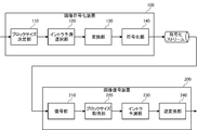
- FIG. 3 is a diagram illustrating the image encoding device 100 and the image decoding device 200 according to Embodiment 1 of the present invention.
- Image coding apparatus 100 according to Embodiment 1 includes a block size determination unit 110, an intra prediction selection unit 120, a conversion unit 130, and an encoding unit 140.
- the image encoding device 100 receives an input image and outputs an encoded stream.
- the image decoding device 200 includes a decoding unit 210, a block size obtaining unit 220, an intra prediction unit 230, and an inverse transform unit 240.
- the encoded stream is input to the image decoding device 200, and a decoded image is output.
- the intra prediction unit 230 uses the same intra prediction mode as HEVC.
- the image encoding device 100 and the image decoding device 200 are realized by hardware such as an information processing device including a CPU (Central Processing Unit), a frame memory, and a hard disk.
- a CPU Central Processing Unit
- a frame memory for storing data
- a hard disk for storing data.
- An input image is input to the image encoding device 100.
- the block size determination unit 110 determines a block size to be subjected to intra prediction encoding based on an input image, and supplies the determined block size and input pixels (input values) corresponding to the block size to the intra prediction selection unit 120.
- the method of determining the block size is not described in detail here, but as is used in HEVC reference software and the like, an RDO (rate) that compares evaluation values of a plurality of block sizes and selects an optimal block size is used. Pre-determination based on the evaluation value may be sufficient.
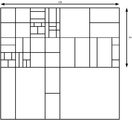
- FIG. 4 illustrates an example in which a part of an image input to the image encoding device 100 is divided into blocks based on the block size determined by the block size determination unit 110.
- the input image is divided using the above block size so that each block does not overlap.
- the intra prediction selection unit 120 selects one intra prediction mode from a plurality of intra prediction modes based on the block size, the input pixels, and the encoded image, and performs encoding based on the selected intra prediction mode.
- the prediction value is derived from the pixel, and the block size, the selected intra prediction mode, the input value, and the prediction value are supplied to the conversion unit 130. Note that encoded pixels are shared by each unit in the image encoding device 100, and are not illustrated here. Details of the intra prediction selection unit 120 will be described later.
- the conversion unit 130 calculates a difference value by subtracting the prediction value from the input value, calculates orthogonal difference and processing such as quantization on the calculated difference value to calculate prediction error data, and calculates a block size, an intra prediction mode, Then, the calculated prediction error data is supplied to the encoding unit 140.
- the encoding unit 140 encodes a header and other information as necessary, encodes a code sequence related to the block size supplied from the conversion unit 130, encodes the intra prediction mode as a code sequence, and encodes prediction error data. And output as an encoded stream. Details of the encoding process in the intra prediction mode will be described later.
- the image coding apparatus 100 repeats the above processing until all the areas of the input image are coded.
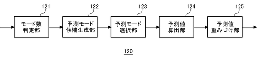
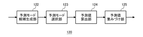
- FIG. 5 is a diagram illustrating a configuration of the intra prediction selection unit 120 according to the first embodiment.
- the intra prediction selection unit 120 includes a mode number determination unit 121, a prediction mode candidate generation unit 122, a prediction mode selection unit 123, a prediction value calculation unit 124, and a prediction value weighting unit 125.
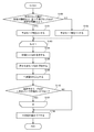
- FIG. 6 is a flowchart illustrating an operation of intra prediction selecting section 120 according to the first embodiment.
- the mode number determination unit 121 checks whether the predicted block width is equal to or larger than a predetermined threshold width and the predicted block height is equal to or larger than a predetermined threshold height (S100).
- the predetermined threshold width and the predetermined threshold height are 32, respectively.
- the predetermined threshold width and the predetermined threshold height are different values, such as 64 and 32. It may be.
- the predetermined threshold width and the predetermined threshold height may be encoded and stored in the header, respectively, as an extended Golomb code string in SPS (Sequence_parameter_set), or the like.
- the number of prediction modes is set to 2 (S101). If the predicted block width is not smaller than the predetermined threshold width and the predicted block height is not larger than the predetermined threshold height (NO in S100), the number of prediction modes is set to 1 (S102).
- the intra prediction selecting unit 120 sets M to 0 when the number of prediction modes is 1, sets M to 0 and 1 when the number of prediction modes is 2, and repeats S103 to S107.
- the number of prediction modes is 1 in consideration of the reduction in the number of steps, only M is processed as 0.
- S103 to S107 may be repeated as 0 and 1.
- the prediction mode candidate generation unit 122 generates a prediction mode candidate list M from encoded neighboring blocks existing around the prediction target block (S104), and supplies the generated prediction mode candidate list M to the prediction mode selection unit 123. I do. The details of the prediction mode candidate list generation process will be described later.
- the prediction mode selection unit 123 calculates an evaluation value of each of the prediction modes 0 to 34 and calculates one selected prediction mode M from the prediction modes 0 to 34 based on the calculated evaluation values of each prediction mode. Is selected (S105), and the selected selected prediction mode M is supplied to the predicted value calculation unit 124. Here, it is assumed that one selected prediction mode M is selected from the prediction modes 0 to 34 by the RDO determination.
- the prediction value calculation unit 124 calculates the prediction value M of the prediction target block based on the selected prediction mode M input from the prediction mode selection unit 123 (S106), and sends the calculated prediction value M to the prediction value weighting unit 125. Supply.
- the predicted value is derived from adjacent pixels.
- FIG. 7 is a diagram for explaining the derivation of the predicted value.
- the prediction target block in FIG. 7 is 32 ⁇ 32, each pixel in the prediction target block exists from P (0,0) to P (31,31), and adjacent pixels are RH-1 to RH63, and RV0 to RV63. Use up to. If there is no adjacent pixel, the pixel is supplemented with a substitute pixel defined by HEVC.
- FIG. 7 shows an example in which the number of prediction modes is 2, the selected prediction mode 0 is the prediction mode 10, and the selected prediction mode 1 is the prediction mode 34 (see FIG. 1).
- P (0,0), P (1,0),..., P (31,0) use RV0 as a predicted value, and P (0,1),. Are the predicted values, and P (0, 31),..., P (31, 31) have the RV31 as the predicted value.
- P (0,0) has RH1 as a predicted value
- P (1,0) and P (0,1) have RH2 as a predicted value
- P (31,31) has RH63 as a predicted value.
- the reference pixels are not generated by filtering the neighboring pixels of the prediction target block, and the neighboring pixels are used as they are in the present embodiment. Therefore, the filtering process is unnecessary in the present embodiment. It is assumed that the calculation of the predicted value is the same as that of the HEVC except that the predicted value is calculated from the reference pixel.
- the selected prediction mode M is not the non-angle intra prediction mode (S110). If the selected prediction mode M is not the non-angle intra prediction mode (YES in S110), the process proceeds to S107. If the selected prediction mode M is the non-angle intra prediction mode (NO in S110), the process proceeds to S108.
- the non-angle intra prediction modes are assumed to be INTRA_PLANAR and INTRA_DC. As described above, in addition to using adjacent pixels at a specific angle such as INTRA_PLANAR and INTRA_DC, in the intra prediction mode using adjacent pixels in a plurality of directions, prediction is performed without allowing the number of prediction modes to be two. By setting the number of modes to 1, an increase in the processing amount can be suppressed. That is, the prediction mode belonging to the non-angle intra prediction mode and the prediction mode belonging to the angle intra prediction mode are not combined.
- the prediction value weighting unit 125 predicts the prediction value supplied from the prediction value calculation unit 124 as it is if the number of prediction modes is 1 or the selected prediction mode 0 is the non-angle intra prediction mode. Output as a value. If the number of prediction modes is 2, the prediction value weighting unit 125 averages the first prediction value of the selected prediction mode 0 and the second prediction value of the selected prediction mode 1 supplied from the prediction value calculation unit 124. And outputs it as a third predicted value (S108).
- the decoding unit 210 decodes a header and other information as needed from the encoded stream, decodes a code sequence related to a block size, a code sequence in an intra prediction mode, and prediction error data from the encoded stream, and decodes the decoded block.
- the code string related to the size, the code string in the intra prediction mode, and the prediction error data are supplied to the block size acquisition unit 220.
- the decoding of the code string in the intra prediction mode is performed based on the syntax relating to the intra prediction mode described later.
- the block size obtaining unit 220 obtains a block size from the code sequence related to the block size supplied from the decoding unit 210, and supplies the block size, the code sequence in the intra prediction mode, and the prediction error data to the intra prediction unit 230.
- the intra prediction unit 230 selects an intra prediction mode from a code string of the intra prediction mode, derives a prediction value from a decoded pixel based on the selected intra prediction mode, and calculates a prediction value, a block size, and prediction error data. Is supplied to the inverse transform unit 240. Note that the decoded pixels are shared by each unit in the image decoding device 200, and are not illustrated here.
- the calculation of the prediction value in the intra prediction unit 230 is the same as the calculation of the prediction value in the intra prediction selection unit 120, and the reproduced image obtained by the image encoding device 100 and the reproduced image output by the image decoding device 200 Are the same. That is, since the intra prediction section 230 and the intra prediction selection section 120 can have the same configuration, the present embodiment will be described assuming that the intra prediction section 230 and the intra prediction selection section 120 have the same configuration.
- FIG. 6 is a flowchart illustrating the operation of the intra prediction selection unit 120.
- the difference from the intra prediction selection unit 120 is S105, and the intra prediction unit 230 performs the following S105D instead of S105.
- the prediction mode selection unit 123 selects one selected prediction mode M based on the code string of the intra prediction mode (S105D), and supplies the selected selected prediction mode M to the predicted value calculation unit 124.
- the code string in the intra prediction mode will be described later.
- the inverse transform unit 240 calculates a difference value by performing processing such as inverse orthogonal transform and inverse quantization on the prediction error data supplied from the intra prediction unit 230, and calculates a reproduced pixel by adding the difference value and the predicted value. Then, a reproduced pixel is output.
- the image decoding apparatus 200 repeats the above processing until all the code strings of the input coded stream are decoded.
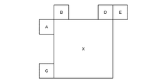
- FIG. 8 is a diagram illustrating a block adjacent to the prediction target block.
- a block X is a prediction target block
- blocks A to E are adjacent blocks.
- the adjacent blocks are from block A to block E.
- blocks A to D may be used, and a block at the upper left (above block A) or a block at the lower left (below block C) of the prediction target block is added. May be.
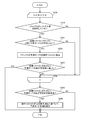
- FIG. 9 is a flowchart for explaining the operation of the generation process of the prediction mode candidate list 0.
- the generation process of the prediction mode candidate list 0 will be described based on FIG. At first, it is assumed that the prediction mode candidate list 0 is empty and the number of candidates included in the prediction mode candidate list 0 is zero.
- the prediction mode candidate list 0 is abbreviated as the candidate list 0.
- the selection prediction mode 0 of the block X is added to the candidate list 0 (S202). Subsequently, it is checked whether the number of prediction modes added to the candidate list 0 has reached a predetermined number (S203). If the number of prediction modes added to the candidate list 0 has reached the predetermined number (S203). YES), the process ends. If the number of prediction modes added to the candidate list 0 has not reached the predetermined number (NO in S203), the process proceeds to S204. Here, the predetermined number is three. If the same prediction mode 0 as the block X exists in the candidate list 0 (NO in S201), the process proceeds to S204.
- the same prediction mode is prevented from overlapping the candidate list 0 based on the priority of the predetermined prediction mode.
- the prediction mode candidates are added to the candidate list 0 in ascending order of priority (S206), and the process ends.
- FIG. 10 shows a table indicating the priorities of the predetermined prediction modes. If the number of prediction modes added to the candidate list 0 is not less than the predetermined number (NO in S205), the process ends.
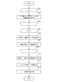
- FIG. 11 is a flowchart for explaining the operation of the generation process of the prediction mode candidate list 1.
- the generation process of the prediction mode candidate list 1 will be described with reference to FIG. At first, it is assumed that the prediction mode candidate list 1 is empty and the number of candidates included in the prediction mode candidate list 1 is zero.
- the prediction mode candidate list is abbreviated as a candidate list.
- the prediction mode of the block X is added to the candidate list 1 (S303). Subsequently, it is checked whether or not the number of prediction modes added to the candidate list 1 has reached a predetermined number (S304). If the number of prediction modes added to the candidate list 1 has reached the predetermined number (S304). YES), the process ends. If the number of prediction modes added to the candidate list 1 has not reached the predetermined number (NO in S304), the process proceeds to S305. Here, the predetermined number is three. If the same selection prediction mode N as the block X exists in the candidate list 1 (NO in S302), the process proceeds to S305.
- FIG. 12 shows a table indicating the priorities of the predetermined prediction modes.
- the table in FIG. 12 differs from the table in FIG. 10 in that the non-angle intra prediction mode (prediction mode 0 and prediction mode 1) is not included. In the priority order, the intra prediction mode in the vertical direction and the intra prediction mode in the horizontal direction are alternately set. If the number of prediction modes added to the candidate list is not less than the predetermined number (NO in S307), the process ends.
- the effect obtained by the first embodiment will be described.
- the size of the prediction target block is large, there is a high possibility that a plurality of edges are included in the prediction target block.
- the prediction efficiency is likely to be reduced.
- FIG. 13 is a diagram illustrating the syntax related to the intra prediction mode according to the first embodiment.
- FIG. 13 shows the syntax of the prediction block, where pbWidth indicates the width of the prediction block and pbHeight indicates the height of the prediction block.
- pbWTThread indicates a predetermined threshold width
- pbHThread indicates a predetermined threshold height. Encoding in the intra prediction mode and decoding in the intra prediction mode are performed based on the syntax in FIG.
- Prev_intra_luma_pred_flag, mpm_idx, and rem_intra_luma_pred_mode are syntaxes regarding the selection prediction mode 0.
- prev_intra_luma_pred_flag is a flag indicating whether or not to select the selected prediction mode 0 from the prediction mode candidate list 0. If the prev_intra_luma_pred_flag is 1, the selected prediction mode 0 is selected from the prediction mode candidate list 0, and if the prev_intra_luma_pred_flag is 0, the selected prediction mode 0 is selected from the intra prediction modes not included in the prediction mode candidate list 0.
- mpm_idx is an index indicating the selected prediction mode 0 selected from the candidates included in the prediction mode candidate list 0.
- rem_intra_luma_pred_mode is an index indicating the selected prediction mode 0 selected from the candidates not included in the prediction mode candidate list 0.
- $ 2nd_prev_intra_luma_pred_flag, 2nd_mpm_idx, and 2nd_rem_intra_luma_pred_mode are syntaxes for the selection prediction mode 1.
- 2nd_prev_intra_luma_pred_flag is a flag indicating whether or not to select the selected prediction mode 1 from the prediction mode candidate list 1. If 2nd_prev_intra_luma_pred_flag is 1, the selected prediction mode 1 is selected from the prediction mode candidate list 1, and if 2nd_prev_intra_luma_pred_flag is 0, the selected prediction mode 1 is selected from the intra prediction modes not included in the prediction mode candidate list 1.
- 2nd_mpm_idx is an index indicating the selected prediction mode 1 selected from the candidates included in the prediction mode candidate list 1.
- 2nd_rem_intra_luma_pred_mode is an index indicating the selected prediction mode 1 selected from the candidates not included in the prediction mode candidate list 1.
- prev_intra_luma_pred_flag, rem_intra_luma_pred_mode, 2nd_prev_intra_luma_pred_flag, and 2nd_rem_intra_luma_pred_mode is binarized fixed length (FL)
- mpm_idx, 2nd_mpm_idx is binarized Toranke over tee Drais (TR).
- Modification 1 of Embodiment 1 In calculating a prediction value in the angle intra prediction mode (prediction mode 2 to prediction mode 34), instead of calculating a prediction value from a pixel adjacent to the prediction target block according to each angle, filtering is performed on a pixel adjacent to the prediction target block.
- the predicted value may be calculated from the reference pixel generated as described above.
- a prediction value is calculated from reference pixels generated by filtering pixels adjacent to the prediction target block, and when the number of prediction modes is 2, a prediction value is calculated from adjacent pixels of the prediction target block. It can also be done. By doing so, the processing amount when the number of prediction modes is 1 and the processing amount when the number of prediction modes is 2 can be made uniform.
- the prediction mode candidate list 1 is generated as shown in FIG. 11 different from the prediction mode candidate list 0, and the selected prediction mode 1 is selected from the prediction mode candidate list 1. Mode 1 may be selected. By doing so, the processing for generating the prediction mode candidate list 1 can be reduced.
- the predetermined number of candidates in the prediction mode candidate list 0 can be made larger than three.
- the predetermined number of candidates in the prediction mode candidate list 0 may be set to five.
- the probability that the selected prediction mode 1 is encoded as 2nd_mpm_idx can be increased, and the encoding efficiency can be improved.
- the predetermined number is larger than three, four or more priority levels of the predetermined prediction mode are prepared in accordance with the predetermined number. At this time, the priority order is set alternately between the intra prediction mode in the vertical direction and the intra prediction mode in the horizontal direction.
- one of the selected prediction modes 1 is selected from the prediction modes 0 to 34.
- the selected prediction mode 1 may be selected from the prediction mode candidate list 1.
- 2nd_prev_intra_luma_pred_flag and 2nd_rem_intra_luma_pred_mode in FIG. 13 are unnecessary, and only 2nd_mpm_idx is needed. By doing so, it is possible to improve the coding efficiency of the selective prediction mode 1.
- the prediction mode candidate list 1 is generated as shown in FIG. 11 regardless of the selected prediction mode 0.
- the prediction mode candidate list 1 is generated based on the selected prediction mode 0.
- Prediction mode candidate list 1 [0] (selection prediction mode 0-1)% 35 (Equation 1)
- Prediction mode candidate list 1 [1] (selection prediction mode 0 + 1)% 35 (Equation 2) “%” Is a remainder operator, and “35” is the number of intra prediction modes. That is, the remainder obtained by dividing (selection prediction mode 0-1) by 35 is added to prediction mode candidate list 1 [0]. Similarly, the remainder obtained by dividing (selection prediction mode 0 + 1) by 35 is added to prediction mode candidate list 1 [1].
- the selected prediction mode 0 does not take the non-angle intra prediction mode
- the selected prediction mode 0 does not take the prediction mode 0 or the prediction mode 1. Therefore, when the selected prediction mode 0 is the prediction mode 2, the prediction mode candidate list 1 [0] becomes the prediction mode 1, but is invalid because the prediction mode 1 is the non-angle intra prediction mode.
- the prediction mode candidate list 1 [1] becomes the prediction mode 0, but is invalid because the prediction mode 0 is the non-angle intra prediction mode.
- FIG. 14 is a diagram illustrating the syntax related to the intra prediction mode of the fourth modification. If 2nd_intra_luma_pred_0_flag is 1, the prediction mode candidate list 1 [0] is selected as the selected prediction mode 1, and if 2nd_intra_luma_pred_0_flag is 0, the prediction mode candidate list 1 [1] is selected as the selected prediction mode 1. By doing so, it is possible to improve the coding efficiency of the selective prediction mode 1. When the selected prediction mode 0 is the prediction mode 2 or the prediction mode 34, the intra prediction mode is uniquely determined to be 0. Therefore, there is no need to encode or decode 2nd_intra_luma_pred_0_flag. Thereby, coding efficiency and processing efficiency can be further improved.
- the predicted value weighting unit 125 of the first embodiment simply averages the predicted value of the selected prediction mode 0 and the predicted value of the selected prediction mode 1 to obtain a predicted value.
- a predicted value in the selected prediction mode 0 and a predicted value in the selected prediction mode 1 are weighted and averaged according to the distance to obtain a predicted value.
- whether the number of prediction modes is one or two depends on whether the width of the prediction target block is equal to or greater than a predetermined threshold width and the height of the prediction target block is equal to or greater than a predetermined threshold height.
- this can be designated by encoding (decoding) a prediction mode number flag indicating whether the number of prediction modes is 1 or 2. In this case, since the control can be finely performed by the flag, the prediction efficiency is improved.
- Embodiment 2 Hereinafter, Embodiment 2 will be described.
- the configuration and operation of the intra prediction selection unit are different from those of the first embodiment.
- FIG. 15 is a diagram illustrating a configuration of the intra prediction selection unit 120 according to the second embodiment of the present invention.
- the intra prediction selection unit 120 includes a prediction mode candidate generation unit 122, a prediction mode selection unit 123, a prediction value calculation unit 124, and a prediction value weighting unit 125.
- FIG. 16 is a flowchart for explaining the operation of the intra prediction selection unit 120.
- the prediction mode candidate generation unit 122 repeats S501 to S503 for the number of non-angle intra prediction modes K, and calculates an evaluation value of the non-angle intra prediction mode K (S502).
- K the evaluation value of INTRA_PLANAR is calculated
- K the evaluation value of INTRA_DC is calculated.
- the prediction mode candidate generation unit 122 repeats S505 to S508 for the number of prediction mode candidate lists M.
- the prediction mode candidate generation unit 122 generates a prediction mode candidate list M from encoded neighboring blocks existing around the prediction target block (S506), and supplies the generated prediction mode candidate list M to the prediction mode selection unit 123. I do.
- the prediction mode candidate list M is generated to include the horizontal intra prediction mode if M is 0, and is generated to include the vertical intra prediction mode if M is 1.
- the prediction mode candidate list M does not include the non-angle intra prediction mode.
- the prediction mode candidate generation unit 122 calculates respective prediction values and evaluation values of the prediction mode 17 from the prediction mode 2 which is the horizontal intra prediction mode included in the prediction mode candidate list 0. Then, one selected prediction mode 0 is selected from the prediction modes 2 to 17 based on the calculated evaluation value of each prediction mode.
- the prediction mode candidate generation unit 122 calculates respective prediction values and evaluation values of the prediction mode 34 from the prediction mode 18 which is the vertical intra prediction mode included in the prediction mode candidate list 1. Then, one selected prediction mode 1 is selected from the prediction modes 18 to 34 based on the calculated evaluation value of each prediction mode (S507). As described above, if M is 0, it indicates a horizontal intra prediction mode, and if M is 1, it indicates a vertical intra prediction mode. That is, M indicates the direction of the intra prediction mode.
- the prediction mode candidate generation unit 122 calculates an evaluation value with two prediction modes by performing a weighted average of the prediction value of the selected prediction mode 0 and the prediction value of the selected prediction mode 1 (S510).
- the prediction mode selection unit 123 selects one intra prediction prediction mode from the prediction mode 0, the prediction mode 1, and the prediction mode number 2. The mode is selected (S511).
- the predicted value weighting unit 125 outputs a predicted value based on the selected intra prediction mode (S512).
- Embodiment 2 differs from Embodiment 1 in the syntax regarding the intra prediction mode.
- FIG. 17 is a diagram illustrating the syntax related to the intra prediction mode according to the second embodiment. Encoding in the intra prediction mode and decoding in the intra prediction mode are performed based on the syntax in FIG.
- Intra_luma_merge_flag is a merge flag indicating whether or not to use the number of prediction modes of an adjacent block and the intra prediction mode as the number of prediction modes of the prediction target block and the intra prediction mode.
- Intra_luma_merge_idx indicates the number of prediction modes of the prediction target block, the number of prediction modes used as the intra prediction mode, and an adjacent block having the intra prediction mode.
- FIG. 18 is a table showing the relationship between intra_luma_merge_idx and adjacent blocks.
- intra_luma_merge_idx when intra_luma_merge_idx is 0, the number of prediction modes of the adjacent block A is 1, and the selected prediction mode 0 is the prediction mode 3, the number of prediction modes of the prediction target block is 1, and the selected prediction mode 0 is the same as the prediction mode 3.
- intra_luma_merge_idx is 2
- the selected prediction mode 0 is the prediction mode 3
- the selected prediction mode 1 is the prediction mode 20
- the number is 2
- the selected prediction mode 0 is the prediction mode 3
- the selected prediction mode 1 is the prediction mode 20.
- Intra_luma_non_angular_pred_flag is a flag indicating whether or not the mode is the non-angle intra prediction mode. If the flag indicating whether the mode is the non-angle intra prediction mode indicates that the mode is the non-angle intra prediction mode (intra_luma_non_angular_pred_flag is 1), the non_angular_idx is encoded (decoded), and the intra prediction mode indicated by the non_angular_idx is selected. Is selected as non_angular_idx indicates a prediction mode of the non-angle intra prediction mode. If non_angular_idx is 0, it indicates INTRA_PLANAR, and if it is 1, it indicates INTRA_DC.
- intra_luma_non_angular_pred_flag 0
- prev_intra_luma_pred_h_flag mpm_idx_h
- mpm_idx_h rem_in_de_de_decoding of the mpm_idx_h
- rem_intra_lum_de_luma of the prev_intra_luma_pred_h_flag mpm_idx_h
- mpm_idx_h rem_intra_lum, and the like
- Intra_luma_pred_idc indicates the number of prediction modes and the direction of intra prediction. If intra_luma_pred_idc is 0, the number of prediction modes is 1, indicating a horizontal intra prediction mode; if intra_luma_pred_idc is 1, the number of prediction modes is 1, indicating a vertical intra prediction mode, and intra_luma_pred_idc is 2, Indicates that the number of prediction modes is two.
- Prev_intra_luma_pred_h_flag, mpm_idx_h, and rem_intra_luma_pred_mode_h are syntaxes for the horizontal intra prediction mode.
- prev_intra_luma_pred_v_flag, mpm_idx_v, and rem_intra_luma_pred_mode_v are syntaxes for a vertical intra prediction mode.
- rem_intra_luma_pred_mode_h and rem_intra_luma_pred_mode_v do not include the non-angle intra prediction mode.
- the code of the prediction mode that is two or the prediction mode that does not exist in the prediction mode candidate list is used. Conversion efficiency can be improved.
- the intra prediction modes are predicted from prediction modes 0 and 1, which are non-angle intra prediction modes, prediction modes 17 from prediction modes 2, which are horizontal intra prediction modes, and prediction modes 18, which are prediction modes, which are vertical intra prediction modes.
- the syntax regarding the intra prediction mode is divided into a syntax element for a non-angle intra prediction mode, a syntax element for a horizontal prediction, and a syntax element for a vertical prediction, It is possible to improve coding efficiency when selecting a prediction mode that does not exist in the prediction mode candidate list.
- the intra_luma_non_angular_pred_flag in front of rem_intra_luma_pred_mode_h and Rem_intra_luma_pred_mode_v, in addition to the intra prediction mode candidates included in the prediction mode candidate list in rem_intra_luma_pred_mode_h and Rem_intra_luma_pred_mode_v, it is not necessary to include a non-angular intra prediction mode. Therefore, the angle intra prediction mode that can be specified by rem_intra_luma_pred_mode_h or rem_intra_luma_pred_mode_v can be increased, so that encoding efficiency can be improved.
- a new angle may be provided between the prediction mode 9 and the prediction mode 10 or between the prediction mode 10 and the prediction mode 11, In the case of a direction intra prediction mode, a new angle intra prediction mode may be provided between the prediction mode 25 and the prediction mode 26 or between the prediction mode 26 and the prediction mode 27.
- the non-angle intra prediction mode has a higher selection probability than the angle intra prediction mode. Therefore, by encoding (decoding) intra_luma_non_angular_pred_flag, which is an independent syntax indicating the non-angle intra prediction mode, before mpm_idx_h or mpm_idx_v, the non-angle intra prediction mode is added to the prediction mode candidate list 0 or the prediction mode candidate list 1. There is no need to include it. Therefore, when the selected prediction mode is the non-angle intra prediction mode, the processing cost for generating the prediction mode candidate list 0 and the prediction mode candidate list 1 can be reduced.
- intra_luma_non_angular_pred_flag which is an independent syntax indicating the non-angle intra prediction mode
- intra_luma_merge_idx, intra_luma_merge_idx, intra_luma_non_angular_pred_flag, and non_angular_idx can be applied to the previous example of FIG.
- the prediction mode candidate list 0 is a horizontal intra prediction mode
- the prediction mode candidate list 1 is a vertical intra prediction mode
- the prediction mode candidate list and the syntax of the intra prediction mode are matched.
- the prediction mode candidate list may include all of the non-angle intra prediction mode, the horizontal intra prediction mode, and the vertical intra prediction mode, as in the prediction mode candidate list of the first embodiment.
- FIG. 19 is a diagram illustrating the syntax related to the intra prediction mode according to the second modification of the second embodiment. The coding of the intra prediction mode and the decoding of the intra prediction mode relating to the intra prediction mode are performed based on the syntax in FIG.
- the selected prediction mode is selected from the non-angle intra prediction mode or the prediction mode candidate list.
- the flag indicating whether or not the mode is the non-angle intra prediction mode indicates that the mode is the non-angle intra prediction mode
- the non-angle intra prediction mode indicated by non_angular_idx is selected as the selected prediction mode.
- the flag indicating whether the mode is the non-angle intra prediction mode indicates that the mode is not the non-angle intra prediction mode
- the mpm index (mpm_idx) is encoded (decoded) and indicated by mpm_idx included in the prediction mode candidate list.
- the intra prediction mode candidate to be selected is selected as the selected prediction mode.
- the intra prediction mode indicated by rem_intra_luma_pred_mode is selected as the selected prediction mode from the non-angle intra prediction mode and the intra prediction mode not included in the prediction mode candidate list.
- FIG. 20 is a diagram illustrating another syntax related to the intra prediction mode according to the second modification of the second embodiment. The coding of the intra prediction mode and the decoding of the intra prediction mode regarding the intra prediction mode are performed based on the syntax in FIG.
- intra_luma_non_angular_pred_flag 1
- the intra prediction mode candidate indicated by mpm_idx included in the prediction mode candidate list is selected as the selected prediction mode.
- intra_luma_non_angular_pred_flag 0 and prev_intra_luma_pred_flag is 0, the intra mode selected as the rem_intra_luma_pred_mode selected as the rem_intra_luma_pred_mode from the intra prediction mode that is not the non-angle intra prediction mode and is not included in the prediction mode candidate list.
- rem_intra_luma_pred_mode only needs to indicate 30 intra prediction modes except all 35 intra prediction modes except the intra prediction mode candidates and the non-angle intra prediction mode. Can be added to improve coding efficiency.
- a new intra prediction mode for example, between prediction mode 9 and prediction mode 10, between prediction mode 10 and prediction mode 11, between prediction mode 25 and prediction mode 26, and between prediction mode 26 and prediction mode 27 A new angle intra prediction mode may be provided between them. Also, in FIG.
- the non-angle intra prediction mode can be encoded (decoded) with intra_luma_non_angular_pred_flag and non_angular_idx, the processing efficiency and the code are increased when the selection probability of the non-angle intra prediction mode is relatively higher than other intra prediction modes. The conversion efficiency is improved.
- the prediction mode candidate list includes INTRA_DC of the non-angle intra prediction mode, intra prediction mode of the horizontal direction, and intra prediction mode of the vertical prediction mode.
- INTRA_PLANAR is not included in the prediction mode candidate list.
- the flag (intra_luma_non_angular_pred_flag) indicating whether or not the mode is the non-angle intra prediction mode is encoded (decoded).
- a flag indicating whether or not the non-angle intra prediction mode is set to a flag indicating whether or not the intra prediction mode INTRA_PLANAR having the highest selection probability among the intra prediction modes.
- indexes such as prev_intra_luma_pred_flag and mpm_idx are encoded (decoded), and an intra prediction mode other than INTRA_PLANAR is selected as the selected prediction mode.
- rem_intra_luma_pred_mode only needs to indicate 31 intra prediction modes except 35 intra prediction modes and the intra prediction mode candidates other than INTRA_PLANAR, and a new intra prediction mode is added. Can improve the coding efficiency.
- a new intra prediction mode for example, between prediction mode 9 and prediction mode 10, between prediction mode 10 and prediction mode 11, between prediction mode 25 and prediction mode 26, and between prediction mode 26 and prediction mode 27 A new angle intra prediction mode may be provided between them. Also, in FIG.
- INTRA_PLANAR since INTRA_PLANAR can be encoded with only one flag of intra_luma_non_angular_pred_flag, the coding efficiency and processing efficiency can be optimized when the selection probability of INTRA_PLANAR is relatively higher than other intra prediction modes. 19, INTRA_PLANAR can be encoded with two flags, prev_intra_luma_pred_flag and intra_luma_non_angular_pred_flag, so that the encoding efficiency and processing efficiency are improved when the selection probability of INTRA_PLANAR is relatively higher than other intra prediction modes.
- the coded stream output by the image coding apparatus according to the embodiment described above has a specific data format so that it can be decoded according to the coding method used in the embodiment, An image decoding device corresponding to the encoding device can decode the encoded stream of this specific data format.
- the encoded stream is converted into a data format suitable for the transmission form of the communication path and transmitted.
- the image transmitting apparatus converts the encoded stream output from the image encoding apparatus into encoded data of a data format suitable for the transmission form of the communication channel and transmits the encoded data to the network, and receives the encoded data from the network.
- an image receiving device that restores the encoded stream and supplies the decoded image to the image decoding device.
- the image transmitting apparatus includes a memory for buffering an encoded stream output from the image encoding apparatus, a packet processing unit that packetizes the encoded stream and converts the encoded stream into encoded data, and converts the packetized encoded data via a network. And a transmitting unit for transmitting.
- the image receiving device receives a packetized encoded data via a network, a packet processing unit that performs packet processing on the received encoded data to form an encoded stream, and buffers the encoded stream. And a coded stream in the buffer is supplied to the image decoding device.
- a display device can be provided by adding a display unit that displays an image decoded by the image decoding device to the configuration. In that case, the display unit displays the decoded image signal decoded by the image decoding device on a screen.
- an imaging unit may be added to the configuration, and a captured image may be input to an image encoding device to form an imaging device.
- the imaging unit inputs the captured image signal to the block size determination unit 110.
- the above encoding and decoding processes can be realized as a transmission, storage, and reception device using hardware, and are stored in a ROM (read only memory), a flash memory, or the like. It can also be realized by firmware or software such as a computer. To provide the firmware program and the software program by recording them on a computer-readable recording medium, to provide the firmware program and the software program from a server through a wired or wireless network, and to provide the data broadcast of a terrestrial or satellite digital broadcast. Is also possible.
- the embodiments may be specified by the following items.
- a prediction mode candidate generation unit (122) that generates a first intra prediction mode candidate list and a second intra prediction mode candidate list from intra prediction modes of blocks adjacent to the prediction target block;
- a prediction mode selection unit (123) that selects a first intra prediction mode and a second intra prediction mode from the first intra prediction mode candidate list and the second intra prediction mode candidate list, respectively;
- a first prediction value is calculated from encoded pixels adjacent to the prediction target block based on the first intra prediction mode, and a code adjacent to the prediction target block is calculated based on the second intra prediction mode.
- a prediction value calculation unit (124) that calculates a second prediction value from the pixel that has been converted
- a predicted value weighting unit (125) for calculating a third predicted value based on the first predicted value and the second predicted value;
- An image encoding device (100) comprising: [Item 2] The said prediction value weighting part (125) calculates the said 3rd prediction value by carrying out simple average or a weighted average of the said 1st prediction value and a 2nd prediction value, The item 3 characterized by the above-mentioned. Image coding device (100). [Item 3]
- the prediction mode candidate generation unit (122) generates the second intra prediction mode candidate list when the number of intra prediction modes is two, and the second intra prediction mode when the number of intra prediction modes is one.
- the prediction mode selection unit (123) selects the second intra prediction mode if the number of intra prediction modes is two, and selects the second intra prediction mode if the number of intra prediction modes is one Without
- the prediction value calculation unit (124) calculates a second prediction value if the number of intra prediction modes is two, and does not calculate a second prediction value if the number of intra prediction modes is one, If the number of intra prediction modes is 2, the prediction value weighting unit (125) calculates a third prediction value based on the first prediction value and the second prediction value, and The image encoding device (100) according to item 1 or 2, wherein if the number is 1, the first predicted value is used as a predicted value as it is.
- the width of the prediction target block is equal to or greater than a predetermined threshold width and the height of the prediction target block is equal to or greater than a predetermined threshold height, the number of intra prediction modes is set to 2, and the width of the prediction target block is set to a predetermined threshold.
- Item 3 is characterized by further comprising a mode number determination unit (121) for setting the number of intra prediction modes to 1 when the width is equal to or greater than the width and the height of the prediction target block is not equal to or greater than a predetermined threshold height.
- Image coding device (100).
- the mode number determination unit (121) sets the number of intra prediction modes to 1 when the first intra prediction mode is the non-angle intra prediction mode. 100).
- An image encoding method comprising: [Item 10] A prediction mode candidate step of generating a first intra prediction mode candidate list and a second intra prediction mode candidate list from intra prediction modes of blocks adjacent to the prediction target block; A prediction mode selection step of selecting a first intra prediction mode and a second intra prediction mode from the first intra prediction mode candidate list and the second intra prediction mode candidate list, respectively; A first prediction value is calculated from encoded pixels adjacent to the prediction target block based on the first intra prediction mode, and a code adjacent to the prediction target block is calculated based on the second intra prediction mode.
- An image encoding program characterized by causing a computer to execute the following.
- An image encoding device comprising: an encoding unit (140) that performs encoding.
- An image encoding method in which a plurality of intra prediction modes for performing intra prediction using encoded pixels adjacent to a prediction target block are defined, The plurality of intra prediction modes are classified into a non-angle intra prediction mode and an angle intra prediction mode, and a code string is generated by dividing the syntax elements into the syntax elements of the non-angle intra prediction mode and the syntax elements of the angle intra prediction mode.
- An image encoding method comprising: [Item 13] An image encoding program in which a plurality of intra prediction modes for performing intra prediction using encoded pixels adjacent to the prediction target block are defined, The plurality of intra prediction modes are classified into a non-angle intra prediction mode and an angle intra prediction mode, and a code string is generated by dividing into a syntax element of the non-angle intra prediction mode and a syntax element of the angle intra prediction mode.
- An image encoding program characterized by causing a computer to execute an encoding step.
- An image encoding device (100) in which a plurality of intra prediction modes for performing intra prediction using encoded pixels adjacent to a prediction target block are defined, The first intra prediction mode and the second intra prediction mode of a block adjacent to the prediction target block are obtained as the first intra prediction mode and the second intra prediction mode of the prediction target block, and the An image encoding device (100), comprising an encoding unit (140) for encoding.
- An image encoding method in which a plurality of intra prediction modes for performing intra prediction using encoded pixels adjacent to a prediction target block are defined, The first intra prediction mode and the second intra prediction mode of a block adjacent to the prediction target block are obtained as the first intra prediction mode and the second intra prediction mode of the prediction target block, and the An image encoding method comprising an encoding step of encoding.
- An image encoding program in which a plurality of intra prediction modes for performing intra prediction using encoded pixels adjacent to the prediction target block are defined, The first intra prediction mode and the second intra prediction mode of a block adjacent to the prediction target block are obtained as the first intra prediction mode and the second intra prediction mode of the prediction target block, and the An image encoding program for causing a computer to execute an encoding step of encoding.
- a prediction mode candidate generation unit (122) that generates a first intra prediction mode candidate list and a second intra prediction mode candidate list from intra prediction modes of blocks adjacent to the prediction target block;
- a prediction mode selection unit (123) that selects a first intra prediction mode from the code string of the first intra prediction mode and selects a second intra prediction mode from the code string of the second intra prediction mode;
- a first prediction value is calculated from decoded pixels adjacent to the prediction target block based on the first intra prediction mode, and a decoded prediction value adjacent to the prediction target block is calculated based on the second intra prediction mode.
- the prediction mode candidate generation unit (122) generates the second intra prediction mode candidate list when the number of intra prediction modes is two, and the second intra prediction mode when the number of intra prediction modes is one.
- the prediction mode selection unit (123) selects the second intra prediction mode if the number of intra prediction modes is two, and selects the second intra prediction mode if the number of intra prediction modes is one Without
- the prediction value calculation unit (124) calculates a second prediction value if the number of intra prediction modes is two, and does not calculate a second prediction value if the number of intra prediction modes is one, If the number of intra prediction modes is 2, the prediction value weighting unit (125) calculates a third prediction value based on the first prediction value and the second prediction value, and
- the image decoding device (200) according to item 17 or 18, wherein if the number is 1, the first predicted value is used as a predicted value as it is.
- Item 20 If the width of the prediction target block is equal to or greater than a predetermined threshold width and the height of the prediction target block is equal to or greater than a predetermined threshold height, the number of intra prediction modes is set to 2, and the width of the prediction target block is set to a predetermined threshold.
- Item 19 is characterized by further comprising a mode number determination unit (121) for setting the number of intra prediction modes to 1 if the width is equal to or more than the width and the height of the prediction target block is not equal to or greater than a predetermined threshold height.
- [Item 21] The image decoding apparatus (200) according to item 20, wherein the mode number determination unit (121) sets the number of intra prediction modes to 1 when the first intra prediction mode is a non-angle intra prediction mode. ).
- [Item 22] The image decoding according to any one of items 17 to 21, further comprising a decoding unit (210) for decoding the code string in the second intra prediction mode when the number of intra prediction modes is two. Apparatus (200).
- [Item 23] A plurality of intra prediction modes for performing intra prediction using decoded pixels adjacent to the prediction target block are classified into a non-angle intra prediction mode and an angle intra prediction mode, and syntax elements of the non-angle intra prediction mode 22.
- the image decoding apparatus according to any one of items 17 to 21, further comprising: a decoding unit (210) configured to decode a code string generated by dividing the code string into syntax elements in the angle intra prediction mode. (200).
- a decoding unit (210) configured to decode a code string generated by dividing the code string into syntax elements in the angle intra prediction mode. (200).
- [Item 24] Acquiring the first intra prediction mode and the second intra prediction mode of a block adjacent to the prediction target block as the first intra prediction mode and the second intra prediction mode of the prediction target block,
- the image decoding device (200) according to any one of items 17 to 21, further comprising a decoding unit (210) configured to decode a code string encoded into one syntax element.
- a first prediction value is calculated from decoded pixels adjacent to the prediction target block based on the first intra prediction mode, and a decoded prediction value adjacent to the prediction target block is calculated based on the second intra prediction mode.
- An image decoding method comprising: [Item 26] A prediction mode candidate generating step of generating a first intra prediction mode candidate list and a second intra prediction mode candidate list from an intra prediction mode of a block adjacent to the prediction target block; A prediction mode selection step of selecting a first intra prediction mode from the code string of the first intra prediction mode, and selecting a second intra prediction mode from the code string of the second intra prediction mode; A first prediction value is calculated from decoded pixels adjacent to the prediction target block based on the first intra prediction mode, and a decoded prediction value adjacent to the prediction target block is calculated based on the second intra prediction mode.
- An image decoding apparatus in which a plurality of intra prediction modes for performing intra prediction using decoded pixels adjacent to a prediction target block are defined, The codes generated by dividing the plurality of intra prediction modes into a non-angle intra prediction mode and an angle intra prediction mode, and dividing the syntax elements into the syntax elements of the non-angle intra prediction mode and the syntax elements of the angle intra prediction mode.
- An image decoding device comprising a decoding unit (210) for decoding a column.
- An image decoding method in which a plurality of intra prediction modes for performing intra prediction using decoded pixels adjacent to a prediction target block are defined, The codes generated by dividing the plurality of intra prediction modes into a non-angle intra prediction mode and an angle intra prediction mode, and dividing the syntax elements into the syntax elements of the non-angle intra prediction mode and the syntax elements of the angle intra prediction mode.
- An image decoding method comprising a decoding step of decoding a column.
- An image decoding program in which a plurality of intra prediction modes for performing intra prediction using decoded pixels adjacent to the prediction target block are defined, The codes generated by dividing the plurality of intra prediction modes into a non-angle intra prediction mode and an angle intra prediction mode, and dividing the syntax elements into the syntax elements of the non-angle intra prediction mode and the syntax elements of the angle intra prediction mode.
- An image decoding program for causing a computer to execute a decoding step of decoding a column.
- An image decoding apparatus (200) in which a plurality of intra prediction modes for performing intra prediction using decoded pixels adjacent to a prediction target block are defined, The first intra prediction mode and the second intra prediction mode of a block adjacent to the prediction target block are obtained as the first intra prediction mode and the second intra prediction mode of the prediction target block, and the An image decoding device (200) comprising a decoding unit (210) for decoding an encoded code sequence.
- An image decoding method in which a plurality of intra prediction modes for performing intra prediction using decoded pixels adjacent to a prediction target block are defined, The first intra prediction mode and the second intra prediction mode of a block adjacent to the prediction target block are obtained as the first intra prediction mode and the second intra prediction mode of the prediction target block, and the An image decoding method, comprising a decoding step of decoding an encoded code sequence.
- An image decoding program in which a plurality of intra prediction modes for performing intra prediction using decoded pixels adjacent to the prediction target block are defined, The first intra prediction mode and the second intra prediction mode of a block adjacent to the prediction target block are obtained as the first intra prediction mode and the second intra prediction mode of the prediction target block, and the An image decoding program for causing a computer to execute a decoding step of decoding an encoded code sequence.
- the present invention provides an image encoding device that performs image encoding and decoding using intra prediction, an image encoding method, and an image encoding program, and an image decoding device that performs image decoding using intra prediction.
- the present invention can be used for an image decoding method and an image decoding program.
Abstract
Description
図1は、HEVCのイントラ予測モードを説明する図である。図1のようにHEVCではイントラ予測モードとして予測モード0から予測モード34までの35モードが定義されている。予測モード0はINTRA_PLANARであり、予測対象ブロックの隣接画素をフィルタリングして生成した4つの参照画素を内挿予測して予測値を算出する。予測モード1はINTRA_DCであり、予測対象ブロックの予測ブロックの幅の2倍の水平方向の隣接画素と、予測ブロックの高さの2倍の垂直方向の隣接画素とを平均して予測値を算出する。予測モード2から予測モード34は、それぞれの角度に応じて予測対象ブロックの隣接画素をフィルタリングして生成した参照画素から予測値を算出する。ここで、予測対象ブロックの隣接画素のフィルタリングについては、予測対象ブロックのサイズが大きい場合に作用しやすく、予測対象ブロックのサイズが小さい場合に作用しにくくしている。なお、フィルタリングには1:2:1の3タップフィルタが利用される。
以下、図面とともに本発明の実施の形態に係る画像符号化装置、画像符号化方法、及び画像符号化プログラム、並びに画像復号装置、画像復号方法、及び画像復号プログラムの詳細について説明する。
図4は、画像符号化装置100に入力される画像の一部の領域が、ブロックサイズ決定部110で決定されたブロックサイズに基づいて、ブロックに分割されている例を示す。ブロックサイズは4×4、8×4、4×8、8×8、16×8、8×16、32×32、・・・、128×64、64×128、128×128が存在し、入力される画像は各ブロックが重複しないように上記のブロックサイズを用いて分割される。
図5は、実施の形態1のイントラ予測選択部120の構成を示す図である。イントラ予測選択部120はモード数判定部121、予測モード候補生成部122、予測モード選択部123、予測値算出部124、及び予測値重みづけ部125を含む。
図8は、予測対象ブロックの隣接ブロックを説明する図である。図8において、ブロックXは予測対象ブロックであり、ブロックAからブロックEが隣接ブロックである。ここでは、隣接ブロックをブロックAからブロックEとしたが、ブロックAからブロックDでもよく、更に予測対象ブロックの左上(ブロックAの上)のブロックや左下(ブロックCの下)のブロックなどを追加してもよい。
図13は、実施の形態1のイントラ予測モードに関するシンタックスを説明する図である。図13は予測ブロックのシンタックスであり、pbWidthは予測ブロックの幅、pbHeightは予測ブロックの高さを示す。pbWThreadは所定の閾幅、pbHThreadは所定の閾高を示す。イントラ予測モードの符号化やイントラ予測モードの復号は図13のシンタックスに基づいて行われる。
以下、実施の形態1の変形例1について説明する。角度イントラ予測モード(予測モード2から予測モード34)の予測値の算出において、それぞれの角度に応じて予測対象ブロックの隣接画素から予測値を算出するのではなく、予測対象ブロックの隣接画素をフィルタリングして生成した参照画素から予測値を算出してもよい。
以下、実施の形態1の変形例2について説明する。実施の形態1では予測モード候補リスト1を予測モード候補リスト0とは異なる図11のように生成し、予測モード候補リスト1から選択予測モード1を選択したが、予測モード候補リスト0から選択予測モード1を選択してもよい。このようにすることで、予測モード候補リスト1を生成する処理を削減することができる。
以下、実施の形態1の変形例3について説明する。実施の形態1では選択予測モード1を予測モード0から予測モード34の中から1つ選択した。変形例3では、選択予測モード1を予測モード候補リスト1から選択してもよい。このとき、図13の2nd_prev_intra_luma_pred_flagと2nd_rem_intra_luma_pred_modeは不要となり、2nd_mpm_idxだけで済む。このようにすることで、選択予測モード1の符号化効率を向上させることができる。
以下、実施の形態1の変形例4について説明する。実施の形態1では予測モード候補リスト1を選択予測モード0とは無関係に図11のように生成した。変形例4では予測モード候補リスト1を選択予測モード0に基づいて生成する。
予測モード候補リスト1[0]=(選択予測モード0-1)%35 ・・・(式1)
予測モード候補リスト1[1]=(選択予測モード0+1)%35 ・・・(式2)
「%」は剰余演算子であり、「35」はイントラ予測モード数である。すなわち、(選択予測モード0-1)を35で割った余りが、予測モード候補リスト1[0]に追加される。同様に、(選択予測モード0+1)を35で割った余りが、予測モード候補リスト1[1]に追加される。余りは0~34の範囲に収まる。
なお、選択予測モード0は非角度イントラ予測モードをとらないため、選択予測モード0が予測モード0または予測モード1をとることはない。そのため、選択予測モード0が予測モード2である場合、予測モード候補リスト1[0]は予測モード1となるが、予測モード1は非角度イントラ予測モードであるため無効とする。同様に、選択予測モード0が予測モード34である場合、予測モード候補リスト1[1]は予測モード0となるが、予測モード0は非角度イントラ予測モードであるため無効とする。
図14は、変形例4のイントラ予測モードに関するシンタックスを説明する図である。2nd_intra_luma_pred_0_flagが1であれば、選択予測モード1として予測モード候補リスト1[0]を選択し、2nd_intra_luma_pred_0_flagが0であれば、選択予測モード1として予測モード候補リスト1[1]を選択する。このようにすることで、選択予測モード1の符号化効率を向上させることができる。選択予測モード0が予測モード2または予測モード34である場合、イントラ予測モードは一意に0に決定される。そのため、2nd_intra_luma_pred_0_flagを符号化または復号する必要がない。これにより、符号化効率と処理効率をさらに向上させることができる。
以下、実施の形態1の変形例5について説明する。実施の形態1の予測値重みづけ部125は、予測モード数が2であれば、選択予測モード0の予測値と選択予測モード1の予測値を単純平均して予測値とした。変形例5では、選択予測モード0の予測値と選択予測モード1の予測値を距離に応じて加重平均して予測値とする。
PP=(N0*d1+N1*d0)/(d0+d1) ・・・(式3)
以下、実施の形態1の変形例6について説明する。実施の形態1では、予測モード数を1または2のいずれにするかは、予測対象ブロックの幅が所定の閾幅以上で且つ前記予測対象ブロックの高さが所定の閾高以上であるか否かで決定した。これを例えば、予測モード数が1であるか2であるかを示す予測モード数フラグを符号化(復号)して指定することもできる。この場合、フラグにより精細に制御できるため、予測効率が向上する。
以下、実施の形態2について説明する。実施の形態1とはイントラ予測選択部の構成と動作が異なる。
以下、実施の形態2の変形例1について説明する。実施の形態2では、予測モード候補リスト0は水平方向のイントラ予測モードとし、予測モード候補リスト1は垂直方向のイントラ予測モードとし、予測モード候補リストとイントラ予測モードに関するシンタックスの分類を一致させたが、これに限定されない。
予測モード候補リストが水平方向のイントラ予測モードと垂直方向のイントラ予測モードのイントラ予測モードを含む場合について説明する。ただし、非角度イントラ予測モードは予測モード候補リストには含まれない。図19は、実施の形態2の変形例2のイントラ予測モードに関するシンタックスを説明する図である。イントラ予測モードに関するイントラ予測モードの符号化やイントラ予測モードの復号は図19のシンタックスに基づいて行われる。
続いて、予測モード候補リストが非角度イントラ予測モードのINTRA_DC、水平方向のイントラ予測モード、及び垂直方向のイントラ予測モードのイントラ予測モードを含む場合について説明する。ただし、INTRA_PLANARは予測モード候補リストには含まれない。実施の形態2では、非角度イントラ予測モードであるか否かを示すフラグ(intra_luma_non_angular_pred_flag)を符号化(復号)した。実施の形態2の変形例3では、非角度イントラ予測モードであるか否かを示すフラグをイントラ予測モードの中で最も選択確率の高いイントラ予測モードであるINTRA_PLANARであるか否かを示すフラグに限定して符号化(復号)する。選択予測モードがINTRA_PLANARである場合、non_angular_idxは符号化(復号)する必要はなく、INTRA_PLANARの符号化効率を改善できる。INTRA_PLANARであるか否かを示すフラグがINTRA_PLANARであることを示す場合は、INTRA_PLANARが選択予測モードとして選択される。図19では、INTRA_PLANARであるか否かを示すフラグがINTRA_PLANARでないことを示す場合は、mpm_idxが符号化(復号)されて、INTRA_PLANAR以外のイントラ予測モードが選択予測モードとして選択される。図20では、INTRA_PLANARであるか否かを示すフラグがINTRA_PLANARでないことを示す場合は、prev_intra_luma_pred_flag、mpm_idx等のインデックスが符号化(復号)されて、INTRA_PLANAR以外のイントラ予測モードが選択予測モードとして選択される。
予測対象ブロックに隣接するブロックのイントラ予測モードから第1のイントラ予測モード候補リストと第2のイントラ予測モード候補リストを生成する予測モード候補生成部(122)と、
前記第1のイントラ予測モード候補リストと前記第2のイントラ予測モード候補リストからそれぞれ第1のイントラ予測モードと第2のイントラ予測モードを選択する予測モード選択部(123)と、
前記第1のイントラ予測モードに基づいて前記予測対象ブロックに隣接する符号化済みの画素から第1の予測値を算出し、前記第2のイントラ予測モードに基づいて前記予測対象ブロックに隣接する符号化済みの画素から第2の予測値を算出する予測値算出部(124)と、
前記第1の予測値と第2の予測値をもとに第3の予測値を算出する予測値重みづけ部(125)と、
を有することを特徴とする画像符号化装置(100)。
[項目2]
前記予測値重みづけ部(125)は、前記第1の予測値と第2の予測値を単純平均または加重平均して前記第3の予測値を算出することを特徴とする項目1に記載の画像符号化装置(100)。
[項目3]
前記予測モード候補生成部(122)は、イントラ予測モードの数が2であれば前記第2のイントラ予測モード候補リストを生成し、イントラ予測モードの数が1であれば前記第2のイントラ予測モード候補リストを生成せず、
前記予測モード選択部(123)は、イントラ予測モードの数が2であれば前記第2のイントラ予測モードを選択し、イントラ予測モードの数が1であれば前記第2のイントラ予測モードを選択せず、
前記予測値算出部(124)は、イントラ予測モードの数が2であれば第2の予測値を算出し、イントラ予測モードの数が1であれば第2の予測値を算出せず、
前記予測値重みづけ部(125)は、イントラ予測モードの数が2であれば前記第1の予測値と第2の予測値をもとに第3の予測値を算出し、イントラ予測モードの数が1であれば、前記第1の予測値をそのまま予測値とすることを特徴とする項目1または2に記載の画像符号化装置(100)。
[項目4]
前記予測対象ブロックの幅が所定の閾幅以上で且つ前記予測対象ブロックの高さが所定の閾高以上であれば、イントラ予測モードの数を2とし、前記予測対象ブロックの幅が所定の閾幅以上で且つ前記予測対象ブロックの高さが所定の閾高以上でなければ、イントラ予測モードの数を1とするモード数判定部(121)をさらに有することを特徴とする項目3に記載の画像符号化装置(100)。
[項目5]
前記モード数判定部(121)は、前記第1のイントラ予測モードが非角度イントラ予測モードのとき、イントラ予測モードの数を1とすることを特徴とする項目4に記載の画像符号化装置(100)。
[項目6]
イントラ予測モードの数が2のとき、前記第2のイントラ予測モードの情報を符号列として符号化する符号化部(140)をさらに有することを特徴とする項目3から5のいずれか1項に記載の画像符号化装置(100)。
[項目7]
前記予測対象ブロックに隣接する符号化済みの画素を用いてイントラ予測を行う複数のイントラ予測モードを、非角度イントラ予測モードと角度イントラ予測モードに分類して、前記非角度イントラ予測モードのシンタックス要素と前記角度イントラ予測モードのシンタックス要素に分割して符号列を生成する符号化部(140)をさらに有することを特徴とする項目1から5のいずれか1項に記載の画像符号化装置(100)。
[項目8]
前記予測対象ブロックに隣接するブロックの前記第1のイントラ予測モードと前記第2のイントラ予測モードを、前記予測対象ブロックの前記第1のイントラ予測モードと前記第2のイントラ予測モードとして取得し、1つのシンタックス要素に符号化する符号化部(140)をさらに有することを特徴とする項目1から4のいずれか1項に記載の画像符号化装置(100)。
[項目9]
予測対象ブロックに隣接するブロックのイントラ予測モードから第1のイントラ予測モード候補リストと第2のイントラ予測モード候補リストを生成する予測モード候補ステップと、
前記第1のイントラ予測モード候補リストと前記第2のイントラ予測モード候補リストからそれぞれ第1のイントラ予測モードと第2のイントラ予測モードを選択する予測モード選択ステップと、
前記第1のイントラ予測モードに基づいて前記予測対象ブロックに隣接する符号化済みの画素から第1の予測値を算出し、前記第2のイントラ予測モードに基づいて前記予測対象ブロックに隣接する符号化済みの画素から第2の予測値を算出する予測値算出ステップと、
前記第1の予測値と第2の予測値をもとに第3の予測値を算出する予測値重みづけステップと、
を有することを特徴とする画像符号化方法。
[項目10]
予測対象ブロックに隣接するブロックのイントラ予測モードから第1のイントラ予測モード候補リストと第2のイントラ予測モード候補リストを生成する予測モード候補ステップと、
前記第1のイントラ予測モード候補リストと前記第2のイントラ予測モード候補リストからそれぞれ第1のイントラ予測モードと第2のイントラ予測モードを選択する予測モード選択ステップと、
前記第1のイントラ予測モードに基づいて前記予測対象ブロックに隣接する符号化済みの画素から第1の予測値を算出し、前記第2のイントラ予測モードに基づいて前記予測対象ブロックに隣接する符号化済みの画素から第2の予測値を算出する予測値算出ステップと、
前記第1の予測値と第2の予測値をもとに第3の予測値を算出する予測値重みづけステップと、
をコンピュータに実行させることを特徴とする画像符号化プログラム。
[項目11]
予測対象ブロックに隣接する符号化済みの画素を用いてイントラ予測を行うイントラ予測モードが複数定義された画像符号化装置(100)であって、
前記複数のイントラ予測モードを非角度イントラ予測モードと角度イントラ予測モードに分類して、前記非角度イントラ予測モードのシンタックス要素と前記角度イントラ予測モードのシンタックス要素に分割して符号列を生成する符号化部(140)を有することを特徴とする画像符号化装置(100)。
[項目12]
予測対象ブロックに隣接する符号化済みの画素を用いてイントラ予測を行うイントラ予測モードが複数定義された画像符号化方法であって、
前記複数のイントラ予測モードを非角度イントラ予測モードと角度イントラ予測モードに分類して、前記非角度イントラ予測モードのシンタックス要素と前記角度イントラ予測モードのシンタックス要素に分割して符号列を生成する符号化ステップを有することを特徴とする画像符号化方法。
[項目13]
予測対象ブロックに隣接する符号化済みの画素を用いてイントラ予測を行うイントラ予測モードが複数定義された画像符号化プログラムであって、
前記複数のイントラ予測モードを非角度イントラ予測モードと角度イントラ予測モードに分類して、前記非角度イントラ予測モードのシンタックス要素と前記角度イントラ予測モードのシンタックス要素に分割して符号列を生成する符号化ステップをコンピュータに実行させることを特徴とする画像符号化プログラム。
[項目14]
予測対象ブロックに隣接する符号化済みの画素を用いてイントラ予測を行うイントラ予測モードが複数定義された画像符号化装置(100)であって、
予測対象ブロックに隣接するブロックの第1のイントラ予測モードと第2のイントラ予測モードを前記予測対象ブロックの第1のイントラ予測モードと第2のイントラ予測モードとして取得し、1つのシンタックス要素に符号化する符号化部(140)を有することを特徴とする画像符号化装置(100)。
[項目15]
予測対象ブロックに隣接する符号化済みの画素を用いてイントラ予測を行うイントラ予測モードが複数定義された画像符号化方法であって、
予測対象ブロックに隣接するブロックの第1のイントラ予測モードと第2のイントラ予測モードを前記予測対象ブロックの第1のイントラ予測モードと第2のイントラ予測モードとして取得し、1つのシンタックス要素に符号化する符号化ステップを有することを特徴とする画像符号化方法。
[項目16]
予測対象ブロックに隣接する符号化済みの画素を用いてイントラ予測を行うイントラ予測モードが複数定義された画像符号化プログラムであって、
予測対象ブロックに隣接するブロックの第1のイントラ予測モードと第2のイントラ予測モードを前記予測対象ブロックの第1のイントラ予測モードと第2のイントラ予測モードとして取得し、1つのシンタックス要素に符号化する符号化ステップをコンピュータに実行させることを特徴とする画像符号化プログラム。
[項目17]
予測対象ブロックに隣接するブロックのイントラ予測モードから第1のイントラ予測モード候補リストと第2のイントラ予測モード候補リストを生成する予測モード候補生成部(122)と、
前記第1のイントラ予測モードの符号列から第1のイントラ予測モードを選択し、前記第2のイントラ予測モードの符号列から第2のイントラ予測モードを選択する予測モード選択部(123)と、
前記第1のイントラ予測モードに基づいて前記予測対象ブロックに隣接する復号済みの画素から第1の予測値を算出し、前記第2のイントラ予測モードに基づいて前記予測対象ブロックに隣接する復号済みの画素から第2の予測値を算出する予測値算出部(124)と、
前記第1の予測値と第2の予測値をもとに第3の予測値を算出する予測値重みづけ部(125)と、
を有することを特徴とする画像復号装置(200)。
[項目18]
前記予測値重みづけ部(125)は、前記第1の予測値と第2の予測値を単純平均または加重平均して前記第3の予測値を算出することを特徴とする項目17に記載の画像復号装置(200)。
[項目19]
前記予測モード候補生成部(122)は、イントラ予測モードの数が2であれば前記第2のイントラ予測モード候補リストを生成し、イントラ予測モードの数が1であれば前記第2のイントラ予測モード候補リストを生成せず、
前記予測モード選択部(123)は、イントラ予測モードの数が2であれば前記第2のイントラ予測モードを選択し、イントラ予測モードの数が1であれば前記第2のイントラ予測モードを選択せず、
前記予測値算出部(124)は、イントラ予測モードの数が2であれば第2の予測値を算出し、イントラ予測モードの数が1であれば第2の予測値を算出せず、
前記予測値重みづけ部(125)は、イントラ予測モードの数が2であれば前記第1の予測値と第2の予測値をもとに第3の予測値を算出し、イントラ予測モードの数が1であれば、前記第1の予測値をそのまま予測値とすることを特徴とする項目17または18に記載の画像復号装置(200)。
[項目20]
前記予測対象ブロックの幅が所定の閾幅以上で且つ前記予測対象ブロックの高さが所定の閾高以上であれば、イントラ予測モードの数を2とし、前記予測対象ブロックの幅が所定の閾幅以上で且つ前記予測対象ブロックの高さが所定の閾高以上でなければ、イントラ予測モードの数を1とするモード数判定部(121)をさらに有することを特徴とする項目19に記載の画像復号装置(200)。
[項目21]
前記モード数判定部(121)は、前記第1のイントラ予測モードが非角度イントラ予測モードのとき、イントラ予測モードの数を1とすることを特徴とする項目20に記載の画像復号装置(200)。
[項目22]
イントラ予測モードの数が2のとき、前記第2のイントラ予測モードの符号列を復号する復号部(210)をさらに有することを特徴とする項目17から21のいずれか1項に記載の画像復号装置(200)。
[項目23]
前記予測対象ブロックに隣接する復号済みの画素を用いてイントラ予測を行う複数のイントラ予測モードを、非角度イントラ予測モードと角度イントラ予測モードに分類して、前記非角度イントラ予測モードのシンタックス要素と前記角度イントラ予測モードのシンタックス要素に分割して生成された符号列を復号する復号部(210)をさらに有することを特徴とする項目17から21のいずれか1項に記載の画像復号装置(200)。
[項目24]
前記予測対象ブロックに隣接するブロックの前記第1のイントラ予測モードと前記第2のイントラ予測モードを、前記予測対象ブロックの前記第1のイントラ予測モードと前記第2のイントラ予測モードとして取得し、1つのシンタックス要素に符号化された符号列を復号する復号部(210)をさらに有することを特徴とする項目17から21のいずれか1項に記載の画像復号装置(200)。
[項目25]
予測対象ブロックに隣接するブロックのイントラ予測モードから第1のイントラ予測モード候補リストと第2のイントラ予測モード候補リストを生成する予測モード候補生成ステップと、
前記第1のイントラ予測モードの符号列から第1のイントラ予測モードを選択し、前記第2のイントラ予測モードの符号列から第2のイントラ予測モードを選択する予測モード選択ステップと、
前記第1のイントラ予測モードに基づいて前記予測対象ブロックに隣接する復号済みの画素から第1の予測値を算出し、前記第2のイントラ予測モードに基づいて前記予測対象ブロックに隣接する復号済みの画素から第2の予測値を算出する予測値算出ステップと、
前記第1の予測値と第2の予測値をもとに第3の予測値を算出する予測値重みづけステップと、
を有することを特徴とする画像復号方法。
[項目26]
予測対象ブロックに隣接するブロックのイントラ予測モードから第1のイントラ予測モード候補リストと第2のイントラ予測モード候補リストを生成する予測モード候補生成ステップと、
前記第1のイントラ予測モードの符号列から第1のイントラ予測モードを選択し、前記第2のイントラ予測モードの符号列から第2のイントラ予測モードを選択する予測モード選択ステップと、
前記第1のイントラ予測モードに基づいて前記予測対象ブロックに隣接する復号済みの画素から第1の予測値を算出し、前記第2のイントラ予測モードに基づいて前記予測対象ブロックに隣接する復号済みの画素から第2の予測値を算出する予測値算出ステップと、
前記第1の予測値と第2の予測値をもとに第3の予測値を算出する予測値重みづけステップと、
をコンピュータに実行させることを特徴とする画像復号プログラム。
[項目27]
予測対象ブロックに隣接する復号済みの画素を用いてイントラ予測を行うイントラ予測モードが複数定義された画像復号装置(200)であって、
前記複数のイントラ予測モードを非角度イントラ予測モードと角度イントラ予測モードに分類して、前記非角度イントラ予測モードのシンタックス要素と前記角度イントラ予測モードのシンタックス要素に分割して生成された符号列を復号する復号部(210)を有することを特徴とする画像復号装置(200)。
[項目28]
予測対象ブロックに隣接する復号済みの画素を用いてイントラ予測を行うイントラ予測モードが複数定義された画像復号方法であって、
前記複数のイントラ予測モードを非角度イントラ予測モードと角度イントラ予測モードに分類して、前記非角度イントラ予測モードのシンタックス要素と前記角度イントラ予測モードのシンタックス要素に分割して生成された符号列を復号する復号ステップを有することを特徴とする画像復号方法。
[項目29]
予測対象ブロックに隣接する復号済みの画素を用いてイントラ予測を行うイントラ予測モードが複数定義された画像復号プログラムであって、
前記複数のイントラ予測モードを非角度イントラ予測モードと角度イントラ予測モードに分類して、前記非角度イントラ予測モードのシンタックス要素と前記角度イントラ予測モードのシンタックス要素に分割して生成された符号列を復号する復号化ステップをコンピュータに実行させることを特徴とする画像復号プログラム。
[項目30]
予測対象ブロックに隣接する復号済みの画素を用いてイントラ予測を行うイントラ予測モードが複数定義された画像復号装置(200)であって、
予測対象ブロックに隣接するブロックの第1のイントラ予測モードと第2のイントラ予測モードを前記予測対象ブロックの第1のイントラ予測モードと第2のイントラ予測モードとして取得し、1つのシンタックス要素に符号化された符号列を復号する復号部(210)を有することを特徴とする画像復号装置(200)。
[項目31]
予測対象ブロックに隣接する復号済みの画素を用いてイントラ予測を行うイントラ予測モードが複数定義された画像復号方法であって、
予測対象ブロックに隣接するブロックの第1のイントラ予測モードと第2のイントラ予測モードを前記予測対象ブロックの第1のイントラ予測モードと第2のイントラ予測モードとして取得し、1つのシンタックス要素に符号化された符号列を復号する復号ステップを有することを特徴とする画像復号方法。
[項目32]
予測対象ブロックに隣接する復号済みの画素を用いてイントラ予測を行うイントラ予測モードが複数定義された画像復号プログラムであって、
予測対象ブロックに隣接するブロックの第1のイントラ予測モードと第2のイントラ予測モードを前記予測対象ブロックの第1のイントラ予測モードと第2のイントラ予測モードとして取得し、1つのシンタックス要素に符号化された符号列を復号する復号ステップをコンピュータに実行させることを特徴とする画像復号プログラム。
Claims (8)
- 予測対象ブロックに隣接するブロックのイントラ予測モードから第1のイントラ予測モード候補リストと第2のイントラ予測モード候補リストを生成する予測モード候補生成部と、
前記第1のイントラ予測モード候補リストと前記第2のイントラ予測モード候補リストからそれぞれ第1のイントラ予測モードと第2のイントラ予測モードを選択する予測モード選択部と、
前記第1のイントラ予測モードに基づいて前記予測対象ブロックに隣接する復号済みの画素から第1の予測値を算出し、前記第2のイントラ予測モードに基づいて前記予測対象ブロックに隣接する復号済みの画素から第2の予測値を算出する予測値算出部と、
前記第1の予測値と第2の予測値をもとに第3の予測値を算出する予測値重みづけ部と、
を有することを特徴とする画像復号装置。 - 前記予測モード候補生成部は、イントラ予測モードの数が2であれば前記第2のイントラ予測モード候補リストを生成し、イントラ予測モードの数が1であれば前記第2のイントラ予測モード候補リストを生成せず、
前記予測モード選択部は、イントラ予測モードの数が2であれば前記第2のイントラ予測モードを選択し、イントラ予測モードの数が1であれば前記第2のイントラ予測モードを選択せず、
前記予測値算出部は、イントラ予測モードの数が2であれば第2の予測値を算出し、イントラ予測モードの数が1であれば第2の予測値を算出せず、
前記予測値重みづけ部は、イントラ予測モードの数が2であれば前記第1の予測値と第2の予測値をもとに第3の予測値を算出し、イントラ予測モードの数が1であれば、前記第1の予測値をそのまま予測値とすることを特徴とする請求項1に記載の画像復号装置。 - 前記予測対象ブロックの幅が所定の閾幅以上で且つ前記予測対象ブロックの高さが所定の閾高以上であれば、イントラ予測モードの数を2とし、前記予測対象ブロックの幅が所定の閾幅以上で且つ前記予測対象ブロックの高さが所定の閾高以上でなければ、イントラ予測モードの数を1とするモード数判定部をさらに有することを特徴とする請求項2に記載の画像復号装置。
- 予測対象ブロックに隣接するブロックのイントラ予測モードに基づいて所定のイントラ予測モードを必ず含まないイントラ予測モード候補リストを生成する予測モード候補生成部と、
選択イントラ予測モードが所定のイントラ予測モードであるか否かを示すフラグと、前記フラグが前記所定のイントラ予測モードでないことを示す場合に、候補特定インデックスを復号する復号部と、
前記選択イントラ予測モードが所定のイントラ予測モードである場合、所定のイントラ予測モードを選択イントラ予測モードとして選択し、前記選択イントラ予測モードが所定のイントラ予測モードでない場合、前記イントラ予測モード候補リストから候補特定インデックスに基づいて選択イントラ予測モードを選択する予測モード選択部と、
前記選択イントラ予測モードに基づいて前記予測対象ブロックに隣接する復号済みの画素から予測値を算出する予測値算出部と、
を有することを特徴とする画像復号装置。 - 前記所定のイントラ予測モードは角度依存性を持たない非角度イントラ予測モードであることを特徴とする請求項4に記載の画像復号装置。
- 前記非角度イントラ予測モードは予測モード0であることを特徴とする請求項5に記載の画像復号装置。
- 予測対象ブロックに隣接するブロックのイントラ予測モードから第1のイントラ予測モード候補リストと第2のイントラ予測モード候補リストを生成する予測モード候補ステップと、
前記第1のイントラ予測モード候補リストと前記第2のイントラ予測モード候補リストからそれぞれ第1のイントラ予測モードと第2のイントラ予測モードを選択する予測モード選択ステップと、
前記第1のイントラ予測モードに基づいて前記予測対象ブロックに隣接する復号済みの画素から第1の予測値を算出し、前記第2のイントラ予測モードに基づいて前記予測対象ブロックに隣接する復号済みの画素から第2の予測値を算出する予測値算出ステップと、
前記第1の予測値と第2の予測値をもとに第3の予測値を算出する予測値重みづけステップと、
を有することを特徴とする画像復号方法。 - 予測対象ブロックに隣接するブロックのイントラ予測モードから第1のイントラ予測モード候補リストと第2のイントラ予測モード候補リストを生成する予測モード候補ステップと、
前記第1のイントラ予測モード候補リストと前記第2のイントラ予測モード候補リストからそれぞれ第1のイントラ予測モードと第2のイントラ予測モードを選択する予測モード選択ステップと、
前記第1のイントラ予測モードに基づいて前記予測対象ブロックに隣接する復号済みの画素から第1の予測値を算出し、前記第2のイントラ予測モードに基づいて前記予測対象ブロックに隣接する復号済みの画素から第2の予測値を算出する予測値算出ステップと、
前記第1の予測値と第2の予測値をもとに第3の予測値を算出する予測値重みづけステップと、
をコンピュータに実行させることを特徴とする画像復号プログラム。
Priority Applications (8)
| Application Number | Priority Date | Filing Date | Title |
|---|---|---|---|
| BR112021005523-1A BR112021005523A2 (pt) | 2018-09-28 | 2019-09-13 | dispositivo de decodificação de imagem, método de decodificação de imagem, e programa de decodificação de imagem |
| EP19864950.1A EP3860122B1 (en) | 2018-09-28 | 2019-09-13 | Image decoding device, image decoding method, and image decoding program |
| CN201980050632.XA CN112514378A (zh) | 2018-09-28 | 2019-09-13 | 图像解码装置、图像解码方法以及图像解码程序 |
| MX2021003467A MX2021003467A (es) | 2018-09-28 | 2019-09-13 | Dispositivo de decodificacion de imagenes, metodo de decodificacion de imagenes y programa de decodificacion de imagenes. |
| RU2021107682A RU2768956C1 (ru) | 2018-09-28 | 2019-09-13 | Устройство декодирования изображения, способ декодирования изображения, устройство кодирования изображения и способ кодирования изображения |
| CN202110324975.XA CN112887719B (zh) | 2018-09-28 | 2019-09-13 | 图像解码装置、图像解码方法以及图像解码程序 |
| KR1020217003082A KR20210022755A (ko) | 2018-09-28 | 2019-09-13 | 화상 복호 장치, 화상 복호 방법, 화상 복호 프로그램, 화상 부호화 장치, 화상 부호화 방법 및, 화상 부호화 프로그램 |
| US17/207,987 US20210211651A1 (en) | 2018-09-28 | 2021-03-22 | Picture decoding device, picture decoding method, and picture decoding program, and picture coding device, picture coding method, and picture coding program |
Applications Claiming Priority (4)
| Application Number | Priority Date | Filing Date | Title |
|---|---|---|---|
| JP2018183954 | 2018-09-28 | ||
| JP2018-183954 | 2018-09-28 | ||
| JP2019166981A JP6874804B2 (ja) | 2018-09-28 | 2019-09-13 | 画像復号装置、画像復号方法、及び画像復号プログラム |
| JP2019-166981 | 2019-09-13 |
Related Child Applications (1)
| Application Number | Title | Priority Date | Filing Date |
|---|---|---|---|
| US17/207,987 Continuation US20210211651A1 (en) | 2018-09-28 | 2021-03-22 | Picture decoding device, picture decoding method, and picture decoding program, and picture coding device, picture coding method, and picture coding program |
Publications (1)
| Publication Number | Publication Date |
|---|---|
| WO2020066702A1 true WO2020066702A1 (ja) | 2020-04-02 |
Family
ID=69951987
Family Applications (1)
| Application Number | Title | Priority Date | Filing Date |
|---|---|---|---|
| PCT/JP2019/036141 WO2020066702A1 (ja) | 2018-09-28 | 2019-09-13 | 画像復号装置、画像復号方法、及び画像復号プログラム |
Country Status (4)
| Country | Link |
|---|---|
| JP (1) | JP2022188243A (ja) |
| MX (1) | MX2021003467A (ja) |
| RU (1) | RU2768956C1 (ja) |
| WO (1) | WO2020066702A1 (ja) |
Citations (4)
| Publication number | Priority date | Publication date | Assignee | Title |
|---|---|---|---|---|
| US20110249741A1 (en) * | 2010-04-09 | 2011-10-13 | Jie Zhao | Methods and Systems for Intra Prediction |
| JP2013141075A (ja) * | 2011-12-28 | 2013-07-18 | Jvc Kenwood Corp | 画像符号化装置、画像符号化方法及び画像符号化プログラム |
| JP2016213853A (ja) | 2010-08-17 | 2016-12-15 | エム アンド ケー ホールディングス インコーポレイテッド | イントラ予測モード符号化方法 |
| JP2017200231A (ja) * | 2012-01-13 | 2017-11-02 | シャープ株式会社 | 画像復号装置、画像復号方法、画像符号化装置、および画像符号化方法 |
Family Cites Families (3)
| Publication number | Priority date | Publication date | Assignee | Title |
|---|---|---|---|---|
| US9918086B2 (en) * | 2010-08-17 | 2018-03-13 | M&K Holdings Inc. | Method for encoding an intra prediction mode |
| MY195713A (en) * | 2010-12-23 | 2023-02-07 | Samsung Electronics Co Ltd | Method and Device for Encoding Intra Prediction Mode for Image Prediction Unit, and Method and Device for Decoding Intra Prediction Mode for Image Prediction Unit |
| MY165837A (en) * | 2011-06-13 | 2018-05-17 | Sun Patent Trust | Image decoding method, image coding method, image decoding apparatus, image coding apparatus, and image coding and decoding apparatus |
-
2019
- 2019-09-13 RU RU2021107682A patent/RU2768956C1/ru active
- 2019-09-13 WO PCT/JP2019/036141 patent/WO2020066702A1/ja active Search and Examination
- 2019-09-13 MX MX2021003467A patent/MX2021003467A/es unknown
-
2022
- 2022-10-11 JP JP2022163084A patent/JP2022188243A/ja active Pending
Patent Citations (4)
| Publication number | Priority date | Publication date | Assignee | Title |
|---|---|---|---|---|
| US20110249741A1 (en) * | 2010-04-09 | 2011-10-13 | Jie Zhao | Methods and Systems for Intra Prediction |
| JP2016213853A (ja) | 2010-08-17 | 2016-12-15 | エム アンド ケー ホールディングス インコーポレイテッド | イントラ予測モード符号化方法 |
| JP2013141075A (ja) * | 2011-12-28 | 2013-07-18 | Jvc Kenwood Corp | 画像符号化装置、画像符号化方法及び画像符号化プログラム |
| JP2017200231A (ja) * | 2012-01-13 | 2017-11-02 | シャープ株式会社 | 画像復号装置、画像復号方法、画像符号化装置、および画像符号化方法 |
Non-Patent Citations (1)
| Title |
|---|
| FRANCOIS EDOUARD , PAUTET STEPHANE : "Non-CE6c: Adaptations of intra mode coding", 8. JCT-VC MEETING; 20120201 - 20120210; SAN JOSE; (JOINT COLLABORATIVE TEAM ON VIDEO CODING OF ISO/IEC JTC1/SC29/WG11 AND ITU-T SG.16 ), no. JCTVC-H0175-r2, 1 February 2012 (2012-02-01), San Jose , CA , USA, pages 1 - 12, XP030231711 * |
Also Published As
| Publication number | Publication date |
|---|---|
| MX2021003467A (es) | 2021-06-18 |
| RU2768956C1 (ru) | 2022-03-25 |
| JP2022188243A (ja) | 2022-12-20 |
Similar Documents
| Publication | Publication Date | Title |
|---|---|---|
| JP2020058025A (ja) | 画像復号装置、画像復号方法、及び画像復号プログラム | |
| US10123023B1 (en) | Moving picture coding device and moving picture coding method | |
| EP2101504B1 (en) | Video coding using template matching | |
| ES2904348T3 (es) | Método y aparato para procesar una señal de video | |
| US10165298B1 (en) | Moving picture coding device, moving picture coding method, and moving picture coding program, and moving picture decoding device, moving picture decoding method, and moving picture decoding program | |
| JP2013514719A (ja) | 映像符号化の方法及び装置 | |
| US10298922B2 (en) | Picture coding device, picture coding method and picture coding program as well as picture decoding device, picture decoding method, and picture decoding program | |
| JP2016042727A (ja) | 動画像符号化装置、動画像符号化方法、及び動画像符号化プログラム、並びに、送信装置、送信方法、及び送信プログラム | |
| TWI642298B (zh) | Image decoding device, image decoding method, image decoding program | |
| JP2013121167A (ja) | 画像符号化装置、画像符号化方法及び画像符号化プログラム | |
| JP5725006B2 (ja) | 動画像復号装置、動画像復号方法、及び動画像復号プログラム、並びに、受信装置、受信方法、及び受信プログラム | |
| WO2020066702A1 (ja) | 画像復号装置、画像復号方法、及び画像復号プログラム | |
| JP2022046467A (ja) | 画像復号装置、画像復号方法、及び画像復号プログラム | |
| JP5842803B2 (ja) | 動画像符号化装置、動画像符号化方法、及び動画像符号化プログラム、並びに、送信装置、送信方法、及び送信プログラム | |
| JP2013121168A (ja) | 画像復号装置、画像復号方法及び画像復号プログラム | |
| JP2021192513A (ja) | 画像復号装置、画像復号方法、及び画像復号プログラム | |
| US8818121B2 (en) | Motion detector, image processing device, and image processing system | |
| JP2012235278A (ja) | 動画像符号化装置、動画像符号化方法及び動画像符号化プログラム | |
| JP2013121166A (ja) | 画像復号装置、画像復号方法及び画像復号プログラム | |
| JP2013121165A (ja) | 画像符号化装置、画像符号化方法及び画像符号化プログラム |
Legal Events
| Date | Code | Title | Description |
|---|---|---|---|
| 121 | Ep: the epo has been informed by wipo that ep was designated in this application |
Ref document number: 19864950 Country of ref document: EP Kind code of ref document: A1 |
|
| DPE1 | Request for preliminary examination filed after expiration of 19th month from priority date (pct application filed from 20040101) | ||
| ENP | Entry into the national phase |
Ref document number: 20217003082 Country of ref document: KR Kind code of ref document: A |
|
| NENP | Non-entry into the national phase |
Ref country code: DE |
|
| REG | Reference to national code |
Ref country code: BR Ref legal event code: B01A Ref document number: 112021005523 Country of ref document: BR |
|
| ENP | Entry into the national phase |
Ref document number: 2019864950 Country of ref document: EP Effective date: 20210428 |
|
| ENP | Entry into the national phase |
Ref document number: 112021005523 Country of ref document: BR Kind code of ref document: A2 Effective date: 20210323 |