WO2020066491A1 - ダイヤフラムバルブ及び流量制御装置 - Google Patents
ダイヤフラムバルブ及び流量制御装置 Download PDFInfo
- Publication number
- WO2020066491A1 WO2020066491A1 PCT/JP2019/034554 JP2019034554W WO2020066491A1 WO 2020066491 A1 WO2020066491 A1 WO 2020066491A1 JP 2019034554 W JP2019034554 W JP 2019034554W WO 2020066491 A1 WO2020066491 A1 WO 2020066491A1
- Authority
- WO
- WIPO (PCT)
- Prior art keywords
- diaphragm
- stem
- control device
- valve
- diaphragm valve
- Prior art date
- Legal status (The legal status is an assumption and is not a legal conclusion. Google has not performed a legal analysis and makes no representation as to the accuracy of the status listed.)
- Ceased
Links
Images



Classifications
-
- F—MECHANICAL ENGINEERING; LIGHTING; HEATING; WEAPONS; BLASTING
- F16—ENGINEERING ELEMENTS AND UNITS; GENERAL MEASURES FOR PRODUCING AND MAINTAINING EFFECTIVE FUNCTIONING OF MACHINES OR INSTALLATIONS; THERMAL INSULATION IN GENERAL
- F16K—VALVES; TAPS; COCKS; ACTUATING-FLOATS; DEVICES FOR VENTING OR AERATING
- F16K7/00—Diaphragm valves or cut-off apparatus, e.g. with a member deformed, but not moved bodily, to close the passage ; Pinch valves
- F16K7/12—Diaphragm valves or cut-off apparatus, e.g. with a member deformed, but not moved bodily, to close the passage ; Pinch valves with flat, dished, or bowl-shaped diaphragm
-
- F—MECHANICAL ENGINEERING; LIGHTING; HEATING; WEAPONS; BLASTING
- F16—ENGINEERING ELEMENTS AND UNITS; GENERAL MEASURES FOR PRODUCING AND MAINTAINING EFFECTIVE FUNCTIONING OF MACHINES OR INSTALLATIONS; THERMAL INSULATION IN GENERAL
- F16K—VALVES; TAPS; COCKS; ACTUATING-FLOATS; DEVICES FOR VENTING OR AERATING
- F16K7/00—Diaphragm valves or cut-off apparatus, e.g. with a member deformed, but not moved bodily, to close the passage ; Pinch valves
- F16K7/12—Diaphragm valves or cut-off apparatus, e.g. with a member deformed, but not moved bodily, to close the passage ; Pinch valves with flat, dished, or bowl-shaped diaphragm
- F16K7/14—Diaphragm valves or cut-off apparatus, e.g. with a member deformed, but not moved bodily, to close the passage ; Pinch valves with flat, dished, or bowl-shaped diaphragm arranged to be deformed against a flat seat
-
- F—MECHANICAL ENGINEERING; LIGHTING; HEATING; WEAPONS; BLASTING
- F16—ENGINEERING ELEMENTS AND UNITS; GENERAL MEASURES FOR PRODUCING AND MAINTAINING EFFECTIVE FUNCTIONING OF MACHINES OR INSTALLATIONS; THERMAL INSULATION IN GENERAL
- F16K—VALVES; TAPS; COCKS; ACTUATING-FLOATS; DEVICES FOR VENTING OR AERATING
- F16K1/00—Lift valves or globe valves, i.e. cut-off apparatus with closure members having at least a component of their opening and closing motion perpendicular to the closing faces
- F16K1/32—Details
-
- F—MECHANICAL ENGINEERING; LIGHTING; HEATING; WEAPONS; BLASTING
- F16—ENGINEERING ELEMENTS AND UNITS; GENERAL MEASURES FOR PRODUCING AND MAINTAINING EFFECTIVE FUNCTIONING OF MACHINES OR INSTALLATIONS; THERMAL INSULATION IN GENERAL
- F16K—VALVES; TAPS; COCKS; ACTUATING-FLOATS; DEVICES FOR VENTING OR AERATING
- F16K25/00—Details relating to contact between valve members and seats
- F16K25/005—Particular materials for seats or closure elements
-
- F—MECHANICAL ENGINEERING; LIGHTING; HEATING; WEAPONS; BLASTING
- F16—ENGINEERING ELEMENTS AND UNITS; GENERAL MEASURES FOR PRODUCING AND MAINTAINING EFFECTIVE FUNCTIONING OF MACHINES OR INSTALLATIONS; THERMAL INSULATION IN GENERAL
- F16K—VALVES; TAPS; COCKS; ACTUATING-FLOATS; DEVICES FOR VENTING OR AERATING
- F16K27/00—Construction of housing; Use of materials therefor
- F16K27/02—Construction of housing; Use of materials therefor of lift valves
- F16K27/0272—Construction of housing; Use of materials therefor of lift valves valves provided with a lining
-
- F—MECHANICAL ENGINEERING; LIGHTING; HEATING; WEAPONS; BLASTING
- F16—ENGINEERING ELEMENTS AND UNITS; GENERAL MEASURES FOR PRODUCING AND MAINTAINING EFFECTIVE FUNCTIONING OF MACHINES OR INSTALLATIONS; THERMAL INSULATION IN GENERAL
- F16K—VALVES; TAPS; COCKS; ACTUATING-FLOATS; DEVICES FOR VENTING OR AERATING
- F16K31/00—Actuating devices; Operating means; Releasing devices
- F16K31/004—Actuating devices; Operating means; Releasing devices actuated by piezoelectric means
-
- F—MECHANICAL ENGINEERING; LIGHTING; HEATING; WEAPONS; BLASTING
- F16—ENGINEERING ELEMENTS AND UNITS; GENERAL MEASURES FOR PRODUCING AND MAINTAINING EFFECTIVE FUNCTIONING OF MACHINES OR INSTALLATIONS; THERMAL INSULATION IN GENERAL
- F16K—VALVES; TAPS; COCKS; ACTUATING-FLOATS; DEVICES FOR VENTING OR AERATING
- F16K31/00—Actuating devices; Operating means; Releasing devices
- F16K31/004—Actuating devices; Operating means; Releasing devices actuated by piezoelectric means
- F16K31/007—Piezoelectric stacks
-
- G—PHYSICS
- G05—CONTROLLING; REGULATING
- G05D—SYSTEMS FOR CONTROLLING OR REGULATING NON-ELECTRIC VARIABLES
- G05D7/00—Control of flow
- G05D7/06—Control of flow characterised by the use of electric means
-
- H—ELECTRICITY
- H10—SEMICONDUCTOR DEVICES; ELECTRIC SOLID-STATE DEVICES NOT OTHERWISE PROVIDED FOR
- H10P—GENERIC PROCESSES OR APPARATUS FOR THE MANUFACTURE OR TREATMENT OF DEVICES COVERED BY CLASS H10
- H10P72/00—Handling or holding of wafers, substrates or devices during manufacture or treatment thereof
- H10P72/04—Apparatus for manufacture or treatment
- H10P72/0402—Apparatus for fluid treatment
-
- F—MECHANICAL ENGINEERING; LIGHTING; HEATING; WEAPONS; BLASTING
- F16—ENGINEERING ELEMENTS AND UNITS; GENERAL MEASURES FOR PRODUCING AND MAINTAINING EFFECTIVE FUNCTIONING OF MACHINES OR INSTALLATIONS; THERMAL INSULATION IN GENERAL
- F16K—VALVES; TAPS; COCKS; ACTUATING-FLOATS; DEVICES FOR VENTING OR AERATING
- F16K27/00—Construction of housing; Use of materials therefor
- F16K27/003—Housing formed from a plurality of the same valve elements
Definitions
- the present invention relates to a diaphragm valve, a flow control device, a fluid control device, and a semiconductor manufacturing device.
- Mass flow controllers are widely used to control the flow rate of process gases used in semiconductor manufacturing processes and the like.
- the mass flow controller measures a mass flow using pressures before and after an orifice provided in a flow path, and controls the mass flow controller so that the mass flow becomes a target value. Is adjusted.
- a diaphragm valve is widely used.
- the diaphragm valve has a structure in which a diaphragm made of a thin metal plate or the like is elastically deformed by being pressed by a drive unit, and the opening and closing of the flow path and the degree of opening are adjusted.
- This driving unit includes, for example, as shown in FIG. 5 (FIG. 4 of Patent Document 1), a stem 8 for pressing a diaphragm (reference numeral 17 in FIG. 1), and a piezoelectric actuator (piezo actuator) 2 for driving the stem. .
- the stem 8 is driven by the piezoelectric actuator 2 in a direction to open the valve via the displacement transmitting mechanism (4, 7, 6, 5, 5b).
- the diaphragm valve is closed by the disc spring 9. And is guided by a through hole 10b of the bonnet 10 via an O-ring 14 (Patent Document 1).
- the O-ring 14 is formed of rubber such as nitrile rubber, fluorine rubber, silicon rubber, chloroprene rubber, and has flexibility. Since the operating stroke of the stem 8 driven by the piezoelectric actuator 2 is as small as several tens of ⁇ m, it is considered that the axial displacement of the stem 8 is allowed by the elastic deformation of the O-ring 14 rather than the sliding.
- An object of the present invention is to solve the above-mentioned problems and to provide a diaphragm valve with reduced stem runout of a stem.
- the diaphragm valve of the present invention has a flow path inside, a valve body having a diaphragm arrangement part on one surface, and is disposed in the diaphragm arrangement part, and the opening and closing and opening degree of the flow path can be adjusted by elastic deformation.
- a diaphragm valve having a diaphragm, a stem that elastically deforms the diaphragm by pressing the diaphragm and an actuator that drives the stem, wherein the stem is made of resin by a bonnet fixed to the valve body side. It is characterized by being held movably in the axial direction via a sleeve.
- the resin sleeve may be formed of any one of polyacetal, ultrahigh molecular weight polyethylene, fluororesin, and phenol resin.
- the actuator is a piezoelectric actuator.
- the flow control device of the present invention uses the diaphragm valve configured as described above.
- the fluid control device of the present invention is a fluid control device in which a plurality of fluid devices are arranged from upstream to downstream,
- the plurality of fluid devices include the diaphragm valve or the flow control device configured as described above.
- the semiconductor manufacturing apparatus of the present invention uses the above-configured diaphragm valve or flow rate control device for controlling the process gas in a semiconductor device manufacturing process requiring a process step using a process gas in a closed chamber.
- the resin sleeve is used as the guide portion for guiding the axial movement of the stem for driving the diaphragm, the contact area between the stem and the guide portion is increased, and the guide rigidity can be increased. did it. As a result, a diaphragm valve with reduced stem shaft deflection has been realized.
- FIG. 1 is a schematic sectional view of a diaphragm valve according to one embodiment of the present invention.
- 1 is a schematic sectional view of a flow control device according to an embodiment of the present invention.
- 1 is a schematic perspective view of a fluid control device according to one embodiment of the present invention.
- FIG. 1 is a block diagram of a semiconductor manufacturing apparatus according to an embodiment of the present invention.
- FIG. 6 is a longitudinal sectional view showing a linear actuator portion of a conventional diaphragm valve.
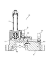
- FIG. 1 shows a schematic diagram of a diaphragm valve 1 according to one embodiment of the present invention.
- the diaphragm valve 1 As shown in FIG. 1, the diaphragm valve 1 according to the present embodiment includes a valve body 16, a diaphragm 17, and a driving unit 12.
- the valve body 16 has a substantially block shape, and has an upstream passage 16a and a downstream passage 16b therein.
- the upstream flow passage 16a opens at the center of the bottom surface of the diaphragm arrangement portion 16d, which is a shallow counterbore-shaped depression formed on the upper surface of the valve body 16, and the periphery of this opening rises in an annular shape to provide a valve seat 16e. Is formed.
- the downstream flow path 16b is open to the periphery of the bottom surface of the diaphragm arrangement portion 16d.
- the diaphragm 17 is a spherical shell-like member in which a central portion of a thin metal plate such as a special stainless steel plate or a nickel-cobalt alloy thin plate is bulged upward, and the diaphragm 17 is provided on the diaphragm arrangement portion 16 d on the upper surface of the valve body 16. Are located.
- An annular holding adapter 18 is arranged on the outer peripheral edge of the diaphragm 17, the lower end of the bonnet 10 abuts from above, and the bonnet 10 is fastened together with the support plate 3 to the valve body 16 by bolts.
- the diaphragm 17 is fixed, and the diaphragm arrangement portion 16d is hermetically sealed.
- the upstream side flow path 16a communicates with the diaphragm arrangement portion 16d sealed by the diaphragm 17 through this gap, and further has a downstream side flow path.
- a flow path communicating with 16b is formed.
- the drive unit 12 includes the bonnet 10, the support plate 3, the piezoelectric actuator 2, the displacement transmitting mechanism (4, 7, 6, 5, 5b), the stem 8, and the disc spring 9.
- the bonnet 10 and the support plate 3 hold the piezoelectric actuator 2, the displacement transmitting mechanisms (4, 7, 6, 5, 5b) and the stem 8 so as to be displaceable in the axial direction. Also, they are fastened together to the valve body 16 with two bolts.
- the bonnet 10 also serves to fix the diaphragm 17 to the valve body 16 as described above.
- the piezoelectric actuator 2 has a built-in piezoelectric element (not shown) stacked in a cylindrical case 2c.
- the case 2c is made of a metal such as a stainless alloy, and has a hemispherical end face on the distal end 2a side and an end face on the base end 2b side closed.
- a voltage to the stacked piezoelectric elements to extend the case 2c, the end surface of the case 2c on the tip 2a side is elastically deformed, and the hemispherical tip 2a is displaced in the longitudinal direction. That is, by applying a voltage to the stacked piezoelectric elements, the entire length of the case 2c from the distal end 2a to the proximal end 2b increases.
- the piezoelectric actuator 2 is disposed vertically so that the tip 2 a is in contact with the support plate 3.
- the tip of the tip 2a has a hemispherical shape, and in this embodiment, falls into a conical depression formed on the upper surface of the support plate.
- the base end portion 2b of the piezoelectric actuator 2 is fitted and held by a pressing member 4 which is a receiving portion of the displacement transmission mechanism (4, 7, 6, 5, 5b).
- the upper surface of the pressing member 4 is in contact with the tip of the adjusting screw 7 screwed into the screw hole of the upper connecting member 6.
- the upper connecting member 6 has a substantially U-shape in which a bottomed cylinder is turned down and both sides are cut, and a pair of displacement transmitting members are connected to the inside thereof by screws.
- the pair of displacement transmitting members 5 are formed of a metal material such as an invar material having a small coefficient of thermal expansion, and have a form in which a cylindrical member along the outer peripheral surface of the piezoelectric actuator 2 is divided into two along the longitudinal direction. .
- Each of the pair of displacement transmitting members 5 has a support plate 3 inserted into each of the openings 5a and extends below the support plate 3, and a locking portion 5b is formed at a tip portion.
- the stem 8 is disposed coaxially with the piezoelectric actuator 2 below the support plate 3 through the guide hole 10a of the bonnet 10, and is provided movably in the axial direction guided by the guide hole 10a. .
- the stem 8 includes arm portions 8a with which the locking portions 5b formed at the lower end portions of the pair of displacement transmitting members 5 respectively engage.
- the stem 8 is urged downward by a disc spring 9.
- the piezoelectric actuator 2 is extended, the stem 8 is also pulled up by the pair of displacement transmitting members 5 against the urging force of the disc spring 9.
- a diaphragm retainer 19 is attached to the distal end (lower end) of the stem 8 and is in contact with the diaphragm 17.
- a resin sleeve 15 is used instead of the conventional O-ring 14 (see FIG. 5) in the sliding portion between the stem 8 and the guide hole 10a of the bonnet 10. That is, the stem 8 is guided by the inner periphery of the sleeve 15 whose outer periphery is fitted and fixed in the guide hole 10a of the bonnet 10. Since the sleeve 15 is formed of a self-lubricating resin such as polyacetal, ultra-high molecular weight polyethylene, fluorine resin, Teflon (registered trademark) resin, and phenol resin, the sleeve 15 has a coefficient of friction with the guided stainless steel stem 8. small. Further, the combination of the outer periphery of the stem 8 and the inner periphery of the sleeve 15 has a cylindrical contact surface, so that the contact area is large and high guide rigidity can be obtained.
- a self-lubricating resin such as polyacetal, ultra-high molecular weight polyethylene, fluorine resin, Tef
- the length of the piezoelectric actuator 2 is the initial length, and the piezoelectric actuator 2 is engaged with the displacement transmitting mechanism (4, 7, 6, 5, 5b).
- the stem 8 is pushed down by the disc spring 9 and is at the lowest position. Therefore, the diaphragm 17 is pressed by the stem 8 and comes into close contact with the valve seat 16e, and the valve is fully closed.
- the stem 8 can move up and down smoothly. Further, since the resin sleeve 15 has a high guide rigidity, it is possible to reduce an increase in the stress of the diaphragm 17 due to the shaft shake without causing the shaft shake at the time of the vertical movement, so that the life of the diaphragm 17 can be improved. it can.
- the outer periphery of the stem 8 is slid on the inner periphery of the resin sleeve 15 whose outer periphery is fitted in the guide hole 10a of the bonnet 10.
- the present invention is not limited to this.
- the outer circumference of the resin sleeve 15 having the inner circumference fitted to the outer circumference may slide on the inner circumference of the guide hole 10 a of the bonnet 10. Even with such a configuration, a low coefficient of friction and high guide rigidity can be obtained.
- FIG. 2 is a schematic sectional view of a flow rate control device according to an embodiment of the present invention, and shows a pressure type flow rate control device 20 in which the above-described diaphragm valve 1 is incorporated.
- a cover or a substrate for feedback control which covers the entire flow control device 20 actually exists, but is not shown for convenience of explanation.
- the flow control device 20 includes a downstream block 25, a pressure detector 22, an orifice 21, a pressure detector 26, and a flow path 25a in addition to the components of the diaphragm valve 1 described above.
- An orifice 21 (a gasket-type orifice in the present embodiment) is provided inside the valve body 16 in a flow path on the downstream side of the diaphragm 17.
- an upstream pressure detector 22 for detecting pressure is provided in the middle of the flow path 16b on the upstream side of the orifice 21, an upstream pressure detector 22 for detecting pressure is provided.
- the downstream block 25 is connected to the valve body 16 by bolts, has a downstream flow path 25a communicating with a flow path 16b on the downstream side of the valve body 16, and detects a pressure in the downstream flow path 25a.
- the opening and closing of the diaphragm valve 1 is controlled by PID control based on the detection values of the pressure detectors 22 and 26 by a control device (not shown).
- the life of the fluid control device can be expected to be prolonged due to the prolongation of the life of the diaphragm valve.
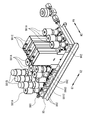
- FIG. 3 is a schematic perspective view of the fluid control device according to one embodiment of the present invention.
- the fluid control device shown in FIG. 3 is provided with a metal base plate BS arranged along the width directions W1 and W2 and extending in the longitudinal directions G1 and G2. Note that W1 indicates the front side, W2 indicates the back side, G1 indicates the upstream side, and G2 indicates the downstream side.
- Various fluid devices 991A to 991E are installed on the base plate BS via a plurality of flow path blocks 992.
- the flow path (not shown) through which the fluid flows from the upstream side G1 to the downstream side G2 passes through the plurality of flow path blocks 992. Roads are respectively formed.
- the “fluid device” is a device used in a fluid control device that controls the flow of a fluid, and includes a body that defines a fluid flow path, and at least two flow paths that are opened on the surface of the body. It is a device having. Specifically, an on-off valve (two-way valve) 991A, a regulator 991B, a pressure gauge 991C, an on-off valve (three-way valve) 991D, a mass flow controller 991E, and the like are included, but not limited thereto.
- the introduction pipe 993 is connected to a flow path port on the upstream side of the flow path (not shown).
- the present invention is applicable to various diaphragm valves such as the above-described on-off valves 991A and 991D, regulator 991B, and mass flow controller 991E.
- FIG. 4 is a block diagram of a semiconductor manufacturing apparatus according to one embodiment of the present invention.
- a semiconductor manufacturing apparatus 980 shown in FIG. 4 is an apparatus for executing a semiconductor manufacturing process by an atomic layer deposition method (ALD: Atomic Layer Deposition method), 981 is a process gas supply source, and 982 is a gas box (fluid control device). ) And 983, a tank, 984, an opening / closing valve, 985, a control unit, 986, a processing chamber, and 987, an exhaust pump.
- ALD Atomic Layer Deposition method
- 981 is a process gas supply source
- 982 is a gas box (fluid control device).
- the present invention is applicable to the gas box 982 described above, the fluid device constituting the gas box 982, and the on-off valve 984.
- the present invention is not limited to the above-described embodiment.
- a person skilled in the art can make various additions and changes without departing from the scope of the present invention.
- the present invention is not limited to this.
- the present invention is applied to a precision method such as an atomic layer etching method (ALE: Atomic Layer Etching method). It can be applied to any object that needs precise flow control.
- ALE Atomic Layer Etching method
- the opening and closing valve 984 is arranged outside the gas box 982 as a fluid control device.
- various fluid devices such as an opening and closing valve, a regulator, a mass flow controller and the like are integrated and stored in the box. It is also possible for the device to include the diaphragm valve of the above embodiment.
- Diaphragm valve 2 Piezoelectric actuator 2a: Tip 2b: Base 2c: Case 3: Support plate 4: Pressing member 5: Displacement transmitting member 6: Upper connecting member 7: Adjusting screw 8: Stem 8a: Arm 9 : Disc spring 10: Bonnet 10a: Guide hole 10b: Through hole 12: Drive unit 14: O-ring 15: Sleeve 16: Valve body 16a: Upstream flow path 16b: Downstream flow path 16d: Diaphragm arrangement section 16e: Valve seat 17: Diaphragm 18: Holder adapter 19: Diaphragm holder 20: Flow control device 21: Orifice 22: Pressure detector 25: Downstream block 25a: Downstream flow path 26: Pressure detector 980: Semiconductor manufacturing device 981: Process gas supply Source 982: Gas Box 983: Tank 984: on-off valve 985: control unit 986: a processing chamber 987: exhaust pump 991A ⁇ 991E: fluid device 992: the passage block 993: inlet pipe BS: base plate
Landscapes
- Engineering & Computer Science (AREA)
- General Engineering & Computer Science (AREA)
- Mechanical Engineering (AREA)
- Physics & Mathematics (AREA)
- General Physics & Mathematics (AREA)
- Automation & Control Theory (AREA)
- Electrically Driven Valve-Operating Means (AREA)
- Flow Control (AREA)
- Valve Housings (AREA)
Abstract
Description
前記複数の流体機器は、上記構成のダイヤフラムバルブ又は流量制御装置を含むものである。
ステム8の先端(下端)には、ダイヤフラム押え19が取り付けられてダイヤフラム17に当接している。
図2は、本発明の一実施形態に係る流量制御装置の概略断面図であり、上記したダイヤフラムバルブ1が組み込まれた圧力式の流量制御装置20を示す。
図2において、流量制御装置20の全体を覆うカバーやフィードバック制御用の基板が実際には存在するが、説明の便宜上図示していない。
流量制御装置20は、上記したダイヤフラムバルブ1の構成要素に加えて、下流側ブロック25、圧力検出器22、オリフィス21、圧力検出器26、流路25aを有する。
下流側ブロック25は、バルブボディ16にボルトにより連結され、バルブボディ16の下流側の流路16bに連通する下流側流路25aを有し、下流側流路25a内の圧力を検出する下流側の圧力検出器26が設けられている。
図示しない制御装置により、各圧力検出器22、26の検出値に基づいてダイヤフラムバルブ1がPID制御により開閉制御される。
図3は、本発明の一実施形態に係る流体制御装置の概略斜視図である。
図3に示す流体制御装置には、幅方向W1、W2に沿って配列され長手方向G1、G2に延びる金属製のベースプレートBSが設けられている。なお、W1は正面側、W2は背面側、G1は上流側、G2は下流側の方向を示している。ベースプレートBSには、複数の流路ブロック992を介して各種流体機器991A~991Eが設置され、複数の流路ブロック992には、上流側G1から下流側G2に向かって流体が流通する図示しない流路がそれぞれ形成されている。
図4は、本発明の一実施形態に係る半導体製造装置のブロック図である。
図4に示す半導体製造装置980は、原子層堆積法(ALD:Atomic Layer Deposition法)による半導体製造プロセスを実行するための装置であり、981はプロセスガス供給源、982はガスボックス(流体制御装置)、983はタンク、984は開閉バルブ、985は制御部、986は処理チャンバ、987は排気ポンプを示している。
2 :圧電アクチュエータ
2a :先端部
2b :基端部
2c :ケース
3 :支持プレート
4 :押圧部材
5 :変位伝達部材
6 :上部連結部材
7 :調整ねじ
8 :ステム
8a :アーム部
9 :皿ばね
10 :ボンネット
10a :ガイド孔
10b :貫通孔
12 :駆動部
14 :Oリング
15 :スリーブ
16 :バルブボディ
16a :上流側流路
16b :下流側流路
16d :ダイヤフラム配置部
16e :バルブシート
17 :ダイヤフラム
18 :押えアダプタ
19 :ダイヤフラム押え
20 :流量制御装置
21 :オリフィス
22 :圧力検出器
25 :下流側ブロック
25a :下流側流路
26 :圧力検出器
980 :半導体製造装置
981 :プロセスガス供給源
982 :ガスボックス
983 :タンク
984 :開閉バルブ
985 :制御部
986 :処理チャンバ
987 :排気ポンプ
991A~991E :流体機器
992 :流路ブロック
993 :導入管
BS :ベースプレート
GI、G2:長手方向
W1、W2:幅方向
Claims (6)
- 内部に流路を有し、一面にダイヤフラム配置部を有するバルブボディと、前記ダイヤフラム配置部に配置され、弾性変形により前記流路の開閉及び開度の調節が可能なダイヤフラムと、前記ダイヤフラムを押圧して弾性変形させるステム及び該ステムを駆動するアクチュエータを有する駆動部と、を有するダイヤフラムバルブにおいて、
前記ステムは、前記バルブボディに固定されたボンネットにより、樹脂製のスリーブを介して軸方向に変位可能に保持されていることを特徴とする、ダイヤフラムバルブ。 - 前記樹脂製のスリーブは、ポリアセタール、超高分子量ポリエチレン、フッ素樹脂、フェノール樹脂のいずれかで形成されたものである、請求項1に記載のダイヤフラムバルブ。
- 前記アクチュエータは、圧電アクチュエータである、請求項1又は2に記載のダイヤフラムバルブ。
- 請求項1~3のいずれかに記載のダイヤフラムバルブを有する流量制御装置。
- 複数の流体機器が配列された流体制御装置であって、
前記複数の流体機器は、請求項1~3のいずれかに記載のダイヤフラムバルブ又は請求項4に記載の流量制御装置を含む、流体制御装置。 - 密閉されたチャンバ内においてプロセスガスによる処理工程を要する半導体の製造プロセスにおいて、前記プロセスガスの制御に請求項1~3のいずれかに記載のダイヤフラムバルブ又は請求項4に記載の流量制御装置を用いる、半導体製造装置。
Priority Applications (4)
| Application Number | Priority Date | Filing Date | Title |
|---|---|---|---|
| CN201980064209.5A CN112771294A (zh) | 2018-09-29 | 2019-09-03 | 隔膜阀和流量控制装置 |
| US17/275,034 US11674603B2 (en) | 2018-09-29 | 2019-09-03 | Diaphragm valve and flow rate control device |
| JP2020548270A JP7360719B2 (ja) | 2018-09-29 | 2019-09-03 | ダイヤフラムバルブ及び流量制御装置 |
| KR1020217010731A KR102563815B1 (ko) | 2018-09-29 | 2019-09-03 | 다이어프램 밸브 및 유량 제어 장치 |
Applications Claiming Priority (2)
| Application Number | Priority Date | Filing Date | Title |
|---|---|---|---|
| JP2018186187 | 2018-09-29 | ||
| JP2018-186187 | 2018-09-29 |
Publications (1)
| Publication Number | Publication Date |
|---|---|
| WO2020066491A1 true WO2020066491A1 (ja) | 2020-04-02 |
Family
ID=69950544
Family Applications (1)
| Application Number | Title | Priority Date | Filing Date |
|---|---|---|---|
| PCT/JP2019/034554 Ceased WO2020066491A1 (ja) | 2018-09-29 | 2019-09-03 | ダイヤフラムバルブ及び流量制御装置 |
Country Status (6)
| Country | Link |
|---|---|
| US (1) | US11674603B2 (ja) |
| JP (1) | JP7360719B2 (ja) |
| KR (1) | KR102563815B1 (ja) |
| CN (1) | CN112771294A (ja) |
| TW (1) | TWI706100B (ja) |
| WO (1) | WO2020066491A1 (ja) |
Cited By (2)
| Publication number | Priority date | Publication date | Assignee | Title |
|---|---|---|---|---|
| KR20230094961A (ko) | 2021-12-21 | 2023-06-28 | 가부시키가이샤 호리바 에스텍 | 유체 제어 장치, 기화 시스템, 및 피에조 액추에이터 |
| KR20230138823A (ko) * | 2022-03-24 | 2023-10-05 | (주)케이엔알시스템 | 유압 제어 밸브 및 유압 제어 밸브를 포함하는 유압 구동 시스템 |
Families Citing this family (3)
| Publication number | Priority date | Publication date | Assignee | Title |
|---|---|---|---|---|
| JP7045738B1 (ja) * | 2021-03-23 | 2022-04-01 | 株式会社リンテック | 常時閉型流量制御バルブ |
| JP2024158472A (ja) * | 2023-04-27 | 2024-11-08 | 株式会社堀場エステック | 流体制御弁及び流体制御装置 |
| WO2025054266A1 (en) * | 2023-09-06 | 2025-03-13 | Equilibar, Llc | Flow control valve with diaphragm movement feedback |
Citations (8)
| Publication number | Priority date | Publication date | Assignee | Title |
|---|---|---|---|---|
| JPH0666389A (ja) * | 1992-08-19 | 1994-03-08 | Yamatake Honeywell Co Ltd | 調節弁 |
| JPH11154022A (ja) * | 1997-04-08 | 1999-06-08 | Hitachi Metals Ltd | マスフローコントローラ及びその運転制御方法 |
| JP2003042324A (ja) * | 2001-07-27 | 2003-02-13 | Matsushita Electric Ind Co Ltd | 遮断弁 |
| WO2012147477A1 (ja) * | 2011-04-27 | 2012-11-01 | シーケーディ株式会社 | 複層ダイアフラム |
| WO2013046660A1 (ja) * | 2011-09-30 | 2013-04-04 | 株式会社フジキン | ガス供給装置 |
| JP2014504355A (ja) * | 2010-12-09 | 2014-02-20 | ソシエテ ベ イ セ | ライターのためのバルブ組立体及びこのようなバルブ組立体を備えるガスライター |
| CN204213431U (zh) * | 2014-09-28 | 2015-03-18 | 杭州金奥阀门制造有限公司 | 微小流量阀 |
| WO2017033423A1 (ja) * | 2015-08-21 | 2017-03-02 | 株式会社フジキン | 圧電式リニアアクチュエータ、圧電駆動バルブ及び流量制御装置 |
Family Cites Families (10)
| Publication number | Priority date | Publication date | Assignee | Title |
|---|---|---|---|---|
| US3806084A (en) * | 1971-06-21 | 1974-04-23 | Scm Corp | Improved valve dispensing apparatus |
| US4171792A (en) * | 1974-12-23 | 1979-10-23 | Dresser Industries, Inc. | High pressure diaphragm valves |
| US4019534A (en) * | 1975-10-06 | 1977-04-26 | Will Ross, Inc. | Needle valve assembly |
| JPS6066389A (ja) * | 1983-09-22 | 1985-04-16 | Fujitsu Ltd | 半導体記憶装置 |
| JPS63115970A (ja) * | 1986-10-31 | 1988-05-20 | Motoyama Seisakusho:Kk | ダイヤフラム弁 |
| KR930001721B1 (ko) * | 1988-03-02 | 1993-03-12 | 도또기끼 가부시끼가이샤 | 대변기 세정장치 |
| US6062246A (en) | 1997-04-08 | 2000-05-16 | Hitachi Metals Ltd. | Mass flow controller and operating method thereof |
| JP4743763B2 (ja) * | 2006-01-18 | 2011-08-10 | 株式会社フジキン | 圧電素子駆動式金属ダイヤフラム型制御弁 |
| JP6141663B2 (ja) | 2013-03-27 | 2017-06-07 | 株式会社堀場エステック | 流体制御弁 |
| JP6231463B2 (ja) * | 2014-11-07 | 2017-11-15 | 株式会社鷺宮製作所 | カシメ構造体 |
-
2019
- 2019-09-03 KR KR1020217010731A patent/KR102563815B1/ko active Active
- 2019-09-03 US US17/275,034 patent/US11674603B2/en active Active
- 2019-09-03 JP JP2020548270A patent/JP7360719B2/ja active Active
- 2019-09-03 WO PCT/JP2019/034554 patent/WO2020066491A1/ja not_active Ceased
- 2019-09-03 CN CN201980064209.5A patent/CN112771294A/zh active Pending
- 2019-09-25 TW TW108134508A patent/TWI706100B/zh active
Patent Citations (8)
| Publication number | Priority date | Publication date | Assignee | Title |
|---|---|---|---|---|
| JPH0666389A (ja) * | 1992-08-19 | 1994-03-08 | Yamatake Honeywell Co Ltd | 調節弁 |
| JPH11154022A (ja) * | 1997-04-08 | 1999-06-08 | Hitachi Metals Ltd | マスフローコントローラ及びその運転制御方法 |
| JP2003042324A (ja) * | 2001-07-27 | 2003-02-13 | Matsushita Electric Ind Co Ltd | 遮断弁 |
| JP2014504355A (ja) * | 2010-12-09 | 2014-02-20 | ソシエテ ベ イ セ | ライターのためのバルブ組立体及びこのようなバルブ組立体を備えるガスライター |
| WO2012147477A1 (ja) * | 2011-04-27 | 2012-11-01 | シーケーディ株式会社 | 複層ダイアフラム |
| WO2013046660A1 (ja) * | 2011-09-30 | 2013-04-04 | 株式会社フジキン | ガス供給装置 |
| CN204213431U (zh) * | 2014-09-28 | 2015-03-18 | 杭州金奥阀门制造有限公司 | 微小流量阀 |
| WO2017033423A1 (ja) * | 2015-08-21 | 2017-03-02 | 株式会社フジキン | 圧電式リニアアクチュエータ、圧電駆動バルブ及び流量制御装置 |
Cited By (4)
| Publication number | Priority date | Publication date | Assignee | Title |
|---|---|---|---|---|
| KR20230094961A (ko) | 2021-12-21 | 2023-06-28 | 가부시키가이샤 호리바 에스텍 | 유체 제어 장치, 기화 시스템, 및 피에조 액추에이터 |
| KR20230138823A (ko) * | 2022-03-24 | 2023-10-05 | (주)케이엔알시스템 | 유압 제어 밸브 및 유압 제어 밸브를 포함하는 유압 구동 시스템 |
| KR102750194B1 (ko) * | 2022-03-24 | 2025-01-07 | (주)케이엔알시스템 | 유압 제어 밸브 및 유압 제어 밸브를 포함하는 유압 구동 시스템 |
| KR102916186B1 (ko) | 2022-03-24 | 2026-01-22 | (주)케이엔알시스템 | 유압 제어 밸브 및 유압 제어 밸브를 포함하는 유압 구동 시스템 |
Also Published As
| Publication number | Publication date |
|---|---|
| CN112771294A (zh) | 2021-05-07 |
| TW202012819A (zh) | 2020-04-01 |
| US11674603B2 (en) | 2023-06-13 |
| JP7360719B2 (ja) | 2023-10-13 |
| KR20210049933A (ko) | 2021-05-06 |
| US20220057002A1 (en) | 2022-02-24 |
| JPWO2020066491A1 (ja) | 2021-09-02 |
| KR102563815B1 (ko) | 2023-08-03 |
| TWI706100B (zh) | 2020-10-01 |
Similar Documents
| Publication | Publication Date | Title |
|---|---|---|
| WO2020066491A1 (ja) | ダイヤフラムバルブ及び流量制御装置 | |
| US10132415B2 (en) | Fluid controller | |
| KR102398907B1 (ko) | 밸브 장치 | |
| KR20190015568A (ko) | 유체 제어 밸브 | |
| KR20210027452A (ko) | 밸브 장치 | |
| CN112469934A (zh) | 阀装置、流体控制装置、流体控制方法、半导体制造装置以及半导体制造方法 | |
| US11598430B2 (en) | Valve device, flow rate control method, fluid control device, semiconductor manufacturing method, and semiconductor manufacturing apparatus using the valve device | |
| US20210239230A1 (en) | Piezoelectric driven valve, pressure-type flow rate control device, and vaporization supply device | |
| JP7529287B2 (ja) | ダイヤフラムバルブ、流量制御装置、流体制御装置、及び半導体製造装置 | |
| US6637451B2 (en) | Pneumatic pressure regulator assembly | |
| KR102304548B1 (ko) | 밸브장치 및 그 제어장치를 사용한 제어방법, 유체 제어장치 및 반도체 제조장치 | |
| JP7352971B2 (ja) | バルブ装置、流量制御方法、流体制御装置、半導体製造方法、および半導体製造装置 | |
| US11174949B2 (en) | Actuator and valve device using the same | |
| JP7382054B2 (ja) | バルブ装置および流量制御装置 | |
| JP7187015B2 (ja) | ダイヤフラムバルブ及び流量制御装置 | |
| JP2020034135A (ja) | ダイヤフラムバルブ及び流量制御装置 | |
| CN104797997B (zh) | 控制阀 | |
| JP7166599B2 (ja) | ダイヤフラムバルブおよび流量制御装置 | |
| WO2024135843A1 (ja) | 連動型定圧弁 | |
| JP2025157768A (ja) | 流体制御弁 | |
| JP2023148578A (ja) | ダイヤフラムバルブ |
Legal Events
| Date | Code | Title | Description |
|---|---|---|---|
| 121 | Ep: the epo has been informed by wipo that ep was designated in this application |
Ref document number: 19867358 Country of ref document: EP Kind code of ref document: A1 |
|
| ENP | Entry into the national phase |
Ref document number: 2020548270 Country of ref document: JP Kind code of ref document: A |
|
| NENP | Non-entry into the national phase |
Ref country code: DE |
|
| ENP | Entry into the national phase |
Ref document number: 20217010731 Country of ref document: KR Kind code of ref document: A |
|
| 122 | Ep: pct application non-entry in european phase |
Ref document number: 19867358 Country of ref document: EP Kind code of ref document: A1 |