WO2020066226A1 - 焼灼穿刺針 - Google Patents
焼灼穿刺針 Download PDFInfo
- Publication number
- WO2020066226A1 WO2020066226A1 PCT/JP2019/027533 JP2019027533W WO2020066226A1 WO 2020066226 A1 WO2020066226 A1 WO 2020066226A1 JP 2019027533 W JP2019027533 W JP 2019027533W WO 2020066226 A1 WO2020066226 A1 WO 2020066226A1
- Authority
- WO
- WIPO (PCT)
- Prior art keywords
- puncture needle
- tip
- hole
- cautery
- tip electrode
- Prior art date
- Legal status (The legal status is an assumption and is not a legal conclusion. Google has not performed a legal analysis and makes no representation as to the accuracy of the status listed.)
- Ceased
Links
Images


Classifications
-
- A—HUMAN NECESSITIES
- A61—MEDICAL OR VETERINARY SCIENCE; HYGIENE
- A61B—DIAGNOSIS; SURGERY; IDENTIFICATION
- A61B18/00—Surgical instruments, devices or methods for transferring non-mechanical forms of energy to or from the body
- A61B18/04—Surgical instruments, devices or methods for transferring non-mechanical forms of energy to or from the body by heating
- A61B18/12—Surgical instruments, devices or methods for transferring non-mechanical forms of energy to or from the body by heating by passing a current through the tissue to be heated, e.g. high-frequency current
- A61B18/14—Probes or electrodes therefor
- A61B18/1477—Needle-like probes
-
- A—HUMAN NECESSITIES
- A61—MEDICAL OR VETERINARY SCIENCE; HYGIENE
- A61B—DIAGNOSIS; SURGERY; IDENTIFICATION
- A61B17/00—Surgical instruments, devices or methods
- A61B17/34—Trocars; Puncturing needles
- A61B17/3478—Endoscopic needles, e.g. for infusion
-
- A—HUMAN NECESSITIES
- A61—MEDICAL OR VETERINARY SCIENCE; HYGIENE
- A61B—DIAGNOSIS; SURGERY; IDENTIFICATION
- A61B18/00—Surgical instruments, devices or methods for transferring non-mechanical forms of energy to or from the body
- A61B2018/00315—Surgical instruments, devices or methods for transferring non-mechanical forms of energy to or from the body for treatment of particular body parts
- A61B2018/00345—Vascular system
- A61B2018/00351—Heart
- A61B2018/00357—Endocardium
-
- A—HUMAN NECESSITIES
- A61—MEDICAL OR VETERINARY SCIENCE; HYGIENE
- A61B—DIAGNOSIS; SURGERY; IDENTIFICATION
- A61B18/00—Surgical instruments, devices or methods for transferring non-mechanical forms of energy to or from the body
- A61B2018/00571—Surgical instruments, devices or methods for transferring non-mechanical forms of energy to or from the body for achieving a particular surgical effect
- A61B2018/00595—Cauterization
Definitions
- the present invention relates to a medical cautery puncture needle used for cauterizing and puncturing a treatment section with high frequency (radio wave).
- a catheter puncture needle having a sharp needle disposed at the tip thereof is used.
- a cautery puncture needle having an electrode for generating a high-frequency current at its tip has been proposed (see Patent Document 1).
- a puncture needle having a needle at its tip a mechanical pressing force is applied by a needle to a target treatment section such as a membrane portion to make a hole.
- a cautery puncture needle is used, the electrode is brought into contact with a target treatment section such as a film-like portion, and a high-frequency current is supplied to the electrode. As a result, Joule heat is generated in the living body and a hole can be formed in the membrane by cauterization.
- a puncture needle for cauterization in which an injection hole for injecting a contrast agent is formed in a portion covered with an insulating layer on the base end side of a tip electrode (see Patent Document 2).
- JP 2008-237620 A JP-T-2015-518752
- the present invention has been made in view of such circumstances, and it is an object of the present invention to make it difficult to cause inconvenience such as damaging peripheral tissues in a living body, and to achieve the object in membrane tissues such as atrial septum. It is an object of the present invention to provide a cautery puncture needle that can easily puncture a narrow portion to be formed and that can easily confirm that the tip has reached the opposite side of the membrane tissue.
- a first aspect of the present invention is a metal hollow pipe having a hollow portion communicating in the longitudinal direction, and a tip electrode portion provided with a high-frequency current, which is integrally provided at a tip of the hollow pipe, A cautery puncture needle, wherein a hole communicating with the hollow portion is formed on a side surface of the tip electrode portion.
- the cautery puncture needle according to the first aspect wherein the tip of the tip electrode portion has a semi-elliptical spherical shape.
- a third aspect of the present invention is the cautery puncture needle according to the second aspect, wherein the outer diameter of the tip electrode portion is 0.4 to 0.9 mm.
- a fourth aspect of the present invention is the cautery puncture needle according to any one of the first to third aspects, wherein the opening of the hole has an elliptical or elliptical shape extending in the longitudinal direction.
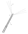
- FIG. 1 is a partial perspective view schematically showing one embodiment of a cautery puncture needle of the present invention.
- FIG. 9 is a partial perspective view schematically showing another embodiment of the cautery puncture needle of the present invention.
- FIG. 2 is a partial side view schematically showing one embodiment of the cautery puncture needle of the present invention.
- 1 is an overall perspective view schematically showing one embodiment of a cautery puncture needle of the present invention. It is a fragmentary sectional view showing an example of a state of ejection of liquid from a hole.
- FIG. 9 is a partial cross-sectional view showing another example of a state in which a liquid is ejected from a hole.
- FIG. 1 is a partial cross-sectional view schematically showing one embodiment of the cautery puncture needle of the present invention.
- FIG. 2 is a partial perspective view schematically showing one embodiment of the cautery puncture needle of the present invention.
- the cautery puncture needle 10 of the present embodiment includes a metal hollow pipe 15 having a hollow portion 2 communicating in the longitudinal direction, and a tip electrode portion 7.
- the tip electrode section 7 is integrally provided at the tip of the hollow pipe 15, and is configured to generate Joule heat in a living body when a high-frequency current is applied.
- FIG. 5 is an overall perspective view schematically showing one embodiment of the cautery puncture needle of the present invention.
- a luer connector 46 having a relay cable 42 and a syringe connection portion 44 is disposed on the operation base end side of the cautery puncture needle 10.
- the relay cable 42 is a means for electrically connecting the generation source of the high frequency (radio wave (RF)) current to the hollow pipe 15 and the tip electrode 7.
- RF radio wave
- the syringe connecting portion 44 is a luer taper fitting portion to which the syringe is connected. If the syringe filled with the contrast agent is connected to the syringe connection portion 44 and the contrast agent is injected into the hollow portion, the medicinal solution is ejected from the hole 9 (FIG. 1) formed on the side surface of the tip electrode portion 7 to the outside. Can be. That is, the hole formed on the side surface of the tip electrode portion functions as an injection hole for injecting a chemical such as a contrast agent to the outside.
- a hole 9 functioning as an ejection hole for ejecting a contrast agent is formed on a side surface of the tip electrode portion 7 closer to the insertion tip 12 (FIGS. 1 and 2). That is, according to the cautery puncture needle 10 of the present embodiment, since the contrast medium can be ejected from the hole 9 provided at a position closer to the insertion tip 12 into the living body, the tip electrode section 7 is connected to the atrial septum or the like. Can be easily confirmed to have reached the opposite side of the membrane tissue.
- FIG. 3 is a partial perspective view schematically showing another embodiment of the cautery puncture needle of the present invention.
- the cautery puncture needle 20 shown in FIG. 3 includes a hollow pipe 25 made of metal and a tip electrode 17.
- a hole 19 whose opening shape is a perfect circle is formed on the side surface of the tip electrode portion 17 and communicates with the hollow portion in the hollow pipe 25.
- the opening shape of the hole 9 is preferably an elliptical shape or an elliptical shape extending in the longitudinal direction of the hollow pipe 15.
- FIG. 6 is a partial cross-sectional view showing an example of a state in which a liquid is ejected from a hole.
- FIG. 7 is a partial cross-sectional view showing another example of a state in which the liquid is ejected from the holes.
- the opening shape of the hole 9 of the cautery puncture needle 10 shown in FIG. 6 is an oval shape extending in the longitudinal direction of the hollow pipe (FIGS. 1 and 2).
- the opening shape of the hole 19 of the cautery puncture needle 20 shown in FIG. 7 is a perfect circle (FIG. 3).
- the cautery puncture needle 10 FIG.
- the liquid contrast agent 14 can be ejected further forward in the insertion direction. That is, when the opening shape of the hole is an elliptical shape or an elliptical shape, the contrast agent can be jetted further forward. Therefore, even if the injection amount of the contrast agent is further reduced, clear imaging can be performed by X-ray fluoroscopy. This makes it possible to more easily confirm that the insertion tip has reached the opposite side of the membrane tissue. Further, since the injection amount of the contrast agent can be reduced, the burden on the living body can be further reduced.
- FIG. 4 is a partial side view schematically showing one embodiment of the cautery puncture needle of the present invention.
- the ratio (L / S ratio) between the major axis L and the minor axis S of the hole 9 is preferably 1.06 to 6.00, More preferably, it is 1.19 to 3.67.
- the number of holes formed in the tip electrode portion is not particularly limited, and is preferably 1 to 4, more preferably 2 or 3. By setting the number of holes formed in the tip electrode portion to two or three, the tip electrode portion can be maintained at a more suitable strength.
- the shape of the insertion tip of the tip electrode portion 7 of the cautery puncture needle 10 is preferably a semi-elliptical sphere (bombshell shape, semi-rugby ball shape).
- the shape of the insertion tip is a semi-elliptical sphere whose outer diameter gradually decreases toward the insertion tip 12, the insertion tip 12 can be more reliably brought into contact with a narrow portion of the membrane tissue such as the atrial septum. In addition, the contact area with the narrow portion to be brought into contact can be further reduced.
- the insertion tip 12 Assuming a case of puncturing the atrial septum, the insertion tip 12 is likely to be misaligned because the heart is in a pulsating state, but if the insertion tip shape is a semi-elliptical sphere, the insertion tip 12 is pressed against the atrial septum. Can be increased. Thereby, the displacement of the insertion tip 12 can be effectively suppressed, the Joule heat can be concentrated on a desired narrow portion in the membrane tissue, and the hole can be formed more reliably.
- the tip electrode portion is made of metal because a high-frequency current is applied.
- the metal forming the tip electrode portion is not particularly limited as long as high-frequency current can be passed through, but it is possible to perform high-contrast imaging with X-ray fluoroscopy so that the position in the surgical site can be easily confirmed.
- Metals are preferred. Specific examples include platinum (Pt), iridium (Ir), alloys thereof (Pt-Ir alloy), and alloys of these metals with stainless steel (Pt-Ir-SUS alloy).
- the hollow pipe 15 is composed of a distal pipe 3 in which the distal electrode section 7 is disposed, and a proximal pipe 5 connected to the proximal end of the distal pipe 3 and having a slightly larger diameter than the distal pipe. ( Figure 1).
- a proximal pipe 5 connected to the proximal end of the distal pipe 3 and having a slightly larger diameter than the distal pipe.
- Hollow pipes are made of metal with good flexibility.
- the metal include stainless steel such as SUS302, SUS304V and SUS316L, and various alloys such as Nitinol and CoCr. Among them, stainless steel such as SUS304V is preferable.
- a coating layer 16 is formed on the surface of the hollow pipe 15 (FIGS. 1 and 2).
- the material forming the coating layer 16 is preferably a hydrophobic resin material. Above all, it is preferable to form the coating layer with a fluororesin such as PTFE, ETFE, and PFA, because the sliding resistance of the cautery puncture needle can be reduced more effectively.
- each part of the tip electrode part 7 are preferably as follows (FIG. 4). That is, the entire length A (the length from the insertion tip 12 to the coating layer 16) of the tip electrode portion 7 is preferably 1.16 to 2.50 mm.
- the length B from the insertion tip 12 to the opening tip of the hole 9 is preferably 0.50 to 1.10 mm.
- the length C from the base end of the hole 9 to the coating layer 16 is preferably 0.30 to 0.80 mm.
- the outer diameter D of the tip electrode portion 7 is preferably 0.4 to 0.9 mm, more preferably 0.5 to 0.8 mm (FIG. 4). Assuming the case of puncturing the atrial septum, it is necessary to inject a contrast agent to confirm that the tip electrode section including the insertion tip of the cautery puncture needle has reached the opposite side (left atrium) of the atrial septum. It may not be desirable. In such a case, if the outer diameter D of the tip electrode portion 7 is within the above range, it is possible to easily determine whether the atrial septum has been punctured by measuring the fluctuations of the right and left atrial pressures. Can be determined.
- the outer diameter D of the tip electrode portion 7 is less than 0.4 mm, it becomes difficult to determine even if a puncture is made into the atrial septum because the fluctuations in the right and left atrial pressures are small.
- the outer diameter D of the tip electrode portion 7 is more than 0.9 mm, the operability tends to decrease and the burden on the living body tends to increase.
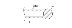
- FIG. 8A to 8D are partial cross-sectional views illustrating a procedure for manufacturing a tip electrode portion.
- a tip pipe 3 made of metal such as stainless steel having a hollow portion 2 and a columnar electrode material 24 are prepared.
- the electrode material 24 is inserted into one open end and fitted.
- the electrode material 24 is, for example, a metal member such as a Pt-Ir alloy.
- the fitted electrode material 24 and the open end of the distal end pipe 3 are welded by arc welding such as plasma welding or Tig welding to form a welded end 26 as shown in FIG. 8B.
- the formed welded end 26 is an alloy of the metal constituting the tip pipe 3 and the metal constituting the electrode material 24 (FIG. 8A). Further, the welded end 26 formed by the above-described welding is substantially seamlessly joined to the distal end pipe 3 (hollow pipe 15).
- the tip electrode portion 7 having a desired shape such as a semi-elliptical sphere as shown in FIG. 8C can be formed.
- the tip electrode portion 7 as shown in FIG. 8D can be formed.
- the tip electrode portion 7 formed in this manner since the hollow pipe 15 and the insertion tip 12 are substantially seamlessly joined to each other, problems such as the insertion tip 12 falling off during use may occur. Hard and safe.
- the hollow pipe 15 and the insertion tip 12 are formed by being seamlessly joined to each other, the supplied high-frequency current does not stop and power loss can be reduced.
- an adhesive binder is applied on the outer peripheral surface of the hollow pipe, and the hollow pipe is inserted into a heat-shrinkable tube made of fluororesin such as PTFE. Then, if the heat-shrinkable tube is shrunk by moderate heating, the coating layer can be formed in close contact with a predetermined portion on the outer peripheral surface of the hollow pipe. Then, as shown in FIG. 5, a desired portion of the hollow pipe 15 is bent to form a bent portion 32, and an operation unit such as a luer connector 46 is connected to the operation base end of the hollow pipe 15, thereby obtaining The cautery puncture needle 10 of the embodiment can be obtained.
- the ablation puncture needle of the present invention is useful, for example, as a puncture needle for puncturing the atrial septum separating the right atrium and the left atrium.
Landscapes
- Health & Medical Sciences (AREA)
- Surgery (AREA)
- Engineering & Computer Science (AREA)
- Life Sciences & Earth Sciences (AREA)
- Biomedical Technology (AREA)
- Molecular Biology (AREA)
- Nuclear Medicine, Radiotherapy & Molecular Imaging (AREA)
- Plasma & Fusion (AREA)
- Physics & Mathematics (AREA)
- Heart & Thoracic Surgery (AREA)
- Medical Informatics (AREA)
- Otolaryngology (AREA)
- Animal Behavior & Ethology (AREA)
- General Health & Medical Sciences (AREA)
- Public Health (AREA)
- Veterinary Medicine (AREA)
- Surgical Instruments (AREA)
- Media Introduction/Drainage Providing Device (AREA)
Priority Applications (4)
| Application Number | Priority Date | Filing Date | Title |
|---|---|---|---|
| CN202510311624.3A CN120000321A (zh) | 2018-09-28 | 2019-07-11 | 烧灼穿刺针 |
| EP19864134.2A EP3858273A4 (en) | 2018-09-28 | 2019-07-11 | CAUTERY PUNCTION NEEDLE |
| CN201980058888.5A CN112672708A (zh) | 2018-09-28 | 2019-07-11 | 烧灼穿刺针 |
| US17/278,906 US20220031383A1 (en) | 2018-09-28 | 2019-07-11 | Cautery puncture needle |
Applications Claiming Priority (2)
| Application Number | Priority Date | Filing Date | Title |
|---|---|---|---|
| JP2018-183150 | 2018-09-28 | ||
| JP2018183150A JP7165009B2 (ja) | 2018-09-28 | 2018-09-28 | 焼灼穿刺針 |
Publications (1)
| Publication Number | Publication Date |
|---|---|
| WO2020066226A1 true WO2020066226A1 (ja) | 2020-04-02 |
Family
ID=69952558
Family Applications (1)
| Application Number | Title | Priority Date | Filing Date |
|---|---|---|---|
| PCT/JP2019/027533 Ceased WO2020066226A1 (ja) | 2018-09-28 | 2019-07-11 | 焼灼穿刺針 |
Country Status (5)
| Country | Link |
|---|---|
| US (1) | US20220031383A1 (https=) |
| EP (1) | EP3858273A4 (https=) |
| JP (1) | JP7165009B2 (https=) |
| CN (2) | CN112672708A (https=) |
| WO (1) | WO2020066226A1 (https=) |
Cited By (1)
| Publication number | Priority date | Publication date | Assignee | Title |
|---|---|---|---|---|
| EP4295886A4 (en) * | 2021-02-22 | 2024-12-25 | Kaneka Corporation | Puncturing device |
Families Citing this family (5)
| Publication number | Priority date | Publication date | Assignee | Title |
|---|---|---|---|---|
| JP7510885B2 (ja) * | 2021-01-05 | 2024-07-04 | 株式会社カネカ | 中隔穿刺デバイス |
| CN113952522A (zh) * | 2021-10-27 | 2022-01-21 | 西安交通大学医学院第二附属医院 | 一种脑脓肿精准穿刺引流装置 |
| KR102458997B1 (ko) * | 2022-02-22 | 2022-10-25 | 문기철 | 원추형 팁을 가지는 심장 중격 천자 니들 |
| JP7842641B2 (ja) * | 2022-05-31 | 2026-04-08 | 株式会社カネカ | 穿刺デバイス |
| JP2024136977A (ja) | 2023-03-24 | 2024-10-04 | 日本ライフライン株式会社 | バルーン型アブレーションデバイス |
Citations (4)
| Publication number | Priority date | Publication date | Assignee | Title |
|---|---|---|---|---|
| JPH09500810A (ja) * | 1993-08-27 | 1997-01-28 | メドトロニック・インコーポレーテッド | R−fアブレーションを行うための方法及び装置 |
| JP2008237620A (ja) | 2007-03-27 | 2008-10-09 | Japan Lifeline Co Ltd | 焼灼用穿刺針 |
| JP2015518752A (ja) | 2012-05-31 | 2015-07-06 | ベイリス メディカル カンパニー インコーポレイテッドBaylis Medical Company Inc. | 無線周波数穿孔装置 |
| JP2017512569A (ja) * | 2014-03-24 | 2017-05-25 | ベイリス メディカル カンパニー インコーポレイテッドBaylis Medical Company Inc. | 流体連通のための医療装置 |
Family Cites Families (8)
| Publication number | Priority date | Publication date | Assignee | Title |
|---|---|---|---|---|
| US7229413B2 (en) * | 1996-11-06 | 2007-06-12 | Angiotech Biocoatings Corp. | Echogenic coatings with overcoat |
| US10493259B2 (en) * | 2003-01-21 | 2019-12-03 | Baylis Medical Company Inc. | Medical apparatus for fluid communication |
| EP2143460B1 (en) * | 2007-05-09 | 2015-07-22 | Japan Science and Technology Agency | Guide wire and stent |
| US8603049B2 (en) * | 2008-12-15 | 2013-12-10 | Kimberly-Clark Worldwide, Inc. | Atraumatic suction catheter |
| JP6618523B2 (ja) * | 2014-04-01 | 2019-12-18 | イノベーションズ イン メディスン,エルエルシー | 冷却材流を減少させた温度応答性の灌注式アブレーション電極と関連するその製造方法と使用方法 |
| CN205083453U (zh) * | 2015-11-02 | 2016-03-16 | 嘉兴职业技术学院 | 一种综合性纺织电极 |
| US10675085B2 (en) * | 2015-11-23 | 2020-06-09 | Boston Scientific Scimed, Inc. | Devices and methods for enhanced denervation procedures |
| CN108272503B (zh) * | 2018-03-07 | 2024-04-19 | 南微医学科技股份有限公司 | 一种可双通道注液的双极高频电刀 |
-
2018
- 2018-09-28 JP JP2018183150A patent/JP7165009B2/ja active Active
-
2019
- 2019-07-11 CN CN201980058888.5A patent/CN112672708A/zh active Pending
- 2019-07-11 US US17/278,906 patent/US20220031383A1/en not_active Abandoned
- 2019-07-11 EP EP19864134.2A patent/EP3858273A4/en active Pending
- 2019-07-11 CN CN202510311624.3A patent/CN120000321A/zh active Pending
- 2019-07-11 WO PCT/JP2019/027533 patent/WO2020066226A1/ja not_active Ceased
Patent Citations (4)
| Publication number | Priority date | Publication date | Assignee | Title |
|---|---|---|---|---|
| JPH09500810A (ja) * | 1993-08-27 | 1997-01-28 | メドトロニック・インコーポレーテッド | R−fアブレーションを行うための方法及び装置 |
| JP2008237620A (ja) | 2007-03-27 | 2008-10-09 | Japan Lifeline Co Ltd | 焼灼用穿刺針 |
| JP2015518752A (ja) | 2012-05-31 | 2015-07-06 | ベイリス メディカル カンパニー インコーポレイテッドBaylis Medical Company Inc. | 無線周波数穿孔装置 |
| JP2017512569A (ja) * | 2014-03-24 | 2017-05-25 | ベイリス メディカル カンパニー インコーポレイテッドBaylis Medical Company Inc. | 流体連通のための医療装置 |
Cited By (1)
| Publication number | Priority date | Publication date | Assignee | Title |
|---|---|---|---|---|
| EP4295886A4 (en) * | 2021-02-22 | 2024-12-25 | Kaneka Corporation | Puncturing device |
Also Published As
| Publication number | Publication date |
|---|---|
| JP2020049038A (ja) | 2020-04-02 |
| US20220031383A1 (en) | 2022-02-03 |
| EP3858273A4 (en) | 2022-06-15 |
| CN112672708A (zh) | 2021-04-16 |
| CN120000321A (zh) | 2025-05-16 |
| EP3858273A1 (en) | 2021-08-04 |
| JP7165009B2 (ja) | 2022-11-02 |
Similar Documents
| Publication | Publication Date | Title |
|---|---|---|
| WO2020066226A1 (ja) | 焼灼穿刺針 | |
| US20240423707A1 (en) | Biased Electrodes for Improved Tissue Contact and Current Delivery | |
| CN111936061B (zh) | 医疗设备 | |
| US20210007791A1 (en) | Medical device | |
| EP2008601B1 (en) | Medical device | |
| WO2018062387A1 (ja) | 医療デバイスおよび処置方法 | |
| JP7309688B2 (ja) | 医療デバイス | |
| JPWO2019181634A1 (ja) | 医療デバイス | |
| JP7791834B2 (ja) | 穿刺デバイス | |
| US12533487B2 (en) | Medical device for puncturing | |
| JPWO2018163899A1 (ja) | 穿刺デバイス、医療デバイスおよび処置方法 | |
| JP7797477B2 (ja) | 医療デバイス | |
| WO2022071179A1 (ja) | 医療デバイスおよびシャント形成方法 | |
| US20240293172A1 (en) | Cautery puncture needle | |
| WO2021065876A1 (ja) | エネルギー発生装置および焼灼システム | |
| US20240277399A1 (en) | Rf wire connection in dilator | |
| JP7557391B2 (ja) | 穿刺デバイス | |
| US20240350170A1 (en) | Coiled wire electrode | |
| JP7795518B2 (ja) | 穿刺デバイス | |
| US20240407773A1 (en) | Stiffer core material for rf perforation device | |
| JP7532280B2 (ja) | 穿刺デバイス | |
| JP2022105952A (ja) | 中隔穿刺デバイス | |
| JP2009050593A (ja) | Pfo閉鎖デバイス |
Legal Events
| Date | Code | Title | Description |
|---|---|---|---|
| 121 | Ep: the epo has been informed by wipo that ep was designated in this application |
Ref document number: 19864134 Country of ref document: EP Kind code of ref document: A1 |
|
| NENP | Non-entry into the national phase |
Ref country code: DE |
|
| ENP | Entry into the national phase |
Ref document number: 2019864134 Country of ref document: EP Effective date: 20210428 |