WO2020066211A1 - 蓄電システム、蓄電管理システム、およびハイブリッド式建設機械 - Google Patents
蓄電システム、蓄電管理システム、およびハイブリッド式建設機械 Download PDFInfo
- Publication number
- WO2020066211A1 WO2020066211A1 PCT/JP2019/026894 JP2019026894W WO2020066211A1 WO 2020066211 A1 WO2020066211 A1 WO 2020066211A1 JP 2019026894 W JP2019026894 W JP 2019026894W WO 2020066211 A1 WO2020066211 A1 WO 2020066211A1
- Authority
- WO
- WIPO (PCT)
- Prior art keywords
- power storage
- abnormality
- balancing operation
- balancing
- charge
- Prior art date
- Legal status (The legal status is an assumption and is not a legal conclusion. Google has not performed a legal analysis and makes no representation as to the accuracy of the status listed.)
- Ceased
Links
Images




Classifications
-
- H—ELECTRICITY
- H01—ELECTRIC ELEMENTS
- H01M—PROCESSES OR MEANS, e.g. BATTERIES, FOR THE DIRECT CONVERSION OF CHEMICAL ENERGY INTO ELECTRICAL ENERGY
- H01M10/00—Secondary cells; Manufacture thereof
- H01M10/42—Methods or arrangements for servicing or maintenance of secondary cells or secondary half-cells
- H01M10/48—Accumulators combined with arrangements for measuring, testing or indicating the condition of cells, e.g. the level or density of the electrolyte
-
- B—PERFORMING OPERATIONS; TRANSPORTING
- B60—VEHICLES IN GENERAL
- B60K—ARRANGEMENT OR MOUNTING OF PROPULSION UNITS OR OF TRANSMISSIONS IN VEHICLES; ARRANGEMENT OR MOUNTING OF PLURAL DIVERSE PRIME-MOVERS IN VEHICLES; AUXILIARY DRIVES FOR VEHICLES; INSTRUMENTATION OR DASHBOARDS FOR VEHICLES; ARRANGEMENTS IN CONNECTION WITH COOLING, AIR INTAKE, GAS EXHAUST OR FUEL SUPPLY OF PROPULSION UNITS IN VEHICLES
- B60K6/00—Arrangement or mounting of plural diverse prime-movers for mutual or common propulsion, e.g. hybrid propulsion systems comprising electric motors and internal combustion engines
- B60K6/20—Arrangement or mounting of plural diverse prime-movers for mutual or common propulsion, e.g. hybrid propulsion systems comprising electric motors and internal combustion engines the prime-movers consisting of electric motors and internal combustion engines, e.g. HEVs
- B60K6/42—Arrangement or mounting of plural diverse prime-movers for mutual or common propulsion, e.g. hybrid propulsion systems comprising electric motors and internal combustion engines the prime-movers consisting of electric motors and internal combustion engines, e.g. HEVs characterised by the architecture of the hybrid electric vehicle
- B60K6/48—Parallel type
- B60K6/485—Motor-assist type
-
- B—PERFORMING OPERATIONS; TRANSPORTING
- B60—VEHICLES IN GENERAL
- B60L—PROPULSION OF ELECTRICALLY-PROPELLED VEHICLES; SUPPLYING ELECTRIC POWER FOR AUXILIARY EQUIPMENT OF ELECTRICALLY-PROPELLED VEHICLES; ELECTRODYNAMIC BRAKE SYSTEMS FOR VEHICLES IN GENERAL; MAGNETIC SUSPENSION OR LEVITATION FOR VEHICLES; MONITORING OPERATING VARIABLES OF ELECTRICALLY-PROPELLED VEHICLES; ELECTRIC SAFETY DEVICES FOR ELECTRICALLY-PROPELLED VEHICLES
- B60L58/00—Methods or circuit arrangements for monitoring or controlling batteries or fuel cells, specially adapted for electric vehicles
- B60L58/10—Methods or circuit arrangements for monitoring or controlling batteries or fuel cells, specially adapted for electric vehicles for monitoring or controlling batteries
- B60L58/16—Methods or circuit arrangements for monitoring or controlling batteries or fuel cells, specially adapted for electric vehicles for monitoring or controlling batteries responding to battery ageing, e.g. to the number of charging cycles or the state of health [SoH]
-
- B—PERFORMING OPERATIONS; TRANSPORTING
- B60—VEHICLES IN GENERAL
- B60L—PROPULSION OF ELECTRICALLY-PROPELLED VEHICLES; SUPPLYING ELECTRIC POWER FOR AUXILIARY EQUIPMENT OF ELECTRICALLY-PROPELLED VEHICLES; ELECTRODYNAMIC BRAKE SYSTEMS FOR VEHICLES IN GENERAL; MAGNETIC SUSPENSION OR LEVITATION FOR VEHICLES; MONITORING OPERATING VARIABLES OF ELECTRICALLY-PROPELLED VEHICLES; ELECTRIC SAFETY DEVICES FOR ELECTRICALLY-PROPELLED VEHICLES
- B60L58/00—Methods or circuit arrangements for monitoring or controlling batteries or fuel cells, specially adapted for electric vehicles
- B60L58/10—Methods or circuit arrangements for monitoring or controlling batteries or fuel cells, specially adapted for electric vehicles for monitoring or controlling batteries
- B60L58/18—Methods or circuit arrangements for monitoring or controlling batteries or fuel cells, specially adapted for electric vehicles for monitoring or controlling batteries of two or more battery modules
- B60L58/22—Balancing the charge of battery modules
-
- B—PERFORMING OPERATIONS; TRANSPORTING
- B60—VEHICLES IN GENERAL
- B60W—CONJOINT CONTROL OF VEHICLE SUB-UNITS OF DIFFERENT TYPE OR DIFFERENT FUNCTION; CONTROL SYSTEMS SPECIALLY ADAPTED FOR HYBRID VEHICLES; ROAD VEHICLE DRIVE CONTROL SYSTEMS FOR PURPOSES NOT RELATED TO THE CONTROL OF A PARTICULAR SUB-UNIT
- B60W10/00—Conjoint control of vehicle sub-units of different type or different function
- B60W10/24—Conjoint control of vehicle sub-units of different type or different function including control of energy storage means
- B60W10/26—Conjoint control of vehicle sub-units of different type or different function including control of energy storage means for electrical energy, e.g. batteries or capacitors
-
- B—PERFORMING OPERATIONS; TRANSPORTING
- B60—VEHICLES IN GENERAL
- B60W—CONJOINT CONTROL OF VEHICLE SUB-UNITS OF DIFFERENT TYPE OR DIFFERENT FUNCTION; CONTROL SYSTEMS SPECIALLY ADAPTED FOR HYBRID VEHICLES; ROAD VEHICLE DRIVE CONTROL SYSTEMS FOR PURPOSES NOT RELATED TO THE CONTROL OF A PARTICULAR SUB-UNIT
- B60W20/00—Control systems specially adapted for hybrid vehicles
-
- E—FIXED CONSTRUCTIONS
- E02—HYDRAULIC ENGINEERING; FOUNDATIONS; SOIL SHIFTING
- E02F—DREDGING; SOIL-SHIFTING
- E02F9/00—Component parts of dredgers or soil-shifting machines, not restricted to one of the kinds covered by groups E02F3/00 - E02F7/00
- E02F9/20—Drives; Control devices
-
- G—PHYSICS
- G01—MEASURING; TESTING
- G01R—MEASURING ELECTRIC VARIABLES; MEASURING MAGNETIC VARIABLES
- G01R31/00—Arrangements for testing electric properties; Arrangements for locating electric faults; Arrangements for electrical testing characterised by what is being tested not provided for elsewhere
- G01R31/36—Arrangements for testing, measuring or monitoring the electrical condition of accumulators or electric batteries, e.g. capacity or state of charge [SoC]
- G01R31/396—Acquisition or processing of data for testing or for monitoring individual cells or groups of cells within a battery
-
- H—ELECTRICITY
- H01—ELECTRIC ELEMENTS
- H01M—PROCESSES OR MEANS, e.g. BATTERIES, FOR THE DIRECT CONVERSION OF CHEMICAL ENERGY INTO ELECTRICAL ENERGY
- H01M10/00—Secondary cells; Manufacture thereof
- H01M10/42—Methods or arrangements for servicing or maintenance of secondary cells or secondary half-cells
- H01M10/44—Methods for charging or discharging
-
- H—ELECTRICITY
- H02—GENERATION; CONVERSION OR DISTRIBUTION OF ELECTRIC POWER
- H02J—ELECTRIC POWER NETWORKS; CIRCUIT ARRANGEMENTS OR SYSTEMS FOR SUPPLYING OR DISTRIBUTING ELECTRIC POWER; SYSTEMS FOR STORING ELECTRIC ENERGY
- H02J7/00—Circuit arrangements for charging or discharging batteries or for supplying loads from batteries
-
- H—ELECTRICITY
- H02—GENERATION; CONVERSION OR DISTRIBUTION OF ELECTRIC POWER
- H02J—ELECTRIC POWER NETWORKS; CIRCUIT ARRANGEMENTS OR SYSTEMS FOR SUPPLYING OR DISTRIBUTING ELECTRIC POWER; SYSTEMS FOR STORING ELECTRIC ENERGY
- H02J7/00—Circuit arrangements for charging or discharging batteries or for supplying loads from batteries
- H02J7/02—Circuit arrangements for charging or discharging batteries or for supplying loads from batteries for charging batteries from AC mains by converters
-
- Y—GENERAL TAGGING OF NEW TECHNOLOGICAL DEVELOPMENTS; GENERAL TAGGING OF CROSS-SECTIONAL TECHNOLOGIES SPANNING OVER SEVERAL SECTIONS OF THE IPC; TECHNICAL SUBJECTS COVERED BY FORMER USPC CROSS-REFERENCE ART COLLECTIONS [XRACs] AND DIGESTS
- Y02—TECHNOLOGIES OR APPLICATIONS FOR MITIGATION OR ADAPTATION AGAINST CLIMATE CHANGE
- Y02T—CLIMATE CHANGE MITIGATION TECHNOLOGIES RELATED TO TRANSPORTATION
- Y02T10/00—Road transport of goods or passengers
- Y02T10/60—Other road transportation technologies with climate change mitigation effect
- Y02T10/62—Hybrid vehicles
Definitions
- the present invention relates to a power storage system that detects an abnormality of a power storage device and a power storage management system that manages the power storage system, and is suitable for a technical field such as a hybrid construction machine.
- Electrification of the power source can be realized by using a power storage device that stores electric power as a power source and driving an electric motor mounted on a moving body with power supplied from the power storage device.
- Power storage devices are configured using storage elements such as secondary batteries such as lithium ion batteries, lead batteries, NAS batteries, and redox flow batteries, and capacitors such as electric double layer capacitors and lithium ion capacitors. Among them, adoption of lithium ion batteries having high input / output and high energy density is increasing.
- the power storage device includes a plurality of power storage elements connected in series and / or in parallel.
- a power storage system is configured by combining the power storage device and a control device such as a controller.
- the controller monitors the voltage, charge / discharge current, charge state, etc. of each power storage element, and ensures that each power storage element is used within the proper usage range. You need to control.
- Patent Literature 1 discloses a configuration in which a storage element having a high charge state is selected and discharged so as to equalize (balance) the state of charge between the storage elements based on information on a plurality of storage elements. .
- Japanese Patent Application Laid-Open No. H11-163873 discloses a configuration including a correction unit that integrates and corrects a power reduction amount due to natural discharge, and determines whether the correction amount is within an appropriate range to determine an abnormality of the battery module itself. Is disclosed. Further, Patent Literature 3 discloses a technique of calculating a predicted time for adjusting the state of charge from a variation in the state of charge of a plurality of power storage elements, and determining the type of abnormality using the actual measurement time required for the actual adjustment. ing.
- the present invention has been made in view of the above-described problems of the related art, and an object of the present invention is to detect a power storage element having an abnormality in a rate of decrease in a state of charge without depending on an operation state of a power storage system. .
- one embodiment of the present invention is an operation for equalizing a difference in a state of charge between a power storage device including a plurality of power storage elements connected in series and the power storage elements connected in series.
- the abnormality detection device performs cumulative calculation of history information of the balancing operation performed by the controller a plurality of times. And determining, based on the accumulation result of the history information of the balancing operation, an abnormality in the rate of decrease in the state of charge of each of the storage elements, and outputting the result of the determination.
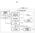
- FIG. 1 is a block diagram of a power storage system according to a first embodiment of the present invention.
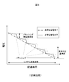
- FIG. 9 is a diagram illustrating a relationship between the voltage of the power storage element and the elapsed time when the power storage system is not operated constantly (when the power storage system is operated infrequently).
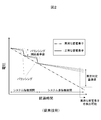
- FIG. 5 is a diagram illustrating a relationship between a voltage of a power storage element and an elapsed time when the power storage system is constantly operated.
- FIG. 7 is a diagram illustrating an accumulation result of balancing information of an accumulation calculation unit.
- FIG. 9 is a diagram illustrating a relationship between an accumulated balancing capacity value of an X-th power storage element and an abnormality determination reference value.
- FIG. 6 is a diagram illustrating a case where the same arithmetic processing as in FIG. 5 is performed and the X-th power storage element is not determined to be abnormal.
- FIG. 7 is a diagram illustrating a voltage transition of each storage element when the charge state is set to a high level.
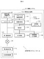
- FIG. 13 is a block diagram of a power storage system according to a fourth embodiment of the present invention. It is a block diagram of a power storage management system according to a fifth embodiment of the present invention.
- FIG. 1 is a block diagram of a power storage system according to the first embodiment of the present invention.
- a power storage system 1 ⁇ / b> A includes a power storage device 10 configured by connecting n (two or more) power storage elements 10 a, b,... N in series, and an abnormality detection device that detects abnormality of the power storage device 10. 100 and a controller 105 that controls the operation of the power storage device 10.
- the power storage device 10 includes at least one of a charging function and a discharging function of each power storage element in order to reduce a difference in a state of charge between the power storage elements.
- a charging function and a discharging function of each power storage element in order to reduce a difference in a state of charge between the power storage elements.
- the operation of reducing the difference in the state of charge between the storage elements that is, the operation of equalizing the state of charge between the storage elements, is simply referred to as a balancing operation.
- the abnormality detection device 100 includes a processor 100A and a storage unit 103 (storage) connected to the processor 100A.
- the processor 100A includes a balancing information acquisition unit 101, an accumulation calculation unit 102, and a determination unit 104, and the units 101, 102, and 104 are connected.
- the processor 100A reads out various types of information stored in the storage unit 103 and executes various processes described below.
- the processor 100A includes hardware including a CPU, a ROM, a RAM, and the like, and software, but may include a circuit.
- the storage unit 103 is configured by a storage medium such as a ROM, a RAM, and a nonvolatile memory.
- the balancing information acquisition unit 101 collects information relating to the balancing operation as information of the power storage device 10.
- Information related to the balancing operation includes a balancing operation time, the number of times of the balancing operation, a charge or discharge current value of each storage element during the balancing operation, and a charge or discharge of each storage element during the balancing operation. Including at least one of the electric capacity.
- the charging or discharging of each storage element during the balancing operation refers to charging or discharging that can be set for each storage element in order to equalize the state of charge between the storage elements connected in series. It is different from charging or discharging common to all the elements.
- the balancing information of the power storage device 10 acquired by the balancing information acquisition unit 101 is transmitted to the accumulation calculation unit 102, the storage unit 103, and the determination unit 104.
- the cumulative calculation unit 102 cumulatively calculates information on a plurality of balancing operations based on the balancing information of the power storage device 10 acquired by the balancing information acquiring unit 101.
- the storage unit 103 stores at least one of the balancing information accumulation results output from the balancing information acquisition unit 101 and the accumulation calculation unit 102. Of course, the storage unit 103 may store both.
- the storage unit 103 can also store an abnormality determination reference value used by the determination unit 104 for determining an abnormality of the storage element.
- FIG. 1 shows a configuration in which the accumulation result of accumulation calculation section 102 is stored in storage section 103, the balancing information of power storage device 10 acquired by balancing information acquisition section 101 is stored in storage section 103, and this balancing is performed. The information may be used for the calculation of the accumulation calculator 102.
- the storage unit 103 stores the first balancing information acquired by the balancing information acquiring unit 101, and the accumulation calculating unit 102 reads out the first balancing information stored in the storage unit 103, and reads the balancing information acquired by the balancing information acquiring unit.
- the configuration may be such that the second and subsequent balancing information acquired by 101 is directly input and cumulatively calculated. Further, every time the balancing information acquisition unit 101 acquires the balancing information, the storage unit 103 stores all the balancing information, and the accumulation calculation unit 102 reads out the balancing information stored a plurality of times in the storage unit 103 to read out the balancing information.
- a configuration for performing cumulative calculation may be used.
- the determination unit 104 uses the accumulation result of the balancing information output from the accumulation calculation unit 102 and the abnormality determination reference value stored in the storage unit 103 to store a plurality of power storage elements 10a, b,. It is determined whether or not any of the power storage elements indicates an abnormality in the rate of decrease in the state of charge.
- the abnormality determination result by the determination unit 104 is transmitted to the controller 105 and is reflected in the control of the power storage device 10. Further, the result of the determination as to whether or not the power storage device 10 is abnormal output from the determination unit 104 is input to an output device 106 including, for example, a monitor and a speaker, and transmitted to the user via the output device 106.
- FIG. 2 is a diagram illustrating a relationship between the voltage of the power storage element and the elapsed time when the power storage system is not operated at all times (operated at a low frequency).
- the horizontal axis indicates elapsed time
- the vertical axis indicates voltage
- the dashed-dotted line indicates data of an abnormal storage element
- the solid line indicates data of a normal storage element.
- the voltage of the abnormal power storage element decreases linearly with the passage of time, and the state of charge decreases rapidly.
- the balancing operation is performed every time the voltage difference between the power storage elements exceeds the reference value for starting the balancing operation, so that the voltage difference between the power storage elements does not spread to the abnormality determination reference value. It is not detected even if there is a large storage element.
- the non-operating period of the power storage system the balancing operation is not performed during this period
- the voltage difference between the power storage elements in the power storage system increases. As a result, if the operation of the power storage system is infrequent, an abnormal power storage element can be detected even in the related art.
- FIG. 3 is a diagram showing the relationship between the voltage of the storage element and the elapsed time when the power storage system is constantly operated.
- the voltage difference between the power storage elements in the power storage system does not exceed the abnormality determination reference value.
- an abnormal storage element is not detected in the related art.
- the voltage difference in the power storage system does not increase, the voltage difference between the normal power storage element and the abnormal power storage element is small. And the accuracy of the abnormality determination may be reduced.
- the power storage system is charged and discharged during operation, the state of charge changes.
- the magnitude relationship of the state of charge changes with charging and discharging the voltage difference between the abnormal storage element and the normal storage element may decrease, and the voltage at one point In the abnormality determination using only the difference, the abnormality determination itself may not be performed with high accuracy.
- FIG. 4 is a diagram illustrating a result of accumulation of balancing information by the accumulation calculation unit 102 in the present embodiment.
- FIG. 3 shows an example in which the balancing operation is performed by discharging.
- the horizontal axis indicates that the power storage device 10 includes n power storage elements, and the vertical axis indicates the value obtained by accumulating the balancing capacity (electric capacity) obtained by multiplying the balancing operation time by the discharge current of each power storage element.
- the result of the accumulation of the balancing capacity is shown in this figure, other than this, the accumulation of the balancing operation time and the accumulation of the number of times of the balancing operation can be used for determining an abnormal power storage element.
- a balancing operation (discharging) is not performed on a storage element having an abnormality in the state of charge decreasing speed, and a balancing operation (discharging) is performed on a normal group of storage elements. For this reason, the storage element having the abnormality in the rate of decrease in the state of charge has a smaller balancing capacity accumulation value as the X-th storage element in FIG. Based on this, the determination unit 104 determines from the accumulated value of the balancing information that the X-th power storage element is abnormal.
- FIG. 5 is a diagram illustrating a relationship between the balancing capacity accumulated value of the X-th power storage element and the abnormality determination reference value.
- the determination unit 104 calculates the average value of the accumulated values of the other storage elements without using the information of the storage element (X) having the smallest accumulated value, and calculates the average value of the accumulated values of the other storage elements.
- An abnormality can be determined when the difference between the accumulated value and the average value of the elements is larger than the abnormality determination reference value stored in the storage unit 103.
- the abnormality determination may be performed using the difference between the maximum value or the minimum value of the accumulated values of the storage elements other than the X-th storage element and the accumulated value of the X-th storage element.
- a known technique can be used for the determination, and the median value of the accumulated values of all the storage elements is used, or the average of the accumulated values of all the storage elements including the storage element (X) having the smallest accumulated value is used. Is also good.
- the abnormality of the power storage element is determined using the accumulated value of the balancing capacity (accumulated result), which is an example of the balancing information, so that the power storage system 1A does not depend on the operating state. , N, it is possible to determine that the rate of decrease in the state of charge of the X-th storage element is abnormal from among the plurality of storage elements a, b,.
- the period during which the cumulative calculation is performed can be arbitrarily set as long as the period is common to all power storage elements included in power storage device 10.
- the start time and end time of this period can be arbitrarily set.
- the difference in the charge state affects the balancing capacity.
- the state of charge at the end time is substantially the same.
- the amount of charged electricity and the amount of discharged electricity are distinguished and integrated, and a power storage element having a large amount of charged electricity or a small amount of discharged electricity can be determined to be abnormal.
- FIG. 6 is a block diagram illustrating an overall configuration of a power storage management system 110-1 according to the second embodiment of the present invention.
- the power storage system 1B includes a first communication device 107 in addition to the configuration of the power storage system 1A illustrated in FIG.
- the external management device 112 is connected to the second communication device 111, and is configured to transmit and receive information between the first communication device 107 and the second communication device 111 via the communication line 40. I have.
- the abnormality determination result by the determination unit 104 is transmitted from the first communication device 107 to the second communication device 111.
- the external management device 112 is composed of a server or the like capable of executing data accumulation and various types of arithmetic processing, and acquires and accumulates an abnormality determination result via the second communication device 111.
- the abnormality determination result is output to the output device 106 such as a monitor so that the administrator of the power storage system 1B, an operator who performs maintenance, and the like can know the abnormality determination result.
- the abnormality determination result can be separately notified from the first communication device 107 to a predetermined terminal such as an administrator via the communication line 40.
- the communication line 40 may be wireless or wired.
- the external management device 112 may receive and accumulate the balancing information output from the balancing information acquisition unit 101, the accumulation calculation unit 102, and the storage unit 103 as well as the result of the abnormality determination by the determination unit 104.
- one of the abnormality detection device 100 and the external management device 112 performs cumulative calculation of balancing information, and the other calculates the reduction rate of the state of charge of each of the storage elements a, b,... N based on the cumulative result of the balancing information.
- a configuration may be adopted in which an abnormality is determined and output.
- the functions of the accumulation calculation unit 102, the storage unit 103, and the determination unit 104 may be implemented remotely.
- each of the plurality of power storage systems does not require the functions of the accumulation calculation unit 102, the storage unit 103, and the determination unit 104, and a simple power storage management system can be constructed as a whole.
- the output results of the accumulation calculation unit 102, the storage unit 103, and the determination unit 104 executed by the external management device 112 may be displayed on the external management device 112 and utilized, or the second communication device 111 Communication may be performed with the power storage system 1B via the first communication device 107.
- a plurality of power storage elements are determined regardless of the operation state of the power storage system 1B by performing abnormality determination of the power storage element using the accumulated value of the balancing capacity, which is an example of balancing information. It is possible to determine that the rate of decrease in the state of charge of the X-th power storage element is abnormal among a, b,... n. Further, since various data can be transmitted and received between the power storage system 1B and the external management device 112, the management of the power storage system 1B is easy.
- hybrid hydraulic shovel (hybrid construction machine) equipped with the above-described power storage systems 1A and 1B is exemplified.
- a hybrid excavator according to a third embodiment will be described with reference to the drawings.
- the present invention can be applied to various types of hybrid construction machines, such as a hybrid wheel loader and a hybrid dump truck, that use the power of a hydraulic pump driven by an electric motor connected to a power storage device and an engine as a power source.
- the present invention is applied to various electric construction machines using a power storage device as a power source, and further to various machines having the same device configuration, that is, trains, hybrid electric vehicles, plug-in hybrid electric vehicles, electric vehicles, and the like. It is possible.
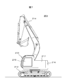
- FIG. 7 is a configuration diagram of a hybrid excavator 201 (hereinafter, referred to as a hybrid excavator 201) according to a third embodiment of the present invention.
- the hybrid shovel 201 is mounted on a traveling body 212, a revolving body 213 rotatably provided on the traveling body 212, and one side (right side when facing forward) of a front portion of the revolving body 213, and is mounted in a vertical direction.
- a front work machine 214 that rotates and performs work such as excavation.
- the traveling body 212, the revolving superstructure 213, and the front work machine 214 all correspond to the "hydraulic load" of the present invention.
- the revolving superstructure 213 includes a cabin 215 disposed on the other side of the front part (left side when facing front), a counter weight 216 disposed on the rear part, and a weight balance of the vehicle body, a cabin 215 and a counter weight 216. And a motor room 217 in which an engine 221 described later is stored.
- FIG. 8 is a functional block diagram of a hybrid shovel 201 according to the third embodiment.
- the revolving superstructure 213 is provided in the engine 221, a fuel tank (not shown) for storing fuel of the engine 221, a governor (not shown) for adjusting a fuel injection amount of the engine 221, and the engine 221.
- a turbocharger type supercharger (not shown) and an engine controller (engine control unit: ECU) 222 for controlling the operation of the engine 221 are provided.
- ECU engine control unit
- the revolving superstructure 213 is connected to the engine 221 and is disposed on an auxiliary load 223 such as an air conditioner operated by the driving force of the engine 221 and an auxiliary load on the driving shaft of the engine 221 to transmit torque between the engine 221 and the engine 221.
- a motor generator (motor generator: M / G) 224 for assisting and generating power of the engine 221, an inverter 225 connected to the motor generator 224 and controlling the operation of the motor generator 224
- a power storage device 226 that exchanges power with the motor generator 224 via the motor 225 is connected in series to the engine 221 and the motor generator 224, and operates with the driving force of the engine 221 and the motor generator 224.
- a variable displacement hydraulic pump hereinafter referred to as a hydraulic pump for convenience
- a pilot pump for generating a pilot pressure oil (not shown) by operating the driving force of the down 221.
- the motor generator 224 assists the power of the engine 221 during power running, drives the auxiliary load 223 and the hydraulic pump 227 connected to the engine 221, and generates power during regeneration.
- the inverter 225 converts DC power into AC power, and converts AC power into DC power.
- the power storage device 226 is connected, for example, to a battery cell group 226A formed by connecting a plurality of lithium ion batteries (power storage elements) in series, and connected between the battery cell group 226A and the inverter 225 to form a battery cell group 226A.
- a battery controller (battery control unit: BCU) 226C connected to the battery cell group 226A and the current sensor 226B for measuring and managing the voltage, temperature, current, etc. of the battery cell group 226A. ,have.
- the revolving superstructure 213 is connected to a control valve 220 for controlling the flow (flow rate and direction) of the pressure oil, an engine controller 222, an inverter 225, and a battery controller 226C, and includes a body including operations of the hydraulic pump 227 and the inverter 225. And a hybrid controller (Hybrid Control Unit: HCU) 229 as a control device for controlling the entire operation.
- a hybrid controller Hybrid Control Unit: HCU
- the battery controller 226C converts the measured value of the current sensor 226B into an analog signal, inputs the converted value as a current, and measures each cell voltage and each cell temperature of the battery cell group 226A. Based on these currents, each cell voltage and each cell temperature, calculation of the state of charge of the battery cell group 226A, calculation of the maximum power that can be charged and discharged, and operation of balancing the state of charge are performed. Then, these cell voltage, cell temperature, current, SOC (State of charge), allowable charge / discharge power, and balancing signal are transmitted to hybrid controller 229.
- the abnormality detection device 100 acquires the above various information and uses it for abnormality detection.
- abnormality detection device 100 is shown in FIG. 8 independently of the battery controller 226C and the hybrid controller 229, the same function may be built in the battery controller 226C and the hybrid controller 229.
- the charging / discharging method and the operation rate are greatly different for each vehicle body depending on circumstances such as an operator and construction.
- the number of components tends to increase as compared with the case where the power storage system is used alone as in the first and second embodiments, and the frequency and period of maintenance may increase.
- the output device 106 when it is determined that the storage element is abnormal, notifies the operator or maintenance worker of the determined abnormality. You. This notification is made by using a display on the monitor (notification device) 215A of the hybrid shovel 201 or using communication means such as an e-mail or telephone via the communication terminal 230 as shown in FIG. Leaving a power storage system including an abnormal power storage element for a long period of time may cause a trouble during operation. Therefore, it is preferable that an operator or a maintenance person who has received the notification immediately perform the balancing operation. Further, it is preferable to change the operation so that the non-operation period of the hybrid shovel 201 that has issued the notification does not continue in the operation plan.
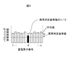
- FIG. 9 is a diagram illustrating a case where the same arithmetic processing as in FIG. 5 is performed and the X-th power storage element is not determined to be abnormal.
- the balancing operation is performed by discharging, and the vertical axis is the balancing capacity accumulated value.
- determination section 104 can estimate that after the period 2T has elapsed, the difference between the cumulative value of the X-th power storage element and the average value of the cumulative values of the other power storage elements reaches the abnormality determination reference value. it can.
- the estimation result is notified to the user via the output device 106 and / or notified to the outside via the first communication device 107 (see FIGS. 1 and 6). At this time, it is preferable that the time when the non-operation period 2T of the hybrid shovel 201 elapses is reflected in the maintenance plan as the abnormality occurrence time.
- the voltage difference between the abnormal power storage element and the normal power storage element expands to a predetermined value or more by restarting the operation before the time 2T elapses, or performing only the balancing operation before the time 2T elapses.
- This can be prevented beforehand, and a situation in which the hybrid shovel 201 cannot be operated due to an unexpected trouble (such as generation of a maintenance alarm of the power storage device 10) can be prevented.
- the abnormality occurrence time of each power storage element is estimated from the cumulative period of the balancing capacity, which is an example of the balancing information, the cumulative value of the balancing capacity, and the abnormality determination reference value. Therefore, the planned operation and maintenance of the hybrid shovel 201 can be planned with reference to the estimated abnormality occurrence time. In addition, by performing a balancing operation or performing maintenance or the like before the abnormality occurrence time comes, an abnormal state of the power storage element can be prevented.
- the non-operation period is, for example, 3T in the operation plan of the hybrid shovel 201.
- the charging state of the X-th power storage element is set in advance to be higher than the other power storage elements, thereby extending the period until the occurrence of the abnormality and preventing occurrence of unexpected trouble. be able to.
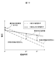
- FIG. 10 is a diagram showing a voltage transition of each storage element when the charge state is set to a high level.
- FIG. 10 shows a state in which the voltage of the X-th power storage element is set to be higher by half of the abnormality determination reference value at the time point of elapsed time 0.
- Such a state can be realized by various means, but can be realized by discharging a normal power storage element during the balancing operation. For example, at the time point of elapsed time 0, the storage elements other than the X-th element are discharged by an amount of electricity corresponding to half of the abnormality determination reference value, and then all the storage elements are charged by an amount of electricity corresponding to half of the abnormality determination reference value. By doing so, the situation of FIG. 10 can be realized.
- FIG. 11 is a block diagram of a power storage system 1C according to the fourth embodiment of the present invention.
- the abnormality detection device 100 calculates a time when the balancing operation of the power storage device 10 is necessary (for example, when the non-operation period 2T, which is the time when the abnormality occurs, / see FIG. 10).
- the operator inputs the next operation time of the hybrid shovel 201 from the operation information input unit 108.
- the next operation day may be input, or a period during which the hybrid shovel 201 does not operate (for example, 3T) may be input.
- the abnormality detection device 100 outputs a command to the controller 105 to discharge the power storage elements other than the Xth by an amount of electricity corresponding to half of the abnormality determination reference value. , Only the X-th power storage element is higher by half the voltage of the abnormality determination reference value, that is, the state at the elapsed time 0 in FIG. 10 can be realized.
- the voltage of the X-th power storage element is set higher by a voltage corresponding to half of the abnormality determination reference value regarding the amount of discharged electricity.
- the time when the abnormality occurs can be delayed by a time corresponding to the difference between 3T and 2T.
- the cycle of the balancing operation and the maintenance cycle can be extended, and the operation efficiency of the hybrid shovel 201 improves.
- a method for discharging the storage elements other than the X-th storage element is disclosed in order to set the charge state of the X-th storage element to be higher.
- a mechanism for charging higher by half the voltage may be provided.
- the power storage element that sets a higher charging state is shown. It is also possible to set a higher charge state for the element.
- FIG. 12 is a block diagram of a power storage management system 110-2 according to the fifth embodiment of the present invention.
- the power storage system 1D illustrated in FIG. 12 has a configuration in which the first communication device 107 is added to the power storage system 1C illustrated in FIG. 11 and is mounted on the hybrid shovel 201.
- the external management device 112 is connected to the second communication device 111, and is output from the abnormality detection device 100 including the operation information of the hybrid shovel 201 via the first communication device 107 and the second communication device 111. Information can be stored in the external management device 112.
- the power storage elements a, b,... N are independent of the operation state of the power storage system 1D. It can be determined that the rate of decrease in the state of charge of the X-th power storage element is abnormal. Further, since various data including the operation information of the hybrid shovel 201 can be transmitted and received between the power storage system 1D and the external management device 112, the management of the power storage system 1D is easy.
- the configuration in which the operation information input unit 108 is provided in the hybrid shovel 201 is disclosed.
- the operation information input unit 108 may be provided in the external management device 112. This is convenient when the work site of the hybrid shovel 201 is far from the management room where the external management device 112 is installed.
- the present invention is not limited to the above-described first to fifth embodiments, but includes various modifications.
- the above-described first to fifth embodiments have been described in detail for easy understanding of the present invention, and are not necessarily limited to those having all the described configurations.
- the main configuration of the present invention is that an abnormality in the rate of decrease in the state of charge is determined using the result of accumulating balancing information a plurality of times. With this configuration, the accuracy of the determination is not affected as in the case where the abnormality in the rate of decrease in the state of charge is determined from the balancing information for each time based on the voltage measurement accuracy or the like, and the operation rate of the power storage system is high and balancing is frequently performed. In this case, the above-described abnormality can be determined even when the charging state and the voltage do not vary.
- control lines and the information lines are considered to be necessary for the description, and do not necessarily indicate all the control lines and the information lines on the product. In fact, it may be considered that almost all components are interconnected.
- 1A to 1D power storage system
- 10 power storage device
- 10a to n power storage element
- 100 abnormality detection device
- 101 balancing information acquisition unit
- 102 cumulative calculation unit
- 103 storage unit (storage)
- 104 determination unit
- 105 controller
- 106 output device
- 107 first communication device
- 108 operation information input device
- 110-1, 110-2 power storage management system
- 111 second communication device
- 112 external management device
- 212 ... traveling body (hydraulic load), 213... revolving body (hydraulic load), 214... front work machine (hydraulic load), 215 A... monitor (notification device)
- 221... engine 224 motor generator (M / G)
- 225 inverter
- 226 power storage device
- 226A battery cell group (power storage element)
- 226C Battery controller
- 227 ... hydraulic pump 229 ... hybrid controller (HCU)
Landscapes
- Engineering & Computer Science (AREA)
- Chemical & Material Sciences (AREA)
- Mechanical Engineering (AREA)
- Transportation (AREA)
- Power Engineering (AREA)
- Manufacturing & Machinery (AREA)
- Chemical Kinetics & Catalysis (AREA)
- Electrochemistry (AREA)
- General Chemical & Material Sciences (AREA)
- Sustainable Energy (AREA)
- Life Sciences & Earth Sciences (AREA)
- Combustion & Propulsion (AREA)
- Sustainable Development (AREA)
- General Physics & Mathematics (AREA)
- Civil Engineering (AREA)
- Mining & Mineral Resources (AREA)
- General Engineering & Computer Science (AREA)
- Physics & Mathematics (AREA)
- Structural Engineering (AREA)
- Automation & Control Theory (AREA)
- Charge And Discharge Circuits For Batteries Or The Like (AREA)
- Secondary Cells (AREA)
- Electric Propulsion And Braking For Vehicles (AREA)
Abstract
蓄電システムの稼働状態に依存せず、充電状態の低下速度に異常のある蓄電素子を検出すること。 蓄電装置(10)と、蓄電素子(10a,b)間の充電状態の差を均等化するバランシング動作を制御するコントローラ(105)と、蓄電装置の異常を検出する異常検出装置(100)と、を備えた蓄電システムにおいて、異常検出装置(100)は、コントローラ(105)によるバランシング動作の複数回の履歴情報を累積計算し、バランシング動作の履歴情報の累積結果に基づき、各蓄電素子の充電状態の低下速度の異常を判定し、当該判定の結果を出力する。
Description
本発明は、蓄電装置の異常を検出する蓄電システムと、その蓄電システムを管理する蓄電管理システムに関し、例えばハイブリッド式建設機械などの技術分野に好適なものである。
近年、建設機械等の移動体に搭載された動力源を電動化する取り組みがなされている。動力源の電動化は、電力を蓄える蓄電装置を電源とし、移動体に搭載された電動モータを、蓄電装置から供給された電力によって駆動することにより実現できる。
蓄電装置は、リチウムイオン電池、鉛電池、NAS電池、レドックスフロー電池等の二次電池や、電気二重層キャパシタ、リチウムイオンキャパシタ等のキャパシタといった蓄電素子を用いて構成され、最近では、二次電池の中でも、入出力およびエネルギー密度が高いリチウムイオン電池の採用が増加している。また、大容量化を図るために、蓄電装置は、複数の蓄電素子が直列および/または並列に接続されて構成される。そして、蓄電装置とコントローラ等の制御装置とを組み合わせることにより、蓄電システムが構成される。長期に渡って蓄電システムを安全に使用し続けるためには、コントローラが各蓄電素子の電圧、充放電電流、充電状態等を監視し、各蓄電素子が適正な使用範囲内で使用されるように制御する必要がある。
ここで、直列接続された蓄電素子間の充電状態の差を低減するために、各蓄電素子の充電状態を調整し、均等化するバランシング技術が知られている。特許文献1には、複数の蓄電素子の情報に基づいて、蓄電素子間の充電状態を均等化(バランシング)するように、充電状態の高い蓄電素子を選択して放電する構成が開示されている。
また、バランシング制御情報を用いて蓄電装置の異常を判定する方法が開示されている。特許文献2には、自然放電による電力減少量を積算し補正する補正部を備えた構成において、補正量が適正範囲以内であるか否かを判定することで電池モジュール自体の異常を判定する技術が開示されている。さらに特許文献3には、複数の蓄電素子の充電状態のばらつきから、充電状態を調整する予測時間を演算し、実際の調整に要した実測時間を用いて異常の種類を判定する技術が開示されている。
各蓄電素子の充電状態を均等化するためには、充電状態の低下速度に異常のある蓄電素子を判定する必要がある。しかしながら、特許文献2のように電圧に基づいて取得される充電率の補正量の差の大きさに基づく判定方法や、特許文献3のように電圧差に基づくバランシング時間の予測と実測を比較する判定方法では、蓄電素子間に充電状態のばらつきが生じていることが必要となるため、充電状態のばらつきが生じないようにバランシングが定常的に実施されている使用環境下では、蓄電素子の充電状態の低下速度に異常があるか否かを検出することが困難であった。
本発明は、上述した従来技術の問題に鑑みなされたもので、本発明の目的は、蓄電システムの稼働状態に依存せず、充電状態の低下速度に異常のある蓄電素子を検出することにある。
上記課題を解決するため、本発明の一態様は、複数の蓄電素子を直列接続して構成された蓄電装置と、直列接続された前記蓄電素子間の充電状態の差を均等化する動作であるバランシング動作を制御するコントローラと、前記蓄電装置の異常を検出する異常検出装置と、を備えた蓄電システムにおいて、前記異常検出装置は、前記コントローラによる前記バランシング動作の複数回の履歴情報を累積計算し、前記バランシング動作の履歴情報の累積結果に基づき、前記各蓄電素子の充電状態の低下速度の異常を判定し、当該判定の結果を出力することを特徴とする。
本発明によれば、蓄電システムの稼働状態に依存せず、充電状態の低下速度に異常がある蓄電素子を検出できる。なお、上記した以外の課題、構成及び効果は、以下の実施形態の説明により明らかにされる。
以下、本発明の各実施形態について図面を参照して説明する。なお、各図において同一要素については同一の符号を付し、重複する説明は省略する。
(第1の実施形態)
第1の実施形態では、例えば、再生可能エネルギーを利用した発電所や電力需要家に、本発明に係る蓄電システムが単独で設置される場合について説明する。図1は、本発明の第1の実施形態に係る蓄電システムのブロック図である。図1において、蓄電システム1Aは、n(2以上の数)個の蓄電素子10a,b,…nを直列接続して構成された蓄電装置10と、蓄電装置10の異常を検出する異常検出装置100と、蓄電装置10の動作を制御するコントローラ105と、を含む。
第1の実施形態では、例えば、再生可能エネルギーを利用した発電所や電力需要家に、本発明に係る蓄電システムが単独で設置される場合について説明する。図1は、本発明の第1の実施形態に係る蓄電システムのブロック図である。図1において、蓄電システム1Aは、n(2以上の数)個の蓄電素子10a,b,…nを直列接続して構成された蓄電装置10と、蓄電装置10の異常を検出する異常検出装置100と、蓄電装置10の動作を制御するコントローラ105と、を含む。
ここで蓄電装置10は、蓄電素子間の充電状態の差を低減するために各蓄電素子の充電または放電機能の少なくとも一方を備えている。以下、蓄電素子間の充電状態の差を低減する動作、すなわち、蓄電素子間の充電状態を均等化する動作を単にバランシング動作と記載する。
異常検出装置100は、プロセッサ100Aと、これに接続された記憶部103(ストレージ)とを有する。プロセッサ100Aは、バランシング情報取得部101と、累積計算部102と、判定部104と、を備えており、各部101、102、104は接続されている。プロセッサ100Aは、記憶部103に記憶されている各種情報を読み出して、後述する各種処理を実行する。なお、プロセッサ100Aは、CPU、ROM、RAM等を含むハードウェアと、ソフトウェアとを備えて構成されているが、サーキットで構成されていても良い。また、記憶部103は、ROM、RAM、不揮発性メモリなどの記憶媒体等により構成されている。
バランシング情報取得部101は、蓄電装置10の情報として、バランシング動作に関連する情報を収集する。バランシング動作に関連する情報(以下、バランシング情報)は、バランシング動作時間、バランシング動作回数、バランシング動作中の各蓄電素子の充電または放電の電流値や、バランシング動作中の各蓄電素子の充電または放電の電気容量の少なくとも一つを含む。なお、バランシング動作中の各蓄電素子の充電または放電とは、直列接続された蓄電素子間の充電状態を均等化するために蓄電素子ごとに設定可能な充電または放電を示し、直列接続された蓄電素子すべてに共通する充電または放電とは異なる。バランシング情報取得部101で取得した蓄電装置10のバランシング情報は、累積計算部102や記憶部103、判定部104に送信される。
累積計算部102は、バランシング情報取得部101で取得した蓄電装置10のバランシング情報に基づいて、複数回のバランシング動作の情報を累積計算する。
記憶部103は、バランシング情報取得部101および累積計算部102から出力されるバランシング情報の累積結果の少なくとも一方を記憶する。勿論、記憶部103は両方を記憶しても良い。記憶部103は、判定部104が蓄電素子の異常判定に用いるための異常判定基準値を記憶することもできる。なお、図1では、累積計算部102の累積結果を記憶部103に記憶する構成を示したが、バランシング情報取得部101で取得した蓄電装置10のバランシング情報を記憶部103に記憶し、このバランシング情報を累積計算部102の計算に用いても良い。すなわち、バランシング情報取得部101が取得した1回目のバランシング情報を記憶部103が記憶し、累積計算部102は、記憶部103に記憶されている1回目のバランシング情報を読み出すと共に、バランシング情報取得部101が取得した2回目以降のバランシング情報を直接入力して累積計算する構成とすることができる。また、バランシング情報取得部101がバランシング情報を取得する毎に、記憶部103がそのバランシング情報を全て記憶し、累積計算部102は、記憶部103に記憶されている複数回のバランシング情報を読み出して累積計算する構成であっても良い。
判定部104は、累積計算部102から出力されるバランシング情報の累積結果や、記憶部103に記憶された異常判定基準値を用いて、蓄電装置10を構成する複数の蓄電素子10a,b…nの中に充電状態の低下速度の異常を示す蓄電素子が含まれるか否かを判定する。判定部104による異常判定結果は、コントローラ105に伝達され、蓄電装置10の制御に反映される。また、判定部104から出力される蓄電装置10の異常の有無の判定結果は、例えばモニタやスピーカ等から成る出力装置106に入力され、出力装置106を介してユーザに伝達される。
(蓄電素子の充電状態低下速度の異常判定方法)
図2は、蓄電システムを常時稼働させない場合(低頻度で稼働させた場合)の蓄電素子の電圧と経過時間との関係を示す図である。図2の横軸は経過時間、縦軸は電圧を示し、一点鎖線は異常な蓄電素子のデータ、実線は正常な蓄電素子のデータを示している。異常な蓄電素子(一点鎖線)は、時間の経過とともに直線的に電圧が低下しており、充電状態低下速度が速い。一方、正常な蓄電素子(実線)では、バランシング動作時以外の電圧低下は緩やかだが、蓄電システム内の電圧差がバランシング動作の開始基準値を超えた場合に、電圧の高い蓄電素子を放電するバランシング動作によって、最も電圧が低い蓄電素子(異常な蓄電素子)に合わせる形で電圧が均一化されている。
図2は、蓄電システムを常時稼働させない場合(低頻度で稼働させた場合)の蓄電素子の電圧と経過時間との関係を示す図である。図2の横軸は経過時間、縦軸は電圧を示し、一点鎖線は異常な蓄電素子のデータ、実線は正常な蓄電素子のデータを示している。異常な蓄電素子(一点鎖線)は、時間の経過とともに直線的に電圧が低下しており、充電状態低下速度が速い。一方、正常な蓄電素子(実線)では、バランシング動作時以外の電圧低下は緩やかだが、蓄電システム内の電圧差がバランシング動作の開始基準値を超えた場合に、電圧の高い蓄電素子を放電するバランシング動作によって、最も電圧が低い蓄電素子(異常な蓄電素子)に合わせる形で電圧が均一化されている。
蓄電システムが稼働している間は、蓄電素子間の電圧差がバランシング動作の開始基準値を超える毎にバランシング動作が行われるため、蓄電素子間の電圧差が異常判定基準値まで広がらず、異常な蓄電素子が存在しても検出されない。しかし、蓄電システムの非稼働期間(この間はバランシング動作も実施されない)が一定以上の時間継続すると、蓄電システム内の蓄電素子間の電圧差が拡大する。その結果、蓄電システムの稼働が低頻度であれば、従来技術においても異常な蓄電素子を検出可能となる。
図3は、蓄電システムを常時稼働させた場合の蓄電素子の電圧と経過時間との関係を示す図である。図3の場合においては、バランシング動作が高頻度で実施された結果、蓄電システム内の蓄電素子間の電圧差が異常判定基準値を超えることがない。このような場合には、従来技術では異常な蓄電素子が検出されない。また、蓄電システム内の電圧差が拡大しないことから、正常な蓄電素子と異常な蓄電素子との電圧差が小さいため、電圧差を用いて判定する従来技術の手法では電圧測定誤差の影響が相対的に大きくなり、異常判定の精度が低下する虞がある。さらに、蓄電システムは稼働時に充放電されるため、充電状態が変化する。各蓄電素子の容量にばらつきが存在する場合、充放電に伴い充電状態の大小関係が変化し、異常な蓄電素子と正常な蓄電素子との電圧差が小さくなる場合もあり、一時点での電圧差のみを用いた異常判定では、異常判定自体を精度良く行えない虞があった。
このような従来技術の課題を解決するために、本実施形態では次に説明するような異常判定手法を用いる。図4は、本実施形態における累積計算部102のバランシング情報の累積結果を示す図である。なお、本図においては、バランシング動作が放電で実施されている例を示す。横軸は蓄電装置10内にn個の蓄電素子が含まれることを示し、縦軸はバランシング動作時間に各蓄電素子の放電電流を掛けたバランシング容量(電気容量)を累積した値を示す。本図ではバランシング容量の累積結果を示したが、これ以外にも、バランシング動作時間の累積、バランシング動作回数の累積を異常な蓄電素子の判定に用いることができる。
図3に示すように、充電状態低下速度の異常を有する蓄電素子はバランシング動作(放電)が実行されず、正常な蓄電素子群はバランシング動作(放電)が実行される。そのため、充電状態低下速度の異常を有する蓄電素子は図4のX番目の蓄電素子のように、バランシング容量累積値が小さくなる。このことに基づき、判定部104は、バランシング情報の累積値からX番目の蓄電素子が異常であることを判定する。
図5は、X番目の蓄電素子のバランシング容量累積値と異常判定基準値との関係を示す図である。図5に示すように、判定部104は、累積値が最小の蓄電素子(X)の情報を用いず、それ以外の蓄電素子の累積値の平均値を算出し、上記累積値が最小の蓄電素子の累積値と平均値との差が、記憶部103に記憶された異常判定基準値よりも大きい場合を異常と判定することができる。勿論、X番目以外の蓄電素子の累積値の最大値または最小値とX番目の蓄電素子の累積値との差を用いて異常判定を行っても良い。また、判定は公知の技術を使用可能であり、全蓄電素子の累積値の中央値を利用したり、累積値が最小の蓄電素子(X)を含む全蓄電素子の累積値の平均を用いても良い。
このように、第1の実施形態によれば、バランシング情報の一例であるバランシング容量の累積値(累積結果)を用いて蓄電素子の異常判定を行うことで、蓄電システム1Aの稼働状態に依らず、複数の蓄電素子a,b,…nの中からX番目の蓄電素子の充電状態の低下速度が異常であることを判定できる。
ここで、累積計算を行う期間は、蓄電装置10に含まれる全蓄電素子に対して共通であれば任意に設定可能である。この期間の開始時期および終了時期も同様に任意に設定可能であるが、各蓄電素子の充電容量のばらつきが存在する場合、充電状態の違いがバランシング容量に影響するため、この期間の開始時期および終了時期の充電状態が略同一であるのが好ましい。
また、本実施形態では、バランシング動作を放電で実施する場合について記載したため、図2および図3では正常な蓄電素子の電圧がバランシング動作中に低下し、図4および図5で異常な蓄電素子のバランシング容量累積値が正常な蓄電素子に比べて小さい値を示した。一方、バランシング動作を充電で実施する場合には、図2および図3では異常な蓄電素子の電圧がバランシング動作中に上昇し、図4および図5で累積されるデータは各蓄電素子の充電電気量となり、異常な蓄電素子のバランシング容量累積値が正常な蓄電素子に比べて高い値を示すこととなる。また、バランシング動作を充電および放電で実施する場合においても、充電電気量と放電電気量を区別して積算し、充電電気量が多いまたは放電電気量が少ない蓄電素子を異常と判定することができる。
(第2の実施形態)
次に、本発明の第2の実施形態について説明する。第2の実施形態では、蓄電システム1Bと外部管理装置112とを通信回線40を介して接続した蓄電管理システム110-1を例示する。図6は、本発明の第2の実施形態に係る蓄電管理システム110-1の全体構成を示すブロック図である。図6に示すように、蓄電システム1Bは、図1に示す蓄電システム1Aの構成に加えて、第1通信装置107を備える。また、外部管理装置112は、第2通信装置111と接続されており、第1通信装置107と第2通信装置111との間で通信回線40を介して情報の送受信が行われる構成となっている。
次に、本発明の第2の実施形態について説明する。第2の実施形態では、蓄電システム1Bと外部管理装置112とを通信回線40を介して接続した蓄電管理システム110-1を例示する。図6は、本発明の第2の実施形態に係る蓄電管理システム110-1の全体構成を示すブロック図である。図6に示すように、蓄電システム1Bは、図1に示す蓄電システム1Aの構成に加えて、第1通信装置107を備える。また、外部管理装置112は、第2通信装置111と接続されており、第1通信装置107と第2通信装置111との間で通信回線40を介して情報の送受信が行われる構成となっている。
より詳細に説明すると、図6に示す蓄電システム1Bでは、判定部104による異常判定結果が、第1通信装置107から第2通信装置111に送信される。外部管理装置112はデータの蓄積や各種演算処理を実行可能なサーバー等からなり、第2通信装置111を介して異常判定結果を取得して蓄積する。また、異常判定結果は、モニタ等の出力装置106に出力され、蓄電システム1Bの管理者や、メンテナンスを実行する作業者等が異常判定結果を知ることができる構成となっている。あるいは、第1通信装置107から別途、通信回線40を介して管理者等の所定の端末に異常判定結果を通知することもできる。なお、通信回線40は無線でも有線でも良い。
さらに、外部管理装置112は、判定部104による異常判定結果だけでなく、バランシング情報取得部101、累積計算部102、記憶部103から出力されるバランシング情報を受信し、蓄積しても良い。この場合、異常検出装置100と外部管理装置112とのうち一方がバランシング情報を累積計算し、他方がバランシング情報の累積結果に基づき、各蓄電素子a,b,…nの充電状態の低下速度の異常を判定して出力する構成とすることができる。また、バランシング情報取得部101から出力される情報のみを外部管理装置112で受信し、累積計算部102、記憶部103、判定部104の機能を遠隔で実施してもよい。このような構成では、複数の蓄電システムそれぞれが累積計算部102、記憶部103、判定部104の機能を必要とせず、全体として簡略な蓄電管理システムを構築できる。また、外部管理装置112で実行した、累積計算部102、記憶部103、判定部104の出力結果は外部管理装置112にて表示するなどして活用しても良いし、第2通信装置111および第1通信装置107を介して蓄電システム1Bへ通信されても良い。
上記した蓄電管理システム110-1によれば、バランシング情報の一例であるバランシング容量の累積値を用いて蓄電素子の異常判定を行うことで、蓄電システム1Bの稼働状態に依らず、複数の蓄電素子a,b,…nの中からX番目の蓄電素子の充電状態の低下速度が異常であることを判定できる。また、蓄電システム1Bと外部管理装置112との間で各種データを送受信できるため、蓄電システム1Bの管理が容易である。
(第3の実施形態)
第3の実施形態では、上記した蓄電システム1A,1Bを搭載したハイブリッド油圧ショベル(ハイブリッド式建設機械)を例示する。以下、第3の実施形態に係るハイブリッド油圧ショベルについて図面に従って説明する。なお、第3の実施形態では、リチウムイオン電池を搭載したハイブリッド油圧ショベルを例に挙げて説明するが、これに限るものではない。例えば、本発明は、ハイブリッドホイールローダ、ハイブリッドダンプトラック等、蓄電装置に接続された電動モータとエンジンとにより駆動される油圧ポンプの動力を動力源とした各種のハイブリッド建設機械に適用できる。また、蓄電装置を動力源とした各種の電動建設機械、さらには、同様の機器構成の各種の機械、すなわち、電車、ハイブリッド電気自動車、プラグインハイブリッド電気自動車、電気自動車等にも本発明は適用可能である。
第3の実施形態では、上記した蓄電システム1A,1Bを搭載したハイブリッド油圧ショベル(ハイブリッド式建設機械)を例示する。以下、第3の実施形態に係るハイブリッド油圧ショベルについて図面に従って説明する。なお、第3の実施形態では、リチウムイオン電池を搭載したハイブリッド油圧ショベルを例に挙げて説明するが、これに限るものではない。例えば、本発明は、ハイブリッドホイールローダ、ハイブリッドダンプトラック等、蓄電装置に接続された電動モータとエンジンとにより駆動される油圧ポンプの動力を動力源とした各種のハイブリッド建設機械に適用できる。また、蓄電装置を動力源とした各種の電動建設機械、さらには、同様の機器構成の各種の機械、すなわち、電車、ハイブリッド電気自動車、プラグインハイブリッド電気自動車、電気自動車等にも本発明は適用可能である。
図7は、本発明の第3の実施形態に係るハイブリッド油圧ショベル201(以下、ハイブリッドショベル201という)の構成図である。このハイブリッドショベル201は、走行体212と、この走行体212上に旋回可能に設けられた旋回体213と、旋回体213の前部の片側(前方を向いて右側)に取り付けられ、上下方向に回動して掘削等の作業を行うフロント作業機214とを備えている。なお、走行体212、旋回体213、フロント作業機214は、何れも本発明の「油圧負荷」に相当する。
旋回体213は、前部の他方の片側(前方を向いて左側)に配置されたキャビン215と、後部に配置され、車体の重量のバランスを保つカウンタウェイト216と、キャビン215とカウンタウェイト216との間に配置され、後述のエンジン221が収納される原動機室217とを備えている。
図8は、第3の実施形態に係るハイブリッドショベル201の機能ブロック図である。旋回体213は、前述のエンジン221と、エンジン221の燃料を貯蔵する燃料タンク(図示せず)と、エンジン221の燃料噴射量を調整するガバナ(図示せず)と、エンジン221に設けられたターボチャージャ式の過給機(図示せず)と、エンジン221の動作を制御するエンジンコントローラ(エンジンコントロールユニット:ECU)222とを備えている。
また、旋回体213は、エンジン221に接続され、エンジン221の駆動力で動作するエアコン等の補機負荷223と、エンジン221の駆動軸上に配置され、エンジン221との間でトルクを伝達することにより、エンジン221の動力のアシストおよび発電を行う電動発電機(モータジェネレータ:M/G)224と、この電動発電機224に接続され、電動発電機224の動作を制御するインバータ225と、インバータ225を介して電動発電機224との間で電力の授受を行う蓄電装置226と、エンジン221および電動発電機224に対して直列に接続され、エンジン221および電動発電機224の駆動力で動作することにより圧油を吐出する可変容量型油圧ポンプ(以下、便宜的に油圧ポンプと呼ぶ)227と、エンジン221の駆動力で動作することによりパイロット圧油を生成するパイロットポンプ(図示せず)とを備えている。
電動発電機224は、力行時にエンジン221の動力をアシストし、エンジン221に接続された補機負荷223および油圧ポンプ227を駆動するとともに、回生時に発電を行う。インバータ225は、直流電力を交流電力に変換し、交流電力を直流電力に変換するものである。蓄電装置226は、例えば、リチウムイオン電池(蓄電素子)を複数個直列に接続して形成された電池セル群226Aと、この電池セル群226Aとインバータ225との間に接続され、電池セル群226Aの電流を測定する電流センサ226Bと、電池セル群226Aおよび電流センサ226Bに接続され、電池セル群226Aの電圧、温度、電流等を測定して管理するバッテリコントローラ(バッテリコントロールユニット:BCU)226Cと、を有している。
また、旋回体213は、圧油の流れ(流量および方向)を制御するコントロールバルブ220と、エンジンコントローラ222、インバータ225、およびバッテリコントローラ226Cに接続され、油圧ポンプ227およびインバータ225の動作を含む車体全体の動作を制御する制御装置としてのハイブリッドコントローラ(ハイブリッドコントロールユニット:HCU)229とを備えている。
バッテリコントローラ226Cは、電流センサ226Bの測定値をAD変換し、電流として入力するとともに、電池セル群226Aの各セル電圧および各セル温度を測定する。これらの電流、各セル電圧および各セル温度に基づいて、電池セル群226Aの充電状態の演算、充放電可能な最大電力の演算、および充電状態のバランシング動作を実施する。そして、これらのセル電圧、セル温度、電流、SOC(State of charge)、許容充放電電力、およびバランシング信号をハイブリッドコントローラ229に送信する。異常検出装置100は、上記各種情報を取得し、異常検出に用いる。
なお、図8において異常検出装置100をバッテリコントローラ226Cおよびハイブリッドコントローラ229と独立して示したが、同様の機能がバッテリコントローラ226Cおよびハイブリッドコントローラ229に内蔵されていても良い。
このような構成において、ハイブリッドショベル201で使用される蓄電システムは、オペレータおよび工事等の事情により充放電方法や稼働率が車体ごとに大きく異なる。また、第1および第2の実施形態のように蓄電システム単独で用いられる場合と比較して部品点数が多くなる傾向があり、メンテナンスの頻度や期間が長くなる場合がある。
このような事情を踏まえて、第3の実施形態においては、蓄電素子の異常を判定した場合には、出力装置106(図1,6参照)からオペレータやメンテナンス員に判定された異常が通知される。この通知は、図8に示すようにハイブリッドショベル201のモニタ(報知装置)215Aへの表示や、通信端末230を経由した電子メールや電話等の通信手段を用いてなされる。異常な蓄電素子を含む蓄電システムを長期間放置することは、稼働時にトラブル発生の原因に成り得るため、通知を受けたオペレータやメンテナンス員は、バランシング動作を速やかに実施するのが好ましい。また、稼働計画上、通知を出したハイブリッドショベル201の非稼働期間が継続しないように運用を変更するのが好ましい。
次に、第3の実施形態に係るハイブリッドショベル201において、異常が顕在化する時期を事前に推定する手法について説明する。図9は、図5と同様の演算処理が実施され、X番目の蓄電素子が異常と判定されなかった場合を示す図である。本図に示された例でも、図4、5と同様にバランシング動作が放電で実施されており、縦軸はバランシング容量累積値である。本図でバランシング容量を累積した期間をTとすると、期間Tが経過した時点で、X番目の蓄電素子の累積値と他の蓄電素子の平均値との差は、異常判定基準値の半分である。
この判定結果から、判定部104は、期間2Tが経過すると、X番目の蓄電素子の累積値と他の蓄電素子の累積値の平均値との差が異常判定基準値まで到達すると推定することができる。上記推定結果は、出力装置106を介してユーザに通知され、および/または第1通信装置107(図1,6参照)を通じて外部へ通知される。この時、ハイブリッドショベル201の非稼働期間2Tが経過する時期を異常発生時期として、メンテナンス計画に反映しておくのが好ましい。すなわち、期間2Tが経過する前に稼働を再開したり、期間2Tが経過する前にバランシング動作のみ実施するなどにより、異常な蓄電素子と正常な蓄電素子との電圧差が所定値以上に拡大することを未然に防止することができ、ハイブリッドショベル201が予期せぬトラブル(蓄電装置10のメンテナンス警報の発生など)により稼働できない状況を防止可能となる。
さらに、電池セル群226Aの交換等のメンテナンス作業を実施する場合には、期間2Tが経過する前に交換を実施することで、ハイブリッドショベル201が予期せぬトラブルにより稼働できない状況を防止した状態でメンテナンスを完了することができる。稼働再開時期やバランシング動作のみ実施する時期、電池セル群226Aの交換等のメンテナンス時期に関しても、前記ハイブリッドショベル201の出力画面や、電子メールや電話等の通信手段で通知すると好ましい。
以上のように、第3の実施形態によれば、バランシング情報の一例であるバランシング容量の累積期間と、バランシング容量の累積値と、異常判定基準値とから各蓄電素子の異常発生時期を推定することができるため、推定された異常発生時期を参照して計画的なハイブリッドショベル201の稼働やメンテナンスの立案が可能となる。また、異常発生時期が来る前にバランシング動作を行ったりメンテナンス等を行ったりすることで、蓄電素子の異常状態を未然に防ぐことができる。
(第4の実施形態)
第4の実施形態では、第3の実施形態の構成に加えて、ハイブリッドショベル201の稼働の計画情報を蓄電システムの制御に活用する構成を例示する。
第4の実施形態では、第3の実施形態の構成に加えて、ハイブリッドショベル201の稼働の計画情報を蓄電システムの制御に活用する構成を例示する。
異常発生時期が非稼働期間2Tの経過時点であることが第3の実施形態における処理で判明している状況において、ハイブリッドショベル201の稼働計画上、非稼働期間が例えば3Tとなる場合を想定する。本実施形態では、このような場合にあらかじめX番目の蓄電素子の充電状態を他の蓄電素子よりも高く設定することで、異常発生までの期間を延長し、予期せぬトラブルの発生を防止することができる。
図10は、充電状態を高設定にした場合の各蓄電素子の電圧推移を示す図である。図10は、経過時間0の時点で、異常判定基準値の半分だけ、X番目の蓄電素子の電圧が高く設定されている状態である。このような状態は、様々な手段で実現可能であるが、バランシング動作時に正常な蓄電素子を放電することで実現できる。例えば、経過時間0の時点で、X番目以外の蓄電素子を異常判定基準値の半分に相当する電気量分放電し、その後、全蓄電素子を異常判定基準値の半分に相当する電気量分充電することで、図10の状況を実現可能である。
図11は、本発明の第4の実施形態に係る蓄電システム1Cのブロック図である。まず、蓄電装置10のバランシング動作が必要な時期(例えば異常発生時期である非稼働期間2Tの経過時/図10参照)を異常検出装置100が演算する。次に、オペレータが稼働情報入力部108から次回のハイブリッドショベル201の稼働時期を入力する。次回の稼働時期の入力方法としては、次回の稼働日を入力してもよいし、ハイブリッドショベル201が稼働しない期間(例えば3T)を入力しても良い。そして、異常検出装置100が稼働情報入力部108からの稼働情報に基づき、X番目以外の蓄電素子を異常判定基準値の半分に相当する電気量分放電させるようコントローラ105に指令を出力することで、X番目の蓄電素子のみが異常判定基準値の半分の電圧だけ高い状態、すなわち、図10の経過時間0の時点での状態を実現可能である。
上記処理により、X番目の蓄電素子の電圧は、放電電気量に関する異常判定基準値の半分に相当する電圧分高めに設定される。その結果、2T経過の時点で発生する異常判定を3T経過の時点まで発生しないようにできる。すなわち、異常が発生する時期を3Tと2Tの差に相当する時間だけ遅延させることができる。これにより、バランシング動作の周期やメンテナンス周期を延長させることができ、ハイブリッドショベル201の稼働効率が向上する。
なお、X番目の蓄電素子の充電状態を高めに設定するために本実施形態では、X番目以外の蓄電素子を、放電する方法を開示したが、X番目の蓄電素子のみを異常判定基準値の半分に相当する電圧分高く充電する機構を備えていても良い。また、これまでの記述および図10では、高めの充電状態を設定される蓄電素子が1つの例を示したが、充電状態低下速度異常を示す蓄電素子が複数ある場合は、2つ以上の蓄電素子に対して、高めの充電状態を設定することも可能である。
(第5の実施形態)
第5の実施形態では、ハイブリッドショベル201と外部管理装置112との間で構築される蓄電管理システム110-2について例示する。図12は、本発明の第5の実施形態に係る蓄電管理システム110-2のブロック図である。図12に示す蓄電システム1Dは、図11に示す蓄電システム1Cにおいて第1通信装置107を追加した構成となっており、ハイブリッドショベル201に搭載されている。そして、外部管理装置112は、第2通信装置111と接続されており、第1通信装置107および第2通信装置111を介してハイブリッドショベル201の稼働情報を含めた異常検出装置100から出力される情報を外部管理装置112に蓄積できる。
第5の実施形態では、ハイブリッドショベル201と外部管理装置112との間で構築される蓄電管理システム110-2について例示する。図12は、本発明の第5の実施形態に係る蓄電管理システム110-2のブロック図である。図12に示す蓄電システム1Dは、図11に示す蓄電システム1Cにおいて第1通信装置107を追加した構成となっており、ハイブリッドショベル201に搭載されている。そして、外部管理装置112は、第2通信装置111と接続されており、第1通信装置107および第2通信装置111を介してハイブリッドショベル201の稼働情報を含めた異常検出装置100から出力される情報を外部管理装置112に蓄積できる。
よって、第5の実施形態においても、バランシング情報の累積値を用いて蓄電素子の異常判定を行うことで、蓄電システム1Dの稼働状態に依らず、複数の蓄電素子a,b,…nの中からX番目の蓄電素子の充電状態の低下速度が異常であることを判定できる。また、蓄電システム1Dと外部管理装置112との間でハイブリッドショベル201の稼働情報も含めた各種データを送受信できるため、蓄電システム1Dの管理が容易である。
なお、第5の実施形態において、稼働情報入力部108はハイブリッドショベル201に備えられる構成を開示したが、例えば、稼働情報入力部108を外部管理装置112に設ける構成としても良い。このようにすると、ハイブリッドショベル201の作業現場が外部管理装置112が設置された管理室から遠い場合に便利である。
なお、本発明は上記した第1~第5の実施形態に限定されるものではなく、様々な変形例が含まれる。例えば、上記した第1~第5の実施形態は、本発明を分かりやすく説明するために詳細に説明したものであり、必ずしも、説明したすべての構成を備えるものに限定されるものではない。
また、ある実施形態の構成の一部を他の変形例の構成に置き換えることが可能であり、ある実施形態の構成に他の変形例の構成を加えることも可能である。また、実施形態の構成の一部について、他の構成の追加・削除・置換をすることが可能である。本発明の主たる構成は、複数回のバランシング情報を累積した結果を用いて充電状態の低下速度の異常を判定する点である。この構成により、電圧測定精度等により一回ごとのバランシング情報から充電状態の低下速度の異常を判定する場合のように判定精度が影響を受けることが無く、蓄電システムの稼働率が高くバランシングが頻繁に実施されることにより充電状態や電圧のばらつきが発生しない場合でも上記異常を判定可能な効果を奏する。
なお、制御線や情報線は説明上必要と考えられるものを示しており、製品上必ずしもすべての制御線や情報線を示しているとは限らない。実際には、ほとんどすべての構成が相互に接続されていると考えても良い。
1A~1D…蓄電システム、10…蓄電装置、10a~n…蓄電素子、100…異常検出装置、101…バランシング情報取得部、102…累積計算部、103…記憶部(ストレージ)、104…判定部、105…コントローラ、106…出力装置、107…第1通信装置、108…稼働情報入力装置、110-1,110-2…蓄電管理システム、111…第2通信装置、112…外部管理装置、201…ハイブリッドショベル(ハイブリッド式建設機械)、212…走行体(油圧負荷)、213…旋回体(油圧負荷)、214…フロント作業機(油圧負荷)、215A…モニタ(報知装置)、221…エンジン、224…電動発電機(M/G)、225…インバータ、226…蓄電装置、226A…電池セル群(蓄電素子)、226C…バッテリコントローラ(BCU)、227…油圧ポンプ、229…ハイブリッドコントローラ(HCU)
Claims (11)
- 複数の蓄電素子を直列接続して構成された蓄電装置と、
直列接続された前記蓄電素子間の充電状態の差を均等化する動作であるバランシング動作を制御するコントローラと、
前記蓄電装置の異常を検出する異常検出装置と、を備えた蓄電システムにおいて、
前記異常検出装置は、
前記コントローラによる前記バランシング動作の複数回の履歴情報を累積計算し、前記バランシング動作の履歴情報の累積結果に基づき、前記各蓄電素子の充電状態の低下速度の異常を判定し、当該判定の結果を出力することを特徴とする蓄電システム。 - 請求項1に記載の蓄電システムにおいて、
前記バランシング動作の履歴情報は、前記バランシング動作の時間、前記バランシング動作の回数、前記バランシング動作中の前記各蓄電素子の充電または放電の電流値、および前記バランシング動作中の前記各蓄電素子の充電または放電の電気容量のうち少なくとも一つを含むことを特徴とする蓄電システム。 - 請求項1に記載の蓄電システムにおいて、
前記異常検出装置は、前記各蓄電素子の異常判定に用いる異常判定基準値が予め記憶されたストレージを有しており、
前記異常検出装置は、前記ストレージに記憶された前記異常判定基準値に基づき、前記各蓄電素子の前記充電状態の低下速度が異常であるか否かを判定することを特徴とする蓄電システム。 - 請求項1に記載の蓄電システムにおいて、
通信回線を介して外部との通信を行う第1通信装置をさらに備え、
前記第1通信装置は、前記異常検出装置から出力された前記バランシング動作の履歴情報および前記各蓄電素子の充電状態の低下速度が異常であるかの判定結果の少なくとも一方を外部に送信することを特徴とする蓄電システム。 - 複数の蓄電素子を直列接続して構成された蓄電装置、直列接続された前記蓄電素子間の充電状態の差を均等化する動作であるバランシング動作を制御するコントローラ、および前記蓄電装置の異常を検出する異常検出装置を備えた蓄電システムと、前記蓄電システムと通信回線を介して接続され、前記蓄電システムを管理する外部管理装置と、を備えた蓄電管理システムにおいて、
前記異常検出装置と前記外部管理装置とのうち一方が、前記コントローラによる前記バランシング動作の複数回の履歴情報を累積計算し、
前記異常検出装置と前記外部管理装置とのうち他方が、前記バランシング動作の履歴情報の累積結果に基づき、前記各蓄電素子の充電状態の低下速度の異常を判定し、当該判定の結果を出力することを特徴とする蓄電管理システム。 - 請求項5に記載の蓄電管理システムにおいて、
前記バランシング動作の履歴情報は、前記バランシング動作の時間、前記バランシング動作の回数、前記バランシング動作中の前記各蓄電素子の充電または放電の電流値、および前記バランシング動作中の前記各蓄電素子の充電または放電の電気容量のうち少なくとも一つを含むことを特徴とする蓄電管理システム。 - エンジンと、前記エンジンによって駆動される油圧ポンプと、前記油圧ポンプからの圧油によって駆動される油圧負荷と、前記油圧ポンプの動力を出力する電動発電機と、前記電動発電機を制御するインバータと、直列に接続された複数の蓄電素子を有し、前記インバータを介して前記電動発電機との間で電力の授受とそれに伴う充放電を行う蓄電装置と、前記蓄電装置の異常を検出する異常検出装置と、前記蓄電素子間の充電状態の差を均等化させるためにバランシング動作を実施するバッテリコントローラと、を備えたハイブリッド式建設機械において、
前記異常検出装置は、
前記バッテリコントローラによる前記バランシング動作の複数回の履歴情報を累積計算し、前記バランシング動作の履歴情報の累積結果に基づき、前記各蓄電素子の充電状態の低下速度の異常を判定し、当該判定の結果を出力することを特徴とするハイブリッド式建設機械。 - 請求項7に記載のハイブリッド式建設機械において、
前記バランシング動作の履歴情報は、前記バランシング動作の時間、前記バランシング動作の回数、前記バランシング動作中の前記各蓄電素子の充電または放電の電流値、および前記バランシング動作中の前記各蓄電素子の充電または放電の電気容量のうち少なくとも一つを含むことを特徴とするハイブリッド式建設機械。 - 請求項7に記載のハイブリッド式建設機械において、
前記異常検出装置は、前記各蓄電素子の異常判定に用いる異常判定基準値が予め記憶されたストレージを有しており、
前記異常検出装置は、前記バランシング動作の履歴情報の累積期間と、前記バランシング動作の履歴情報の累積結果と、前記ストレージに記憶された前記異常判定基準値とから前記各蓄電素子の充電状態の低下速度の異常が発生する異常発生時期を推定することを特徴とするハイブリッド式建設機械。 - 請求項9に記載のハイブリッド式建設機械において、
前記バッテリコントローラは、入力される前記ハイブリッド式建設機械の稼働情報と、前記異常検出装置にて推定された前記異常発生時期とに基づき、前記異常発生時期において前記異常が発生すると推定される前記蓄電素子の充電状態を予め高く設定することを特徴とするハイブリッド式建設機械。 - 請求項9に記載のハイブリッド式建設機械において、
前記異常検出装置により推定された前記異常発生時期と、前記異常検出装置により判定された前記蓄電素子の異常の判定結果との少なくとも一方を報知する報知装置をさらに備えることを特徴とするハイブリッド式建設機械。
Applications Claiming Priority (2)
| Application Number | Priority Date | Filing Date | Title |
|---|---|---|---|
| JP2018-179381 | 2018-09-25 | ||
| JP2018179381A JP7105665B2 (ja) | 2018-09-25 | 2018-09-25 | 建設機械 |
Publications (1)
| Publication Number | Publication Date |
|---|---|
| WO2020066211A1 true WO2020066211A1 (ja) | 2020-04-02 |
Family
ID=69949793
Family Applications (1)
| Application Number | Title | Priority Date | Filing Date |
|---|---|---|---|
| PCT/JP2019/026894 Ceased WO2020066211A1 (ja) | 2018-09-25 | 2019-07-05 | 蓄電システム、蓄電管理システム、およびハイブリッド式建設機械 |
Country Status (2)
| Country | Link |
|---|---|
| JP (1) | JP7105665B2 (ja) |
| WO (1) | WO2020066211A1 (ja) |
Families Citing this family (3)
| Publication number | Priority date | Publication date | Assignee | Title |
|---|---|---|---|---|
| JP7615900B2 (ja) * | 2021-06-09 | 2025-01-17 | 株式会社Gsユアサ | 蓄電装置、及び、蓄電装置の異常放電検出方法 |
| KR102791127B1 (ko) | 2021-07-26 | 2025-04-02 | 주식회사 엘지에너지솔루션 | 배터리 관리 시스템, 배터리 팩, 전기 차량 및 배터리 관리 방법 |
| WO2025047155A1 (ja) * | 2023-08-28 | 2025-03-06 | パナソニックIpマネジメント株式会社 | 電池管理装置、電池システム、電池管理方法および電池管理プログラム |
Citations (3)
| Publication number | Priority date | Publication date | Assignee | Title |
|---|---|---|---|---|
| JP2002204538A (ja) * | 2000-10-23 | 2002-07-19 | Denso Corp | ハイブリッド車の電池制御装置 |
| JP2012186985A (ja) * | 2011-02-16 | 2012-09-27 | Iks Co Ltd | 二次電池劣化判定方法及び二次電池劣化判定装置 |
| WO2013121916A1 (ja) * | 2012-02-17 | 2013-08-22 | 住友建機株式会社 | ショベル及びショベルの制御方法 |
-
2018
- 2018-09-25 JP JP2018179381A patent/JP7105665B2/ja active Active
-
2019
- 2019-07-05 WO PCT/JP2019/026894 patent/WO2020066211A1/ja not_active Ceased
Patent Citations (3)
| Publication number | Priority date | Publication date | Assignee | Title |
|---|---|---|---|---|
| JP2002204538A (ja) * | 2000-10-23 | 2002-07-19 | Denso Corp | ハイブリッド車の電池制御装置 |
| JP2012186985A (ja) * | 2011-02-16 | 2012-09-27 | Iks Co Ltd | 二次電池劣化判定方法及び二次電池劣化判定装置 |
| WO2013121916A1 (ja) * | 2012-02-17 | 2013-08-22 | 住友建機株式会社 | ショベル及びショベルの制御方法 |
Also Published As
| Publication number | Publication date |
|---|---|
| JP2020054056A (ja) | 2020-04-02 |
| JP7105665B2 (ja) | 2022-07-25 |
Similar Documents
| Publication | Publication Date | Title |
|---|---|---|
| KR101921435B1 (ko) | 하이브리드식 건설 기계 | |
| US8468816B2 (en) | Hybrid working machine | |
| KR101539167B1 (ko) | 하이브리드 작업 기계 및 하이브리드 작업 기계의 제어 방법 | |
| CN103548232B (zh) | 挖土机 | |
| KR101768339B1 (ko) | 하이브리드식 건설 기계 | |
| US9077272B2 (en) | Slewing-type working machine | |
| CN104115366B (zh) | 挖土机及挖土机的控制方法 | |
| CN107964997B (zh) | 挖土机以及挖土机的控制方法 | |
| KR20160037206A (ko) | 작업 기계 | |
| JP7105665B2 (ja) | 建設機械 | |
| WO2020137553A1 (ja) | 蓄電システム、異常予兆診断システム | |
| KR101955843B1 (ko) | 하이브리드 건설 기계 | |
| EP2672024B1 (en) | Operating machine | |
| KR101888410B1 (ko) | 마이크로 그리드 운영 시스템 | |
| WO2020246360A1 (ja) | 蓄電システム及び作業機械 | |
| JP6578216B2 (ja) | ハイブリッド式建設機械 | |
| JP5425721B2 (ja) | ハイブリッド型作業機械 | |
| JP2022080512A (ja) | 作業機械の制御装置、作業機械、及びプログラム | |
| JP2019049416A (ja) | ハイブリッド式建設機械 | |
| US12090890B2 (en) | Method of controlling a vehicle electrical system | |
| JP7779976B1 (ja) | 電動式建設機械 | |
| US8265891B2 (en) | Method for determining the actual amount of energy available in an energy storage module |
Legal Events
| Date | Code | Title | Description |
|---|---|---|---|
| 121 | Ep: the epo has been informed by wipo that ep was designated in this application |
Ref document number: 19868133 Country of ref document: EP Kind code of ref document: A1 |
|
| NENP | Non-entry into the national phase |
Ref country code: DE |
|
| 122 | Ep: pct application non-entry in european phase |
Ref document number: 19868133 Country of ref document: EP Kind code of ref document: A1 |