WO2020059802A1 - Batterie secondaire - Google Patents
Batterie secondaire Download PDFInfo
- Publication number
- WO2020059802A1 WO2020059802A1 PCT/JP2019/036777 JP2019036777W WO2020059802A1 WO 2020059802 A1 WO2020059802 A1 WO 2020059802A1 JP 2019036777 W JP2019036777 W JP 2019036777W WO 2020059802 A1 WO2020059802 A1 WO 2020059802A1
- Authority
- WO
- WIPO (PCT)
- Prior art keywords
- positive electrode
- active material
- electrode active
- material layer
- binder
- Prior art date
Links
Images


Classifications
-
- H—ELECTRICITY
- H01—ELECTRIC ELEMENTS
- H01M—PROCESSES OR MEANS, e.g. BATTERIES, FOR THE DIRECT CONVERSION OF CHEMICAL ENERGY INTO ELECTRICAL ENERGY
- H01M10/00—Secondary cells; Manufacture thereof
- H01M10/05—Accumulators with non-aqueous electrolyte
- H01M10/052—Li-accumulators
- H01M10/0525—Rocking-chair batteries, i.e. batteries with lithium insertion or intercalation in both electrodes; Lithium-ion batteries
-
- H—ELECTRICITY
- H01—ELECTRIC ELEMENTS
- H01M—PROCESSES OR MEANS, e.g. BATTERIES, FOR THE DIRECT CONVERSION OF CHEMICAL ENERGY INTO ELECTRICAL ENERGY
- H01M4/00—Electrodes
- H01M4/02—Electrodes composed of, or comprising, active material
- H01M4/13—Electrodes for accumulators with non-aqueous electrolyte, e.g. for lithium-accumulators; Processes of manufacture thereof
- H01M4/136—Electrodes based on inorganic compounds other than oxides or hydroxides, e.g. sulfides, selenides, tellurides, halogenides or LiCoFy
-
- H—ELECTRICITY
- H01—ELECTRIC ELEMENTS
- H01M—PROCESSES OR MEANS, e.g. BATTERIES, FOR THE DIRECT CONVERSION OF CHEMICAL ENERGY INTO ELECTRICAL ENERGY
- H01M4/00—Electrodes
- H01M4/02—Electrodes composed of, or comprising, active material
- H01M4/36—Selection of substances as active materials, active masses, active liquids
- H01M4/58—Selection of substances as active materials, active masses, active liquids of inorganic compounds other than oxides or hydroxides, e.g. sulfides, selenides, tellurides, halogenides or LiCoFy; of polyanionic structures, e.g. phosphates, silicates or borates
-
- H—ELECTRICITY
- H01—ELECTRIC ELEMENTS
- H01M—PROCESSES OR MEANS, e.g. BATTERIES, FOR THE DIRECT CONVERSION OF CHEMICAL ENERGY INTO ELECTRICAL ENERGY
- H01M4/00—Electrodes
- H01M4/02—Electrodes composed of, or comprising, active material
- H01M4/62—Selection of inactive substances as ingredients for active masses, e.g. binders, fillers
-
- Y—GENERAL TAGGING OF NEW TECHNOLOGICAL DEVELOPMENTS; GENERAL TAGGING OF CROSS-SECTIONAL TECHNOLOGIES SPANNING OVER SEVERAL SECTIONS OF THE IPC; TECHNICAL SUBJECTS COVERED BY FORMER USPC CROSS-REFERENCE ART COLLECTIONS [XRACs] AND DIGESTS
- Y02—TECHNOLOGIES OR APPLICATIONS FOR MITIGATION OR ADAPTATION AGAINST CLIMATE CHANGE
- Y02E—REDUCTION OF GREENHOUSE GAS [GHG] EMISSIONS, RELATED TO ENERGY GENERATION, TRANSMISSION OR DISTRIBUTION
- Y02E60/00—Enabling technologies; Technologies with a potential or indirect contribution to GHG emissions mitigation
- Y02E60/10—Energy storage using batteries
Definitions
- the present invention relates to a secondary battery.
- the characteristics of the secondary battery largely depend on the positive electrode active material to be used, various technologies for the positive electrode active material are being studied.
- a positive electrode active material including secondary particles in which primary particles are aggregated has been studied.
- secondary particles are formed in order to achieve both the conductivity between the primary particles in the secondary particles and the binding between the secondary particles or the positive electrode active material layer and the positive electrode current collector.
- the average particle size A of the primary particles is 50 nm or more and 500 nm or less, and the ratio B / A of the average particle size A of the primary particles and the pore size B of the pores existing between the primary particles constituting the secondary particles. Is set to 0.10 or more and 0.90 or less.
- secondary batteries have been used as power sources for various electronic devices, electric vehicles, and the like, so that further improvement in characteristics is desired.
- a secondary battery using secondary particles in which primary particles are aggregated as a positive electrode active material an increase in internal resistance due to a charge / discharge cycle is suppressed, and a decrease in adhesion between a positive electrode current collector and a positive electrode active material layer is suppressed. It is desired to control.
- An object of the present invention is to provide a secondary battery capable of suppressing an increase in internal resistance due to a charge / discharge cycle and suppressing a decrease in adhesion between a positive electrode current collector and a positive electrode active material layer. .
- the present invention includes a positive electrode, a negative electrode, and an electrolyte
- the positive electrode includes a positive electrode current collector, and a positive electrode active material layer provided on the positive electrode current collector
- the positive electrode active material layer includes a positive electrode active material, a fluorine-based binder having a melting point of 152 ° C. or more and 166 ° C. or less, and a conductive additive.
- the positive electrode active material includes secondary particles in which primary particles are aggregated.
- the ratio Mw / Mn of the number average molecular weight Mn to the weight average molecular weight Mw is from 2.5 to 5; the weight average molecular weight Mw of the fluorine-based binder is from 200,000 to 900,000;
- the content of the fluorine-based binder in the inside is 0.3% by mass or more and 5% by mass or less, and the content of the conductive assistant in the positive electrode active material layer is 0.3% by mass or more and 4% by mass or less.
- the present invention it is possible to suppress an increase in internal resistance due to a charge / discharge cycle and to suppress a decrease in adhesion between a positive electrode current collector and a positive electrode active material layer.
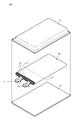
- FIG. 1 is an exploded perspective view illustrating an example of a configuration of a nonaqueous electrolyte secondary battery according to a first embodiment of the present invention.
- FIG. 2 is a sectional view taken along the line II-II of FIG. 1. It is a graph which shows an example of a DSC curve of a fluorinated binder. It is a block diagram showing an example of composition of electronic equipment concerning a 2nd embodiment of the present invention.
- FIG. 1 shows an example of a configuration of a nonaqueous electrolyte secondary battery (hereinafter, simply referred to as “battery”) according to the first embodiment of the present invention.
- the battery is a so-called laminated battery, in which the electrode body 20 to which the positive electrode lead 11 and the negative electrode lead 12 are attached is housed inside the film-shaped exterior material 10, and can be reduced in size, weight, and thickness. It has become.
- the positive electrode lead 11 and the negative electrode lead 12 are respectively directed from the inside of the exterior material 10 to the outside, for example, in the same direction.
- Each of the positive electrode lead 11 and the negative electrode lead 12 is made of, for example, a metal material such as Al, Cu, Ni, or stainless steel, and has a thin plate shape or a mesh shape, respectively.
- the outer package 10 is made of, for example, a rectangular aluminum laminate film in which a nylon film, an aluminum foil, and a polyethylene film are laminated in this order.
- the exterior material 10 is disposed, for example, such that the polyethylene film side and the electrode body 20 face each other, and the respective outer edges are adhered to each other by fusion bonding or an adhesive.
- An adhesive film 13 is inserted between the exterior material 10 and the positive electrode lead 11 and the negative electrode lead 12 to suppress invasion of outside air.
- the adhesive film 13 is made of a material having adhesiveness to the positive electrode lead 11 and the negative electrode lead 12, for example, a polyolefin resin such as polyethylene, polypropylene, modified polyethylene or modified polypropylene.
- the packaging material 10 may be made of a laminated film having another structure, a polymer film such as polypropylene, or a metal film, instead of the above-described aluminum laminated film.
- a polymer film such as polypropylene
- a metal film instead of the above-described aluminum laminated film.
- it may be constituted by a laminate film in which a polymer film is laminated on one or both sides of an aluminum film as a core material.
- FIG. 2 is a cross-sectional view of the electrode body 20 shown in FIG. 1 along the line II-II.
- the electrode body 20 is of a wound type, and has a configuration in which a long positive electrode 21 and a long negative electrode 22 are laminated via a long separator 23 and wound flat and spirally. The outermost peripheral portion is protected by a protective tape 24.
- An electrolytic solution as an electrolyte is injected into the exterior material 10 and impregnated in the positive electrode 21, the negative electrode 22, and the separator 23.
- a laminated electrode body stacked electrode body in which a positive electrode and a negative electrode are laminated with a separator interposed therebetween may be used.
- the positive electrode 21 includes, for example, a positive electrode current collector 21A and positive electrode active material layers 21B provided on both surfaces of the positive electrode current collector 21A.
- the positive electrode current collector 21A is made of, for example, a metal foil such as an aluminum foil, a nickel foil, or a stainless steel foil.
- the positive electrode current collector 21A may have a plate shape or a mesh shape.
- the cathode lead 11 may be configured by extending a part of the periphery of the cathode current collector 21A.
- the positive electrode active material layer 21B contains a positive electrode active material, a binder, and a conductive auxiliary.
- the positive electrode active material includes secondary particles in which primary particles are aggregated. From the viewpoint of improving the conductivity of the positive electrode active material, a carbon material is preferably provided on the surface of the primary particles.
- the carbon material may be scattered on the surface of the primary particles, or may cover the surface of the primary particles.
- the coating may partially cover the surface of the primary particles in the form of islands or patches, or may cover the entire surface of the primary particles.
- the primary particles include, for example, a lithium phosphate compound having an olivine type structure.
- the average composition of the positive electrode active material is represented by, for example, formula (A).
- Li x MPO 4 ⁇ ⁇ ⁇ (A) (However, in the formula (A), M is Co, Mg, Fe, Ni, Mg, Al, B, Ti, V, Nb, Cu, Zn, Mo, Ca, Sr, W and Zr) And z is a value in the range of 0.9 ⁇ x ⁇ 1.1.
- the composition of lithium differs depending on the state of charge and discharge, and the value of x is a value in a completely discharged state. Represents.)
- the average particle diameter D 1 of the primary particles is preferably 50 nm or more and 1.8 ⁇ m or less.
- the average particle diameter D 1 of the primary particles is less than 50 nm, due to the lack of amount of binder for binding the primary particles with each other, the secondary particles are easily broken by the charge and discharge cycles. Therefore, the internal resistance increases with the charge / discharge cycle.
- the positive electrode active material layer 21B contains many primary particles having a small particle size, the amount of binder for bonding between the positive electrode current collector 21A and the positive electrode active material layer 21B is insufficient. The adhesiveness between the positive electrode active material layers 21B decreases.
- the amount of the binder binding the secondary particles is also insufficient, the decrease in the conductive path between the secondary particles due to the charge / discharge cycle cannot be suppressed.
- the average particle diameter D 1 of the primary particles exceeds 1.8 ⁇ m, the amount of binder entering the secondary particles (that is, the voids between the aggregated primary particles) decreases, so that the positive electrode current collector 21A-the positive electrode active material layer
- the amount of binder that binds between the electrodes 21B increases, the adhesion between the positive electrode current collector 21A and the positive electrode active material layer 21B can be further improved, but the resistance of the positive electrode active material itself increases, so The internal resistance increases with the discharge cycle.
- the average particle diameter D 1 of the primary particles is determined as follows. First, the battery is disassembled and the positive electrode 21 is taken out. The taken out positive electrode 21 is washed with dimethyl carbonate (DMC) and dried, and then the positive electrode 21 is cut and a sample piece is collected. Subsequently, a cross section of the sample piece is photographed using an SEM (Scanning Electron Microscope) at an acceleration voltage of 5 kV and a magnification of 50,000 times. Then, ten primary particles are randomly selected from the photographed cross-sectional SEM image, the area of the particle cross section is measured by image processing, and the particle size (diameter) of each primary particle is assumed assuming that the cross section of the primary particle is circular. Ask for. Finally, the average particle diameter of the 30 primary particles measured is simply averaged (arithmetic average) to obtain an average particle diameter, which is referred to as an average primary particle diameter D 1 .
- DMC dimethyl carbonate
- the average particle diameter D 2 of the secondary particles is preferably 2 ⁇ m or more and 15 ⁇ m or less.
- the binder easily enters the inside of the secondary particles, the binding property between the primary particles is further improved, and the secondary particles are less likely to be broken by the cycle. . Therefore, it is possible to further suppress an increase in internal resistance due to a charge / discharge cycle.
- the amount of the binder bonding between the positive electrode current collector 21A and the positive electrode active material layer 21B is insufficient, the adhesiveness between the positive electrode current collector 21A and the positive electrode active material layer 21B is reduced.
- the amount of the binder binding the secondary particles is also insufficient, the decrease in the conductive path between the secondary particles due to the charge / discharge cycle cannot be suppressed.
- the average particle diameter D 2 of the secondary particles exceeds 15 ⁇ m, it becomes difficult for the binder to enter the inside of the secondary particles, so that the amount of the binder binding between the positive electrode current collector 21A and the positive electrode active material layer 21B increases.
- the adhesiveness between the positive electrode current collector 21A and the positive electrode active material layer 21B can be further improved.
- the amount of the binder binding the primary particles to each other inside the secondary particles is insufficient, the secondary particles are easily broken by a charge / discharge cycle. Therefore, the internal resistance increases with the charge / discharge cycle.
- the average particle diameter D 2 of the secondary particles is the same as that described above except that a cross-sectional SEM image of the sample piece is photographed at an acceleration voltage of 5 kV and a magnification of 5,000, and ten secondary particles are randomly selected from the photographed SEM images. , obtained in the same manner as in the average particle diameter D 1 of the above-described primary particles.
- the binder includes a fluorine-based binder.
- the upper limit of the melting point of the fluorine-based binder is 166 ° C or less, preferably 160 ° C or less.
- the melting point of the fluorine-based binder exceeds 166 ° C., when the positive electrode active material layer 21 ⁇ / b> B is dried (heat treated) in the manufacturing process of the positive electrode 21, the binder is not easily melted, and the surface of the secondary particles is formed with a wide and thin binder film. No coating is possible.
- the adhesiveness between the positive electrode current collector 21A and the positive electrode active material layer 21B is reduced, and the binding property between the secondary particles is reduced, thereby suppressing a decrease in the conductive path between the secondary particles due to the charge / discharge cycle. You can't do that.
- the binder is not easily melted, the binder is less likely to enter the secondary particles (that is, the voids between the aggregated primary particles), so that the binding property between the primary particles is reduced, and the secondary particles are easily broken by a cycle. Become. Therefore, it is not possible to suppress an increase in internal resistance due to a charge / discharge cycle.
- battery characteristics such as charge / discharge cycle characteristics are reduced.
- the lower limit of the melting point of the fluorine-based binder is not particularly limited, it is, for example, 152 ° C. or higher.
- the melting point of the above-mentioned fluorine-based binder is measured, for example, as follows. First, the positive electrode 21 is taken out of the battery, washed and dried with dimethyl carbonate (DMC), then the positive electrode current collector 21A is removed, and heated and stirred in an appropriate dispersion medium (for example, N-methylpyrrolidone or the like). , Dissolve the binder. Thereafter, the positive electrode active material is removed by centrifugation, and the remaining supernatant is filtered and evaporated to dryness, or the remaining supernatant is mixed with a solvent (eg, water) in which the binder cannot be dissolved to reprecipitate the binder. . Thereby, the binder can be taken out.
- DMC dimethyl carbonate
- an appropriate dispersion medium for example, N-methylpyrrolidone or the like.
- the sample (the removed binder) was heated at a heating rate of 1 to 10 ° C./min by a differential scanning calorimeter (DSC, Rigaku Thermoplus plus DSC8230, manufactured by Rigaku Corporation).
- DSC differential scanning calorimeter
- the temperature showing the maximum endothermic amount is defined as the melting point of the fluorine-based binder.
- a temperature at which a polymer becomes fluid by heating and heating is defined as a melting point.
- the fluorine-based binder for example, it is preferable to use polyvinylidene fluoride (PVdF) from the viewpoint of improving chemical stability and adhesiveness in a battery.
- the polyvinylidene fluoride it is preferable to use a homopolymer of vinylidene fluoride (VdF).
- VdF vinylidene fluoride
- the polyvinylidene fluoride a copolymer of vinylidene fluoride (VdF) and another monomer can be used.
- the polyvinylidene fluoride which is a copolymer, swells and dissolves in the electrolytic solution. The characteristics of the positive electrode 21 may be deteriorated because the bonding is easy and the binding force is weak.
- the polyvinylidene fluoride one obtained by modifying a part of the terminal or the like with a carboxylic acid such as maleic acid may be used.
- the content of the fluorine-based binder in the positive electrode active material layer 21B is 0.7% by mass to 4.0% by mass, preferably 2.0% by mass to 4.0% by mass, and more preferably 3.0% by mass. % Or more and 4.0% by mass or less. If the content of the fluorine-based binder is less than 0.7% by mass, the amount of the fluorine-based binder in the positive electrode active material layer 21B is insufficient, so that the surface of the secondary particles cannot be covered with a wide and thin binder film. Accordingly, the adhesiveness between the positive electrode current collector 21A and the positive electrode active material layer 21B is reduced, and the binding property between the secondary particles is reduced, thereby suppressing a decrease in the conductive path between the secondary particles due to the charge / discharge cycle.
- the content of the above-mentioned fluorine-based binder is measured as follows. First, the cathode 21 is taken out of the battery, washed with DMC, and dried. Next, a sample of several to several tens mg was subjected to 600 ° C. in an air atmosphere at a temperature rising rate of 1 to 5 ° C./min using a differential thermal balance apparatus (TG-DTA, Rigaku Thermoplus plus TG8120, manufactured by Rigaku Corporation). , And the content of the fluorine-based binder in the positive electrode active material layer 21B is determined from the weight loss at that time.
- TG-DTA Rigaku Thermoplus plus TG8120
- the amount of weight loss due to the binder can be determined by isolating the binder as described in the method for measuring the melting point of the binder, performing TG-DTA measurement of the binder alone in an air atmosphere, Can be confirmed by examining how many times they burn.
- Binders have a broad molecular weight distribution and include low and high molecular weight binders.
- the low molecular weight binder mainly has a function of entering the secondary particles (that is, the voids between the aggregated primary particles) and binding the primary particles.
- the high molecular weight binder mainly has a function of binding the secondary particles and a function of bonding between the positive electrode current collector 21A and the positive electrode active material layer 21B.
- the ratio Mw / Mn (hereinafter referred to as “dispersion degree Mw / Mn”) between the number average molecular weight Mn and the weight average molecular weight Mw of the binder is used as an index indicating the spread of the molecular weight distribution of the binder.
- the molecular weight distribution is narrow (that is, the degree of dispersion Mw / Mn is small) and the molecular weight distribution of the binder is biased toward the low-molecular side, the amount of binder entering the secondary particles is sufficient, and the Although the binding property is improved, the amount of the binder existing between the positive electrode current collector 21A and the positive electrode active material layer 21B is insufficient, so that the adhesiveness between the positive electrode current collector 21A and the positive electrode active material layer 21B is reduced. . In addition, since the amount of the binder for binding the secondary particles becomes insufficient, the binding property between the secondary particles also decreases. Therefore, battery characteristics such as charge / discharge cycle characteristics deteriorate. In the case where the adhesiveness between the positive electrode current collector 21A and the positive electrode active material layer 21B and the binding between the secondary particles are significantly reduced, an increase in internal resistance due to a charge / discharge cycle can be suppressed. Disappears.
- the molecular weight distribution is narrow (that is, the degree of dispersion Mw / Mn is small) and the molecular weight distribution of the binder is biased toward the polymer, the presence of the binder between the positive electrode current collector 21A and the positive electrode active material layer 21B is reduced.
- the amount of binder to be performed is sufficient, the adhesiveness between the positive electrode current collector 21A and the positive electrode active material layer 21B is improved, but the amount of binder that enters the secondary particles is insufficient, so that the secondary particles may be cycled. It becomes easy to collapse. Therefore, it is not possible to suppress an increase in internal resistance due to a charge / discharge cycle. Therefore, battery characteristics such as charge / discharge cycle characteristics deteriorate.
- the number average molecular weight Mn and the weight average molecular weight Mw of the binder (polymer) are represented by the following formulas (1) and (2), respectively.
- Mn ⁇ (M i ⁇ N i ) / ⁇ N i
- Mw ⁇ (M i 2 ⁇ Ni) / ⁇ (M i ⁇ N i ) (2)
- M is the molecular weight of the binder
- N is the number of the molecules of the binder.
- the degree of dispersion Mw / Mn is 2.5 or more and 5 or less. If the degree of dispersion Mw / Mn is less than 2.5, the molecular weight distribution becomes narrow, and it becomes impossible to obtain any of the effects of the low molecular weight binder and the high molecular weight binder. That is, (A) the binding property between the primary particles (that is, the effect of suppressing the internal resistance associated with the charge / discharge cycle), (B) the adhesiveness between the positive electrode current collector 21A and the positive electrode active material layer 21B, and the One of the binding properties is reduced. Therefore, battery characteristics such as charge / discharge cycle characteristics deteriorate.
- a binder having a dispersity Mw / Mn in the range of 2.5 or more and 5 or less particularly contains a low molecular weight binder as compared with a general binder, and the molecular weight distribution of the binder is broad. Since the low molecular weight binder penetrates into every corner of the secondary particles, it is possible to suppress cracking of the secondary particles even after repeated charging and discharging.
- a low-melting binder having a melting point of 152 ° C. or more and 166 ° C. or less has high fluidity, so that it can easily enter every corner of the secondary particles, which can also suppress cracking of the secondary particles.
- the weight average molecular weight Mw of the binder is preferably from 200,000 to 900,000.
- the weight average molecular weight Mw is less than 200,000, the amount of the high molecular weight binder contained in the binder decreases, and the effect of the high molecular weight binder decreases. Therefore, even if the binder has a dispersion degree Mw / Mn of 2.5 or more and 5 or less and has a wide molecular weight distribution, the adhesiveness between the positive electrode current collector 21A and the positive electrode active material layer 21B and the secondary The binding property between particles decreases. Therefore, battery characteristics such as charge / discharge cycle characteristics deteriorate.
- the binder contains a binder having an excessively high molecular weight, so that in the step of manufacturing the positive electrode 21, coating failure of the positive electrode mixture slurry occurs.
- the above-mentioned weight average molecular weight Mw and dispersity Mw / Mn are measured as follows. First, the binder is taken out of the battery in the same manner as in the method for measuring the melting point of the binder described above. Subsequently, the molecular weight of the binder taken out is calculated by a GPC method (Gel Permeation Chromatography). Specifically, for an NMP solution in which the binder powder was dissolved at 2 mg / mL, HPLC (SEC) (model number: e2695, manufactured by Waters, column: PLgel manufactured by Agilent, temperature 65 ° C., flow rate 0.7 min / mL) was used. Measure and calculate the molecular weight in terms of polyethylene oxide or polyethylene glycol. Next, using the calculated molecular weight, the weight average molecular weight Mw and the degree of dispersion Mw / Mn are calculated.
- GPC method Gel Permeation Chromatography
- the conductive additive for example, at least one carbon material of graphite, carbon fiber, carbon black, acetylene black, Ketjen black, carbon nanotube, graphene, and the like can be used.
- the conductive assistant may be any material having conductivity, and is not limited to a carbon material.
- a metal material or a conductive polymer material may be used as the conductive assistant.
- the shape of the conductive auxiliary agent include, but are not limited to, granules, scales, hollows, needles, and cylinders.
- the content of the conductive additive in the positive electrode active material layer 21B is from 0.3% by mass to 4% by mass, preferably from 1% by mass to 4% by mass, more preferably from 1% by mass to 2% by mass. . If the content of the conductive additive is less than 0.3% by mass, it is not possible to secure a favorable conductive path in the positive electrode active material layer 21B, so that the load characteristics are reduced. On the other hand, if the content of the conductive auxiliary exceeds 4% by mass, the amount of binder adsorbed on the conductive auxiliary increases, and the amount of binder for bonding between the positive electrode current collector 21A and the positive electrode active material layer 21B becomes insufficient. The adhesiveness between the positive electrode current collector 21A and the positive electrode active material layer 21B decreases.
- the content of the above-mentioned conductive additive is measured as follows. First, the cathode 21 is taken out of the battery, washed with DMC, and dried. Next, a sample of several to several tens mg was subjected to 600 ° C. in an air atmosphere at a temperature rising rate of 1 to 5 ° C./min using a differential thermal balance apparatus (TG-DTA, Rigaku Thermoplus plus TG8120, manufactured by Rigaku Corporation). Heat until Then, the content of the conductive additive is determined by subtracting the weight loss caused by the combustion reaction of the binder from the weight loss at that time.
- TG-DTA differential thermal balance apparatus
- the amount of weight loss due to the binder can be determined by isolating the binder as described in the method for measuring the melting point of the binder, performing TG-DTA measurement of the binder alone in an air atmosphere, It can be confirmed by examining at what degree C.
- the area density of the positive electrode active material layer 21B per one side of the positive electrode current collector 21A is preferably 5 mg / cm 2 or more and 25 mg / cm 2 or less.
- the area density is 5 mg / Even if it is not less than cm 2 , it is possible to suppress an increase in internal resistance due to a charge / discharge cycle. That is, when the area density of the positive electrode active material layer 21B is 5 mg / cm 2 or more, the effect of suppressing an increase in internal resistance due to a charge / discharge cycle becomes remarkable.
- the area density is 25 mg / cm 2 or less, it is possible to prevent the positive electrode 21 from becoming hard and difficult to be wound.
- the area density of the positive electrode active material layer 21B is measured as follows. First, the battery discharged to the specified voltage is disassembled, the positive electrode 21 is taken out, and dried. Next, a portion of the positive electrode 21 where the positive electrode active material layer 21B is provided on one surface is selected, and the portion is punched into a circular shape to obtain a positive electrode piece. When the positive electrode 21 does not have a portion where the positive electrode active material layer 21B is provided on one surface, the positive electrode active material layer 21B on one of the two surfaces of the positive electrode current collector 21A is N-methyl Dissolve and remove with a solvent such as -2-pyrrolidone (NMP) or dimethyl carbonate (DMC) and punch out in a circular shape to obtain a positive electrode piece.
- NMP -2-pyrrolidone
- DMC dimethyl carbonate
- the mass of the positive electrode piece is measured with an electronic balance.
- a positive electrode current collector piece is obtained by dissolving and removing the positive electrode active material layer 21B of the positive electrode piece with a solvent such as NMP or DMC.
- the mass of the positive electrode current collector piece is measured in the same manner as the positive electrode piece.
- the area [cm 2 ] of the positive electrode piece is the area of the circular main surface of the positive electrode piece.
- the thickness of the positive electrode active material layer 21B per one side of the positive electrode current collector 21A is preferably 15 ⁇ m or more and 150 ⁇ m or less on one side.
- the thickness is 15 ⁇ m or more.
- the thickness of the positive electrode active material layer 21B is 150 ⁇ m or less, it is possible to suppress the positive electrode 21 from becoming hard and difficult to wind.
- the electrochemical equivalent of the negative electrode 22 or the negative electrode active material is larger than the electrochemical equivalent of the positive electrode 21.
- lithium metal does not precipitate on the negative electrode 22 during charging. Is preferred.
- the negative electrode active material examples include carbon materials such as non-graphitizable carbon, easily graphitizable carbon, graphite, pyrolytic carbons, cokes, glassy carbons, organic polymer compound fired bodies, carbon fibers, and activated carbon. Is mentioned.
- the coke includes pitch coke, needle coke, petroleum coke and the like.
- An organic polymer compound fired body is obtained by firing a polymer material such as a phenol resin or a furan resin at an appropriate temperature and carbonizing the material, and a part thereof is hardly graphitizable carbon or easily graphitizable carbon. Some are classified as.
- These carbon materials are preferable because a change in crystal structure that occurs during charge and discharge is very small, a high charge and discharge capacity can be obtained, and good cycle characteristics can be obtained.
- graphite is preferable because it has a large electrochemical equivalent and can obtain a high energy density.
- non-graphitizable carbon is preferable because excellent cycle characteristics can be obtained.
- a material having a low charge / discharge potential specifically, a material having a charge / discharge potential close to lithium metal is preferable because a high energy density of the battery can be easily realized.
- the negative electrode active material capable of increasing the capacity include a material containing at least one of a metal element and a metalloid element as a constituent element (for example, an alloy, a compound, or a mixture). If such a material is used, a high energy density can be obtained. In particular, when used together with a carbon material, high energy density can be obtained and excellent cycle characteristics can be obtained, which is more preferable.
- alloys include alloys containing one or more metal elements and one or more metalloid elements in addition to alloys composed of two or more metal elements. Further, a nonmetallic element may be included.
- the structure includes a solid solution, a eutectic (eutectic mixture), an intermetallic compound, and a structure in which two or more of them coexist.
- a negative electrode active material for example, a metal element or a metalloid element capable of forming an alloy with lithium is given.
- a metal element or a metalloid element capable of forming an alloy with lithium.
- Specific examples include Mg, B, Al, Ti, Ga, In, Si, Ge, Sn, Pb, Bi, Cd, Ag, Zn, Hf, Zr, Y, Pd and Pt. These may be crystalline or amorphous.
- the negative electrode active material a material containing a metal element or a metalloid element belonging to the group 4B in the short-periodic periodic table as a constituent element is preferable, and a material containing at least one of Si and Sn as a constituent element is more preferable. This is because Si and Sn have a large ability to insert and extract lithium and can obtain a high energy density.
- Examples of such a negative electrode active material include a simple substance, an alloy, or a compound of Si, a simple substance, an alloy, or a compound of Sn, and a material having at least one or more of them.
- Si for example, Sn, Ni, Cu, Fe, Co, Mn, Zn, In, Ag, Ti, Ge, Bi, Sb, Nb, Mo, Al
- second constituent elements other than Si examples include those containing at least one selected from the group consisting of P, Ga, and Cr.
- Sn for example, as a second constituent element other than Sn, Si, Ni, Cu, Fe, Co, Mn, Zn, In, Ag, Ti, Ge, Bi, Sb, Nb, Mo, Al
- Examples include those containing at least one selected from the group consisting of P, Ga, and Cr.
- Examples of the compound of Sn or the compound of Si include those containing O or C as a constituent element. These compounds may contain the second constituent element described above.
- the Sn-based negative electrode active material contains Co, Sn, and C as constituent elements and has a low crystallinity or an amorphous structure.
- Other negative electrode active materials include, for example, metal oxides or polymer compounds capable of inserting and extracting lithium.
- metal oxide include lithium titanium oxide containing Li and Ti, such as lithium titanate (Li 4 Ti 5 O 12 ), iron oxide, ruthenium oxide, and molybdenum oxide.
- the polymer compound include polyacetylene, polyaniline, and polypyrrole.
- binder examples include resin materials such as polyvinylidene fluoride (PVdF), polytetrafluoroethylene (PTFE), polyacrylonitrile (PAN), styrene butadiene rubber (SBR), and carboxymethyl cellulose (CMC), and these resin materials as main components. At least one selected from the group consisting of copolymers and the like is used.
- PVdF polyvinylidene fluoride
- PTFE polytetrafluoroethylene
- PAN polyacrylonitrile
- SBR styrene butadiene rubber
- CMC carboxymethyl cellulose
- the separator 23 separates the positive electrode 21 and the negative electrode 22 and allows lithium ions to pass therethrough while preventing current short circuit due to contact between the two electrodes.
- the separator 23 is made of, for example, polytetrafluoroethylene, a polyolefin resin (such as polypropylene (PP) or polyethylene (PE)), an acrylic resin, a styrene resin, a polyester resin or a nylon resin, or a porous material formed by blending these resins. It may be formed of a porous film, and may have a structure in which two or more of these porous films are laminated.
- a porous film made of polyolefin is preferable because it has an excellent short circuit prevention effect and can improve the safety of the battery by a shutdown effect.
- polyethylene is preferable as a material constituting the separator 23 because it can obtain a shutdown effect in the range of 100 ° C. or more and 160 ° C. or less and has excellent electrochemical stability.
- low-density polyethylene, high-density polyethylene, and linear polyethylene are suitably used because they have an appropriate melting temperature and are easily available.
- a material obtained by copolymerizing or blending a resin having chemical stability with polyethylene or polypropylene can be used.
- the porous membrane may have a structure of three or more layers in which a polypropylene layer, a polyethylene layer, and a polypropylene layer are sequentially laminated.
- a single-layer substrate having 100 wt% of PP or 100 wt% of PE can be used.
- the method for producing the separator 23 may be either a wet method or a dry method.
- a non-woven fabric may be used as the separator 23.
- Aramid fiber, glass fiber, polyolefin fiber, polyethylene terephthalate (PET) fiber, nylon fiber, or the like can be used as the fiber constituting the nonwoven fabric. Further, these two or more kinds of fibers may be mixed to form a nonwoven fabric.
- the separator 23 may have a configuration including a base material and a surface layer provided on one or both surfaces of the base material.
- the surface layer includes electrically insulating inorganic particles, and a resin material that binds the inorganic particles to the surface of the base material and binds the inorganic particles to each other.
- This resin material may be, for example, fibrillated and have a three-dimensional network structure in which a plurality of fibrils are connected.
- the inorganic particles are supported on the resin material having the three-dimensional network structure.
- the resin material may bind the surface of the base material or the inorganic particles without fibrillation. In this case, higher binding properties can be obtained.
- the base material is a porous film composed of an insulating film that transmits lithium ions and has a predetermined mechanical strength. Since the electrolyte solution is held in the pores of the base material, the base material has resistance to the electrolyte solution. , High reactivity, low reactivity, and difficulty in expanding.
- the above-described resin material or nonwoven fabric forming the separator 23 can be used.
- the inorganic particles include at least one selected from the group consisting of metal oxides, metal nitrides, metal carbides, metal sulfides, and the like.
- the metal oxide include aluminum oxide (alumina, Al 2 O 3 ), boehmite (hydrated aluminum oxide), magnesium oxide (magnesia, MgO), titanium oxide (titania, TiO 2 ), and zirconium oxide (zirconia, ZrO 2). ), Silicon oxide (silica, SiO 2 ) or yttrium oxide (yttria, Y 2 O 3 ) or the like can be suitably used.
- silicon nitride Si 3 N 4
- aluminum nitride AlN
- boron nitride BN
- titanium nitride TiN
- metal carbide silicon carbide (SiC) or boron carbide (B 4 C)
- metal sulfide barium sulfate (BaSO 4 ) or the like can be suitably used.
- alumina titania (especially those having a rutile structure), silica or magnesia, and more preferably to use alumina.
- the inorganic particles are made of a porous aluminosilicate such as zeolite (M 2 / n O.Al 2 O 3 .xSiO 2 .yH 2 O, M is a metal element, x ⁇ 2, y ⁇ 0); Salts, minerals such as barium titanate (BaTiO 3 ) or strontium titanate (SrTiO 3 ) may be included.
- the inorganic particles have oxidation resistance and heat resistance, and the surface layer on the side facing the positive electrode containing the inorganic particles has strong resistance to an oxidizing environment near the positive electrode during charging.
- the shape of the inorganic particles is not particularly limited, and any of a spherical shape, a plate shape, a fibrous shape, a cubic shape, and a random shape can be used.
- the particle size of the inorganic particles is preferably in the range of 1 nm to 10 ⁇ m. If the thickness is less than 1 nm, it is difficult to obtain, and if the thickness is more than 10 ⁇ m, the distance between the electrodes becomes large, so that a sufficient amount of active material cannot be obtained in a limited space, and the battery capacity is reduced.
- the resin material constituting the surface layer examples include fluorine-containing resins such as polyvinylidene fluoride and polytetrafluoroethylene, fluorine-containing rubbers such as vinylidene fluoride-tetrafluoroethylene copolymer and ethylene-tetrafluoroethylene copolymer, and styrene.
- fluorine-containing resins such as polyvinylidene fluoride and polytetrafluoroethylene
- fluorine-containing rubbers such as vinylidene fluoride-tetrafluoroethylene copolymer and ethylene-tetrafluoroethylene copolymer
- styrene examples include polystyrene.
- -Butadiene copolymer or hydride thereof acrylonitrile-butadiene copolymer or hydride thereof, acrylonitrile-butadiene-styrene copolymer or hydride thereof, methacrylate-acrylate copolymer, styrene-acrylate Copolymers, acrylonitrile-acrylate copolymers, rubbers such as ethylene propylene rubber, polyvinyl alcohol, polyvinyl acetate, etc., ethyl cellulose, methyl cellulose, hydroxyethyl cellulose, carboxymethyl Cellulose derivatives such as cellulose, polyphenylene ether, polysulfone, polyethersulfone, polyphenylene sulfide, polyetherimide, polyimide, polyamide such as wholly aromatic polyamide (aramid), polyamideimide, polyacrylonitrile, polyvinyl alcohol, polyether, acrylic resin Alternatively, a resin having high heat resistance such as polyester having at least one
- resin materials may be used alone or as a mixture of two or more.
- a fluororesin such as polyvinylidene fluoride is preferable, and from the viewpoint of heat resistance, it is preferable to contain aramid or polyamideimide.
- a slurry composed of a matrix resin, a solvent, and inorganic particles is applied on a substrate (porous film), and the slurry is passed through a poor solvent for the matrix resin and a solvent-friendly bath of the solvent.
- a method of phase separation and then drying can be used.
- the inorganic particles described above may be contained in a porous film as a substrate. Further, the surface layer may not include the inorganic particles, and may be formed only of the resin material.
- the electrolyte is a so-called non-aqueous electrolyte, and includes an organic solvent (non-aqueous solvent) and an electrolyte salt dissolved in the organic solvent.
- the electrolytic solution may contain a known additive in order to improve battery characteristics. Note that, instead of the electrolytic solution, an electrolytic layer containing the electrolytic solution and a polymer compound serving as a holder for holding the electrolytic solution may be used. In this case, the electrolyte layer may be in a gel state.
- a cyclic carbonate such as ethylene carbonate or propylene carbonate can be used, and it is preferable to use one of ethylene carbonate and propylene carbonate, particularly a mixture of both. This is because the cycle characteristics can be further improved.
- organic solvent it is preferable to use a mixture of chain carbonates such as diethyl carbonate, dimethyl carbonate, ethylmethyl carbonate and methylpropyl carbonate in addition to these cyclic carbonates. This is because high ionic conductivity can be obtained.
- the organic solvent further contains 2,4-difluoroanisole or vinylene carbonate. This is because 2,4-difluoroanisole can further improve the discharge capacity, and vinylene carbonate can further improve the cycle characteristics. Therefore, it is preferable to use a mixture of these, because the discharge capacity and cycle characteristics can be further improved.
- organic solvents include butylene carbonate, ⁇ -butyrolactone, ⁇ -valerolactone, 1,2-dimethoxyethane, tetrahydrofuran, 2-methyltetrahydrofuran, 1,3-dioxolan, and 4-methyl-1,3 -Dioxolan, methyl acetate, methyl propionate, acetonitrile, glutaronitrile, adiponitrile, methoxyacetonitrile, 3-methoxypropironitrile, N, N-dimethylformamide, N-methylpyrrolidinone, N-methyloxazolidinone, N, N- Examples thereof include dimethylimidazolidinone, nitromethane, nitroethane, sulfolane, dimethylsulfoxide, and trimethyl phosphate.
- Examples of the electrolyte salt include a lithium salt, and one kind may be used alone, or two or more kinds may be used in combination.
- the lithium salt LiPF 6, LiBF 4, LiAsF 6, LiClO 4, LiB (C 6 H 5) 4, LiCH 3 SO 3, LiCF 3 SO 3, LiN (SO 2 CF 3) 2, LiC (SO 2 CF 3 ) 3 , LiAlCl 4 , LiSiF 6 , LiCl, lithium difluoro [oxolate-O, O ′] borate, lithium bisoxalate borate, or LiBr.
- LiPF 6 is preferable because high ion conductivity can be obtained and cycle characteristics can be further improved.
- the positive electrode 21 is manufactured as follows. First, for example, a positive electrode mixture is prepared by mixing a positive electrode active material, a binder, and a conductive auxiliary, and the positive electrode mixture is dispersed in a solvent such as N-methyl-2-pyrrolidone (NMP) to form a paste. A positive electrode mixture slurry is prepared. Next, the positive electrode mixture slurry is applied to the positive electrode current collector 21A, the solvent is dried, and compression molding is performed by a roll press or the like to form the positive electrode active material layer 21B, and the positive electrode 21 is obtained.
- NMP N-methyl-2-pyrrolidone
- the negative electrode 22 is manufactured as follows. First, for example, a negative electrode mixture is prepared by mixing a negative electrode active material and a binder, and this negative electrode mixture is dispersed in a solvent such as N-methyl-2-pyrrolidone to prepare a paste-like negative electrode mixture slurry. I do. Next, the negative electrode mixture slurry is applied to the negative electrode current collector 22A, the solvent is dried, and compression molding is performed by a roll press or the like to form the negative electrode active material layer 22B, and the negative electrode 22 is obtained.
- a negative electrode mixture is prepared by mixing a negative electrode active material and a binder, and this negative electrode mixture is dispersed in a solvent such as N-methyl-2-pyrrolidone to prepare a paste-like negative electrode mixture slurry. I do.
- the negative electrode mixture slurry is applied to the negative electrode current collector 22A, the solvent is dried, and compression molding is performed by a roll press or the like to form the negative electrode active material layer 22B, and the negative electrode 22 is
- the wound electrode body 20 is manufactured as follows. First, the cathode lead 11 is attached to one end of the cathode current collector 21A by welding, and the anode lead 12 is attached to one end of the anode current collector 22A by welding. Next, the positive electrode 21 and the negative electrode 22 are wound around a flat core with a separator 23 interposed therebetween, and are wound many times in the longitudinal direction. Get.
- the exterior body 10 seals the electrode body 20 as follows. First, the electrode body 20 is sandwiched between the package members 10, and the outer peripheral edge portion excluding one side is heat-fused into a bag shape, and is housed inside the package member 10. At that time, an adhesive film 13 is inserted between the positive electrode lead 11 and the negative electrode lead 12 and the exterior material 10. Note that the adhesive film 13 may be attached to each of the positive electrode lead 11 and the negative electrode lead 12 in advance. Next, after injecting the electrolytic solution into the exterior material 10 from one side of the unfused part, one side of the unfused part is heat-sealed in a vacuum atmosphere to be sealed. Thus, the batteries shown in FIGS. 1 and 2 are obtained.
- the positive electrode 21 includes a positive electrode current collector 21A and a positive electrode active material layer 21B provided on the positive electrode current collector 21A.
- the positive electrode active material layer 21B contains a positive electrode active material, a fluorine-based binder having a melting point of 152 ° C. or more and 166 ° C. or less, and a conductive auxiliary.
- the positive electrode active material includes secondary particles in which primary particles are aggregated.
- the dispersion degree Mw / Mn of the fluorine-based binder is 2.5 or more and 5 or less, and the weight average molecular weight Mw of the fluorine-based binder is 200,000 or more and 900,000 or less.
- the content of the fluorine-based binder in the positive electrode active material layer 21B is 0.3% by mass or more and 5% by mass or less, and the content of the conductive auxiliary in the positive electrode active material layer 21B is 0.3% by mass or more. % By mass or less. Accordingly, it is possible to suppress an increase in internal resistance due to a charge / discharge cycle and to suppress a decrease in adhesiveness between the positive electrode current collector 21A and the positive electrode active material layer 21B.
- FIG. 4 shows an example of the configuration of an electronic device 400 according to the second embodiment of the present invention.
- the electronic device 400 includes an electronic circuit 401 of the electronic device main body and the battery pack 300.
- Battery pack 300 is electrically connected to electronic circuit 401 via positive electrode terminal 331a and negative electrode terminal 331b.
- the electronic device 400 may have a configuration in which the battery pack 300 is detachable.
- Examples of the electronic device 400 include a notebook personal computer, a tablet computer, a mobile phone (for example, a smartphone), a portable information terminal (Personal Digital Assistants: PDA), a display device (LCD (Liquid Crystal Display), and an EL (Electro Luminescence).
- a notebook personal computer for example, a tablet computer
- a mobile phone for example, a smartphone
- a portable information terminal Personal Digital Assistants: PDA
- a display device LCD (Liquid Crystal Display)
- EL Electro Luminescence
- imaging device eg, digital still camera, digital video camera, etc.
- audio equipment eg, portable audio player
- game equipment e.g., cordless phone handset, electronic book, electronic dictionary, radio, headphone, navigation System, memory card, pacemaker, hearing aid, power tool, electric shaver, refrigerator, air conditioner, TV, stereo, water heater, microwave oven, dishwasher, washing machine, dryer, lighting equipment, toy, medical equipment, robot Load conditioners, although traffic signals and the like, without such limited thereto.
- the electronic circuit 401 includes, for example, a CPU (Central Processing Unit), a peripheral logic unit, an interface unit, a storage unit, and the like, and controls the entire electronic device 400.
- a CPU Central Processing Unit
- the battery pack 300 includes an assembled battery 301 and a charge / discharge circuit 302. Battery pack 300 may further include an exterior material (not shown) that accommodates assembled battery 301 and charge / discharge circuit 302 as necessary.
- the assembled battery 301 is configured by connecting a plurality of secondary batteries 301a in series and / or in parallel.
- the plurality of secondary batteries 301a are connected in, for example, n parallel and m series (n and m are positive integers).
- FIG. 4 shows an example in which six secondary batteries 301a are connected in two parallel and three series (2P3S).
- the secondary battery 301a the battery according to the above-described first embodiment is used.
- the battery pack 300 includes an assembled battery 301 including a plurality of secondary batteries 301a.
- the battery pack 300 includes a single secondary battery 301a instead of the assembled battery 301. May be adopted.
- the charging / discharging circuit 302 is a control unit that controls charging / discharging of the battery pack 301. Specifically, at the time of charging, the charge / discharge circuit 302 controls charging of the battery pack 301. On the other hand, at the time of discharging (that is, at the time of using the electronic device 400), the charging / discharging circuit 302 controls discharging to the electronic device 400.
- the exterior material for example, a case made of a metal, a polymer resin, or a composite material thereof can be used.
- the composite material include a laminate in which a metal layer and a polymer resin layer are laminated.
- the dispersion degree Mw / Mn of polyvinylidene fluoride, the weight average molecular weight Mw, the melting point Tm, the average particle diameter D 1 of the primary particles, and the average particle diameter D 2 of the secondary particles are the above-mentioned first values. Are obtained by the method described in the embodiment.
- a positive electrode was produced as follows. 97% by mass of LiFePO 4 (average particle diameter D 1 of primary particles: 0.3 ⁇ m, average particle diameter D 2 of secondary particles: 8 ⁇ m) as a positive electrode active material, and polyvinylidene fluoride (homopolymer of vinylidene fluoride) as a binder After mixing 1% by mass and 2% by mass of Ketjen black as a conductive additive to form a positive electrode mixture, this positive electrode mixture was dispersed in an organic solvent (N-methyl-2-pyrrolidone: NMP). Then, a paste-like positive electrode mixture slurry was obtained.
- LiFePO 4 average particle diameter D 1 of primary particles: 0.3 ⁇ m, average particle diameter D 2 of secondary particles: 8 ⁇ m
- polyvinylidene fluoride homopolymer of vinylidene fluoride
- the dispersion degree Mw / Mn of polyvinylidene fluoride was changed in the range of 1.6 to 6.1, the weight average molecular weight Mw was changed in the range of 150,000 to 120000000, and the melting point Tm was changed in the range of 152 to 175 ° C.
- the positive electrode mixture slurry was applied to the positive electrode current collector (aluminum foil) using a coating device, and then dried to form a positive electrode active material layer. Finally, the positive electrode active material layer was compression-molded using a press.
- a negative electrode was manufactured as follows. First, a negative electrode mixture was prepared by mixing 96% by mass of artificial graphite powder as a negative electrode active material and 4% by mass of polyvinylidene fluoride (PVdF) as a binder. Then, the negative electrode mixture was mixed with an organic solvent (N-methyl- 2-pyrrolidone: NMP) to give a paste-like negative electrode mixture slurry. Subsequently, the negative electrode mixture slurry was applied to the negative electrode current collector (copper foil) using a coating device and then dried. Finally, the negative electrode active material layer was compression molded using a press.
- PVdF polyvinylidene fluoride
- EC ethylene carbonate
- PC propylene carbonate
- DEC diethyl carbonate
- a laminated battery was manufactured as follows. First, a positive electrode lead made of aluminum was welded to the positive electrode current collector, and a negative electrode lead made of copper was welded to the negative electrode current collector. Subsequently, after the positive electrode and the negative electrode are adhered to each other via a microporous polyethylene film, they are wound in the longitudinal direction, and a protective tape is attached to the outermost peripheral portion, thereby producing a flat-shaped wound electrode body. did. Next, this wound electrode body was loaded between the package members, and three sides of the package member were heat-sealed, and one side was not heat-sealed and had an opening.
- a moisture-proof aluminum laminated film in which a nylon film having a thickness of 25 ⁇ m, an aluminum foil having a thickness of 40 ⁇ m, and a polypropylene film having a thickness of 30 ⁇ m were laminated in this order from the outermost layer was used.
- Examples 6 to 8, Comparative Examples 12 and 13 In the positive electrode preparation process, as shown in Table 2, the amount of the binder was changed in the range of 0.2 to 7.0% by mass, and the amount of the positive electrode active material was changed in the range of 97.8 to 91.0% by mass. A battery was obtained in the same manner as in Example 1, except that the amount of the conductive additive was maintained at 2% by mass.
- Examples 9 to 11, Comparative Examples 14 and 15 In the positive electrode preparation step, as shown in Table 3, the compounding amount of the conductive additive was in the range of 0.2 to 6.0% by mass, and the compounding amount of the positive electrode active material was in the range of 93.0 to 98.8% by mass. A battery was obtained in the same manner as in Example 1 except that the amount of the binder was changed to 1.0% by mass.
- Example 12 to 15 In the process for producing the positive electrode, as shown in Table 4, while maintaining the average particle diameter D 1 of the primary particles at 0.2 ⁇ m, the average particle diameter D 2 of the secondary particles was in the range of 1.3 to 19.8 ⁇ m. A battery was obtained in the same manner as in Example 1, except for the change.
- Examples 16 to 19 In the positive electrode fabrication process, as shown in Table 4, the average particle diameter D 1 of the primary particles was changed in the range of 0.05 to 3.5 ⁇ m, and the average particle diameter D 2 of the secondary particles was 7.5 to A battery was obtained in the same manner as in Example 1, except that the thickness was changed within the range of 8.5 ⁇ m.
- Table 1 shows the following.
- the dispersion degree Mw / Mn is less than 2.5 and the weight-average molecular weight Mw of the fluorine-based binder is low, that is, when the fluorine-based binder is almost composed of a low-molecular-weight binder, the impedance rise rate is large and the peel strength is reduced.
- the degree of dispersion Mw / Mn is less than 2.5 and the weight average molecular weight Mw of the fluorine-based binder is high, a decrease in peel strength can be suppressed, but the rate of increase in impedance increases (Examples). 1 to 5, Comparative Example 3).
- the degree of dispersion Mw / Mn exceeds 5.0, coating failure occurs (see Examples 1 to 5 and Comparative Example 5).
- the degree of dispersion Mw / Mn is 2.5 or more and 5 or less, and the weight-average molecular weight Mw of the fluorine-based binder is 200,000 or more. Even if it is 900,000 or less, the impedance rise rate is large and the peel strength decreases (see Examples 1 to 5 and Comparative Example 7).
- Table 2 shows the following.
- the content of the fluorine-based binder in the positive electrode active material layer is less than 0.3% by mass, the peel strength decreases.
- the content of the binder in the positive electrode active material layer exceeds 5.0% by mass, the load characteristics deteriorate.
- Table 3 shows the following.
- the content of the conductive auxiliary agent in the positive electrode active material layer is less than 0.3% by mass, the load characteristics deteriorate.
- the content of the conductive additive in the positive electrode active material layer exceeds 4% by mass, the peel strength decreases.
- Table 4 shows the following.
- the average particle diameter D 1 of the primary particles is less than 50 nm, the impedance increase rate is increased, and the peeling strength is lowered.
- the average particle diameter D 1 of the primary particles is more than 1.8 .mu.m, the impedance increase rate increases.
- the peel strength decreases.
- the average particle diameter D 2 of the secondary particles exceeds 15 ⁇ m, the rate of increase in impedance increases.
- the average particle diameter D 1 of the primary particles is set to 50 nm or more and 1.8 ⁇ m or less, 8) It is understood that it is preferable that the average particle diameter D2 of the secondary particles be 2 ⁇ m or more and 15 ⁇ m or less.
Abstract
La présente invention concerne une batterie secondaire qui comporte une électrode positive, une électrode négative et un électrolyte. L'électrode positive comporte un collecteur de courant d'électrode positive et une couche de matériau actif d'électrode positive disposée sur le collecteur de courant d'électrode positive. La couche de matériau actif d'électrode positive comprend un matériau actif d'électrode positive, un liant à base de fluor ayant un point de fusion de 152 à 166 °C, et un agent auxiliaire conducteur. Le matériau actif d'électrode positive comprend des particules secondaires dans lesquelles des particules primaires sont agrégées, et le rapport Mw/Mn du poids moléculaire moyen en poids Mw sur le poids moléculaire moyen en nombre Mn du liant à base de fluor est de 2,5 à 5, le poids moléculaire moyen en poids Mw est de 200000 à 900000, la teneur du liant à base de fluor dans la couche de matériau actif d'électrode positive est de 0,3 à 5 % en masse, et la teneur en agent auxiliaire conducteur dans la couche de matériau actif d'électrode positive est de 0,3 à 4 % en masse.
Applications Claiming Priority (2)
| Application Number | Priority Date | Filing Date | Title |
|---|---|---|---|
| JP2018175437 | 2018-09-19 | ||
| JP2018-175437 | 2018-09-19 |
Publications (1)
| Publication Number | Publication Date |
|---|---|
| WO2020059802A1 true WO2020059802A1 (fr) | 2020-03-26 |
Family
ID=69888482
Family Applications (1)
| Application Number | Title | Priority Date | Filing Date |
|---|---|---|---|
| PCT/JP2019/036777 WO2020059802A1 (fr) | 2018-09-19 | 2019-09-19 | Batterie secondaire |
Country Status (1)
| Country | Link |
|---|---|
| WO (1) | WO2020059802A1 (fr) |
Citations (4)
| Publication number | Priority date | Publication date | Assignee | Title |
|---|---|---|---|---|
| JPH0927313A (ja) * | 1995-07-10 | 1997-01-28 | Ricoh Co Ltd | 非水電解液二次電池 |
| JP2009277661A (ja) * | 2007-11-30 | 2009-11-26 | Sony Corp | 正極活物質、正極および非水電解質二次電池 |
| JP2014165037A (ja) * | 2013-02-26 | 2014-09-08 | Murata Mfg Co Ltd | 非水電解質二次電池用電極材料とそれを用いた非水電解質二次電池 |
| JP2015005481A (ja) * | 2013-06-24 | 2015-01-08 | ソニー株式会社 | 二次電池およびその製造方法、ならびに電池パック、電動車両、電力貯蔵システム、電動工具および電子機器 |
-
2019
- 2019-09-19 WO PCT/JP2019/036777 patent/WO2020059802A1/fr active Application Filing
Patent Citations (4)
| Publication number | Priority date | Publication date | Assignee | Title |
|---|---|---|---|---|
| JPH0927313A (ja) * | 1995-07-10 | 1997-01-28 | Ricoh Co Ltd | 非水電解液二次電池 |
| JP2009277661A (ja) * | 2007-11-30 | 2009-11-26 | Sony Corp | 正極活物質、正極および非水電解質二次電池 |
| JP2014165037A (ja) * | 2013-02-26 | 2014-09-08 | Murata Mfg Co Ltd | 非水電解質二次電池用電極材料とそれを用いた非水電解質二次電池 |
| JP2015005481A (ja) * | 2013-06-24 | 2015-01-08 | ソニー株式会社 | 二次電池およびその製造方法、ならびに電池パック、電動車両、電力貯蔵システム、電動工具および電子機器 |
Similar Documents
| Publication | Publication Date | Title |
|---|---|---|
| JP5699576B2 (ja) | 積層型微多孔膜、電池用セパレータおよび非水電解質電池 | |
| US11398660B2 (en) | Flame retardant separator having asymmetric structure for secondary batteries | |
| JP5359444B2 (ja) | リチウムイオン二次電池 | |
| WO2020059803A1 (fr) | Batterie secondaire | |
| US20210043941A1 (en) | Battery | |
| CN113892201A (zh) | 负极活性物质、负极以及二次电池 | |
| JP2018147769A (ja) | 電気化学素子用セパレータおよび非水電解質電池 | |
| US20210210789A1 (en) | Secondary battery | |
| JP5213003B2 (ja) | 非水電解質二次電池 | |
| WO2018097316A1 (fr) | Électrode négative, batterie, bloc-batterie, dispositif électronique, véhicule électrique, dispositif de stockage d'électricité et système d'alimentation électrique | |
| JP2019164965A (ja) | リチウムイオン二次電池 | |
| WO2019208806A1 (fr) | Batterie | |
| US11929485B2 (en) | Secondary battery | |
| JP6855882B2 (ja) | 正極、及びリチウムイオン二次電池 | |
| WO2020059874A1 (fr) | Batterie secondaire | |
| WO2020059802A1 (fr) | Batterie secondaire | |
| WO2020218019A1 (fr) | Matériau actif d'électrode négative, électrode négative et batterie secondaire | |
| US20210159540A1 (en) | Nonaqueous electrolyte secondary battery | |
| US20240047828A1 (en) | Non-aqueous electrolyte secondary battery | |
| WO2020059873A1 (fr) | Batterie secondaire | |
| WO2019017344A1 (fr) | Matériau actif d'électrode positive, électrode positive, batterie, bloc-batterie, dispositif électronique, véhicule électrique, dispositif de stockage d'énergie et système d'alimentation | |
| JP7099548B2 (ja) | 非水電解液および非水電解質二次電池 | |
| JP6992578B2 (ja) | リチウムイオン二次電池用電極及びそれを用いたリチウムイオン二次電池 | |
| WO2020013324A1 (fr) | Batterie secondaire à électrolyte non aqueux | |
| JP2024514641A (ja) | リチウム二次電池用分離膜、それを含むリチウム二次電池、及び該リチウム二次電池用分離膜の製造方法 |
Legal Events
| Date | Code | Title | Description |
|---|---|---|---|
| 121 | Ep: the epo has been informed by wipo that ep was designated in this application |
Ref document number: 19862285 Country of ref document: EP Kind code of ref document: A1 |
|
| NENP | Non-entry into the national phase |
Ref country code: DE |
|
| 122 | Ep: pct application non-entry in european phase |
Ref document number: 19862285 Country of ref document: EP Kind code of ref document: A1 |
|
| NENP | Non-entry into the national phase |
Ref country code: JP |