WO2020054853A1 - 脱硝装置 - Google Patents
脱硝装置 Download PDFInfo
- Publication number
- WO2020054853A1 WO2020054853A1 PCT/JP2019/036135 JP2019036135W WO2020054853A1 WO 2020054853 A1 WO2020054853 A1 WO 2020054853A1 JP 2019036135 W JP2019036135 W JP 2019036135W WO 2020054853 A1 WO2020054853 A1 WO 2020054853A1
- Authority
- WO
- WIPO (PCT)
- Prior art keywords
- catalyst
- exhaust gas
- flow passage
- catalyst layer
- gas flow
- Prior art date
- Legal status (The legal status is an assumption and is not a legal conclusion. Google has not performed a legal analysis and makes no representation as to the accuracy of the status listed.)
- Ceased
Links
Images



Classifications
-
- B—PERFORMING OPERATIONS; TRANSPORTING
- B01—PHYSICAL OR CHEMICAL PROCESSES OR APPARATUS IN GENERAL
- B01D—SEPARATION
- B01D53/00—Separation of gases or vapours; Recovering vapours of volatile solvents from gases; Chemical or biological purification of waste gases, e.g. engine exhaust gases, smoke, fumes, flue gases, aerosols
- B01D53/34—Chemical or biological purification of waste gases
- B01D53/74—General processes for purification of waste gases; Apparatus or devices specially adapted therefor
- B01D53/86—Catalytic processes
-
- F—MECHANICAL ENGINEERING; LIGHTING; HEATING; WEAPONS; BLASTING
- F01—MACHINES OR ENGINES IN GENERAL; ENGINE PLANTS IN GENERAL; STEAM ENGINES
- F01N—GAS-FLOW SILENCERS OR EXHAUST APPARATUS FOR MACHINES OR ENGINES IN GENERAL; GAS-FLOW SILENCERS OR EXHAUST APPARATUS FOR INTERNAL-COMBUSTION ENGINES
- F01N3/00—Exhaust or silencing apparatus having means for purifying, rendering innocuous, or otherwise treating exhaust
- F01N3/02—Exhaust or silencing apparatus having means for purifying, rendering innocuous, or otherwise treating exhaust for cooling, or for removing solid constituents of, exhaust
-
- F—MECHANICAL ENGINEERING; LIGHTING; HEATING; WEAPONS; BLASTING
- F01—MACHINES OR ENGINES IN GENERAL; ENGINE PLANTS IN GENERAL; STEAM ENGINES
- F01N—GAS-FLOW SILENCERS OR EXHAUST APPARATUS FOR MACHINES OR ENGINES IN GENERAL; GAS-FLOW SILENCERS OR EXHAUST APPARATUS FOR INTERNAL-COMBUSTION ENGINES
- F01N3/00—Exhaust or silencing apparatus having means for purifying, rendering innocuous, or otherwise treating exhaust
- F01N3/08—Exhaust or silencing apparatus having means for purifying, rendering innocuous, or otherwise treating exhaust for rendering innocuous
-
- F—MECHANICAL ENGINEERING; LIGHTING; HEATING; WEAPONS; BLASTING
- F01—MACHINES OR ENGINES IN GENERAL; ENGINE PLANTS IN GENERAL; STEAM ENGINES
- F01N—GAS-FLOW SILENCERS OR EXHAUST APPARATUS FOR MACHINES OR ENGINES IN GENERAL; GAS-FLOW SILENCERS OR EXHAUST APPARATUS FOR INTERNAL-COMBUSTION ENGINES
- F01N3/00—Exhaust or silencing apparatus having means for purifying, rendering innocuous, or otherwise treating exhaust
- F01N3/08—Exhaust or silencing apparatus having means for purifying, rendering innocuous, or otherwise treating exhaust for rendering innocuous
- F01N3/10—Exhaust or silencing apparatus having means for purifying, rendering innocuous, or otherwise treating exhaust for rendering innocuous by thermal or catalytic conversion of noxious components of exhaust
- F01N3/24—Exhaust or silencing apparatus having means for purifying, rendering innocuous, or otherwise treating exhaust for rendering innocuous by thermal or catalytic conversion of noxious components of exhaust characterised by constructional aspects of converting apparatus
- F01N3/28—Construction of catalytic reactors
-
- F—MECHANICAL ENGINEERING; LIGHTING; HEATING; WEAPONS; BLASTING
- F23—COMBUSTION APPARATUS; COMBUSTION PROCESSES
- F23J—REMOVAL OR TREATMENT OF COMBUSTION PRODUCTS OR COMBUSTION RESIDUES; FLUES
- F23J15/00—Arrangements of devices for treating smoke or fumes
Definitions
- Patent Literature 1 discloses that a nitrogen oxide using ammonia (NH 3 ) as a reducing agent is provided before or after a NOx purification catalyst that reduces and purifies nitrogen oxides in exhaust gas using carbon monoxide or hydrocarbons in exhaust gas.
- a reducing catalyst ammonia denitration catalyst
- ammonia is blown into exhaust gas at a stage preceding the ammonia denitration catalyst.
- the concentration of carbon monoxide in the exhaust gas flowing through the denitration device is not uniform in the cross section of the flow channel, and there are low and high concentrations of the carbon monoxide.
- the reduction and removal of oxides are not effectively performed, and the effect of the carbon monoxide denitration catalyst cannot be obtained.
- arranging the carbon monoxide denitration catalyst over the entire cross section of the flow path unnecessarily increases the cost.
- a denitration apparatus includes a gas flow passage, a first catalyst layer, a second catalyst layer, and a reducing agent injection unit.
- the second catalyst layer is disposed at at least four corners of the cross section of the gas flow passage and supports the second catalyst.
- the second catalyst layer is disposed at the center of the cross section of the flow passage of the gas flow passage. It has a catalyst non-supporting region that does not support two catalysts, and is configured such that the pressure loss of flowing exhaust gas is equal in the entire region of the flow path cross section including the catalyst supporting region and the catalyst non-supporting region.
- the carbon monoxide concentration of the exhaust gas flowing into the second catalyst layer tends to be higher at four corners and lower at the center.
- the corners where the concentration of carbon monoxide is high are defined as catalyst-supporting regions, and the central portions where the concentration of carbon monoxide is low are defined as non-catalyst-supporting regions.
- the second catalyst is disposed at a corner where reduction and removal of nitrogen oxides by the second catalyst (carbon monoxide denitration catalyst) can be expected, and the second catalyst is disposed at a center where reduction and removal of nitrogen oxides cannot be expected. Since no catalyst is provided, an increase in cost due to the material cost of the second catalyst can be suppressed.
- the inlet of the second catalyst layer is The flow direction of the exhaust gas does not greatly change. For this reason, exhaust gas with a high concentration of carbon monoxide can flow through the catalyst-carrying region, and exhaust gas with a low concentration of carbon monoxide can flow through the catalyst-non-carrying region.
- a second aspect of the present invention is the denitration apparatus according to the first aspect, wherein the catalyst supporting region of the second catalyst layer is annular along the outer peripheral edge of the gas flow passage cross section, and the catalyst non-supporting region Is an inner region surrounded by an annular catalyst carrying region.
- the concentration of carbon monoxide in the exhaust gas flowing into the second catalyst layer is determined by an annular outer peripheral portion along the outer periphery of the cross section of the flow passage (at four locations). (Including corners) is high, and the inner region (central portion) surrounded by the outer peripheral edge tends to be lower.
- the outer peripheral edge having a high carbon monoxide concentration is defined as a catalyst supporting region
- the inner region where the concentration of carbon monoxide is low is defined as a catalyst non-supporting region. Therefore, the reduction and removal of nitrogen oxides can be performed in a wider range than in the case where the second catalyst is arranged only at four corners.
- a third aspect of the present invention is the denitration apparatus of the first or second aspect, further comprising an exhaust gas cooling means for cooling exhaust gas.
- the second catalyst layer is disposed in a gas flow passage downstream of the first catalyst layer, and the exhaust gas cooling unit is configured to control the exhaust gas flowing through the gas flow passage downstream of the first catalyst layer and upstream of the second catalyst layer. To cool.
- the present invention while suppressing an increase in cost, it is possible to suppress adhesion and accumulation of acidic ammonium sulfate on equipment downstream of the denitration apparatus and to reduce carbon monoxide in exhaust gas.
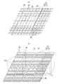
- FIG. 3A and 3B are cross-sectional views of a second catalyst layer along a flow path cross section of FIG. 2, wherein FIG. 2A shows a case where a rectangular annular outer peripheral edge is used as a catalyst supporting region, and FIG. Each case is shown as a supporting area.
- 4A is an enlarged perspective view of a portion IV in FIG. 3A, wherein FIG. 3A illustrates an example in which a second catalyst layer is configured by a porous structure, and FIG. 3B illustrates an example in which the second catalyst layer is configured by a plate-shaped catalyst unit. Are respectively shown.
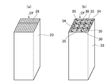
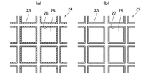
- FIG.4 It is a perspective view of the structure which comprises a 2nd catalyst layer, (a) is the porous body which comprises the porous structure of FIG.4 (a), (b) is the plate-shaped catalyst unit of FIG.4 (b). Shown respectively. It is an expanded sectional view of the 2nd catalyst layer of Drawing 5 (a), (a) shows a catalyst loading field, and (b) shows a catalyst non-loading field, respectively. It is sectional drawing of the modification of a denitration apparatus.
- a flue gas treatment system for purifying exhaust gas from a boiler (coal-fired boiler) 1 and discharging the exhaust gas to the atmosphere includes a denitration device 2, an air preheater (AH: air heater) 3, and an electric dust collector 4. And an induction draft fan 5 are provided.
- the boiler 1 may be a boiler other than coal-fired.
- the denitration device 2 is disposed downstream of the boiler 1 and reduces and removes nitrogen oxides (NOx) in exhaust gas.
- the air preheater 3 is arranged downstream of the denitration device 2 and heats combustion air by heat exchange with exhaust gas.
- the electric dust collector 4 is disposed downstream of the air preheater 3 and collects and removes dust (combustion ash) in exhaust gas.
- the induction ventilator 5 is arranged downstream of the electric precipitator 4, and attracts and guides the exhaust gas to the chimney 6.
- the boiler 1 and the denitration device 2 and the denitration device 2 and the air preheater 3 communicate with each other via exhaust ducts 8 and 9, respectively, and serve as gas flow passages from inside the boiler 1 to the air preheater 3.
- a cross section of the flow path (a cross section substantially orthogonal to the exhaust gas flow direction Df) is formed in a substantially rectangular shape.
- the denitration apparatus 2 includes a denitration reactor 10, a first catalyst layer 11, a second catalyst layer 12, a plurality of reducing agent injection nozzles (reducing agent injection means) 13, and a cooling pipe (exhaust gas cooling means). ) 14 is provided. Inside the denitration reactor 10, a gas flow passage 15 having a rectangular cross section is defined. The first catalyst layer 11, the second catalyst layer 12, and the reducing agent injection nozzle 13 are arranged in the gas flow passage 15 and fixed to the denitration reactor 10.
- the first catalyst layer 11 includes a first catalyst (ammonia denitration catalyst) that reduces and removes nitrogen oxides in exhaust gas using ammonia as a reducing agent, and a first carrier that supports the first catalyst.
- the second catalyst layer 12 includes a second catalyst (carbon monoxide denitration catalyst) that reduces and removes nitrogen oxides in exhaust gas using carbon monoxide as a reducing agent, and a second carrier that supports the second catalyst. It is arranged downstream of the first catalyst layer.
- the first catalyst layer 11 and the second catalyst layer 12 may be a single layer (one step) or a plurality of layers (a plurality of steps).
- Known catalysts and carriers are used for the first catalyst, the first carrier, the second catalyst, and the second carrier.
- the reducing agent injection nozzle 13 is arranged in the gas flow passage 15 on the upstream side of the first catalyst layer 11 and injects ammonia into exhaust gas flowing through the gas flow passage 15. Note that the reducing agent injection nozzle 13 may be disposed in a gas flow passage in the exhaust duct 8 (see FIG. 1) connecting the boiler 1 and the denitration device 2.
- the cooling pipe 14 is disposed in the gas flow passage 15 between the first catalyst layer 11 and the second catalyst layer 12. Cooling water flows through the inside of the cooling pipe 14 and cools the exhaust gas by heat exchange with the cooling water.
- another exhaust gas cooling means for example, a cooling water injection nozzle that sprays cooling water into the gas flow passage 15 in a mist state
- a cooling water injection nozzle that sprays cooling water into the gas flow passage 15 in a mist state
- the carbon monoxide concentration in the annular outer peripheral portion is compared, the carbon monoxide concentration tends to increase at four corners.
- the carbon monoxide concentration at four corners Is significantly higher.
- the second catalyst layer 12 of the present embodiment a large number of porous structures 24 and 25 are arranged adjacent to each other in a flow path cross section (they are arranged in a plurality of rows and columns and are laid down). ).
- the second catalyst layer 12 is provided with a partition wall 29 for arranging a predetermined number of porous structures 24 and 25 (in this embodiment, three rows vertically and horizontally).
- plate catalyst units 31 and 32 in which a plurality of plate catalyst carriers 30 are stacked may be arranged as shown in FIG.
- one plate-shaped catalyst unit 31, 32 is arranged in the space defined by the partition 29, but as shown in FIG.
- a plurality (plurality of rows and columns) of plate-like catalyst units 31 and 32 may be spread, and the partition wall 29 may be omitted.
- the plate-shaped catalyst units 31 and 32 are configured by a unit in which a plurality of plate-shaped catalyst carriers 30 are separated from each other and stacked in a rectangular cylindrical metal frame 33, as shown in FIG. Between the two adjacent catalyst carriers 30 and between the outermost catalyst carrier 30 and the metal frame 33 are ventilation spaces 34 through which the exhaust gas flows, and both end surfaces of the ventilation space 34 have exhaust gas flow directions Df. Are arranged so as to be located on the upstream side and the downstream side.
- the ventilation space 34 formed between the two adjacent catalyst carriers 30 or between the outermost catalyst carrier 30 and the metal frame 33 has a wavy bent portion partially formed in each catalyst carrier 30.
- the projecting tip 35 is held at a desired size (width) by contacting the adjacent catalyst carrier 30 or metal frame 33.
- the catalyst carrier 30 may be formed in a flat plate shape, and the ventilation space 34 may be secured by a separate spacer.
- the plate-shaped catalyst unit (second catalyst structure) 31 arranged in the catalyst supporting region 21 is a structure in which the plate-shaped catalyst carrier 30 supports the second catalyst. Is applied. That is, the plate-shaped catalyst carrier 30 of the second catalyst structure 31 is a second carrier that carries the second catalyst.
- the plate-like catalyst unit (dummy structure) 32 arranged in the catalyst non-supporting region 22 is a structure in which the plate-like catalyst carrier 30 does not support the second catalyst.
- the first catalyst layer 11 is also formed by arranging a number of porous structures or plate-like catalyst units adjacent to each other in the flow channel cross section, similarly to the second catalyst layer 12. You.
- Each of the porous structure or the plate-shaped catalyst unit arranged in the first catalyst layer 11 is a structure in which a porous or plate-shaped catalyst carrier (first carrier) supports the first catalyst.
- the second catalyst layer 12 is configured such that the pressure loss of the exhaust gas flowing therethrough is equal in the entire area of the flow path cross section including the catalyst supporting region 21 and the catalyst non-supporting region 22.
- the porous body 23 having the same shape is used for the second catalyst structure 24 and the dummy structure 25.
- the thin layer 26 of the second catalyst is fixedly formed on the inner peripheral surface of the vent 28 of the porous body 23, and the vent 28 is reduced by the thickness of the thin layer 26 (FIG. 6 (a)). )reference).
- a dummy thin film having no active component of the second catalyst is formed on the inner peripheral surface of the vent hole 28 of the porous body 23 so as to have the same thickness as the thin layer 26 of the second catalyst.
- the layer 27 is fixedly formed.
- the second catalyst structure 24 and the dummy structure 25 can be made to have the same shape, and the density of the ventilation holes (the number of holes per unit area and the size of the effective inner diameter of each hole) can be made equal to each other. can do.
- the pressure loss of the exhaust gas flowing through the second catalyst structure 24 and the pressure loss of the exhaust gas flowing through the dummy structure 25 can be made equal.
- the second catalyst structure 31 and the dummy structure 32 When the plate-shaped catalyst units 31 and 32 are arranged in place of the porous structures 24 and 25, the second catalyst structure 31 and the dummy structure 32 have the same shape (the same as the case of the porous structures 24 and 25). The number and the size of the ventilation spaces 34 are equal), and the pressure loss of the exhaust gas flowing in the entire area of the cross section of the second catalyst layer 12 is equalized.
- the configuration in which the entire area of the cross section of the flow path including the catalyst supporting region 21 and the catalyst non-supporting region 22 has the same pressure loss is not limited to the above, and other configurations (for example, when the inner diameter of the ventilation hole of the dummy structure is A porous body having a smaller inner diameter of the ventilation hole than the porous body of the second catalyst structure may be used as the dummy structure so as to be equal to the inner diameter of the ventilation hole of the second catalyst structure.
- the exhaust gas passes through both the first catalyst layer 11 and the second catalyst layer 12, and the first catalyst (ammonia denitration catalyst) using ammonia as a reducing agent and the second catalyst using carbon monoxide as a reducing agent. Since the nitrogen oxides in the exhaust gas are reduced and removed using the two catalysts (carbon monoxide denitration catalyst), the amount of ammonia injected into the exhaust gas from the reducing agent injection nozzle 13 is reduced when only the ammonia denitration catalyst is used. It can be reduced in comparison.
- the second catalyst is disposed in a region where the reduction and removal of nitrogen oxides by the second catalyst (carbon monoxide denitration catalyst) can be expected (the outer peripheral edge including four corners), and the reduction and removal of nitrogen oxides are performed. Since the second catalyst is not disposed in the central portion where is not expected, an increase in cost due to the material cost of the second catalyst can be suppressed.
- the second catalyst is arranged on the outer peripheral edge, the reduction and removal of nitrogen oxides can be performed in a wider range than when the second catalyst is arranged only at four corners.
- the second catalyst layer 12 is configured such that the pressure loss of the exhaust gas flowing therethrough is equal in the entire area of the flow path cross section including the catalyst supporting region 21 and the catalyst non-supporting region 22, the second catalyst layer The flow direction of the exhaust gas does not fluctuate greatly at the inlet of the nozzle 12. Therefore, the exhaust gas with a high concentration of carbon monoxide can flow through the catalyst-supporting region 21 and the exhaust gas with a low concentration of carbon monoxide can flow through the non-catalyst-supporting region 22.
- the exhaust gas flowing on the second catalyst layer 12 is cooled by the cooling pipe 14 to the second catalyst. , And the reduction and removal of nitrogen oxides using the second catalyst can be suitably performed.
- the temperature of the exhaust gas is lowered on the downstream side of the first catalyst layer 11, when the activation temperature of the first catalyst is higher than the activation temperature of the second catalyst, the nitrogen oxides using the first catalyst are reduced. Both reduction and removal of nitrogen oxides using the second catalyst can be suitably performed.
- the present invention is not limited to the above-described embodiment and the modified example described as an example, and other than the above-described embodiment and the like, as long as the technical idea according to the present invention is not deviated. Various changes are possible according to the design and the like.
- the first catalyst layer 11 is disposed downstream of the second catalyst layer 12, and the reducing agent injection nozzle 13 is disposed between the second catalyst layer 12 and the first catalyst layer 11. You may.
Landscapes
- Engineering & Computer Science (AREA)
- Chemical & Material Sciences (AREA)
- Mechanical Engineering (AREA)
- General Engineering & Computer Science (AREA)
- Chemical Kinetics & Catalysis (AREA)
- Combustion & Propulsion (AREA)
- Environmental & Geological Engineering (AREA)
- Health & Medical Sciences (AREA)
- Analytical Chemistry (AREA)
- General Chemical & Material Sciences (AREA)
- Oil, Petroleum & Natural Gas (AREA)
- Biomedical Technology (AREA)
- Toxicology (AREA)
- Exhaust Gas Treatment By Means Of Catalyst (AREA)
- Exhaust Gas After Treatment (AREA)
- Chimneys And Flues (AREA)
Abstract
第1触媒層11は、ガス流通路15に配置され、アンモニアを還元剤として排ガス中の窒素酸化物を還元除去する第1触媒を担持する。第2触媒層12は、第1触媒層11の上流側又は下流側の少なくとも一方のガス流通路15に配置され、一酸化炭素を還元剤として排ガス中の窒素酸化物を還元除去する第2触媒を担持する。第2触媒層12は、ガス流通路15の流路断面の少なくとも4箇所の隅部に配置されて第2触媒を担持する触媒担持領域21と、ガス流通路15の流路断面の中央部に配置されて第2触媒を担持しない触媒非担持領域22とを有し、触媒担持領域21と触媒非担持領域22とを含む流路断面の全域において、流通する排ガスの圧力損失が同等となるように構成されている。
Description
本発明は、ボイラからの排ガスを浄化するための脱硝装置に関する。
ボイラで燃料を燃焼して発電を行う火力発電所では、ボイラからの排ガスを排煙処理系統で浄化した後に大気中に排出している。排煙処理系統には、排ガス中の窒素酸化物(NOx)を還元除去する脱硝装置や、排ガスとの熱交換によって燃焼用空気を加熱する空気予熱器や、排ガス中の煤塵(燃焼灰)を捕集除去する電気集塵機などが設けられる。
特許文献1には、排ガス中の一酸化炭素または炭化水素を用いて排ガス中の窒素酸化物を還元浄化するNOx浄化触媒の前段または後段に、アンモニア(NH3)を還元剤として窒素酸化物を還元する触媒(アンモニア脱硝触媒)を設置し、アンモニア脱硝触媒の前段で排ガス中にアンモニアを吹き込む排ガス浄化装置が開示されている。
アンモニアを還元剤とする触媒を用いた脱硝装置の場合、脱硝装置へ流入する排ガスの温度が低いと、酸性硫安(硫酸水素アンモニウム:NH4HSO4)が生成されて脱硝装置の下流側の機器(例えば、空気予熱器)に付着堆積し、当該機器の劣化や機能不全(例えば、空気予熱器の閉塞)を招くおそれがある。また、燃料と燃焼用空気との混合等が悪いと、排ガス中の一酸化炭素の濃度が高くなるため、一酸化炭素の削減が必要となる。
これに対し、特許文献1のようにアンモニアを還元剤とする脱硝触媒(アンモニア脱硝触媒)と一酸化炭素を還元剤とする脱硝触媒(一酸化炭素脱硝触媒)とを用いた脱硝装置では、アンモニア脱硝触媒のみを用いる場合に比べて排ガス中に注入するアンモニアの量を低減することができる。このため、酸性硫安が生成され難くなり、脱硝装置の下流側の機器への酸性硫安の付着堆積を抑制することができる。また、一酸化炭素を還元剤とする一酸化炭素脱硝触媒を設けているので、排ガス中の一酸化炭素を低減することができる。
しかし、脱硝装置を流通する排ガスの一酸化炭素濃度は、流路断面内で均一ではなく濃度が低い部分と高い部分とが存在し、一酸化炭素濃度が低い部分では一酸化炭素脱硝触媒による窒素酸化物の還元除去が有効に行われず、一酸化炭素脱硝触媒による効果を得ることができない。すなわち、流路断面の全域に一酸化炭素脱硝触媒を配置することは、必要以上にコストを上昇させる。
そこで本発明は、コストの上昇を抑制しつつ、脱硝装置の下流側の機器への酸性硫安の付着堆積の抑制と排ガス中の一酸化炭素の低減とを図ることが可能な脱硝装置の提供を目的とする。
上記目的を達成すべく、本発明の第1の態様に係る脱硝装置は、ガス流通路と、第1触媒層と、第2触媒層と、還元剤注入手段とを備える。
ガス流通路は、矩形状の流路断面を有し、ボイラから排出された排ガスが流通する。第1触媒層は、ガス流通路に配置され、アンモニアを還元剤として排ガス中の窒素酸化物を還元除去する第1触媒を担持する。第2触媒層は、第1触媒層の上流側又は下流側の少なくとも一方のガス流通路に配置され、一酸化炭素を還元剤として排ガス中の窒素酸化物を還元除去する第2触媒を担持する。還元剤注入手段は、第1触媒層の上流側のガス流通路を流通する排ガス中へアンモニアを注入する。
第2触媒層は、ガス流通路の流路断面の少なくとも4箇所の隅部に配置されて第2触媒を担持する触媒担持領域と、ガス流通路の流路断面の中央部に配置されて第2触媒を担持しない触媒非担持領域とを有し、触媒担持領域と触媒非担持領域とを含む流路断面の全域において、流通する排ガスの圧力損失が同等となるように構成されている。
上記構成では、アンモニアを還元剤とする第1触媒(アンモニア脱硝触媒)と一酸化炭素を還元剤とする第2触媒(一酸化炭素脱硝触媒)とを用いて排ガス中の窒素酸化物を還元除去するので、還元剤注入手段から排ガス中へ注入するアンモニアの量を、アンモニア脱硝触媒のみを用いる場合に比べて低減することができる。このため、酸性硫安が生成され難く、脱硝装置の下流側の機器(例えば、空気予熱器)への酸性硫安の付着堆積を抑制することができる。
ガス流通路の流路断面が矩形状であるので、第2触媒層へ流入する排ガスの一酸化炭素濃度は、4箇所の隅部が高く中央部が低くなる傾向を示し、係る傾向を考慮して、一酸化炭素濃度が高い隅部を触媒担持領域とし、一酸化炭素濃度が低い中央部を触媒非担持領域としている。このように、第2触媒(一酸化炭素脱硝触媒)による窒素酸化物の還元除去が期待できる隅部には第2触媒を配置し、窒素酸化物の還元除去が期待できない中央部には第2触媒を配置しないので、第2触媒の材料費に起因するコストの上昇を抑制することができる。
また、触媒担持領域と触媒非担持領域とを含む流路断面の全域において、流通する排ガスの圧力損失が同等となるように第2触媒層を構成しているので、第2触媒層の入口で排ガスの流通方向が大きく変動することがない。このため、一酸化炭素濃度が高い排ガスを触媒担持領域に、一酸化炭素濃度が低い排ガスを触媒非担持領域にそれぞれ流通させることができる。
本発明の第2の態様は、第1の態様の脱硝装置であって、第2触媒層の触媒担持領域は、ガス流通路の流路断面の外周縁に沿う環状であり、触媒非担持領域は、環状の触媒担持領域に囲まれた内側領域である。
上記構成では、ガス流通路の流路断面が矩形状であるので、第2触媒層へ流入する排ガスの一酸化炭素濃度は、流路断面の外周縁に沿う環状の外周縁部(4箇所の隅部を含む)が高く、外周縁部に囲まれた内側領域(中央部)が低くなる傾向を示し、係る傾向を考慮して、一酸化炭素濃度が高い外周縁部を触媒担持領域とし、一酸化炭素濃度が低い内側領域を触媒非担持領域としている。このため、4箇所の隅部のみに第2触媒を配置する場合よりも窒素酸化物の還元除去を広範囲で行うことができる。
本発明の第3の態様は、第1又は第2の態様の脱硝装置であって、排ガスを冷却する排ガス冷却手段を備える。第2触媒層は、第1触媒層の下流側のガス流通路に配置され、排ガス冷却手段は、第1触媒層の下流側で且つ第2触媒層の上流側のガス流通路を流通する排ガスを冷却する。
上記構成では、第2触媒層の上流側を流通する排ガスの温度が第2触媒の活性化温度よりも高い場合であっても、第2触媒層を流通する排ガスを排ガス冷却手段によって第2触媒の活性化温度まで低下させることができ、第2触媒を用いた窒素酸化物の還元除去を好適に行うことができる。
また、第1触媒層の下流側で排ガスの温度を低下させるので、第1触媒の活性化温度が第2触媒の活性化温度よりも高い場合において、第1触媒を用いた窒素酸化物の還元除去と第2触媒を用いた窒素酸化物の還元除去との双方を好適に行うことができる。
本発明によれば、コストの上昇を抑制しつつ、脱硝装置の下流側の機器への酸性硫安の付着堆積の抑制と排ガス中の一酸化炭素の低減とを図ることができる。
本発明の一実施形態に係る脱硝装置について、図面を参照して説明する。なお、図中の矢印Dfは排ガスの流通方向を示す。
図1に示すように、ボイラ(石炭炊きボイラ)1からの排ガスを浄化して大気中に排出する排煙処理系統には、脱硝装置2、空気予熱器(AH:エアヒータ)3、電気集塵機4及び誘引通風機5が設けられる。なお、ボイラ1は、石炭炊き以外のボイラであってもよい。
脱硝装置2は、ボイラ1の下流に配置され、排ガス中の窒素酸化物(NOx)を還元除去する。空気予熱器3は、脱硝装置2の下流に配置され、排ガスとの熱交換によって燃焼用空気を加熱する。電気集塵機4は、空気予熱器3の下流に配置され、排ガス中の煤塵(燃焼灰)を捕集除去する。誘引通風機5は、電気集塵機4の下流に配置され、排ガスを誘引して煙突6へ導く。
ボイラ1と脱硝装置2との間、及び脱硝装置2と空気予熱器3との間は、それぞれ排気ダクト8、9を介して連通し、ボイラ1内から空気予熱器3へ至るガス流通路の流路断面(排ガスの流通方向Dfと略直交する断面)は、概ね矩形状に形成されている。
燃焼用空気は、押込通風機7によって空気予熱器3へ導入され、排ガスの熱によって予熱されてボイラ1へ供給される。
図2に示すように、脱硝装置2は、脱硝反応器10、第1触媒層11、第2触媒層12、複数の還元剤注入ノズル(還元剤注入手段)13、及び冷却管(排ガス冷却手段)14を備える。脱硝反応器10の内部には、流路断面が矩形状のガス流通路15が区画される。第1触媒層11、第2触媒層12、及び還元剤注入ノズル13は、ガス流通路15に配置され、脱硝反応器10に対して固定される。
第1触媒層11は、アンモニアを還元剤として排ガス中の窒素酸化物を還元除去する第1触媒(アンモニア脱硝触媒)と、第1触媒を担持する第1担体とから構成される。第2触媒層12は、一酸化炭素を還元剤として排ガス中の窒素酸化物を還元除去する第2触媒(一酸化炭素脱硝触媒)と、第2触媒を担持する第2担体とから構成され、第1触媒層の下流側に配置される。
第1触媒層11及び第2触媒層12は、1層(1段)であってもよく、複数層(複数段)であってもよい。第1触媒、第1担体、第2触媒及び第2担体には、何れも公知の触媒及び担体が用いられる。
還元剤注入ノズル13は、第1触媒層11の上流側のガス流通路15に配置され、ガス流通路15を流通する排ガス中へアンモニアを注入する。なお、ボイラ1と脱硝装置2とを接続する排気ダクト8(図1参照)内のガス流通路に還元剤注入ノズル13を配置してもよい。
冷却管14は、第1触媒層11と第2触媒層12の間のガス流通路15に配置される。冷却管14は、その内部を冷却水が流通し、冷却水との熱交換によって排ガスを冷却する。なお、冷却管14に代えて又は加えて、他の排ガス冷却手段(例えば、ガス流通路15へ冷却水を霧状に噴射する冷却水噴射ノズル等)を設けてもよい。
図2及び図3(a)に示すように、第2触媒層12は、第2触媒を担持する触媒担持領域(図中の斜線領域)21と、第2触媒を担持しない触媒非担持領域(図中の非斜線領域)22とを有する。本実施形態では、ガス流通路15の流路断面の外周縁に沿う矩形環状の外周縁部を触媒担持領域21とし、触媒担持領域21に囲まれた内側領域(流路断面の中央部)を触媒非担持領域22としている。
このように、触媒担持領域21を外周縁部に配置しているのは、矩形状のガス流通路15を流通して第2触媒層12へ流入する排ガスの一酸化炭素濃度は、流路断面の外周縁に沿う環状の外周縁部(4箇所の隅部を含む)が高く、外周縁部に囲まれた内側領域(中央部)が低くなる傾向を示すためである。
また、環状の外周縁部内での一酸化炭素濃度を比較すると、4箇所の隅部で一酸化炭素濃度が高くなる傾向を示す。特に、燃焼炉(火炉)の4つの壁面にそれぞれバーナを配置し、炉内に旋回する火炎を発生させる燃焼方式のボイラ(タンジェンシャル焚ボイラ)の場合、4箇所の隅部の一酸化炭素濃度が顕著に高くなる。
上記一酸化炭素の濃度分布の傾向から、触媒担持領域21は、ガス流通路15の流路断面の少なくとも4箇所の隅部(角部)に配置されていればよく、例えば図3(b)に示すように、ガス流通路15の流路断面の4箇所の隅部を触媒担持領域21とし、他の領域を触媒非担持領域22としてもよい。
図4(a)に示すように、本実施形態の第2触媒層12は、多数の多孔構造体24,25を流路断面内に互いに隣接して配列する(縦横複数列に配置して敷き詰める)ことによって構成される。第2触媒層12には、多孔構造体24,25を所定数(本実施形態では、縦横に3列ずつ)配列するための隔壁29が設けられている。
多孔構造体24,25は、図5(a)に示すように、両端面の間を多数の通気孔(セル)28が貫通する直方体状の多孔体23によって構成され、その両端面が排ガスの流通方向Dfの上流側と下流側とに位置するように配置される。多孔体23は、ハニカム構造であってもよく、他の構造であってもよい。
触媒担持領域21に配置される多孔構造体(第2触媒構造体)24は、多孔体23が第2触媒を担持する構造体であり、第2触媒構造体24の多孔体23は、第2触媒を担持する第2担体である。一方、触媒非担持領域22に配置される多孔構造体(ダミー構造体)25は、多孔体23が第2触媒を担持しない構造体である。
また、多孔構造体24,25に代えて、図4(b)に示すように、板状の触媒担体30を複数積層した板状触媒ユニット31,32を配置してもよい。図4(b)の例では、隔壁29が区画する空間に1つずつの板状触媒ユニット31,32を配置しているが、図5(b)のように、隔壁29が区画する空間に複数(縦横複数列)の板状触媒ユニット31,32を敷き詰めてもよく、また隔壁29を省略してもよい。
板状触媒ユニット31,32は、図5(b)に示すように、矩形筒状の金属枠33内に複数の板状の触媒担体30を互いに離間させて積層したユニットによって構成される。隣接する2枚の触媒担体30の間、及び最外端の触媒担体30と金属枠33との間が、排ガスが流通する通気空間34であり、通気空間34の両端面が排ガスの流通方向Dfの上流側と下流側とに位置するように配置される。隣接する2枚の触媒担体30の間や最外端の触媒担体30と金属枠33との間に形成される通気空間34は、各触媒担体30に部分的に形成された波形状の屈曲部35の突出先端が隣接する触媒担体30又は金属枠33と当接することによって所望の大きさ(幅)に保持される。なお、触媒担体30を平板状とし、別体のスペーサによって通気空間34を確保するように構成してもよい。
触媒担持領域21に配置される板状触媒ユニット(第2触媒構造体)31は、板状の触媒担体30が第2触媒を担持する構造体であり、板状の触媒担体30に第2触媒が塗布される。すなわち、第2触媒構造体31の板状の触媒担体30は、第2触媒を担持する第2担体である。一方、触媒非担持領域22に配置される板状触媒ユニット(ダミー構造体)32は、板状の触媒担体30が第2触媒を担持しない構造体である。
なお、特に図示していないが、第1触媒層11も第2触媒層12と同様に、多数の多孔構造体又は板状触媒ユニットを流路断面内に互いに隣接して配列することによって構成される。第1触媒層11に配列される多孔構造体又は板状触媒ユニットは、何れも多孔体又は板状の触媒担体(第1担体)が第1触媒を担持する構造体である。
第2触媒層12は、触媒担持領域21と触媒非担持領域22とを含む流路断面の全域において、流通する排ガスの圧力損失が同等となるように構成されている。
本実施形態では、図6に示すように、第2触媒構造体24とダミー構造体25とにおいて、同一形状の多孔体23を用いる。第2触媒構造体24では、多孔体23の通気孔28の内周面上に第2触媒の薄層26が固着形成され、薄層26の分だけ通気孔28が縮小する(図6(a)参照)。このため、ダミー構造体25では、多孔体23の通気孔28の内周面上に、第2触媒の薄層26と同厚となるように第2触媒の活性成分を有さないダミーの薄層27を固着形成する。これにより、第2触媒構造体24とダミー構造体25とを同形状とすることができ、両者の通気孔の密度(単位面積当たりの孔数及び各孔の有効内径の大きさ)を同等にすることができる。その結果、第2触媒構造体24を流通する排ガスの圧力損失と、ダミー構造体25を流通する排ガスの圧力損失とを同等に構成することができる。
多孔構造体24,25に代えて板状触媒ユニット31,32を配置する場合も、多孔構造体24,25の場合と同様に、第2触媒構造体31及びダミー構造体32とを同形状(通気空間34の数及び大きさを同等)とし、第2触媒層12の流路断面の全域において流通する排ガスの圧力損失が同等となるように構成する。
なお、触媒担持領域21と触媒非担持領域22とを含む流路断面の全域を同等の圧力損失とする構成は上記に限定されず、他の構成(例えば、ダミー構造体の通気孔の内径が第2触媒構造体の通気孔の内径と等しくなるように、第2触媒構造体の多孔体よりも通気孔の内径が小さい多孔体をダミー構造体として用いるなど)であってもよい。
本実施形態によれば、排ガスが第1触媒層11及び第2触媒層12の双方を挿通し、アンモニアを還元剤とする第1触媒(アンモニア脱硝触媒)と一酸化炭素を還元剤とする第2触媒(一酸化炭素脱硝触媒)とを用いて排ガス中の窒素酸化物が還元除去されるので、還元剤注入ノズル13から排ガス中へ注入するアンモニアの量を、アンモニア脱硝触媒のみを用いる場合に比べて低減することができる。このため、酸性硫安が生成され難く、脱硝装置の下流側の機器(例えば、空気予熱器3)への酸性硫安の付着堆積を抑制することができる。
また、第2触媒(一酸化炭素脱硝触媒)による窒素酸化物の還元除去が期待できる領域(4箇所の隅部を含む外周縁部)には第2触媒を配置し、窒素酸化物の還元除去が期待できない中央部には第2触媒を配置しないので、第2触媒の材料費に起因するコストの上昇を抑制することができる。
また、外周縁部に第2触媒を配置するので、4箇所の隅部のみに第2触媒を配置する場合よりも窒素酸化物の還元除去を広範囲で行うことができる。
また、触媒担持領域21と触媒非担持領域22とを含む流路断面の全域において、流通する排ガスの圧力損失が同等となるように第2触媒層12を構成しているので、第2触媒層12の入口で排ガスの流通方向が大きく変動することがない。このため、一酸化炭素濃度が高い排ガスを触媒担持領域21に、一酸化炭素濃度が低い排ガスを触媒非担持領域22にそれぞれ流通させることができる。
また、第2触媒層12の上流側を流通する排ガスの温度が第2触媒の活性化温度よりも高い場合であっても、第2触媒層12を流通する排ガスを冷却管14によって第2触媒の活性化温度まで低下させることができ、第2触媒を用いた窒素酸化物の還元除去を好適に行うことができる。
さらに、第1触媒層11の下流側で排ガスの温度を低下させるので、第1触媒の活性化温度が第2触媒の活性化温度よりも高い場合において、第1触媒を用いた窒素酸化物の還元除去と第2触媒を用いた窒素酸化物の還元除去との双方を好適に行うことができる。
なお、本発明は、一例として説明した上述の実施形態及び変形例に限定されることはなく、上述の実施形態等以外であっても、本発明に係る技術的思想を逸脱しない範囲であれば、設計等に応じて種々の変更が可能である。
例えば、図7に示すように、第1触媒層11を第2触媒層12の下流側に配置し、還元剤注入ノズル13を第2触媒層12と第1触媒層11との間に配置してもよい。
1:ボイラ
2:脱硝装置
3:空気予熱器
4:電気集塵機
5:誘引通風機
6:煙突
7:押込通風機
8,9:排気ダクト
10:脱硝反応器
11:第1触媒層
12:第2触媒層
13:還元剤注入ノズル(還元剤注入手段)
14:冷却管(排ガス冷却手段)
15:ガス流通路
21:触媒担持領域
22:触媒非担持領域
23:多孔体
24:多孔構造体(第2触媒構造体)
25:多孔構造体(ダミー構造体)
26,27:薄層
28:通気孔(セル)
29:隔壁
30:板状の触媒担体
31:板状触媒ユニット(第2触媒構造体)
32:板状触媒ユニット(ダミー構造体)
33:金属枠
34:通気空間
35:屈曲部
2:脱硝装置
3:空気予熱器
4:電気集塵機
5:誘引通風機
6:煙突
7:押込通風機
8,9:排気ダクト
10:脱硝反応器
11:第1触媒層
12:第2触媒層
13:還元剤注入ノズル(還元剤注入手段)
14:冷却管(排ガス冷却手段)
15:ガス流通路
21:触媒担持領域
22:触媒非担持領域
23:多孔体
24:多孔構造体(第2触媒構造体)
25:多孔構造体(ダミー構造体)
26,27:薄層
28:通気孔(セル)
29:隔壁
30:板状の触媒担体
31:板状触媒ユニット(第2触媒構造体)
32:板状触媒ユニット(ダミー構造体)
33:金属枠
34:通気空間
35:屈曲部
Claims (3)
- 矩形状の流路断面を有し、ボイラから排出された排ガスが流通するガス流通路と、
前記ガス流通路に配置され、アンモニアを還元剤として排ガス中の窒素酸化物を還元除去する第1触媒を担持する第1触媒層と、
前記第1触媒層の上流側又は下流側の少なくとも一方の前記ガス流通路に配置され、一酸化炭素を還元剤として排ガス中の窒素酸化物を還元除去する第2触媒を担持する第2触媒層と、
前記第1触媒層の上流側の前記ガス流通路を流通する排ガス中へアンモニアを注入する還元剤注入手段と、を備え、
前記第2触媒層は、前記ガス流通路の流路断面の少なくとも4箇所の隅部に配置されて前記第2触媒を担持する触媒担持領域と、前記ガス流通路の流路断面の中央部に配置されて前記第2触媒を担持しない触媒非担持領域とを有し、前記触媒担持領域と前記触媒非担持領域とを含む流路断面の全域において、流通する排ガスの圧力損失が同等となるように構成されている
ことを特徴とする脱硝装置。 - 請求項1に記載の脱硝装置であって、
前記触媒担持領域は、前記ガス流通路の流路断面の外周縁に沿う環状であり、
前記触媒非担持領域は、前記環状の触媒担持領域に囲まれた内側領域である
ことを特徴とする脱硝装置。 - 請求項1又は請求項2に記載の脱硝装置であって、
排ガスを冷却する排ガス冷却手段を備え、
前記第2触媒層は、前記第1触媒層の下流側の前記ガス流通路に配置され、
前記排ガス冷却手段は、前記第1触媒層の下流側で且つ前記第2触媒層の上流側の前記ガス流通路を流通する排ガスを冷却する
ことを特徴とする脱硝装置。
Priority Applications (1)
| Application Number | Priority Date | Filing Date | Title |
|---|---|---|---|
| CN201980058098.7A CN112638506A (zh) | 2018-09-14 | 2019-09-13 | 脱硝装置 |
Applications Claiming Priority (2)
| Application Number | Priority Date | Filing Date | Title |
|---|---|---|---|
| JP2018-172372 | 2018-09-14 | ||
| JP2018172372A JP2020044461A (ja) | 2018-09-14 | 2018-09-14 | 脱硝装置 |
Publications (1)
| Publication Number | Publication Date |
|---|---|
| WO2020054853A1 true WO2020054853A1 (ja) | 2020-03-19 |
Family
ID=69777659
Family Applications (1)
| Application Number | Title | Priority Date | Filing Date |
|---|---|---|---|
| PCT/JP2019/036135 Ceased WO2020054853A1 (ja) | 2018-09-14 | 2019-09-13 | 脱硝装置 |
Country Status (4)
| Country | Link |
|---|---|
| JP (1) | JP2020044461A (ja) |
| CN (1) | CN112638506A (ja) |
| TW (1) | TWI738055B (ja) |
| WO (1) | WO2020054853A1 (ja) |
Citations (4)
| Publication number | Priority date | Publication date | Assignee | Title |
|---|---|---|---|---|
| JPH11107744A (ja) * | 1997-10-07 | 1999-04-20 | Toyota Motor Corp | 排ガス浄化用触媒装置 |
| JP2008238069A (ja) * | 2007-03-28 | 2008-10-09 | Babcock Hitachi Kk | 排ガスの浄化装置及び排ガスの浄化方法,浄化触媒 |
| JP2009202107A (ja) * | 2008-02-28 | 2009-09-10 | Mitsubishi Heavy Ind Ltd | 排ガス処理方法及び装置 |
| JP2014151305A (ja) * | 2013-02-13 | 2014-08-25 | Toyota Motor Corp | 触媒コンバーター |
Family Cites Families (12)
| Publication number | Priority date | Publication date | Assignee | Title |
|---|---|---|---|---|
| US5792432A (en) * | 1994-11-15 | 1998-08-11 | Babcock-Hitachi Kabushiki Kaisha | Catalyst unit and gas purifying apparatus |
| JP3489049B2 (ja) * | 1999-07-15 | 2004-01-19 | 日産自動車株式会社 | 排気ガス浄化用触媒 |
| US6821490B2 (en) * | 2001-02-26 | 2004-11-23 | Abb Lummus Global Inc. | Parallel flow gas phase reactor and method for reducing the nitrogen oxide content of a gas |
| EP1386664B1 (en) * | 2002-07-31 | 2016-05-11 | Ineos Technologies (Vinyls) Limited | A hollow parallelepiped pellet suitable as carrier of catalysts for selective exothermic reactions |
| JPWO2004026472A1 (ja) * | 2002-09-05 | 2006-01-12 | 日本碍子株式会社 | ハニカム構造体、及びハニカム構造体成形用口金 |
| TW200833419A (en) * | 2007-02-15 | 2008-08-16 | China Steel Corp | Regenerating method of plate-shaped catalyst for denitration and dedioxin |
| CN201815314U (zh) * | 2010-10-27 | 2011-05-04 | 山东电力研究院 | 正六边形内孔道结构的scr脱硝技术用蜂窝状催化剂 |
| JP5511865B2 (ja) * | 2012-02-13 | 2014-06-04 | 日立造船株式会社 | ディーゼルエンジン用排ガス脱硝装置 |
| JP6111122B2 (ja) * | 2013-03-29 | 2017-04-05 | 日本碍子株式会社 | ハニカム構造体及びその製造方法 |
| JP6671163B2 (ja) * | 2015-01-09 | 2020-03-25 | 日揮触媒化成株式会社 | 排ガス処理ハニカム触媒およびその製造方法 |
| JP6591197B2 (ja) * | 2015-05-21 | 2019-10-16 | 三菱日立パワーシステムズ株式会社 | 排ガス混合装置 |
| CN206935112U (zh) * | 2017-06-07 | 2018-01-30 | 重庆三众环保投资顾问有限公司 | 一种带有光催化装置的废气净化结构 |
-
2018
- 2018-09-14 JP JP2018172372A patent/JP2020044461A/ja active Pending
-
2019
- 2019-09-12 TW TW108132947A patent/TWI738055B/zh active
- 2019-09-13 CN CN201980058098.7A patent/CN112638506A/zh active Pending
- 2019-09-13 WO PCT/JP2019/036135 patent/WO2020054853A1/ja not_active Ceased
Patent Citations (4)
| Publication number | Priority date | Publication date | Assignee | Title |
|---|---|---|---|---|
| JPH11107744A (ja) * | 1997-10-07 | 1999-04-20 | Toyota Motor Corp | 排ガス浄化用触媒装置 |
| JP2008238069A (ja) * | 2007-03-28 | 2008-10-09 | Babcock Hitachi Kk | 排ガスの浄化装置及び排ガスの浄化方法,浄化触媒 |
| JP2009202107A (ja) * | 2008-02-28 | 2009-09-10 | Mitsubishi Heavy Ind Ltd | 排ガス処理方法及び装置 |
| JP2014151305A (ja) * | 2013-02-13 | 2014-08-25 | Toyota Motor Corp | 触媒コンバーター |
Also Published As
| Publication number | Publication date |
|---|---|
| JP2020044461A (ja) | 2020-03-26 |
| CN112638506A (zh) | 2021-04-09 |
| TWI738055B (zh) | 2021-09-01 |
| TW202017639A (zh) | 2020-05-16 |
Similar Documents
| Publication | Publication Date | Title |
|---|---|---|
| JP3175943B2 (ja) | NOx低減剤の注入用の装置と方法 | |
| CN101994572B (zh) | 用于将冷却空气喷射到排气流中的系统和方法 | |
| CN107152328B (zh) | 为热scr催化剂混合调温空气与烟道气的系统和方法 | |
| CN101535606A (zh) | 流过式蜂窝状基底和废气后处理系统和方法 | |
| WO2012118331A4 (ko) | 소음감쇄 구조를 갖는 배기가스 탈질시스템 | |
| KR100851663B1 (ko) | 가스내의 질소산화물 함량을 줄이기 위한 반응기 및 그 방법 | |
| TW201402192A (zh) | 氣體混合裝置 | |
| TW202033264A (zh) | 脫硝裝置 | |
| EP3095972B1 (en) | System for arranging an emission reducing catalyst in an exhaust duct of a gas turbine engine | |
| KR100927084B1 (ko) | 배플 장치를 구비한 배기가스 처리장치 | |
| TWI738055B (zh) | 脫硝裝置 | |
| TW202026060A (zh) | 排氣淨化裝置 | |
| US9409124B2 (en) | Flow control grid | |
| JP2014231744A (ja) | 排気ガス浄化装置 | |
| CN211988013U (zh) | Scr脱硝系统 | |
| JP2010013944A (ja) | 排気浄化装置 | |
| US9238199B1 (en) | Combined flow mixing, tempering and noise suppressing apparatus for a selective catalytic reduction system and method of use thereof | |
| JP3002452B1 (ja) | 高効率排煙脱硝システム | |
| JPH1151358A (ja) | 蓄熱型排ガス処理装置 | |
| JP5198744B2 (ja) | 触媒構造体 | |
| KR102881671B1 (ko) | 소각 및 연소로의 백필터 집진기 | |
| KR101777697B1 (ko) | 선택적 촉매 환원 반응용 촉매 부분 재생 장치 | |
| US20070189948A1 (en) | Catalyst system and method | |
| KR102094112B1 (ko) | 펠렛 촉매를 이용 시 탈질 효율을 높이는 탈질 장치 | |
| TWI612214B (zh) | 機車引擎廢氣流道之觸媒載體配置結構 |
Legal Events
| Date | Code | Title | Description |
|---|---|---|---|
| 121 | Ep: the epo has been informed by wipo that ep was designated in this application |
Ref document number: 19859015 Country of ref document: EP Kind code of ref document: A1 |
|
| NENP | Non-entry into the national phase |
Ref country code: DE |
|
| 122 | Ep: pct application non-entry in european phase |
Ref document number: 19859015 Country of ref document: EP Kind code of ref document: A1 |