WO2020054753A1 - 光ファイバ心線及び光ファイバケーブル - Google Patents
光ファイバ心線及び光ファイバケーブル Download PDFInfo
- Publication number
- WO2020054753A1 WO2020054753A1 PCT/JP2019/035634 JP2019035634W WO2020054753A1 WO 2020054753 A1 WO2020054753 A1 WO 2020054753A1 JP 2019035634 W JP2019035634 W JP 2019035634W WO 2020054753 A1 WO2020054753 A1 WO 2020054753A1
- Authority
- WO
- WIPO (PCT)
- Prior art keywords
- optical fiber
- layer
- primary layer
- primary
- elastic modulus
- Prior art date
Links
Images

Classifications
-
- C—CHEMISTRY; METALLURGY
- C03—GLASS; MINERAL OR SLAG WOOL
- C03C—CHEMICAL COMPOSITION OF GLASSES, GLAZES OR VITREOUS ENAMELS; SURFACE TREATMENT OF GLASS; SURFACE TREATMENT OF FIBRES OR FILAMENTS MADE FROM GLASS, MINERALS OR SLAGS; JOINING GLASS TO GLASS OR OTHER MATERIALS
- C03C25/00—Surface treatment of fibres or filaments made from glass, minerals or slags
- C03C25/10—Coating
- C03C25/104—Coating to obtain optical fibres
- C03C25/1065—Multiple coatings
-
- C—CHEMISTRY; METALLURGY
- C03—GLASS; MINERAL OR SLAG WOOL
- C03C—CHEMICAL COMPOSITION OF GLASSES, GLAZES OR VITREOUS ENAMELS; SURFACE TREATMENT OF GLASS; SURFACE TREATMENT OF FIBRES OR FILAMENTS MADE FROM GLASS, MINERALS OR SLAGS; JOINING GLASS TO GLASS OR OTHER MATERIALS
- C03C25/00—Surface treatment of fibres or filaments made from glass, minerals or slags
- C03C25/10—Coating
- C03C25/104—Coating to obtain optical fibres
- C03C25/105—Organic claddings
-
- G—PHYSICS
- G02—OPTICS
- G02B—OPTICAL ELEMENTS, SYSTEMS OR APPARATUS
- G02B6/00—Light guides; Structural details of arrangements comprising light guides and other optical elements, e.g. couplings
- G02B6/02—Optical fibres with cladding with or without a coating
- G02B6/02395—Glass optical fibre with a protective coating, e.g. two layer polymer coating deposited directly on a silica cladding surface during fibre manufacture
-
- G—PHYSICS
- G02—OPTICS
- G02B—OPTICAL ELEMENTS, SYSTEMS OR APPARATUS
- G02B6/00—Light guides; Structural details of arrangements comprising light guides and other optical elements, e.g. couplings
- G02B6/02—Optical fibres with cladding with or without a coating
- G02B6/02004—Optical fibres with cladding with or without a coating characterised by the core effective area or mode field radius
- G02B6/02009—Large effective area or mode field radius, e.g. to reduce nonlinear effects in single mode fibres
- G02B6/02014—Effective area greater than 60 square microns in the C band, i.e. 1530-1565 nm
- G02B6/02019—Effective area greater than 90 square microns in the C band, i.e. 1530-1565 nm
Definitions
- the present invention relates to an optical fiber core and an optical fiber cable. More specifically, the present invention relates to an optical fiber cable and an optical fiber cable capable of suppressing transmission loss (microbend loss) due to microbend.
- optical fibers In an optical fiber, transmission loss (optical transmission loss) increases due to various external stresses and micro-bends generated by the external stress. On the other hand, in order to reduce the transmission loss of the optical fiber, the improvement of the micro-bend resistance of the optical fiber has to be improved. It has been demanded.
- optical fibers such as glass optical fibers have at least two coating layers such as a primary layer (also called a primary coating layer) and a secondary layer (also called a secondary coating layer). Is used as an optical fiber core.
- the elastic modulus of the primary layer is reduced and the secondary layer is reduced. It was common to increase the modulus of elasticity.
- the elastic modulus (Young's modulus) of the secondary layer is further increased in order to compensate lateral pressure characteristics and the like. (For example, see Patent Document 1 and the like).
- JP-A-6-11634 ([Claim 2] to [Claim 4] etc.)
- an optical fiber having a high microbend sensitivity such as a BI (Bend Insensitive) fiber having a large effective core area A eff of the optical fiber and having a high microbend sensitivity is described in Patent Document 1 described above. It is difficult to suppress the transmission loss only by adjusting the elastic modulus.
- the present invention has been made in view of the above problems, and provides an optical fiber core and an optical fiber cable that can suppress transmission loss (microbend loss) even with an optical fiber having high microbend sensitivity. It is in.
- an optical fiber core wire includes a primary layer covering the optical fiber around the optical fiber, and a secondary layer covering the primary layer around the primary layer in this order.
- the elastic modulus of the primary layer is P ISM (MPa),
- the elastic modulus of the secondary layer is S ISM (MPa), In this case, the relationship of the following formulas (I) and (II) is established.
- the optical fiber core wire according to the present invention is characterized in that, in the above-mentioned present invention, the effective core area A eff of the optical fiber is larger than 100 ⁇ m 2 .
- the ratio (S / P) of the coating thickness P of the primary layer to the coating thickness S of the secondary layer is less than 1.
- the elastic modulus of the secondary layer (secondary modulus) S ISM is equal to or less than 2000 MPa.
- An optical fiber cable according to the present invention includes the above-described optical fiber core wire according to the present invention.
- the effective core area A eff of the optical fiber is large.
- an optical fiber that can suppress transmission loss (microbend loss) even when an optical fiber having a high microbend sensitivity such as a BI fiber is used.
- optical fiber cable provided with the optical fiber core according to the present invention enjoys the effects of the above-described optical fiber core.
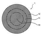
- the optical fiber core 1 according to the present invention has at least two coating layers (a primary layer 11 and a secondary layer 12) that cover the optical fiber 10 around the optical fiber 10.
- FIG. 1 is a cross-sectional view showing an example of the structure of the optical fiber 1.
- 1 indicates an optical fiber core
- 10 indicates an optical fiber
- 11 indicates a primary layer (primary coating layer)
- 12 indicates a secondary layer (secondary coating layer).
- a primary layer (primary coating layer) 11 is formed around the optical fiber 10
- a secondary layer (secondary coating layer) 12 is formed around the primary layer 11. Since the transmission loss of the optical fiber 10 increases due to various external stresses and microbends generated by the external stress, it is necessary to protect the optical fiber 10 from such external stresses.
- a coating a coating having a two-layer structure of a primary layer 11 and a secondary layer 12 is applied.
- the optical fiber 10 such as a glass optical fiber is not particularly limited, but in the present invention, a BI (Bend Insensitive) which has a large effective core area A eff (described later in detail) of the optical fiber is large.
- An optical fiber 10 having a high microbend sensitivity, such as a fiber, can be preferably used.
- the primary layer 11 is an inner layer that is in contact with quartz glass constituting the glass optical fiber, and generally, a soft resin having a relatively small elastic modulus is used.
- the outer layer 11 is generally covered with a secondary layer 12 using a hard resin having a relatively large elastic modulus.
- the constituent material of the primary layer 11 and the secondary layer 12 is an ultraviolet curable resin, for example, an oligomer, a diluting monomer, a photoinitiator, a silane coupling agent, a sensitizer, a lubricant, etc.
- Components can be preferably used (additives are not limited to these, and conventionally known additives used for ultraviolet curable resins and the like can be widely used).
- conventionally known materials such as polyether urethane acrylate, epoxy acrylate, polyester acrylate, and silicone acrylate can be used as the oligomer.
- the diluting monomer a monofunctional monomer or a polyfunctional monomer can be used as the diluting monomer.
- the coating thickness of the primary layer 11 is P ( ⁇ m)
- the coating thickness of the secondary layer 12 is S ( ⁇ m)
- the thermal expansion coefficient of the primary layer 11 is ⁇ P (/ K)
- the elastic modulus (primary elastic modulus) of the primary layer 11 is P ISM (MPa)
- the elastic modulus (secondary elastic modulus) of the secondary layer 12 is S ISM (MPa)
- the relationship of the following formulas (I) and (II) is established.
- the equation (I) is obtained by multiplying the thermal expansion coefficient ⁇ P of the primary layer 11 by the elastic modulus PISM of the primary layer 11 and serves as an index of the degree of freedom (movability) of the primary layer 11 ( , And the unit is MPa / K, but is not particularly listed in the formula (I).) If the degree of freedom obtained by the formula (I) is large and the primary layer 11 is easily moved inside the optical fiber core 1 (between the optical fiber 10 and the secondary layer 12), a fine Even when bending occurs, fine bending can be reduced by the primary layer 11. As a result, it is difficult to transmit the fine bending behavior to the optical fiber 10, so that transmission loss (microbend loss) can be suppressed.
- the degree of freedom in the present invention, by setting the degree of freedom to be equal to or more than 600 MPa / K ( ⁇ 600 MPa / K) as shown in the formula (I), the mobility of the primary layer 11 becomes appropriate and the transmission loss is suppressed. be able to.
- the degree of freedom when the degree of freedom is smaller than 600 MPa / K, the primary layer 11 becomes difficult to move, and when the optical fiber core 1 is finely bent, it is difficult for the primary layer 11 to reduce the fine bending. , Transmission loss increases.
- the degree of freedom represented by the formula (I) is preferably from 600 to 7500 MPa / K.
- equation (II) is obtained by multiplying the ratio of the coating thickness (S / P) with respect to the primary layer by the ratio of the elastic modulus (S ISM / P ISM ), and shows the rigidity of the secondary layer 12. Is shown.
- the degree of freedom (movability) of the primary layer 11 is as described above, when the rigidity of the secondary layer 12 determined by the formula (II) is relatively large, the primary layer 11 serving as an inner layer thereof is used.
- the rigidity of the secondary layer 12 represented by the formula (II) needs to be suppressed to a certain level.
- the rigidity of the secondary layer 12 is set to 1000 or less ( ⁇ 1000) as in the formula (II), so that the mobility of the internal primary layer 11 is appropriately maintained. Therefore, stress can be released to the secondary layer 12 instead of the optical fiber 10, and transmission loss can be suppressed.
- the rigidity exceeds 1000, it becomes difficult to bend the secondary layer 12, so that the primary layer 11 may be difficult to move. Therefore, when a fine bend occurs in the optical fiber 1, it is difficult to reduce the fine bend by the primary layer 11, and the transmission loss increases.
- the rigidity of the secondary layer 12 represented by the formula (II) is preferably 25 to 1000.
- the relationship between the degree of freedom of the primary layer 11 and the transmission loss (microbend loss) determined by the formula (I) is considered to be such that if the degree of freedom is large, the primary layer 11 moves more easily, and the transmission loss becomes smaller.
- the secondary layer represented by the equation (II) In the range of the stiffness of the secondary layer 12 on the horizontal axis and the degree of freedom of the primary layer 11 represented by the formula (I) on the vertical axis, the degree of freedom of the primary layer 11 generally decreases as the rigidity of the secondary layer 12 increases. There is a tendency.
- the standard of the loss level of the transmission loss at the wavelength of 1550 nm determined by the difference in the effective core area A eff (described later) (1.0 dB / km or less, or 0.1 dB / km or less, which will be described later in detail.)
- the degree of freedom of the primary layer 11 is determined based on the relationship between the degree of freedom of the primary layer 11 and the transmission loss.
- the stiffness of the secondary layer 12 selected and thereby selected is selected as the range described above.
- the thermal expansion coefficient ⁇ P of the primary layer 11 is preferably set to 250 to 2500 / K for the reason that the parameter of the formula (I) is provided.
- the thermal expansion coefficient of the primary layer 11 may be measured, for example, by the method described in the following [Example].
- the elastic modulus (primary modulus) P ISM primary layer 11 for having a parameter represented by the formula (I) and formula (II) is preferably set to 0.2 ⁇ 3.0 MPa However, the range is not particularly limited. In general, the higher the elastic modulus, the lower the thermal expansion coefficient, and it is preferable to determine the elastic modulus PISM of the primary layer 11 in consideration of the balance between the two.
- the elastic modulus of the secondary layer 12 to comprise a parameter of the formula (II) (secondary modulus) S ISM is preferably set to 2000MPa or less ( ⁇ 2000MPa).
- the rigidity of the secondary layer 12 can be set to an appropriate range. It is particularly preferable that the elastic modulus of the secondary layer 12 be 500 to 2000 MPa.
- the elastic modulus of each of the primary layer 11 and the secondary layer 12 may be measured, for example, by the method described in the following [Example].
- the elastic modulus of the primary layer 11 corresponds to a so-called in-situ modulus (ISM), and the elastic modulus of the secondary layer 12 corresponds to a so-called 2.5% secant modulus (Secant Modulus).
- the effective core area (effective core area) A eff of the optical fiber 10 is preferably larger than 100 ⁇ m 2 (> 100 ⁇ m 2 ).
- a eff is an index of the micro-bend sensitivity, and a larger value indicates a higher micro-bend sensitivity (in general, it is said that if A eff > 100 ⁇ m 2 , the micro-bend sensitivity is higher). Therefore, when A eff is larger than 100 ⁇ m 2 , the optical fiber 10 has high microbend sensitivity, and the present invention can cope with such.
- the effective core area (effective core area) A eff is 130 ⁇ m 2 or more ( ⁇ 130 ⁇ m 2 ).
- the effective core area (effective core area) A eff is represented by the formula of (MFD) 2 ⁇ ⁇ ⁇ k / 4 (where MFD is a mode field diameter ( ⁇ m) and k is a constant. For example, it is described in C-3-76 and C-3-77 of the 1999 IEICE Electronics Society Conference Proceedings.
- transmission loss can be suppressed even when an optical fiber having high microbend sensitivity is used.
- transmission loss microwave-end loss
- an optical fiber 10 having an effective core area A eff described later that is larger than 100 ⁇ m 2 that is, an optical fiber 10 having a high microbend sensitivity.
- the loss level of the transmission loss at a wavelength of 1550 nm can be set to 1.0 dB / km or less, and the optical fiber 10 having an effective core area A eff of 100 ⁇ m 2 or less is used. In such a case, the loss level of the transmission loss can be set to 0.1 dB / km or less.
- the coating thickness P of the primary layer 11 is preferably 10 to 60 ⁇ m
- the coating thickness S of the secondary layer 12 is preferably 10 to 60 ⁇ m.
- the thickness of each layer is not limited to these values, and can be arbitrarily changed.
- the ratio (S / P) is preferably less than 1 ( ⁇ 1).
- the ratio is less than 1 (that is, the primary layer 11 is thicker than the secondary layer 12)
- the secondary layer 12 has relatively flexibility, which leads to the primary layer 11 being easy to move, and efficiently suppressing transmission loss. I can plan well.
- the adjustment of the elastic modulus of the primary layer 11 and the secondary layer 12 and the coefficient of thermal expansion of the primary layer 11 are performed, for example, by adjusting the components such as the ultraviolet curing resin constituting the primary layer 11 and the secondary layer 12 and the manufacturing conditions of these layers. It can be implemented by adjusting the above.
- the types, molecular weights and contents of oligomers, the types and addition amounts of diluent monomers, and the types and contents of other components, irradiation intensity, etc. in the ultraviolet curable resin or the like constituting the primary layer 11 and the secondary layer 12 The elastic modulus and the like of the primary layer 11 and the secondary layer 12 can be adjusted depending on the conditions of the ultraviolet curing.
- the elastic modulus can be increased by reducing the molecular weight of the oligomer or increasing the content or functional group of the diluent monomer to be added. Therefore, these may be adjusted using these parameters.
- the crosslink density increases and the shrinkage increases. Therefore, it is preferable that the adjustment is performed in consideration of the balance.
- the optical fiber core 1 for example, first, a preform containing quartz glass as a main component is heated and melted by a drawing furnace (not shown) to obtain an optical fiber made of quartz glass (glass optical fiber 10).
- a liquid UV curable resin is applied to the glass optical fiber 10 using a coating die, and subsequently, the applied UV curable resin is irradiated with ultraviolet light by an unillustrated ultraviolet irradiation device (UV irradiation device). Allow the components to cure.
- UV irradiation device an unillustrated ultraviolet irradiation device
- the optical fiber core 1 in which the glass optical fiber 10 is covered with the primary layer 11 and the secondary layer 12 is manufactured.
- the outer periphery of the glass optical fiber 10 is immediately coated with an ultraviolet curable resin to form the primary layer 11 and the secondary layer 12, so that the strength of the obtained optical fiber core wire 1 can be prevented from lowering.
- the type of the UV curable resin, the UV irradiation intensity during the curing process, and the like are set so that the thermal expansion coefficient and the elastic modulus of the primary layer 11 and the elastic modulus of the secondary layer 12 fall within predetermined ranges. It is preferable to control appropriately.
- the degree of freedom of the primary layer 11 shown in the formula (I) and the rigidity of the secondary layer 12 shown in the formula (II) are in the specific ranges.
- an optical fiber core cable 1 capable of suppressing transmission loss even when an optical fiber 10 having a large effective core area A eff of an optical fiber and a high microbend sensitivity such as a BI fiber is used.
- the present invention can be widely used as an optical fiber core 1 constituting an optical fiber tape core or an optical fiber core 1 housed in an optical fiber cable.
- the optical fiber cable configured by including the optical fiber core 1 according to the present invention enjoys the effects of the optical fiber core 1 described above.
- the present invention provides an optical fiber core capable of suppressing transmission loss even when using an optical fiber 10 having a large effective core area A eff of an optical fiber and a high microbend sensitivity such as a BI fiber. 1 is provided.
- the configuration of the optical fiber cable may be a conventionally known optical fiber cable such as a configuration in which the optical fiber core wire 1 according to the present invention is provided and the outer periphery thereof is covered with a sheath (sheath).
- the configuration is not particularly limited.
- the configuration is arbitrary, such as the configuration of an optical fiber cable or the like covered by (2). Therefore, a conventionally known configuration of an optical fiber cable including a configuration other than the above-described configuration can be adopted.
- a so-called optical fiber drop cable configuration in which a pair of notches formed in the longitudinal direction are formed on both sides of the optical fiber cable and a support portion having a built-in support wire is arranged as necessary. I do not care.
- the configuration of the optical fiber cable is not limited to the above-described configuration.
- the type and thickness of the material constituting the outer sheath (sheath), the number and size of the optical fiber core wires 1, and the type of the tension member , Number, size, etc. can be freely selected.
- the outer diameter and cross-sectional shape of the optical fiber cable, the shape and size of the notch, the presence or absence of the notch, and the like can be freely selected.
- the configuration of the optical fiber core wire 1 has been described by showing a configuration in which the primary layer 11 is formed around the optical fiber 10 and the secondary layer 12 is formed around the primary layer 11 in this order.
- a colored layer 13 that is colored around the secondary layer 12 may be formed (referred to as an optical fiber colored core 1).
- FIG. 2 is a cross-sectional view showing another example of the structure of the optical fiber 1.
- the primary layer 11 and the secondary layer 12 described above are used as constituent materials of the colored layer 13. It is preferable to use components such as oligomers, diluting monomers, photoinitiators, silane coupling agents, sensitizers, pigments, lubricants, and other various additives described above, which are the ultraviolet curable resins listed as components to be used. Can be.
- the secondary layer 12 may be colored so as to be the outermost layer of the optical fiber 1 as the colored secondary layer 12.
- the coloring secondary layer 12 can be formed by adding a coloring material in which a pigment, a lubricant, or the like is mixed to the secondary layer 12.
- the content of the coloring material in the colored secondary layer 12 may be appropriately determined depending on the content of the pigment contained in the coloring material, the type of another component such as an ultraviolet curable resin, and the like.
- specific structures, shapes, and the like when the present invention is implemented may be other structures and the like as long as the object of the present invention can be achieved.
- Fiber optic core manufacturing The fiber effective cross-sectional area A eff ( ⁇ m 2 ), primary layer coating thickness P ( ⁇ m), and secondary layer coating thickness S ( ⁇ m) shown in Table 1 are considered to have high microbend sensitivity as an optical fiber.
- three types of optical fibers including optical fibers (Examples 1 to 6 and Comparative Example 1 in which A eff is larger than 100 ⁇ m 2 )
- a primary layer and a secondary layer are formed around a glass optical fiber made of quartz glass.
- the coating thickness (P ( ⁇ m), S ( ⁇ m)) shown in Table 1 was obtained, and an optical fiber core having the configuration shown in FIG. 1 was manufactured.
- the primary layer and the secondary layer were manufactured using a commercially available ultraviolet curable resin (oligomer, diluent monomer, photoinitiator, silane coupling agent, sensitizer, lubricant, etc.).
- the adjustment of the elastic modulus of the primary layer and the secondary layer and the thermal expansion coefficient of the primary layer, which are the parameters, are performed so that the respective types become the values shown in Table 1 so that the type of the ultraviolet curing resin and the ultraviolet irradiation conditions (for example, The weight-average molecular weight and content of oligomers and the like constituting the UV-curable resin, the type and number of functional groups in the dilutable monomer, the content, the type of photoinitiator, the intensity of UV irradiation, etc. It carried out by changing each.
- Example 1 to 4 and Comparative Example 1 the primary layer and the secondary layer use the same material, and the coating thickness of the primary layer and the secondary layer and the manufacturing conditions (ultraviolet irradiation intensity and the like) are used.
- the manufacturing conditions were the same in the following.).
- Example 5 and Example 6 were manufactured by using the same material for the primary layer, changing the material and coating thickness of the secondary layer, and changing the manufacturing conditions.
- Example 7 and Comparative Example 2 the materials and coating thicknesses of the primary layer and the secondary layer were changed, and the manufacturing conditions were common.
- Elastic modulus of primary layer The elastic modulus (In-situ Modulus: ISM) of the primary layer was measured by the following method. First, after stripping off a few mm of the primary and secondary layers in the middle of the optical fiber using a commercially available stripper, one end of the optical fiber on which the coating is formed is fixed on a slide glass with an adhesive, and the coating is applied. A load F is applied to the other end of the optical fiber in which is formed. In this state, the displacement ⁇ of the primary layer at the boundary between the portion where the coating was peeled off and the portion where the coating was formed was read with a microscope.
- ISM In-situ Modulus
- PISM elastic modulus
- F / ⁇ is the slope shown by the graph of the displacement ( ⁇ ) with respect to the load (F)
- l is the sample length (for example, 10 mm)
- D P / DG is the primary It is the ratio of the outer diameter of the layer (D P ) ( ⁇ m) to the outer diameter of the optical fiber (D G ) ( ⁇ m).
- the outer diameter of the primary layer and the outer diameter of the optical fiber were measured by observing a cross section of the optical fiber cut by a fiber cutter with a microscope (see also (3) described later).
- Thermal expansion coefficient of primary layer The method of calculating the thermal expansion coefficient of the primary layer (volume thermal expansion coefficient from -50 ° C to 25 ° C) will be described below (specifically, Furukawa Electric Time Report No. 122 (September 2008), “Optical Fiber Measurement method of thermal strain and thermal stress generated in coating layer ”and“ 4-3 ”. An outline is shown below.)
- a sample in which a primary layer and a secondary layer are coated on a glass optical fiber hereinafter, referred to as a “fiber sample”
- the other is a coating layer obtained by removing a glass optical fiber from an optical fiber core.
- tube-coated sample tube sample
- the thermal expansion coefficient was measured in the longitudinal direction and the outer diameter direction using a commercially available TMA thermomechanical analysis (Mettler Toledo TMA 40). The measurement conditions were: applied load: 0 load, temperature range: cooling temperature at -25 ° C to -100 ° C was -10 ° C / min, holding time at -100 ° C was 10 minutes, and heating rate at -100 ° C to 100 ° C was 10 ° C./min.
- each linear expansion coefficient is set at ⁇ 50 ° C. near the glass transition temperature of the primary layer.
- the coefficient of expansion was determined from the slope of the temperature range from -50 ° C. to 25 ° C., which is a range in which the measurement result changes linearly.
- the coefficient of thermal expansion of the primary layer and the secondary layer depends on the tensile mode (longitudinal direction) of the tube-coated sample (tube sample) and the compression mode (outside It was estimated from the linear expansion coefficient in the radial direction).
- thermal expansion coefficient of the primary layer volume thermal expansion coefficient in the range of ⁇ 50 ° C. to 25 ° C., hereinafter simply referred to as “thermal expansion coefficient” including the secondary layer
- thermal expansion coefficient including the secondary layer
- the thermal expansion of the secondary layer is calculated.
- the coefficients were calculated.
- the glass transition temperature of the primary layer is as low as about ⁇ 50 ° C.
- the primary layer of the tube-coated sample is in a rubbery state, and has a significantly lower elastic modulus than the secondary layer. Can freely expand and contract.
- the coefficient of thermal expansion of the secondary layer is obtained by adding the coefficient of linear expansion in the longitudinal direction to twice the coefficient of linear expansion in the outer diameter direction, and the coefficient of thermal expansion of the secondary layer is obtained by the following equation (Y).
- ⁇ S is the thermal expansion coefficient (volume thermal expansion coefficient) (/ K) of the secondary layer
- ⁇ SL is the linear expansion coefficient (/ K) in the longitudinal direction of the secondary layer
- ⁇ SR is the radial expansion coefficient of the secondary layer.
- the thermal expansion of the coating layer is restrained by the optical fiber because the secondary layer cannot freely expand and contract because the primary layer is bonded to the optical fiber.
- the thermal expansion coefficient of the quartz glass constituting the optical fiber is significantly smaller than that of the coating layer, the thermal expansion can be ignored. From the above, the coefficient of thermal expansion of the primary layer (the coefficient of volume thermal expansion at ⁇ 50 ° C. to 25 ° C.) was calculated from the following equation (Z).
- ⁇ P is the thermal expansion coefficient (volume thermal expansion coefficient) of the primary layer (/ K)
- ⁇ S is the thermal expansion coefficient (volume thermal expansion coefficient) of the secondary layer (/ K) (equation ( calculated by Y).)
- D G is the outer diameter (about 125 ⁇ m optical fiber)
- an outer diameter of D P is the primary layer ([mu] m)
- D S is the outer diameter of which indicates the outer diameter of the secondary layer ([mu] m), respectively (primary layer, "the outer diameter of the optical fiber + (coating thickness ⁇ 2 primary layer)", the outer diameter of the secondary layer, " Outer diameter of primary layer + (coating thickness of secondary layer ⁇ 2) ”.
- Transmission loss (microbend loss): The transmission loss was measured, and the microbend resistance was evaluated.
- IEC TR62221 fixed drum method
- a transmission loss measuring method was used as a transmission loss measuring method. Specifically, first, a mesh of # 150 was wound around a drum having a diameter of 400 mm, and an optical fiber core of 850 m was wound thereon in a single layer with a tension of 1 N, and the transmission loss after standing for 24 hours was measured. Then, a value obtained by subtracting the transmission loss in the bundle state (the state where the drum is not wound around the drum) from the obtained transmission loss was defined as a transmission loss (microbend loss).
- the transmission loss is measured by measuring the transmission loss at a wavelength of 1550 nm (1.55 ⁇ m). At a wavelength of 1550 nm, the transmission loss due to microbending (microbend loss) is determined by the effective core area A eff of the optical fiber. 1 to 4 and Comparative Example 1 in which the effective core area of the optical fiber is 150 ⁇ m 2 , and Examples 5 and 6 in which the effective core area A eff of the optical fiber is 130 ⁇ m 2 are 1.0 dB / km or less.
- Example 7 (A value of 1.0 dB / km or less was passed, and a value exceeding 1.0 dB / km was rejected.) Further, in Example 7 and Comparative Example 2 in which the effective core area A eff of the optical fiber is 85 ⁇ m 2 , the effective core area is 0.1 dB / km or less (pass 0.1 dB / km or less, 0.1 dB / km or less). If it exceeded, it was rejected.)
- the optical fiber cores of Examples 1 to 7 having the formulas (I) and (II) were obtained when an optical fiber having high microbend sensitivity was used as the optical fiber.
- the transmission loss microwave end loss
- the transmission loss in the seventh embodiment is 0.1 dB / km or less. In this case, transmission loss could be suppressed.
- the transmission loss of the comparative example 1 exceeds 1.0 dB / km, and the comparative example 2 has a transmission loss of 0 dB / km. 0.1 dB / km, and transmission loss could not be suppressed.
- the present invention is not limited to this, and can be applied to an optical fiber having an outer diameter of 80 to 125 ⁇ m, for example.
- the present invention can be effectively used as a means for providing an optical fiber core having an optical fiber having a high microbend sensitivity and an optical fiber cable having such an optical fiber, and industrial applicability is high. high.
- optical fiber core optical fiber colored core
- optical fiber 11 primary layer (primary coating layer)
- Secondary layer secondary coating layer 13 Coloring layer
Priority Applications (5)
| Application Number | Priority Date | Filing Date | Title |
|---|---|---|---|
| EP19860490.2A EP3851890A4 (en) | 2018-09-13 | 2019-09-11 | FIBER OPTIC CORE WIRE AND FIBER OPTIC CABLE |
| BR112021004328-4A BR112021004328A2 (pt) | 2018-09-13 | 2019-09-11 | Anticorpos antifamília com similaridade de sequência 19, membro a5 e método de usar os mesmos |
| CN201980058384.3A CN112654908B (zh) | 2018-09-13 | 2019-09-11 | 光纤芯线和光纤线缆 |
| JP2020546047A JP7370995B2 (ja) | 2018-09-13 | 2019-09-11 | 光ファイバ心線及び光ファイバケーブル |
| US17/200,458 US11435518B2 (en) | 2018-09-13 | 2021-03-12 | Coated optical fiber and optical fiber cable |
Applications Claiming Priority (2)
| Application Number | Priority Date | Filing Date | Title |
|---|---|---|---|
| JP2018171881 | 2018-09-13 | ||
| JP2018-171881 | 2018-09-13 |
Related Child Applications (1)
| Application Number | Title | Priority Date | Filing Date |
|---|---|---|---|
| US17/200,458 Continuation US11435518B2 (en) | 2018-09-13 | 2021-03-12 | Coated optical fiber and optical fiber cable |
Publications (1)
| Publication Number | Publication Date |
|---|---|
| WO2020054753A1 true WO2020054753A1 (ja) | 2020-03-19 |
Family
ID=69776822
Family Applications (1)
| Application Number | Title | Priority Date | Filing Date |
|---|---|---|---|
| PCT/JP2019/035634 WO2020054753A1 (ja) | 2018-09-13 | 2019-09-11 | 光ファイバ心線及び光ファイバケーブル |
Country Status (6)
| Country | Link |
|---|---|
| US (1) | US11435518B2 (zh) |
| EP (1) | EP3851890A4 (zh) |
| JP (1) | JP7370995B2 (zh) |
| CN (1) | CN112654908B (zh) |
| BR (1) | BR112021004328A2 (zh) |
| WO (1) | WO2020054753A1 (zh) |
Cited By (2)
| Publication number | Priority date | Publication date | Assignee | Title |
|---|---|---|---|---|
| WO2021187514A1 (ja) * | 2020-03-18 | 2021-09-23 | 古河電気工業株式会社 | 光ファイバ心線、光ファイバケーブル及び光ファイバテープ心線 |
| WO2022158496A1 (ja) * | 2021-01-21 | 2022-07-28 | 古河電気工業株式会社 | 光ファイバ、光ファイバテープ心線および光ファイバケーブル |
Citations (5)
| Publication number | Priority date | Publication date | Assignee | Title |
|---|---|---|---|---|
| JPH0611634A (ja) | 1992-06-25 | 1994-01-21 | Furukawa Electric Co Ltd:The | 細径光ファイバ心線 |
| WO2002066390A1 (en) * | 2001-02-20 | 2002-08-29 | Sumitomo Electric Industries, Ltd. | Coated optical fiber, optical fiber tape core using it and optical fiber unit |
| JP2004059420A (ja) * | 2002-06-07 | 2004-02-26 | Fujikura Ltd | 一次被覆層及び二次被覆層を備えた光ファイバ、光ファイバケーブル、及びその製造方法 |
| JP2014530374A (ja) * | 2011-09-16 | 2014-11-17 | コーニング インコーポレイテッド | モード分割多重化用数モード光ファイバ |
| US20170153389A1 (en) * | 2015-11-30 | 2017-06-01 | Corning Incorporated | Flame-retardant optical fiber coating |
Family Cites Families (10)
| Publication number | Priority date | Publication date | Assignee | Title |
|---|---|---|---|---|
| NL8303252A (nl) * | 1983-09-22 | 1985-04-16 | Philips Nv | Optische glasvezel voorzien van een eerste en een tweede bedekking. |
| US6804442B1 (en) * | 2002-06-07 | 2004-10-12 | Fujikura Ltd. | Optical fiber and optical fiber cable having a first jacket layer and a second jacket layer and a coefficient of thermal expansion selecting method |
| US7542644B2 (en) | 2003-02-20 | 2009-06-02 | Sumitomo Electric Industries, Ltd. | Coated optical fiber and coated optical fiber with connector |
| JP3912531B2 (ja) * | 2003-02-20 | 2007-05-09 | 住友電気工業株式会社 | 被覆光ファイバ心線 |
| JP2007322893A (ja) * | 2006-06-02 | 2007-12-13 | Furukawa Electric Co Ltd:The | 光ファイバ心線とその評価方法 |
| JPWO2008012926A1 (ja) | 2006-07-28 | 2009-12-17 | 古河電気工業株式会社 | 光ファイバ |
| JP5041450B2 (ja) * | 2010-11-24 | 2012-10-03 | 古河電気工業株式会社 | 光ファイバ着色心線 |
| JP5294357B2 (ja) * | 2012-02-15 | 2013-09-18 | 古河電気工業株式会社 | 光ファイバ着色心線、光ファイバテープ心線及び光ファイバケーブル |
| JP6459215B2 (ja) | 2014-05-14 | 2019-01-30 | 住友電気工業株式会社 | 光ファイバ及び光ファイバの評価方法 |
| CN110383130B (zh) | 2017-03-03 | 2021-06-22 | 住友电气工业株式会社 | 光纤 |
-
2019
- 2019-09-11 BR BR112021004328-4A patent/BR112021004328A2/pt unknown
- 2019-09-11 EP EP19860490.2A patent/EP3851890A4/en active Pending
- 2019-09-11 CN CN201980058384.3A patent/CN112654908B/zh active Active
- 2019-09-11 WO PCT/JP2019/035634 patent/WO2020054753A1/ja unknown
- 2019-09-11 JP JP2020546047A patent/JP7370995B2/ja active Active
-
2021
- 2021-03-12 US US17/200,458 patent/US11435518B2/en active Active
Patent Citations (5)
| Publication number | Priority date | Publication date | Assignee | Title |
|---|---|---|---|---|
| JPH0611634A (ja) | 1992-06-25 | 1994-01-21 | Furukawa Electric Co Ltd:The | 細径光ファイバ心線 |
| WO2002066390A1 (en) * | 2001-02-20 | 2002-08-29 | Sumitomo Electric Industries, Ltd. | Coated optical fiber, optical fiber tape core using it and optical fiber unit |
| JP2004059420A (ja) * | 2002-06-07 | 2004-02-26 | Fujikura Ltd | 一次被覆層及び二次被覆層を備えた光ファイバ、光ファイバケーブル、及びその製造方法 |
| JP2014530374A (ja) * | 2011-09-16 | 2014-11-17 | コーニング インコーポレイテッド | モード分割多重化用数モード光ファイバ |
| US20170153389A1 (en) * | 2015-11-30 | 2017-06-01 | Corning Incorporated | Flame-retardant optical fiber coating |
Cited By (3)
| Publication number | Priority date | Publication date | Assignee | Title |
|---|---|---|---|---|
| WO2021187514A1 (ja) * | 2020-03-18 | 2021-09-23 | 古河電気工業株式会社 | 光ファイバ心線、光ファイバケーブル及び光ファイバテープ心線 |
| US11914205B2 (en) | 2020-03-18 | 2024-02-27 | Furukawa Electric Co., Ltd. | Coated optical fiber, optical fiber cable, and coated optical fiber ribbon |
| WO2022158496A1 (ja) * | 2021-01-21 | 2022-07-28 | 古河電気工業株式会社 | 光ファイバ、光ファイバテープ心線および光ファイバケーブル |
Also Published As
| Publication number | Publication date |
|---|---|
| US20210199883A1 (en) | 2021-07-01 |
| BR112021004328A2 (pt) | 2021-09-21 |
| EP3851890A4 (en) | 2022-06-08 |
| CN112654908B (zh) | 2023-03-24 |
| EP3851890A1 (en) | 2021-07-21 |
| CN112654908A (zh) | 2021-04-13 |
| JPWO2020054753A1 (ja) | 2021-08-30 |
| JP7370995B2 (ja) | 2023-10-30 |
| US11435518B2 (en) | 2022-09-06 |
Similar Documents
| Publication | Publication Date | Title |
|---|---|---|
| US8467650B2 (en) | High-fiber-density optical-fiber cable | |
| US8041168B2 (en) | Reduced-diameter ribbon cables with high-performance optical fiber | |
| US8265442B2 (en) | Microbend-resistant optical fiber | |
| US8145026B2 (en) | Reduced-size flat drop cable | |
| JP4134724B2 (ja) | 被覆光ファイバ、これを用いた光ファイバテープ心線及び光ファイバユニット | |
| US8639077B2 (en) | Colored coated optical fiber | |
| US9291769B2 (en) | Colored optical fiber, optical fiber ribbon and optical fiber cable, using colored optical fiber | |
| WO2008012926A1 (en) | Optical fiber | |
| JP6273847B2 (ja) | 光ファイバおよび光ケーブル | |
| JP5027318B2 (ja) | 光ファイバ心線 | |
| KR20170068482A (ko) | 광섬유 심선 및 광섬유 테이프 심선 | |
| DE60032944T2 (de) | Sekundärbeschichtung für lichtleitfasern | |
| JP2007322893A (ja) | 光ファイバ心線とその評価方法 | |
| US11435518B2 (en) | Coated optical fiber and optical fiber cable | |
| JP2016210651A (ja) | 光ファイバ心線 | |
| JP5787927B2 (ja) | オーバーコート心線及び当該オーバーコート心線を備えた光ファイバケーブル | |
| JP5983584B2 (ja) | 光ファイバ心線 | |
| WO2021187514A1 (ja) | 光ファイバ心線、光ファイバケーブル及び光ファイバテープ心線 | |
| JP2004107184A (ja) | 被覆光ファイバ | |
| JPH11194071A (ja) | 光ファイバ心線及びその摩擦係数の測定方法 | |
| JP2001240433A (ja) | 被覆光ファイバ | |
| EP3316009A1 (en) | Optical fiber for indoor applications | |
| WO2024035829A1 (en) | Optical fiber having thin coating diameter without increased microbend sensitivity | |
| JP2001100067A (ja) | 光ファイバテープ心線及び光ファイバケーブル | |
| JP2000284155A (ja) | 光ファイバ |
Legal Events
| Date | Code | Title | Description |
|---|---|---|---|
| 121 | Ep: the epo has been informed by wipo that ep was designated in this application |
Ref document number: 19860490 Country of ref document: EP Kind code of ref document: A1 |
|
| ENP | Entry into the national phase |
Ref document number: 2020546047 Country of ref document: JP Kind code of ref document: A |
|
| NENP | Non-entry into the national phase |
Ref country code: DE |
|
| REG | Reference to national code |
Ref country code: BR Ref legal event code: B01A Ref document number: 112021004328 Country of ref document: BR |
|
| ENP | Entry into the national phase |
Ref document number: 2019860490 Country of ref document: EP Effective date: 20210413 |
|
| REG | Reference to national code |
Ref country code: BR Ref legal event code: B01E Ref document number: 112021004328 Country of ref document: BR Free format text: APRESENTE TRADUCAO SIMPLES DA CERTIDAO DE DEPOSITO DA PRIORIDADE NO PAIS DE ORIGEM OU DECLARACAO ASSINADA, AMBAS CONTENDO TODOS OS DADOS IDENTIFICADORES DA PRIORIDADE, CONFORME ART. 16, 2O, DA LPI. |
|
| ENP | Entry into the national phase |
Ref document number: 112021004328 Country of ref document: BR Kind code of ref document: A2 Effective date: 20210308 |