WO2020054615A1 - Electrode for secondary battery and secondary battery - Google Patents
Electrode for secondary battery and secondary battery Download PDFInfo
- Publication number
- WO2020054615A1 WO2020054615A1 PCT/JP2019/035201 JP2019035201W WO2020054615A1 WO 2020054615 A1 WO2020054615 A1 WO 2020054615A1 JP 2019035201 W JP2019035201 W JP 2019035201W WO 2020054615 A1 WO2020054615 A1 WO 2020054615A1
- Authority
- WO
- WIPO (PCT)
- Prior art keywords
- secondary battery
- electrode
- graphene
- less
- mass
- Prior art date
Links
Images


Classifications
-
- H—ELECTRICITY
- H01—ELECTRIC ELEMENTS
- H01M—PROCESSES OR MEANS, e.g. BATTERIES, FOR THE DIRECT CONVERSION OF CHEMICAL ENERGY INTO ELECTRICAL ENERGY
- H01M4/00—Electrodes
- H01M4/02—Electrodes composed of, or comprising, active material
- H01M4/62—Selection of inactive substances as ingredients for active masses, e.g. binders, fillers
- H01M4/624—Electric conductive fillers
- H01M4/625—Carbon or graphite
-
- C—CHEMISTRY; METALLURGY
- C01—INORGANIC CHEMISTRY
- C01B—NON-METALLIC ELEMENTS; COMPOUNDS THEREOF; METALLOIDS OR COMPOUNDS THEREOF NOT COVERED BY SUBCLASS C01C
- C01B32/00—Carbon; Compounds thereof
- C01B32/15—Nano-sized carbon materials
- C01B32/182—Graphene
- C01B32/184—Preparation
- C01B32/19—Preparation by exfoliation
- C01B32/192—Preparation by exfoliation starting from graphitic oxides
-
- C—CHEMISTRY; METALLURGY
- C01—INORGANIC CHEMISTRY
- C01B—NON-METALLIC ELEMENTS; COMPOUNDS THEREOF; METALLOIDS OR COMPOUNDS THEREOF NOT COVERED BY SUBCLASS C01C
- C01B32/00—Carbon; Compounds thereof
- C01B32/15—Nano-sized carbon materials
- C01B32/182—Graphene
- C01B32/194—After-treatment
-
- H—ELECTRICITY
- H01—ELECTRIC ELEMENTS
- H01M—PROCESSES OR MEANS, e.g. BATTERIES, FOR THE DIRECT CONVERSION OF CHEMICAL ENERGY INTO ELECTRICAL ENERGY
- H01M10/00—Secondary cells; Manufacture thereof
- H01M10/05—Accumulators with non-aqueous electrolyte
- H01M10/052—Li-accumulators
- H01M10/0525—Rocking-chair batteries, i.e. batteries with lithium insertion or intercalation in both electrodes; Lithium-ion batteries
-
- H—ELECTRICITY
- H01—ELECTRIC ELEMENTS
- H01M—PROCESSES OR MEANS, e.g. BATTERIES, FOR THE DIRECT CONVERSION OF CHEMICAL ENERGY INTO ELECTRICAL ENERGY
- H01M4/00—Electrodes
- H01M4/02—Electrodes composed of, or comprising, active material
- H01M4/13—Electrodes for accumulators with non-aqueous electrolyte, e.g. for lithium-accumulators; Processes of manufacture thereof
- H01M4/131—Electrodes based on mixed oxides or hydroxides, or on mixtures of oxides or hydroxides, e.g. LiCoOx
-
- H—ELECTRICITY
- H01—ELECTRIC ELEMENTS
- H01M—PROCESSES OR MEANS, e.g. BATTERIES, FOR THE DIRECT CONVERSION OF CHEMICAL ENERGY INTO ELECTRICAL ENERGY
- H01M4/00—Electrodes
- H01M4/02—Electrodes composed of, or comprising, active material
- H01M4/36—Selection of substances as active materials, active masses, active liquids
- H01M4/48—Selection of substances as active materials, active masses, active liquids of inorganic oxides or hydroxides
- H01M4/52—Selection of substances as active materials, active masses, active liquids of inorganic oxides or hydroxides of nickel, cobalt or iron
- H01M4/525—Selection of substances as active materials, active masses, active liquids of inorganic oxides or hydroxides of nickel, cobalt or iron of mixed oxides or hydroxides containing iron, cobalt or nickel for inserting or intercalating light metals, e.g. LiNiO2, LiCoO2 or LiCoOxFy
-
- H—ELECTRICITY
- H01—ELECTRIC ELEMENTS
- H01M—PROCESSES OR MEANS, e.g. BATTERIES, FOR THE DIRECT CONVERSION OF CHEMICAL ENERGY INTO ELECTRICAL ENERGY
- H01M10/00—Secondary cells; Manufacture thereof
- H01M10/05—Accumulators with non-aqueous electrolyte
- H01M10/052—Li-accumulators
-
- H—ELECTRICITY
- H01—ELECTRIC ELEMENTS
- H01M—PROCESSES OR MEANS, e.g. BATTERIES, FOR THE DIRECT CONVERSION OF CHEMICAL ENERGY INTO ELECTRICAL ENERGY
- H01M4/00—Electrodes
- H01M4/02—Electrodes composed of, or comprising, active material
- H01M2004/021—Physical characteristics, e.g. porosity, surface area
-
- H—ELECTRICITY
- H01—ELECTRIC ELEMENTS
- H01M—PROCESSES OR MEANS, e.g. BATTERIES, FOR THE DIRECT CONVERSION OF CHEMICAL ENERGY INTO ELECTRICAL ENERGY
- H01M4/00—Electrodes
- H01M4/02—Electrodes composed of, or comprising, active material
- H01M2004/026—Electrodes composed of, or comprising, active material characterised by the polarity
- H01M2004/028—Positive electrodes
-
- Y—GENERAL TAGGING OF NEW TECHNOLOGICAL DEVELOPMENTS; GENERAL TAGGING OF CROSS-SECTIONAL TECHNOLOGIES SPANNING OVER SEVERAL SECTIONS OF THE IPC; TECHNICAL SUBJECTS COVERED BY FORMER USPC CROSS-REFERENCE ART COLLECTIONS [XRACs] AND DIGESTS
- Y02—TECHNOLOGIES OR APPLICATIONS FOR MITIGATION OR ADAPTATION AGAINST CLIMATE CHANGE
- Y02E—REDUCTION OF GREENHOUSE GAS [GHG] EMISSIONS, RELATED TO ENERGY GENERATION, TRANSMISSION OR DISTRIBUTION
- Y02E60/00—Enabling technologies; Technologies with a potential or indirect contribution to GHG emissions mitigation
- Y02E60/10—Energy storage using batteries
Definitions
- the present invention relates to an electrode for a secondary battery such as a lithium ion battery and an all solid state battery, and a secondary battery.
- secondary batteries such as lithium-ion batteries and all-solid-state batteries for mobile devices such as smartphones and mobile phones, hybrid vehicles, electric vehicles, and home power storage applications have been actively conducted.
- a material having poor electronic conductivity such as a metal oxide is used as an active material of the secondary battery
- a conductive additive such as a carbon material is added in addition to the active material in order to impart electronic conductivity. Electrodes are used.
- One of the major issues of secondary batteries is to improve the life, that is, to maintain the battery capacity when charging and discharging are repeated.
- One of the causes of a decrease in battery capacity due to repeated use is a decrease in electron conductivity. Initially, there is no problem in electron conductivity because the electrodes are tightly packed, but repeated charging and discharging causes the active material to expand and contract, creating voids in the electrodes and decomposing with the electrolyte. The formation of the insulator coating by the product results in an extreme decrease in electronic conductivity, resulting in a reduction in battery capacity. In order to prevent such a decrease in battery capacity, it is considered important to form a conductive network that firmly connects the active materials at the beginning and maintain this network against expansion and contraction of the active material. .
- Patent Document 1 the average particle diameter, the average area, and the aspect ratio of the aggregate of the conductive additive obtained by performing image analysis on a surface photograph of the negative electrode obtained by a scanning electron microscope are described. It has been proposed to improve the conductive network by defining a certain range.
- Patent Literature 2 the size of the aggregate of the conductive auxiliary obtained by analyzing the mapping image of carbon on the electrode cross section, the distribution state, and the resistance of the electrode are defined in a certain range to form a conductive network. Improvements have been proposed.
- a graphene composition containing thiourea having an element ratio of sulfur to carbon of 0.04 or more and 0.12 or less, an electrode active material, and a lithium ion battery electrode containing a binder for example, see Patent Document 3
- the value is 0.05 or more and 0.4 or less
- an electrode for example, see Patent Document 4 in which the weighted average value of the roundness is weighted by the area of the particle has been proposed.
- JP 2012-14838 A JP-A-2015-215947 JP-T-2016-500895 JP, 2018-160418, A
- Patent Document 1 since the carbon material in which the primary particles are aggregated is used, the carbon material is also present in the electrode in an aggregate. If the aggregates are present in a lump larger than a certain range in the electrode, the ratio of the portion where the active material and the conductive additive do not come into contact increases, and the electronic resistance on the active material surface increases, which lowers the output of the battery. I do. In addition, when such a lump exists, the capacity is extremely reduced by repeated use.
- the electrode described in Patent Document 3 can improve output characteristics and life with graphene having high conductivity and high dispersibility, it is difficult to increase the capacity of a secondary battery in recent years. And a short distance conductive network connecting the conductive assistants is still insufficient, and further higher output and longer life are required.
- the electrode described in Patent Document 4 uses a functionalized graphene or carbon nanotube to form a conductive network with low roundness (high aspect ratio), but still has output characteristics and lifetime. Was insufficient.
- An object of the present invention is to provide an electrode for a secondary battery with improved output and life.
- the present invention for solving the above problems, Graphene, a secondary battery electrode having a mixture layer including at least lithium and nickel-containing secondary battery active material particles, A secondary battery electrode in which the average aspect ratio of the conductive material portion in the cross section of the secondary battery electrode specified by the following method is 2.0 or more.
- Method of specifying conductive material part (1) Obtain the spread resistance value of the mixture layer portion by scanning spread resistance microscopy.
- Electrode for secondary battery has a mixture layer containing graphene and active material particles for a secondary battery.
- graphene In the electrode for a secondary battery according to the present invention, graphene, which is thin, has a planar shape, has a large number of conductive paths per unit weight, and easily forms a strong conductive network in the electrode, is used as the conductive additive.
- Graphene is in a narrow sense refers to a 1 thickness sp 2 bonded carbon atoms of the atoms sheet (monolayer graphene), in this specification, including those monolayer graphene has a flaky form laminated Called graphene.
- graphene oxide is also referred to as having a laminated flake shape.
- the thickness of graphene used in the present invention is not particularly limited, but is preferably 100 nm or less, more preferably 50 nm or less, and further preferably 20 nm or less.
- the thickness of the graphene is 100 nm or less, the flexibility is improved and the surface of the graphene is easily contacted with the active material particles for a secondary battery, so that a stronger conductive network can be formed.
- As the thickness of graphene a value obtained as follows is used. First, graphene separated from the mixture layer by a method described later is diluted to 0.002% by mass with N-methylpyrrolidone (NMP), dropped on a glass substrate, and dried.
- NMP N-methylpyrrolidone
- the graphene on the substrate is observed with a laser microscope capable of measuring a three-dimensional shape, and the thickness of each graphene is measured. If the thickness of each graphene varies, the area average is determined. In this way, the thickness is randomly calculated for 50 graphenes, and the average value is defined as the graphene thickness.
- the size of the graphene in the plane direction is not particularly limited, but is preferably 0.5 ⁇ m or more, more preferably 0.7 ⁇ m or more, further preferably 1.0 ⁇ m or more as a lower limit, and preferably 50 ⁇ m or less as an upper limit. , More preferably 10 ⁇ m or less, and even more preferably 5.0 ⁇ m or less.
- the size of the graphene in the plane direction is 0.5 ⁇ m or more, aggregation of the graphene can be suppressed, and the output characteristics and the life can be further improved.
- the size of the graphene in the plane direction is 50 ⁇ m or less, the portion in contact with the active material particles increases, so that the electronic resistance decreases and the output characteristics and the life can be further improved.
- the size of the graphene in the plane direction was determined by observing the graphene separated from the mixture layer by a method described below at a magnification of 1,000 times using a laser microscope and measuring the area S for 100 randomly selected graphenes. And the arithmetic mean of the values obtained by 2 ⁇ (S / ⁇ ) 1/2 can be determined.
- the specific surface area of graphene reflects the thickness of graphene and the degree of exfoliation of graphene. The larger the specific surface area of the graphene, the thinner the graphene, and the higher the exfoliation degree. The larger the specific surface area of graphene, that is, the higher the degree of exfoliation, the easier it is to form a conductive network of the electrode, while the more easily it is agglomerated, the lower the dispersibility tends to be.
- the graphene used in the present invention preferably has a specific surface area measured by a BET measurement method of 80 m 2 / g or more and 250 m 2 / g or less, more preferably 100 m 2 / g or more and 200 m 2 / g or less. preferably, it is more preferably not more than 130m 2 / g or more 180 m 2 / g.
- the BET measurement method is performed by the method described in JIS Z8830: 2013, the measurement method of the amount of adsorbed gas is performed by the carrier gas method, and the analysis of the adsorption data is performed by the one-point method.
- the graphene used in the present invention preferably has an element ratio of oxygen to carbon (O / C ratio) of 0.08 or more and 0.30 or less measured by X-ray photoelectron spectroscopy. If the number of oxygen atoms on the graphene surface is too small, the dispersibility becomes poor.
- the O / C ratio of graphene is more preferably 0.12 or more and 0.20 or less, and still more preferably 0.14 or more and 0.17 or less.
- the O / C ratio of graphene is 0.08 or more, the dispersibility can be improved, and the output characteristics and the life can be further improved.
- the O / C ratio of the graphene is 0.30 or less, the graphene is sufficiently reduced, the conductivity can be further improved by the ⁇ -electron conjugate structure, and the output characteristics can be further improved.
- a surface treatment agent may be added to graphene, but not only the functional group of the graphene itself, but also oxygen atoms derived from the functional group of such a surface treatment agent are included in the “oxygen atoms on the graphene surface”. Shall be. That is, in graphene to which the surface treatment agent has been applied, the O / C ratio of the surface after the surface treatment agent treatment is preferably in the above range.
- X-ray photoelectron spectroscopy soft X-rays are irradiated on the surface of a sample placed in an ultra-high vacuum, and photoelectrons emitted from the surface are detected by an analyzer.
- the photoelectrons are measured by wide scan, and the binding energy value of the bound electrons in the substance is obtained, whereby the element information on the surface of the substance can be obtained. Further, the element ratio can be determined using the peak area ratio.
- the O / C ratio can be controlled by, for example, changing the degree of oxidation of the raw material graphene oxide or changing the amount of the surface treatment agent when a chemical stripping method is used.
- the amount of oxygen can be increased as the amount of the surface treatment agent having an acidic group attached increases.
- the graphene used in the present invention may be subjected to a surface treatment. It is preferable that a surface treatment agent having an affinity for a solvent adheres to the graphene surface, and the dispersibility of the graphene can be improved.
- a surface treatment agent a compound having a phenyl group and / or an amino group is preferable, and examples thereof include 3-chloroaniline, benzylamine, 2-phenylethylamine, 1-naphthylamine, dopamine hydrochloride or a neutralized salt thereof. . Two or more of these may be used.
- fibrous carbon In the secondary battery electrode of the present invention, it is preferable that fibrous carbon is contained as the conductive assistant. In the case where only graphene is included as the conductive additive, in a manufacturing process such as removal of a solvent by drying, a part of the graphene may be aggregated. When fibrous carbon is combined with graphene, fibrous carbon bridges graphene by ⁇ - ⁇ interaction, so that aggregation of graphene and fibrous carbon can be suppressed. In addition, the active material particles are also bridged by the fibrous carbon, and the bridged portion is reinforced by the planar graphene, so that a strong three-dimensional conductive network can be formed over the entire electrode.
- fibrous carbon examples include single-walled carbon nanotubes, double-walled carbon nanotubes, multi-walled carbon nanotubes having three or more layers, and carbon nanotubes such as vapor-grown carbon fibers. Two or more of these may be included.
- vapor grown carbon fiber examples include “VGCF” (registered trademark) (manufactured by Showa Denko KK).
- the fibrous carbon preferably has a shape that is flexible and easily dispersed.
- the outer diameter of the fibrous carbon used in the present invention is preferably from 3.0 nm to 50 nm, more preferably from 5.0 nm to 20 nm.
- the outer diameter of the fibrous carbon is 3.0 nm or more, the bundle generated by the agglomeration by Van der Waals force can be easily unwound, the dispersibility can be improved, and the output characteristics and the life can be further improved.
- the diameter of the fibrous carbon is 50 nm or less, the flexibility is high, and a conductive network between the active material particles and between the conductive additives can be more easily formed.
- the diameter of the fibrous carbon is the fiber diameter (outer diameter) of the fibrous carbon, and the fibrous carbon separated from the mixture layer by the method described below is measured using a field emission scanning microscope (FE-SEM).
- the fibrous carbon can be determined by observing at a magnification of 100,000 times, measuring the outer diameter of fifty randomly selected fibrous carbons, and calculating the arithmetic average value.
- the fiber length of the fibrous carbon is preferably 5.0 ⁇ m or more and 50 ⁇ m or less, more preferably 10 ⁇ m or more and 30 ⁇ m or less.
- the conductive network is hardly affected by the contact resistance and the conductive network can be formed more easily, so that the output characteristics and the life can be further improved.
- the fiber length is 50 ⁇ m or less, the dispersibility is improved, and the conductive network can be more easily formed, so that the output characteristics and the life can be further improved.
- the fiber length of the fibrous carbon was determined at random by observing the fibrous carbon separated from the mixture layer by a method described below at a magnification of 50,000 using a field emission scanning microscope (FE-SEM). Can be determined by measuring the length of fifty fibrous carbons selected in (1) and calculating the arithmetic average value thereof.
- FE-SEM field emission scanning microscope
- the specific surface area of the fibrous carbon is preferably from 90 m 2 / g to 350 m 2 / g.
- the specific surface area is 90 m 2 / g or more, a conductive network can be formed more easily, so that output characteristics and life can be further improved.
- the specific surface area is 350 m 2 / g or less, it is possible to reduce the amount of the solvent when preparing a slurry by dispersing the slurry in the solvent, to improve the adhesion at the time of forming the electrode, and to further improve the life.
- the BET measurement method is performed on fibrous carbon by the method described in JIS Z8830: 2013, the measurement method of the amount of adsorbed gas is performed by the carrier gas method, and the analysis of the adsorption data is performed by the one-point method.
- the secondary battery active material used in the present invention is a secondary battery active material containing at least lithium and nickel and capable of electrochemically absorbing and releasing lithium ions.
- Examples of such an active material for a secondary battery include lithium nickelate (LiNiO 2 ) and a ternary system in which nickel is partially substituted with a transition element such as manganese / cobalt (Li x Ni y Mn Z Co 1 -y).
- the average circularity coefficient of the active material particles for a secondary battery used in the present invention is preferably 0.8 or more and 1.0 or less. If the average circularity coefficient is less than 0.8, graphene tends to be unevenly distributed only around the active material, the effect of connecting the active materials is weakened, and a strong conductive network cannot be formed.
- the average circularity coefficient is a value obtained by averaging circularity coefficients for 50 individual particles.
- the area and perimeter of the particles are obtained by observing the cross section of the electrode with a scanning electron microscope (SEM) and acquiring images in a plurality of visual fields. It can be obtained by analyzing the obtained image with image analysis software.
- image analysis software any software can be used as the image analysis software, an image analysis type particle size distribution measurement software ⁇ Mac-View ⁇ Ver. It is preferable to have a function of calculating the area, the aspect ratio, the distance between the centers of gravity, the circularity coefficient, and the perimeter as in 4.0.
- the circularity coefficient can be obtained by manually selecting any active material particles.
- the particle diameter of the active material particles for a secondary battery used in the present invention is preferably from 1.0 ⁇ m to 20 ⁇ m, more preferably from 5.0 ⁇ m to 10 ⁇ m.
- the thickness is less than 1.0 ⁇ m, the specific surface area of the active material increases, the electron conductivity deteriorates because the electron conductivity deteriorates, and the reactivity with the electrolytic solution also increases, so that the cycle characteristics tend to deteriorate.
- the thickness exceeds 20 ⁇ m the conduction of lithium ions in the active material particles becomes poor, so that the rate characteristics tend to deteriorate.
- the particle diameter of the active material particles indicates a median diameter
- the active material particles are observed with a scanning electron microscope (SEM), the diameter of 100 active material particles is randomly measured, and a median value is obtained. Things.
- the diameter of the active material particles is an arithmetic mean value of the longest diameter and the shortest diameter of each observed active material particle.
- the surface of the electrode is observed by SEM, the diameter of 100 active material particles appearing on the surface is measured, and the median diameter is calculated. Can be.
- the active material particles for a secondary battery used in the present invention are preferably in the form of granules, and the active material as the granules has a surface that tends to have an uneven shape, and the positive electrode active material is in contact with the conductive additive. Since it is necessary to increase the number of surfaces, it is preferable to bring out the effects of the present invention.
- the granulated body means particles obtained by granulating a slurry in which a powder is dispersed into a spherical shape by spray drying or the like.
- Suitable positive electrode active substance used as granules and the like ternary (LiNi x Mn y Co 1- x-y O 2) and LiNixCo y Al 1-x-y O 2.
- the electrode for a secondary battery of the present invention preferably contains a dispersant.
- the dispersant in the present invention refers to a material capable of uniformly dispersing a carbon-based material such as graphene or carbon nanotube in N-methylpyrrolidone (NMP).
- NMP N-methylpyrrolidone
- the dispersant not only improves the dispersibility of each of the fibrous carbon and graphene, but also performs a paste preparation under conditions where high shear occurs as shown in an electrode forming step described below, thereby imparting a shear force to the graphene.
- the dispersant for example, those having excellent oxidation resistance such as polyvinylpyrrolidone and ethyl cellulose are preferable. Two or more of these may be included.
- the content of the dispersant is preferably from 5 parts by mass to 50 parts by mass, more preferably from 10 parts by mass to 40 parts by mass, based on 100 parts by mass of the total of fibrous carbon and graphene, and more preferably from 15 parts by mass to 40 parts by mass. It is more preferable that the amount is from 20 parts by mass to 20 parts by mass.
- the content of the dispersant is 5 parts by mass or more, the dispersibility of fibrous carbon and graphene can be further improved, and the output characteristics and life can be further improved.
- the content of the dispersant is 50 parts by weight or less, it is possible to suppress the resistance of the mixture layer from increasing, and to further improve the output characteristics.
- the mixture layer contains active material particles for a secondary battery and graphene, and typically further contains a binder.
- a binder is not particularly limited, but a fluorine-based polymer such as polyvinylidene fluoride (PVDF) or polytetrafluoroethylene (PTFE), a rubber such as styrene butadiene rubber (SBR) or natural rubber, or a polysaccharide such as carboxymethyl cellulose.
- the content of the binder in the mixture layer is 0.10% by mass or more with respect to the active material particles for a secondary battery. 0.0% by mass or less, more preferably 0.20% by mass or more and 1.5% by mass, and more preferably 0.20% by mass or more and 0.75% by mass or less. It is more preferable from the viewpoint of improving energy density.
- the content of graphene in the mixture layer is preferably from 0.10% by mass to 3.0% by mass, and more preferably from 0.2% by mass to 1.5% by mass based on the active material particles for a secondary battery.
- the content is more preferably 0.2% by mass or more and 0.75% by mass or less, from the viewpoint of achieving both coatability and battery characteristics.
- the mixture layer preferably contains fibrous carbon, and the content of the fibrous carbon in the mixture layer is 0.10 parts by mass or more and 3.0 parts by mass with respect to 100 parts by mass of the active material particles for a secondary battery. It is preferably not more than 0.15 parts by mass, more preferably not less than 0.15 parts by mass and not more than 1.50 parts by mass, and more preferably not less than 0.20 parts by mass and not more than 0.50 parts by mass. It is more preferable in terms of achieving both characteristics.
- the electrode material is separated from graphene and fibrous carbon as follows. First, the battery is disassembled in an Ar glove box, the electrodes are washed with dimethyl carbonate, and vacuum dried for 1 hour in a side box of the Ar glove box. Next, using a spatula, the mixture layer is peeled off from the current collector foil, and the obtained powder is dissolved in a solvent such as N-methylpyrrolidone (NMP) or water, and filtered to obtain a filtrate (secondary material). It is separated into active material particles for batteries, conductive assistants, solvents) and filtrates (solvents, etc.).
- NMP N-methylpyrrolidone
- the structure and content of the binder and dispersant of the concentrated and dried product obtained by vacuum drying the filtrate are analyzed by Fourier transform infrared spectroscopy (abbreviation: FT-IR) or nuclear magnetic resonance (abbreviation: NMR). The amount can be calculated.
- FT-IR Fourier transform infrared spectroscopy
- NMR nuclear magnetic resonance
- the obtained filter cake is dried in vacuum, a solvent is added again in an amount 5 times the weight of the filter cake, and a strong shearing force is applied to the mixture using a Filmix (registered trademark) Model 30-30 (Primix) or a wet jet mill.
- the conductive auxiliary agent attached to the active material particles for a secondary battery is separated using an apparatus. After drying and weighing the obtained treated product, the active material particles for a secondary battery are dissolved by using an acid such as hydrochloric acid and nitric acid, and the filtrate (filtration aid) and the filtrate (electrode active material) are dissolved by filtration. Lysate, water). Further, the filter cake is washed with water, dried, and the weight is measured, whereby the content and physical properties of graphene in the mixture layer can be measured.
- the average aspect ratio of the conductive material portion in the cross section is 2.0 or more.
- the conductive material portion in the cross section of the electrode is a portion specified by the following method.
- the spread resistance value of the mixture layer portion is obtained by scanning spread resistance microscopy (SSRM).
- SSRM is a method of applying a bias voltage to a sample, scanning the surface with a conductive probe, and measuring the resistance distribution two-dimensionally to visualize the spreading resistance immediately below the probe. Since the applied bias voltage rapidly attenuates immediately below the probe, only the resistance immediately below the probe is detected. Such local resistance is called spreading resistance.
- the gaps of the electrodes are filled with a resin material.
- a resin material an epoxy resin, a methacrylic acid resin, a polyester resin, or the like can be used.
- An ion milling device can be used as a device for processing the cross section.
- by scanning the obtained processed surface with the SSRM it becomes possible to measure the spread resistance value of the electrode cross section. Based on the two-dimensional data of the spreading resistance value obtained by the measurement and the two-dimensional data, a mapping image of the electrode cross section can be obtained.
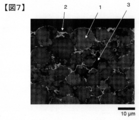
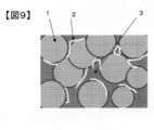
- FIG. 7 shows a mapping image of a secondary battery electrode manufactured in Example 2-1 described later.
- reference numeral 1 denotes cathode active material particles
- reference numeral 2 denotes a conductive additive made of graphene and fibrous carbon
- reference numeral 3 denotes a void and a binder.
- the data of the current collector is removed from the two-dimensional data of the spreading resistance value, and the data is obtained only for the mixture layer.
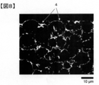
- FIG. 8 shows a binarized image of a secondary battery electrode prepared in Example 2-1 described later.
- Reference numeral 1 in a whitish portion is a positive electrode active material particle
- reference numeral 2 in a grayish color is a conductive additive.
- Reference numeral 3 in the dark portion indicates a void and a binder.
- FIG. 9 shows a model diagram of the mapping image of FIG.
- FIG. 8 is an image obtained by binarizing the mapping image shown in FIG. 7, and a portion (conductive material portion) having a resistance value of 0.7 R or less in FIG. 8 is a white portion indicated by reference numeral 4.
- the binarization process is a process in which a certain threshold value is provided to two-dimensional data, and the two-dimensional data is converted into two gradations (1 or 0) at the threshold value.
- a pixel value indicating a spreading resistance value of 0.7R or less is set to 1 (white), and a pixel value having a spreading resistance value higher than 0.7R is set to 0 (black). I do.
- a binarized image in which the conductive material portion is white and the other portions are black is obtained.
- image conversion software ImageJ free software
- the average aspect ratio of the conductive material portion can be obtained by reading the binarized image obtained as described above into image analysis software and analyzing it.
- image analysis software image analysis type particle size distribution measurement software ⁇ Mac-View ⁇ Ver. It is preferable to have a function of calculating the area, the aspect ratio, the distance between the centers of gravity, the circularity coefficient, and the perimeter as in 4.0.
- an image subjected to the binarization processing is captured, and a conductive material portion is selected.
- the selection of particles is performed by automatic selection.
- the automatic selection is performed with the acquisition mode being color difference, the permissible detection amount being 72 (highest), the detection accuracy being 0.5 (low), the scanning density being 10 (highest density), and the number of scans being three.
- the selection of the conductive material portion is completed by the automatic selection, if a portion where no conductive material portion exists (black portion) is selected, the selection is canceled.
- the scale is set based on the scale bar and the data is registered, whereby the preprocessing is completed, and the image analysis is automatically performed by calling the preprocessing data.
- a conductive material portion having an area of 0.5 ⁇ m 2 or less is excluded from the analysis during the image analysis.
- the average aspect ratio of the conductive material portion in the above-described binarized image reflects the ability to connect between active materials, that is, to maintain a conductive network when used repeatedly, and when it is less than 2.0, when it is repeatedly used. Electronic resistance tends to increase.
- the average aspect ratio is preferably 2.5 or more, more preferably 2.7 or more. Further, if the aspect ratio is too large, the dispersibility becomes worse, and the resistance may rather increase. Therefore, the average aspect ratio is preferably 5.0 or less, more preferably 3.0 or less. .
- the aspect ratio in the present specification refers to a rectangle circumscribing a selected conductive material portion, and when the area is minimized, the longer side of the rectangle is defined as the major axis and the shorter side is defined as the minor axis. It is a value divided by the diameter, and the average value of all the aspect ratios of the selected conductive material portion is defined as the average aspect ratio.
- the value obtained by dividing the average value of the major axis of the conductive material portion in the above-described binarized image by the median diameter of the active material particles for the secondary battery connects the active materials in the same manner as the average aspect ratio, that is, a network when repeatedly used. , And preferably 0.25 or more. When it is less than 0.25, the electronic aid tends to increase when repeatedly used because the conductive auxiliary is shorter than the active material.
- the value is more preferably 0.3 or more, and further preferably 0.35 or more.
- the circularity coefficient of the conductive material portion in the above-described binarized image is preferably 0.20 or less.
- the average value of all the selected conductive material portions is defined as a circularity coefficient.
- the circularity coefficient reflects the degree of agglomeration between the conductive material portions. If it exceeds 0.20, the agglomeration is large, the ratio of the portion where the conductive assistants are agglomerated becomes large, and the electron conduction between the active materials becomes large. The sex worsens.
- the circularity coefficient is more preferably 0.18 or less, and most preferably 0.17 or less.
- the average area of the conductive material portion in the above-described binarized image is less than 1.0 ⁇ m 2 , the electronic resistance as an electrode increases, and when it exceeds 1.6 ⁇ m 2 , the energy density decreases. It is preferably from 0.0% to 1.6 ⁇ m 2 .
- the average distance between the centers of gravity of the conductive material portions in the above-described binarized image is preferably 1.4 ⁇ m or more.
- the distance between the centers of gravity is based on the center of gravity of a certain conductive material portion, and the distance from the center of gravity to the center of gravity of the closest conductive material portion is defined as the distance between the centers of gravity.
- the average value of all the selected conductive material portions is the average distance between the centers of gravity.
- the average distance between the centers of gravity indicates the distance between the conductive material portions in the electrode. If the average center-to-center distance is less than 1.4 ⁇ m, the ratio of the conductive auxiliary agent having a low aspect ratio segregating becomes large, and the space is repeatedly used to form a void. When this happens, the electronic resistance increases.
- the distance between the centers of gravity is preferably 1.7 or more, and most preferably 1.9 or more.
- the circularity coefficient, the average area, and the average distance between the centers of gravity of the conductive material portions can be obtained by image analysis using the same binary image image analysis software as that for obtaining the above-mentioned aspect ratio.
- the ratio of the average circularity coefficient of the particles having an area of less than 0.5 ⁇ m 2 to the average circularity coefficient of the particles having an area of 0.5 ⁇ m 2 or more may be 1.50 or more. preferable.
- the portion having a small area and a high circularity coefficient has a role of forming a long-distance conductive path from the surface of the electrode to the current collector foil.
- the average circularity coefficient of particles having a particle size of less than 5 ⁇ m 2 increases.
- a portion having a large area and a small circularity coefficient has a role of forming a short-distance conductive path such as active material particles and conductive assistants.
- the average circularity coefficient of the particles having a size of 0.5 ⁇ m 2 or more is small.
- the ratio of these circularity coefficients indicates the degree to which graphene and fibrous carbon are well dispersed, and it has been found that a strong conductive network can be formed by setting the ratio to 1.50 or more. If the circularity coefficient ratio is less than 1.50, one of them is agglomerated, the roles of the short-range and long-distance conductive paths cannot be shared, and a strong conductive network cannot be formed. The life is shortened.
- the electrode for a secondary battery of the present invention typically has the above-mentioned mixture layer formed on a current collector.
- a metal foil or a metal mesh is preferably used as the current collector.
- an aluminum foil is preferably used for the positive electrode, and a copper foil is preferably used for the negative electrode.
- the electrode for a secondary battery of the present invention can be produced, for example, by preparing a graphene dispersion liquid and a fibrous carbon dispersion liquid described below, and then performing an electrode forming step described below.
- Graphene dispersion used in the present invention, as an example, A surface treatment step of mixing graphene oxide and a surface treatment agent having an acidic group in a solvent; A reduction step of reducing graphene oxide dispersed in a dispersion medium containing water; An organic solvent mixing step of mixing the intermediate dispersion having undergone the reduction step with an organic solvent; A strong stirring step of stirring the intermediate dispersion liquid containing an organic solvent at a peripheral speed of the rotary blade of the mixer of 6 m / s or more and 70 m / s or less; Can be produced by a production method including: Further, a cleaning step and a miniaturization step described below may be provided.
- the average circularity coefficient, the circularity coefficient ratio, the average aspect ratio, and the average distance between the centers of gravity of the particles having the above-mentioned area of 0.5 ⁇ m 2 or more are preferably set as described above. Can be easily adjusted to the range.
- graphene oxide There is no particular limitation on a method for manufacturing graphene oxide, and a known method such as a Hummers method can be used. Alternatively, commercially available graphene oxide may be purchased.
- Graphene oxide has high dispersibility, but is itself insulating and cannot be used as a conductive additive or the like. If the degree of oxidation of the graphene oxide is too high, the conductivity of the graphene powder obtained by reduction may deteriorate, so that the ratio of the carbon atoms to the oxygen atoms of the graphene oxide measured by X-ray photoelectron spectroscopy is as follows: It is preferably 0.5 or more. When measuring graphene oxide by X-ray photoelectron spectroscopy, the measurement is performed in a state where the solvent is sufficiently dried.
- the degree of oxidation of graphene oxide can be adjusted by changing the amount of oxidizing agent used for the oxidation reaction of graphite. Specifically, the higher the amount of sodium nitrate and potassium permanganate with respect to graphite used in the oxidation reaction, the higher the degree of oxidation, and the lower the amount, the lower the degree of oxidation.
- the weight ratio of sodium nitrate to graphite is not particularly limited, but is preferably 0.200 or more and 0.800 or less, more preferably 0.250 or more and 0.500 or less, and 0.275 or more. More preferably, it is 0.425 or less.
- the ratio of potassium permanganate to graphite is not particularly limited, but is preferably 1.00 or more, more preferably 1.40 or more, even more preferably 1.65 or more. Moreover, it is preferably 4.00 or less, more preferably 3.00 or less, and further preferably 2.55 or less.
- the graphene oxide is mixed with a surface treatment agent having an acidic group.
- the surface treatment agent exhibits an effect of increasing the dispersibility of graphene by being present at least in part on the surface of graphene, and is particularly effective for good dispersion of graphene in an organic solvent. This is important for forming a conductive network connecting the active materials in the final mixture layer.
- the acidic group is a hydroxy group, a phenolic hydroxy group, a nitro group, a carboxyl group, or a carbonyl group.
- the surface treating agent is not particularly limited as long as it is a compound having an acidic group, that is, a hydroxy group, a phenolic hydroxy group, a nitro group, a carboxyl group, or a carbonyl group, but a low molecular weight compound is preferred.
- a compound having a catechol group is preferable as a surface treatment agent because it has adhesiveness to graphene and dispersibility in a solvent.
- the compound having a catechol group include catechol, dopamine hydrochloride, 3- (3,4-dihydroxyphenyl) -L-alanine, 4- (1-hydroxy-2-aminoethyl) catechol, and 3,4-dihydroxybenzoic acid , 3,4-dihydroxyphenylacetic acid, caffeic acid, 4-methylcatechol and 4-tert-butylpyrocatechol.
- the surface treating agent may have a basic group in addition to the acidic group.
- the surface treating agent has an amino group to improve dispersibility. Therefore, a compound having both a catechol group and an amino group is particularly preferable as a surface treatment agent. Examples of such a compound include dopamine hydrochloride.
- the solvent used in the reduction step is preferably a polar solvent, such as water, ethanol, methanol, 1-propanol, 2-propanol, N-methylpyrrolidone, dimethylformamide, dimethylacetamide, dimethylsulfoxide, ⁇ -butyrolactone, or a mixture of the above.
- a polar solvent such as water, ethanol, methanol, 1-propanol, 2-propanol, N-methylpyrrolidone, dimethylformamide, dimethylacetamide, dimethylsulfoxide, ⁇ -butyrolactone, or a mixture of the above.
- the above-described surface treatment agent mixing step is performed in a solvent, the state after the completion of the step may be directly transferred to the reduction step, or may be diluted with the same solvent as the solvent used in the surface treatment agent mixing step. It is preferred to reduce.
- the method of reducing graphene oxide is not particularly limited, but chemical reduction is preferred.
- examples of the reducing agent include an organic reducing agent and an inorganic reducing agent, and an inorganic reducing agent is more preferable because of ease of washing after reduction.
- sodium dithionite, potassium dithionite, phosphorous acid, sodium borohydride, hydrazine and the like among which sodium dithionite and potassium dithionite, while relatively retaining an acidic group Since it can be reduced, graphene having high dispersibility in a solvent can be produced and is preferably used.
- miniaturization process Before, during, or during the reduction step, it is preferable to perform a miniaturization step of miniaturizing graphene oxide or reduced graphene contained in the intermediate dispersion before, during, or during the reduction step.
- the reduction step In order to obtain the graphene dispersion liquid used in the present invention, it is preferable to perform the reduction step in a state where the graphene oxide is refined. Therefore, the refinement step may be performed before the reduction step or during the reduction step. preferable.
- the size of graphene oxide or graphene in the plane direction can be made appropriate.
- the preferred size is as described above.
- the technique for making the particles fine it is obtained by mixing a plurality of grinding media such as beads and balls with a dispersion and causing the grinding media to collide with each other.
- a method of colliding a pressure-applied intermediate dispersion with a single ceramic ball, or a method of using a liquid-liquid shear-type wet jet mill that collides and disperses a pressure-applied intermediate dispersion with each other can be mentioned.
- a method of applying ultrasonic waves to the intermediate dispersion liquid is also a medialess dispersion method, and is a preferable method.
- graphene oxide or graphene tends to be miniaturized as the processing pressure or output in the medialess dispersion method increases, and as the processing time increases, the graphene tends to miniaturize.
- the preferred size of the graphene in the plane direction is as described above.
- the size of reduced graphene can be adjusted by the type, processing conditions, and processing time of the miniaturization treatment in the miniaturization step.
- Organic solvent mixing step In the organic solvent mixing step, the intermediate dispersion liquid and the organic solvent are mixed in order to replace water in the intermediate dispersion liquid after the reduction step with an organic solvent.
- the organic solvent mixing step the intermediate dispersion liquid obtained through the surface treatment step and the reduction step, or the intermediate dispersion liquid further subjected to a washing step and / or a miniaturization step as needed, and an organic solvent Mix directly. That is, from the end of the reduction step to the mixing with the organic solvent in the organic solvent mixing step, the intermediate dispersion is always in a dispersion state, and the dispersion medium is removed from the intermediate dispersion to recover graphene in a powder state. No operation such as freeze-drying is performed.
- a step of stirring the intermediate dispersion liquid containing the organic solvent at a peripheral speed of the rotary blade of the mixer of 6 m / s or more and 70 m / s is performed.
- Exfoliation of graphene in the strong stirring process can eliminate the stack of graphene, which is particularly effective for good dispersion of graphene in an organic solvent, and is a conductive material that connects active materials in the final mixture layer. It is important for network formation.
- a rotary blade mixer capable of giving such a strong stirring force to the intermediate dispersion liquid is referred to as a “strong stirring mixer”.
- the peripheral speed of the rotary blade of the mixer is preferably 10 m / s or more, more preferably 30 m / s or more.
- the peripheral speed of the rotary blade of the mixer is defined by peripheral length ⁇ rotation speed. If the peripheral speed is too low, peeling of graphene hardly occurs, and the degree of peeling of graphene decreases. On the other hand, if the peripheral speed is too high, the degree of peeling of graphene becomes too high, and the dispersibility decreases.
- the shear rate is more preferably 5,000 to 50,000 per second. If the shear rate is too low, peeling of graphene hardly occurs, and the degree of peeling of graphene decreases. On the other hand, if the shear rate is too high, the exfoliation degree of graphene becomes too high, and the dispersibility decreases.
- the shear rate is a value obtained by dividing the peripheral speed at the maximum diameter of the rotary blade of the mixer by the distance from the wall surface of the tip of the mixer rotary blade (the cutting edge that determines the maximum diameter).
- the processing time of the strong stirring step is preferably 15 seconds to 300 seconds, more preferably 20 seconds to 120 seconds, and still more preferably 30 seconds to 80 seconds.
- a planetary mixer with a disper or a device capable of obtaining a high peripheral speed such as robomix is preferable.
- the distance between the rotating blade and the wall surface such as a thin film turning method or a rotor / stator method is preferable.
- a mixer having a short shape of 10 mm or less and having a high shear force of a medialess system is more preferable.
- mixers having such a high shearing force for example, Fillmix (registered trademark) 30-30 type (manufactured by Primix), CLEARMIX (registered trademark) CLM-0.8S (manufactured by M Technic), Supershare And a mixer SDRT 0.35-0.75 (manufactured by Satake Chemical Machinery Co., Ltd.).
- Fillmix registered trademark
- CLEARMIX registered trademark
- CLM-0.8S manufactured by M Technic
- Supershare And a mixer SDRT 0.35-0.75 manufactured by Satake Chemical Machinery Co., Ltd.
- the solid content of the graphene dispersion is preferably 3.0% by mass or more and 20% by mass or less.
- the solid content is more preferably 10% by mass or less, and further preferably 5.0% by mass or less.
- the solid content rate is more preferably 3.0% by mass or more, and further preferably 4.0% by mass or more.
- the solid content of the graphene dispersion can be calculated by measuring the mass after drying the solvent from the graphene dispersion and dividing the measured value by the mass of the graphene dispersion itself. Specifically, about 1 g of a graphene dispersion liquid is adhered on a glass substrate having a known mass, and heated on a hot plate adjusted to a temperature of 120 ° C. for 1.5 hours to volatilize the solvent, and the mass of the graphene remaining when the solvent is volatilized. Is measured.
- Fibrous carbon dispersion As an example of a method for obtaining a fibrous carbon dispersion, a method in which fibrous carbon powder is directly mixed with an organic solvent is exemplified. At this time, it is preferable to use a dispersant.
- the dispersant include those exemplified as the dispersant contained in the mixture layer.
- the stirring processing is performed at a peripheral speed of the rotary blade of the mixer of 6 m / s or more and 70 m / s.
- the average circularity coefficient and the circularity coefficient ratio of the particles whose area is less than 0.5 ⁇ m 2 , and the average distance between the centers of gravity are within the above-described preferred ranges. It can be easily adjusted.
- a fibrous carbon dispersion having a solid content of 2.0% by mass or more and 20% by mass or less.
- the solid content is preferably 10% by mass or less, more preferably 5.0% by mass or less. Further, the solid content is preferably at least 3.0% by mass, more preferably at least 4.0% by mass.
- the solid content is 2.0% by mass or more, a shearing force is easily applied to the fibrous carbon during strong stirring, and the aggregated fibrous carbon can be easily loosened.
- the solid content is 20% by mass or less, the aggregation of the fibrous carbon in the dispersion is suppressed, and the viscosity is appropriately reduced, and strong stirring is easily performed. it can.
- Electrode conversion step As a first embodiment, after the active material particles and the above-described graphene dispersion liquid are strongly stirred at a peripheral speed of a rotary blade of a mixer of 6 m / s or more and 70 m / s or less, a binder solution of 5 mass% or more and 20 mass% or less is used. After that, the above-mentioned fibrous carbon dispersion liquid is subjected to a strong stirring treatment at a peripheral speed of the rotary blade of the mixer of 6 m / s or more and 70 m / s or less.
- An electrode paste is prepared so as to have a concentration of 65% by mass to 75% by mass, applied to a current collector foil, dried, and then pressed using a press machine, whereby an electrode for a secondary battery can be manufactured.
- the above-mentioned fibrous carbon dispersion is mixed with a mixer.
- a binder solution of 5.0 mass% or more and 20 mass% or less and an appropriate amount of a solvent are added as necessary, and the solid content concentration is 65%.
- An electrode paste is prepared so as to have a concentration of from 75% by mass to 75% by mass, applied to a current collector foil, dried, and then pressed by using a press machine to produce an electrode for a secondary battery.
- the graphene dispersion liquid and the carbon nanotube dispersion liquid are dried once before preparing the electrode paste, the cohesion becomes stronger, and therefore, it is important to perform the drying without drying to form a conductive network in the final mixture layer.
- the graphene dispersion liquid and the active material particles are subjected to strong stirring at a high concentration to apply a shearing force to the graphene and to promote the exfoliation. Therefore, the active material particles in the final mixture layer are further promoted. This is effective for forming a conductive network that connects them.
- the binder described above can be used. It is preferable that the binder is used after being dissolved in a solvent in advance.
- the solvent to be used include NMP, ⁇ -butyrolactone, water, dimethylacetamide and the like, and it is most preferable to use NMP which is a solvent contained in the graphene dispersion used in the present invention.
- the concentration of the binder solution is preferably 3% by mass or more and 20% by mass or less, more preferably 5% by mass or more and 10% by mass or less. If the concentration is too low, it is difficult to apply a shearing force to the graphene during strong stirring, and it becomes difficult to peel off. If the concentration is too high, the viscosity becomes too high, so that strong stirring cannot be performed, and it is difficult to maintain a good dispersion state.
- the secondary battery of the present invention includes the above-described electrode for a secondary battery, and preferably further includes a separator, an electrolyte, and an exterior member.
- the negative electrode can include a negative electrode current collector and a negative electrode active material-containing layer.
- the negative electrode active material-containing layer can be formed on one side or both sides of the negative electrode current collector.
- the negative electrode active material containing layer contains a negative electrode active material and can further contain a conductive agent and a binder.
- the negative electrode active material examples include lithium metals and lithium alloys; carbon-based active materials such as coke, artificial graphite, natural graphite, organic polymer compound burners, and carbon fibers; lithium such as Si, SiO x , Sn or SnO 2. And alloy-based active materials; such as titanium oxide, lithium titanium oxide, niobium titanium oxide, and sodium niobium titanium oxide. Two or more of these may be used. A carbon coat or an electron-conductive inorganic material coat may be applied to the surface of the negative electrode active material particles.
- the conductive agent is blended in order to enhance the current collecting performance and suppress the contact resistance between the negative electrode active material and the current collector.
- the conductive agent include carbon materials such as carbon nanotubes, acetylene black, carbon black, and graphite. Two or more of these may be used. Further, graphene or fibrous carbon with improved dispersibility described in the above electrode may be used.
- the binder is blended to fill gaps between the dispersed negative electrode active materials and to bind the negative electrode active material and the negative electrode current collector.
- the binder include polytetrafluoroethylene (PTFE), polyvinylidene fluoride (PVDF), fluorine-based rubber, styrene-butadiene rubber, polyacrylic acid compound, imide compound and the like. Two or more of these may be used.
- the active material, the conductive agent, and the binder in the negative electrode active material-containing layer are mixed at a ratio of 68% by mass or more and 96% by mass or less, 2% by mass or more and 30% by mass or less, and 2% by mass or more and 30% by mass or less. Is preferred.
- the negative electrode current collector is preferably made of copper, nickel, stainless steel, or aluminum, or an aluminum alloy containing one or more elements selected from Mg, Ti, Zn, Mn, Fe, Cu, and Si.
- the thickness of the negative electrode current collector is preferably in the range of 5 ⁇ m or more and 20 ⁇ m or less.
- the negative electrode can be produced, for example, by the following method. First, a negative electrode active material, a conductive agent and a binder are suspended in a solvent to prepare a slurry. This slurry is applied to one or both surfaces of the negative electrode current collector. Next, the applied slurry is dried to obtain a laminate of the negative electrode active material-containing layer and the negative electrode current collector. Thereafter, the laminate is pressed. Thus, a negative electrode is manufactured.
- the negative electrode may be manufactured by the following method. First, a negative electrode active material, a conductive agent, and a binder are mixed to obtain a mixture. Next, this mixture is formed into a pellet. Next, a negative electrode can be obtained by disposing these pellets on the negative electrode current collector.
- a liquid non-aqueous electrolyte As the electrolyte, a liquid non-aqueous electrolyte, a gel non-aqueous electrolyte, a room-temperature molten salt (ionic melt) containing lithium ions, a polymer solid electrolyte, an inorganic solid electrolyte, or the like can be used.
- the liquid non-aqueous electrolyte is prepared by dissolving an electrolyte such as LiPF6 in an organic solvent.
- the concentration of the electrolyte is preferably 0.5 mol / L or more and 5.0 mol / L or less.
- the gelled non-aqueous electrolyte is prepared by compounding a liquid non-aqueous electrolyte and a polymer material.
- the polymer material include polyvinylidene fluoride (PVDF), polyacrylonitrile (PAN), polyethylene oxide (PEO), and the like. Two or more of these may be used.
- Normal molten salt refers to a compound that can exist as a liquid at ordinary temperature (15 ° C. or more and 25 ° C. or less) among organic salts composed of a combination of organic cations and anions. Generally, the melting point of the room temperature molten salt used for the nonaqueous electrolyte battery is 25 ° C. or less.
- the organic cation generally has a quaternary ammonium skeleton.
- a polymer solid electrolyte is prepared by dissolving an electrolyte in a polymer material and solidifying it.
- the inorganic solid electrolyte is a solid substance having Li ion conductivity.
- Separator As the separator, it is preferable to use a porous film formed of polyethylene or polypropylene. This is because these porous films can be melted at a certain temperature and interrupt current.
- Exterior members for example, a container made of a laminated film or a metal container can be used.
- the shape of the exterior member is not particularly limited.
- the shape of the exterior member may be, for example, a flat type (thin type), a square type, a cylindrical type, a coin type, a button type, or the like.
- binarization processing was performed on all the two-dimensional data with 0.7R as a threshold.
- a pixel value indicating a resistance value of 0.7R or less is set to 1 (white)
- a pixel value having a resistance value higher than 0.7R is set to 0 (black)
- a binary image (white) is obtained by using ImageJ (free software).
- ImageJ free software
- Image analysis was performed on the obtained conductive material portion.
- image analysis type particle size distribution measurement software ⁇ Mac-View ⁇ Ver. Using 4.0 °, this was performed under the following automatic selection conditions.
- the acquisition mode was color difference, the permissible detection amount was 72 (highest), the detection accuracy was 0.5 (sweet), the scanning density was 10 (highest density), and the number of scans was three, and particles were automatically selected. Then, set the scale based on the scale bar mapping image, performs image analysis software, the average aspect ratio, average circularity coefficient less than the area 0.5 [mu] m 2, the area 0.5 [mu] m 2 or more average circularity coefficient, The average distance between the centers of gravity and the average major axis were obtained.
- a washing step of filtering with a reduced pressure suction filter, further diluting with water to 0.5% by mass, and performing suction filtration was repeated five times to wash.
- the mixture was diluted with NMP to 0.5% by mass, and treated with Fillmix (trademark) type 30-30 (Primix) at a peripheral speed of 40 m / s (shear speed: 40,000 per second) for 60 seconds (strong stirring step). ) And filtered with suction.
- the step of diluting with NMP to 0.5% by mass, treating with a homodisper 2.5 type (Primix) at a rotation speed of 3000 RPM for 30 minutes, and performing suction filtration is repeated four times to obtain a graphene NMP dispersion. Obtained.
- NMP was added to adjust the concentration of the dispersion to 4.0% by mass, and the dispersion was treated at a rotation speed of 20 RPM for 30 minutes using a planetary mixer.
- a graphene NMP dispersion (4.0% by mass) was obtained.
- NMP was added to the graphene powder, the concentration of the dispersion was adjusted to 2.0% by mass, and the mixture was treated at a rotation speed of 20 RPM for 30 minutes using a planetary mixer to obtain a graphene NMP dispersion (2.0% by mass). .
- Synthesis Example 5 Method for Preparing Graphene NMP Dispersion 4
- a graphene NMP dispersion (4.0% by mass) was obtained in the same manner as in Synthesis Example 2 except that the ultrasonic treatment device was not used.
- Example 1-1 0.5 parts by weight of the graphene dispersion liquid (4.0% by mass) prepared in Synthesis Example 2 as a conductive auxiliary agent as a graphene solid content, and polyvinylidene fluoride # 7200 (manufactured by Kureha Corporation) as a binder solid content of 1 part Then, the mixture was treated for 60 seconds at a peripheral speed of 40 m / s (shear speed: 40,000 per second) using Fillmix (registered trademark) Model 30-30 (Primix). The binder used herein was previously dissolved in NMP to form an 8.0% by mass solution.
- NCM LiNi 0.5 Co 0.2 Mn 0.3 O 2
- FIGS. 1 and 2 show the spread resistance value distribution image (mapping image) and the binarized image before binarization obtained by the method of Measurement Example 1 for the electrode plate.
- Example 1-2 The graphene dispersion (4.0% by mass) prepared in Synthesis Example 2 as a conductive aid was 0.25 parts by weight as a graphene solid, and the graphene dispersion (4.0% by mass) prepared in Synthesis Example 5 was graphene solid. 0.25 parts by weight as a binder, 1.0 part by weight of polyvinylidene fluoride # 7200 (manufactured by Kureha Co.) as a binder, and NMP as a solvent were added in a total amount of 43 parts by weight.
- An electrode plate was produced under the same conditions as in Example 1 except that it was added.
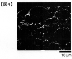
- FIGS. 3 and 4 show the spread resistance value distribution image (mapping image) and the binarized image before binarization obtained by the method of Measurement Example 1 for the electrode plate.
- Example 1-3 1.0 parts by weight of the graphene dispersion liquid (4.0% by mass) prepared in Synthesis Example 2 as a conductive aid was used as a graphene solid content, and polyvinylidene fluoride # 7200 (manufactured by Kureha Co., Ltd.) was used as a binder.
- An electrode plate was produced under the same conditions as in Example 1-1, except that 0 parts by weight was used and NMP was additionally added as a solvent so that the total amount became 50 parts by weight.
- Example 1-4 0.2 parts by weight of the graphene dispersion liquid (4.0% by mass) prepared in Synthesis Example 2 as a conductive aid was used as a graphene solid, and polyvinylidene fluoride # 7200 (manufactured by Kureha Co., Ltd.) was used as a binder.
- An electrode plate was prepared under the same conditions as in Example 1-1, except that 0 parts by weight was used and NMP was additionally added as a solvent so that the total amount became 40 parts by weight.
- Example 1-5 0.5 parts by weight of the graphene dispersion liquid (3.0% by mass) prepared in Synthesis Example 6 as a conductive auxiliary agent as a graphene solid content, and LiNi 0.5 Co 0.2 Mn 0.3 O 2 as active material particles (NCM) (100 parts by weight of granules having a median diameter of 10 ⁇ m is added, and the mixture is treated for 60 seconds at a peripheral speed of 40 m / s (shear speed: 40,000 per second) using Fillmix (registered trademark) Model 30-30 (Primix).
- NCM active material particles
- the mixture was mixed at a rotation speed of 30 RPM for 30 minutes using a planetary mixer, and then 1.0 part by weight of polyvinylidene fluoride # 7200 (manufactured by Kureha Co.) as a binder was added as a binder solid content, and NMP was used as a solvent in a total amount of 45 parts by weight. Parts by weight, and then mixed for 30 minutes at a rotation speed of 15 RPM using a planetary mixer to mix the electrode paste.
- the electrode paste was prepared by previously dissolving the binder in NMP to form a 5.0% by mass solution on an aluminum foil (thickness: 18 ⁇ m) using a doctor blade to give a basis weight of 15 mg / cm 2. After drying at 80 ° C. for 30 minutes, the resultant was pressed with a roll press machine, and vacuum dried using a vacuum dryer at 120 ° C. for 5 hours to obtain an electrode plate. Was 40 ⁇ m in thickness.
- the binder was used by previously dissolving it in NMP to form a 5% by mass solution.
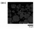
- FIGS. 5 and 6 show the spread resistance value distribution image (mapping image) and the binarized image before binarization obtained by the method of Measurement Example 1 for the electrode plate.
- Example 1-2 An electrode was prepared in the same manner as in Example 1-1, except that the graphene dispersion prepared in Synthesis Example 3 was used as a conductive additive, and NMP was additionally added as a solvent so that the total amount became 48 parts by weight. did.
- Example 1-3 An electrode was prepared in the same manner as in Example 1-1, except that the graphene dispersion prepared in Synthesis Example 4 was used as a conductive additive, and NMP was additionally added as a solvent to a total amount of 61 parts by weight. did.
- Example 1-4 An electrode was prepared in the same manner as in Example 1-1, except that the graphene dispersion prepared in Synthesis Example 2 was used as a conductive additive, and NMP was additionally added as a solvent so that the total amount became 60 parts by weight. did.
- Example 1-5 An electrode was prepared in the same manner as in Example 1-1, except that the graphene dispersion prepared in Synthesis Example 2 was used as a conductive additive, and NMP was additionally added as a solvent to a total amount of 70 parts by weight. did.
- the average circularity coefficient having an area of less than 0.5 ⁇ m 2 , the average circularity coefficient having an area of 0.5 ⁇ m 2 or more, and the average circularity obtained by subjecting the electrodes produced in each of the examples and comparative examples to image analysis by the method of Measurement Example 1 Tables 1 and 2 summarize the battery ratio evaluation results by the coefficient ratio, average aspect ratio, average center-of-gravity distance, average major axis / active material median diameter, and the method of Measurement Example 2.
- Example 2-1 Graphene dispersion liquid 1 (4.0% by mass) prepared in Synthesis Example 2 as a conductive additive was 0.5 parts by mass as a graphene solid content, and LiNi 0.5 Co 0.2 Mn 0.3 O was used as active material particles. 100 parts by mass of 2 (NCM) (manufactured by Umicore, granules having a median diameter of 10 ⁇ m) were added, and mixed at a rotation speed of 30 RPM for 30 minutes using a planetary mixer.
- NCM manufactured by Umicore, granules having a median diameter of 10 ⁇ m
- the electrode paste was obtained using “Fillmix” (registered trademark) Model 30-30 (Primix) at a peripheral speed of 40 m / s (shear speed: 40,000 per second) for 60 seconds.
- This electrode paste was applied to an aluminum foil (thickness: 18 ⁇ m) using a doctor blade so as to have a basis weight of 1.5 mg / cm 2 , dried at 80 ° C. for 30 minutes, pressed by a roll press, and dried by a vacuum dryer. The resultant was vacuum-dried at 120 ° C. for 5 hours to obtain an electrode.
- the thickness of the electrode mixture layer (excluding the aluminum foil) was 40 ⁇ m.
- FIGS. 7 and 8 show the spread resistance value distribution image (mapping image) and the binarized image before binarization obtained by the method of Measurement Example 1 for the electrodes.
- Example 2-2 0.15 parts by mass of the graphene dispersion liquid 1 (4.0% by mass) prepared in Synthesis Example 2 as a conductive assistant was 0.15 parts by mass as a graphene solid content, and 0.1% by mass of the fibrous carbon dispersion liquid 1 prepared in Synthesis Example 7 as a solid content.
- An electrode was produced under the same conditions as in Example 2-1 except that 35 parts by mass and NMP as a solvent were additionally added so as to be a total amount of 30 parts by mass.
- Example 2-3 Graphene dispersion liquid 1 (4.0% by mass) prepared in Synthesis Example 2 was 0.35 parts by mass as a graphene solid content, and fibrous carbon dispersion liquid 1 prepared in Synthesis Example 7 was 0.1% by mass as a conductive auxiliary.
- An electrode was produced under the same conditions as in Example 2-1 except that 15 parts by mass and NMP as a solvent were additionally added so as to be a total amount of 33 parts by mass.
- Example 2-4 Graphene dispersion liquid 1 (4.0% by mass) prepared in Synthesis Example 2 as a conductive aid was 0.25 parts by mass as a graphene solid content, and fibrous carbon dispersion liquid 1 prepared in Synthesis Example 7 was 0.1% as a solid content.
- An electrode was produced under the same conditions as in Example 2-1 except that 25 parts by mass and NMP as a solvent were additionally added so as to be a total amount of 32 parts by mass.
- Example 2-5 Graphene dispersion liquid 1 (4.0% by mass) prepared in Synthesis Example 2 as a conductive assistant was 0.5 parts by mass as a graphene solid content, and fibrous carbon dispersion liquid 2 (4.0% by mass) prepared in Synthesis Example 8 ) was added under the same conditions as in Example 2-1 except that 0.5 parts by mass as solid content and NMP as a solvent were further added so as to be 50 parts by mass in total.
- Example 2-6 Graphene dispersion 3 (4.0% by mass) prepared in Synthesis Example 4 as a conductive aid was 0.25 parts by mass as a graphene solid content, and fibrous carbon dispersion liquid 1 prepared in Synthesis Example 7 was 0.2% by mass as a solid content.
- An electrode was produced under the same conditions as in Example 2-1 except that 25 parts by mass and NMP as a solvent were additionally added so as to be a total amount of 33 parts by mass.
- Example 2-7 Graphene dispersion liquid 1 (4.0% by mass) prepared in Synthesis Example 2 as a conductive assistant was 0.25 parts by mass as a graphene solid content, and fibrous carbon dispersion liquid 3 prepared in Synthesis Example 9 was 0.1% as a solid content.
- An electrode was produced under the same conditions as in Example 2-1 except that 25 parts by mass and NMP as a solvent were additionally added so as to be a total amount of 31 parts by mass.
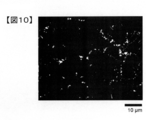
- FIG. 10 shows a binarized image of the electrode plate obtained by the method of Measurement Example 1.
- NMP was additionally added as a solvent so as to have a total amount of 35 parts by mass, and then mixed at a rotation speed of 1.5 RPM for 30 minutes using a planetary mixer to obtain an electrode paste.
- the electrode paste is applied to an aluminum foil (thickness: 18 ⁇ m) using a doctor blade, dried at 80 ° C. for 30 minutes, pressed by a roll press, and vacuum dried at 120 ° C. for 5 hours using a vacuum dryer. An electrode was obtained.
- the thickness of the electrode mixture layer (excluding the aluminum foil) was 40 ⁇ m.
- Example 2 except that the graphene dispersion liquid 2 (4.0% by mass) prepared in Synthesis Example 3 was used as a conductive additive and NMP was additionally added as a solvent so that the total amount became 50 parts by mass.
- An electrode plate was produced under the same conditions as in -1.
- the average circularity coefficient having an area of less than 0.5 ⁇ m 2 , the average circularity coefficient having an area of 0.5 ⁇ m 2 or more, and the average were obtained by performing image analysis on the electrodes prepared in each of the Examples and Comparative Examples by the method of Measurement Example 1.
- Tables 3 and 4 summarize the battery performance evaluation results by the ratio of the circularity coefficient, the average aspect ratio, the average distance between the centers of gravity, the average major axis / active material median diameter, and the method of Measurement Example 2.
Abstract
Description
グラフェンと、少なくともリチウムとニッケルを含む二次電池用活物質粒子とを含む合剤層を有する二次電池用電極であって、
下記の方法により特定される該二次電池用電極の断面における導電材料部分の平均アスペクト比が2.0以上である二次電池用電極。
導電材料部分の特定方法:
(1)走査広がり抵抗顕微鏡法で合剤層部分の広がり抵抗値を取得する。
(2)上記広がり抵抗値の全データ数をNとした時に、広がり抵抗値を小さい順に並び替え、0.1N番目(0.1Nの小数点以下は切り捨て)の広がり抵抗値をRとし、
0.7Rを閾値として広がり抵抗値の二次元データに対して二値化処理を行い、得られた二値化画像において0.7R以下の抵抗値を有する部分を導電材料部分とする。 The present invention for solving the above problems,
Graphene, a secondary battery electrode having a mixture layer including at least lithium and nickel-containing secondary battery active material particles,
A secondary battery electrode in which the average aspect ratio of the conductive material portion in the cross section of the secondary battery electrode specified by the following method is 2.0 or more.
Method of specifying conductive material part:
(1) Obtain the spread resistance value of the mixture layer portion by scanning spread resistance microscopy.
(2) When the total number of data of the spreading resistance value is N, the spreading resistance values are rearranged in ascending order, and the 0.1N-th (0.1N fractional part is rounded down) spreading resistance value is R,
Binarization processing is performed on the two-dimensional data of the spreading resistance value with 0.7R as a threshold, and a portion having a resistance value of 0.7R or less in the obtained binary image is defined as a conductive material portion.
本発明の二次電池用電極(以下、単に「電極」という場合がある)は、グラフェンと、二次電池用活物質粒子とを含む合剤層を有する。 <Electrode for secondary battery>
The electrode for a secondary battery of the present invention (hereinafter sometimes simply referred to as “electrode”) has a mixture layer containing graphene and active material particles for a secondary battery.
本発明の二次電池用電極においては、導電助剤として、薄く、面形状で、単位重量当りの導電パスが多く、電極内において強固な導電ネットワークを形成しやすいグラフェンを用いる。グラフェンとは、狭義には1原子の厚さのsp2結合炭素原子のシート(単層グラフェン)を指すが、本明細書においては、単層グラフェンが積層した薄片状の形態を持つものも含めてグラフェンと呼ぶ。また、酸化グラフェンも同様に、積層した薄片状の形態を持つものも含めた呼称とする。 (Graphene)
In the electrode for a secondary battery according to the present invention, graphene, which is thin, has a planar shape, has a large number of conductive paths per unit weight, and easily forms a strong conductive network in the electrode, is used as the conductive additive. Graphene is in a narrow sense refers to a 1 thickness sp 2 bonded carbon atoms of the atoms sheet (monolayer graphene), in this specification, including those monolayer graphene has a flaky form laminated Called graphene. Similarly, graphene oxide is also referred to as having a laminated flake shape.
本発明の二次電池用電極においては、導電助剤として、繊維状カーボンを含むことが好ましい。導電助剤としてグラフェンのみを含む場合、乾燥による溶媒除去などの製造工程において、一部凝集する場合がある。グラフェンに繊維状カーボンを組み合わせることにより、グラフェンに繊維状カーボンがπ-π相互作用により橋かけするため、グラフェンや繊維状カーボン同士の凝集を抑制することができる。また、繊維状カーボンにより活物質粒子同士も橋かけし、さらに面形状のグラフェンにより橋かけ部分が補強されるため、電極全体に渡って強固な3次元的な導電ネットワークの形成が可能となる。 (Fibrous carbon)
In the secondary battery electrode of the present invention, it is preferable that fibrous carbon is contained as the conductive assistant. In the case where only graphene is included as the conductive additive, in a manufacturing process such as removal of a solvent by drying, a part of the graphene may be aggregated. When fibrous carbon is combined with graphene, fibrous carbon bridges graphene by π-π interaction, so that aggregation of graphene and fibrous carbon can be suppressed. In addition, the active material particles are also bridged by the fibrous carbon, and the bridged portion is reinforced by the planar graphene, so that a strong three-dimensional conductive network can be formed over the entire electrode.
本発明に用いる二次電池用活物質は、少なくともリチウムとニッケルを含む、リチウムイオンを電気化学的に吸蔵・放出可能な二次電池用活物質である。このような二次電池用活物質の一例としては、ニッケル酸リチウム(LiNiO2)、ニッケルをマンガン・コバルトなどの遷移元素で一部置換した三元系(LixNiyMnZCo1-y-ZO2)(0.8≦x≦1.5、y≧0、z≧0、y+z≦1を表す。)、コバルト・アルミニウムで一部置換した三元系(LixNiyCozAl1-y-zO2)(0.8≦x≦1.5、y≧0、z≧0、y+z≦1を表す。)、あるいは固溶体系活物質などを用いることができるが、少なくともリチウムとニッケルを含んでいれば良く、上記に限定されない。 (Active material particles for secondary batteries)
The secondary battery active material used in the present invention is a secondary battery active material containing at least lithium and nickel and capable of electrochemically absorbing and releasing lithium ions. Examples of such an active material for a secondary battery include lithium nickelate (LiNiO 2 ) and a ternary system in which nickel is partially substituted with a transition element such as manganese / cobalt (Li x Ni y Mn Z Co 1 -y). —Z O 2 ) (representing 0.8 ≦ x ≦ 1.5, y ≧ 0, z ≧ 0, y + z ≦ 1), and a ternary system partially substituted with cobalt aluminum (Li x Ni y Co z Al 1-y-z O 2 ) (representing 0.8 ≦ x ≦ 1.5, y ≧ 0, z ≧ 0, y + z ≦ 1), or a solid-solution active material can be used. It is sufficient that lithium and nickel are included, and the invention is not limited to the above.
円形度係数=(4π×粒子面積)/(周囲長)2
平均円形度係数は、個々の粒子50個に対して円形度係数を求め、平均した値である。 The average circularity coefficient of the active material particles for a secondary battery used in the present invention is preferably 0.8 or more and 1.0 or less. If the average circularity coefficient is less than 0.8, graphene tends to be unevenly distributed only around the active material, the effect of connecting the active materials is weakened, and a strong conductive network cannot be formed. The circularity coefficient is a value obtained by dividing the area of a particle by 4π times the square of the perimeter, and is represented by the following equation.
Circularity coefficient = (4π × particle area) / (perimeter) 2
The average circularity coefficient is a value obtained by averaging circularity coefficients for 50 individual particles.
本発明の二次電池用電極は、分散剤を含むことが好ましい。本発明における分散剤とは、N-メチルピロリドン(NMP)にグラフェンまたはカーボンナノチューブなどの炭素系材料を均一に分散可能な材料を言う。分散剤を用いることにより、繊維状カーボンおよびグラフェンの分散性をより向上させ、出力特性および寿命をより向上させることができる。さらに、分散剤は、繊維状カーボンおよびグラフェンそれぞれの分散性をより向上させるだけでなく、後述する電極化工程で示すような高せん断が生じる条件化でペースト作製を行うことにより、グラフェンにせん断力がかかり、剥離がより促されるため、最終的な合剤層における活物質粒子間を繋ぐ導電ネットワーク形成に有効となり、後述の円形度係数比や平均重心間距離を前述の好ましい範囲に容易に調整することができる。分散剤としては、例えば、ポリビニルピロリドン、エチルセルロースなど耐酸化性に優れるものが好ましい。これらを2種以上含んでもよい。 (Dispersant)
The electrode for a secondary battery of the present invention preferably contains a dispersant. The dispersant in the present invention refers to a material capable of uniformly dispersing a carbon-based material such as graphene or carbon nanotube in N-methylpyrrolidone (NMP). By using a dispersant, the dispersibility of fibrous carbon and graphene can be further improved, and the output characteristics and life can be further improved. Furthermore, the dispersant not only improves the dispersibility of each of the fibrous carbon and graphene, but also performs a paste preparation under conditions where high shear occurs as shown in an electrode forming step described below, thereby imparting a shear force to the graphene. Is applied, and peeling is further promoted, which is effective for forming a conductive network connecting the active material particles in the final mixture layer, and easily adjusts the circularity coefficient ratio and the average distance between the centers of gravity described below to the preferable ranges described above. can do. As the dispersant, for example, those having excellent oxidation resistance such as polyvinylpyrrolidone and ethyl cellulose are preferable. Two or more of these may be included.
合剤層は、二次電池用活物質粒子とグラフェンを含み、典型的にはさらにバインダーを含む。合剤層のグラフェンおよび二次電池用活物質は、前述のものを用いることができる。バインダーとしては、特に限定されないが、ポリフッ化ビニリデン(PVDF)、ポリテトラフルオロエチレン(PTFE)などのフッ素系重合体、あるいはスチレンブタジエンゴム(SBR)、天然ゴムなどのゴム、カルボキシメチルセルロース等の多糖類、ポリイミド前駆体および/またはポリイミド樹脂、ポリアミドイミド樹脂、ポリアミド樹脂、ポリアクリル酸、ポリアクリル酸ナトリウム、アクリル樹脂、ポリアクリロニトリル等が挙げられる。これらは2種以上の混合物として用いてもよい。バインダーは、少なすぎると結着強度が弱くなり、多すぎると抵抗が大きくなるため、合剤層中におけるバインダーの含有量は、二次電池用活物質粒子に対して0.10質量%以上3.0質量%以下であることが好ましく、0.20質量%以上1.5質量%であることがより好ましく、0.20質量%以上0.75質量%以下であることが、塗工性およびエネルギー密度向上の上で、さらに好ましい。 (Mixture layer)
The mixture layer contains active material particles for a secondary battery and graphene, and typically further contains a binder. As the graphene and the active material for a secondary battery in the mixture layer, those described above can be used. The binder is not particularly limited, but a fluorine-based polymer such as polyvinylidene fluoride (PVDF) or polytetrafluoroethylene (PTFE), a rubber such as styrene butadiene rubber (SBR) or natural rubber, or a polysaccharide such as carboxymethyl cellulose. , A polyimide precursor and / or a polyimide resin, a polyamide imide resin, a polyamide resin, polyacrylic acid, sodium polyacrylate, an acrylic resin, and polyacrylonitrile. These may be used as a mixture of two or more. When the amount of the binder is too small, the binding strength becomes weak, and when the amount is too large, the resistance becomes large. Therefore, the content of the binder in the mixture layer is 0.10% by mass or more with respect to the active material particles for a secondary battery. 0.0% by mass or less, more preferably 0.20% by mass or more and 1.5% by mass, and more preferably 0.20% by mass or more and 0.75% by mass or less. It is more preferable from the viewpoint of improving energy density.
(1)まず、走査広がり抵抗顕微鏡法(SSRM)で合剤層部分の広がり抵抗値を取得する。 (Specifying method of conductive material part)
(1) First, the spread resistance value of the mixture layer portion is obtained by scanning spread resistance microscopy (SSRM).
円形度係数=(4π×粒子面積)/(周囲長)2。 The circularity coefficient of the conductive material portion in the above-described binarized image is preferably 0.20 or less. The circularity coefficient is a value obtained by dividing the area of a particle by 4π times the square of the perimeter, and is represented by the following equation.
Circularity coefficient = (4π × particle area) / (perimeter) 2 .
また、面積が0.5μm2以上である粒子の平均円形度係数に対する面積が0.5μm2未満である粒子の平均円形度係数の比(円形度係数比)が1.50以上であることが好ましい。 (Circularity coefficient ratio)
Further, the ratio of the average circularity coefficient of the particles having an area of less than 0.5 μm 2 to the average circularity coefficient of the particles having an area of 0.5 μm 2 or more (circularity coefficient ratio) may be 1.50 or more. preferable.
本発明の二次電池用電極は、典型的には前述の合剤層が集電体上に形成されてなるものである。集電体としては、金属箔あるいは金属メッシュが好ましく用いられ、特に正極ではアルミニウム箔が、負極には銅箔が好ましく用いられる。 (Current collector)
The electrode for a secondary battery of the present invention typically has the above-mentioned mixture layer formed on a current collector. As the current collector, a metal foil or a metal mesh is preferably used. In particular, an aluminum foil is preferably used for the positive electrode, and a copper foil is preferably used for the negative electrode.
本発明の二次電池用電極は、例えば、後述するグラフェン分散液および繊維状カーボン分散液を作製した後、後述する電極化工程により製造することができる。 (Production method of electrode for secondary battery)
The electrode for a secondary battery of the present invention can be produced, for example, by preparing a graphene dispersion liquid and a fibrous carbon dispersion liquid described below, and then performing an electrode forming step described below.
本発明に用いられるグラフェン分散液は、一例として、
酸化グラフェンと、酸性基を有する表面処理剤とを溶媒中で混合する表面処理工程;
水を含む分散媒に分散した酸化グラフェンを還元する還元工程;
還元工程を経た中間体分散液と有機溶媒とを混合する有機溶媒混合工程;
有機溶媒を含む中間体分散液をミキサーの回転刃の周速6m/s以上70m/s以下で撹拌処理する強撹拌工程;
を含む製造方法により作製することができる。さらに、後述する洗浄工程や微細化工程を有してもよい。かかる製造方法により得られるグラフェン分散液を用いることにより、前述の面積が0.5μm2以上である粒子の平均円形度係数や、円形度係数比、平均アスペクト比、平均重心間距離を前述の好ましい範囲に容易に調整することができる。 (Graphene dispersion)
Graphene dispersion used in the present invention, as an example,
A surface treatment step of mixing graphene oxide and a surface treatment agent having an acidic group in a solvent;
A reduction step of reducing graphene oxide dispersed in a dispersion medium containing water;
An organic solvent mixing step of mixing the intermediate dispersion having undergone the reduction step with an organic solvent;
A strong stirring step of stirring the intermediate dispersion liquid containing an organic solvent at a peripheral speed of the rotary blade of the mixer of 6 m / s or more and 70 m / s or less;
Can be produced by a production method including: Further, a cleaning step and a miniaturization step described below may be provided. By using the graphene dispersion obtained by such a production method, the average circularity coefficient, the circularity coefficient ratio, the average aspect ratio, and the average distance between the centers of gravity of the particles having the above-mentioned area of 0.5 μm 2 or more are preferably set as described above. Can be easily adjusted to the range.
酸化グラフェンの作製法に特に限定は無く、ハマーズ法等の公知の方法を使用できる。また市販の酸化グラフェンを購入してもよい。 (Graphene oxide)
There is no particular limitation on a method for manufacturing graphene oxide, and a known method such as a Hummers method can be used. Alternatively, commercially available graphene oxide may be purchased.
表面処理工程においては、酸化グラフェンを、酸性基を有する表面処理剤と混合する。表面処理剤は、少なくともその一部がグラフェンの表面に付着して存在していることで、グラフェンの分散性を高める効果を発揮するものであり、有機溶媒中におけるグラフェンの良分散化に特に有効であり、最終的な合剤層における活物質間を繋ぐ導電ネットワーク形成に重要となる。 (Surface treatment step)
In the surface treatment step, the graphene oxide is mixed with a surface treatment agent having an acidic group. The surface treatment agent exhibits an effect of increasing the dispersibility of graphene by being present at least in part on the surface of graphene, and is particularly effective for good dispersion of graphene in an organic solvent. This is important for forming a conductive network connecting the active materials in the final mixture layer.
還元工程では、水を含む分散媒に分散した酸化グラフェンを還元する。還元工程で用いる溶媒としては、極性溶媒が好ましく、水、エタノール、メタノール、1-プロパノール、2-プロパノール、N-メチルピロリドン、ジメチルホルムアミド、ジメチルアセトアミド、ジメチルスルホキシド、γ-ブチロラクトン、或いは上記の混合物等が好ましい例として挙げられる。また、前述の表面処理剤混合工程を溶媒中で行う場合には、当該工程の終了後の状態でそのまま還元工程に移るか、あるいは表面処理剤混合工程で用いた溶媒と同じ溶媒で希釈して還元することが好ましい。 (Reduction step)
In the reduction step, the graphene oxide dispersed in the dispersion medium containing water is reduced. The solvent used in the reduction step is preferably a polar solvent, such as water, ethanol, methanol, 1-propanol, 2-propanol, N-methylpyrrolidone, dimethylformamide, dimethylacetamide, dimethylsulfoxide, γ-butyrolactone, or a mixture of the above. Are preferred examples. When the above-described surface treatment agent mixing step is performed in a solvent, the state after the completion of the step may be directly transferred to the reduction step, or may be diluted with the same solvent as the solvent used in the surface treatment agent mixing step. It is preferred to reduce.
還元工程を終えた後、好ましくは水で希釈し濾過する洗浄工程を行うことで、グラフェンの純度が向上し、グラフェンが水に分散したゲル状の分散液が得られる。なお、本明細書においては、最終的に完成したグラフェン分散液以外の、グラフェンまたは酸化グラフェンが何らかの分散媒に分散した状態にある製造途中の中間体を、ゲル状のものも含め、便宜的に全て「中間体分散液」と呼ぶものとする。 (Washing process)
After the reduction step, preferably, a washing step of diluting with water and filtering is performed, whereby the purity of the graphene is improved, and a gel dispersion in which the graphene is dispersed in the water is obtained. In the present specification, other than the finally completed graphene dispersion liquid, intermediates in the course of production in which graphene or graphene oxide is dispersed in any dispersion medium, including those in the form of gel, are conveniently included. All shall be referred to as "intermediate dispersions".
還元工程の前後、または最中に、還元工程の前後または還元工程の最中の中間体分散液に含まれる酸化グラフェンまたは還元後のグラフェンを微細化する微細化工程を行うことが好ましい。本発明で使用するグラフェン分散液を得るためには、酸化グラフェンを微細化した状態で還元工程を行うことが好ましいことから、微細化工程は還元工程の前または還元工程の最中に行うことが好ましい。 (Miniaturization process)
Before, during, or during the reduction step, it is preferable to perform a miniaturization step of miniaturizing graphene oxide or reduced graphene contained in the intermediate dispersion before, during, or during the reduction step. In order to obtain the graphene dispersion liquid used in the present invention, it is preferable to perform the reduction step in a state where the graphene oxide is refined. Therefore, the refinement step may be performed before the reduction step or during the reduction step. preferable.
有機溶媒混合工程においては、還元工程後の中間体分散液中の水を有機溶媒に置換するために、中間体分散液と有機溶媒とを混合する。有機溶媒混合工程においては、表面処理工程および還元工程を経て得られた中間体分散液、または必要に応じてさらに洗浄工程および/または微細化工程を行った中間体分散液と、有機溶媒とを直接混合する。すなわち、還元工程終了後から有機溶媒混合工程における有機溶媒との混合まで、中間体分散液は常に分散液の状態にあり、中間体分散液から分散媒を除去してグラフェンを粉末状態として回収する凍結乾燥等の操作は行わない。 (Organic solvent mixing step)
In the organic solvent mixing step, the intermediate dispersion liquid and the organic solvent are mixed in order to replace water in the intermediate dispersion liquid after the reduction step with an organic solvent. In the organic solvent mixing step, the intermediate dispersion liquid obtained through the surface treatment step and the reduction step, or the intermediate dispersion liquid further subjected to a washing step and / or a miniaturization step as needed, and an organic solvent Mix directly. That is, from the end of the reduction step to the mixing with the organic solvent in the organic solvent mixing step, the intermediate dispersion is always in a dispersion state, and the dispersion medium is removed from the intermediate dispersion to recover graphene in a powder state. No operation such as freeze-drying is performed.
有機溶媒混合工程の後、有機溶媒を含む中間体分散液をミキサーの回転刃の周速6m/s以上70m/sで撹拌処理する工程(強撹拌工程)を実施する。強撹拌工程でグラフェンを剥離することで、グラフェン同士のスタックを解消することができ、有機溶媒中におけるグラフェンの良分散化に特に有効であり、最終的な合剤層における活物質間を繋ぐ導電ネットワーク形成に重要となる。なお、本明細書においては、中間体分散液にこのような強い攪拌力を与えられる回転刃ミキサーを「強攪拌ミキサー」と呼ぶ。 (Strong stirring process)
After the organic solvent mixing step, a step of stirring the intermediate dispersion liquid containing the organic solvent at a peripheral speed of the rotary blade of the mixer of 6 m / s or more and 70 m / s (strong stirring step) is performed. Exfoliation of graphene in the strong stirring process can eliminate the stack of graphene, which is particularly effective for good dispersion of graphene in an organic solvent, and is a conductive material that connects active materials in the final mixture layer. It is important for network formation. In the present specification, a rotary blade mixer capable of giving such a strong stirring force to the intermediate dispersion liquid is referred to as a “strong stirring mixer”.
繊維状カーボン分散液を得る方法としては、一例として、繊維状カーボン粉末を有機溶媒と直接混合する方法が挙げられる。この時、分散剤を用いることが好ましい。分散剤としては、合剤層に含まれる分散剤として例示したものが挙げられる。分散剤を用いることにより、繊維状カーボンの分散性を高めることに加え、一旦剥離したグラフェンに繊維状カーボンや分散剤が入り込むことにより分散状態が維持しやすくなる。その後、「強撹拌ミキサー」を用いて、ミキサーの回転刃の周速6m/s以上70m/sで撹拌処理する。かかる製造方法により得られる繊維状カーボン分散液を用いることにより、前述の面積が0.5μm2未満である粒子の平均円形度係数や、円形度係数比、平均重心間距離を前述の好ましい範囲に容易に調整することができる。 (Fibrous carbon dispersion)
As an example of a method for obtaining a fibrous carbon dispersion, a method in which fibrous carbon powder is directly mixed with an organic solvent is exemplified. At this time, it is preferable to use a dispersant. Examples of the dispersant include those exemplified as the dispersant contained in the mixture layer. By using the dispersant, the dispersibility of the fibrous carbon is enhanced, and the dispersed state is easily maintained by the fibrous carbon and the dispersant entering the graphene that has been peeled once. Thereafter, using a “strong stirring mixer”, the stirring processing is performed at a peripheral speed of the rotary blade of the mixer of 6 m / s or more and 70 m / s. By using the fibrous carbon dispersion obtained by such a production method, the average circularity coefficient and the circularity coefficient ratio of the particles whose area is less than 0.5 μm 2 , and the average distance between the centers of gravity are within the above-described preferred ranges. It can be easily adjusted.
第1の態様として、活物質粒子および前述のグラフェン分散液を、ミキサーの回転刃の周速6m/s以上70m/s以下で強撹拌処理した後、5質量%以上20質量%以下のバインダー溶液を加え、その後、前述の繊維状カーボン分散液を、ミキサーの回転刃の周速6m/s以上70m/s以下で強撹拌処理した後、必要に応じて適量の溶媒を加え、固形分濃度が65質量%~75質量%になるように電極ペーストを調製し、集電箔に塗布し、乾燥した後、プレス機を用いてプレスを行うことにより二次電池用電極を製造することができる。 (Electrode conversion step)
As a first embodiment, after the active material particles and the above-described graphene dispersion liquid are strongly stirred at a peripheral speed of a rotary blade of a mixer of 6 m / s or more and 70 m / s or less, a binder solution of 5 mass% or more and 20 mass% or less is used. After that, the above-mentioned fibrous carbon dispersion liquid is subjected to a strong stirring treatment at a peripheral speed of the rotary blade of the mixer of 6 m / s or more and 70 m / s or less. An electrode paste is prepared so as to have a concentration of 65% by mass to 75% by mass, applied to a current collector foil, dried, and then pressed using a press machine, whereby an electrode for a secondary battery can be manufactured.
本発明の二次電池は、前述の二次電池用電極を備えてなり、さらにセパレータ、電解質および外装部材を有することが好ましい。 <Secondary battery>
The secondary battery of the present invention includes the above-described electrode for a secondary battery, and preferably further includes a separator, an electrolyte, and an exterior member.
負極は、負極集電体と、負極活物質含有層とを含むことができる。負極活物質含有層は、負極集電体の片面又は両面に形成され得る。負極活物質含有層は、負極活物質を含有し、さらに導電剤やバインダーを含むことができる。 (Negative electrode)
The negative electrode can include a negative electrode current collector and a negative electrode active material-containing layer. The negative electrode active material-containing layer can be formed on one side or both sides of the negative electrode current collector. The negative electrode active material containing layer contains a negative electrode active material and can further contain a conductive agent and a binder.
正極として、前述の電極を用いることが好ましい。 (Positive electrode)
It is preferable to use the above-mentioned electrode as the positive electrode.
電解質としては、液状非水電解質、ゲル状非水電解質、リチウムイオンを含有した常温溶融塩(イオン性融体)、高分子固体電解質、無機固体電解質等を用いることができる。液状非水電解質は、LiPF6などの電解質を有機溶媒に溶解することにより調製される。電解質の濃度は、0.5mol/L以上5.0mol/L以下であることが好ましい。 〔Electrolytes〕
As the electrolyte, a liquid non-aqueous electrolyte, a gel non-aqueous electrolyte, a room-temperature molten salt (ionic melt) containing lithium ions, a polymer solid electrolyte, an inorganic solid electrolyte, or the like can be used. The liquid non-aqueous electrolyte is prepared by dissolving an electrolyte such as LiPF6 in an organic solvent. The concentration of the electrolyte is preferably 0.5 mol / L or more and 5.0 mol / L or less.
セパレータとしては、ポリエチレン又はポリプロピレンから形成された多孔質フィルムを用いることが好ましい。これらの多孔質フィルムは、一定温度において溶融し、電流を遮断することが可能なためである。 [Separator]
As the separator, it is preferable to use a porous film formed of polyethylene or polypropylene. This is because these porous films can be melted at a certain temperature and interrupt current.
外装部材としては、例えば、ラミネートフィルムからなる容器、金属製容器を用いることができる。 (Exterior members)
As the exterior member, for example, a container made of a laminated film or a metal container can be used.
実施例、および比較例で得られた電極の空隙をエポキシ樹脂で満たした。その後、電極断面はイオンミリング装置(日立ハイテクノロジー社製 IM4000)を用いることにより、断面切り出しを行った。走査型広がり抵抗顕微鏡法により電極断面における広がり抵抗値を測定した。その後、Excelを用いて、得られた1024列×1024行の広がり抵抗値データから集電箔のデータを除いた広がり抵抗値全データ数N(実施例1の場合は1024列×918行)を小さい順に並び替えた後、0.1N番目(小数点以下は切り捨て)の広がり抵抗値をRとした。さらに0.7Rを閾値として全二次元データに対して二値化処理を行った。0.7R以下の抵抗値を示すピクセル値を1(白)とし、0.7Rより抵抗値が高いピクセル値を0(黒)とし、ImageJ(フリーソフト)を用いることで二値化画像(白い部分が導電助剤部分)を得た。 [Measurement Example 1: Method for measuring shape of conductive material portion]
The voids of the electrodes obtained in the examples and comparative examples were filled with epoxy resin. Thereafter, the cross section of the electrode was cut out by using an ion milling apparatus (IM4000 manufactured by Hitachi High-Technologies Corporation). Spreading resistance at the electrode cross section was measured by scanning spreading resistance microscopy. Thereafter, using Excel, the total number N of spreading resistance values (1024 columns × 918 rows in the case of Example 1) excluding the data of the current collector foil from the obtained spreading resistance value data of 1024 columns × 1024 rows is calculated. After sorting in ascending order, the spreading resistance value of the 0.1Nth (fraction below the decimal point) was designated as R. Further, binarization processing was performed on all the two-dimensional data with 0.7R as a threshold. A pixel value indicating a resistance value of 0.7R or less is set to 1 (white), a pixel value having a resistance value higher than 0.7R is set to 0 (black), and a binary image (white) is obtained by using ImageJ (free software). (A conductive auxiliary part).
レート特性、サイクル特性は、各実施例、比較例において作製した電極板をφ16.1mmのポンチで打ち抜くことにより作用電極とし、対極として黒鉛(伊藤黒鉛社製、形番SG-BH8、粒径8μm)98重量部、カルボキシメチルセルロースナトリウム(ダイセルファインケム社製、型番#2200)1%水溶液を固形分換算で1重量部、SBR1%水分散液(JSR社製、型番TRD2001)を固形分換算で1重量部、更に電極ペースト全体の固形分濃度が50%となるようにイオン交換水を添加し、プラネタリミキサーを用いて回転速度30RPMで30分間混合し、電極ペーストを得た。この電極ペーストを、7.7mg/cm2となるように銅箔(厚さ10μm)にドクターブレードを用いて塗布した。ロールプレス機(サンクメタル社製)を用いて、線圧8kN/cmでプレスを行い、ガラスチューブオーブンを用いて80℃5時間真空乾燥することで作製した負極は直径16.8mmに切り出して用いた。さらに直径16.8mmに切り出したセルガード#2400(セルガード社製)をセパレータとし、LiPF6を1M含有するエチレンカーボネート:ジエチルカーボネート=7:3(体積%)の溶媒を電解液として、2032型コイン電池を作製し、充放電試験機(東洋システム社製 TOSCAT-3100)にセットし、電気化学評価を行った。上限電圧4.2V、下限電圧2.5Vで、充電電圧まで1Cで定電流充電を行い、その後4.2Vで定電圧充電を行った。定電圧充電の終了電流は0.01Cであった。充電レートはすべて1Cで固定し、放電レートは、0.1C、1C、5Cの順にレート試験を各3回ずつ行った後、1Cでさらに291回、計300回のサイクル試験を行った。レート1Cの3回目、レート5Cの3回目、その後のレート1Cの291回目(計300回目)のそれぞれの放電容量を測定した。 [Measurement Example 2: Battery Performance Evaluation]
The rate characteristics and the cycle characteristics were determined as working electrodes by punching out the electrode plates prepared in each of Examples and Comparative Examples with a punch having a diameter of 16.1 mm. As a counter electrode, graphite (manufactured by Ito Graphite Co., Ltd., model number SG-BH8, particle size 8 μm) was used. ) 98 parts by weight, 1% by weight of a 1% aqueous solution of sodium carboxymethylcellulose (manufactured by Daicel FineChem, model number # 2200) in terms of solid content, and 1% by weight of an
1500メッシュの天然黒鉛粉末(上海一帆石墨有限会社)を原料として、氷浴中の10gの天然黒鉛粉末に、220mlの98%濃硫酸、5gの硝酸ナトリウム、30gの過マンガン酸カリウムを入れ、1時間機械攪拌し、混合液の温度は20℃以下で保持した。この混合液を氷浴から取り出し、35℃水浴中で4時間攪拌反応し、その後イオン交換水500mlを入れて得られた懸濁液を90℃で更に15分反応を行った。最後に600mlのイオン交換水と50mlの過酸化水素を入れ、5分間の反応を行い、酸化グラフェン分散液を得た。熱いうちにこれを濾過し、希塩酸溶液で金属イオンを洗浄し、イオン交換水で酸を洗浄し、pHが7になるまで洗浄を繰り返して酸化グラフェンゲルを調製した。調製した酸化グラフェンゲルの、X線光電子分光法により測定される酸素原子の炭素原子に対する元素比は0.53であった。 (Synthesis Example 1: Preparation method of graphene oxide gel)
Starting from a natural graphite powder of 1500 mesh (Shanghai Ichihan Graphite Co., Ltd.), 220 ml of 98% concentrated sulfuric acid, 5 g of sodium nitrate, and 30 g of potassium permanganate were added to 10 g of natural graphite powder in an ice bath. The mixture was mechanically stirred for 1 hour, and the temperature of the mixture was kept at 20 ° C. or lower. The mixed solution was taken out of the ice bath and reacted with stirring in a 35 ° C. water bath for 4 hours. Thereafter, a suspension obtained by adding 500 ml of ion-exchanged water was further reacted at 90 ° C. for 15 minutes. Finally, 600 ml of ion-exchanged water and 50 ml of hydrogen peroxide were added and reacted for 5 minutes to obtain a graphene oxide dispersion. This was filtered while hot, the metal ions were washed with a dilute hydrochloric acid solution, the acid was washed with ion-exchanged water, and the washing was repeated until the pH reached 7, to prepare a graphene oxide gel. The elemental ratio of oxygen atoms to carbon atoms of the prepared graphene oxide gel measured by X-ray photoelectron spectroscopy was 0.53.
合成例1で調製した酸化グラフェンゲルを、イオン交換水で濃度30mg/mlに希釈し、超音波洗浄機で30分処理し、均一な酸化グラフェン分散液を得た。 (Synthesis Example 2: Method for Preparing Graphene NMP1 Dispersion)
The graphene oxide gel prepared in Synthesis Example 1 was diluted with ion-exchanged water to a concentration of 30 mg / ml, and treated with an ultrasonic cleaner for 30 minutes to obtain a uniform graphene oxide dispersion.
合成例1で調製した酸化グラフェンゲルを、イオン交換水で5mg/mlに希釈し、超音波洗浄機で30分処理した後、希釈した分散液20mlに0.3gの亜ジチオン酸ナトリウムを入れて、40℃で1時間還元反応を行った。その後、減圧吸引濾過器で濾過し、さらに水で0.7質量%まで希釈して凍結乾燥させ、グラフェン粉末を得た。グラフェン粉末にNMPを加え、分散液の濃度を2.0質量%に調整し、プラネタリミキサーを用いて回転速度20RPMで30分間処理することによりグラフェンNMP分散液(2.0質量%)を得た。 (Synthesis Example 3: Preparation method of graphene NMP dispersion liquid 2)
The graphene oxide gel prepared in Synthesis Example 1 was diluted to 5 mg / ml with ion-exchanged water, treated with an ultrasonic cleaner for 30 minutes, and then 0.3 g of sodium dithionite was added to 20 ml of the diluted dispersion. At 40 ° C. for 1 hour. Thereafter, the solution was filtered through a vacuum suction filter, further diluted to 0.7% by mass with water, and freeze-dried to obtain a graphene powder. NMP was added to the graphene powder, the concentration of the dispersion was adjusted to 2.0% by mass, and the mixture was treated at a rotation speed of 20 RPM for 30 minutes using a planetary mixer to obtain a graphene NMP dispersion (2.0% by mass). .
合成例2において表面処理工程を行わなかったこと以外は合成例2と同様の方法でグラフェンNMP分散液2(4.0質量%)を得た。 (Synthesis example 4: Preparation method of graphene NMP dispersion liquid 3)
Graphene NMP dispersion 2 (4.0% by mass) was obtained in the same manner as in Synthesis Example 2 except that the surface treatment step was not performed in Synthesis Example 2.
合成例2において、超音波処理装置を用いなかった点以外は合成例2と同様の方法でグラフェンNMP分散液(4.0質量%)を得た。 (Synthesis Example 5: Method for Preparing Graphene NMP Dispersion 4)
In Synthesis Example 2, a graphene NMP dispersion (4.0% by mass) was obtained in the same manner as in Synthesis Example 2 except that the ultrasonic treatment device was not used.
合成例2において、グラフェンNMP分散液の濃度を3.0重量%にしたこと以外は、合成例2と同様の方法でグラフェンNMP分散液(3.0質量%)を得た。 (Synthesis example 6: Preparation method of graphene NMP dispersion liquid 5)
In Synthesis Example 2, a graphene NMP dispersion (3.0% by mass) was obtained in the same manner as in Synthesis Example 2, except that the concentration of the graphene NMP dispersion was changed to 3.0% by weight.
FLoTube7010(Cnano社製カーボンナノチューブ(CNT)、平均直径7~11nm、平均長さ10~20μm)4.0質量部にポリビニルピロリドンを1.0質量部加え、さらにNMP(三菱化学(株)製)を95.0質量部加え、“フィルミックス”(登録商標)30-30型(プライミクス社)を用いて周速40m/s(せん断速度:毎秒40,000)で60秒間処理することで繊維状カーボン分散液1(4.0質量%)を得た。 (Synthesis example 7: Preparation method of fibrous carbon dispersion liquid 1)
1.0 parts by mass of polyvinylpyrrolidone was added to 4.0 parts by mass of FLoTube 7010 (carbon nanotubes (CNT) manufactured by Cnano, average diameter 7 to 11 nm, average length 10 to 20 μm), and NMP (manufactured by Mitsubishi Chemical Corporation) Is added to 95.0 parts by mass, and the mixture is treated for 60 seconds at a peripheral speed of 40 m / s (shear speed: 40,000 per second) using “FILMIX” (registered trademark) Model 30-30 (Primix) to obtain a fibrous material. A carbon dispersion liquid 1 (4.0% by mass) was obtained.
VGCF(登録商標)-H(昭和電工(株)製気相成長炭素繊維、平均直径150nm、平均長さ6μm)4.0質量部にポリビニルピロリドンを1.0質量部加え、さらにNMP(三菱化学(株)製)を95.0質量部加え、“フィルミックス”(登録商標)30-30型(プライミクス社)を用いて周速40m/s(せん断速度:毎秒40,000)で60秒処理することで繊維状カーボン分散液2(4.0質量%)を得た。 (Synthesis Example 8: Preparation method of fibrous carbon dispersion liquid 2)
1.0 part by mass of polyvinylpyrrolidone was added to 4.0 parts by mass of VGCF (registered trademark) -H (vapor-grown carbon fiber manufactured by Showa Denko KK, average diameter 150 nm, average length 6 μm), and NMP (Mitsubishi Chemical Corporation) 95.0 parts by mass) and treated at a peripheral speed of 40 m / s (shear speed: 40,000 per second) for 60 seconds using "FILMIX" (registered trademark) Model 30-30 (Primix). Thus, a fibrous carbon dispersion liquid 2 (4.0% by mass) was obtained.
VGCF(登録商標)-H(昭和電工(株)製気相成長炭素繊維、平均直径150nm、平均長さ6μm)4.0質量部にNMP(三菱化学(株)製)を96.0質量部加え、“フィルミックス”(登録商標)30-30型(プライミクス社)を用いて周速40m/s(せん断速度:毎秒40,000)で60秒処理することで繊維状カーボン分散液3(4.0質量%)を得た。 (Synthesis example 9: Preparation method of fibrous carbon dispersion liquid 3)
94.0 parts by mass of NMP (manufactured by Mitsubishi Chemical Corporation) was added to 4.0 parts by mass of VGCF (registered trademark) -H (vapor-grown carbon fiber manufactured by Showa Denko KK, average diameter: 150 nm, average length: 6 μm). In addition, the fibrous carbon dispersion liquid 3 (4) was treated with “Filmix” (registered trademark) Model 30-30 (Primix) at a peripheral speed of 40 m / s (shear speed: 40,000 per second) for 60 seconds. 0.0% by mass).
導電助剤として合成例2で調製したグラフェン分散液(4.0質量%)をグラフェン固形分として0.5重量部と、バインダーとしてポリフッ化ビニリデン#7200(クレハ社製)をバインダー固形分として1.0重量部加え、フィルミックス(登録商標)30-30型(プライミクス社)を用いて周速40m/s(せん断速度:毎秒40000)で60秒処理した。ここでバインダーは予めNMPに溶解して8.0質量%溶液としたものを用いた。次に活物質粒子としてLiNi0.5Co0.2Mn0.3O2(NCM)(ユミコア社製、メジアン径10μmの造粒体)を100重量部加え、プラネタリミキサーを用いて回転速度30RPMで30分間混合した。さらに溶媒としてNMPをトータル量44重量部になるように追加で添加した後、プラネタリミキサーを用いて回転速度15RPMで30分間混合して電極ペーストを得た。この電極ペーストをアルミニウム箔(厚さ18μm)にドクターブレードを用いて目付け15mg/cm2となるように塗布し、80℃30分間乾燥後、ロールプレス機によりプレスを行い、真空乾燥機を用いて120℃5時間真空乾燥することにより電極板を得た。電極合剤層(アルミニウム箔除く)の厚みは40μmとした。電極板について、測定例1の方法で得られた二値化前の広がり抵抗値分布画像(マッピング画像)、二値化画像をそれぞれ図1、図2に示す。 [Example 1-1]
0.5 parts by weight of the graphene dispersion liquid (4.0% by mass) prepared in Synthesis Example 2 as a conductive auxiliary agent as a graphene solid content, and polyvinylidene fluoride # 7200 (manufactured by Kureha Corporation) as a binder solid content of 1 part Then, the mixture was treated for 60 seconds at a peripheral speed of 40 m / s (shear speed: 40,000 per second) using Fillmix (registered trademark) Model 30-30 (Primix). The binder used herein was previously dissolved in NMP to form an 8.0% by mass solution. Next, 100 parts by weight of LiNi 0.5 Co 0.2 Mn 0.3 O 2 (NCM) (manufactured by Umicore, granules having a median diameter of 10 μm) were added as active material particles, and the rotation speed was 30 RPM using a planetary mixer. For 30 minutes. Further, NMP was further added as a solvent so as to have a total amount of 44 parts by weight, and then mixed using a planetary mixer at a rotation speed of 15 RPM for 30 minutes to obtain an electrode paste. This electrode paste was applied to an aluminum foil (thickness: 18 μm) using a doctor blade so as to have a basis weight of 15 mg / cm 2 , dried at 80 ° C. for 30 minutes, pressed by a roll press, and then dried by a vacuum dryer. An electrode plate was obtained by vacuum drying at 120 ° C. for 5 hours. The thickness of the electrode mixture layer (excluding the aluminum foil) was 40 μm. FIGS. 1 and 2 show the spread resistance value distribution image (mapping image) and the binarized image before binarization obtained by the method of Measurement Example 1 for the electrode plate.
導電助剤として合成例2で調製したグラフェン分散液(4.0質量%)をグラフェン固形分として0.25重量部、合成例5で調製したグラフェン分散液(4.0質量%)をグラフェン固形分として0.25重量部、バインダーとしてポリフッ化ビニリデン#7200(クレハ社製)をバインダー固形分として1.0重量部用いたこと、さらに溶媒としてNMPをトータル量43重量部になるように追加で添加したこと以外は実施例1と同様の条件で電極版を作製した。電極板について、測定例1の方法で得られた二値化前の広がり抵抗値分布画像(マッピング画像)、二値化画像をそれぞれ図3、図4に示す。 [Example 1-2]
The graphene dispersion (4.0% by mass) prepared in Synthesis Example 2 as a conductive aid was 0.25 parts by weight as a graphene solid, and the graphene dispersion (4.0% by mass) prepared in Synthesis Example 5 was graphene solid. 0.25 parts by weight as a binder, 1.0 part by weight of polyvinylidene fluoride # 7200 (manufactured by Kureha Co.) as a binder, and NMP as a solvent were added in a total amount of 43 parts by weight. An electrode plate was produced under the same conditions as in Example 1 except that it was added. FIGS. 3 and 4 show the spread resistance value distribution image (mapping image) and the binarized image before binarization obtained by the method of Measurement Example 1 for the electrode plate.
導電助剤として合成例2で調製したグラフェン分散液(4.0質量%)をグラフェン固形分として1.0重量部、バインダーとしてポリフッ化ビニリデン#7200(クレハ社製)をバインダー固形分として1.0重量部用いたこと、さらに溶媒としてNMPをトータル量50重量部になるように追加で添加したこと以外は実施例1-1と同様の条件で電極版を作製した。 [Example 1-3]
1.0 parts by weight of the graphene dispersion liquid (4.0% by mass) prepared in Synthesis Example 2 as a conductive aid was used as a graphene solid content, and polyvinylidene fluoride # 7200 (manufactured by Kureha Co., Ltd.) was used as a binder. An electrode plate was produced under the same conditions as in Example 1-1, except that 0 parts by weight was used and NMP was additionally added as a solvent so that the total amount became 50 parts by weight.
導電助剤として合成例2で調製したグラフェン分散液(4.0質量%)をグラフェン固形分として0.2重量部、バインダーとしてポリフッ化ビニリデン#7200(クレハ社製)をバインダー固形分として1.0重量部用いたこと、さらに溶媒としてNMPをトータル量40重量部になるように追加で添加したこと以外は実施例1-1と同様の条件で電極版を作製した。 [Example 1-4]
0.2 parts by weight of the graphene dispersion liquid (4.0% by mass) prepared in Synthesis Example 2 as a conductive aid was used as a graphene solid, and polyvinylidene fluoride # 7200 (manufactured by Kureha Co., Ltd.) was used as a binder. An electrode plate was prepared under the same conditions as in Example 1-1, except that 0 parts by weight was used and NMP was additionally added as a solvent so that the total amount became 40 parts by weight.
導電助剤として合成例6で調製したグラフェン分散液(3.0質量%)をグラフェン固形分として0.5重量部と、活物質粒子としてLiNi0.5Co0.2Mn0.3O2(NCM)(メジアン径10μmの造粒体を100重量部加え、フィルミックス(登録商標)30-30型(プライミクス社)を用いて周速40m/s(せん断速度:毎秒40000)で60秒処理した。プラネタリミキサーを用いて回転速度30RPMで30分間混合した。次にバインダーとしてポリフッ化ビニリデン#7200(クレハ社製)をバインダー固形分として1.0重量部加え、さらに溶媒としてNMPをトータル量45重量部になるように追加で添加した後、プラネタリミキサーを用いて回転速度15RPMで30分間混合して電極ペーストを得た。ここでバインダーは予めNMPに溶解して5.0質量%溶液としたものを用いた。この電極ペーストをアルミニウム箔(厚さ18μm)にドクターブレードを用いて目付け15mg/cm2となるように塗布し、80℃30分間乾燥後、ロールプレス機によりプレスを行い、真空乾燥機を用いて120℃5時間真空乾燥することにより電極板を得た。電極合剤層(アルミニウム箔除く)の厚みは40μmとした。 [Example 1-5]
0.5 parts by weight of the graphene dispersion liquid (3.0% by mass) prepared in Synthesis Example 6 as a conductive auxiliary agent as a graphene solid content, and LiNi 0.5 Co 0.2 Mn 0.3 O 2 as active material particles (NCM) (100 parts by weight of granules having a median diameter of 10 μm is added, and the mixture is treated for 60 seconds at a peripheral speed of 40 m / s (shear speed: 40,000 per second) using Fillmix (registered trademark) Model 30-30 (Primix). The mixture was mixed at a rotation speed of 30 RPM for 30 minutes using a planetary mixer, and then 1.0 part by weight of polyvinylidene fluoride # 7200 (manufactured by Kureha Co.) as a binder was added as a binder solid content, and NMP was used as a solvent in a total amount of 45 parts by weight. Parts by weight, and then mixed for 30 minutes at a rotation speed of 15 RPM using a planetary mixer to mix the electrode paste. The electrode paste was prepared by previously dissolving the binder in NMP to form a 5.0% by mass solution on an aluminum foil (thickness: 18 μm) using a doctor blade to give a basis weight of 15 mg / cm 2. After drying at 80 ° C. for 30 minutes, the resultant was pressed with a roll press machine, and vacuum dried using a vacuum dryer at 120 ° C. for 5 hours to obtain an electrode plate. Was 40 μm in thickness.
導電助剤としてアセチレンブラックHS-100(電気化学工業株式会社製デンカブラック(登録商標))を粉体のまま0.5重量部、バインダーとしてポリフッ化ビニリデン#7200(クレハ社製)をバインダー固形分として1.0重量部加え、フィルミックス(登録商標)30-30型(プライミクス社)を用いて周速40m/s(せん断速度:毎秒40000)で60秒処理した。ここでバインダーは予めNMPに溶解して5質量%溶液としたものを用いた。次に活物質材料としてLiNi0.5Co0.2Mn0.3O2(メジアン径10μm)を100重量部加え、プラネタリミキサーを用いて回転速度30RPMで30分間混合した。さらに溶媒としてNMPをトータル量35重量部になるように追加で添加した後、プラネタリミキサーを用いて回転速度15RPMで30分間混合して電極ペーストを得た。この電極ペーストをアルミニウム箔(厚さ18μm)にドクターブレードを用いて塗布し、80℃30分間乾燥後、ロールプレス機によりプレスを行い、真空乾燥機を用いて120℃5時間真空乾燥することにより電極板を得た。電極合剤層(アルミニウム箔除く)の厚みは40μmとした。電極板について、測定例1の方法で得られた二値化前の広がり抵抗値分布画像(マッピング画像)、二値化画像をそれぞれ図5、図6に示す。 [Comparative Example 1-1]
0.5 parts by weight of acetylene black HS-100 (Denka Black (registered trademark) manufactured by Denki Kagaku Kogyo Co., Ltd.) as a conductive aid and 0.5% by weight of polyvinylidene fluoride # 7200 (Kureha) as a binder Was added to the mixture, and the mixture was treated at a peripheral speed of 40 m / s (shear speed: 40,000 per second) for 60 seconds using Fillmix (registered trademark) Model 30-30 (Primix). Here, the binder was used by previously dissolving it in NMP to form a 5% by mass solution. Next, 100 parts by weight of LiNi 0.5 Co 0.2 Mn 0.3 O 2 (median diameter: 10 μm) was added as an active material, and mixed at a rotation speed of 30 RPM for 30 minutes using a planetary mixer. Further, NMP was further added as a solvent so as to have a total amount of 35 parts by weight, and then mixed at a rotation speed of 15 RPM for 30 minutes using a planetary mixer to obtain an electrode paste. The electrode paste is applied to an aluminum foil (thickness: 18 μm) using a doctor blade, dried at 80 ° C. for 30 minutes, pressed by a roll press, and vacuum dried at 120 ° C. for 5 hours using a vacuum dryer. An electrode plate was obtained. The thickness of the electrode mixture layer (excluding the aluminum foil) was 40 μm. FIGS. 5 and 6 show the spread resistance value distribution image (mapping image) and the binarized image before binarization obtained by the method of Measurement Example 1 for the electrode plate.
導電助剤として合成例3で調製したグラフェン分散液を用いたこと、さらに溶媒としてNMPをトータル量48重量部になるように追加で添加したこと以外は実施例1-1と同様に電極を作製した。 [Comparative Example 1-2]
An electrode was prepared in the same manner as in Example 1-1, except that the graphene dispersion prepared in Synthesis Example 3 was used as a conductive additive, and NMP was additionally added as a solvent so that the total amount became 48 parts by weight. did.
導電助剤として合成例4で調製したグラフェン分散液を用いたこと、さらに溶媒としてNMPをトータル量61重量部になるように追加で添加したこと以外は実施例1-1と同様に電極を作製した。 [Comparative Example 1-3]
An electrode was prepared in the same manner as in Example 1-1, except that the graphene dispersion prepared in Synthesis Example 4 was used as a conductive additive, and NMP was additionally added as a solvent to a total amount of 61 parts by weight. did.
導電助剤として合成例2で調製したグラフェン分散液を用いたこと、さらに溶媒としてNMPをトータル量60重量部になるように追加で添加したこと以外は実施例1-1と同様に電極を作製した。 [Comparative Example 1-4]
An electrode was prepared in the same manner as in Example 1-1, except that the graphene dispersion prepared in Synthesis Example 2 was used as a conductive additive, and NMP was additionally added as a solvent so that the total amount became 60 parts by weight. did.
導電助剤として合成例2で調製したグラフェン分散液を用いたこと、さらに溶媒としてNMPをトータル量70重量部になるように追加で添加したこと以外は実施例1-1と同様に電極を作製した。 [Comparative Example 1-5]
An electrode was prepared in the same manner as in Example 1-1, except that the graphene dispersion prepared in Synthesis Example 2 was used as a conductive additive, and NMP was additionally added as a solvent to a total amount of 70 parts by weight. did.
導電助剤として合成例2で調製したグラフェン分散液1(4.0質量%)をグラフェン固形分として0.5質量部と、活物質粒子としてLiNi0.5Co0.2Mn0.3O2(NCM)(ユミコア社製、メジアン径10μmの造粒体)を100質量部加え、プラネタリミキサーを用いて回転速度30RPMで30分間混合した。次に合成例7で調製した繊維状カーボン分散液1を固形分として0.5質量部加え、“フィルミックス”(登録商標)30-30型(プライミクス社)を用いて周速40m/s(せん断速度:毎秒40,000)で60秒間処理した。その後、バインダー溶液(5.0質量%)としてポリフッ化ビニリデン#7200(クレハ社製)を固形分として1.0質量部加え、さらに溶媒としてNMPを合計量50質量部になるように追加で添加した後、“フィルミックス”(登録商標)30-30型(プライミクス社)を用いて周速40m/s(せん断速度:毎秒40,000)で60秒間処理し、電極ペーストを得た。この電極ペーストをアルミニウム箔(厚さ18μm)にドクターブレードを用いて目付け1.5mg/cm2となるように塗布し、80℃30分間乾燥後、ロールプレス機によりプレスを行い、真空乾燥機を用いて120℃5時間真空乾燥することにより電極を得た。電極合剤層(アルミニウム箔除く)の厚みは40μmとした。電極について、測定例1の方法で得られた二値化前の広がり抵抗値分布画像(マッピング画像)、二値化画像をそれぞれ図7、図8に示す。 [Example 2-1]
Graphene dispersion liquid 1 (4.0% by mass) prepared in Synthesis Example 2 as a conductive additive was 0.5 parts by mass as a graphene solid content, and LiNi 0.5 Co 0.2 Mn 0.3 O was used as active material particles. 100 parts by mass of 2 (NCM) (manufactured by Umicore, granules having a median diameter of 10 μm) were added, and mixed at a rotation speed of 30 RPM for 30 minutes using a planetary mixer. Next, 0.5 parts by mass of the fibrous
導電助剤として合成例2で調製したグラフェン分散液1(4.0質量%)をグラフェン固形分として0.15質量部、合成例7で調製した繊維状カーボン分散液1を固形分として0.35質量部、さらに溶媒としてNMPを合計量30質量部になるように追加で添加したこと以外は実施例2-1と同様の条件で電極を作製した。 [Example 2-2]
0.15 parts by mass of the graphene dispersion liquid 1 (4.0% by mass) prepared in Synthesis Example 2 as a conductive assistant was 0.15 parts by mass as a graphene solid content, and 0.1% by mass of the fibrous
導電助剤として合成例2で調製したグラフェン分散液1(4.0質量%)をグラフェン固形分として0.35質量部、合成例7で調製した繊維状カーボン分散液1を固形分として0.15質量部、さらに溶媒としてNMPを合計量33質量部になるように追加で添加したこと以外は実施例2-1と同様の条件で電極を作製した。 [Example 2-3]
Graphene dispersion liquid 1 (4.0% by mass) prepared in Synthesis Example 2 was 0.35 parts by mass as a graphene solid content, and fibrous
導電助剤として合成例2で調製したグラフェン分散液1(4.0質量%)をグラフェン固形分として0.25質量部、合成例7で調製した繊維状カーボン分散液1を固形分として0.25質量部、さらに溶媒としてNMPを合計量32質量部になるように追加で添加したこと以外は実施例2-1と同様の条件で電極を作製した。 [Example 2-4]
Graphene dispersion liquid 1 (4.0% by mass) prepared in Synthesis Example 2 as a conductive aid was 0.25 parts by mass as a graphene solid content, and fibrous
導電助剤として合成例2で調製したグラフェン分散液1(4.0質量%)をグラフェン固形分として0.5質量部、合成例8で調製した繊維状カーボン分散液2(4.0質量%)を固形分として0.5質量部、さらに溶媒としてNMPを合計量50質量部になるように追加で添加したこと以外は実施例2-1と同様の条件で電極を作製した。 [Example 2-5]
Graphene dispersion liquid 1 (4.0% by mass) prepared in Synthesis Example 2 as a conductive assistant was 0.5 parts by mass as a graphene solid content, and fibrous carbon dispersion liquid 2 (4.0% by mass) prepared in Synthesis Example 8 ) Was added under the same conditions as in Example 2-1 except that 0.5 parts by mass as solid content and NMP as a solvent were further added so as to be 50 parts by mass in total.
導電助剤として合成例4で調製したグラフェン分散液3(4.0質量%)をグラフェン固形分として0.25質量部、合成例7で調製した繊維状カーボン分散液1を固形分として0.25質量部、さらに溶媒としてNMPを合計量33質量部になるように追加で添加したこと以外は実施例2-1と同様の条件で電極を作製した。 [Example 2-6]
Graphene dispersion 3 (4.0% by mass) prepared in Synthesis Example 4 as a conductive aid was 0.25 parts by mass as a graphene solid content, and fibrous
導電助剤として合成例2で調製したグラフェン分散液1(4.0質量%)をグラフェン固形分として0.25質量部、合成例9で調製した繊維状カーボン分散液3を固形分として0.25質量部、さらに溶媒としてNMPを合計量31質量部になるように追加で添加したこと以外は実施例2-1と同様の条件で電極を作製した。 [Example 2-7]
Graphene dispersion liquid 1 (4.0% by mass) prepared in Synthesis Example 2 as a conductive assistant was 0.25 parts by mass as a graphene solid content, and fibrous
導電助剤としてアセチレンブラックHS-100(電気化学工業(株)製“デンカブラック”(登録商標))を粉体のまま1.0質量部、バインダー溶液(5.0質量%)としてポリフッ化ビニリデン#7200(クレハ社製)をバインダー固形分として1.0質量部加え、“フィルミックス”(登録商標)30-30型(プライミクス社)を用いて周速40m/s(せん断速度:毎秒40,000)で60秒間処理した。次に活物質材料としてLiNi0.5Co0.2Mn0.3O2(メジアン径10μm)を100質量部加え、プラネタリミキサーを用いて回転速度30RPMで30分間混合した。さらに溶媒としてNMPを合計量35質量部になるように追加で添加した後、プラネタリミキサーを用いて回転速度1.5RPMで30分間混合して電極ペーストを得た。この電極ペーストをアルミニウム箔(厚さ18μm)にドクターブレードを用いて塗布し、80℃30分間乾燥後、ロールプレス機によりプレスを行い、真空乾燥機を用いて120℃5時間真空乾燥することにより電極を得た。電極合剤層(アルミニウム箔除く)の厚みは40μmとした。 [Comparative Example 2-1]
Acetylene black HS-100 (“Denka Black” (registered trademark) manufactured by Denki Kagaku Kogyo Co., Ltd.) was used as a conductive aid in an amount of 1.0 part by mass as a powder, and polyvinylidene fluoride was used as a binder solution (5.0% by mass). # 7200 (manufactured by Kureha Co.) was added as a binder solid content by 1.0 part by mass, and a peripheral speed of 40 m / s (shear speed: 40 / sec, using Fillmix (registered trademark) Model 30-30 (Primix)) was used. 000) for 60 seconds. Next, 100 parts by mass of LiNi 0.5 Co 0.2 Mn 0.3 O 2 (median diameter: 10 μm) was added as an active material, and the mixture was mixed at a rotation speed of 30 RPM for 30 minutes using a planetary mixer. Further, NMP was additionally added as a solvent so as to have a total amount of 35 parts by mass, and then mixed at a rotation speed of 1.5 RPM for 30 minutes using a planetary mixer to obtain an electrode paste. The electrode paste is applied to an aluminum foil (thickness: 18 μm) using a doctor blade, dried at 80 ° C. for 30 minutes, pressed by a roll press, and vacuum dried at 120 ° C. for 5 hours using a vacuum dryer. An electrode was obtained. The thickness of the electrode mixture layer (excluding the aluminum foil) was 40 μm.
導電助剤としてアセチレンブラックを粉体のまま用いた代わりに合成例5で調製した繊維状カーボン分散液1を用いたこと、さらに溶媒としてNMPを合計量35質量部になるように追加で添加したこと以外は比較例2-1と同様に電極を作製した。電極板について、測定例1の方法で得られた二値化画像を図10に示す。 [Comparative Example 2-2]
The fibrous
導電助剤としてアセチレンブラックを粉体のまま用いた代わりに合成例8で調製した繊維状カーボン分散液2を用いたこと、さらに溶媒としてNMPを合計量35質量部になるように追加で添加したこと以外は比較例2-1と同様に電極を作製した。 [Comparative Example 2-3]
The fibrous
導電助剤としてアセチレンブラックHS-100(電気化学工業(株)社製“デンカブラック”(登録商標))を粉体のまま0.5質量部、バインダー溶液(5.0質量%)としてポリフッ化ビニリデン#7200(クレハ社製)をバインダー固形分として1.0質量部加え、“フィルミックス”(登録商標)30-30型(プライミクス社)を用いて周速40m/s(せん断速度:毎秒40,000)で60秒間処理した。次に合成例7で調製した繊維状カーボン分散液1を固形分として0.5質量部加え、“フィルミックス”(登録商標)30-30型(プライミクス社)を用いて周速40m/s(せん断速度:毎秒40000)で60秒間処理した。次に活物質材料としてLiNi0.5Co0.2Mn0.3O2(メジアン径10μm)を100質量部加え、プラネタリミキサーを用いて回転速度30RPMで30分間混合した。さらに溶媒としてNMPを合計量35質量部になるように追加で添加した後、プラネタリミキサーを用いて回転速度1.5RPMで30分間混合して電極ペーストを得た。この電極ペーストをアルミニウム箔(厚さ18μm)にドクターブレードを用いて塗布し、80℃30分間乾燥後、ロールプレス機によりプレスを行い、真空乾燥機を用いて120℃5時間真空乾燥することにより電極を得た。電極合剤層(アルミニウム箔除く)の厚みは40μmとした。 [Comparative Example 2-4]
0.5 parts by mass of acetylene black HS-100 (“Denka Black” (registered trademark) manufactured by Denki Kagaku Kogyo KK) as a conductive aid, and polyfluorinated as a binder solution (5.0% by mass) 1.0 parts by mass of vinylidene # 7200 (manufactured by Kureha Co.) as a binder solid content was added, and a peripheral speed of 40 m / s (shear speed: 40 / sec) was used using “FILMIX” (registered trademark) Model 30-30 (Primix). (000) for 60 seconds. Next, 0.5 parts by mass of the fibrous
導電助剤として合成例3で調製したグラフェン分散液2(4.0質量%)を用いたことと、溶媒としてNMPをトータル量50質量部になるように追加で添加したこと以外は実施例2-1と同様の条件で電極版を作製した。 [Comparative Example 2-5]
Example 2 except that the graphene dispersion liquid 2 (4.0% by mass) prepared in Synthesis Example 3 was used as a conductive additive and NMP was additionally added as a solvent so that the total amount became 50 parts by mass. An electrode plate was produced under the same conditions as in -1.


2…導電助剤
3…空隙およびバインダー
4…導電材料部分 DESCRIPTION OF
Claims (18)
- グラフェンと、少なくともリチウムとニッケルを含む二次電池用活物質粒子とを含む合剤層を有する二次電池用電極であって、
下記の方法により特定される該二次電池用電極の断面における導電材料部分の平均アスペクト比が2.0以上である二次電池用電極。
導電材料部分の特定方法:
(1)走査広がり抵抗顕微鏡法で合剤層部分の広がり抵抗値を取得する。
(2)上記広がり抵抗値の全データ数をNとした時に、広がり抵抗値を小さい順に並び替え、0.1N番目(0.1Nの小数点以下は切り捨て)の広がり抵抗値をRとし、
0.7Rを閾値として広がり抵抗値の二次元データに対して二値化処理を行い、得られた二値化画像において0.7R以下の抵抗値を有する部分を導電材料部分とする。 Graphene, a secondary battery electrode having a mixture layer including at least lithium and nickel-containing secondary battery active material particles,
A secondary battery electrode in which the average aspect ratio of the conductive material portion in the cross section of the secondary battery electrode specified by the following method is 2.0 or more.
Method of specifying conductive material part:
(1) Obtain the spread resistance value of the mixture layer portion by scanning spread resistance microscopy.
(2) When the total number of data of the spreading resistance value is N, the spreading resistance values are rearranged in ascending order, and the 0.1N-th (0.1N fractional part is rounded down) spreading resistance value is R,
Binarization processing is performed on the two-dimensional data of the spreading resistance value with 0.7R as a threshold, and a portion having a resistance value of 0.7R or less in the obtained binary image is defined as a conductive material portion. - 前記導電材料部分の円形度係数が0.20以下である、請求項1に記載の二次電池用電極。 The secondary battery electrode according to claim 1, wherein the circularity coefficient of the conductive material portion is 0.20 or less.
- 前記導電材料部分の平均重心間距離が1.4μm以上である、請求項1または2に記載の二次電池用電極。 3. The electrode for a secondary battery according to claim 1, wherein the average distance between the centers of gravity of the conductive material portions is 1.4 μm or more. 4.
- 前記導電材料部分の長径の平均値を二次電池用活物質粒子のメジアン径で除した値が0.25以上である、請求項1~3のいずれかに記載の二次電池用電極。 The electrode for a secondary battery according to any one of claims 1 to 3, wherein a value obtained by dividing the average value of the major axis of the conductive material portion by the median diameter of the active material particles for a secondary battery is 0.25 or more.
- 前記合剤層が、さらに繊維状カーボンを含む、請求項1~4のいずれかに記載の二次電池用電極。 The electrode for a secondary battery according to any one of claims 1 to 4, wherein the mixture layer further contains fibrous carbon.
- 前記導電材料部分のうち、
面積が0.5μm2以上である粒子の平均円形度係数に対する
面積が0.5μm2未満である粒子の平均円形度係数の比(円形度係数比)
が1.50以上である請求項5に記載の二次電池用電極。 Of the conductive material portion,
Ratio of the average circularity coefficient of particles having an area of less than 0.5 μm 2 to the average circularity coefficient of particles having an area of 0.5 μm 2 or more (circularity coefficient ratio)
6. The electrode for a secondary battery according to claim 5, wherein is not less than 1.50. - 前記導電材料部分のうち、面積が0.5μm2以上である粒子の平均円形度係数が0.20以下である、請求項6に記載の二次電池用電極。 Wherein one of the conductive material portion, the area is an average circularity coefficient of the particle is 0.5 [mu] m 2 or more is 0.20 or less, the secondary battery electrode of claim 6.
- 前記導電材料部分のうち、面積が0.5μm2未満である粒子の平均円形度係数が0.30以上である、請求項6または7に記載の二次電池用電極。 The electrode for a secondary battery according to claim 6, wherein particles having an area of less than 0.5 μm 2 in the conductive material portion have an average circularity coefficient of 0.30 or more.
- 前記導電材料部分の平均重心間距離が1.60以下である、請求項6~8のいずれかに記載の二次電池用電極。 9. The electrode for a secondary battery according to claim 6, wherein the average distance between the centers of gravity of the conductive material portions is 1.60 or less.
- 前記グラフェンの面方向の大きさが0.5μm以上5.0μm以下である、請求項6~9のいずれかに記載の二次電池用電極。 10. The electrode for a secondary battery according to claim 6, wherein the size of the graphene in the plane direction is 0.5 μm or more and 5.0 μm or less.
- 前記繊維状カーボンの長さが5.0μm以上50μm以下である、請求項6~10のいずれかに記載の二次電池用電極。 11. The secondary battery electrode according to claim 6, wherein the length of the fibrous carbon is 5.0 μm or more and 50 μm or less.
- 前記繊維状カーボンの外径が5.0nm以上20nm以下である、請求項6~11のいずれかに記載の二次電池用電極。 12. The electrode for a secondary battery according to claim 6, wherein an outer diameter of the fibrous carbon is 5.0 nm or more and 20 nm or less.
- 前記合剤層はさらに分散剤を含む、請求項6~12のいずれかに記載の二次電池用電極。 The electrode for a secondary battery according to any one of claims 6 to 12, wherein the mixture layer further contains a dispersant.
- 前記二次電池用活物質粒子の平均円形度係数が0.8以上1.0以下である、請求項1~13のいずれかに記載の二次電池用電極。 14. The electrode for a secondary battery according to claim 1, wherein the average circularity coefficient of the active material particles for a secondary battery is 0.8 or more and 1.0 or less.
- 前記二次電池用活物質粒子の粒子径が1.0μm以上20μm以下である、請求項1~14のいずれかに記載の二次電池用電極。 15. The electrode for a secondary battery according to claim 1, wherein the particle diameter of the active material particles for a secondary battery is 1.0 μm or more and 20 μm or less.
- 前記グラフェンは表面処理が施されている、請求項1~15のいずれかに記載の二次電池用電極。 The electrode for a secondary battery according to any one of claims 1 to 15, wherein the graphene has been subjected to a surface treatment.
- 前記二次電池用活物質粒子が造粒体である、請求項1~16のいずれかに記載の二次電池用電極。 17. The electrode for a secondary battery according to claim 1, wherein the active material particles for a secondary battery are granules.
- 請求項1~17のいずれかに記載の二次電池用電極を備えてなる二次電池。 A secondary battery comprising the secondary battery electrode according to any one of claims 1 to 17.
Priority Applications (5)
| Application Number | Priority Date | Filing Date | Title |
|---|---|---|---|
| US17/269,643 US20210305576A1 (en) | 2018-09-10 | 2019-09-06 | Electrode for secondary battery and secondary battery |
| JP2019549598A JP6760512B1 (en) | 2018-09-10 | 2019-09-06 | Secondary battery electrodes and secondary batteries |
| CN201980057230.2A CN112640155A (en) | 2018-09-10 | 2019-09-06 | Electrode for secondary battery and secondary battery |
| KR1020217005510A KR102276630B1 (en) | 2018-09-10 | 2019-09-06 | Electrodes for secondary batteries and secondary batteries |
| EP19859334.5A EP3852168A4 (en) | 2018-09-10 | 2019-09-06 | Electrode for secondary battery and secondary battery |
Applications Claiming Priority (4)
| Application Number | Priority Date | Filing Date | Title |
|---|---|---|---|
| JP2018168778 | 2018-09-10 | ||
| JP2018-168778 | 2018-09-10 | ||
| JP2019-045449 | 2019-03-13 | ||
| JP2019045449 | 2019-03-13 |
Publications (1)
| Publication Number | Publication Date |
|---|---|
| WO2020054615A1 true WO2020054615A1 (en) | 2020-03-19 |
Family
ID=69777986
Family Applications (1)
| Application Number | Title | Priority Date | Filing Date |
|---|---|---|---|
| PCT/JP2019/035201 WO2020054615A1 (en) | 2018-09-10 | 2019-09-06 | Electrode for secondary battery and secondary battery |
Country Status (6)
| Country | Link |
|---|---|
| US (1) | US20210305576A1 (en) |
| EP (1) | EP3852168A4 (en) |
| JP (1) | JP6760512B1 (en) |
| KR (1) | KR102276630B1 (en) |
| CN (1) | CN112640155A (en) |
| WO (1) | WO2020054615A1 (en) |
Cited By (2)
| Publication number | Priority date | Publication date | Assignee | Title |
|---|---|---|---|---|
| WO2023074293A1 (en) * | 2021-10-28 | 2023-05-04 | 日本ゼオン株式会社 | Conductive material dispersion for secondary batteries, slurry for secondary battery electrodes, electrode for secondary batteries, and secondary battery |
| JP7330240B2 (en) | 2021-08-30 | 2023-08-21 | 本田技研工業株式会社 | ANALYSIS DEVICE, ANALYSIS METHOD, AND PROGRAM |
Citations (7)
| Publication number | Priority date | Publication date | Assignee | Title |
|---|---|---|---|---|
| JP2012014838A (en) | 2010-06-29 | 2012-01-19 | Hitachi Ltd | Nonaqueous electrolyte secondary cell |
| JP2015215947A (en) | 2014-05-07 | 2015-12-03 | 株式会社カネカ | Electrode for nonaqueous electrolyte secondary batteries and nonaqueous electrolyte secondary battery |
| WO2016050895A1 (en) | 2014-10-02 | 2016-04-07 | Fraunhofer-Gesellschaft zur Förderung der angewandten Forschung e.V. | Device and method for determining a refractive index |
| WO2017047523A1 (en) * | 2015-09-18 | 2017-03-23 | 東レ株式会社 | Graphene dispersion, process for producing same, process for producing particles of graphene/active material composite, and process for producing electrode paste |
| WO2017061323A1 (en) * | 2015-10-05 | 2017-04-13 | 東レ株式会社 | Positive electrode for lithium ion secondary battery, graphene/positive electrode active material composite particles, and manufacturing methods for same, and positive electrode paste for lithium ion secondary battery |
| JP2017218373A (en) * | 2016-06-06 | 2017-12-14 | 東レ株式会社 | Graphene/organic solvent dispersion, production method of graphene-active material composite particle, and production method of electrode paste |
| JP2018160418A (en) | 2017-03-23 | 2018-10-11 | 株式会社東芝 | Electrode, secondary battery, battery pack, and vehicle |
Family Cites Families (13)
| Publication number | Priority date | Publication date | Assignee | Title |
|---|---|---|---|---|
| WO2009081704A1 (en) * | 2007-12-25 | 2009-07-02 | Kao Corporation | Composite material for positive electrode of lithium battery |
| TWI405802B (en) * | 2010-06-24 | 2013-08-21 | Nat Univ Tsing Hua | Method for fabrication of functionalized graphene reinforced composite conducting plate |
| CA2754372A1 (en) * | 2011-10-04 | 2013-04-04 | Hydro-Quebec | Positive-electrode material for lithium-ion secondary battery and method of producing same |
| CN103545554B (en) * | 2012-07-13 | 2016-06-08 | 清华大学 | The preparation method of lithium ion battery |
| CN103682358A (en) | 2012-09-24 | 2014-03-26 | 东丽先端材料研究开发(中国)有限公司 | High-dispersity graphene composition and preparation method thereof as well as electrode applied to lithium ion secondary battery |
| KR20150108378A (en) * | 2013-01-23 | 2015-09-25 | 도레이 카부시키가이샤 | Positive electrode active material/graphene composite particles, and positive electrode material for lithium ion battery |
| CN108502877A (en) * | 2013-02-04 | 2018-09-07 | 昭和电工株式会社 | Graphite powder and its manufacturing method and battery electrode graphite material, lithium battery electrode and lithium rechargeable battery |
| EP3205624B1 (en) * | 2014-10-10 | 2019-03-06 | Toray Industries, Inc. | Graphene powder, electrode paste for lithium ion battery and electrode for lithium ion battery |
| KR20170069287A (en) * | 2014-10-31 | 2017-06-20 | 피피지 인더스트리즈 오하이오 인코포레이티드 | Lithium ion battery electrodes including graphenic carbon particles |
| EP3425653A4 (en) * | 2015-09-18 | 2019-11-06 | Toray Industries, Inc. | Graphene dispersion, process for producing same, process for producing particles of graphene/active material composite, and process for producing electrode paste |
| JP6760097B2 (en) * | 2016-01-27 | 2020-09-23 | 東レ株式会社 | Positive electrode for lithium secondary battery and its manufacturing method |
| US20190341606A1 (en) * | 2016-12-27 | 2019-11-07 | Toray Industries, Inc. | Method for manufacturing electrode material, electrode material, and electrode for secondary battery |
| US20190103231A1 (en) * | 2017-10-02 | 2019-04-04 | Nanotek Instruments, Inc. | Internal hybrid electrochemical energy storage cell |
-
2019
- 2019-09-06 JP JP2019549598A patent/JP6760512B1/en active Active
- 2019-09-06 WO PCT/JP2019/035201 patent/WO2020054615A1/en unknown
- 2019-09-06 EP EP19859334.5A patent/EP3852168A4/en active Pending
- 2019-09-06 CN CN201980057230.2A patent/CN112640155A/en active Pending
- 2019-09-06 KR KR1020217005510A patent/KR102276630B1/en active IP Right Grant
- 2019-09-06 US US17/269,643 patent/US20210305576A1/en active Pending
Patent Citations (7)
| Publication number | Priority date | Publication date | Assignee | Title |
|---|---|---|---|---|
| JP2012014838A (en) | 2010-06-29 | 2012-01-19 | Hitachi Ltd | Nonaqueous electrolyte secondary cell |
| JP2015215947A (en) | 2014-05-07 | 2015-12-03 | 株式会社カネカ | Electrode for nonaqueous electrolyte secondary batteries and nonaqueous electrolyte secondary battery |
| WO2016050895A1 (en) | 2014-10-02 | 2016-04-07 | Fraunhofer-Gesellschaft zur Förderung der angewandten Forschung e.V. | Device and method for determining a refractive index |
| WO2017047523A1 (en) * | 2015-09-18 | 2017-03-23 | 東レ株式会社 | Graphene dispersion, process for producing same, process for producing particles of graphene/active material composite, and process for producing electrode paste |
| WO2017061323A1 (en) * | 2015-10-05 | 2017-04-13 | 東レ株式会社 | Positive electrode for lithium ion secondary battery, graphene/positive electrode active material composite particles, and manufacturing methods for same, and positive electrode paste for lithium ion secondary battery |
| JP2017218373A (en) * | 2016-06-06 | 2017-12-14 | 東レ株式会社 | Graphene/organic solvent dispersion, production method of graphene-active material composite particle, and production method of electrode paste |
| JP2018160418A (en) | 2017-03-23 | 2018-10-11 | 株式会社東芝 | Electrode, secondary battery, battery pack, and vehicle |
Cited By (2)
| Publication number | Priority date | Publication date | Assignee | Title |
|---|---|---|---|---|
| JP7330240B2 (en) | 2021-08-30 | 2023-08-21 | 本田技研工業株式会社 | ANALYSIS DEVICE, ANALYSIS METHOD, AND PROGRAM |
| WO2023074293A1 (en) * | 2021-10-28 | 2023-05-04 | 日本ゼオン株式会社 | Conductive material dispersion for secondary batteries, slurry for secondary battery electrodes, electrode for secondary batteries, and secondary battery |
Also Published As
| Publication number | Publication date |
|---|---|
| EP3852168A1 (en) | 2021-07-21 |
| JP6760512B1 (en) | 2020-09-23 |
| US20210305576A1 (en) | 2021-09-30 |
| CN112640155A (en) | 2021-04-09 |
| EP3852168A4 (en) | 2022-07-27 |
| KR20210031981A (en) | 2021-03-23 |
| KR102276630B1 (en) | 2021-07-13 |
| JPWO2020054615A1 (en) | 2020-12-17 |
Similar Documents
| Publication | Publication Date | Title |
|---|---|---|
| JP6737181B2 (en) | Positive electrode for lithium-ion secondary battery, graphene-positive electrode active material composite particles, production method thereof, and positive electrode paste for lithium-ion secondary battery | |
| US10243209B2 (en) | Active material composite particle, electrode active material layer, and all solid lithium battery | |
| JP6098714B2 (en) | Graphene powder, method for producing graphene powder, and electrode for lithium ion battery containing graphene powder | |
| JP6241480B2 (en) | Highly dispersible graphene composition and method for producing the same, and electrode for lithium ion secondary battery including highly dispersible graphene composition | |
| KR102421959B1 (en) | Electrode for secondary battery | |
| JP6621664B2 (en) | Method for producing conductive carbon, method for producing electrode material containing carbon, method for producing electrode using this electrode material, and method for producing electricity storage device provided with this electrode | |
| JP6696632B1 (en) | Graphene dispersion, method for producing the same, and electrode for secondary battery | |
| JP6863099B2 (en) | Graphene / Organic Solvent Dispersion, Graphene-Active Material Complex Particle Production Method and Electrode Paste Production Method | |
| US11545695B2 (en) | All-solid-state battery | |
| JP2003308845A (en) | Electrode for lithium secondary battery and lithium secondary battery using it | |
| JP2004186075A (en) | Electrode for secondary battery and secondary battery using this | |
| JP6982788B2 (en) | Secondary battery electrodes and their manufacturing methods | |
| JPWO2015056759A1 (en) | Conductive carbon, electrode material containing the carbon, electrode using the electrode material, and electricity storage device including the electrode | |
| JP6760097B2 (en) | Positive electrode for lithium secondary battery and its manufacturing method | |
| WO2020054615A1 (en) | Electrode for secondary battery and secondary battery | |
| JP6436472B2 (en) | Method for producing conductive carbon, method for producing electrode material containing conductive carbon, and method for producing electrode using electrode material | |
| JP5638015B2 (en) | Negative electrode material for lithium ion secondary battery, negative electrode mixture, negative electrode for lithium ion secondary battery, and lithium ion secondary battery | |
| JP4495531B2 (en) | Granular composite carbon material and method for producing the same, negative electrode material for lithium ion secondary battery, negative electrode for lithium ion secondary battery, and lithium ion secondary battery | |
| JP2022167301A (en) | Positive electrode for lithium ion secondary battery | |
| KR102394159B1 (en) | Electrode, method for producing said electrode, electricity storage device provided with said electrode, and conductive carbon mixture for electricity storage device electrode | |
| JP2021002518A (en) | Manufacturing method of electrode paste for secondary battery | |
| JP2022174846A (en) | Lithium-ion secondary battery positive electrode paste |
Legal Events
| Date | Code | Title | Description |
|---|---|---|---|
| ENP | Entry into the national phase |
Ref document number: 2019549598 Country of ref document: JP Kind code of ref document: A |
|
| 121 | Ep: the epo has been informed by wipo that ep was designated in this application |
Ref document number: 19859334 Country of ref document: EP Kind code of ref document: A1 |
|
| ENP | Entry into the national phase |
Ref document number: 20217005510 Country of ref document: KR Kind code of ref document: A |
|
| NENP | Non-entry into the national phase |
Ref country code: DE |
|
| ENP | Entry into the national phase |
Ref document number: 2019859334 Country of ref document: EP Effective date: 20210412 |