WO2020054550A1 - ヘッドアップディスプレイ装置 - Google Patents
ヘッドアップディスプレイ装置 Download PDFInfo
- Publication number
- WO2020054550A1 WO2020054550A1 PCT/JP2019/034814 JP2019034814W WO2020054550A1 WO 2020054550 A1 WO2020054550 A1 WO 2020054550A1 JP 2019034814 W JP2019034814 W JP 2019034814W WO 2020054550 A1 WO2020054550 A1 WO 2020054550A1
- Authority
- WO
- WIPO (PCT)
- Prior art keywords
- housing
- bearing
- mirror
- bearing holding
- unit
- Prior art date
- Legal status (The legal status is an assumption and is not a legal conclusion. Google has not performed a legal analysis and makes no representation as to the accuracy of the status listed.)
- Ceased
Links
Images







Classifications
-
- B—PERFORMING OPERATIONS; TRANSPORTING
- B60—VEHICLES IN GENERAL
- B60K—ARRANGEMENT OR MOUNTING OF PROPULSION UNITS OR OF TRANSMISSIONS IN VEHICLES; ARRANGEMENT OR MOUNTING OF PLURAL DIVERSE PRIME-MOVERS IN VEHICLES; AUXILIARY DRIVES FOR VEHICLES; INSTRUMENTATION OR DASHBOARDS FOR VEHICLES; ARRANGEMENTS IN CONNECTION WITH COOLING, AIR INTAKE, GAS EXHAUST OR FUEL SUPPLY OF PROPULSION UNITS IN VEHICLES
- B60K35/00—Instruments specially adapted for vehicles; Arrangement of instruments in or on vehicles
- B60K35/20—Output arrangements, i.e. from vehicle to user, associated with vehicle functions or specially adapted therefor
- B60K35/21—Output arrangements, i.e. from vehicle to user, associated with vehicle functions or specially adapted therefor using visual output, e.g. blinking lights or matrix displays
- B60K35/23—Head-up displays [HUD]
- B60K35/231—Head-up displays [HUD] characterised by their arrangement or structure for integration into vehicles
-
- B—PERFORMING OPERATIONS; TRANSPORTING
- B60—VEHICLES IN GENERAL
- B60K—ARRANGEMENT OR MOUNTING OF PROPULSION UNITS OR OF TRANSMISSIONS IN VEHICLES; ARRANGEMENT OR MOUNTING OF PLURAL DIVERSE PRIME-MOVERS IN VEHICLES; AUXILIARY DRIVES FOR VEHICLES; INSTRUMENTATION OR DASHBOARDS FOR VEHICLES; ARRANGEMENTS IN CONNECTION WITH COOLING, AIR INTAKE, GAS EXHAUST OR FUEL SUPPLY OF PROPULSION UNITS IN VEHICLES
- B60K35/00—Instruments specially adapted for vehicles; Arrangement of instruments in or on vehicles
- B60K35/80—Arrangements for controlling instruments
- B60K35/81—Arrangements for controlling instruments for controlling displays
-
- B—PERFORMING OPERATIONS; TRANSPORTING
- B60—VEHICLES IN GENERAL
- B60K—ARRANGEMENT OR MOUNTING OF PROPULSION UNITS OR OF TRANSMISSIONS IN VEHICLES; ARRANGEMENT OR MOUNTING OF PLURAL DIVERSE PRIME-MOVERS IN VEHICLES; AUXILIARY DRIVES FOR VEHICLES; INSTRUMENTATION OR DASHBOARDS FOR VEHICLES; ARRANGEMENTS IN CONNECTION WITH COOLING, AIR INTAKE, GAS EXHAUST OR FUEL SUPPLY OF PROPULSION UNITS IN VEHICLES
- B60K37/00—Dashboards
-
- B—PERFORMING OPERATIONS; TRANSPORTING
- B60—VEHICLES IN GENERAL
- B60R—VEHICLES, VEHICLE FITTINGS, OR VEHICLE PARTS, NOT OTHERWISE PROVIDED FOR
- B60R11/00—Arrangements for holding or mounting articles, not otherwise provided for
- B60R11/02—Arrangements for holding or mounting articles, not otherwise provided for for radio sets, television sets, telephones, or the like; Arrangement of controls thereof
-
- G—PHYSICS
- G02—OPTICS
- G02B—OPTICAL ELEMENTS, SYSTEMS OR APPARATUS
- G02B27/00—Optical systems or apparatus not provided for by any of the groups G02B1/00 - G02B26/00, G02B30/00
- G02B27/01—Head-up displays
-
- B—PERFORMING OPERATIONS; TRANSPORTING
- B60—VEHICLES IN GENERAL
- B60K—ARRANGEMENT OR MOUNTING OF PROPULSION UNITS OR OF TRANSMISSIONS IN VEHICLES; ARRANGEMENT OR MOUNTING OF PLURAL DIVERSE PRIME-MOVERS IN VEHICLES; AUXILIARY DRIVES FOR VEHICLES; INSTRUMENTATION OR DASHBOARDS FOR VEHICLES; ARRANGEMENTS IN CONNECTION WITH COOLING, AIR INTAKE, GAS EXHAUST OR FUEL SUPPLY OF PROPULSION UNITS IN VEHICLES
- B60K35/00—Instruments specially adapted for vehicles; Arrangement of instruments in or on vehicles
- B60K35/50—Instruments characterised by their means of attachment to or integration in the vehicle
Definitions
- the present invention relates to a head-up display device.
- a head-up display device that displays a virtual image by irradiating display light onto a windshield or the like.
- a head-up display device described in Patent Document 1 has a concave mirror that reflects display light, a holder that holds the concave mirror, a bearing (bearing member) that rotatably supports a rotation shaft of the holder, and a housing that includes the bearing. And a bearing holding portion for holding the bearing at a predetermined position.
- the present inventors are studying forming the bearing holding unit integrally with the housing. However, in this configuration, when the bearing is pressed into the bearing holding portion, it is necessary to push the bearing into the inner surface of the housing, so that the assembling work is difficult.
- the present invention has been made in view of the above situation, and has as its object to provide a head-up display device in which a bearing member can be easily assembled to a housing.
- a head-up display device includes a display unit that emits display light, a mirror unit that reflects the display light from the display unit toward a projection target member, A housing for housing the mirror unit; and a bearing member for supporting the mirror unit rotatably around a rotation axis, wherein the mirror unit includes a reflecting mirror including a mirror surface for reflecting the display light; A holder main body for holding a mirror, and a reflecting mirror holder having a rotating shaft extending along the rotation axis and rotatably supported by the bearing member, wherein the housing holds the bearing member A bearing holding portion formed in a concave shape on the inner surface of the housing so that the bearing holding portion is located at an end far from the holder body in a direction along the rotation axis. Comprises an exposed end portion which is exposed in a state of being open to the outside of the housing.
- the mounting of the bearing member to the housing is facilitated.
- FIG. 1 is a schematic view of a vehicle equipped with a head-up display device according to a first embodiment of the present invention.
- 1 is a schematic diagram illustrating a configuration of a head-up display device according to a first embodiment of the present invention.
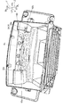
- 1 is a front view showing a head-up display device according to a first embodiment of the present invention. It is a perspective view showing the inside of the case of the head up display device concerning a 1st embodiment of the present invention.
- FIG. 2 is a perspective view showing the head-up display device with the bearing cover removed according to the first embodiment of the present invention.
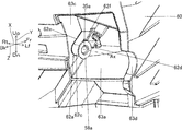
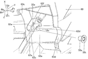
- FIG. 2 is a perspective view illustrating a bearing holding unit to which the bearing member according to the first embodiment of the present invention is attached.
- FIG. 2 is a perspective view showing the bearing holding unit before the bearing member according to the first embodiment of the present invention is mounted.
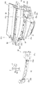
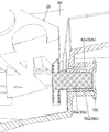
- FIG. 2 is a cross-sectional view illustrating a bearing member, a bearing holding unit, and the like according to the first embodiment of the present invention. It is a perspective view showing the concave mirror holder concerning a 1st embodiment of the present invention. It is a perspective view showing a concave mirror drive unit concerning a 1st embodiment of the present invention.
- FIG. 2 is a perspective view showing a rotating shaft and a bearing member according to the first embodiment of the present invention.
- FIG. 2 is a perspective view showing a rotating shaft and a bearing member according to the first embodiment of the present invention.
- FIG. 2 is a perspective view showing a rotating shaft and a bearing member according to the first embodiment of the present invention. It is sectional drawing which shows the rotating shaft part and bearing holding part which concern on 2nd Embodiment of this invention. It is a sectional view showing a lever part and a grip part concerning a 2nd embodiment of the present invention.
- FIG. 15 is an enlarged view of FIG. 14 according to the second embodiment of the present invention. It is sectional drawing which shows the rotating shaft part and bearing holding part which concern on 2nd Embodiment of this invention. It is a sectional view showing a lever part and a grip part concerning a 2nd embodiment of the present invention. It is sectional drawing which shows the rotating shaft part and bearing holding part which concern on 2nd Embodiment of this invention. It is a sectional view showing a lever part and a grip part concerning a 2nd embodiment of the present invention. It is sectional drawing which shows the rotating shaft part and bearing holding part which concern on 2nd Embodiment of this invention. It is a sectional
- the head-up display device 100 is installed in the dashboard of the vehicle 200.
- the head-up display device 100 emits display light L representing an image toward a windshield 201 which is an example of a projection member of the vehicle 200.
- the display light L is reflected by the windshield 201 and reaches the viewer 1 (mainly, the driver of the vehicle 200). Thereby, the virtual image V is displayed so as to be visible by the viewer 1.
- the head-up display device 100 includes a display unit 10, a folding mirror member 20, a mirror unit 30, a mirror driving unit 40, a housing 60, a control unit 70, and a control unit 70 shown in FIG.
- a bearing cover 90 and, as shown in FIG. 9, bearing members 58a and 58b.
- left and right, up and down, front and back are defined based on the direction when the concave mirror 31 of the mirror unit 30 is viewed from the front.
- the left is abbreviated as Lf
- the right is abbreviated as Rt
- the upper is abbreviated as Up
- the lower is abbreviated as Dn
- the table is abbreviated as Fr
- the back is abbreviated as Bk.
- the left-right direction matches the X direction
- the up-down direction matches the Y direction
- the front-back direction matches the Z direction.
- the display unit 10 emits display light L representing an image under the control of the control unit 70.
- the display unit 10 includes, for example, a light source and a liquid crystal display panel, both of which are not shown.
- the folding mirror member 20 is formed of, for example, a plane mirror, and reflects the display light L emitted from the display unit 10 toward the mirror unit 30.
- the folding mirror member 20 is formed by, for example, laminating aluminum on a substrate made of a resin such as polycarbonate.
- the housing 60 is formed of a non-translucent resin or metal, and has a hollow substantially rectangular parallelepiped shape.
- the housing 60 has an opening 61 at a position facing the windshield 201.
- the housing 60 includes a curved plate-shaped window 50 that closes the opening 61.
- the window portion 50 is made of a light-transmitting resin such as acrylic through which the display light L is transmitted.
- Each component of the head-up display device 100 is housed in the housing 60.
- the housing 60 has a pair of bearing holding portions 62a and 62b for receiving a pair of rotating shaft portions 35a and 35b of the concave mirror holder 35, which will be described later.
- the bearing holding portions 62a and 62b are arranged so as to be arranged in the X direction.
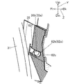
- the bearing holding portions 62 a and 62 b hold the rotating shaft portions 35 a and 35 b in the housing 60 and have a U-shaped plate shape that opens toward the window 50.
- the bearing holding portions 62a and 62b are formed in a concave shape on the inner surface of the housing 60.
- the bearing holding portions 62a and 62b are formed as concave grooves having holes passing through the inside and outside of the housing 60.
- the bearing holding portions 62a and 62b are formed in a tunnel shape connecting the inside and the outside of the housing 60.
- the bearing holding portions 62a and 62b extend along the rotating shaft portions 35a and 35b, one ends of the bearing holding portions 62a and 62b are exposed inside the housing 60, and the other ends of the bearing holding portions 62a and 62b are connected to the housing. It is exposed to the outside of 60.
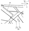
- the bearing holding portions 62a and 62b are formed so as to be exposed to the outside of the housing 60. Specifically, as shown in FIG. 7, the bearing holding portion 62a extends obliquely so as to approach the lower side as it goes back.
- the bearing holding portion 62a includes an exposed end 62d, an inner end 62e, an open end 62f, and a holding end 62c.
- the exposed end 62d is an end that is exposed while being opened to the outside of the housing 60, and is far from the holder body 34 in the X direction of the bearing holding portion 62a.
- the exposed end 62d is exposed while being opened to the outside of the housing 60, so that the bearing member 58a can be pressed into the bearing holding portion 62a from the exposed end 62d.
- the inner end 62e is located on the side opposite to the exposed end 62d in the X direction.
- the inner end 62e is an end of the bearing holding portion 62a close to the holder body 34, and opens toward the holder body 34 located in the internal space of the housing 60.
- the opening end 62 f opens upward and to the front side toward the internal space of the housing 60.
- the rotating shaft 35a is inserted into the opening end 62f when the mirror unit 30 is assembled to the housing 60.
- the holding end 62c is located on the opposite side to the opening end 62f in the Y direction, and is formed in a substantially C-shaped plate along the outer periphery of the bearing member 58a so as to grip the bearing member 58a.
- the bearing holding portion 62b is configured similarly to the bearing holding portion 62a.
- housing recesses 63 a and 63 b for housing the bearing holding portions 62 a and 62 b are formed on the outer surface of the housing 60.
- the housing recesses 63a and 63b form a rectangular parallelepiped, and the bearing holding portions 62a and 62b are located on the side surfaces 63c near the center of the head-up display device 100 in the X direction in the housing recesses 63a and 63b.
- a jig recess 63d is formed on a side wall of the housing recesses 63a and 63b facing the side surface 63c in the X direction.
- the jig concave portion 63d is located opposite to the bearing holding portions 62a, 62b in the X direction, and a jig (not shown) used for press-fitting the bearing members 58a, 58b into the bearing holding portions 62a, 62b passes therethrough. Formed for
- the mirror unit 30 includes a concave mirror 31 that is an example of a reflecting mirror that reflects the display light L, and a concave mirror holder 35 that holds the concave mirror 31.
- the concave mirror 31 is formed in a substantially rectangular plate shape that is long in the X direction, and is curved along the X direction.
- the concave mirror 31 has a mirror surface 31a formed on the front side of the concave mirror 31 and reflecting light.
- the concave mirror 31 is formed by depositing a metal reflecting material such as aluminum on a synthetic resin base material having a concave curved surface.
- the concave mirror 31 reflects the display light L reflected by the mirror member 20 on the mirror surface 31 a while expanding the display light L toward the windshield 201.
- the concave mirror 31 is configured to be rotatable together with the concave mirror holder 35 around a rotation axis Ax extending in a direction perpendicular to the plane of FIG.
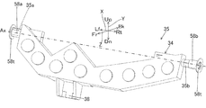
- the concave mirror holder 35 is formed of resin, and holds the concave mirror 31 from the back. As shown in FIG. 4, the concave mirror holder 35 is supported in the housing 60 so as to be rotatable about a rotation axis Ax. More specifically, as shown in FIG. 9, the concave mirror holder 35 includes a holder body 34, rotation shafts 35 a and 35 b, and a lever 38.
- the holder body 34 has a plate shape having a curved surface along the back surface of the concave mirror 31.
- the rotation shaft portions 35a and 35b are located on the right side surface and the left side surface of the holder main body 34, and have a columnar shape extending along the rotation axis Ax.
- the rotating shaft 35a has a protrusion 34c on the peripheral surface of the rotating shaft 35a.
- the protrusion 34c is formed in a convex shape on the peripheral surface of the rotation shaft 35a.
- the protrusion 34c has a substantially triangular pyramid shape. That is, the protrusion 34c is formed so that its height becomes lower with reference to the circumferential surface as it goes toward the tip of the rotation shaft 35a, and the height increases as the distance from the center of the protrusion 34c in the circumferential direction of the rotation shaft 35a increases. Is formed to be lower with respect to the peripheral surface.
- the rotating shaft 35b is configured similarly to the rotating shaft 35a.
- the lever portion 38 is located at the center of the lower surface of the holder main body portion 34 and extends downward. As shown in FIG. 10, an external force is applied to the lever 38 from a concave mirror driving unit 71 described later. Thereby, the concave mirror holder 35 rotates together with the concave mirror 31 about the rotation axis Ax.
- the pair of bearing members 58a and 58b each have a cylindrical shape press-fitted into the rotating shaft portions 35a and 35b, and are held by the bearing holding portions 62a and 62b. , 35b and thus the concave mirror holder 35 are rotatably supported.
- Each of the bearing members 58a and 58b has a flange 58t that extends radially outward of the bearing members 58a and 58b at one end.
- the bearing members 58a and 58b are, for example, sliding bearings in which a plate material is wound in a cylindrical shape.
- the sheet material is a 0.25 mm thick electrogalvanized steel sheet (SECC), a copper wire mesh as a reinforcing material disposed on the back metal of the electrogalvanized steel sheet, and a polytetrafluoroethylene (PET) covering the wire mesh.
- SECC electrogalvanized steel sheet
- PET polytetrafluoroethylene
- This plate is 0.75 mm thick, for example.
- the bearing members 58a and 58b are not limited to sliding bearings, but may be ball bearings.
- a temporary fixing hole 58c, a rotation permitting hole 58d, a slit 58f, and a gate 58e are formed in the bearing member 58a.
- the temporary fixing hole 58c penetrates in the thickness direction of the bearing member 58a, and forms a rectangle that is long in the circumferential direction of the bearing member 58a.
- the temporary fixing hole 58c is located adjacent to the rotation allowing hole 58d along the rotation axis Ax, and is formed at a position closer to the holder main body 34 than the rotation allowing hole 58d. As shown in FIG.
- the protrusion 34c of the rotating shaft 35a is located in the temporary fixing hole 58c.
- the bearing member 58a is temporarily fixed to the rotating shaft portion 35a.
- the rotation permitting hole 58d penetrates in the thickness direction of the bearing member 58a and forms a rectangle longer in the circumferential direction of the bearing member 58a than the temporary fixing hole 58c.
- the rotation permissible hole 58d is set to have a length corresponding to the rotation range of the concave mirror holder 35 in the circumferential direction. As shown in FIG.
- the gate portion 58e includes a pair of rod portions formed between the temporary fixing hole 58c and the rotation allowing hole 58d so as to partition the temporary fixing hole 58c and the rotation allowing hole 58d, and extending in the circumferential direction of the bearing member 58a.
- the gap between the pair of rods is formed so that the protrusion 34c of the rotating shaft 35a can pass through.
- the slit 58f extends from the temporary fixing hole 58c to an end surface of the bearing member 58a near the holder main body 34.
- the slit 58f is formed so that the protrusion 34c of the rotating shaft 35a can pass therethrough.
- the bearing member 58b is configured similarly to the bearing member 58a.
- the bearing cover 90 is attached to the outer surface of the housing 60 so as to hide the bearing holding portions 62a and 62b from the outside.
- the bearing cover 90 includes a pair of cover portions 91a and 91b, and a connecting portion 92 that connects between the cover portions 91a and 91b.
- the pair of cover portions 91a and 91b have a rectangular plate shape corresponding to the opening edges of the housing recesses 63a and 63b, respectively.
- the cover 91a closes the housing recess 63a, and the cover 91b closes the housing recess 63b.
- the covers 91a and 91b are fixed by screwing a screw 98 (see FIG. 3) to a column 99 (see FIG. 5) provided on the bottom surface of the housing recesses 63a and 63b.
- the connecting portion 92 has a rectangular plate shape extending in the X direction between the cover portions 91a and 91b.
- the connecting portion 92 is fixed to the housing 60 by screwing a screw 98 between the pair of housing recesses 63a and 63b on the outer surface of the housing 60.
- the connecting portion 92 includes a pair of elastic portions 93a and 93b at portions connected to the cover portions 91a and 91b.
- Each of the pair of elastic portions 93a and 93b has two S-shapes arranged along the Y direction.
- One ends of the S-shaped elastic portions 93a and 93b are connected to the cover portions 91a and 91b, and the other ends of the S-shaped portions are connected to the main body of the connecting portion 92.
- the elastic portions 93a and 93b elastically deform so as to allow a change in the positional relationship between the cover portions 91a and 91b.
- the elastic portions 93a and 93b make it easy to mount the bearing cover 90 on the housing 60 regardless of the shape error of the bearing cover 90 or the housing 60.
- the concave mirror driving unit 71 rotates the mirror unit 30 about the rotation axis Ax.
- the concave mirror driving unit 71 includes a motor 72 and a conversion mechanism 73.
- the motor 72 is fixed in the housing 60 and is driven under the control of the control unit 70.
- the conversion mechanism 73 is a mechanism that converts the rotational movement of the motor 72 into a linear movement. More specifically, the conversion mechanism 73 includes a screw shaft 73a whose outer periphery is threaded, and a grip portion 73b penetrated by the screw shaft 73a.
- the grip 73b includes a contact projection 73e with which the lever 38 contacts, and a clip 73d that pushes the lever 38 toward the contact projection 73e.
- the clip portion 73d is formed by bending a metal plate material into a V-shape.
- the tip of the clip portion 73d is positioned so as to face the clip portion 73d in the Z direction.
- the contact convex portion 73e has a hemispherical shape protruding toward the lever portion 38, and sandwiches the lever portion 38 together with the clip portion 73d.
- the grip portion 73b moves along the screw shaft 73a as the screw shaft 73a rotates with the driving of the motor 72.
- the motor 72 and the conversion mechanism 73 rotate the concave mirror holder 35 about the rotation axis Ax via the lever portion 38.
- the control unit 70 includes a CPU (Central Processing Unit), a ROM (Read Only Memory), a RAM (Random Access Memory), and the like, and controls the display unit 10 and the motor 72.
- the control unit 70 rotates the mirror unit 30 by driving the mower 72.
- the rotating shaft portions 35a and 35b of the mirror unit 30 are inserted into the bearing holding portions 62a and 62b.
- the bearing members 58a and 58b are not mounted on the rotating shaft portions 35a and 35b. Therefore, the rotating shaft portions 35a and 35b can be easily inserted into the bearing holding portions 62a and 62b.
- the bearing member 58a is pressed into the bearing holding portion 62a so as to be inserted into the rotary shaft portion 35a. As described above, the bearing holding portion 62a is exposed to the outside.
- the bearing member 58a can be pressed into the holding end 62c of the bearing holding portion 62b from the exposed end 62d of the bearing holding portion 62b.
- the bearing member 58b is pressed into the bearing holding portion 62b so as to be inserted into the rotating shaft portion 35b.
- the bearing members 58a and 58b rotatably support the rotating shaft portions 35a and 35b of the concave mirror holder 35 while being held in the bearing holding portions 62a and 62b.
- the press-fitting operation of the bearing member 58a into the rotating shaft portion 35a is performed by an operator using, for example, a jig (not shown) for pushing the bearing member 58a into the rotating shaft portion 35a.
- a jig not shown
- the bearing member 58a is moved closer to the tip of the rotating shaft 35a so that the slit 58f approaches the protrusion 34c.
- the protrusion portion 34c passes through the slit 58f and reaches the inside of the temporary fixing hole 58c.
- the bearing member 58a is temporarily fixed to the rotating shaft portion 35a. Further, when the bearing member 58a is pushed toward the rotation shaft portion 35a, as shown in FIG. 13, the protrusion portion 34c passes through the gap of the gate portion 58e and reaches the inside of the rotation permitting hole 58d. At this time, the protrusion 34c is movable along the circumferential direction of the bearing member 58a in the rotation permitting hole 58d. Therefore, the bearing member 58a can rotatably support the rotating shaft portion 35a in a state where the bearing member 58a is prevented from falling off from the rotating shaft portion 35a. The manner of press-fitting the bearing member 58b into the rotating shaft 35b is also the same.
- the head-up display device 100 includes a display unit 10 that emits display light L, a mirror unit 30 that reflects the display light L from the display unit 10 to a front glass 201 that is an example of a projection target member, and a mirror unit.
- the mirror unit 30 includes a concave mirror 31 including a mirror surface 31a that reflects the display light L, a holder main body 34 that holds the concave mirror 31, and a rotation axis Ax, and is rotatably supported by bearing members 58a and 58b.
- a concave mirror holder 35 which is an example of a reflecting mirror holder having rotating shaft portions 35a and 35b.
- the housing 60 includes bearing holding portions 62a and 62b formed in a concave shape on the inner surface of the housing 60 so as to hold the bearing members 58a and 58b.
- the bearing holding portions 62a and 62b are located at ends far from the holder main body 34 in the X direction along the rotation axis Ax, and are exposed when the bearing members 58a and 58b are opened to the outside of the housing 60 so as to be press-fittable. An end 62d is provided. According to this configuration, the bearing members 58a and 58b can be pressed into the bearing holding portions 62a and 62b from outside the housing 60. Therefore, the mounting of the bearing members 58a and 58b to the housing 60 becomes easy.
- the bearing holding portions 62a and 62b are formed in a U-shaped plate opening toward the internal space of the housing 60. According to this configuration, the rotating shaft portions 35a and 35b are inserted into the bearing holding portions 62a and 62b from the internal space of the housing 60, and then the bearing members 58a and 58b are inserted by the rotating shaft portions 35a and 35b. So as to be pressed into the bearing holding portions 62a and 62b. Therefore, the mirror unit 30 can be easily attached to the housing 60.
- accommodation recesses 63a, 63b for accommodating the bearing holding portions 62a, 62b are formed. According to this configuration, a space for press-fitting the bearing members 58a, 58b into the bearing holding portions 62a, 62b is secured by the housing recesses 63a, 63b. Therefore, the work of press-fitting the bearing members 58a and 58b becomes easy.
- a bearing cover 90 that covers the housing recesses 63a and 63b is attached to the outer surface of the housing 60. According to this configuration, the bearing members 58a and 58b are hidden by the bearing cover 90. Therefore, for example, when assembling the head-up display device 100 to the vehicle 200, foreign substances are suppressed from contacting the bearing members 58a and 58b. In addition, entry of dust or moisture into the housing 60 is suppressed.
- the bearing holding portion 62b has a convex portion 62b1 at the opening end 62f on the opening side.
- the protrusion 62b1 is located below the opening end 62f and protrudes upward.
- the convex portion 62b1 is formed so as to define the entrance width W of the bearing holding portion 62b.
- the rotating shaft 35b has a flat surface 35b1 on a part of the outer peripheral surface of the rotating shaft 35b. By forming the flat surface 35b1, the rotating shaft 35b has a minimum diameter ⁇ 1 and a maximum diameter ⁇ 2.
- the minimum diameter ⁇ 1 is the minimum diameter among the diameters of the rotating shaft 35b extending in the direction passing through the plane 35b1.
- the maximum diameter ⁇ 2 is the diameter of the rotating shaft 35b extending in a direction not passing through the plane 35b1, and matches the diameter of the rotating shaft 35b when the plane 35b1 is not formed.
- the maximum diameter ⁇ 2 is set larger than the entrance width W, and the minimum diameter ⁇ 1 is set smaller than the entrance width W.
- the rotating shaft portion 35b can be inserted into the bearing holding portion 62b in a direction in which the minimum diameter ⁇ 1 is in the same direction as the inlet width W.
- the bearing holding part 62b and the rotating shaft part 35b not only the bearing holding part 62b and the rotating shaft part 35b, but also the bearing holding part 62a and the rotating shaft part 35a have the convex part 62a1 and the flat surface 35a1 like the bearing holding part 62b and the rotating shaft part 35b.
- the bearing holding parts 62a and 62b are located at the opening end 62f on the opening side of the bearing holding parts 62a and 62b, and include a convex part 62b1 that defines the entrance width W of the bearing holding parts 62a and 62b.
- the rotating shaft portions 35a and 35b extend in a direction different from the maximum diameter ⁇ 2, which is an example of a first diameter larger than the entrance width W of the bearing holding portions 62a and 62b, and the maximum diameter ⁇ 2, and extend in the bearing holding portions 62a and 62b. It is formed so as to have a minimum diameter ⁇ 1, which is an example of a second diameter smaller than the inlet width W.
- the concave mirror holder 35 has a lever portion 38.
- the concave mirror drive unit 71 includes a grip portion 73b that grips the lever portion 38.
- the lever portion 38 is formed so that when the rotating shaft portions 35a and 35b are inserted into the bearing holding portions 62a and 62b with the minimum diameter ⁇ 1 along the inlet width W, the grip portion 73b grips the lever portion 38.
- the posture of the concave mirror holder 35 when inserting the rotating shaft portions 35a and 35b into the bearing holding portions 62a and 62b is defined. Thereby, when the insertion of the rotary shaft portions 35a, 35b into the bearing holding portions 62a, 62b is completed, the lever portion 38 of the concave mirror holder 35 is naturally gripped by the grip portion 73b.
- the mirror unit 30 can be more easily assembled to the housing 60.
- the protrusion 62a1 can also prevent the bearing members 58a, 58b mounted on the bearing holding portions 62a, 62b from jumping out of the opening end 62f.
- the bearing members 58a and 58b are mounted on the pair of rotating shaft portions 35a and 35b of the concave mirror holder 35, respectively, but one of the bearing members 58a and 58b may be omitted.
- the rotating shaft 35b may be directly supported by the bearing holding part 62b.
- the bearing holding portion 62b may be formed so as not to be exposed to the outside.
- the cover portion 91b of the bearing cover 90 may be omitted.
- the bearing members 58a and 58b are formed with the temporary fixing holes 58c, the rotation permitting holes 58d, the slits 58f, and the gate portions 58e. However, all of these may be omitted or the temporary fixing may be performed. Only the hole 58c and the gate 58e may be omitted.
- the connecting portion 92 of the bearing cover 90 in each of the above embodiments may be omitted.
- the pair of cover portions 91a and 91b are configured separately.
- the configuration of the head-up display device 100 in each of the above embodiments can be changed as appropriate.
- the display light L from the display unit 10 may be directly applied to the mirror unit 30 by omitting the folding mirror member 20.
- the head-up display device 100 may include a plane mirror instead of the concave mirror 31.
- the elastic portions 93a and 93b are formed in two S-shapes arranged in the Y direction. There may be.
- the accommodation recesses 63a and 63b in each of the above embodiments can be omitted.
- the bearing holding portions 62a and 62b may protrude from the outer surface of the housing 60.
- the cover portions 91a and 91b may be formed in a box shape surrounding the bearing holding portions 62a and 62b.
- the head-up display device 100 is mounted on the vehicle 200; however, the head-up display device 100 may be mounted on vehicles other than the vehicle 200, such as airplanes and ships. Further, the projection member is not limited to the windshield, and may be a dedicated combiner.
- the flat surface 35b1 is formed on the rotating shaft 35b, so that the rotating shaft 35b has the minimum diameter ⁇ 1 and the maximum diameter ⁇ 2.
- the rotating shaft portion 35b may have a minimum diameter ⁇ 1 and a maximum diameter ⁇ 2.
- the bearing holding portions 62a and 62b are formed so as to be entirely exposed to the outside of the housing 60. However, only the exposed end 62d of the bearing holding portions 62a and 62b is formed.
- the bearing members 58a and 58b may be exposed to the outside so as to be press-fitted, and a portion other than the exposed end 62d may be hidden from the outside. Further, the bearing holding portions 62 a and 62 b may be formed so as not to be exposed to the outside of the housing 60.
- the head-up display device 100 can also solve the problems in other viewpoints.
- This problem will be described.
- Conventionally when assembling the mirror unit inside the housing, it has been necessary to adjust the orientation of the mirror unit so that the lever portion of the reflector holder is gripped by the gripper of the reflector drive unit.
- the positions of the lever and the grip are difficult to see due to the mirror surface, and it has been difficult to correctly insert the lever into the grip in this situation.
- the following supplementary notes 1 and 2 have been made in view of the above situation, and an object thereof is to provide a head-up display device that makes it easy to correctly assemble a mirror unit to a housing. This problem can be solved, for example, by the following supplementary notes 1 and 2.
- the bearing holding portion is provided at an end on the opening side of the bearing holding portion, and includes a convex portion that defines an entrance width of the bearing holding portion,
- the rotating shaft portion extends in a first direction larger than the entrance width of the bearing holding portion and a direction different from the first direction, and has a second diameter smaller than the entrance width of the bearing holding portion.
- Head-up display device Formed to have, Head-up display device.
- the head-up display device includes a reflecting mirror driving unit that rotates the mirror unit around the rotation axis,
- the reflecting mirror holder includes a lever portion,
- the reflecting mirror drive unit includes a grip portion that grips the lever portion,
- the lever portion is formed such that when the rotation shaft portion is inserted into the bearing holding portion in a direction in which the second diameter is along the entrance width, the grip portion is gripped by the grip portion.
Landscapes
- Engineering & Computer Science (AREA)
- Mechanical Engineering (AREA)
- Chemical & Material Sciences (AREA)
- Combustion & Propulsion (AREA)
- Transportation (AREA)
- Physics & Mathematics (AREA)
- General Physics & Mathematics (AREA)
- Optics & Photonics (AREA)
- Instrument Panels (AREA)
Abstract
軸受け部材の筐体への組み付けが容易となるヘッドアップディスプレイ装置を提供する。 ヘッドアップディスプレイ装置は、表示光を出射する表示部と、表示部からの表示光をフロントガラスに向けて反射させるミラーユニットと、ミラーユニットを収容する筐体60と、ミラーユニットを回転可能に支持する軸受け部材58aと、を備える。ミラーユニットは、表示光を反射する鏡面を含む凹面鏡と、凹面鏡を保持するホルダ本体部、及び回転軸Axに沿って延び、軸受け部材58aにより回転可能に支持される回転軸部35aを有する凹面鏡ホルダと、を備える。筐体60は、軸受け部材58aを保持するように筐体60の内面に凹状に形成される軸受け保持部62aを備える。軸受け保持部62aは、回転軸Axに沿うX方向におけるホルダ本体部から遠い端部に位置し、筐体60の外部に開口した状態で露出する露出端部62dを備える。
Description
本発明は、ヘッドアップディスプレイ装置に関する。
従来から、表示光をフロントガラス等に照射することにより虚像を表示するヘッドアップディスプレイ装置が知られている。例えば、特許文献1に記載のヘッドアップディスプレイ装置は、表示光を反射させる凹面鏡と、凹面鏡を保持するホルダと、ホルダの回転軸を回転可能に支持するベアリング(軸受け部材)と、ベアリングを筐体の所定位置に保持するベアリング保持部と、を備える。
本願発明者らは、ベアリング保持部を筐体と一体で形成することを検討している。しかしながら、この構成では、ベアリングをベアリング保持部に圧入する際、ベアリングを筐体の内面に押し込む必要があるため、組み付け作業が困難であった。
本発明は、上記実状を鑑みてなされたものであり、軸受け部材の筐体への組み付けが容易となるヘッドアップディスプレイ装置を提供することを目的とする。
上記目的を達成するため、本発明の観点に係るヘッドアップディスプレイ装置は、表示光を出射する表示部と、前記表示部からの前記表示光を被投射部材に向けて反射させるミラーユニットと、前記ミラーユニットを収容する筐体と、前記ミラーユニットを回転軸を中心に回転可能に支持する軸受け部材と、を備え、前記ミラーユニットは、前記表示光を反射する鏡面を含む反射鏡と、前記反射鏡を保持するホルダ本体部、及び前記回転軸に沿って延び、前記軸受け部材により回転可能に支持される回転軸部を有する反射鏡ホルダと、を備え、前記筐体は、前記軸受け部材を保持するように前記筐体の内面に凹状に形成される軸受け保持部を備え、前記軸受け保持部は、前記回転軸に沿う方向における前記ホルダ本体部から遠い端部に位置し、前記筐体の外部に開口した状態で露出する露出端部を備える。
本発明によれば、ヘッドアップディスプレイ装置において、軸受け部材の筐体への組み付けが容易となる。
(第1の実施形態)
本発明に係るヘッドアップディスプレイ装置の第1の実施形態について、図面を参照して説明する。
本発明に係るヘッドアップディスプレイ装置の第1の実施形態について、図面を参照して説明する。
図1に示すように、ヘッドアップディスプレイ装置100は、車両200のダッシュボード内に設置される。ヘッドアップディスプレイ装置100は、車両200の被投射部材の一例であるフロントガラス201に向けて像を表す表示光Lを出射する。表示光Lはフロントガラス201で反射して視認者1(主に車両200の運転者)に到達する。これにより、虚像Vが視認者1により視認可能に表示される。
ヘッドアップディスプレイ装置100は、図2に示すように、表示部10と、折り返しミラー部材20と、ミラーユニット30と、ミラー駆動ユニット40と、筐体60と、制御部70と、図3に示すように、軸受けカバー90と、図9に示すように、軸受け部材58a,58bと、を備える。
なお、以下の説明では、ミラーユニット30の凹面鏡31を正面から見たときの方向に基づき、左右、上下、表裏が規定されている。図3~図20においては、左はLfと略記され、右はRtと略記され、上はUpと略記され、下はDnと略記され、表はFrと略記され、裏はBkと略記される。また、左右方向はX方向と一致し、上下方向はY方向と一致し、表裏方向はZ方向に一致する。
なお、以下の説明では、ミラーユニット30の凹面鏡31を正面から見たときの方向に基づき、左右、上下、表裏が規定されている。図3~図20においては、左はLfと略記され、右はRtと略記され、上はUpと略記され、下はDnと略記され、表はFrと略記され、裏はBkと略記される。また、左右方向はX方向と一致し、上下方向はY方向と一致し、表裏方向はZ方向に一致する。
図2に示すように、表示部10は、制御部70による制御のもと、像を表す表示光Lを出射する。表示部10は、例えば、何れも図示しない光源及び液晶表示パネルを備える。
折り返しミラー部材20は、例えば平面鏡からなり、表示部10が出射した表示光Lをミラーユニット30に向けて反射させる。折り返しミラー部材20は、例えば、ポリカーボネート等の樹脂からなる基材にアルミニウムが積層されてなる。
筐体60は、非透光性の樹脂又は金属で形成されるとともに、中空の略直方体をなす。筐体60には、フロントガラス201に対向する位置に開口部61が形成されている。筐体60は、開口部61を塞ぐ湾曲板状の窓部50を備える。この窓部50は、表示光Lが透過するアクリル等の透光性の樹脂からなる。筐体60内には、ヘッドアップディスプレイ装置100の各構成が収納されている。
図4に示すように、筐体60は、凹面鏡ホルダ35の後述する一対の回転軸部35a,35bを受ける一対の軸受け保持部62a,62bを有する。軸受け保持部62a,62bは、X方向に沿って並ぶように配置される。軸受け保持部62a,62bは、筐体60内に回転軸部35a,35bを保持し、窓部50に向けて開口するU字板状をなす。軸受け保持部62a,62bは、筐体60の内面に凹状に形成される。図8に示すように、軸受け保持部62a,62bは、筐体60の内外を貫通する穴を有する凹状の溝として形成されている。言い換えると、軸受け保持部62a,62bは、筐体60の内部と外部を繋ぐトンネル状に形成される。また、軸受け保持部62a,62bは回転軸部35a,35bに沿って延び、軸受け保持部62a,62bの一端は筐体60の内部に露出し、軸受け保持部62a,62bの他端は筐体60の外部に露出する。
図5に示すように、軸受け保持部62a,62bは、筐体60の外部に露出するように形成される。
詳しくは、図7に示すように、軸受け保持部62aは、裏側に向かうにつれて下側に近づくように斜めに延びる。
軸受け保持部62aは、露出端部62dと、内端部62eと、開口端部62fと、保持端部62cと、を備える。
露出端部62dは、筐体60の外部に開口しつつ露出し、軸受け保持部62aにおけるX方向においてホルダ本体部34から遠い端部である。露出端部62dが筐体60の外部に開口しつつ露出することにより、露出端部62dから軸受け部材58aが軸受け保持部62a内に圧入可能となる。
また、内端部62eは、X方向において露出端部62dと反対側に位置する。内端部62eは、軸受け保持部62aにおけるホルダ本体部34に近い端部であり、筐体60の内部空間に位置するホルダ本体部34に向かって開口する。
また、開口端部62fは、筐体60の内部空間に向けて上側及び表側へ開口する。開口端部62fには、ミラーユニット30を筐体60に組み付ける際に回転軸部35aが挿入される。
また、保持端部62cは、Y方向において開口端部62fと反対側に位置し、軸受け部材58aを把持するように軸受け部材58aの外周に沿う略C字板状に形成される。
なお、軸受け保持部62bは軸受け保持部62aと同様に構成される。
詳しくは、図7に示すように、軸受け保持部62aは、裏側に向かうにつれて下側に近づくように斜めに延びる。
軸受け保持部62aは、露出端部62dと、内端部62eと、開口端部62fと、保持端部62cと、を備える。
露出端部62dは、筐体60の外部に開口しつつ露出し、軸受け保持部62aにおけるX方向においてホルダ本体部34から遠い端部である。露出端部62dが筐体60の外部に開口しつつ露出することにより、露出端部62dから軸受け部材58aが軸受け保持部62a内に圧入可能となる。
また、内端部62eは、X方向において露出端部62dと反対側に位置する。内端部62eは、軸受け保持部62aにおけるホルダ本体部34に近い端部であり、筐体60の内部空間に位置するホルダ本体部34に向かって開口する。
また、開口端部62fは、筐体60の内部空間に向けて上側及び表側へ開口する。開口端部62fには、ミラーユニット30を筐体60に組み付ける際に回転軸部35aが挿入される。
また、保持端部62cは、Y方向において開口端部62fと反対側に位置し、軸受け部材58aを把持するように軸受け部材58aの外周に沿う略C字板状に形成される。
なお、軸受け保持部62bは軸受け保持部62aと同様に構成される。
図5及び図6に示すように、筐体60の外面には、軸受け保持部62a,62bを収容する収容凹部63a,63bが形成される。
収容凹部63a,63bは直方体をなし、軸受け保持部62a,62bは、収容凹部63a,63bにおけるX方向のヘッドアップディスプレイ装置100の中央に近い側面63cに位置する。
収容凹部63a,63bにおける側面63cにX方向に対向する側壁には、治具用凹部63dが形成される。治具用凹部63dは、軸受け保持部62a,62bとX方向に対向して位置し、軸受け保持部62a,62bに軸受け部材58a,58bを圧入する際に使用される図示しない治具が通過するために形成される。
収容凹部63a,63bは直方体をなし、軸受け保持部62a,62bは、収容凹部63a,63bにおけるX方向のヘッドアップディスプレイ装置100の中央に近い側面63cに位置する。
収容凹部63a,63bにおける側面63cにX方向に対向する側壁には、治具用凹部63dが形成される。治具用凹部63dは、軸受け保持部62a,62bとX方向に対向して位置し、軸受け保持部62a,62bに軸受け部材58a,58bを圧入する際に使用される図示しない治具が通過するために形成される。
図2に示すように、ミラーユニット30は、表示光Lを反射させる反射鏡の一例である凹面鏡31と、凹面鏡31を保持する凹面鏡ホルダ35と、を備える。
凹面鏡31は、X方向に長い略長方形の板状に形成され、X方向に沿って湾曲している。凹面鏡31は、凹面鏡31の表側に形成され光を反射させる鏡面31aを備える。凹面鏡31は、凹状の曲面を有する合成樹脂製の基材にアルミニウム等の金属製の反射材が蒸着されることにより形成される。凹面鏡31は、鏡面31aにて折り返しミラー部材20で反射した表示光Lをフロントガラス201に向けて拡大させつつ反射させる。また、凹面鏡31は、凹面鏡ホルダ35とともに、図2の紙面垂直方向に延びる回転軸Axを中心に回転可能に構成されている。
凹面鏡ホルダ35は、樹脂により形成され、凹面鏡31をその裏面から保持する。図4に示すように、凹面鏡ホルダ35は、筐体60内で回転軸Axを中心に回転可能に支持される。
詳しくは、図9に示すように、凹面鏡ホルダ35は、ホルダ本体部34と、回転軸部35a,35bと、レバー部38と、を備える。
ホルダ本体部34は、凹面鏡31の裏面に沿う曲面を有する板状をなす。回転軸部35a,35bは、ホルダ本体部34の右側側面と左側側面に位置し、回転軸Axに沿って延びる円柱状をなす。
詳しくは、図9に示すように、凹面鏡ホルダ35は、ホルダ本体部34と、回転軸部35a,35bと、レバー部38と、を備える。
ホルダ本体部34は、凹面鏡31の裏面に沿う曲面を有する板状をなす。回転軸部35a,35bは、ホルダ本体部34の右側側面と左側側面に位置し、回転軸Axに沿って延びる円柱状をなす。
図13に示すように、回転軸部35aは、回転軸部35aの周面に突起部34cを有する。突起部34cは、回転軸部35aの周面に凸状に形成される。突起部34cは、略三角錐状をなす。すなわち、突起部34cは、回転軸部35aの先端に向かうにつれて周面を基準として高さが低くなるように形成され、かつ、回転軸部35aの周方向において突起部34cの中心から離れるにつれて高さが周面を基準として低くなるように形成される。回転軸部35bも回転軸部35aと同様に構成される。
図9に示すように、レバー部38は、ホルダ本体部34の下面の中央に位置し、下方向に延びる。レバー部38は、図10に示すように、後述する凹面鏡駆動ユニット71から外力が加えられる。これにより、凹面鏡ホルダ35は回転軸Axを中心に凹面鏡31とともに回転する。
図9に示すように、一対の軸受け部材58a,58bは、それぞれ、回転軸部35a,35bに圧入される円筒状をなし、軸受け保持部62a,62bにより保持された状態で、回転軸部35a,35b、ひいては凹面鏡ホルダ35を回転可能に支持する。軸受け部材58a,58bは、その一端に軸受け部材58a,58bの径方向外側に延びる鍔部58tを有する。
軸受け部材58a,58bは、例えば、板材が円筒状に巻かれた滑り軸受けである。この板材は、厚さ0.25mmの電気亜鉛メッキ鋼板(SECC)と、電気亜鉛メッキ鋼板の裏金上に配置される強化材料としての銅製のワイヤーメッシュと、このワイヤーメッシュを覆うポリテトラフルオロエチレン(PTFE)からなるオーバーレイ層と、を備える。この板材は、例えば、厚さ0.75mmである。
なお、軸受け部材58a,58bは、滑り軸受けに限らず、ボールベアリングであってもよい。
軸受け部材58a,58bは、例えば、板材が円筒状に巻かれた滑り軸受けである。この板材は、厚さ0.25mmの電気亜鉛メッキ鋼板(SECC)と、電気亜鉛メッキ鋼板の裏金上に配置される強化材料としての銅製のワイヤーメッシュと、このワイヤーメッシュを覆うポリテトラフルオロエチレン(PTFE)からなるオーバーレイ層と、を備える。この板材は、例えば、厚さ0.75mmである。
なお、軸受け部材58a,58bは、滑り軸受けに限らず、ボールベアリングであってもよい。
図13に示すように、軸受け部材58aには、仮止め孔58c、回転許容孔58d、スリット58f及びゲート部58eが形成される。
仮止め孔58cは、軸受け部材58aの厚さ方向に貫通し、軸受け部材58aの周方向に長い長方形をなす。仮止め孔58cは、回転軸Axに沿って回転許容孔58dの隣りに位置し、回転許容孔58dよりもホルダ本体部34に近い位置に形成される。
図12に示すように、軸受け部材58aが回転軸部35aに装着される過程において、仮止め孔58c内には、回転軸部35aの突起部34cが位置する。これにより、軸受け部材58aは回転軸部35aに仮止めされる。
回転許容孔58dは、軸受け部材58aの厚さ方向に貫通し、仮止め孔58cよりも軸受け部材58aの周方向に長い長方形をなす。回転許容孔58dは、周方向において凹面鏡ホルダ35の回転範囲に応じた長さに設定されている。図13に示すように、軸受け部材58aが回転軸部35aに装着されたとき、回転許容孔58d内には、回転軸部35aの突起部34cが位置する。凹面鏡ホルダ35が回転すると、突起部34cは回転許容孔58d内を移動する。このように、軸受け部材58aは、回転軸部35aを回転可能に支持する。
仮止め孔58cは、軸受け部材58aの厚さ方向に貫通し、軸受け部材58aの周方向に長い長方形をなす。仮止め孔58cは、回転軸Axに沿って回転許容孔58dの隣りに位置し、回転許容孔58dよりもホルダ本体部34に近い位置に形成される。
図12に示すように、軸受け部材58aが回転軸部35aに装着される過程において、仮止め孔58c内には、回転軸部35aの突起部34cが位置する。これにより、軸受け部材58aは回転軸部35aに仮止めされる。
回転許容孔58dは、軸受け部材58aの厚さ方向に貫通し、仮止め孔58cよりも軸受け部材58aの周方向に長い長方形をなす。回転許容孔58dは、周方向において凹面鏡ホルダ35の回転範囲に応じた長さに設定されている。図13に示すように、軸受け部材58aが回転軸部35aに装着されたとき、回転許容孔58d内には、回転軸部35aの突起部34cが位置する。凹面鏡ホルダ35が回転すると、突起部34cは回転許容孔58d内を移動する。このように、軸受け部材58aは、回転軸部35aを回転可能に支持する。
ゲート部58eは、仮止め孔58cと回転許容孔58dを仕切るように、仮止め孔58cと回転許容孔58dの間に形成され、軸受け部材58aの周方向に延びる一対の棒状部を備える。この一対の棒状部の間の隙間は、回転軸部35aの突起部34cが通過可能に形成されている。
スリット58fは、仮止め孔58cから軸受け部材58aにおけるホルダ本体部34に近い端面まで延びる。スリット58fは、回転軸部35aの突起部34cが通過可能に形成されている。
軸受け部材58bも軸受け部材58aと同様に構成される。
スリット58fは、仮止め孔58cから軸受け部材58aにおけるホルダ本体部34に近い端面まで延びる。スリット58fは、回転軸部35aの突起部34cが通過可能に形成されている。
軸受け部材58bも軸受け部材58aと同様に構成される。
図3及び図5に示すように、軸受けカバー90は、軸受け保持部62a,62bを外部から隠すように筐体60の外面に取り付けられる。軸受けカバー90は、一対のカバー部91a,91bと、カバー部91a,91bの間を連結する連結部92と、を備える。
一対のカバー部91a,91bは、それぞれ収容凹部63a,63bの開口縁に対応する長方形の板状をなす。カバー部91aは収容凹部63aを塞ぎ、カバー部91bは収容凹部63bを塞ぐ。カバー部91a,91bは、収容凹部63a,63bの底面に設けられる円柱部99(図5参照)にねじ98(図3参照)が螺合されることにより固定される。
一対のカバー部91a,91bは、それぞれ収容凹部63a,63bの開口縁に対応する長方形の板状をなす。カバー部91aは収容凹部63aを塞ぎ、カバー部91bは収容凹部63bを塞ぐ。カバー部91a,91bは、収容凹部63a,63bの底面に設けられる円柱部99(図5参照)にねじ98(図3参照)が螺合されることにより固定される。
連結部92は、カバー部91a,91bの間にX方向に延びる長方形板状をなす。連結部92は、筐体60の外面における一対の収容凹部63a,63bの間にねじ98が螺合されることにより筐体60に固定される。
また、連結部92は、カバー部91a,91bと連結する部位に一対の弾性部93a,93bを備える。一対の弾性部93a,93bは、それぞれ、Y方向に沿って並ぶ2つのS字状をなす。弾性部93a,93bのS字の一端がカバー部91a,91bに連結され、S字の他端が連結部92の本体部に連結されている。弾性部93a,93bは、カバー部91a,91bの互いの位置関係の変化を許容するように弾性変形する。弾性部93a,93bにより、軸受けカバー90又は筐体60の形状誤差に関わらず、軸受けカバー90を筐体60に装着することが容易となる。
また、連結部92は、カバー部91a,91bと連結する部位に一対の弾性部93a,93bを備える。一対の弾性部93a,93bは、それぞれ、Y方向に沿って並ぶ2つのS字状をなす。弾性部93a,93bのS字の一端がカバー部91a,91bに連結され、S字の他端が連結部92の本体部に連結されている。弾性部93a,93bは、カバー部91a,91bの互いの位置関係の変化を許容するように弾性変形する。弾性部93a,93bにより、軸受けカバー90又は筐体60の形状誤差に関わらず、軸受けカバー90を筐体60に装着することが容易となる。
図10に示すように、凹面鏡駆動ユニット71は、ミラーユニット30を回転軸Axを中心に回転させる。凹面鏡駆動ユニット71は、モータ72と、変換機構73と、を備える。
モータ72は、筐体60内に固定されるとともに、制御部70の制御のもと駆動する。
変換機構73は、モータ72の回転運動を直線運動に変換する機構である。詳しくは、変換機構73は、外周にねじが切られたねじ軸73aと、ねじ軸73aにより貫通される把持部73bと、を備える。
把持部73bは、レバー部38が接触する接触凸部73eと、レバー部38を接触凸部73eに向けて押すクリップ部73dと、を備える。クリップ部73dは、金属製の板材がV字状に折り曲げられてなる。クリップ部73dの先端は、Z方向において、クリップ部73dに対向するように位置する。接触凸部73eは、レバー部38に向けて突出する半球状をなし、クリップ部73dとともにレバー部38を挟み込む。
モータ72は、筐体60内に固定されるとともに、制御部70の制御のもと駆動する。
変換機構73は、モータ72の回転運動を直線運動に変換する機構である。詳しくは、変換機構73は、外周にねじが切られたねじ軸73aと、ねじ軸73aにより貫通される把持部73bと、を備える。
把持部73bは、レバー部38が接触する接触凸部73eと、レバー部38を接触凸部73eに向けて押すクリップ部73dと、を備える。クリップ部73dは、金属製の板材がV字状に折り曲げられてなる。クリップ部73dの先端は、Z方向において、クリップ部73dに対向するように位置する。接触凸部73eは、レバー部38に向けて突出する半球状をなし、クリップ部73dとともにレバー部38を挟み込む。
把持部73bは、モータ72の駆動に伴いねじ軸73aが軸回転することで、ねじ軸73aに沿って移動する。これにより、モータ72及び変換機構73は、レバー部38を介して凹面鏡ホルダ35を回転軸Axを中心に回転させる。
図2に示すように、制御部70は、CPU(Central Processing Unit)、ROM(Read Only Memory)及びRAM(Random Access Memory)等からなり、表示部10及びモータ72を制御する。制御部70は、モー72を駆動させることにより、ミラーユニット30を回転させる。
次に、ミラーユニット30を筐体60に組み付ける方法について説明する。この組み付け作業は、例えば、作業者により行われる。
まず、図4に示すように、ミラーユニット30の回転軸部35a,35bは軸受け保持部62a,62bに挿入される。このとき、回転軸部35a,35bには、軸受け部材58a,58bが装着されていない。よって、回転軸部35a,35bは、軸受け保持部62a,62b内に簡単に挿入できる。
そして、図7に示すように、軸受け部材58aは、回転軸部35aに挿通されるように、軸受け保持部62a内に圧入される。上述のように、軸受け保持部62aは外部に露出している。このため、軸受け部材58aは、軸受け保持部62bの露出端部62dから軸受け保持部62bの保持端部62c内に圧入可能である。軸受け部材58aと同様に、軸受け部材58bは回転軸部35bに挿通されるように、軸受け保持部62b内に圧入される。これにより、軸受け部材58a,58bは、軸受け保持部62a,62b内に保持された状態で、凹面鏡ホルダ35の回転軸部35a,35bを回転可能に支持する。
まず、図4に示すように、ミラーユニット30の回転軸部35a,35bは軸受け保持部62a,62bに挿入される。このとき、回転軸部35a,35bには、軸受け部材58a,58bが装着されていない。よって、回転軸部35a,35bは、軸受け保持部62a,62b内に簡単に挿入できる。
そして、図7に示すように、軸受け部材58aは、回転軸部35aに挿通されるように、軸受け保持部62a内に圧入される。上述のように、軸受け保持部62aは外部に露出している。このため、軸受け部材58aは、軸受け保持部62bの露出端部62dから軸受け保持部62bの保持端部62c内に圧入可能である。軸受け部材58aと同様に、軸受け部材58bは回転軸部35bに挿通されるように、軸受け保持部62b内に圧入される。これにより、軸受け部材58a,58bは、軸受け保持部62a,62b内に保持された状態で、凹面鏡ホルダ35の回転軸部35a,35bを回転可能に支持する。
ここで、より具体的に、軸受け部材58aの回転軸部35aへの圧入態様について説明する。軸受け部材58aの回転軸部35aへの圧入作業は、例えば、軸受け部材58aを回転軸部35aに押し込む治具(図示しない)を利用して作業者により行われる。
まず、図11に示すように、スリット58fが突起部34cに近づくように、軸受け部材58aは回転軸部35aの先端に近づけられる。そして、軸受け部材58aが回転軸部35aに向けて押し込まれると、図12に示すように、突起部34cがスリット58fを通過して仮止め孔58c内に到達する。これにより、軸受け部材58aが回転軸部35aに仮止めされた状態となる。さらに、軸受け部材58aが回転軸部35aに向けて押し込まれると、図13に示すように、突起部34cがゲート部58eの隙間を通過して回転許容孔58d内に到達する。このとき、突起部34cは回転許容孔58d内で軸受け部材58aの周方向に沿って移動可能である。よって、軸受け部材58aは、回転軸部35aから脱落することが抑制された状態で、回転軸部35aを回転可能に支持できる。
なお、軸受け部材58bの回転軸部35bへの圧入態様もこれと同様である。
まず、図11に示すように、スリット58fが突起部34cに近づくように、軸受け部材58aは回転軸部35aの先端に近づけられる。そして、軸受け部材58aが回転軸部35aに向けて押し込まれると、図12に示すように、突起部34cがスリット58fを通過して仮止め孔58c内に到達する。これにより、軸受け部材58aが回転軸部35aに仮止めされた状態となる。さらに、軸受け部材58aが回転軸部35aに向けて押し込まれると、図13に示すように、突起部34cがゲート部58eの隙間を通過して回転許容孔58d内に到達する。このとき、突起部34cは回転許容孔58d内で軸受け部材58aの周方向に沿って移動可能である。よって、軸受け部材58aは、回転軸部35aから脱落することが抑制された状態で、回転軸部35aを回転可能に支持できる。
なお、軸受け部材58bの回転軸部35bへの圧入態様もこれと同様である。
(効果)
以上、説明した第1の実施形態によれば、以下の効果を奏する。
以上、説明した第1の実施形態によれば、以下の効果を奏する。
(1)ヘッドアップディスプレイ装置100は、表示光Lを出射する表示部10と、表示部10からの表示光Lを被投射部材の一例であるフロントガラス201に反射させるミラーユニット30と、ミラーユニット30を収容する筐体60と、ミラーユニット30を回転可能に支持する軸受け部材58a,58bと、ミラーユニット30を回転軸Axを中心に回転させる反射鏡駆動ユニットの一例である凹面鏡駆動ユニット71と、を備える。ミラーユニット30は、表示光Lを反射する鏡面31aを含む凹面鏡31と、凹面鏡31を保持するホルダ本体部34、及び回転軸Axに沿って延び、軸受け部材58a,58bにより回転可能に支持される回転軸部35a,35bを有する反射鏡ホルダの一例である凹面鏡ホルダ35と、を備える。筐体60は、軸受け部材58a,58bを保持するように筐体60の内面に凹状に形成される軸受け保持部62a,62bを備える。軸受け保持部62a,62bは、回転軸Axに沿うX方向におけるホルダ本体部34から遠い端部に位置し、軸受け部材58a,58bを圧入可能に筐体60の外部に開口した状態で露出する露出端部62dを備える。
この構成によれば、筐体60の外側から軸受け部材58a,58bは軸受け保持部62a,62bに圧入可能である。よって、軸受け部材58a,58bの筐体60への組み付けが容易となる。
この構成によれば、筐体60の外側から軸受け部材58a,58bは軸受け保持部62a,62bに圧入可能である。よって、軸受け部材58a,58bの筐体60への組み付けが容易となる。
(2)軸受け保持部62a,62bは、筐体60の内部空間に向けて開口するU字板状に形成される。
この構成によれば、回転軸部35a,35bは、筐体60の内部空間から軸受け保持部62a,62b内に挿入され、その後、軸受け部材58a,58bは、回転軸部35a,35bにより挿通されるように、軸受け保持部62a,62bに圧入される。よって、ミラーユニット30の筐体60への組み付けが容易となる。
この構成によれば、回転軸部35a,35bは、筐体60の内部空間から軸受け保持部62a,62b内に挿入され、その後、軸受け部材58a,58bは、回転軸部35a,35bにより挿通されるように、軸受け保持部62a,62bに圧入される。よって、ミラーユニット30の筐体60への組み付けが容易となる。
(3)筐体60の外面には、軸受け保持部62a,62bを収容する収容凹部63a,63bが形成される。
この構成によれば、収容凹部63a,63bにより軸受け部材58a,58bを軸受け保持部62a,62bに圧入するための空間が確保される。よって、軸受け部材58a,58bを圧入する作業が容易となる。
この構成によれば、収容凹部63a,63bにより軸受け部材58a,58bを軸受け保持部62a,62bに圧入するための空間が確保される。よって、軸受け部材58a,58bを圧入する作業が容易となる。
(4)筐体60の外面には、収容凹部63a,63bを塞ぐ軸受けカバー90が取り付けられる。
この構成によれば、軸受けカバー90により軸受け部材58a,58bが隠される。よって、例えば、ヘッドアップディスプレイ装置100の車両200への組み付け時に異物が軸受け部材58a,58bに接触することが抑制される。また、塵埃又は水分等が筐体60の内部に進入することが抑制される。
この構成によれば、軸受けカバー90により軸受け部材58a,58bが隠される。よって、例えば、ヘッドアップディスプレイ装置100の車両200への組み付け時に異物が軸受け部材58a,58bに接触することが抑制される。また、塵埃又は水分等が筐体60の内部に進入することが抑制される。
(第2の実施形態)
本発明に係るヘッドアップディスプレイ装置の第2の実施形態について、図面を参照して説明する。以下、第1の実施形態との相違点を中心に説明する。
本発明に係るヘッドアップディスプレイ装置の第2の実施形態について、図面を参照して説明する。以下、第1の実施形態との相違点を中心に説明する。
図16に示すように、軸受け保持部62bは、その開口側の開口端部62fに凸部62b1を有する。凸部62b1は、開口端部62fの下側に位置し、上方向に向けて突出する。凸部62b1は、軸受け保持部62bの入口幅Wを規定するように形成される。
回転軸部35bは、回転軸部35bの外周面の一部に平面35b1を有する。平面35b1が形成されることにより、回転軸部35bは最小径φ1と最大径φ2を有する。最小径φ1は、平面35b1を通過する方向に延びる回転軸部35bの径のうち最小となる径である。最大径φ2は、平面35b1を通過しない方向に延びる回転軸部35bの径であり、平面35b1が形成されない場合の回転軸部35bの径に一致する。最大径φ2は入口幅Wよりも大きく、最小径φ1は入口幅Wよりも小さく設定される。よって、回転軸部35bは最小径φ1が入口幅Wと同一方向となる向きにて軸受け保持部62b内に挿入可能となる。
なお、軸受け保持部62b及び回転軸部35bのみならず、軸受け保持部62a及び回転軸部35aも、軸受け保持部62b及び回転軸部35bと同様に、凸部62a1及び平面35a1を有する。
なお、軸受け保持部62b及び回転軸部35bのみならず、軸受け保持部62a及び回転軸部35aも、軸受け保持部62b及び回転軸部35bと同様に、凸部62a1及び平面35a1を有する。
図14に示すように、回転軸部35a,35bは、最小径φ1が入口幅Wと同一方向となる向きにて軸受け保持部62a,62b内に近づける。これにより、図17に示すように、回転軸部35a,35bは、軸受け保持部62a,62b内に入る。このとき、図15及び図18に示すように、レバー部38は、クリップ部73dと接触凸部73eの隙間に近づいて、この隙間に入っていく。そして、図19及び図20に示すように、回転軸部35a,35bが軸受け保持部62a,62bの保持端部62cに到達すると、レバー部38がクリップ部73dと接触凸部73eの間で保持される。そして、上記第1の実施形態と同様に、軸受け部材58a,58bが回転軸部35a,35bに装着される。
(効果)
以上、説明した第2の実施形態によれば、以下の効果を奏する。
以上、説明した第2の実施形態によれば、以下の効果を奏する。
(1)軸受け保持部62a,62bは、軸受け保持部62a,62bの開口側の開口端部62fに位置し、軸受け保持部62a,62bの入口幅Wを規定する凸部62b1を備える。回転軸部35a,35bは、軸受け保持部62a,62bの入口幅Wよりも大きい第1の経の一例である最大径φ2、及び最大径φ2と異なる方向に延び、軸受け保持部62a,62bの入口幅Wよりも小さい第2の経の一例である最小径φ1を有するように形成される。凹面鏡ホルダ35はレバー部38を備える。凹面鏡駆動ユニット71はレバー部38を把持する把持部73bを備える。レバー部38は、最小径φ1が入口幅Wに沿う向きにて回転軸部35a,35bが軸受け保持部62a,62b内に挿入されると、把持部73bに把持されるように形成される。
この構成によれば、回転軸部35a,35bを軸受け保持部62a,62bに挿入する際の凹面鏡ホルダ35の姿勢が規定される。これにより、回転軸部35a,35bの軸受け保持部62a,62bへの挿入が完了したとき、自ずと、凹面鏡ホルダ35のレバー部38が把持部73bに把持される。よって、より簡単に、ミラーユニット30を筐体60に組み付けることができる。
また、凸部62a1は、軸受け保持部62a,62bに装着された軸受け部材58a,58bが開口端部62fから飛び出すことも抑制できる。
この構成によれば、回転軸部35a,35bを軸受け保持部62a,62bに挿入する際の凹面鏡ホルダ35の姿勢が規定される。これにより、回転軸部35a,35bの軸受け保持部62a,62bへの挿入が完了したとき、自ずと、凹面鏡ホルダ35のレバー部38が把持部73bに把持される。よって、より簡単に、ミラーユニット30を筐体60に組み付けることができる。
また、凸部62a1は、軸受け保持部62a,62bに装着された軸受け部材58a,58bが開口端部62fから飛び出すことも抑制できる。
なお、本発明は以上の実施形態及び図面によって限定されるものではない。本発明の要旨を変更しない範囲で、適宜、変更(構成要素の削除も含む)を加えることが可能である。以下に、変形の一例を説明する。
(変形例)
上記各実施形態においては、凹面鏡ホルダ35の一対の回転軸部35a,35bのそれぞれに軸受け部材58a,58bが装着されていたが、軸受け部材58a,58bの何れか一方が省略されてもよい。例えば、軸受け部材58bが省略された場合、回転軸部35bは軸受け保持部62bに直接的に支持されてもよい。この場合、軸受け保持部62bは外部に露出しないように形成されてもよい。さらに、この場合、軸受けカバー90のうちカバー部91bが省略されてもよい。
上記各実施形態においては、凹面鏡ホルダ35の一対の回転軸部35a,35bのそれぞれに軸受け部材58a,58bが装着されていたが、軸受け部材58a,58bの何れか一方が省略されてもよい。例えば、軸受け部材58bが省略された場合、回転軸部35bは軸受け保持部62bに直接的に支持されてもよい。この場合、軸受け保持部62bは外部に露出しないように形成されてもよい。さらに、この場合、軸受けカバー90のうちカバー部91bが省略されてもよい。
上記各実施形態においては、軸受け部材58a,58bには、仮止め孔58c、回転許容孔58d、スリット58f及びゲート部58eが形成されていたが、これら全てを省略してもよいし、仮止め孔58c及びゲート部58eのみ省略してもよい。
また、上記各実施形態における軸受けカバー90のうち連結部92は省略されてもよい。この場合、一対のカバー部91a,91bは別体で構成される。
上記各実施形態におけるヘッドアップディスプレイ装置100の構成は適宜変更可能である。例えば、折り返しミラー部材20を省略して、表示部10からの表示光Lを直接にミラーユニット30に照射してもよい。また、ヘッドアップディスプレイ装置100は、凹面鏡31に代えて平面鏡を備えていてもよい。
上記各実施形態においては、弾性部93a,93bは、Y方向に並ぶ2つのS字状に形成されていたが、S字状に限らず、Z字状、N字状等の他の形状であってもよい。
上記各実施形態における収容凹部63a,63bは省略可能である。この場合、軸受け保持部62a,62bは筐体60の外面から突出していてもよい。この場合、カバー部91a,91bは軸受け保持部62a,62bを囲む箱状に形成されてもよい。
上記実施形態では、ヘッドアップディスプレイ装置100は車両200に搭載されていたが、車両200以外の飛行機、船等の乗り物に搭載されていてもよい。また、投射部材はフロントガラスに限らず、専用のコンバイナであってもよい。
上記実施形態では、回転軸部35bに平面35b1が形成されることにより、回転軸部35bは最小径φ1と最大径φ2を有していた。しかし、回転軸部35bを楕円柱状に形成することにより、回転軸部35bは最小径φ1と最大径φ2を有していてもよい。
上記第2の実施形態においては、軸受け保持部62a,62bは、その全体が筐体60の外部に露出するように形成されていたが、軸受け保持部62a,62bのうち露出端部62dのみが軸受け部材58a,58bを圧入可能に外部に露出し、露出端部62d以外の部位が外部から隠されていてもよい。また、軸受け保持部62a,62bの全体が筐体60の外部に露出しないように形成されてもよい。
以上の実施形態のヘッドアップディスプレイ装置100は、他の観点の課題も解決できる。この課題について説明する。従来、ミラーユニットを筐体の内部に組み付ける際に、ミラーユニットの向きを反射鏡ホルダのレバー部が反射鏡駆動ユニットの把持部により把持されるように調整する必要があった。特に、鏡面によりレバー部と把持部の位置は見えづらく、この状況下で、レバー部を把持部に正しく挿入することは困難であった。
下記の付記1、2は、上記実状を鑑みてなされたものであり、ミラーユニットを正しく筐体に組み付けることが容易となるヘッドアップディスプレイ装置を提供することを目的とする。
この課題は、例えば、下記の付記1、2によって解決できる。
下記の付記1、2は、上記実状を鑑みてなされたものであり、ミラーユニットを正しく筐体に組み付けることが容易となるヘッドアップディスプレイ装置を提供することを目的とする。
この課題は、例えば、下記の付記1、2によって解決できる。
(付記1)
表示光を出射する表示部と、
前記表示部からの前記表示光を被投射部材に向けて反射させるミラーユニットと、
前記ミラーユニットを収容する筐体と、
前記ミラーユニットを回転可能に支持する軸受け部材と、を備え、
前記ミラーユニットは、
前記表示光を反射する鏡面を含む反射鏡と、
前記反射鏡を保持するホルダ本体部、及び前記回転軸に沿って延び、前記軸受け部材により回転可能に支持される回転軸部を有する反射鏡ホルダと、を備え、
前記軸受け保持部は、前記軸受け保持部の開口側の端部に位置し、前記軸受け保持部の入口幅を規定する凸部を備え、
前記回転軸部は、前記軸受け保持部の前記入口幅よりも大きい第1の経、及び前記第1の経と異なる方向に延び、前記軸受け保持部の前記入口幅よりも小さい第2の径を有するように形成される、
ヘッドアップディスプレイ装置。
表示光を出射する表示部と、
前記表示部からの前記表示光を被投射部材に向けて反射させるミラーユニットと、
前記ミラーユニットを収容する筐体と、
前記ミラーユニットを回転可能に支持する軸受け部材と、を備え、
前記ミラーユニットは、
前記表示光を反射する鏡面を含む反射鏡と、
前記反射鏡を保持するホルダ本体部、及び前記回転軸に沿って延び、前記軸受け部材により回転可能に支持される回転軸部を有する反射鏡ホルダと、を備え、
前記軸受け保持部は、前記軸受け保持部の開口側の端部に位置し、前記軸受け保持部の入口幅を規定する凸部を備え、
前記回転軸部は、前記軸受け保持部の前記入口幅よりも大きい第1の経、及び前記第1の経と異なる方向に延び、前記軸受け保持部の前記入口幅よりも小さい第2の径を有するように形成される、
ヘッドアップディスプレイ装置。
(付記2)
前記ヘッドアップディスプレイ装置は、前記ミラーユニットを前記回転軸を中心に回転させる反射鏡駆動ユニットを備え、
前記反射鏡ホルダは、レバー部を備え、
前記反射鏡駆動ユニットは、前記レバー部を把持する把持部を備え、
前記レバー部は、前記第2の径が前記入口幅に沿う向きにて前記回転軸部が前記軸受け保持部内に挿入されると、前記把持部に把持されるように形成される、
付記1に記載のヘッドアップディスプレイ装置。
前記ヘッドアップディスプレイ装置は、前記ミラーユニットを前記回転軸を中心に回転させる反射鏡駆動ユニットを備え、
前記反射鏡ホルダは、レバー部を備え、
前記反射鏡駆動ユニットは、前記レバー部を把持する把持部を備え、
前記レバー部は、前記第2の径が前記入口幅に沿う向きにて前記回転軸部が前記軸受け保持部内に挿入されると、前記把持部に把持されるように形成される、
付記1に記載のヘッドアップディスプレイ装置。
10 表示部
30 ミラーユニット
31 凹面鏡
31a 鏡面
34 ホルダ本体部
35 凹面鏡ホルダ
35a,35b 回転軸部
35a1,35b1 平面
38 レバー部
40 ミラー駆動ユニット
58a,58b 軸受け部材
60 筐体
62a,62b 軸受け保持部
62a1,62b1 凸部
62c 把持端部
63a,63b 収容凹部
71 凹面鏡駆動ユニット
72 モータ
73b 把持部
90 軸受けカバー
100 ヘッドアップディスプレイ装置
200 車両
201 フロントガラス
φ1 最小径
φ2 最大径
L 表示光
V 虚像
W 入口幅
Ax 回転軸
30 ミラーユニット
31 凹面鏡
31a 鏡面
34 ホルダ本体部
35 凹面鏡ホルダ
35a,35b 回転軸部
35a1,35b1 平面
38 レバー部
40 ミラー駆動ユニット
58a,58b 軸受け部材
60 筐体
62a,62b 軸受け保持部
62a1,62b1 凸部
62c 把持端部
63a,63b 収容凹部
71 凹面鏡駆動ユニット
72 モータ
73b 把持部
90 軸受けカバー
100 ヘッドアップディスプレイ装置
200 車両
201 フロントガラス
φ1 最小径
φ2 最大径
L 表示光
V 虚像
W 入口幅
Ax 回転軸
Claims (5)
- 表示光を出射する表示部と、
前記表示部からの前記表示光を被投射部材に向けて反射させるミラーユニットと、
前記ミラーユニットを収容する筐体と、
前記ミラーユニットを回転軸を中心に回転可能に支持する軸受け部材と、を備え、
前記ミラーユニットは、
前記表示光を反射する鏡面を含む反射鏡と、
前記反射鏡を保持するホルダ本体部、及び前記回転軸に沿って延び、前記軸受け部材により回転可能に支持される回転軸部を有する反射鏡ホルダと、を備え、
前記筐体は、前記軸受け部材を保持するように前記筐体の内面に凹状に形成される軸受け保持部を備え、
前記軸受け保持部は、前記回転軸に沿う方向における前記ホルダ本体部から遠い端部に位置し、前記筐体の外部に開口した状態で露出する露出端部を備える、
ヘッドアップディスプレイ装置。 - 前記筐体の外面には、前記軸受け保持部を収容する収容凹部が形成される、
請求項1に記載のヘッドアップディスプレイ装置。 - 前記収容凹部を塞ぐように前記筐体の外面に装着される軸受けカバーを備える、
請求項2に記載のヘッドアップディスプレイ装置。 - 前記軸受け保持部は、前記軸受け保持部における前記筐体の内部空間に向けて開口する端部に位置し、前記軸受け保持部の入口幅を規定する凸部を備え、
前記回転軸部は、前記軸受け保持部の前記入口幅よりも大きい第1の経、及び前記第1の経と異なる方向に延び、前記軸受け保持部の前記入口幅よりも小さい第2の径を有するように形成される、
請求項1から3の何れか1項に記載のヘッドアップディスプレイ装置。 - 前記ヘッドアップディスプレイ装置は、前記ミラーユニットを前記回転軸を中心に回転させる反射鏡駆動ユニットを備え、
前記反射鏡ホルダは、レバー部を備え、
前記反射鏡駆動ユニットは、前記レバー部を把持する把持部を備え、
前記レバー部は、前記第2の径が前記入口幅に沿う向きにて前記回転軸部が前記軸受け保持部内に挿入されると、前記把持部に把持されるように形成される、
請求項4に記載のヘッドアップディスプレイ装置。
Priority Applications (1)
| Application Number | Priority Date | Filing Date | Title |
|---|---|---|---|
| JP2020545954A JP7338629B2 (ja) | 2018-09-13 | 2019-09-04 | ヘッドアップディスプレイ装置 |
Applications Claiming Priority (2)
| Application Number | Priority Date | Filing Date | Title |
|---|---|---|---|
| JP2018-171304 | 2018-09-13 | ||
| JP2018171304 | 2018-09-13 |
Publications (1)
| Publication Number | Publication Date |
|---|---|
| WO2020054550A1 true WO2020054550A1 (ja) | 2020-03-19 |
Family
ID=69777645
Family Applications (1)
| Application Number | Title | Priority Date | Filing Date |
|---|---|---|---|
| PCT/JP2019/034814 Ceased WO2020054550A1 (ja) | 2018-09-13 | 2019-09-04 | ヘッドアップディスプレイ装置 |
Country Status (2)
| Country | Link |
|---|---|
| JP (1) | JP7338629B2 (ja) |
| WO (1) | WO2020054550A1 (ja) |
Citations (4)
| Publication number | Priority date | Publication date | Assignee | Title |
|---|---|---|---|---|
| JP2008185790A (ja) * | 2007-01-30 | 2008-08-14 | Nippon Seiki Co Ltd | ヘッドアップディスプレイ装置 |
| JP2010208565A (ja) * | 2009-03-12 | 2010-09-24 | Nippon Seiki Co Ltd | ヘッドアップディスプレイ装置 |
| WO2018079308A1 (ja) * | 2016-10-27 | 2018-05-03 | 日本精機株式会社 | ヘッドアップディスプレイ装置 |
| JP2019066527A (ja) * | 2017-09-28 | 2019-04-25 | 株式会社デンソー | 虚像表示装置 |
-
2019
- 2019-09-04 JP JP2020545954A patent/JP7338629B2/ja active Active
- 2019-09-04 WO PCT/JP2019/034814 patent/WO2020054550A1/ja not_active Ceased
Patent Citations (4)
| Publication number | Priority date | Publication date | Assignee | Title |
|---|---|---|---|---|
| JP2008185790A (ja) * | 2007-01-30 | 2008-08-14 | Nippon Seiki Co Ltd | ヘッドアップディスプレイ装置 |
| JP2010208565A (ja) * | 2009-03-12 | 2010-09-24 | Nippon Seiki Co Ltd | ヘッドアップディスプレイ装置 |
| WO2018079308A1 (ja) * | 2016-10-27 | 2018-05-03 | 日本精機株式会社 | ヘッドアップディスプレイ装置 |
| JP2019066527A (ja) * | 2017-09-28 | 2019-04-25 | 株式会社デンソー | 虚像表示装置 |
Also Published As
| Publication number | Publication date |
|---|---|
| JPWO2020054550A1 (ja) | 2021-09-16 |
| JP7338629B2 (ja) | 2023-09-05 |
Similar Documents
| Publication | Publication Date | Title |
|---|---|---|
| US8885260B2 (en) | Head-up display device | |
| US11281004B2 (en) | Rotating device for rotating rotation object and head-up display device | |
| EP3677948B1 (en) | Head-up display apparatus | |
| JP7072360B2 (ja) | 駆動装置 | |
| JP2019078966A (ja) | ミラーユニット及びヘッドアップディスプレイ装置 | |
| JP5115784B2 (ja) | ヘッドアップディスプレイ装置 | |
| WO2020070971A1 (ja) | 虚像表示装置 | |
| JP7126075B2 (ja) | ヘッドアップディスプレイ装置 | |
| JP7053201B2 (ja) | 駆動装置 | |
| JP7238891B2 (ja) | ヘッドアップディスプレイ装置 | |
| JP6258607B2 (ja) | ヘッドアップディスプレイ装置 | |
| JP5029880B2 (ja) | ヘッドアップディスプレイ装置 | |
| JP7010045B2 (ja) | ヘッドアップディスプレイ装置 | |
| JP7338629B2 (ja) | ヘッドアップディスプレイ装置 | |
| JP6983593B2 (ja) | 駆動装置 | |
| JPWO2020027319A1 (ja) | ヘッドアップディスプレイ装置 | |
| WO2020129777A1 (ja) | 凹面鏡支持装置及び表示装置 | |
| JP2021167871A (ja) | ミラーユニットおよびヘッドアップディスプレイ装置 | |
| JP2019151318A (ja) | 駆動装置及びヘッドアップディスプレイ装置 | |
| JP2023076353A (ja) | 画像照射装置 | |
| JP7172644B2 (ja) | ヘッドアップディスプレイ装置 | |
| JP6649789B2 (ja) | 車両用表示システム | |
| CN112433370A (zh) | 驱动装置及平视显示装置 | |
| JP7687345B2 (ja) | ヘッドアップディスプレイ装置 | |
| CN221281329U (zh) | 平视显示装置 |
Legal Events
| Date | Code | Title | Description |
|---|---|---|---|
| 121 | Ep: the epo has been informed by wipo that ep was designated in this application |
Ref document number: 19860649 Country of ref document: EP Kind code of ref document: A1 |
|
| ENP | Entry into the national phase |
Ref document number: 2020545954 Country of ref document: JP Kind code of ref document: A |
|
| NENP | Non-entry into the national phase |
Ref country code: DE |
|
| 122 | Ep: pct application non-entry in european phase |
Ref document number: 19860649 Country of ref document: EP Kind code of ref document: A1 |